report final year project
DESCRIPTION
Wind Turbine From University Kuala LumpurFocusing On ChassisTRANSCRIPT
CHAPTER 1
INTRODUCTION
1.1 INTRODUCTION
Wind turbine has become popular in Malaysia but the product must be designed to
suit atmospheric condition in Malaysia. It also can give benefit for all users to reduce
the cost and also can generate the energy. Wind turbines are systems that attach the
kinetic energy of the wind for useful power. Overall, the weight and cost of the
blades are the keys in manufacture wind energy competitive with other sources of
power. Thus, based on cost alone, reducing the weight of the blade is an important
issue worthy of research. Another factor that plays a very important role is the
operational life of the machine, but the main factor is the blades. As the requirements
for improved stiffness, fatigue life, reliability and efficiency increase, so do the
challenges of developing innovative design solutions.
However, if change the design and material the blade can be generated at the certain
high level and Malaysia has the potential to generated wind turbine blade. In fact, by
using composite material and redesign the blades can improve the energy, save cost
and long term for user.
For home user usually used blade made from composite especially in Malaysia
because this material is light weight. It also, can change it to existing wind turbine
blade.
1

1.2 BACKGROUND OF STUDY
Wind turbine is a device to convert the kinetic energy in the wind into mechanical
power. It also called wind energy, into mechanical energy. This wind flow, or motion
energy can be used to generate electricity from wind turbine and also can reduce the
cost. This wind turbine focuses to generated energy for home owner. For example, a
wind turbine can be used to drive machinery, for grinding grain or pumping water. In
many applications, a wind turbine is coupled to an electrical generator. Smaller wind
turbines are used for applications such as battery charging or auxiliary power on
sailing boats.
Wind turbine has two basic groups for example the horizontal axis variety, and the
vertical axis design. A horizontal Axis Wind Turbine is the most common wind
turbine design. In addition to being parallel to the ground, the axis of blade rotation is
parallel to the wind flow. Although vertical axis wind turbines have existed for
centuries, they are not as common as their horizontal counterparts. The main reason
for this is that they do not take advantage of the higher wind speeds at higher
elevations above the ground as well as horizontal axis turbines.
Due to irregular wind and lower wind speed velocity, Malaysia is unsuitable for large
scale wind turbine. However, if design new blades and change the material can be
generated at the certain high level. The larger, 2.0 metre diameter rotor will sweep
across more wind, and therefore it can produce more power, in a given windspeed.
The smaller, three bladed rotors will have a slower tip speed, but will run more
smoothly because it has three blades.
Wind turbine blades are the main criteria for high speed to generate energy. Even
though, wind turbine is the new technology in Malaysia, there are ways to improve
the energy capture.
2
1.3 PROBLEM STATEMENT
Global warming is the recent problem to the whole world. Governments and various
organizations of all developed and developing countries are trying to reduce it. In
this era human life is highly dependent upon electrical energy, even we can’t think
about life without electricity. But today most of electrical demand is met by
conventional energy sources. Now the electricity prices and global temperature is
increasing. Wind turbine is one of the solutions one of them, but is not suitable for
Malaysia meteorological conditions, for example insufficient wind speed. The
existing product of low speed wind turbine has some problems on the important part
such as the blades. Existing blades also less aerodynamic and heavy weight. Another
problem is excessive noise and high vibration. The hub also is distorted and low
speed to generate the energy. For this case the best solution to improve the design
and find the best material for blades. The most important thing is the blade can rotate
or spin even if in low wind speed.
1.4 PROJECT OBJECTIVES
The main objectives of the project are as listed below:
To design and fabricate an aerodynamic composite wind turbine blades to
improve the rotation of turbine and catalyst more electric charge.
To improve hub function on blade to increase blade rotation
1.5 PROJECT SCOPES
This project is limited to the following issues:
1. To study and compare various shape of blades.
2. To find the best dimension of blade and hub.
3. Come out with result stress analysis and blade deformation analysis.
4. Come out with result Computational Fluid Dynamics analysis using Ansys.
3
1.6 PRELIMINARY MARKET RESEARCH
Market research was done by searched through internet, report and books about wind
turbine blades. All of the information about the wind turbine blades that our group
gathers finds that the wind turbine blades is better use the fiber glass material to
fabricate the blades.
In order to get a more precise information about the wind turbine blades, our group
must study hard about the criteria of blade and the other part for example the hub,
casing for generator and tail wind turbine.
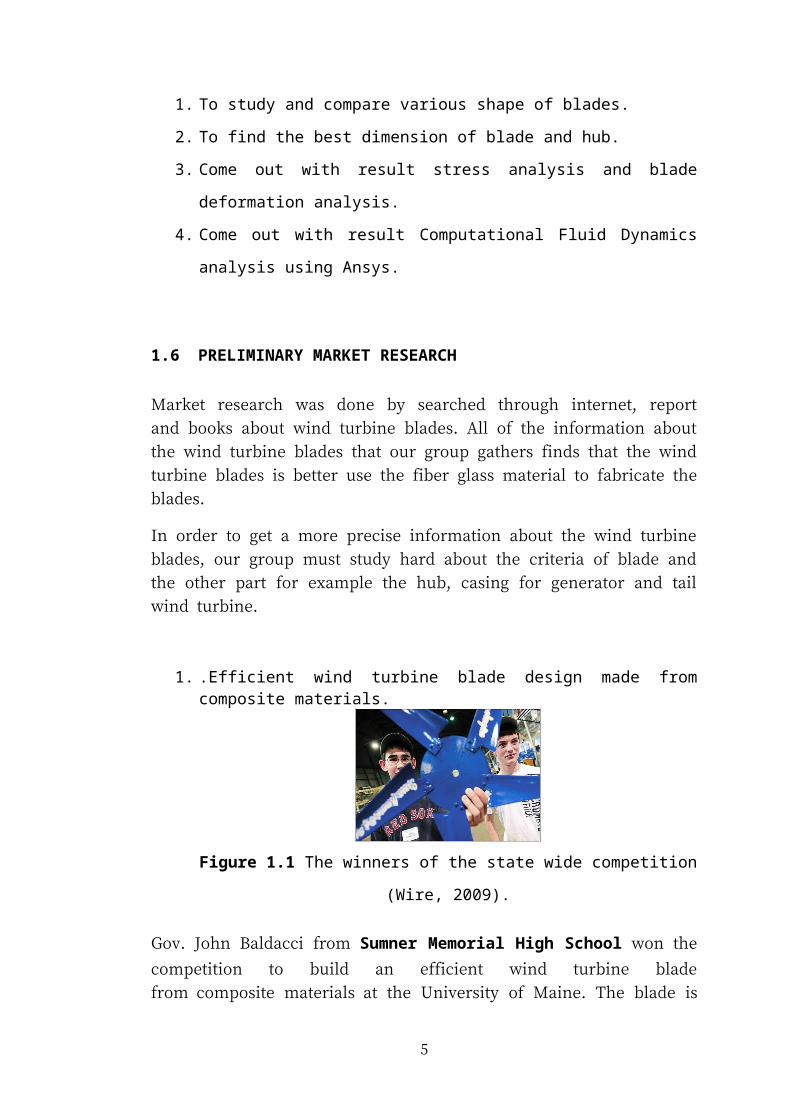
1. .Efficient wind turbine blade design made from composite materials.
Figure 1.1 The winners of the state wide competition (Wire, 2009).
Gov. John Baldacci from Sumner Memorial High School won the competition to
build an efficient wind turbine blade from composite materials at the University of
Maine. The blade is especially designed for maximum wattage keeping in mind the
overall lightness and aerodynamics. This student teams sent a composite materials to
design a prototype blade. This blade should be no longer than 18 inches and the
turbines could be no greater than 42 inches in diameter. The teams also wrapped their
blades with a fibreglass cloth and infused them with a resin that hardened the blades.
The overall aim was to design a blade that would generate the most wattage.
4
2.
Figure 1.2 Advantages of composite material (Shed, 2010).
Fibre glass has advantage for example higher strength to weight ratio as compared to
other materials. Besides that this material is light weight components are easier to
install, requiring less equipment, time, and manpower costs.
3.
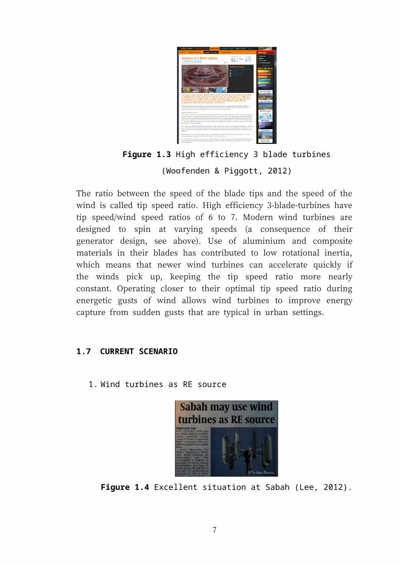
Figure 1.3 High efficiency 3 blade turbines (Woofenden & Piggott, 2012)
The ratio between the speed of the blade tips and the speed of the wind is called tip
speed ratio. High efficiency 3-blade-turbines have tip speed/wind speed ratios of 6 to
7. Modern wind turbines are designed to spin at varying speeds (a consequence of
their generator design, see above). Use of aluminium and composite materials in
their blades has contributed to low rotational inertia, which means that newer wind
turbines can accelerate quickly if the winds pick up, keeping the tip speed ratio more
nearly constant. Operating closer to their optimal tip speed ratio during energetic
gusts of wind allows wind turbines to improve energy capture from sudden gusts that
are typical in urban settings.
5
1.7 CURRENT SCENARIO
1. Wind turbines as RE source
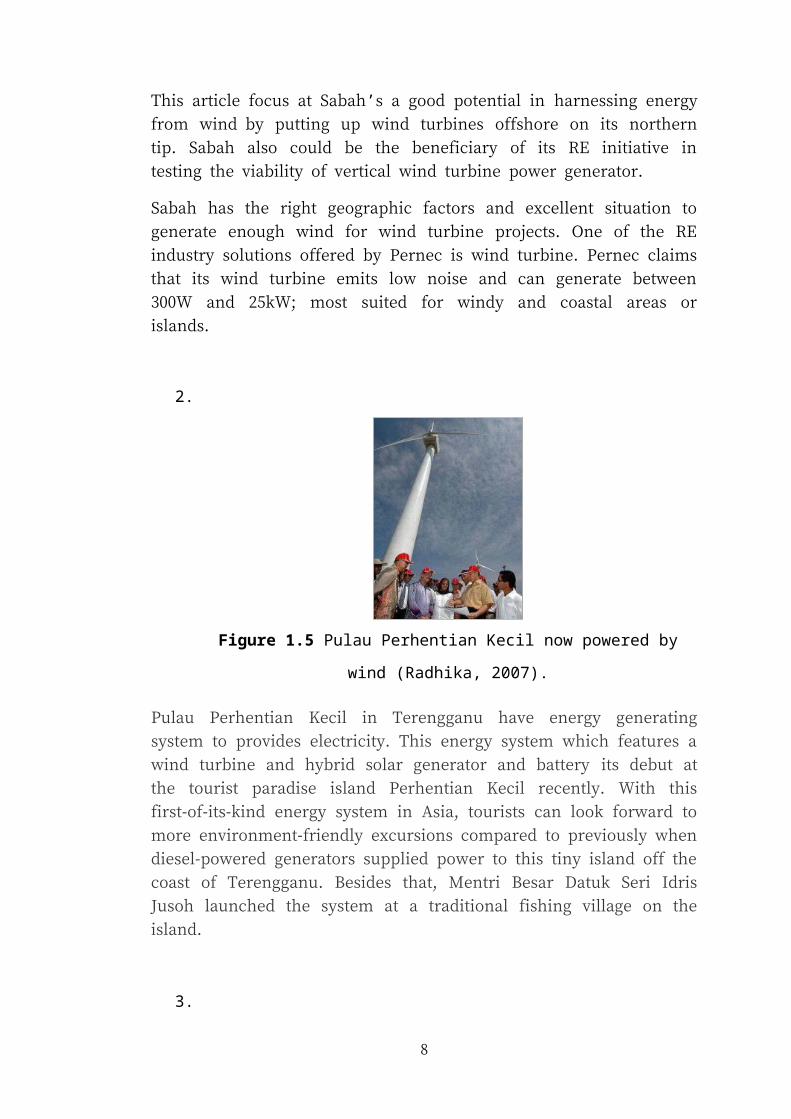
Figure 1.4 Excellent situation at Sabah (Lee, 2012).
This article focus at Sabah’s a good potential in harnessing energy from wind by
putting up wind turbines offshore on its northern tip. Sabah also could be the
beneficiary of its RE initiative in testing the viability of vertical wind turbine power
generator.
Sabah has the right geographic factors and excellent situation to generate enough
wind for wind turbine projects. One of the RE industry solutions offered by Pernec is
wind turbine. Pernec claims that its wind turbine emits low noise and can generate
between 300W and 25kW; most suited for windy and coastal areas or islands.
2.
Figure 1.5 Pulau Perhentian Kecil now powered by wind (Radhika, 2007).
Pulau Perhentian Kecil in Terengganu have energy generating system to provides
electricity. This energy system which features a wind turbine and hybrid solar
generator and battery its debut at the tourist paradise island Perhentian Kecil
6
recently. With this first-of-its-kind energy system in Asia, tourists can look forward
to more environment-friendly excursions compared to previously when diesel-
powered generators supplied power to this tiny island off the coast of Terengganu.
Besides that, Mentri Besar Datuk Seri Idris Jusoh launched the system at a traditional
fishing village on the island.
3.
Figure 1.6 Commercial wind energy generation may be possible after all
(Shaharuddin, 2012).
Dr Chong Wen Tong from Universiti Malaya say, who has always been interested in
finding a reliable wind source for energy generation, may have found the answer.
Around three years ago, he developed a wind energy recovery system from air
exhaust outlet those great fans usually located on top of commercial buildings for air
conditioning.
7
4.
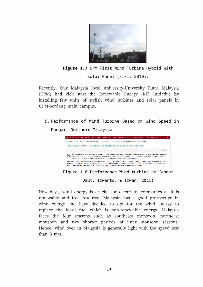
Figure 1.7 UPM First Wind Turbine Hybrid with Solar Panel (kiki,
2010).
Recently, Our Malaysia local university-University Putra Malaysia (UPM) had kick
start the Renewable Energy (RE) Initiative by installing few units of stylish wind
turbines and solar panels in UPM-Serdang main campus.
5. Performance of Wind Turbine Based on Wind Speed in Kangar, Northern
Malaysia
Figure 1.8 Performance Wind turbine at Kangar (Daut, Irwanto, & Irwan,
2011).
Nowadays, wind energy is crucial for electricity companies as it is renewable and
free resource. Malaysia has a good prospective in wind energy and have decided to
opt for the wind energy to replace the fossil fuel which is non-renewable energy.
Malaysia faces the four seasons such as southeast monsoon, northeast monsoon and
two shorter periods of inter monsoon seasons. Hence, wind over in Malaysia is
generally light with the speed less than 8 m/s.
6. Blade Material
8
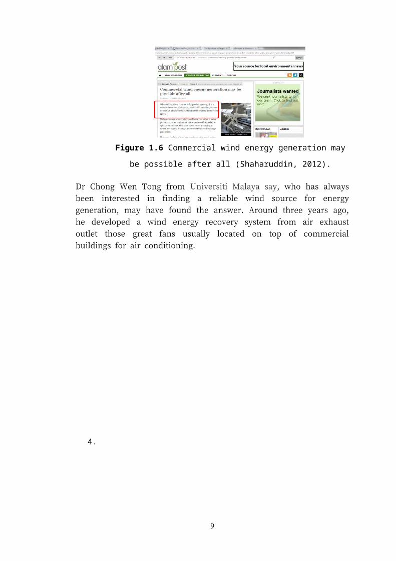
Figure 1.9 Fibre glass commonly used for Wind Turbine Blade (Austin,
2011).
Composite materials, such as fiberglass, are currently the most commonly used
materials in wind turbine construction. Fiberglass is generally only used for small,
domestic applications, because fiberglass inclines to be more fragile than other fibre
based materials. That makes fiberglass a liability for commercial purposes.
9
CHAPTER 2
LITERATURE REVIEW
2.1 WIND ENERGY
Wind energy was start development since the early 1980’s. Wind energy system has
own advantages between the other renewable energy. The rotor must have design of
aerodynamic device, for example the wing or rotor blade with an aerodynamic shape,
to be able to rotate smoothly. Today nearly all wind turbines have three blades
because the stability better than using two blades. Besides that, the high noise can
reduce if usage three blades (Brondsted, Lilholt, & Lystrup, 2005).
2.2 WIND TURBINE BLADES
2.2.1 Design of Wind Turbine Blades
Design of blades is the most important part to conduct the wind turbine system.
Thus, blades also must have special design to capture the maximum wind. Blade
design for the small horizontal axis wind turbine is not difficult because there have
various designs announce on the internet. But then, for the vertical axis wind turbine
is really a difficult to design because there have no common model blades design yet.
Blade design also starts with air foil shapes. Air foil sections also take serious for this
schem (Blanton & Preston, 2012). It is anticipated that the aero-elastic blade will
passively adapt its shape to the wind direction and speed leading to improve
aerodynamic blade characteristic, reduce loads, and improved performance Airfoil
with increased lift coefficient (Sunara, 2012). Design of blades can improve the
length to capture more wind at low speed, and then can retract to operate safely and
efficiently at high wind speeds (Richardson, 2009).
10
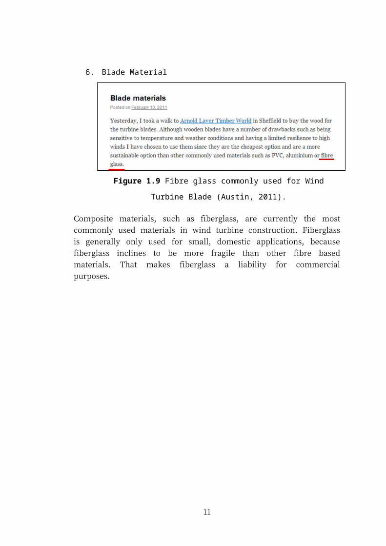
Table 2.1 The two mechanisms of propulsion compared (Schubel & Crossley, 2012).
Propulsion Drag Lift
Diagram
Relative WindVelocity
= Wind velocity - Blade velocity ¿√ 2
3Wind Velocity2+BladeVelocity (dr )
Table 2.2 Main features of the two rotor designs (ITDG, Fernando, & Piggott, 2001).
Country of
origin DesignerPeru Teodoro Sanchez Sri Lanka Sunith Fernando
Blade section NACA 4412 K2
Diameter 1.7metres 2.0metres
Tip speed ratio 5 6
Number of
blades3 2
Design
11
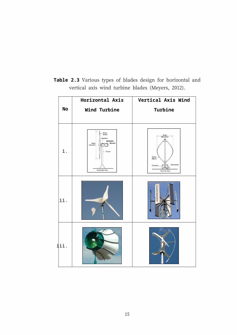
Table 2.3 Various types of blades design for horizontal and vertical axis wind
turbine blades (Meyers, 2012).
NoHorizontal Axis Wind
Turbine
Vertical Axis Wind Turbine
i.
ii.
iii.
iv.
12

v.
vi.
vii.
13
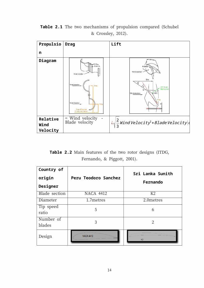
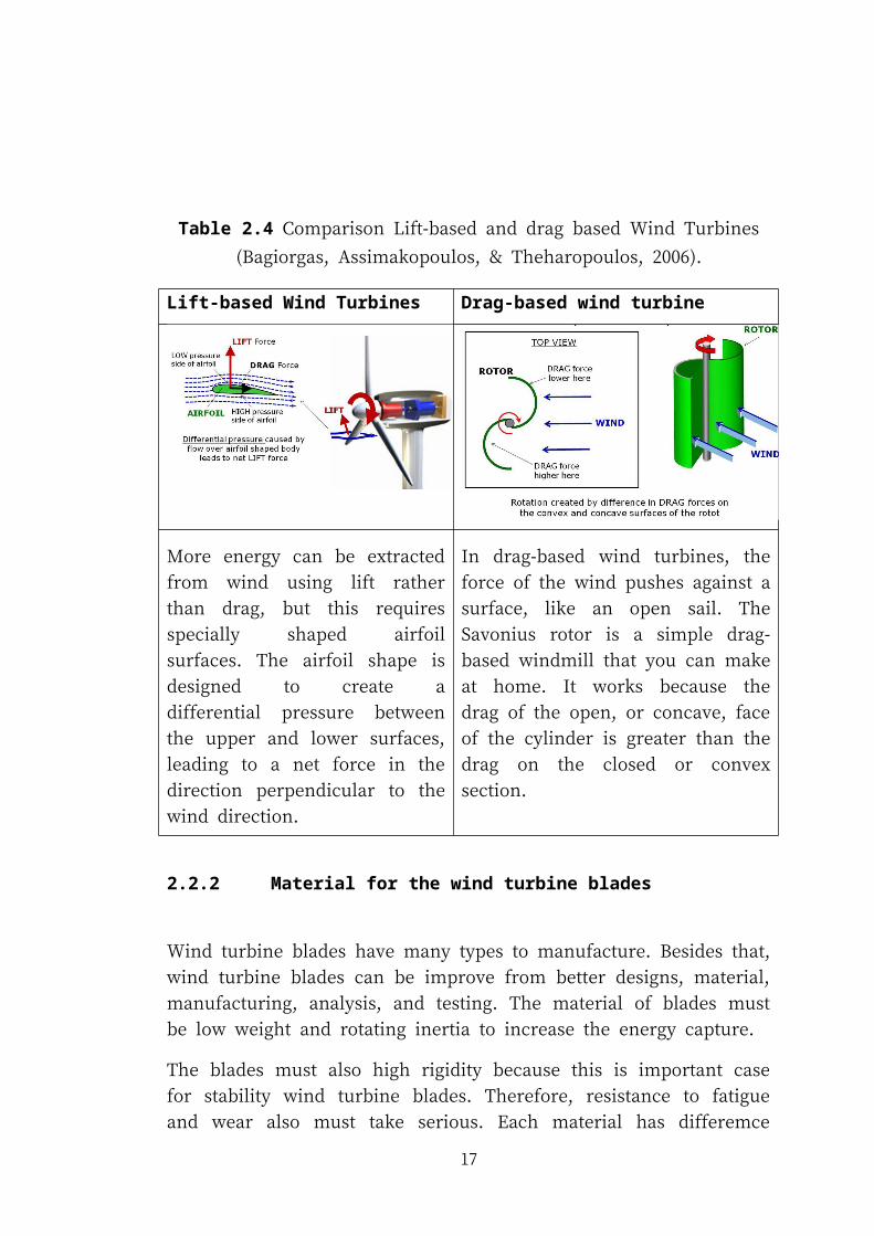
Table 2.4 Comparison Lift-based and drag based Wind Turbines (Bagiorgas,
Assimakopoulos, & Theharopoulos, 2006).
Lift-based Wind Turbines Drag-based wind turbine
More energy can be extracted from
wind using lift rather than drag, but
this requires specially shaped airfoil
surfaces. The airfoil shape is designed
to create a differential pressure
between the upper and lower surfaces,
leading to a net force in the direction
perpendicular to the wind direction.
In drag-based wind turbines, the force of
the wind pushes against a surface, like an
open sail. The Savonius rotor is a simple
drag-based windmill that you can make at
home. It works because the drag of the
open, or concave, face of the cylinder is
greater than the drag on the closed or
convex section.
2.2.2 Material for the wind turbine blades
Wind turbine blades have many types to manufacture. Besides that, wind turbine
blades can be improve from better designs, material, manufacturing, analysis, and
testing. The material of blades must be low weight and rotating inertia to increase the
energy capture.
The blades must also high rigidity because this is important case for stability wind
turbine blades. Therefore, resistance to fatigue and wear also must take serious. Each
material has differemce advantages and disadvantages in the manufacture of blades
design. Today nearly, all large horizontal-axis wind turbine blades are usually made
from composite materials to reduce the weight while attaining a reasonable strength
to weight ratio (Chena, Gaub, & Chena, 2011). Composite material has many
14
advantages for example very stiff and strong, and yet lightweight fibres of glass
(Walczyk, 2010).
a) Materials Requirements
These operational parameters and conditions lead to the following requirements
focused on stiffness, density, and long-time fatigue:
High material stiffness is needed to maintain optimal aerodynamic
performance.
Low density is needed to reduce gravity forces.
Long fatigue life is needed to reduce material degradation.
2.2.3 Difference material used for Wind Turbine Blades
The description of difference material as below:
i. Fibre glass Blades is the popular wind turbine blades material for
both large and small wind turbines. Fibre glass materials are ideal for
producing wind turbine blades because of their strength, light weight
and ability to be tailored to provide the precise mechanical properties
needed for any blade design. Fiberglass also has many positive
comments between other material from the article and in website
forum (Richardson, 2009).
Figure 2.1 Fiber glass blades (Richardson, 2009).
15
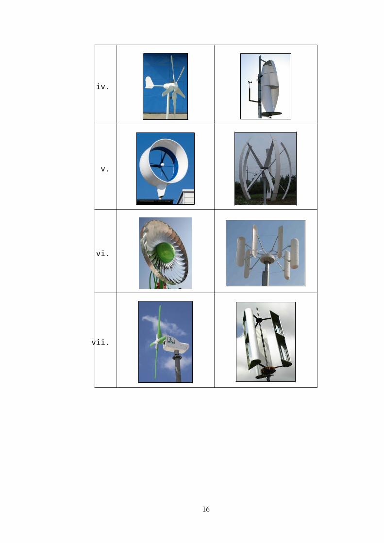
Table 2.5 Advantages and disadvantage of Fiber glass wind turbine blades (Brondsted et al., 2005).
Advantages Disadvantages
Resin/catalyst levels and the resin
content in the fiber are accurately
set by the materials manufacturer.
High fiber volumes can be safely
achieved.
Materials cost is higher.
The materials have excellent health
and safety characteristics and are
clean to work with.
Autoclaves are usually required to
cure the component. These are
expensive, slow to operate and
limited in size.
Fiber cost is minimized in
unidirectional tapes since there is no
secondary process to convert fiber
into fabric prior to use.
Tooling needs to be able to
withstand the process temperatures
and pressures involved.
Resin chemistry can be optimized for
mechanical and thermal
performance, with the high viscosity
resins being impregnable due to the
manufacturing process.
Core materials need to be able to
withstand the process temperatures
and pressure.
The extended working times means
that structurally optimized, complex
lay‐ups can be readily achieved.
Difficult to make.
Potential for automation and labor saving.
16
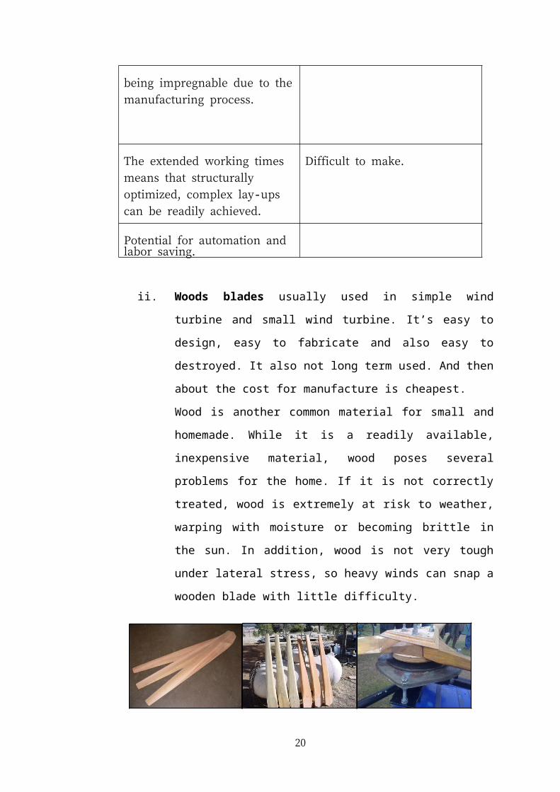
ii. Woods blades usually used in simple wind turbine and small wind
turbine. It’s easy to design, easy to fabricate and also easy to
destroyed. It also not long term used. And then about the cost for
manufacture is cheapest.
Wood is another common material for small and homemade. While it
is a readily available, inexpensive material, wood poses several
problems for the home. If it is not correctly treated, wood is extremely
at risk to weather, warping with moisture or becoming brittle in the
sun. In addition, wood is not very tough under lateral stress, so heavy
winds can snap a wooden blade with little difficulty.
Figure 2.2 Wood blades (Richardson, 2009).
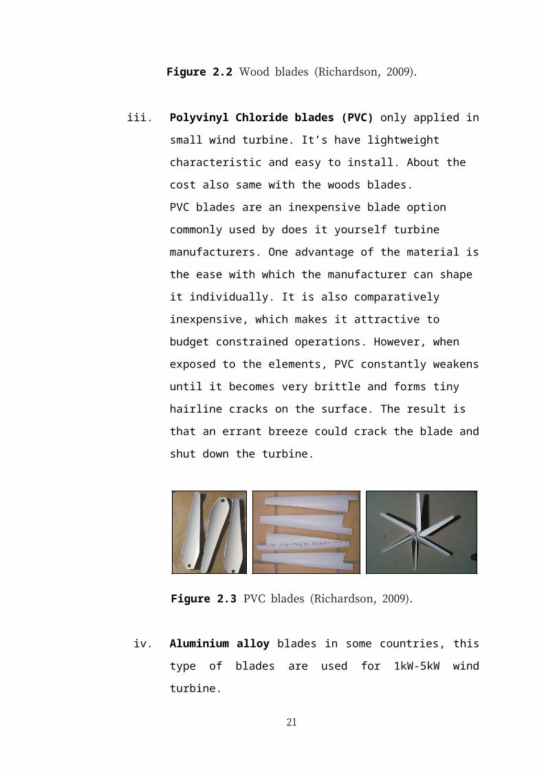
iii. Polyvinyl Chloride blades (PVC) only applied in small wind turbine.
It’s have lightweight characteristic and easy to install. About the cost
also same with the woods blades.
PVC blades are an inexpensive blade option commonly used by does
it yourself turbine manufacturers. One advantage of the material is the
ease with which the manufacturer can shape it individually. It is also
comparatively inexpensive, which makes it attractive to budget
constrained operations. However, when exposed to the elements, PVC
constantly weakens until it becomes very brittle and forms tiny
hairline cracks on the surface. The result is that an errant breeze could
crack the blade and shut down the turbine.
17
Figure 2.3 PVC blades (Richardson, 2009).
iv. Aluminium alloy blades in some countries, this type of blades are
used for 1kW-5kW wind turbine.
Many manufacturers offer precision built aluminium blades. While
most large scale generators do not use these blades, they are an
excellent material for small turbines. While they are relatively heavy
compared to plastics, aluminium blades are weather resistant, resilient
and available from many suppliers. The down side is that they are
more expensive than other options. Furthermore, the maximum rotor
diameter is strictly limited by the material's weight.
Figure 2.4 Aluminium alloy blades (Richardson, 2009).
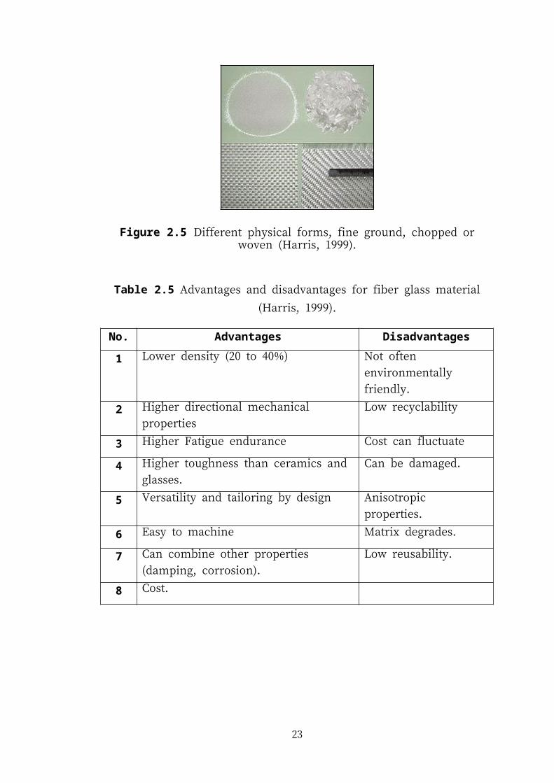
2.2.4 Fiber Glass Material
Fiberglass is a lightweight, extremely strong, and robust material. Even if strength
properties are somewhat lower than carbon fiber and it is less stiff, the material is
typically far less brittle, and the raw materials are much less expensive. Its greater
part strength and weight properties are also very favorable when compared to metals,
and it can be easily formed using molding processes. Glass fibers for composites
have a good combination to manufacture the small wind turbine blades (Brondsted et
al., 2005).
18
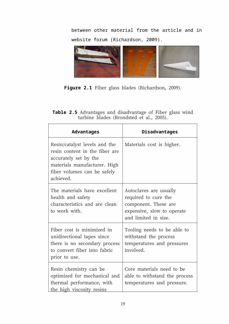
Figure 2.5 Different physical forms, fine ground, chopped or woven (Harris, 1999).
Table 2.5 Advantages and disadvantages for fiber glass material (Harris, 1999).
No. Advantages Disadvantages
1 Lower density (20 to 40%) Not often environmentally
friendly.
2 Higher directional mechanical properties Low recyclability
3 Higher Fatigue endurance Cost can fluctuate
4 Higher toughness than ceramics and glasses. Can be damaged.
5 Versatility and tailoring by design Anisotropic properties.
6 Easy to machine Matrix degrades.
7 Can combine other properties (damping,
corrosion).
Low reusability.
8 Cost.
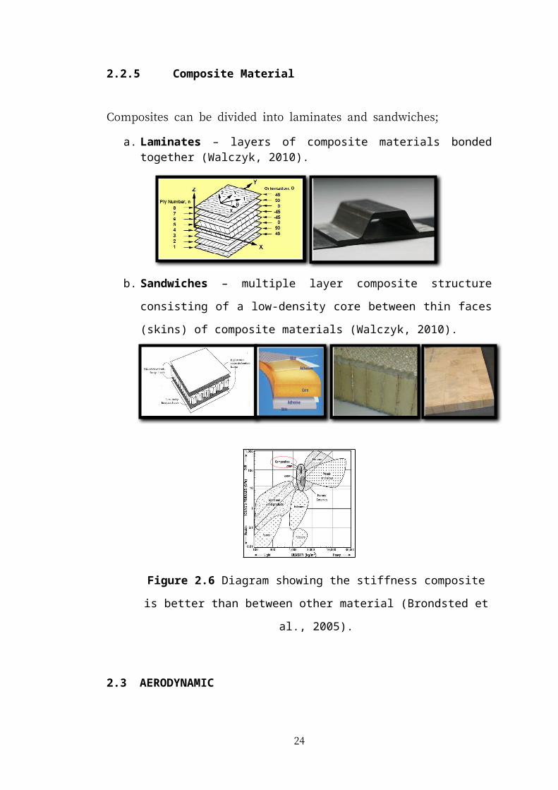
2.2.5 Composite Material
Composites can be divided into laminates and sandwiches;
19
a. Laminates – layers of composite materials bonded together (Walczyk, 2010).
b. Sandwiches – multiple layer composite structure consisting of a low‐density
core between thin faces (skins) of composite materials (Walczyk, 2010).
Figure 2.6 Diagram showing the stiffness composite is better than between
other material (Brondsted et al., 2005).
2.3 AERODYNAMIC
Aerodynamic performance is major for efficient rotor design. If don’t have
aerodynamic the blades high possibility can’t operate. Aerodynamics is a very
important aspect of wind turbines. There are still some fundamental concepts that
apply to all turbines. The aerodynamics of a horizontal axis wind turbine (HAWT) is
not straight forward. The air flow at the blades is not the same as the airflow further
away from the turbine. A resistant drag force which clash with the motion of the
blade is also generated by friction which must be reduced (Ph. Devinant, 2002).
20
2.3.1 Number of Blades
For large marketable machines, the upwind, three bladed rotor is the industry
accepted the configurations. The three bladed also have advantages over by using the
two bladed configurations. For the blade number choice is then a balance among
blade stiffness for tower clearance, aerodynamic efficiency, and tower shadow
impulsive noise (Sunara, 2012). The three bladed rotor configurations appear to
provide the best balance.
Another consideration the three blades is a more dynamically balanced rotor. In
calculation, two-bladed rotors are more sensitive to one per rev, rotor mass also
imbalance vibration. For more rotor dynamics of a three bladed rotor tend to result in
lower operating and maintenance cost (Tangler, 2000).
The main reason why the two blade rotor can work at higher tip speed ratio is that it
only has two blades. The smaller, three bladed rotors will have a slower tip speed,
but will run more smoothly because it has three blades. If use larger than 2.0 metre
diameter rotor the blades will sweep across more wind, and can increase the power,
in a given wind speed (ITDG et al., 2001).
2.3.2 Structural for Blades
As the Wind Energy Market has matured the optimization of blade design has
become critical as blade lengths and weights have increased. As a consequence the
one core fits all approach is no longer relevant for a modern wind turbine blade.
Structural core is used in both the structural shell and shear webs of a standard
infusion blade design. The material requirements for a structural core can vary
considerably from shell to shear web and also from one area of a shell to another.
Therefore, to optimize the design, weight and performance of a blade the blade
designer may make use of a number of core products.
21
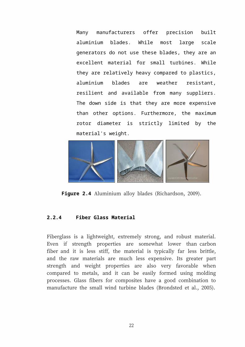
Figure 2.7 Structural of blades(Walczyk, 2010).
a) Structural and Materials information (Valencia, 2004):
Materials used in the construction of the blade.
Engineering properties of the materials: Young’s modulus,
Poisson’s ratio, failure strains.
Materials lay-up and orientation of the layers.
Materials used in the construction of shear webs and dimensions and positions relative to the air foil geometries.
2.3.3 Structural Blade Regions
The modern blade can be divided into three main areas classified by aerodynamic
and structural function
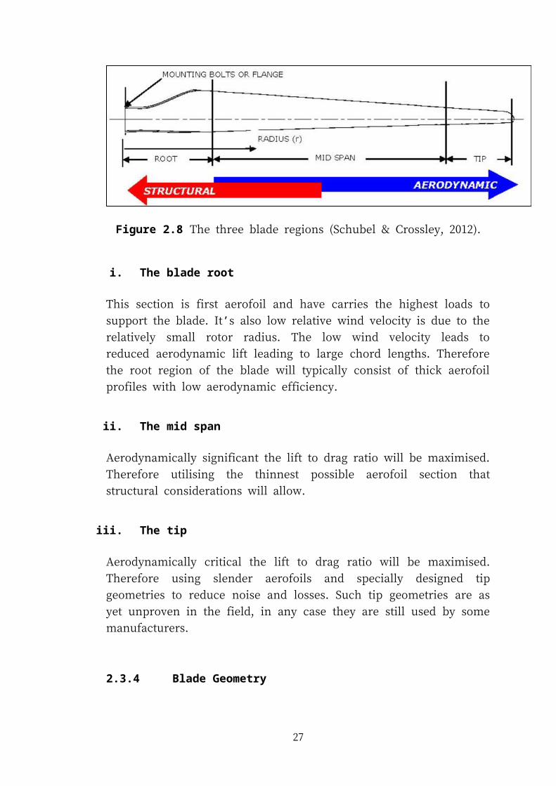
Figure 2.8 The three blade regions (Schubel & Crossley, 2012).
i. The blade root
22
This section is first aerofoil and have carries the highest loads to support the blade.
It’s also low relative wind velocity is due to the relatively small rotor radius. The low
wind velocity leads to reduced aerodynamic lift leading to large chord lengths.
Therefore the root region of the blade will typically consist of thick aerofoil profiles
with low aerodynamic efficiency.
ii. The mid span
Aerodynamically significant the lift to drag ratio will be maximised. Therefore
utilising the thinnest possible aerofoil section that structural considerations will
allow.
iii. The tip
Aerodynamically critical the lift to drag ratio will be maximised. Therefore using
slender aerofoils and specially designed tip geometries to reduce noise and losses.
Such tip geometries are as yet unproven in the field, in any case they are still used by
some manufacturers.
2.3.4 Blade Geometry
Blade Geometry Minimum cost of energy is the criterion now used to optimize blade
geometry rather than maximum annual energy production. To optimize on minimum
cost of energy requires a multi-disciplinary method that includes an aerodynamic
model, a structural model for the blades, along with cost models for the blades and
all the major wind turbine components. Minimum cost of energy also benefits from
higher rotor speeds, which are constrained by noise considerations (ITDG et al.,
2001).
Geometric information (Valencia, 2004):
23
Aerofoil geometry at known stations from the root.
Length of the blade.
Twist angle of the blade at several aerofoil stations.
Chord length.
The distance from the nose of a station to the blade generator line. (X-offset).
Shear web dimensions and positions relative to the aerofoil geometries
previously defined.
2.3.5 Blade Element
In blades element have two key assumptions (Ingram, 2011):
There are no aerodynamic interactions between different blade elements
The forces on the blade elements are solely determined by the lift and drag
coefficients
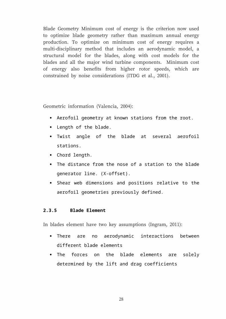
Figure 2.9 Rotating Annular Stream tube notation (Ingram, 2011).
Figure 2.10 The Blade Element Model (Ingram, 2011).
The forces on the blade element are shown in Figure 4, note that by definition the lift
and drag forces are perpendicular and parallel to the incoming flow (Ingram, 2011).
24
Figure 2.11 Forces on the turbine blade (Ingram, 2011).
2.3.6 Angle of attack
To become the best performance in wind turbine system angle of attack also can
apply. The blade is deformed due to wind, when a blade is rotate. This deformation
makes the angle of attack at the tip portion of the wind turbine blade larger than a
design value, thus increasing noise (Hayashi, Hosoya, & Karikomi, 2010).
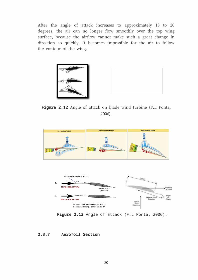
After the angle of attack increases to approximately 18 to 20 degrees, the air can no
longer flow smoothly over the top wing surface, because the airflow cannot make
such a great change in direction so quickly, it becomes impossible for the air to
follow the contour of the wing.
Figure 2.12 Angle of attack on blade wind turbine (F.L Ponta, 2006).
25
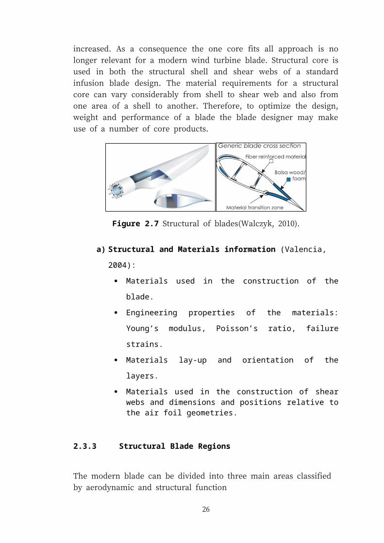
Figure 2.13 Angle of attack (F.L Ponta, 2006).
2.3.7 Aerofoil Section
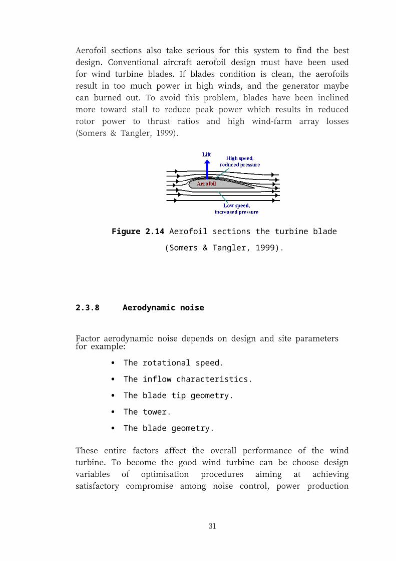
Aerofoil sections also take serious for this system to find the best design.
Conventional aircraft aerofoil design must have been used for wind turbine blades. If
blades condition is clean, the aerofoils result in too much power in high winds, and
the generator maybe can burned out. To avoid this problem, blades have been
inclined more toward stall to reduce peak power which results in reduced rotor power
to thrust ratios and high wind-farm array losses (Somers & Tangler, 1999).
Figure 2.14 Aerofoil sections the turbine blade (Somers & Tangler, 1999).
2.3.8 Aerodynamic noise
26
Factor aerodynamic noise depends on design and site parameters for example:
The rotational speed.
The inflow characteristics.
The blade tip geometry.
The tower.
The blade geometry.
These entire factors affect the overall performance of the wind turbine. To become
the good wind turbine can be choose design variables of optimisation procedures
aiming at achieving satisfactory compromise among noise control, power production
and costs, so as to make wind energy quieter and cheaper (Hansen, 2008).
2.4 BLADE PLAN SHAPE AND QUANTITY
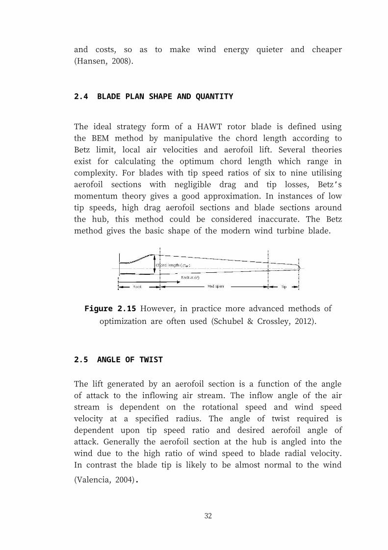
The ideal strategy form of a HAWT rotor blade is defined using the BEM method by
manipulative the chord length according to Betz limit, local air velocities and
aerofoil lift. Several theories exist for calculating the optimum chord length which
range in complexity. For blades with tip speed ratios of six to nine utilising aerofoil
sections with negligible drag and tip losses, Betz’s momentum theory gives a good
approximation. In instances of low tip speeds, high drag aerofoil sections and blade
sections around the hub, this method could be considered inaccurate. The Betz
method gives the basic shape of the modern wind turbine blade.
Figure 2.15 However, in practice more advanced methods of optimization are often
used (Schubel & Crossley, 2012).
2.5 ANGLE OF TWIST
27
The lift generated by an aerofoil section is a function of the angle of attack to the
inflowing air stream. The inflow angle of the air stream is dependent on the
rotational speed and wind speed velocity at a specified radius. The angle of twist
required is dependent upon tip speed ratio and desired aerofoil angle of attack.
Generally the aerofoil section at the hub is angled into the wind due to the high ratio
of wind speed to blade radial velocity. In contrast the blade tip is likely to be almost
normal to the wind (Valencia, 2004).
The total angle of twist in a blade maybe reduced simplifying the blade shape to cut
manufacturing costs. However, this may force aerofoils to operate at less than
optimum angles of attack where lift to drag ratio is reduced. Such simplifications
must be well justified considering the overall loss in turbine performance.
2.6 WINGS AND LIFT
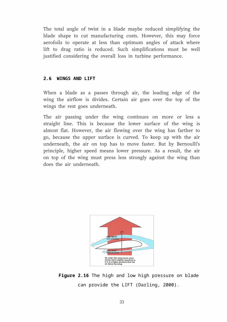
When a blade as a passes through air, the leading edge of the wing the airflow is
divides. Certain air goes over the top of the wings the rest goes underneath.
The air passing under the wing continues on more or less a straight line. This is
because the lower surface of the wing is almost flat. However, the air flowing over
the wing has farther to go, because the upper surface is curved. To keep up with the
air underneath, the air on top has to move faster. But by Bernoulli's principle, higher
speed means lower pressure. As a result, the air on top of the wing must press less
strongly against the wing than does the air underneath.
28
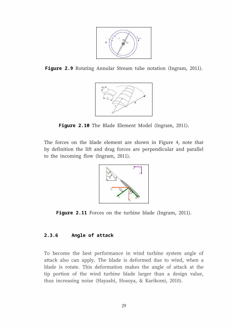
Figure 2.16 The high and low high pressure on blade can provide the LIFT
(Darling, 2000).
Since the downward pressure on the top of the moving wing is less than the upward
pressure on the bottom of the wing, there is an overall upward force. This upward
force is called LIFT.
2.7 WIND SPEED
The wind speed data was taken and been analyze at the certain place in Malaysia
such as at Kudat, Labuan (Sabah) and Petaling Jaya (Selangor). The data was taken
from 2006 to 2008 and the crucial outcomes from this analysis are (M.R. Islama,
2011).
The monthly and yearly highest mean wind speeds were 4.76 m/s at
Kudat and 3.39 m/s at Labuan respectively.
The maximum wind power density was found to be 67.40 W/m2 at
Kudat for the year 2008.
The maximum wind energy density was found to be 590.40 kWh/m2/
year at Kudat in 2008.
The highest most probable wind speed and wind speed carrying
maximum energy were estimated 2.44 m/s at Labuan in 2007 and 6.02
m/s at Kudat in 2007.
The maximum deviation, at wind speed more than 2 m/s
29
Small scale wind energy can be generated at the turbine height of 100 m. At very low
wind speeds the turbine produces too little torque to overcome friction. Once the
wind speed is sufficient to allow the turbine to rotate, the output power is
approximately proportional to the cube of the wind speed. This remains true up to the
rated speed. Above this speed the power production levels off, and with stall
regulated turbines actually drops as wind speeds are increased. Finally at an even
higher wind speed, the furling speed, the turbine is shut down to avoid damage to the
machine (Othman, 2010).
During this time, the total wind speed can reach until 12m/s. The electricity
generation needs at least 4 to 4.5 m/s or 9 to 10.2 mph of total wind speed. Generally,
Malaysia wind is relatively calm for almost 30% to 50% of the year (Yusoff, 2006).
At this time the highest mean daily wind speed 3.8 m/s recorded Mersing, Johor. For
highest maximum wind speed 41.7 m/s is recorded at Kuching, Sarawak on 15
September 1992. This data collected from Ministry of Science, Technology and
Innovation (MOSTI).
Figure 2.17 Peninsula of Malaysia
2.8 ALUMINIUM BLADE
Aluminium is a silvery white metal with a density about a third that of steel.
Aluminum was only implemented in testing situations because it was found to have a
lower fatigue level than steel. Aluminium is ductile and good heat conductor.
Aluminium is a low price metal but it has good reliability and has a low tensile
strength. Aluminum is lightweight, but weaker and less stiff than steel.
30
Properties of Aluminium has a unique and unbeatable combination of properties that
make it into a versatile, highly usable and attractive construction material.
Aluminium is light with a density one third that of steel, 2.700 kg/m3. This material
also strong with a tensile strength of 70 to 700 MPa depending on the alloy and
manufacturing process. Extrusions of the right alloy and design are as strong as
structural steel. The Young’s modulus for aluminium is a third that of steel (E =
70,000 MPa). This means that the moment of inertia has to be three times as great for
an aluminium extrusion to achieve the same deflection as a steel profile.
Aluminium blades have many advantages over other blade materials:
Improved strength and rigidity.
Better sheer strength at mounting points.
Not UV affected, long life compared to PVC or wood.
Easier and cheaper to paint, could be used unpainted with leading edge
tape.
More uniform aerofoil.
End caps are held with 4 small screws.
By using small rod in the C channel in the ends allows easy balancing.
Slightly lighter than PVC.
100% aluminium, recyclable.
31
CHAPTER 3
METHODOLOGY
3.1 INTRODUCTION
For this chapter to explain about methodology and the development of process.
Before starts this project, student should know and identify the method of project
methodology. This chapter must include in report because to identify step by step on
how the flow or progress of the project will be too successful. A lot of journal,
books, report, newspaper, website and the other to determine about wind turbine that
currently use in worldwide we can refer. If use the wind turbine we should know
about the wind, because the wind must has high wind speed velocity, but in Malaysia
is country that have low wind speed velocity. Therefore, the student has a create
ideas and brainstorming to design and find the best material blades wind turbine due
to uncertainty wind speed in Malaysia.
3.2 DESIGN PROCESS
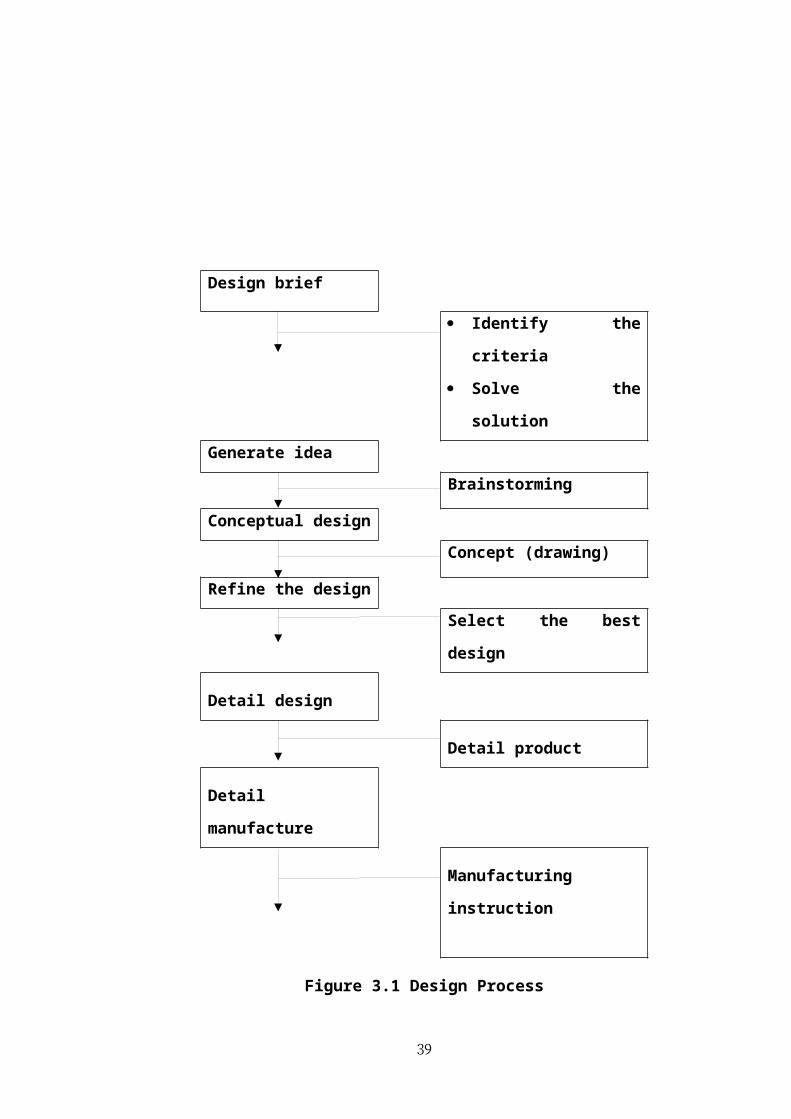
In design process to show the steps that need to follow from start until end steps.
Starting the design brief about wind turbine blades, it show a little defect or lack and
need to be improving in order to give successful product. More idea and
brainstorming required to get the solution for the problem. This process also can be
identifying the problem design. To know what material and design for suitable, an
analyzed must was done. Modification or refinement can be made to the concept
while certain steps are common in the development of most product design..
32
Design brief
Identify the criteria
Solve the solution
Generate idea
Brainstorming
Conceptual design
Concept (drawing)
Refine the design
Select the best design
Detail design
Detail product
Detail manufacture
Manufacturing instruction
Figure 3.1 Design Process
33
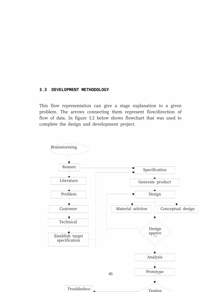
3.3 DEVELOPMENT METHODOLOGY
This flow representation can give a stage explanation to a given problem. The arrows
connecting them represent flow/direction of flow of data. In figure 3.2 below shows
flowchart that was used to complete the design and development project.
Figure 3.2 Mechanism and analysis proces flow chart
34
Brainstorming
Research
Literature review
Problem statement
Customer requirement
Technical requirement
Generate product concept
Design
Conceptual designMaterial selction
Design approva
l
Analysis
Prototype
Testing
Final product
Troubleshoot/
Rework
Specification
YES
NO
Establish target specification
3.4 GANTT CHART
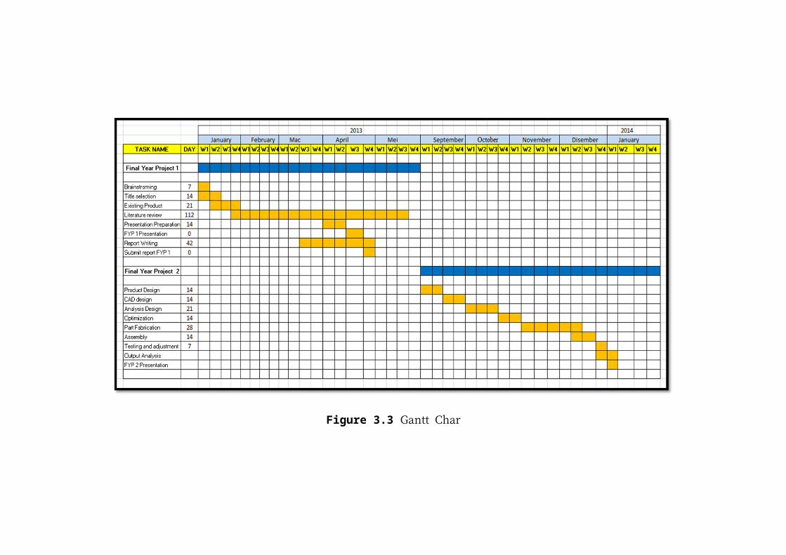
This Gantt chart is basically plan to control and helps student to follow the
prescribed task without wasting time unnecessarily. It also management for each task
and make a fabrication process going smoothly. In the other words, project schedule
can make a task going systematically and also can avoid mistake throughout the
process.
35

Figure 3.3 Gantt Char
37

3.5 CUSTOMER REQUIREMENT
Before the concept to be developed, the list of customer needs is made with group
discussion and also interviews to get customer need about the product to be
developed. The needs of the identify customer is for largely independent of any
particular product and not specification to the concepts of the choose product. Other
terms is including customer attributes and customer requirement. Its helps and guide
a designer to create a product using criteria needed.
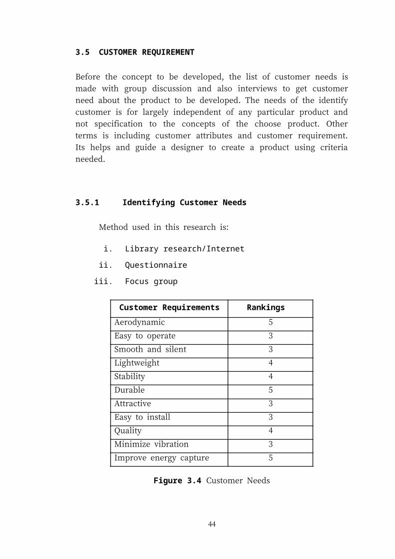
3.5.1 Identifying Customer Needs
Method used in this research is:
i. Library research/Internet
ii. Questionnaire
iii. Focus group
Customer Requirements RankingsGS
Aerodynamic 5
Easy to operate 3
Smooth and silent 3
Lightweight 4
Stability 4
Durable 5
Attractive 3
Easy to install 3
Quality 4
Minimize vibration 3
Improve energy capture 5
Figure 3.4 Customer Needs
38
Rankings:
1. Feature is undesirable, a product/ process with this feature should not be
considered.
2. Feature is not important, but would be ok to have.
3. Feature would be nice to have, but is not necessary.
4. Feature is highly desirable, a product/ process without it should be
considered.
5. Feature is critical, a product/ process without this feature should not be
considered.
3.5.2 Research Methodology for Establish Specification
Method used in this research is:
i. Quality Function Deployment (QFD)
ii. Product Design Specification (PDS)
a) Quality Function Deployment (QFD)
Quality Function Deployment (QFD) is a customer driven planning process
to guide the design, manufacturing, and marketing of goods. Through QFD,
every design, manufacturing, and control decision is made to meet the
expressed needs of customers. It uses a type of matrix diagram to present data
and information. Under QFD, all operations of a company are driven by the
voices of the customer, rather than by edicts of top management or the
opinions or desires of design engineers.
39
Strong (9) Medium (4) Weak (1)
Figure 3.5 Quality Function Deployment (QFD)
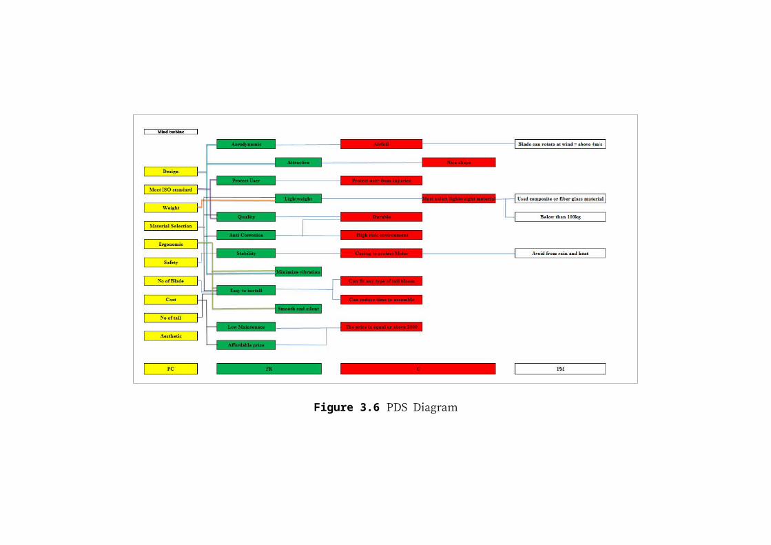
b) Product Design Specification (PDS Diagram)
A product design specification (PDS Diagram) is a statement of what a not
yet designed product is intended to do. Its aim is to ensure that the subsequent
design and development of a product meets the needs of the user. The PDS
Diagram acts as an initial boundary in the development of products.
40
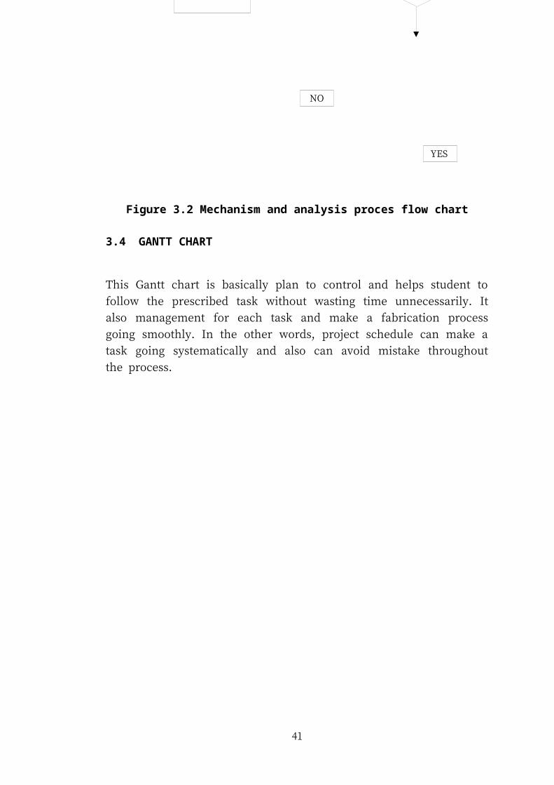
Figure 3.6 PDS Diagram
c) Sketching Product Concept
For these steps, a sketch is a rapidly executed freehand drawing that is not intended
as a finished work. Figure below shows the sketching done by the student for blade
and hub design of wind turbine.
Concept 1 Concept 2
Concept 3 Concept 4
Concept 5
Figure 3.7 Concepts of Blades Design
42

Concept 1 Concept 2
Concept 3 Concept 4
Concept 5
Figure 3.8 Concepts of Hub Design
3.6 CONCEPT SELECTION
43
3.6.1 Introduction
Concept selection is the process of evaluating concepts with respect to customer
needs and other criteria, comparing the relative strengths and weakness of the
concepts, and selecting one or more concepts for further investigation, testing, or
development.
Concept selection is an iterative process closely related to concept generation and
testing. The concept screening and scoring methods help the team refine and improve
the concepts, leading to one or more promising concepts upon which further testing
and development activities will be focused. In concepts selection involves two-stage
methodology is a:
i. Concepts screening
ii. Concept scoring
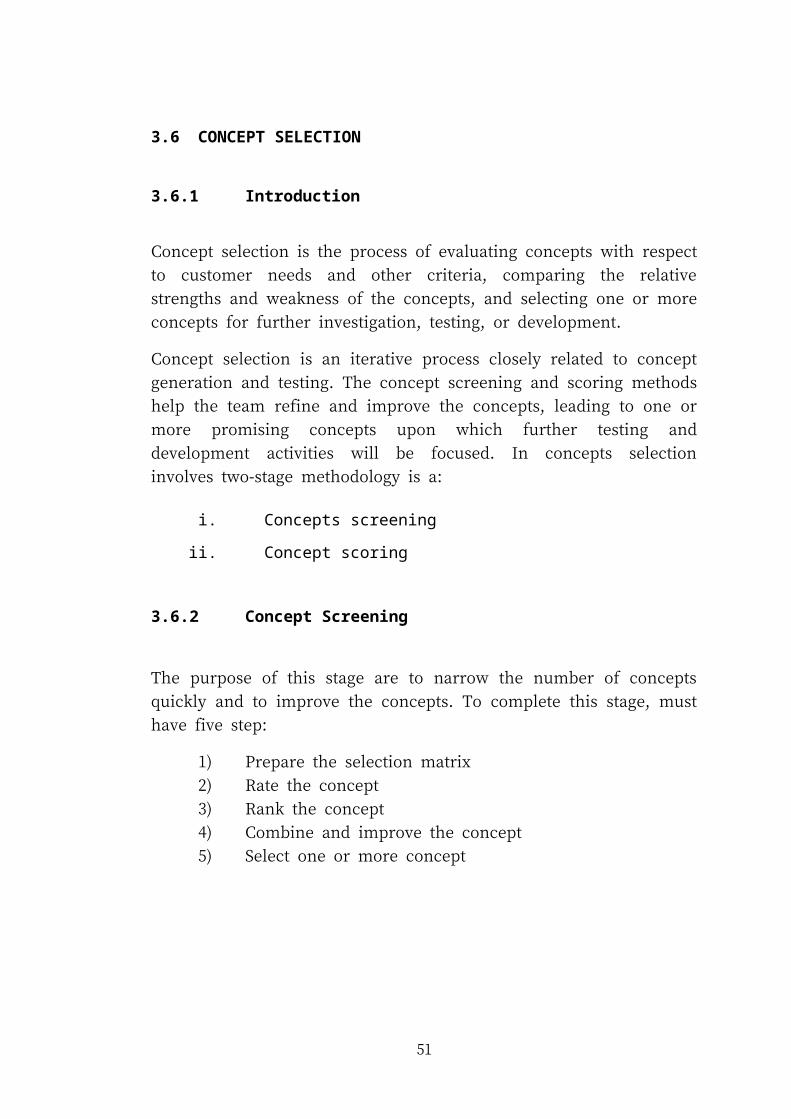
3.6.2 Concept Screening
The purpose of this stage are to narrow the number of concepts quickly and to
improve the concepts. To complete this stage, must have five step:
1) Prepare the selection matrix
2) Rate the concept
3) Rank the concept
4) Combine and improve the concept
5) Select one or more concept
44
Figure 3.9 Concept Screening
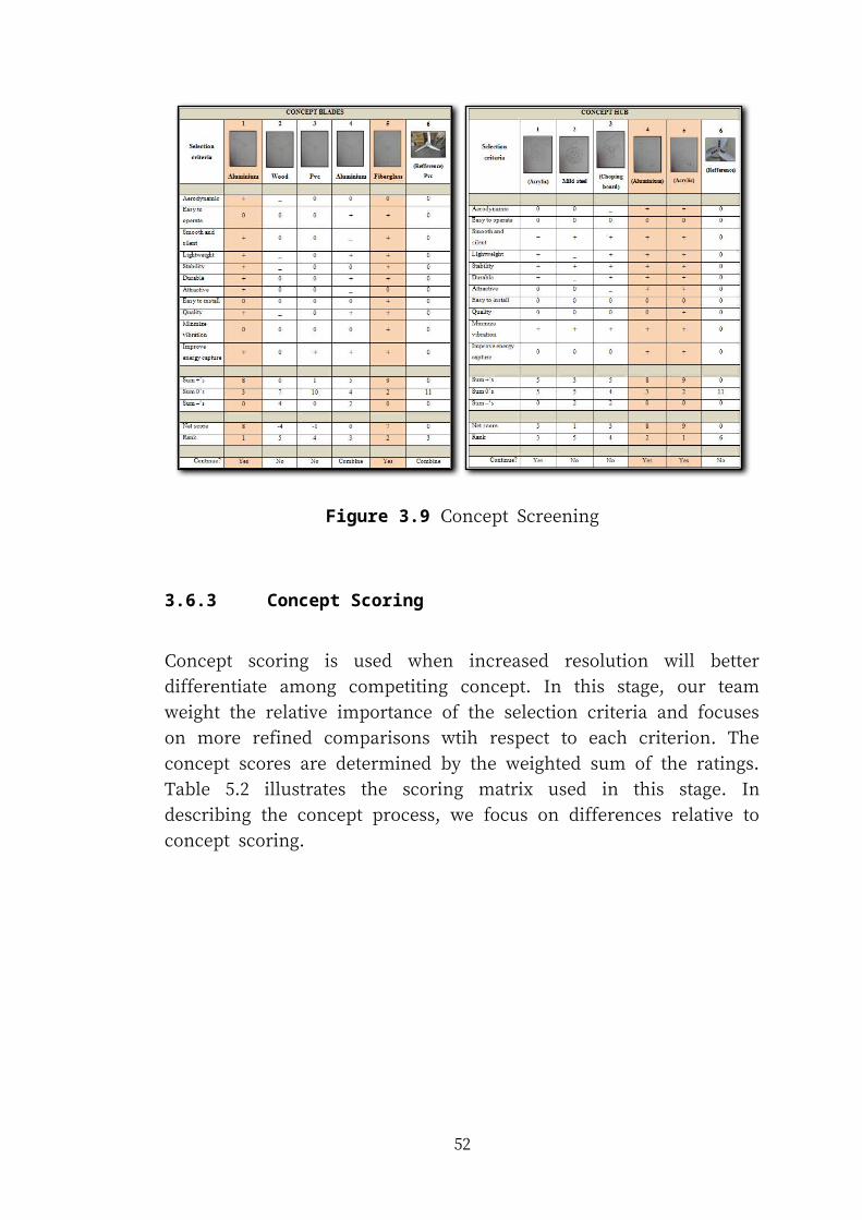
3.6.3 Concept Scoring
Concept scoring is used when increased resolution will better differentiate among
competiting concept. In this stage, our team weight the relative importance of the
selection criteria and focuses on more refined comparisons wtih respect to each
criterion. The concept scores are determined by the weighted sum of the ratings.
Table 5.2 illustrates the scoring matrix used in this stage. In describing the concept
process, we focus on differences relative to concept scoring.
45
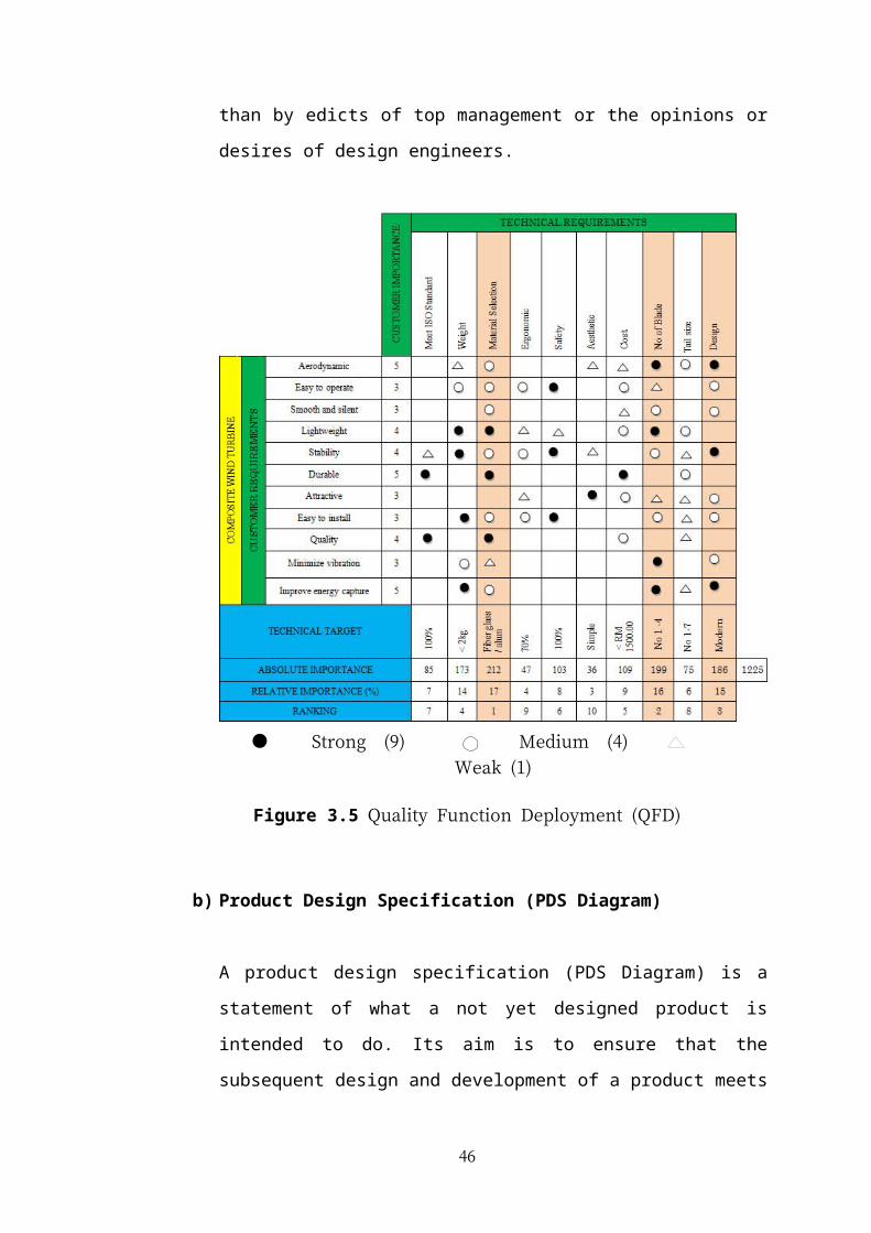
Figure 3.10 Concept Scoring
3.7 RESULT ANALYSIS FOR BLADE
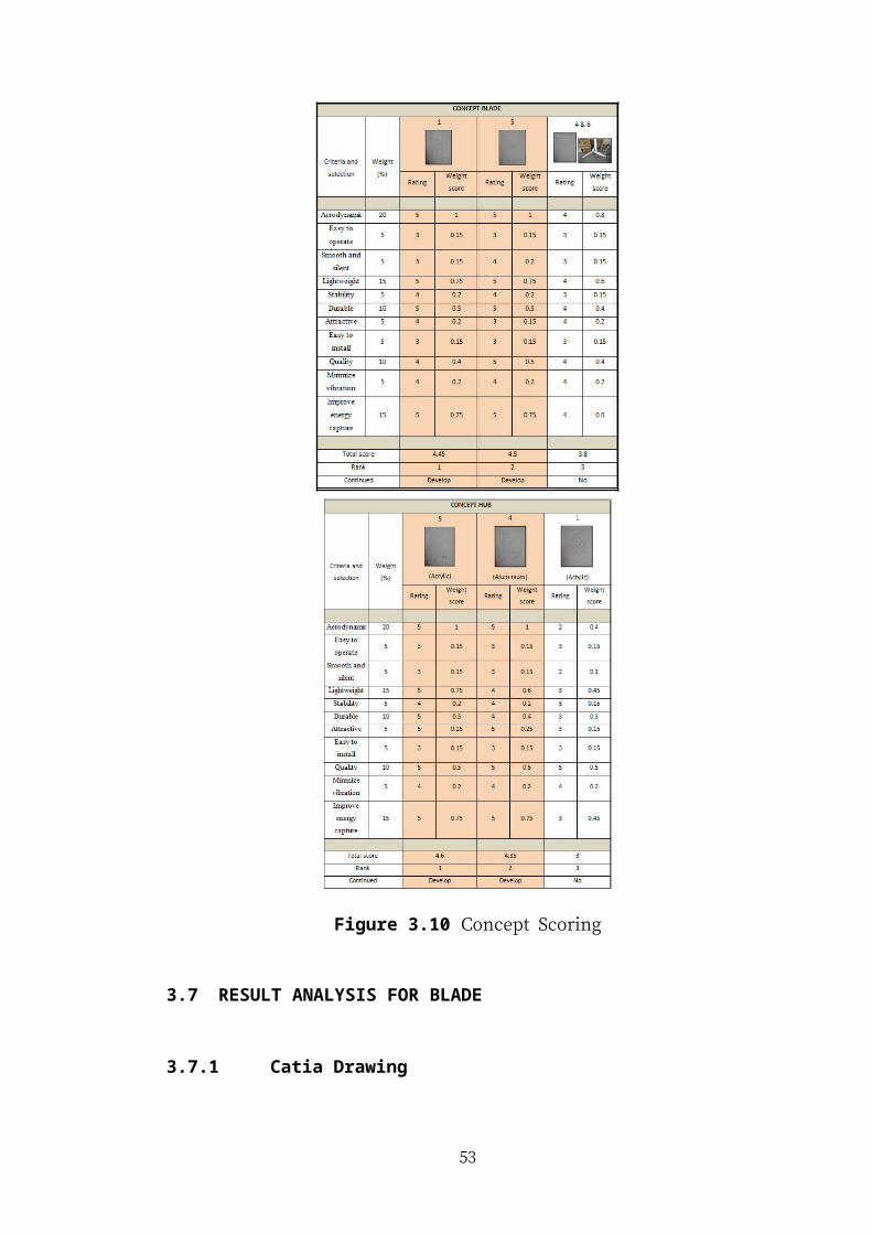
3.7.1 Catia Drawing
In this process, catia is the method for doing a detail drawing. Each parts in blade
design for small scale wind turbine was drawn and final secifications was
determined. The model of wind turbine blades of different thickness by using
mechanical packages (CATIA). Blade design are devided into two parts which are:
i. Blade
ii. Hub
Figure 3.11 Concept 5 drawing (Blade)
46

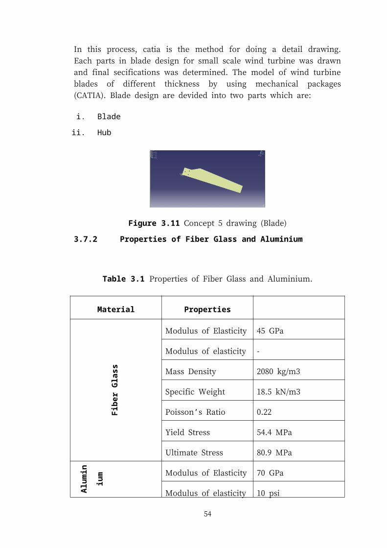
3.7.2 Properties of Fiber Glass and Aluminium
Table 3.1 Properties of Fiber Glass and Aluminium.
Material PropertiesF
iber
Gla
ss
Modulus of Elasticity 45 GPa
Modulus of elasticity -
Mass Density 2080 kg/m3
Specific Weight 18.5 kN/m3
Poisson’s Ratio 0.22
Yield Stress 54.4 MPa
Ultimate Stress 80.9 MPa
Alu
min
ium
Modulus of Elasticity 70 GPa
Modulus of elasticity 10 psi
Mass Density 2710 kg/m3
Specific Weight 26.6 kN/m3
Poisson’s Ratio 0.35
Yield Stress 20 MPa
Ultimate Stress 70 MPa
47
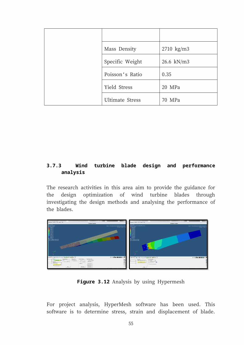
3.7.3 Wind turbine blade design and performance analysis
The research activities in this area aim to provide the guidance for the design
optimization of wind turbine blades through investigating the design methods and
analysing the performance of the blades.
Figure 3.12 Analysis by using Hypermesh
For project analysis, HyperMesh software has been used. This software is to
determine stress, strain and displacement of blade. Have two type materials for
blades and two forces different to analyzed.
Most modern wind turbine blades are made from glass-fibre reinforced polymer
(GRP) composites due to their light weight and good mechanical properties. Once
the geometric shape of the wind turbine blade is determined, the mechanical
performance of the blade is mainly determined by the lay-up scheme, which includes
the thickness distribution and fibre direction of the composites. Through stress-strain
analysis of different lay-up structures using HyperMesh software.
48
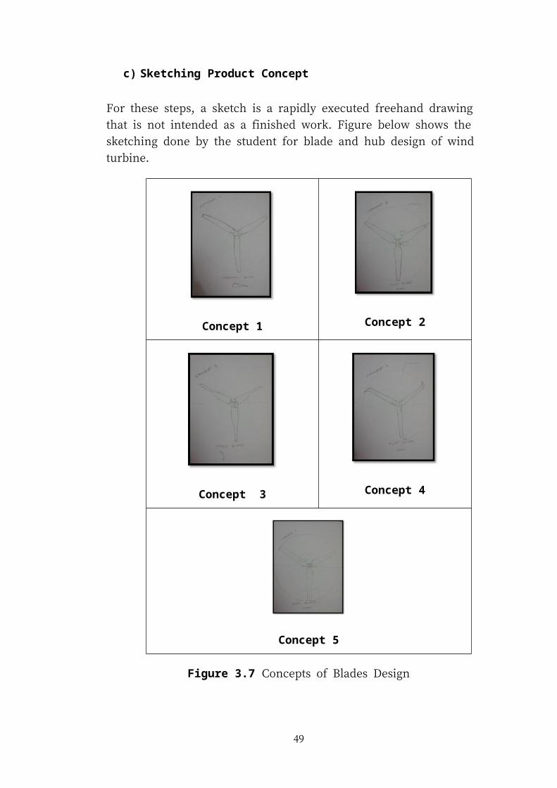
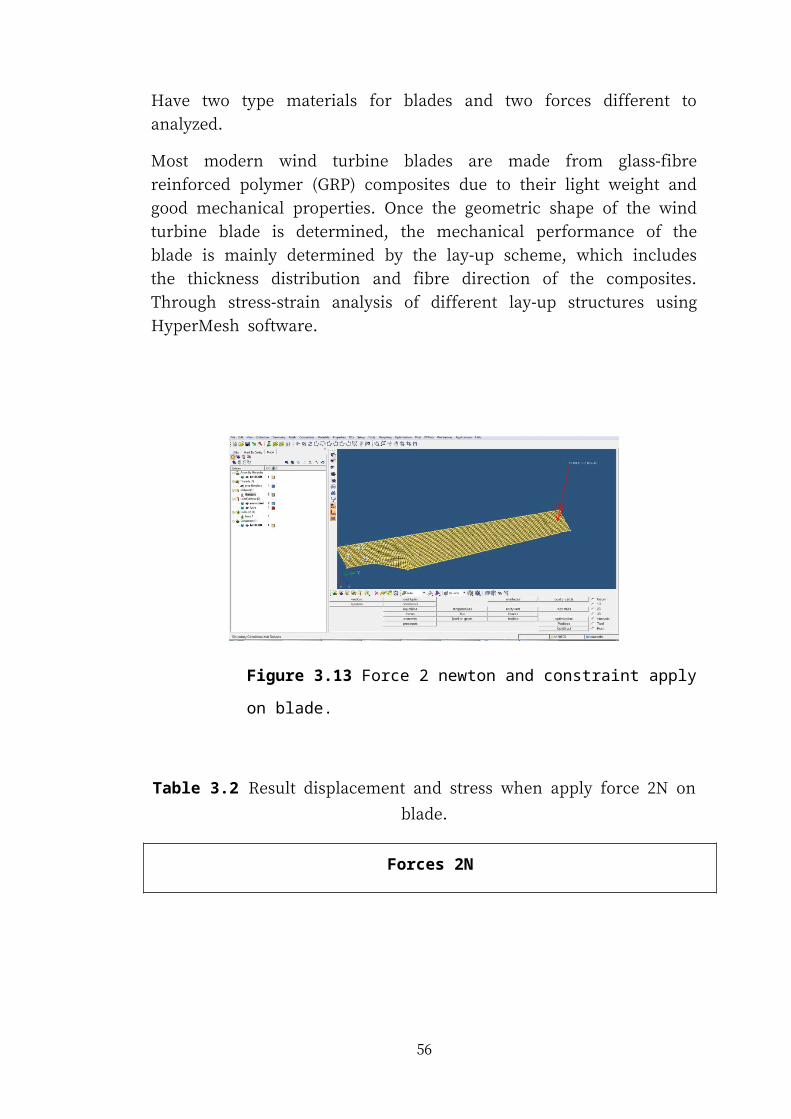
Figure 3.13 Force 2 newton and constraint apply on blade.
Table 3.2 Result displacement and stress when apply force 2N on blade.
Forces 2N
MaterialThickness
(mm)
Displacements
(mm)
Yield
Stress
(N/mm2)
Stress
(N/mm2)
Fib
er G
lass 3 Max =1.114 ×101
54.4
Max =1.381×101
4 Max = 4.733 Max = 7.411
5 Max = 2.442 Max = 4.740
Alu
min
ium
3 Max =7.135 ×10⁻³
20
Max = 1.430 ×101
4 Max =3.03 ×10⁻³ Max = 7.603
5 Max =1.566 ×10⁻³ Max = 4.818
49
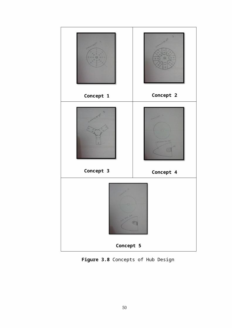
Figure 3.14 Force 5 newton and constraint apply on blade.
Table 3.3 Result displacement and stress when apply force 5N on blade.
Forces 5N
MaterialThickness
(mm)
Displacements
(mm)
Yield
Stress
(N/mm2)
Stress
(N/mm2)
Fib
er G
lass
3 Max =2.749 ×101
54.4
Max =3.431 ×101
4 Max =1.168 ×101 Max =1.842×101
5 Max = 6.029 Max =1.178 ×101
Alu
min
ium
3 Max =1.756 ×101
20
Max =3.631 ×101
4 Max = 7.471 Max =1.927 ×101
5 Max = 3.858 Max =1.213 ×101
50
REFERENCE
Austin. (2011). Blade materials. Adventures in Windpower, from
http://adventuresinwindpower.wordpress.com/2011/02/10/blade-materials/
Bagiorgas, H. S., Assimakopoulos, M. N., & Theharopoulos, D. (2006). Electricity
generation using wind energy conversion systems in the area of Western
Greece. Conversion and Management.
Blanton, J. T., & Preston, L. D. (2012). US 20120301310 A1.
Brondsted, P., Lilholt, H., & Lystrup, A. (2005). Composite materials for Wind
Power Turbine Blades (Vol. Volume 35).
Chena, K.-N., Gaub, W.-H., & Chena, P.-Y. (2011). Optimal Aerodynamic Design
and Material Layout of Composite Wind Turbine BladesKun-. Europe’s
Premier Wind Energy Event, PO. ID 470.
Darling, D. (2000). The Science of Flight.
Daut, I., Irwanto, & Irwan, M. (2011). Performace of Wind Turbine Based on Wind
Speed Data and Turbine Tower Height in Kangar, Northern Malaysia.
Retrieved from
http://connection.ebscohost.com/c/articles/69735026/performace-wind-
turbine-based-wind-speed-data-turbine-tower-height-kangar-northern-
malaysia
F.L Ponta, J. J. S., A.D. Otero. (2006). On the aerodynamics of variable-geometry
oval-trajectory Darrieus wind turbines. Renewable Energy.
Hansen, M. O. L. (2008). Aerodynamics of Wind Turbines: Earthscan LLC.
51
Harris, B. (1999). Engineering Composite Materials. Institute of Materials, London.
Hayashi, K., Hosoya, H., & Karikomi, K. (2010). EP 2187045 A1.
Ingram, G. (2011). Wind Turbine Blade Analysis using the Blade Element
Momentum Method.
ITDG, T. S. C., Fernando, S., & Piggott, H. (2001). Wind rotor blade construction.
Department for International Development, UK.
kiki. (2010). UPM-First Wind Turbine Hybrid with Solar Panel. Retrieved from
http://fannysoh.blogspot.com/2010/11/upm-first-wind-turbine-hydrib-
with.html
Lee, S. (2012, Thursday, April 26, 2012). Wind turbines as RE source, Daily
Express. Retrieved from http://www.thegreenmechanics.com/2012/04/wind-
turbines-as-re-source2.html
M.R. Islama, R. S., and N.A. Rahima. (2011). Assessment of wind energy potentiality
at Kudat and Labuan, Malaysia using Weibull distribution function (Vol.
Volume 36).
Meyers, C. B. (2012). Types of Wind Turbines, from
http://centurionenergy.net/types-of-wind-turbines
Othman, H. R. B. (2010). Wind Environment Evaluation on Major Town of
Malaysia. Bachelor of Civil Engineering, University Malaysia Pahang.
Ph. Devinant, T. L., J. Hureau. (2002). Experimental study of wind-turbine airfoil
aerodynamics in high turbulence. Journal of Wind Engineering and
industrial Aerodynamics.
52
Radhika. (2007, Tuesday September 25, 2007). Pulau Perhentian Kecil now powered
by the sun and wind, South & East, The Star online. Retrieved from
http://thestar.com.my/news/story.asp?file=/2007/9/25/southneast/18848088&
sec=southneast
Richardson, R. (2009). Wind Turbine Blade Composites Design.
Schubel, P. J., & Crossley, R. J. (2012). Wind Turbine Blade Design. Energies,
3425-3449, P 3427.
Shaharuddin, A. (2012, Thursday, 15 March 2012). Commercial wind energy
generation may be possible after all, alam post. Retrieved from
http://alampost.com/index.php?
option=com_content&view=article&id=373:commercial-wind-energy-
generation-may-be-possible-after-all&catid=67:energy&Itemid=392
Shed. (2010). Blade Materials Compared, from
http://www.thebackshed.com/windmill/articles/windyNationBladematerial.as
p
Somers, D. M., & Tangler, J. L. (1999). EP 0675285 B1.
Sunara, N. I. B. (2012). Design of Small Wind Turbine.
Tangler, J. L. (2000). The Evolution of Rotor and Blade Design. Palm Springs,
California.
Valencia, J. L. a. U. (2004). Design Studies for Twist Coupled Wind Turbine Blades
(pp. 46).
Walczyk, D. (2010). An Overview of Composite Wind Turbine Blade
Manufacturing, from http://www.docstoc.com/docs/75363654/An-Overview-
of-Composite-Wind-An-Overview-of-Composite-Wind
53
Wire, M. (2009, May 18, 2009). Efficient wind turbine blade design made from
composite materials. Retrieved from http://www.greendiary.com/efficient-
wind-turbine-blade-design-made-from-composite-materials-wins-
competition.html
Woofenden, I., & Piggott, H. (2012). Anatomy of a Wind Turbine, from
http://www.homepower.com/articles/anatomy-wind-turbine
Yusoff, I.-Y. (2006). The Suitability of Wind Generated Power for Home Power
Generation in Malaysia. Bachelor of Manufacturing Engineering (Honors)
(Manufacturing Process), Kolfli Universiti Teknikal Kebangsaan Malaysia.
54
55
APPENDIX A
1. Do you think the wind turbine help lower your energy problem?
Yes
No
2. What part you want to improve for generate more energy?
Blades
Generator
3. What do you expect from wind turbine blades?
Attractive
Good aerodynamic
Material selection
Other:
. .
4. What type material of wind turbine blades that you need?
Wood
Composite
Alluminium
5. What is the most important criteria of that wind turbine blade should have?
Lightweight
Smooth and silent
Cost
Durable
Easy to install
6. What is your suggestion to improve the energy capture of wind turbine?
56