report 11137 (p/n: 1331670-2, s/n: f01) - nasa · report 11137 4 may 1998 1.0 introduction this...
TRANSCRIPT
Report 11137
4 May 1998
Integrated
Advanced Microwave Sounding Unit-A (AMSU-A)
METSAT A1 Signal Processor Engineering Test Report
(P/N: 1331670-2, S/N: F01)
Contract No. NAS 5-32314
CDRL 207
Submitted to:
National Aeronautics and Space Administration
Goddard Space Flight Center
Grennbelt, Maryland 20771
Submitted by:
Aerojet
1100 West Hollyvale StreetAzusa, California 91702
https://ntrs.nasa.gov/search.jsp?R=19980218811 2019-02-03T18:03:35+00:00Z
Report 111374 May 1998
TABLE OF CONTENTS
1.0
2.0
3.0
4.0
5.0
6.0
INTRODUCTION ..................................................................... 1
OBJECTIVE ........................................................................... 1
TEST DATA ........................................................................... 1
TEST .................................................................................... 1
TEST ANOMALIES .................................................................. 5
TEST RESULTS ...................................................................... 6

Report 11137
4 May 1998
1.0 Introduction
This report presents a description of the tests performed, and the test data, for the A1 METSAT Signal
Processor Assembly PN: 1331670-2, SIN F01. The assembly was tested in accordance with AE-26754,
"METSAT Signal Processor Scan Drive Test and Integration Procedure".
The tests were conducted at room temperature in the AMSU-A test area of building 57. The tests fall into
six categories: 1) Continuity, 2) Power Distribution, 3) Digital Processor, 4) Analog Processor, 5) Scan
Drive, and 6) Supply Current.
2.0 Objective
The objective is to demonstrate functionality of the signal processor prior to instrument integration.
3.0 Test Data
All test data is presented on the enclosed copies of the test data sheets (TDSs) numbered A-2 through A-
14. Redlines to the data sheets were necessary and were accomplished in accordance with program
directive No. 91. Each change was approved by Quality and the test engineer. Changes were made for
the following reasons: 1) Notes were added to verify the test equipment and/or test setup was correct, 2)
Command instructions were clarified to remove any ambiguity in the instructions, and 3) Added and/or
removed steps to improve the test flow.
4.0 TESTS
4.1 Continuity
A complete continuity test of the backplane wiring is performed at the facility where the wirewrapping of
the backplane is done. The continuity tests performed here involve 1) the I/O interface card slots, J301and J326, 2) the Aerojet added Pre-amp/detector signal cable and connector, 3) the Aerojet added Pre-
amp/detector power cable and connector, and 4) chassis return connections. The tests are manual
resistance measurements tests. Test data is presented on TDS 1.
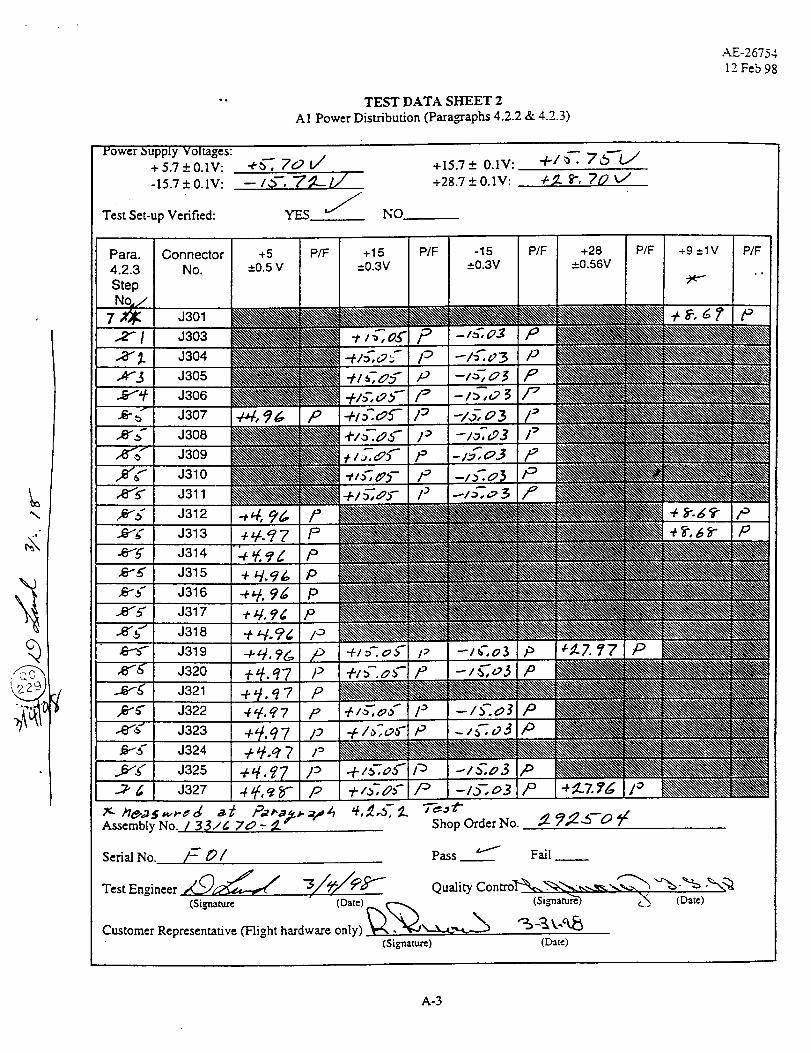
4.2 Power Distribution
In these tests supply voltages are input to the signal processor from the Test Relay Unit (TRU) as in
normal testing. No CCAs are installed in the signal processor for the tests. The test verifies that the four
supply voltages are present on the proper pins of all backplane connectors. The test setup block diagram
is shown in Figure 1, and test data is presented on TDS 2.

Report 11137
4 May 1998
J301 J326
A1 Signal Processor Assembly(PIN 1331670-2)
Current Meter(DMM)
Test Relay Unit (TRU)PIN SK1357278
+5V,+15V, +28V
Power Supply
Figure 1. A1 Signal Processor Test Setup
4.3 Digital Processor
Beginning with this test, CCAs are installed into the card cage as required to perform the test, and thenremain installed. At the conclusion of all tests, a complete set of CCAs has been installed. The completetest setup block diagram which is required for performing any of the tests is shown in Figure 2.
2

Report 11137
4 May 1998
J301
STE TO SIGNAL
JPROCESSOR INTERFACE
CABLE
(SK1359582)
STE
( 1356655-1 )
J326 J327
METSAT/AMSU-A1 SIGNAL PROCESSOR
(1331670-2)
TRU TO SIGNAL PROCESSOR INTERFACE CABLE (SK1359579)
TROI(SK1357278)
,_.... _b_-_ .....i RELAY AND
', HOUSEKEEPING
: CCA ',
+5V,:1:15V,+28V
POWER SUPPLY
CurrentMeter
(DAM)
3
//
=_ EXTENDERCARD
SCAN DRIVE
INTERFACE
CABLE
(SK1358395)
!I
I
J
I UPPER 1
. CARD CAGE ,
i FIXTURE _i (SK1359646)
L JCAB1-3
R1-R2. S1-S3 S2-$4
MOTOR DRIVER TEST FIXTURE
(SK1293785)
MOTOR DRIVER ADAPTOR INTERFACE CABLE (SK1358701)
25 D*Type
ector
ADAPTOR BOX
4-3 HALL SENSOR
(SK1358259)
J1
MOTOR ASSEMBLY (P/N SK1358657)
4 HALL SENSORS
MOTOR
RESOLVER
m
m
INERTIA DISK
Figure 2 Scan Drive Test Set-Up
Report 11137
4 May 1998
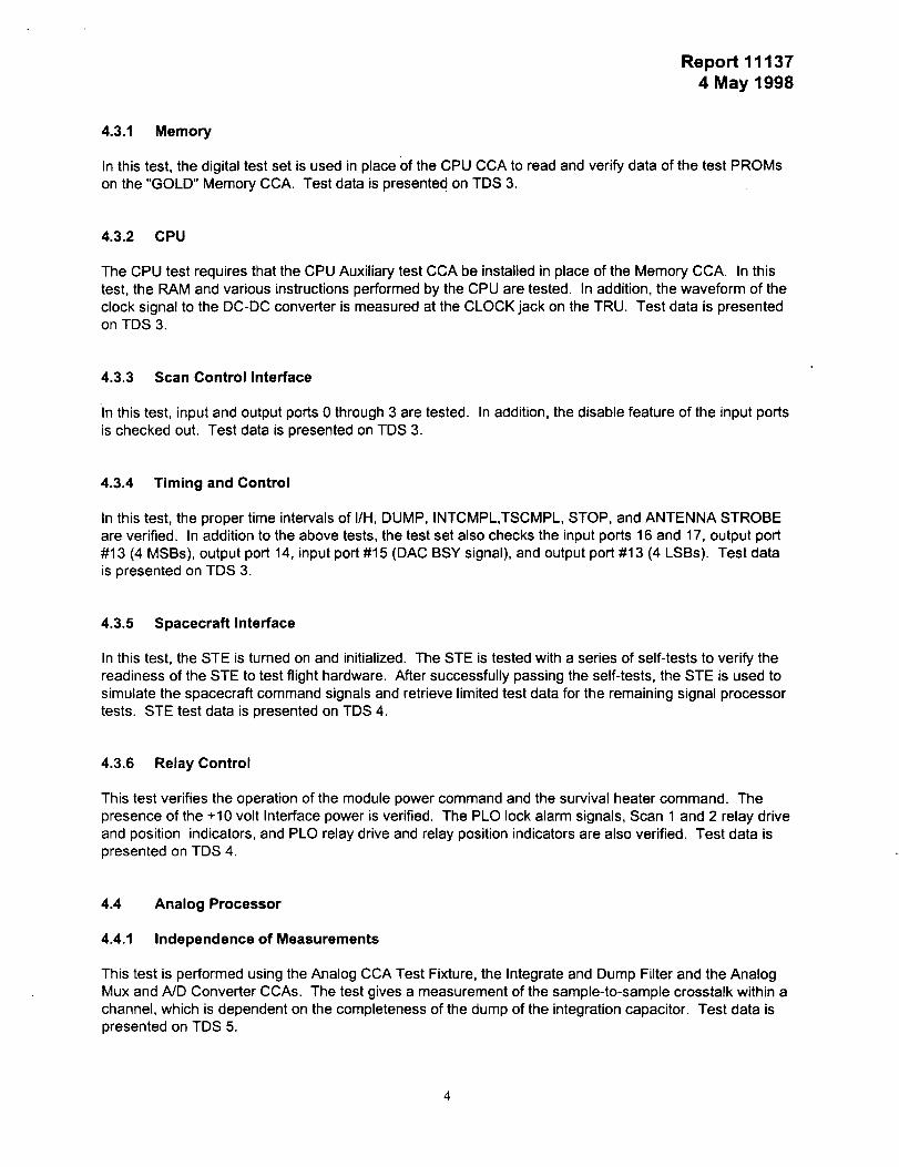
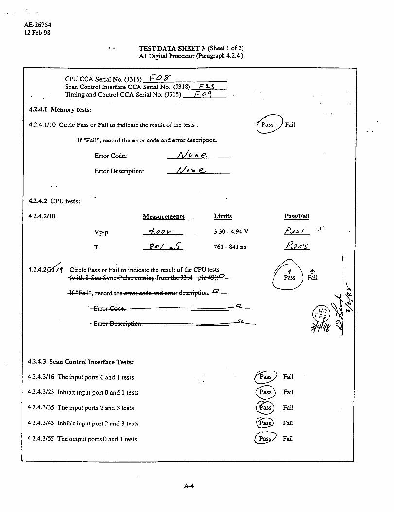
4.3.1 Memory
In this test, the digital test set is used in place of the CPU CCA to read and verify data of the test PROMs
on the "GOLD" Memory CCA. Test data is presente d on TDS 3.
4.3.2 CPU
The CPU test requires that the CPU Auxiliary test CCA be installed in place of the Memory CCA. In this
test, the RAM and various instructions performed by the CPU are tested. In addition, the waveform of the
clock signal to the DC-DC converter is measured at the CLOCK jack on the TRU. Test data is presentedon TDS 3.
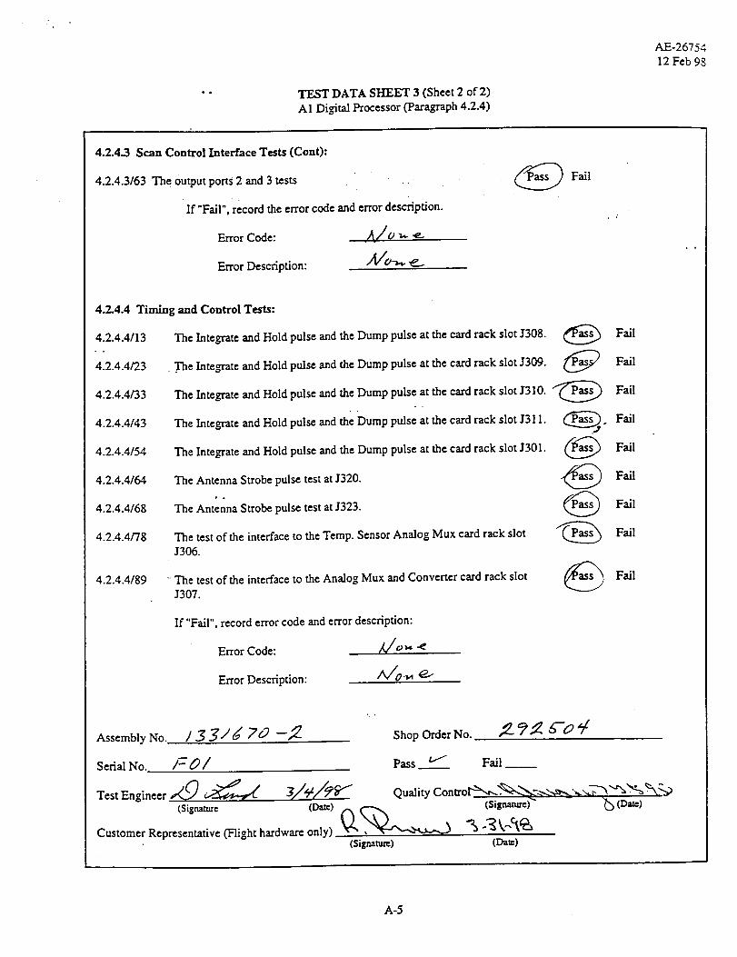
4.3.3 Scan Control Interface
In this test, input and output ports 0 through 3 are tested. In addition, the disable feature of the input ports
is checked out. Test data is presented on TDS 3.
4.3.4 Timing and Control
In this test, the proper time intervals of I/H, DUMP, INTCMPL,TSCMPL, STOP, and ANTENNA STROBE
are verified. In addition to the above tests, the test set also checks the input ports 16 and 17, output port
#13 (4 MSBs), output port 14, input port #15 (DAC BSY signal), and output port #13 (4 LSBs). Test data
is presented on TDS 3.
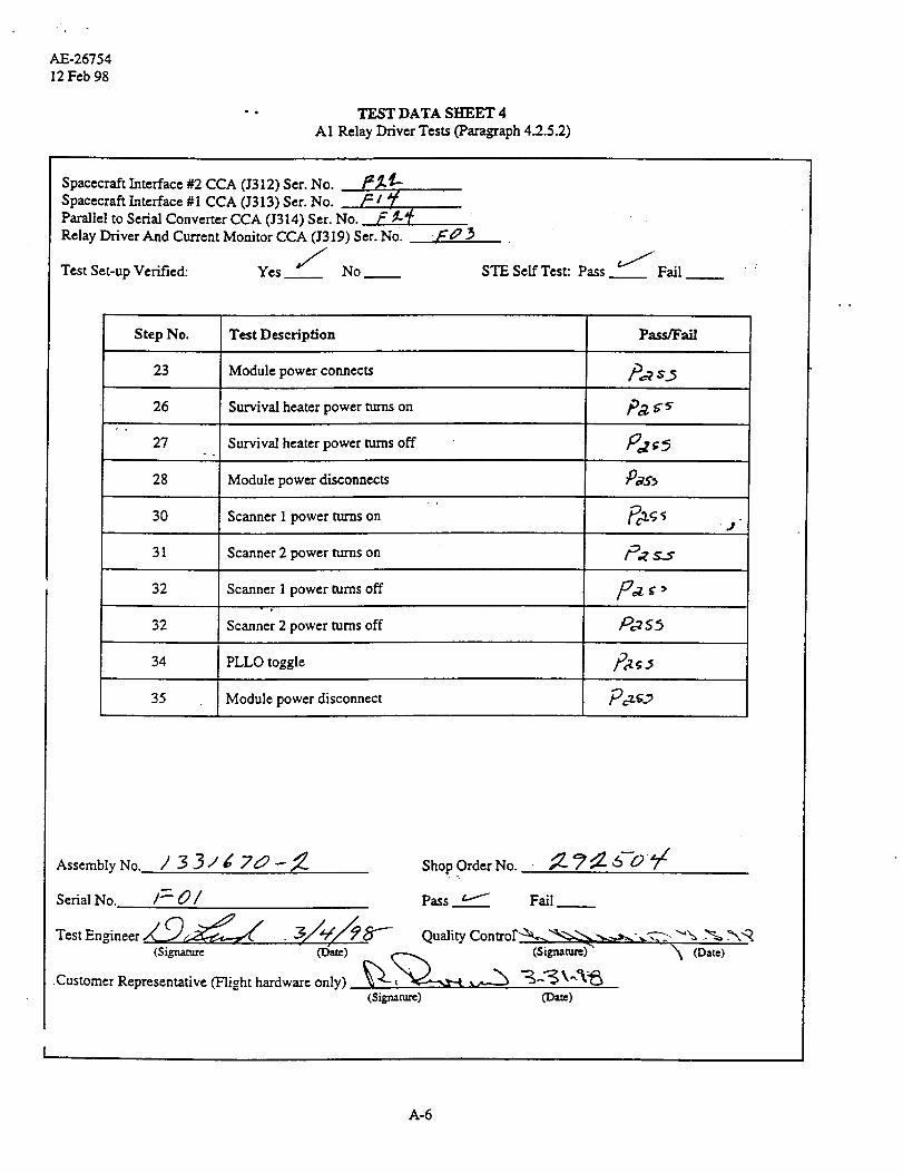
4.3.5 Spacecraft Interface
In this test, the STE is turned on and initialized. The STE is tested with a series of self-tests to verify the
readiness of the STE to test flight hardware. After successfully passing the self-tests, the STE is used to
simulate the spacecraft command signals and retrieve limited test data for the remaining signal processor
tests. STE test data is presented on TDS 4.
4.3.6 Relay Control
This test verifies the operation of the module power command and the survival heater command. The
presence of the +10 volt Interface power is verified. The PLO lock alarm signals, Scan 1 and 2 relay drive
and position indicators, and PLO relay drive and relay position indicators are also verified. Test data ispresented on TDS 4.
4.4 Analog Processor
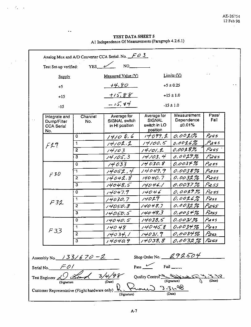
4.4.1 Independence of Measurements
This test is performed using the Analog CCA Test Fixture, the Integrate and Dump Filter and the Analog
Mux and A/D Converter CCAs. The test gives a measurement of the sample-to-sample crosstalk within a
channel, which is dependent on the completeness of the dump of the integration capacitor. Test data ispresented on TDS 5.
Report 111374 May 1998
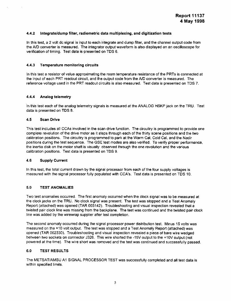
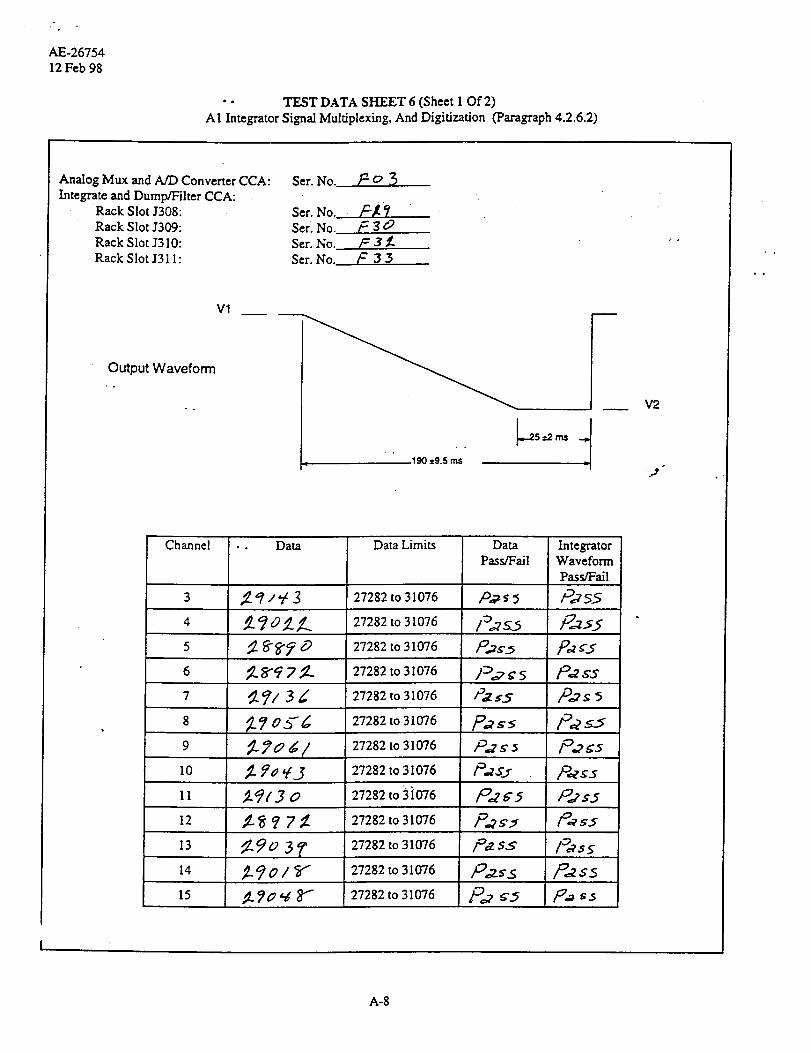
4.4.2 Integrate/dump filter, radiometric data multiplexing, and digitization tests
In this test, a 2 volt dc signal is input to each integrate and dump filter, and the channel output code from
the ND converter is measured. The integrator output waveform is also displayed on an oscilloscope forverification of timing. Test data is presented on TDS 6.
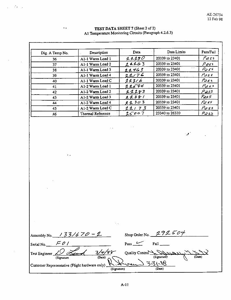
4.4.3 Temperature monitoring circuits
In this test a resistor of value approximating the room temperature resistance of the PRTs is connected at
the input of each PRT readout circuit, and the output code from the A/D converter is measured. The
reference voltage used in the PRT readout circuits is also measured. Test data is presented on TDS 7.
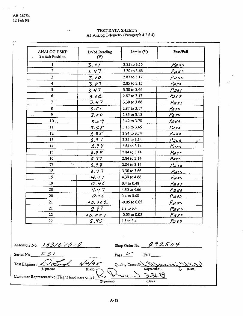
4.4.4 Analog telemetry
In this test each of the analog telemetry signals is measured at the ANALOG HSKP jack on the TRU. Test
data is presented on TDS 8.
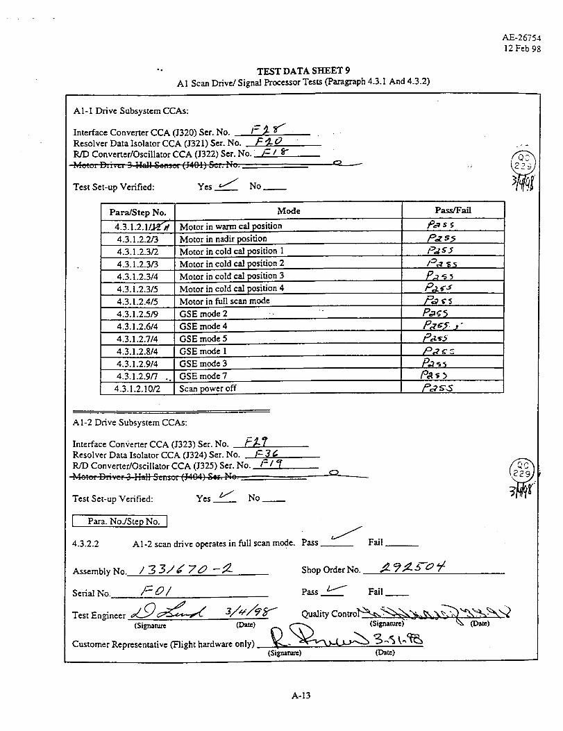
4.5 Scan Drive
This test includes all CCAs involved in the scan drive function. The circuitry is programmed to provide one
complete revolution of the drive motor as it steps through each of the thirty scene positions and the two
calibration positions. The circuitry is programmed to park at the Warm Cal, Cold Cal, and the Nadir
positions during the test sequence. The GSE test modes are also verified. To verify proper performance,
the inertia disk on the motor shaft is visually observed through the one revolution and the various
calibration positions. Test data is presented on TDS 9.
4.6 Supply Current
In this test, the total current drawn by the signal processor from each of the four supply voltages is
measured with the signal processor fully populated with CCA's. Test data is presented on TDS 10.
5.0 TEST ANOMALIES
Two test anomalies occurred. The first anomaly occurred when the clock signal was to be measured at
the clock jacks on the TRU. No clock signal was present. The test was stopped and a Test Anomaly
Report (attached) was opened (TAR 003142). Troubleshooting and visual inspection revealed that a
twisted pair clock line was missing from the backplane. The test was continued and the twisted pair clock
line was added by the wirewrap supplier after test completion.
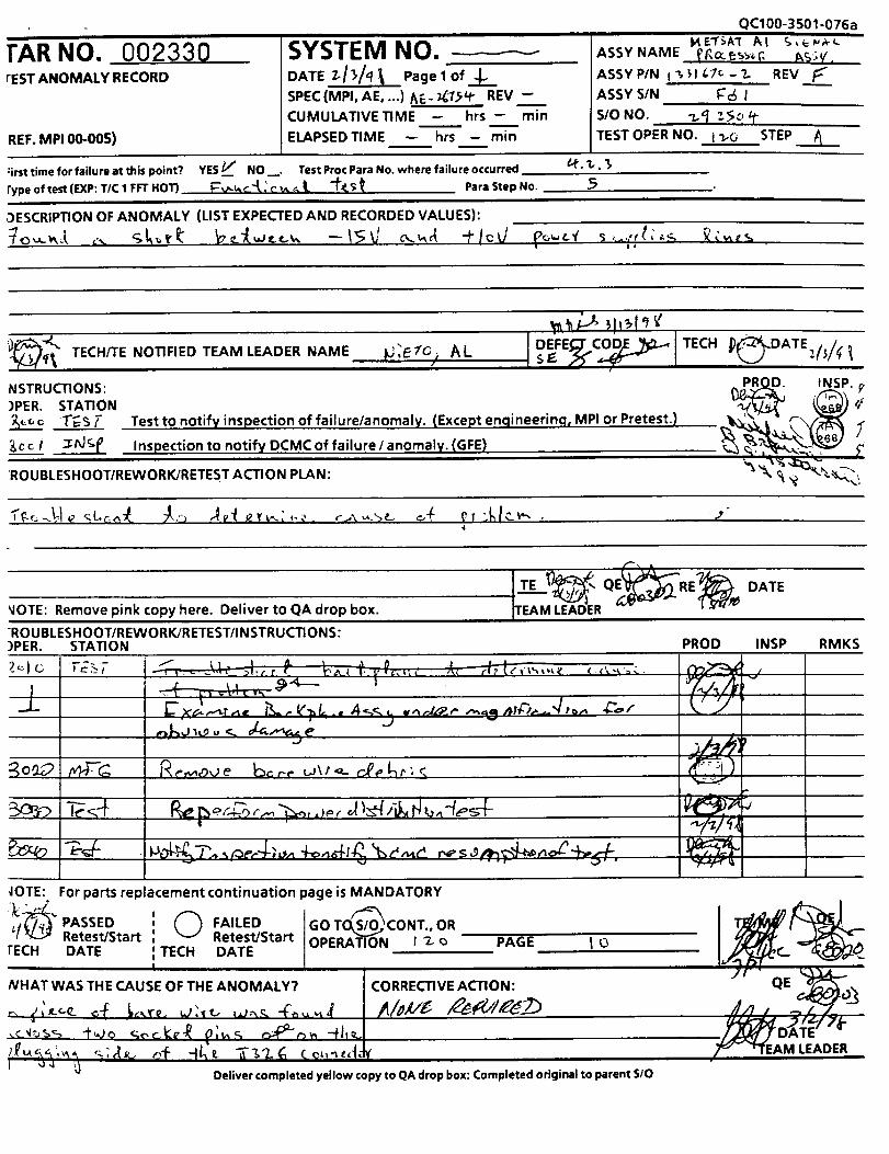
The second anomaly occurred during the signal processor power distribution test. Minus 15 volts was
measured on the +10 volt output. The test was stopped and a Test Anomaly Report (attached) was
opened (TAR 002330). Troubleshooting and visual inspection revealed a piece of bare wire wedged
between two sockets on connector J326. This wire shorted the -15V output to the +10V output (not
powered at the time). The wire short was removed and the test was continued and successfully passed.
6.0 TEST RESULTS
The METSAT/AMSU A1 SIGNAL PROCESSOR TEST was successfully completed and all test data is
within specified limits.

AE-26754
12 Feb 98
TEST DATA SHEET 1
A1 Continuity Tests (4.2.1)
From To Signal Name Pass/Fail
•J301-1 P511-3 CH 3 - IN
J301-10
2"301-13
J301-15
2"301-16
J301-19
J301-21
J301-22
J301-25
I301-3
J301-4
J301-60
CH S-INP511-13
P511-15 CH 9 - IN
P511-17 CH 10 - IN
P511-19 CH I1 - IN
P511-21 CH 12 - IN
P511-23 CH 13 -IN
P511-25 CH 14 - IN
P511-1 CH 15 - IN
P511-5 CH 4 - IN
P511-7 CH 5 - IN
E1 CHASSIS GND
J301-7 -" P511-9 CH 6 - IN
J301-9 P511-11 CH 7 - IN
J301-90 E2 CHASSIS GND ""
J304-43 P512-5
J304 -45 P512-24
J304-46 P512-9
J304-48 P512-29
J304-49 P512-14
J304-51 1>512-15
2"305-68 P512-12
+15V(2)
+15V(2)
15VRTN(2/3)
15VRTN(2/3)
PRT35_HI (PRE AMP)
/og 4.5
/t:,:s:
/::',,.7s_
Pas _,
P,7 _a"
P_s#
P_
- 15V(3) /O.,Z _r
- 15V(3) p,,_ _
J305-72 P512-11 PRT35_LO (PRE AMP) /_,2 _r_
J326-76 E3 CHASSIS GND l_.Z $_
Assembly No. / 3 3 / _' 7 _9 -- _- Shop Order No. ¢_- Y: _'--0
Serial No. /-_0 / Pass _ Fail __
Test En_neer ,__ _/f//'_"" Quality ControI"----_,_i;._'_,._-_._"_..__"_ -_'u _N,_
Customer Representative (Flight hardware only) \_-'__ "_ "_ \"_k_
(Signature) (lYa,_)
A-2
TEST DATA SHEET 2
A1 Power Distribution (Para_aphs 4.2.2 & 4.2.3)
AE-26754
12 Feb 98
Yower bupply Voltages:+5.7 +0.1V:-15.7__0.iv: - :_. 7_.--t/"
Test Set-up Verified: YES "_ NO
.e_ ;,cat/ +/C 7 o'cJ
+j__-, 7_i
A-3
AE-2675412Feb 98
TEST DATA SHEET 3 (Sheet 1 of 2)
A1 Digital Processor (Paragraph 4.2.4 )
CPU CCA Serial No. (J316) /_O oe"
Scan Control Interface CCA Serial No. (J318) /: _-_
Timing and Control CCA Serial No. (J3 I5) /"- O '_
4.2.4.1 Memory tests:
4.2.4.1/10 Circle Pass or Fail to indicate the result of the tests :
4.2.4.2 CPU tests:
4.2.4.2/10
If "Fail", record the error code and error description.
Error Code: ]_/'0-_
Error Description: /ie/a_ _--
Measurements . .
Vp-p _. o o w"
Circle Pass or Fail to indicate the result of the CPU tests
"-(;;'i-k o Scc Syr, c-2._Isc. --a,,r,--_,, ," ........ '_"_
Ar -_:,;i,,, ..... A ,,,, -'-;or cA .a ::':c,r dczci_p_cr,.
-- I::_,._ ¢"_A_
Limits
3.30 - 4.94 V
761 - 841 ns
4.2.4.3 Scan Control Interface Tests:
4.2.4.3/16 The input ports 0 and 1 tests
4.2.4.3/23 Inhibit input port 0 and 1 tests
4.2.4.3/35 The input ports 2 and 3 tests
4.2.4.3/43 Inhibit input port 2 and 3 tests
4.2.4.3/55 The output ports 0 and 1 tests
Fail
Pass/Fail
..¢-y .A'
Fail
Fail
(_ Fail
(_ Fail
(_ Fail
) Fail
A-4
TEST DATA SHEET 3 (Sheet 2 of 2)
A1 Di#tal Processor (ParagTaph 4.2.4)
AE-26754
12 Feb 98
4.2.4.3 Scan Control Interface Tests (Cont):
4.2.4.3/63 The output ports 2 and 3 tests
If "Fail", record the error code and error description.
Error Code: /_/O "_- c--
Error Description: ,_O-_
Fail
4.2.4.4 Timing and Control Tests:
4.2.4.4/13
4.2.4.4/23
4.2.4.4/33
4.2.4.4/43
4.2.4.4/54
4.2.4.4/64
4.2.4.4/68
4.2.4.4/78
4.2.4.4/89
The Integrate and Hold pulse and the Dump pulse
.The Integrate and Hold pulse and the Dump pulse
The Integrate and Hold pulse and the Dump pulse
The Integrate and Hold pulse and the Dump pulse
The Inte_ate and Hold pulse and the Dump pulse
The Antenna Strobe pulse test at J320.
The Antenna Strobe pulse test at J323.
at the card rack slot ]'308. _ Fail
at the card rack slot ]'309. _ Fail
at the card rack slot ]'310. _ Fail
at the card rack slot ]'311.
at the card rack slot J301.
The test of the interface to the Temp. Sensor Analog Mux card rack slot
J306.
" The test of the interface to the Analog Mux and Converter card rack slot
J307.
. Fail
Fail
Fail
Fail
Fail
Fail
If "Fail", record error code and error description:
Error Code: /(,/'o,4 .e
Error Description: A¢/O "_ _
Assembly No. / _ 2, / b/ 70 --.,_
serialNo /= O /
Test En_neer _..,._ _ 3//C/_.
Customer Representative (Flight hardware only)(Signature)
ShopO derNo. ?,¢. 4
Pass_ t...." Fail
Quality Con tro_ ._ -"z-,_'_--_ "%'_ _%_(Signature) - "_ (Date)
(Date)
A-5
AE-2675412Feb98
TEST DATA SI{EET 4
AI Relay Driver Tests (Paragraph 4.2.5.2)
Spacecraft Interface #2 CCA 0312) Ser. No. _._
Spacecraft Interface #1 CCA (J313) Ser. No. /=/_t
Parallel to Serial Converter CCA (I314) Ser. No. /c_.,_
Relay Driver And Current Monitor CCA (J319) Ser. No.
/Test Set-up Verified: Yes _ No
,FO._
JSTE Self Test: Pass Fail
Step No. Test Description Pass/Fail
23 Module power connects /3¢_ $.5
26 Survival heater power turns on
• °
27 Survival heater power turns off
28 Module power disconnects
30 Scanner 1 power rams on
31
32
Scanner 2 power turns on
Scanner 1 power turns off
Scanner 2 power turns off
_-_r
P_5
_aS_
32 P:S5
34 PLLO toggle ]-99,_;
35 Module power disconnect P_._
Assembly No. ,] 33J_/ 70--_.
Serial No. )_ 0 /
Test Engineer,,_c__
(Signature
Customer Representative (Flight hardware only)
i"- z./"Shop_derNo. 2--?_ oat
Pass. _ Fail
•_,/,,,'/'_er--- Qual_co._oV_.._'-_,,,.-.-_,-_ "-.',-_ ._" (Dam)" r,. _---_,_. (Sigrmtttm)_" "_ (Date)
(Si_atane) O::_a')
A-6
7
AE-26754
12 Feb 98
TEST DATA SHEET 5
A1 Independence Of Measurements (Paragraph 4.2.6.1)
Analog Mux and A/D Converter CCA Serial. No. /-_ O 3
Test Set-up verified: YES J NO
Measured Value (V)
+5 +%8"o
+]s -e/_ 8"g"
-15 - _6"7.q4
Limits fV')
+5 __-0.25
+15 --+1.0
-15 __.1.0
Integrate andDump/FilterCCA SerialNo.
F_o
Channel
0
2
3
0
I"1
2
3
0
1
2
3
Average forSIGNAL switch
in HI position
/,//o B, L
/_/10 3
/_/o.¢, 3
/_033
Average forSIGNAL
switch in LO
position
/,//o0, 6-
/ _z/o/, _.
/,//o3, "/
/./03o. g
///o qO, 7
/"/Z9 "/_', /
Measurement
0
1
,m 3.._ 2
3
Dependence_<0.01%
o,ooO.d_o
o, oo_ _
0,0o_
o, o o Z _'.ego
o, oo 30.
o,0o37._o
/4o_,7. ?
NO.
/,,zo ,,,z_/ O, o o _ _.._o
/"/03o, 7 / *10 ,_ =/ O, o o .I_w1._o
/ _03-0, 8 /,,/o,'/ a', 7 o, 0 o5,_ ._
/ ,/ o _-o, ..5- / _ o /./8",3 o, o o 3 _ ._o
/.7'0 _ E / 6z 0 ,/,$7 8 0 ,o o 3 _ _
/_zo 3_Z/ /_za5/, ? o,_o_) ./o,'/0, _ /_cO_, E 0.oo_._
Pass/
Fail
P_¢s
.P._ _ s
Pa cs
IPa _s
P.a_s
P._ss
)°,ass
/D.ZCS"
Pa _S
P,.,7 _,$
Assembly No. / Z 3/' _" 70 -- _-
Serial No. ]= 0 /
(Sigr_atttre (Date)f_
Customer Representative (Flight hardware only) _x.,(Signature)
Shop Order No.
,....--"Pass Fail
Quality Contro_,.-, ._" .--_ _ "% 2% ._x'-2(Si_tur=) _ (Date)
(D_)
A-7
°
AE-26754
12 Feb 98
• • TEST DATA SHEET 6 (Sheet l Of 2)
Al Integrator Signal Multiplexing, And Digitization (Paragraph 4.2.6.2)
Analog Mux and A/D Converter CCA:
Integrate and Dump/Filter CCA:Rack Slot J308:Rack Slot J309:
Rack Slot J310:
Rack Slot J311:
Ser. No. F 0 3
Ser. No. /t:] 7
Set. No. t_ :3OSer. No. t_ 3 _.
Ser. No. F 3 5
V1
Output Waveform
Channel •. Data Data Limits
:t f;_.y o
Data
Pass/FailIntegratorWave form
Pasa/l::ail
/°ws-_
/9_ 553 fl.q/-/3 27282 to 31076 P.,_ _ 5
4 _ ? O_,_... 27282 to 31076 /Z_TS 5 /-_,5 5
5 27282 to 31076
__y o_
6 _ _f'q 7 _-- 27282 to 31076 ,/_,_ ¢ 5 /o; $.5"
7 _[_/ 3 _ 27282 to 31076 /-°Xs5 /DoT_ 5
8 27282 to 31076
5-?OLl
_-q/3 o
10
11
12
13
14
27282 to 31076
27282 to 31076
27282 to 3i076
27282 to 31076
27282 to 31076
27282 to 31076
27282 to 3107615
¢_97_
_$5
P.I _ 3
l_ s5
]-7,,7__ S
Zgo3f9-qo/_
p..yv,_ 8"
_.P G5
P._ s5
/°_ s 5
I_ss
V2
Y,
• o
A-8

°
TEST DATA SHEET 6 (Sheet 2 Of 2)
AI Integrator Signal Multiplexing, And Digitization (Paragraph 4.2.6.2)
AE-26754
12 Feb 98
Signal Name Output Output Return Signal Levels Pass/Fail
I/H J301-42 J301-41 Pulses (TI'L) /-_ a
Dump J301-45 J301.-41 Pulses (TTL) /gj_,,j . ,
+5 Vdc GSE Interlock A I301-61 J301-70 +5 V P_ _5
+5 Vdc GSE Interlock B J301-62 J301-70 +5 V /D_
Assembly No. / _ ._ / _ y__._9 -- _. "
sedal No. ,Z::O /
(Signatu_ (Date) _ (Signature)\l _ ,.
-%Customer Representative (Flight hardware only) _--,_
(Si_arare) (Da_)
Shop Order No. _. _ _ _"'_ z./'
Pass. _ Fail__
Quality Control'"N___.._" _ _ ,'_,-,.,9
A-9

AE-26754
12 Feb 98
TEST DATA SHEET 7 (Sheet 1 of 2)
A1 Temperature Monitoring Circuits (Paragraph 4.2.6.3)
Temperature Sensor A CCA0"303) Serial No. /_ O
Temperature Sensor B CCA (J304) Serial No. F ;_""
Temperature Sensor B CCA (J305) Serial No../c_.g
Temperature Sensor Analog Mux CCA 0306) Serial No.
Dig. A Temp No.
1
9
I0
11
12
Description
Scan Motor AI-1
Scan Motor AI-2
Feedhom AI-1
Feedhom A 1-2
RF MLIX AI-1
Dam
"g/ 9..3 _-
3o_o4
RF MU'X A I-2 3 0 76"_,
LOCH3 3o7& at"
LOCH4
LO CH 5
LO CH 6
LOCH7
LO CH 8
3oF 3.__
"3/03/
Jo6"g
Data Limits
F]/_ ---"-
Pass/Fail
28259 to 32513 /_R_
28259 to 32513 P,_ 85
28259 to 32513 P_'/_'S
28259 to 32513
28259 to 32513
28259 to 32513 ,P_ S S
28259 to 32513
28259 to 32513
28259 to 32513
28259 to 32513
28259 to 325 13
28259 to 32513
13 LO CH 15 30 73 / 28259 to 32513
14 PLO #2 3 oB_O 28259 to 32513
15 PLO #I 3 o _ '_' 28259 to 32513
16 N'/A _ tJ//_
ff_cS;
_s5
O _'_ _: 28259 to 32513
3 o ?_ 28259 to 32513
J o _'/5"-" 28259 to 32513
3 / 0,5"-O 28259 to 32513
5 O 7"/3 28259 to 32513
5 063 0 28259 to 32513
O _'3 3 28259 to 32513
3'Q _¢5-'_ 28259 to 32513
o _'@ 7 28259 to 32513
/ O 3_' 28259 to 32513
3a _'8/ 28259 to 32513
3 0'_ _ _, 28259 to 32513
o _'I_"" 28259 to 32513
30 9'5+'*/ 28259 to 32513
3o 7_._ 28259 to 32513
,_0 _ b-- 3 28259 to 32513
3/0 7 / 28259 to 32513
_0_ 7 _ 28259 to32513
_'/0 _ 28259 to 32513
17 Mixer IF CH 3 p,_¢._
18 Mixer IF CH 4 t°_s s
19 Mixer IF CH 5 /_¢ s
20 Mixer IF CH 6 /_ _'5
21 Mixer IF CH 7 _.v ¢
22 Mixer IF CH 8 _ s)
23 Mixer IF CH 9/14 P2$ .s
Mixer IF CH 1524
25 IF Amp CH 11/14 P2_ )
26 IF Amp CH 9 P,.7¢_
27 IF Amp CH 10 P_-_'a
28 IF Amp CH I 1
29 DC/DC Cony
IF Amp CH 133O
31 IF Amp CH 14
32
33
34
IF Amp CH 12
R.F Shelf AI-1
RF Shelf A1-2
35 Detector/Preamp
P_s_
/O._ss
Fo_s )
0 L,_,..
]w/
A-10
TEST DATA SHEET 7 (Sheet 2 of 2)
A1 Temperature Monitoring Circuits (Paragraph 4.2.6.3)
AE-26754
12 Feb 98
Dig. A Temp No. Description
36 AI-1 Warm Load 1
37 A 1-1 Warm Load 2
38 AI-I Warm Load 3
39 AI-1 Warm Load 4
40 AI-1 Warm Load C
41 A1-2 Warm Load 1
42 A1-2 Warm Load 2
43 A1-2 Warm Load 3
44 A 1-2 Warm Load 4
45 AI-2 Warm Load C
.4.6 Thermal Reference
_ 3o3
_._./ 7_
_.ff-o o 7
20339 to 23401
20339 to 23401 P,? s-s
20339 to 23401
23340 to 26320
Io.7, K _
P_g g.5
r
Assembly No. ,/_ 3/6 j7_9 -- _._ Shop Order No.
Serial No. _ 0 / Pass _ Fail
Test En_neer
(Signature (Date,_,__Customer Representative ('Flight hardware only)
(Signature)
Quality Contro_.,_q_,._,,,.__x.\. _-'_ _k"_
(signat_'% - - -(_ (Date)
(Dam)
A-11
AE-2675412Feb 98
TEST DATA SHEET 8
A1 Analog Telemetry (Paragraph 4.2.6.4)
ANALOG HSKP
Switch Position
1
2
3
4
5
6
7
DVM Reading
O r)
3. a/
3."/'7
"J. 03
3, q7
8 g.ol
-. 9
Limits O r)
l0 ..
- 11
12
13
14
15
16
g._7
2.85 to 3.15
3.30 to 3.66
2.87 to 3.17
2.85 to 3.15
3.30 to 3.66
2.87 to 3.17
3.30 to 3.66
2.87 to 3.17
Pass/Fall
/Oo7_5
P.,a s s
P,O $5
_fs._. oo 2.85 to 3.15
3. o"_ 3.42 to 3.78 _oass
3, if- tY" 3.13 to 3.45 l_as5
2. e_ _ 2.84 to 3.14 Pa s_
2.84 to 3.14
2.84 to 3.14
2.84 to 3.14
2.84 to 3.14
2.84 to 3.14
3.30 to 3.66
5.. ?'/
17 "- ;_._ F
18 ..Z. "/7
19
Pass
P,,_ s s
Pass
_t, ,.[ 7 4.30 to 4.66
19 0. "/L 0.4 to 0.48 /_,_ $
20-- _¢- '/7 4.30 to 4.66 P,_ _5
20 O."_ _ 0.4 to 0.48
40, o o _-. -0.05 to 0.05
2.8 to 3.4
-0.05 to 0.05
2.8 to 3.4,_, _
21
21
22
22
PaS._
P,_$$
AssemblyNo. ,/5.._/'_ ,7_,9 --__. Shop Order No. ,_ ?_...6""0 9 /
Scrim No. /_-- 0 / Pass b-'" Fail __
(Signature (Date) _ _ (Signature'S-.,.- _ (Date)
Customer Representative (Flight hardware only) k'_'_ _ "_'_ "_
(Si_ature) (Date)
A-12
TESTDATASHEET 9
A1 Scan Drive/Signal Processor Tests (Paragraph 4.3.1 And 4.3.2)
AE-26754
12 Feb 98
A1-1 Drive Subsystem CCAs:
Interface Converter CCA 0320) Ser. No. 1-- _- _'/
Resolver Data Isolator CCA 0321) Ser. No. F _- O
R/D Converter/Oscillator CCA 0322) Ser. No. /_ /_I .... D21v_,t "_ IL/.]I e .................
Test Set-up Verified: Yes __"/ No_
@
Para/Step No.r
4.3.1.2.1/_d
4.3.1.2.2/3
4.3.1.2.3_
4.3.1.2.3_
Mode
Motor in warm cal position
Motor in nadir position
Motor in cold cal position 1
Motor in cold ca] position 2
4.3.1.2.3/4 Motor in cold ca] position 3
4.3.1.2.3/5 Motor in cold ca] position 4
4.3.1.2.4/5 Motor in full scan mode
4.3.1.2.5/9 GSE mode 2 ..
4.3.1.2.6/4 GSE mode 4
4.3.1.2.7/4 GSE mode 5
4.3.1.2.8/4 GSE mode 1
4.3.1.2.9/4 GSE mode 3
4.3.1.2.9_ ..
4.3.1.2.10_
GSE mode 7
Scan power off
Pass/Fail
_c_S5
p_ S5
Pdg._
/_ _
Pe '5 .,"
/°,_ s'.S
A 1-2 Drive Subsystem CCAs:
Interface Converter CCA 0323) Ser. No. Ffl-'_
Resolver Data Isolator CCA 0324) Ser. No. /-.7._RID Converter/Oscillator CCA (J325) Ser. No. 1--"l '_
Test Set-up Verified: Yes _ No_
O "--------------
[ Para. No/Step No. I
4.3.2.2 A1-2 scan drive operates in full scan mode. Pass Fail
Assembly No. / _ 3,,/_ / 7_ --_-- Shop Order No. ,_- _,_" _'-"_ 92
Serial No. /_ _/ Pass. _ Fail
Test Zn_neer ,__ 3//q"/_ _'" Quality Contro_2-N-_['_"_,.- _,\_ _-_'_'_ "-_',-:"_2_-"_N'Q
(Signatam (Date) (Sigr_anu_...... %, (Date)
Customer Representative (Flight hardware only) _._._ '_ .-.'_ ,,,'_:i_
(Si**-aat_) (Date)
A-13

AE-2675412Feb98
TEST DATA SHEET 10
A1 Supply Currents (Paragraph 4.4)
Voltages Measured Current Limits (in mA) Pass/Fail
+28.7V 6 to 12 pals 5
+5.7V7,79"e, 700 to 1642
+15.7V 152 to 364
-15.7V / 9L9 162 to 381Pa sPe s-_
Assembly No.
(Signature (Date)
Customer Representative (plight hardware only) __
(Sig-namrc)
Shop Order No. "2.-_ 2, ._ 0
/Pass Fail
(Signature) _ace)
(Dr-)
A-14

TAR NO. 003142TEST ANOMALY RECORD
',REF. MP100-005)
i
SYSTEM NO.o,_L_
SPEClMPJ.__.g...)Z,7_',/ REV,-'-CUMULATIVETIME _ hrs --- rain
ELAPSED TIME --- hrs _ mm
QC100-3501-O76a
ASSY NAME -_/_AJA_- P_o_._---_¢_:_
ASSY P/N/.33//.pTo--Z, REV
ASSY S/N _/
S/O NO. "Z-92._-0
TEST OPER NO. _,_o STEP,_v.:_-,v¢:,. i
Firsttimeforfailureatthispoint7 YESIJ NO. TestProcParaNo. where failure occurred _/_o_--. _-
Type of test(EXP:T/C1 FFTHOT) "f_-_'7" /o_ ____EZ)/Jl_" Jl::J_:k_/A/_ ParaStep No. / ,9
DESCRIPTION OFANOMALY (LIST EXPECTED AND RECORDED VALUES): /1/'0 _z-OaC._- S/_"A/_/-- _--7 _
c _o_,_ :_c/-_ _ "2"_ U. .-<_ou_,'_ _ ...y. _ _-_ ,./-, _ _z .V. ,'_''-,_';cj,'_z_-._ "z_-,e,_..,
T I..'_/
TIFIED TEAM LEADER NAME _<_. e_y'l'_"?_'_ N FV _ t/¢_'_;_ '_;
NSTRUCTIONS:
:)PER. STA TI ON, _.r__-_..._.--Tjlu¢4 $/J Test to notify inspection of failure/anomaly. (Except enqineerin.c h MPI or Pretest.)
_x_L/_ //_ iI_ Inspection to notify DCMC of failure / anomaly. (GFE) t;_c_-_,/[/_
"ROUBLESHOOT/REWORK/RETEST ACTION PLAN:
-7-_'_ t_/_Jz_¢ z_____,<_ -_ - -9"_
I TE _1_'_ r_-__ F_(_/'DATE
NOTE: Remove pink copy here. Deliver to QA drop box. ITEAM LEADER VC_' _/T ?'
TROUBLESHOOT�REWORK�RETEST�INSTRUCTIONS::)PER. STATION PROD INSP RMKS
^
NOTE: For parts replacement continuation page is MANDATORY
PASSED _ FAILED GO T_ONT., OR T/IE/_i,__""-,--/ Retest/Start Retest/Start OPE_N s?%,J-. --PAGE 7... J/_(:l_.",_)_l_
--TECH _DATE TECH DATE -_,_2_r4_VZ::_. -- -- ---- -- _'I_l_iJ_ \\_"_-_2V _'
WNAT WAS THE CAUSE OF THE ANOMALY? J CORRECTIVE ACTION: d_l .t_'Q__
-----..--- M LEADER
Deliver completedyellow copyto QA drop box;Completed original to parent S/O
rAR NO. 002330rEST ANOMALY RECORD
REF. MP100-005)
SYSTEM NO.DATE Z-/3/_ Pagelof__
SPEC (MPI, AE .... ) AE- _1,_ REV ----.-:-.
CUMULATIVE TIME -- hrs -- mm
ELAPSED TIME _ hrs - mm
:irsttimeforfailureatthispoint? YES_ _' NO. TestProcParaNo. where failure occurred
rypa of test (EXP: T/C 1 FFT HOT) _t, c_'_ ,' c _ _ I_ "f'_C$ _[ Para Step No.
QC100-3501-076aI
M.EI"_A'I" AI c,,e_,,v_.ASSY NAME _ccr=_s_ I_';V'.
ASSY P/N i ?, _1/,?c - ?.. REV .___ASSY SIN l_c_ I
S/O NO. _q _,_,_
TESTOPER NO. I _-0 STEP
@.1,._
5
Z)ESCRIPTION OF ANOMALY (LIST EXPECTED AND RECORDED VALUES):
|d
NSTRUCTIONS:
)PER. STATION
-r;sT
TECH/TE NOTIFIED TEAM LEADER NAME _J_ETCt AL
Test to notify inspection of failure/anomaly. (Except enqineering, MPI or Pretest.)
Inspection to notify DCMC of failure / anomaly. (GFE)
_,__'_ _1_I'_ _'
_P_. INSP. £
,,'
',.<ROUBLESHOOT/REWORK/RETES T ACTION PLAN:
TE L_ Q RE DATE
_IOTE: Remove pink copy here. Deliver to QA drop box. TEAM LEADER
RO U BLESHOOT/REWO RK/R ETEST/I N STRU CTI ON S:)PER. STATION PROD INSP RMKS
L'J
!
•.F.al-r _
_OTE:
I'k __7_%' PASSED'[V_ Retest/Start
rECH DATEPAGE t O
For parts replacement continuation page is MANDATORY
0 FAILED GO TO,S/_O.CONT,ORRetest/Start OPE_A_U_N , L_
TECH DATEI |
NHAT wAS THE cAUSE OF THE ANOMALY? I CORREcTIvE ACTION:
1 ',_ 4 _ Deliver completed yellow copy to QA drop box; Completed original to parent S/O
7f" QE _--_O
.7 '_" _'TEAM LEADER

"-i_'T"9.'J'k'q"]EI.ECT'P-O-",q C S Y_I5 PLA2x'T
EWSPECTION L"4EYRU Ciq O N
QENO* [ DAT-_• GLbTEST 11_,'
• , KE_'ISIO,'(: I DAT-,•• F _ " " - . C9119,.. "T-'--
: FArm I or 3*.
opsu,'no._ too. _ . . ' '" "
_o_ ,. <._\_ ,-,_,_ ..
D,_
&,o .No.
l_.go/--._.b---f_,-_,,¢=
-.<_h
(B-_.-N0.
I.
,
,
Do
Go
sT).,
i
....d
_.eo/Er ]_L_CT_O_',-IC SY_ IS ]_LAA-r
--__o_._..
",
IN_ECYION L-",;ST_U CTI 0 N
QK ._o. I DA'FE_GU-_ 1I:O_5;9.
_-','L_ O_: i D'_T_
PAGE - 2 O_" 3 =
12.
13.
14.
17.
8.
S'ECTION Tl'l: DATA R.E_TEW ,Ms'I) A _N__
_,-_ "A-B_ATALL TA_'S oP. "_'s RAVE BEE_ CLOSED.
REVIEW ALL DATA S'BIKE-I'SA.h"D_ TKAT DATA bIKErS _ AE-SPEC ILEQUI_[Eh-fS.
VERIFY THAT ALL DATA S'EI]KE_ APE ST_ _'_ED AND DATED BY TEST, L'WSTEC'I'IONAND THE
Cus-ros_I:,JG OVE._"h_'T AS KEQI/IX.ED.
V'IKRIFY "rH.AT ACCEFTANCE TEST p,EFORTS ARE PKESEah'fAh'DSIGNKD-OFF AND DATED.
VEILII_ THAT ALL EQCK ITEbtS ]KA'v'EBE_N DISPOSri-10h'k-DA_N'DBOUGHT OTF BY EqSPECTION.
VERIFY _T ALL SHOP OF.DE-_A_N'D]IOPEKATIONS IL&%rEBEh-N STASHED AND DATED.
STAb[P Ash'I)DATE TIKE APPLICABLE TEST 0PKKATION(S')ON THE SHOP OILD]_R..
•' c.PP,
P-'g:3 of 3
o._._o. -7
.i.
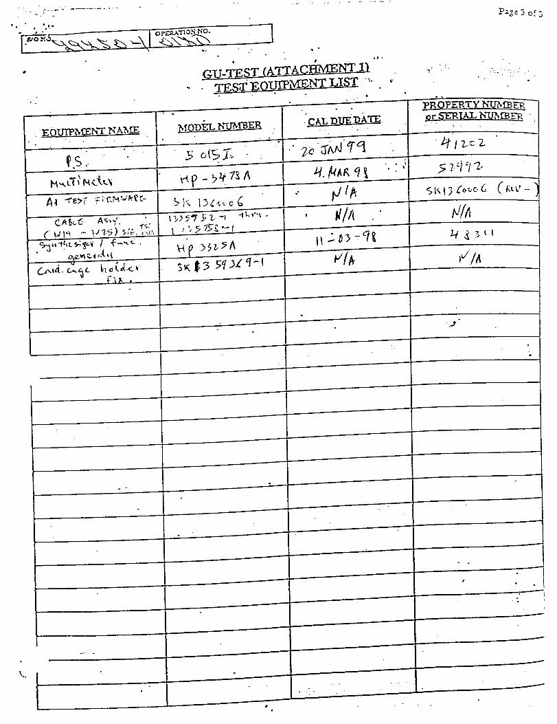
_U-:rSST(AT'rACE_S_rr_- :rss__0._-_,'v_L_S_ '-..
_. . ,
° -
I
_C_,T_._T.rE:_• . • °
_._ -Ii________
• °
,/ .
.-----r------
P_,g-" 3 of 3
._ .
..
I
)Vl_
°
_R._R_Q.PE'RTY h'_?,£B_
_ r .5"smT.AZ,h"U_ _',z_

NFSD 89-0 (June 30, 1989) 53-55FORMS
NASAReport Documentation Page
National Aeronautics and
Space Administration
1. Report No. 2. Government Accession No. 3. Recipient's Catalog No.
5. Report Date
4 May 1998
$ Title and Subtitle
Integrated Advanced Microwave Sounding Unit-A(AMSU-A), METSAT A1 Sig Processor, S/N F01
7. Author(s)
A. Nieto
9. Performing Organization Name and Address
Aerojet1100 W. HollyvaleAzusa, CA 91702
12. Sponsoring Agency Name and Address
NASA
Goddard Space Flight Center
Greenbelt, Maryland 20771
6, Performing Organization Code
8, Performing Organization Report No.
11137
10. Work Unit No.
11 Contract or Grant No.
NAS 5-32314
13. Type of Report and Period Covered
Final
14 Sponsonng Agency Code
15. Supplementary Notes
16. ABSTRACT (Maximum 200
words )
This is the METSAT A1 Signal Processor Engineering Test Report, PIN 1331670-2, SIN
F01 for the Integrated Advanced Microwave Sounding Unit-A (AMSU-A).
17. Key Words (Suggested by Author(s))
Microwave System
19. Security Classif. (of this report)
Unclassified
20, Security Ctassif. (of this page)
Unclassified
NASA FORM 1626 OCT 86
NASA FAR SUPPLEMENT
18. Distdbution Statement
Unclassified --- Unlimited
21 No. of pages 22. Price
18-53.303-1626

53-56 FORMS (June 30, 1989) NFSD 89-0
PREPARATION OF THE REPORT DOCUMENTATION PAGE
The last page of a repo, rt facing the third cover, is the Report Documentation Page, RDP. Information presented on this page isused in announcing ana cataloging reports as web as prepadn 9 the cover ane title page. Thus, it is important that the inTormatlonbe correct. Instrucuons for nling m each block of the Term are as fOllOW'S:
Block 1. Rein No. NASA report series number, if
preassigned.
Block 2. Government Accession No. Leave blank.
Block 3. Recipient's Catalo_ No.. Reserved for use by each
report recipient.
Block 4. Title and Subtitle. Typed in caps and lower case with
dash or period separating subtitle from title.
Block 5. Report Date. Approximate month and year the report
will be published.
Block 6. Performing Organization Cede. Leave blank.
Block 7. Authors. Provide full names exactly as they are to
appear on the title page. If applicable, the word editor should
follow a name.
Block 8. Performing Organization Re_No. NASA installation
report control number and, if desired, the non-NASA performing
organization report control number.
Block 9. Performing.. Organization Name and Address. Provide
affiliation (NASA program office, NASA installation, or contractor
name) of authors.
Block 10. Work Unit No. Provide Research and Technology
Objectives and Plants (RTOP) number.
Block 11. Contract or Grant No. Provide when applicable.
Block 12. Sponsoring Agency Name and Address. National
Aeronautics and Space Administration, Washington, D.C. 20546-
0001. If contractor report, add NASA installation or HQ program
office.
Block 13. Type of Report and Period Covered. NASA formal
report series; for Contractor Report also list type (interim, final)
and period covered when applicable.
Block 14. Sponsoring Agency Code. Leave blank.
Block 15. Supplementary Notes. Information not included
elsewhere: affiliation of authors if additional space is required
for Block 9, notice of work sponsored by another agency, monitor
of contract, information about supplements (file, data tapes, etc.)
meeting site and date for presented papers, journal to which an
article has been submitted, note of a report made from a thesis,
appendix by author other than shown in Block 7.
Block 16. Abstract. The abstract should be informative rather
than descriptive and should state the objectives of the
investigation, the methods employed (e.g., simulation,
experiment, or remote sensing), the results obtained, and the
conclusions reached.
Block 17. Key Words. Identifying words or phrases to be used
in cataloging the report.
Block 18. Distribution Statement. Indicate whether report is
available to public or not. If not to be controlled, use
"Unclassified-Unlimited." If controlled availability is required,
list the category approved on the Document Availability
Authorization Form (see NHB 2200.2, Form FF427). Also
specify subject category (see "Table of Contents" in a current
issue of STAR ) in which report is to be distdbuted.
Block 19. Secunb/ Classification (of the report). Self-
explanatory.
Block 20. Security Classification (of this pa.qe). Self-
explanatory.
Block 21. No. of Pages. Count front matter pages beginning with
iii, text pages including internal blank pages, and the RDP, but
not the title page or the back of the title page.
Block 22. Price Code. If Block 18 shows "Unclassified-
Unlimited," provide the NTIS price code (see "NTIS Price
Schedules" in a current issue of STAR) and at the bottom of the
form add either "For sale by the National Technical Information
Service, Springfield, VA 22161-2171" or "For sale by the
Superintendent of Documents, U.S. Government Printing Office,
Washington, D.C. 20402-0001 ," whichever is appropriate.
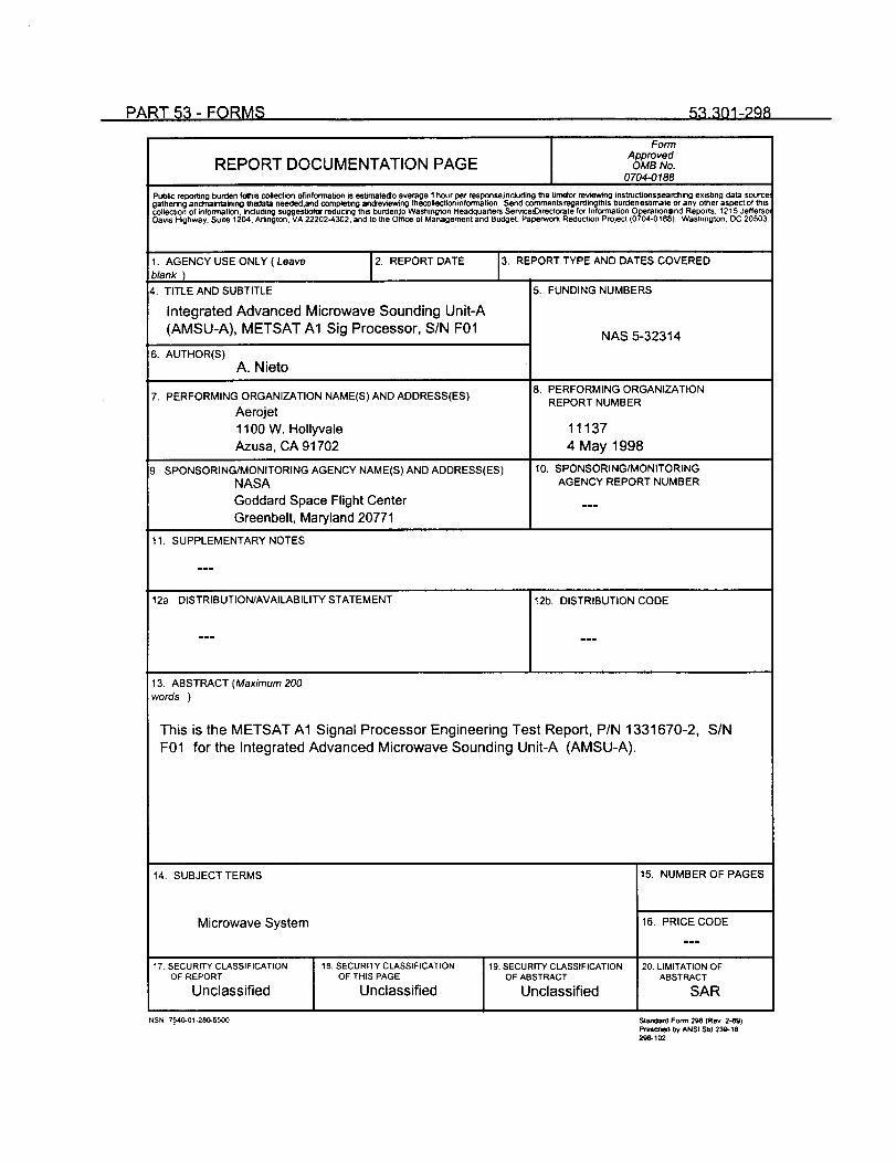
PART _, - FQRM$ 53.301-298
FormApproved
REPORT DOCUMENTATION PAGE OMBNo0704-0188
Public reporting burden fomtlis¢o41ectionofinformabon is estimatedo average I hour per resDonse,thdudthg the bmefor reviewing thstructionssearching exisbng data sourcegathering andmaintaini_g thedata needed,and complebng andreviewtng thecollect_ninfotmaUon. Send commentsregardingthis burdenestimate Or any other aspect of thiscollection of information, including suggestJof_"reducing this burdenlo Washington Headquarters Serviced)irectorate fOr Info_m_tionOperation=nd Repot,s. 121,5 JeffersoDavis Highway. Suite 1204. Artington.VA 22202-4302. and to the Office of Management and Budget. Papefwom Reduction Pro)eel (0704-0188) Washington, DC 20503
1. AGENCY USE ONLY ( Leave
blank )
2. REPORT DATE
4. TITLE AND SUBTITLE
Integrated Advanced Microwave Sounding Unit-A
(AMSU-A), METSAT A1 Sig Processor, SIN F01
6. AUTHOR(S)
A. Nieto
7. PERFORMING ORGANIZATION NAME(S) AND ADDRESS(ES)
Aerojet
1100 W. HollyvaleAzusa, CA 91702
9. SPONSORING/MONITORING AGENCY NAME(S) AND ADDRESS(ES)
NASA
Goddard Space Flight Center
Greenbelt, Maryland 20771
3. REPORT TYPE AND DATES COVERED
5. FUNDING NUMBERS
NAS 5-32314
8. PERFORMING ORGANIZATION
REPORT NUMBER
11137
4 May 1998
10, SPONSORING/MONITORING
AGENCY REPORT NUMBER
11. SUPPLEMENTARY NOTES
12a. DISTRIBUTION/AVAILABILITY STATEMENT 12b. DISTRIBUTION CODE
13. ABSTRACT (Maximum 200
words )
This is the METSAT A1 Signal Processor Engineering Test Report, P/N 1331670-2, S/N
F01 for the Integrated Advanced Microwave Sounding Unit-A (AMSU-A).
14. SUBJECTTERMS
Microwave System
17, SECURITY CLASSIFICATIONOF REPORT
Unclassified
NSN 7540-01-280-5500
18, SECURITY CLASSIFICATIONOF THIS PAGE
Unclassified
19. SECURITY CLASSIFICATIONOF ABSTRACT
Unclassified
15. NUMBER OFPAGES
16. PRICE CODE
mme
20. LIMITATION OFABSTRACT
SAR
Standai_ Form21_ (Rev. 2-89)PrescltedbyANSI ,std 239-18296-102
g3-391-296 FEDERAL ACQUISITION REGULATION (FAR)
GENERAL INSTRUCTIONS FOR COMPLETING SF 298
The Report Documentation Page (RDP) is usecl, in announcing and cataloging reports: It is im_,.rtant that. th!s info.rm.ation be.cq,nsistent with the rest of the report .particulany the cover and title page. inslructions 1or filing in each DlocK of me _ormrollow. It is important to stay within the lines to meet optical scanning r_luirements.
Block 1. Agency Use Only(Leave b/ank_
Block 2. Report Date Full publication date including day,
month, andyear, ff available (e.g., 1 Jan 88). Must cite at least
the year.
Block 3. Type of Report and Dates Covered Statewhetherreport is intedm, final, etc. If applicable, enter inclusive report
dates (e.g., 10 Jun 87 - 30 Jun 88).
Block 4. Title and Subtitle A title is takenfrom the part of the
report that provides the most meaningful and complete
information. When a report il_reparad in more than one volume
report the primary title, add volume number,and include subtitle
for the specific volume. On classified documentsenter the title
classification in parentheses.
Block 5. Funding Numbers To include contract and grant
numbers; may include program element number(s), project
number(s), tasksnumber(s), andwork unit number(s). Use the
following labels:
C Contract PR ProjectG Grant TA Task
PE Program WU Work UnitElement Accession No.
Block 6. Name(s) of person(s) responsible for
writing the report, performingthe research, or credited with thecontent of the'eport. If editoror compiler, this shouldfollow the
name(s).
Block 7. Performing Or,qanization Name(s) and Address(es).
Self-explanatory.
Block 8. Performing Or qanizationReport Number. Enter the
unique alphanumeric report number(s) assigned by the
organization performing the report.
Block 9. Sponsodng/Monitodng Agency Name(s) and
Address(es) Self-explanatory.
Block 10. Sponsoring/Monitodno_AgencyReports Numbe_ (ffknown).
Block 11. SupplementarTNotes. Enter informationnot included
elsewhere such as: Prepared in cooperation with ...; Trans. of...; To be published in ... When a report is revised, include a
statementwhether the new report supersedes or supplements
the older report.
Block 12.a Distribution/Availability StatementDenotes public
availability or limitations. Cite any availability to the public.
Enter additional limitations or special markings in all capitals
(e.g., NOFORN, REL, ITAR).
DOD - See DoDD 5230.24Distribution Statement on
Technical Documents
DOE See authorities.
NASA - See Handbook NHB 2200.2.
NTIS - Leave blank.
Block 12.b Distribution Code.
DOD - Leave blank.
DOE - Enter DOE distribution categories from the
standard Distribution for Unclassified
Scientific and Technical Reports.
NASA - Leave blank.
NTIS - Leave blank.
Block 13. Abstract. Include a bdefMaximum 200 worc_
factual summary of the most significant information contained in
the report.
Block 14. Subject Terms. Keywords or phases identifying major
subjects in the report.
Block 15. Number of Pages.Enter the total number of pages.
Block 16. Pdce Code. Enter appropriate price codel_TIS
only).
Block 17- 19.Security Classifications. Self-explanatory. Enter
U.S. Security Classification in accordance with US. Secudty
Regulations (i.e., UNCLASSIFIED). If form contains classified
information, stamp classification on the top and bottom of the
page.
Block 20. Limitation of Abstract.This block must be completed
to assign a limitation to the abstract. Enter either UL (unlimited)
or SAR (same as report). An entry in this block is necessary if
the abstract is to be limited. If blank, the abstract is assumed to
be unlimited.
Standard Form 298 Back (Rev. 2-89)
53-86