replacement parts for: sprayer - sma · selecting the right pump | replacement parts for sprayer...
TRANSCRIPT

Replacement Parts for:
Sprayer
© 2014 Woods Equipment Company/TISCO All rights reserved. tiscoparts.com • TEL: 800-338-0145 • FAX: 800-356-5487
tiscoparts.com • TEL: 800-338-0145 • FAX: 800-356-5487 © 2014 Woods Equipment Company/TISCO All rights reserved.
Rep
lace
men
t P
arts
for
Sp
raye
r |
Tab
le o
f C
onte
nts
| 2
Pumps ........................................................................................ 3-19 Selecting the Right Pump ...................................................................................3-11
Determining Pump Flow and Pressure Requirements ........................... 6-8
Recommended Pump Placement ................................................................ 9
Sprayer Calibration .....................................................................................10
System Hook-Ups: Centrifugal Pumps ......................................................11
Centrifugal Pumps ........................................................................................... 12-13
Transfer Pumps ......................................................................................................14
Roller Pumps .................................................................................................... 15-16
Roller Pump Kits & Accessories ........................................................................... 17
SHURFLO® Diaphragm Pumps ........................................................................... 18
SHURFLO® Mini-Bulk Chemical Transfer Systems .............................................19
Valves and Couplers ............................................................... 20-21 Couplers ................................................................................................................ 20
Ball Valves .............................................................................................................. 21
Fittings ..................................................................................... 22-23
Gauges .......................................................................................... 24
Hose .............................................................................................. 25
Tips and Nozzles ..................................................................... 26-45 Selecting the Right Spray Tip .......................................................................... 27-30
Spray Tip Selection Guide ......................................................................... 29
Wear and Chemical Compatibility ............................................................ 30
Spraying Systems Cross Reference ............................................................... 31-34
Tips, Nozzles, Fast Caps, Replacement Strainers .......................................... 35-43
Nozzle Bodies and Fittings ................................................................................... 44
Tip Strainers .......................................................................................................... 45
Spray Guns ................................................................................... 46
Spot Sprayers .............................................................................. 47 Backpack Sprayer Gun Parts ................................................................................ 48
3 | Selectin
g th
e Rig
ht P
um
p |
Rep
lacemen
t Parts for Sp
rayer
© 2014 Woods Equipment Company/TISCO All rights reserved. tiscoparts.com • TEL: 800-338-0145 • FAX: 800-356-5487
Selecting the Right Pump
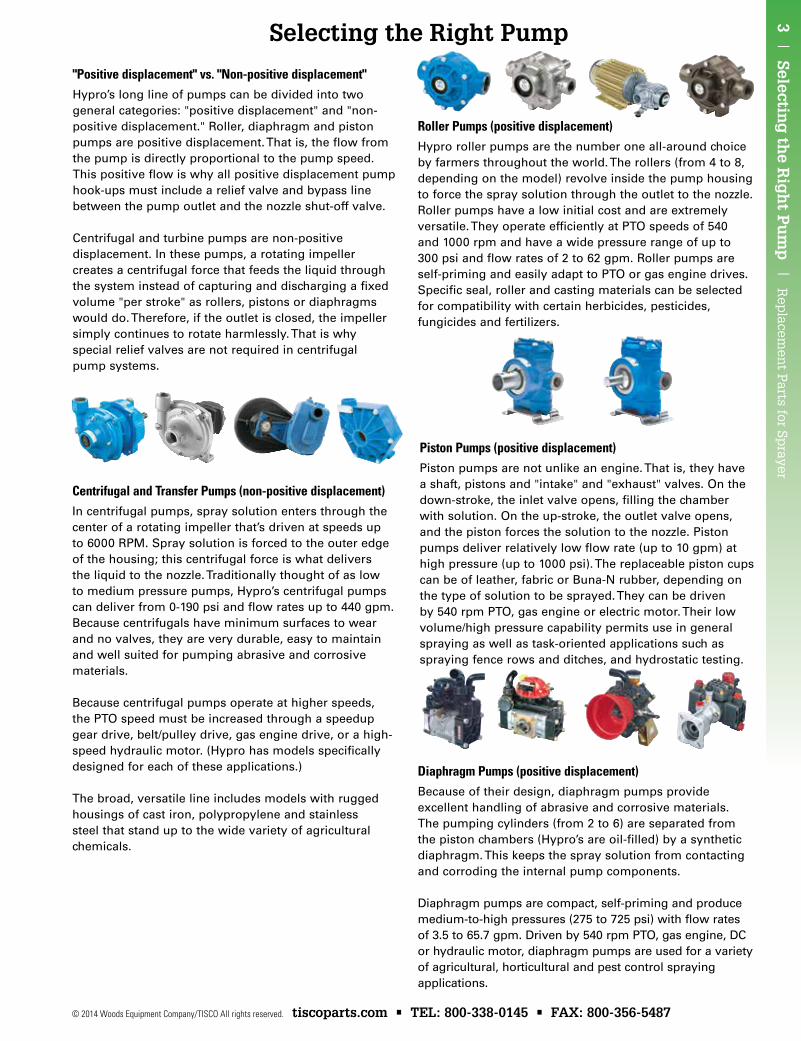
"Positive displacement" vs. "Non-positive displacement"Hypro’s long line of pumps can be divided into two general categories: "positive displacement" and "non-positive displacement." Roller, diaphragm and piston pumps are positive displacement. That is, the flow from the pump is directly proportional to the pump speed. This positive flow is why all positive displacement pump hook-ups must include a relief valve and bypass line between the pump outlet and the nozzle shut-off valve.
Centrifugal and turbine pumps are non-positive displacement. In these pumps, a rotating impeller creates a centrifugal force that feeds the liquid through the system instead of capturing and discharging a fixed volume "per stroke" as rollers, pistons or diaphragms would do. Therefore, if the outlet is closed, the impeller simply continues to rotate harmlessly. That is why special relief valves are not required in centrifugal pump systems.
Centrifugal and Transfer Pumps (non-positive displacement)In centrifugal pumps, spray solution enters through the center of a rotating impeller that’s driven at speeds up to 6000 RPM. Spray solution is forced to the outer edge of the housing; this centrifugal force is what delivers the liquid to the nozzle. Traditionally thought of as low to medium pressure pumps, Hypro’s centrifugal pumps can deliver from 0-190 psi and flow rates up to 440 gpm. Because centrifugals have minimum surfaces to wear and no valves, they are very durable, easy to maintain and well suited for pumping abrasive and corrosive materials.
Because centrifugal pumps operate at higher speeds, the PTO speed must be increased through a speedup gear drive, belt/pulley drive, gas engine drive, or a high-speed hydraulic motor. (Hypro has models specifically designed for each of these applications.)
The broad, versatile line includes models with rugged housings of cast iron, polypropylene and stainless steel that stand up to the wide variety of agricultural chemicals.
Roller Pumps (positive displacement)Hypro roller pumps are the number one all-around choice by farmers throughout the world. The rollers (from 4 to 8, depending on the model) revolve inside the pump housing to force the spray solution through the outlet to the nozzle. Roller pumps have a low initial cost and are extremely versatile. They operate efficiently at PTO speeds of 540 and 1000 rpm and have a wide pressure range of up to 300 psi and flow rates of 2 to 62 gpm. Roller pumps are self-priming and easily adapt to PTO or gas engine drives. Specific seal, roller and casting materials can be selected for compatibility with certain herbicides, pesticides, fungicides and fertilizers.
Diaphragm Pumps (positive displacement)Because of their design, diaphragm pumps provide excellent handling of abrasive and corrosive materials. The pumping cylinders (from 2 to 6) are separated from the piston chambers (Hypro’s are oil-filled) by a synthetic diaphragm. This keeps the spray solution from contacting and corroding the internal pump components.
Diaphragm pumps are compact, self-priming and produce medium-to-high pressures (275 to 725 psi) with flow rates of 3.5 to 65.7 gpm. Driven by 540 rpm PTO, gas engine, DC or hydraulic motor, diaphragm pumps are used for a variety of agricultural, horticultural and pest control spraying applications.
Piston Pumps (positive displacement)Piston pumps are not unlike an engine. That is, they have a shaft, pistons and "intake" and "exhaust" valves. On the down-stroke, the inlet valve opens, filling the chamber with solution. On the up-stroke, the outlet valve opens, and the piston forces the solution to the nozzle. Piston pumps deliver relatively low flow rate (up to 10 gpm) at high pressure (up to 1000 psi). The replaceable piston cups can be of leather, fabric or Buna-N rubber, depending on the type of solution to be sprayed. They can be driven by 540 rpm PTO, gas engine or electric motor. Their low volume/high pressure capability permits use in general spraying as well as task-oriented applications such as spraying fence rows and ditches, and hydrostatic testing.
Rep
lace
men
t P
arts
for
Sp
raye
r |
Sel
ecti
ng
th
e R
igh
t P
um
p |
4
tiscoparts.com • TEL: 800-338-0145 • FAX: 800-356-5487 © 2014 Woods Equipment Company/TISCO All rights reserved.
Selecting the Right Pump
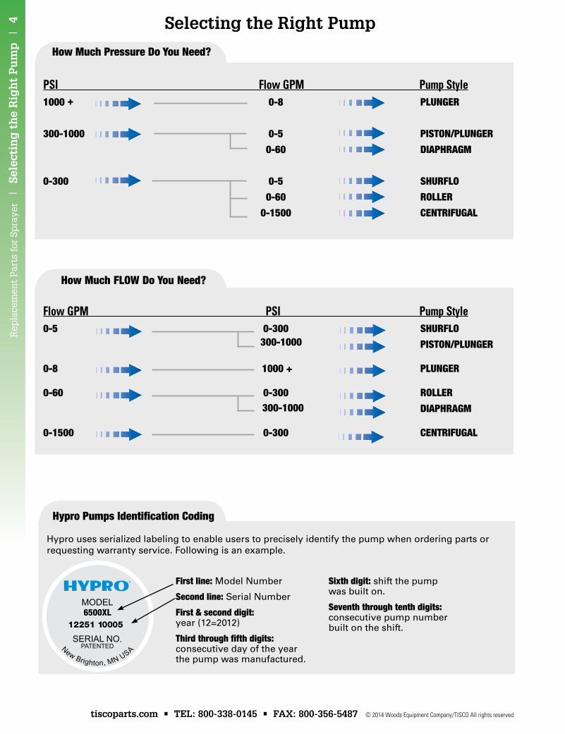
First line: Model Number
Second line: Serial Number
First & second digit: year (12=2012)
Third through fifth digits: consecutive day of the year the pump was manufactured.
Sixth digit: shift the pump was built on.
Seventh through tenth digits: consecutive pump number built on the shift.
PSI Flow GPM Pump Style1000 + 0-8 Plunger
300-1000 0-5 PiSTon/Plunger
0-60 DiaPhragm
0-300 0-5 ShurFlo
0-60 roller
0-1500 CenTriFugal
Flow GPM PSI Pump Style0-5 0-300 ShurFlo
PiSTon/Plunger
0-8 1000 + Plunger
0-60 0-300 roller
DiaPhragm
0-1500 0-300 CenTriFugal
how much Pressure Do You need?
how much FloW Do You need?
300-1000
300-1000
hypro Pumps identification Coding
Hypro uses serialized labeling to enable users to precisely identify the pump when ordering parts or requesting warranty service. Following is an example.
5 | Selectin
g th
e Rig
ht P
um
p |
Rep
lacemen
t Parts for Sp
rayer
© 2014 Woods Equipment Company/TISCO All rights reserved. tiscoparts.com • TEL: 800-338-0145 • FAX: 800-356-5487
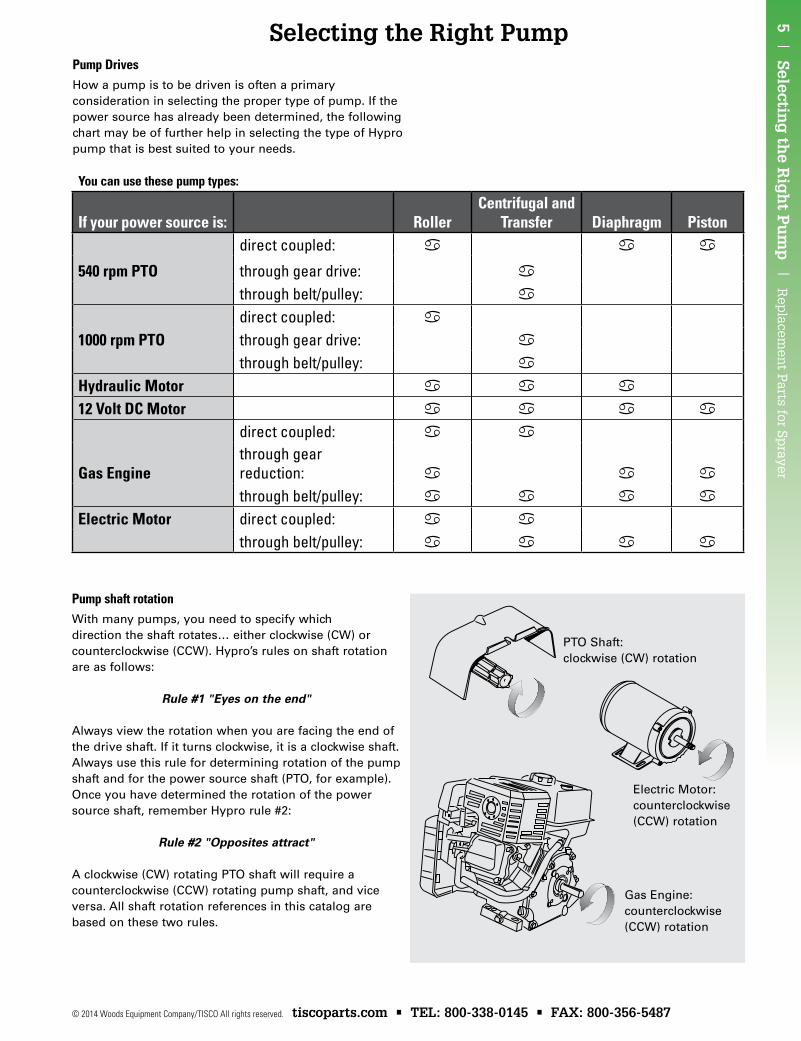
Selecting the Right PumpPump DrivesHow a pump is to be driven is often a primary consideration in selecting the proper type of pump. If the power source has already been determined, the following chart may be of further help in selecting the type of Hypro pump that is best suited to your needs.
PTO Shaft: clockwise (CW) rotation
Electric Motor: counterclockwise (CCW) rotation
Gas Engine: counterclockwise (CCW) rotation
You can use these pump types:
If your power source is: RollerCentrifugal and
Transfer Diaphragm Pistondirect coupled: a a a
540 rpm PTO through gear drive: a
through belt/pulley: a
direct coupled: a
1000 rpm PTO through gear drive: a
through belt/pulley: a
Hydraulic Motor a a a
12 Volt DC Motor a a a a
direct coupled: a a
Gas Enginethrough gear reduction: a a a
through belt/pulley: a a a a
Electric Motor direct coupled: a a
through belt/pulley: a a a a
Pump shaft rotationWith many pumps, you need to specify which direction the shaft rotates… either clockwise (CW) or counterclockwise (CCW). Hypro’s rules on shaft rotation are as follows:
Rule #1 "Eyes on the end"
Always view the rotation when you are facing the end of the drive shaft. If it turns clockwise, it is a clockwise shaft. Always use this rule for determining rotation of the pump shaft and for the power source shaft (PTO, for example). Once you have determined the rotation of the power source shaft, remember Hypro rule #2:
Rule #2 "Opposites attract"
A clockwise (CW) rotating PTO shaft will require a counterclockwise (CCW) rotating pump shaft, and vice versa. All shaft rotation references in this catalog are based on these two rules.
Rep
lace
men
t P
arts
for
Sp
raye
r |
Sel
ecti
ng
th
e R
igh
t P
um
p |
6
tiscoparts.com • TEL: 800-338-0145 • FAX: 800-356-5487 © 2014 Woods Equipment Company/TISCO All rights reserved.
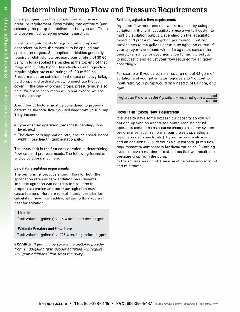
Determining Pump Flow and Pressure RequirementsEvery pumping task has an optimum volume and pressure requirement. Determining that optimum (and selecting the pump that delivers it) is key to an efficient and economical spraying system operation.
Pressure requirements for agricultural pumps are dependent on both the material to be applied and application targets. Soil-applied herbicides generally require a relatively low pressure pump rating of 30-60 psi with foliar-applied herbicides at the top end of that range and slightly higher. Insecticides and fungicides require higher pressure ratings of 100 to 500 psi. Pressure must be sufficient, in the case of heavy foliage field crops and orchard crops, to penetrate the leaf cover. In the case of orchard crops, pressure must also be sufficient to carry material up and over as well as into the canopy.
A number of factors must be considered to properly determine the total flow you will need from your pump. They include:
• Type of spray operation (broadcast, banding, low- level, etc.)
• The chemical’s application rate, ground speed, boom width, hose length, tank agitation, etc.
The spray task is the first consideration in determining flow rate and pressure needs. The following formulas and calculations may help.
Calculating agitation requirementsThe pump must produce enough flow for both the application rate and tank agitation requirements. Too little agitation will not keep the solution in proper suspension and too much agitation may cause foaming. Here are rule of thumb formulas for calculating how much additional pump flow you will needfor agitation.
Liquids: Tank volume (gallons) x .05 = total agitation in gpm
Wettable Powders and Flowables: Tank volume (gallons) x .125 = total agitation in gpm
EXAMPLE: If you will be spraying a wettable powder from a 100-gallon tank, proper agitation will require 12.5 gpm additional flow from the pump.
Reducing agitation flow requirementsAgitation flow requirements can be reduced by using jet agitation in the tank. Jet agitators use a venturi design to multiply agitation output. Depending on the jet agitator model and pressure, one gallon per minute input can provide two to ten gallons per minute agitation output. If your sprayer is equipped with a jet agitator, consult the operator’s manual or documentation to find the output to input ratio and adjust your flow required for agitation accordingly.
For example: If you calculate a requirement of 63 gpm of agitation and your jet agitator requires 3 to 1 output to input ratio, your pump would only need 1⁄3 of 63 gpm, or 21 gpm.
Agitation Flow with Jet Agitation = required gpm x input
output
Factor in an "Excess Flow" RequirementIt is wise to have some excess flow capacity so you will not end up with an undersized pump because actual operation conditions may cause changes in spray system performance (such as normal pump wear, operating at less than rated speeds, etc.). Hypro recommends you add an additional 20% to your calculated total pump flow requirement to compensate for these variables. Plumbing systems have a number of restrictions that will result in a pressure drop from the pump to the actual spray point. These must be taken into account and minimized.

7 | Selectin
g th
e Rig
ht P
um
p |
Rep
lacemen
t Parts for Sp
rayer
© 2014 Woods Equipment Company/TISCO All rights reserved. tiscoparts.com • TEL: 800-338-0145 • FAX: 800-356-5487
Determining Pump Flow and Pressure Requirements
For total pump flow requirement (banding), calculate:
Flow required for boom: _____ gpmFlow required for agitation: + ______ gpmSub-total = ______ gpmExcess flow requirement: x ______TOTAL PUMP FLOW NEEDED: = ______ gpm
Calculating pump flow for hand gun sprayingFor low-level spraying with a hand gun, such as for lawn and turf care, professional applicators typically "walk" the lawn at about 1,000 sq. ft. per minute. That means the "gpm" rate of the hand gun will generally be the same as "gallons per 1,000 sq. ft." To determine your total pump flow requirement:
Flow required for gun/nozzle: _______ gallons per 1,000ft2 (same as gpm)Flow required for agitation: + ______ gpmSub-total = ______ gpmExcess flow requirement: x ______ TOTAL PUMP FLOW NEEDED: = ______ gpm
Use this same method for calculating the pump flow requirement for high pressure spraying, such as trees. Even though the application "rate" is usually a visual saturation of the tree, the known gpm factor will be the hand gun nozzle output, which is the rate you use for the calculation.
1.20
Calculating pump flow for broadcast boom sprayersChemical application is measured in gallons per acre (gpa), whereas pump flow is stated in gallons per minute (gpm). To calculate the pump flow gpm required by a broadcast boom sprayer, multiply the gpa application rate (from the chemical label, usually 10-20 gpa) by the sprayer ground speed (5-10 mph). Multiply the sum by the boom width on your sprayer (in feet). Then, divide that number by 495. As a formula, it is written like this:
Flow required for boom (gpm) = gpa x mph x boom width (ft.) 495
The result will be the pump flow required to deliver the proper application rate at the boom’s nozzles. Then calculate your total pump flow requirement (broadcast):
Flow required for boom: _______ gpmFlow required for agitation: + ________ gpmSub-total = ________ gpmExcess flow requirement: x ________TOTAL PUMP FLOW NEEDED: = ________ gpm
1.20
Calculating pump flow for banding sprayersFirst, multiply the band width (in inches) by the number of rows to determine the total width (w). Then, multiply the application rate (gpa from the chemical label) by the ground speed (mph). Multiply that result by the total width (w) calculated earlier, then divide the result by 5940. Here’s how the formula appears:
Flow required for nozzles (gpm) = gpa x mph x w 5940
1.20
Rep
lace
men
t P
arts
for
Sp
raye
r |
Sel
ecti
ng
th
e R
igh
t P
um
p |
8
tiscoparts.com • TEL: 800-338-0145 • FAX: 800-356-5487 © 2014 Woods Equipment Company/TISCO All rights reserved.
Determining Pump Flow and Pressure Requirements
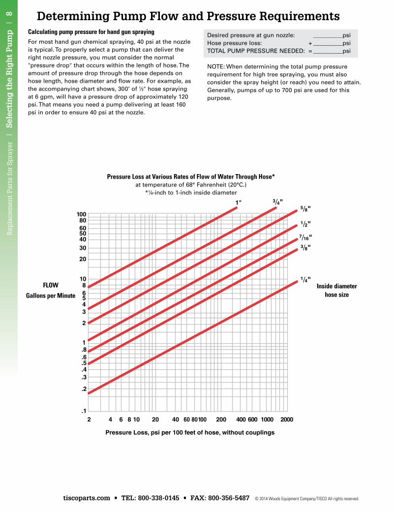
Pressure Loss at Various Rates of Flow of Water Through Hose*at temperature of 68° Fahrenheit (20°C.)
*1⁄4-inch to 1-inch inside diameter
Calculating pump pressure for hand gun sprayingFor most hand gun chemical spraying, 40 psi at the nozzle is typical. To properly select a pump that can deliver the right nozzle pressure, you must consider the normal "pressure drop" that occurs within the length of hose. The amount of pressure drop through the hose depends on hose length, hose diameter and flow rate. For example, as the accompanying chart shows, 300’ of 1⁄2" hose spraying at 6 gpm, will have a pressure drop of approximately 120 psi. That means you need a pump delivering at least 160 psi in order to ensure 40 psi at the nozzle.
Desired pressure at gun nozzle: __________psiHose pressure loss: + __________psiTOTAL PUMP PRESSURE NEEDED: = __________psi
NOTE: When determining the total pump pressure requirement for high tree spraying, you must also consider the spray height (or reach) you need to attain. Generally, pumps of up to 700 psi are used for this purpose.
FLOW
Gallons per MinuteInside diameter
hose size
9 | Selectin
g th
e Rig
ht P
um
p |
Rep
lacemen
t Parts for Sp
rayer
© 2014 Woods Equipment Company/TISCO All rights reserved. tiscoparts.com • TEL: 800-338-0145 • FAX: 800-356-5487
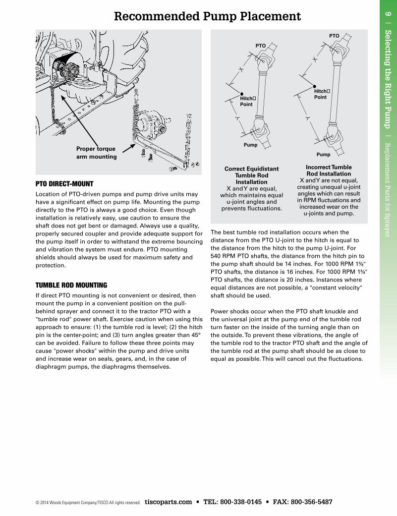
Recommended Pump Placement
PTo DireCT-mounTLocation of PTO-driven pumps and pump drive units may have a significant effect on pump life. Mounting the pump directly to the PTO is always a good choice. Even though installation is relatively easy, use caution to ensure the shaft does not get bent or damaged. Always use a quality, properly secured coupler and provide adequate support for the pump itself in order to withstand the extreme bouncing and vibration the system must endure. PTO mounting shields should always be used for maximum safety and protection.
Tumble roD mounTingIf direct PTO mounting is not convenient or desired, then mount the pump in a convenient position on the pull-behind sprayer and connect it to the tractor PTO with a "tumble rod" power shaft. Exercise caution when using this approach to ensure: (1) the tumble rod is level; (2) the hitch pin is the center-point; and (3) turn angles greater than 45° can be avoided. Failure to follow these three points may cause "power shocks" within the pump and drive units and increase wear on seals, gears, and, in the case of diaphragm pumps, the diaphragms themselves.
The best tumble rod installation occurs when the distance from the PTO U-joint to the hitch is equal to the distance from the hitch to the pump U-joint. For 540 RPM PTO shafts, the distance from the hitch pin to the pump shaft should be 14 inches. For 1000 RPM 13⁄8" PTO shafts, the distance is 16 inches. For 1000 RPM 13⁄4" PTO shafts, the distance is 20 inches. Instances where equal distances are not possible, a "constant velocity" shaft should be used.
Power shocks occur when the PTO shaft knuckle and the universal joint at the pump end of the tumble rod turn faster on the inside of the turning angle than on the outside. To prevent these vibrations, the angle of the tumble rod to the tractor PTO shaft and the angle of the tumble rod at the pump shaft should be as close to equal as possible. This will cancel out the fluctuations.
Proper torque arm mounting
PTO PTO
Hitch�Point Hitch�
Point
Pump
Pump
Incorrect TumbleRod Installation
X and Y are not equal, creating unequal u-joint angles which can result in RPM fluctuations and increased wear on the
u-joints and pump.
Correct EquidistantTumble Rod Installation
X and Y are equal, which maintains equal
u-joint angles and prevents fluctuations.
PTO PTO
Hitch�Point Hitch�
Point
Pump
Pump

Rep
lace
men
t P
arts
for
Sp
raye
r |
Sel
ecti
ng
th
e R
igh
t P
um
p |
10
tiscoparts.com • TEL: 800-338-0145 • FAX: 800-356-5487 © 2014 Woods Equipment Company/TISCO All rights reserved.
Width of Spray Pattern in Directed Applications = band width
# of nozzles per band
Sprayer Calibration3. Multiply the application rate (gpa) by the speed (mph) and the width of the spray pattern (w)*. Divide this amount by 5940 (a constant) to determine the gallons per minute (gpm) produced by each nozzle.
Flow required per nozzle (gpm) = gpa x mph x w 5940
4. To set correct pressure, operate the water filled sprayer in place to check for leaks and stoppages. Stop the sprayer, and replace one tip on the boom with an identical new tip and strainer. Check the tip product information sheet for recommended delivery rate and pressure that matches the gpm level calculated in Step 3.
Engage the sprayer and adjust for recommended pressure. Collect the volume of spray produced from the new nozzle tip over a one minute period. Measure the water, and fine tune the pressure setting until the calculated delivery rate is reached.
5. Repeat the collection procedure with several tips on each boom section. If variations in flow in excess of 10% are produced from more than one tip, replace all old tips and screens.
*If calibrating a sprayer for broadcast application, use nozzle spacing for spray pattern width. If calibrating for banding, use only actual spray pattern in inches (12 bands of 10" each on 30" rows equals spray pattern width of 120" on a 30' boom).
Directed applications with multiple nozzles require that the row or band in inches be divided by the number of nozzles directed at the row to calculate width.
Improperly calibrated sprayers threaten the wallet and the environment. A few minutes spent calibrating a sprayer can ensure expensive inputs go where they are supposed to and at their recommended rate. Proper calibration exposes under-pressured systems and worn tips that can sabotage a spray program and its budget. Follow these steps to calibrate your sprayer safely and effectively.
1. The first step in any calibration effort is to check tractor speed. Mark off lengths of 100 and 200 ft. for measuring tractor speeds of 5 mph and 10 mph, respectively. Fill the sprayer tank half full of water, select the engine throttle setting and gear that you expect to use when spraying, and then record the seconds required to drive the length of each course twice at their respective settings. Average the results of each set, and use the following equation to determine ground speed.
Repeat the test as needed until the correct speed is identified. Mark that setting on the tachometer or speedometer for infield reference.
2. Record the nozzle spacing, nozzle type, ground speed and product label application rate. Check to ensure all nozzles are of a uniform type.
Speed = Distance (ft.) x 60 Time (sec.) x 88
11 | Selectin
g th
e Rig
ht P
um
p |
Rep
lacemen
t Parts for Sp
rayer
© 2014 Woods Equipment Company/TISCO All rights reserved. tiscoparts.com • TEL: 800-338-0145 • FAX: 800-356-5487
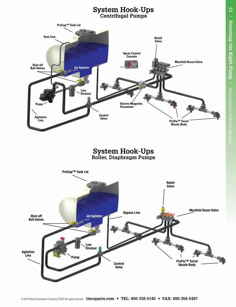
System Hook-UpsCentrifugal Pumps
Shut-offBall Valves
AgitationLine
Pump
ReliefValve
Manifold Boom Valve
Electro-MagneticFlowmeter
ProFlo™ TurretNozzle Body
Spray ControlConsole
ControlValve
ProCap™ Tank Lid
Jet Agitator
Vent Line
LineStrainer
Shut-offBall Valves
AgitationLine Pump
ReliefValve
Manifold Boom Valve
ProFlo™ TurretNozzle BodyControl
Valve
ProCap™ Tank Lid
Jet AgitatorBypass Line
LineStrainer
System Hook-UpsRoller, Diaphragm Pumps
Rep
lace
men
t P
arts
for
Sp
raye
r |
Cen
trif
ug
al P
um
ps
| 1
2
tiscoparts.com • TEL: 800-338-0145 • FAX: 800-356-5487 © 2014 Woods Equipment Company/TISCO All rights reserved.
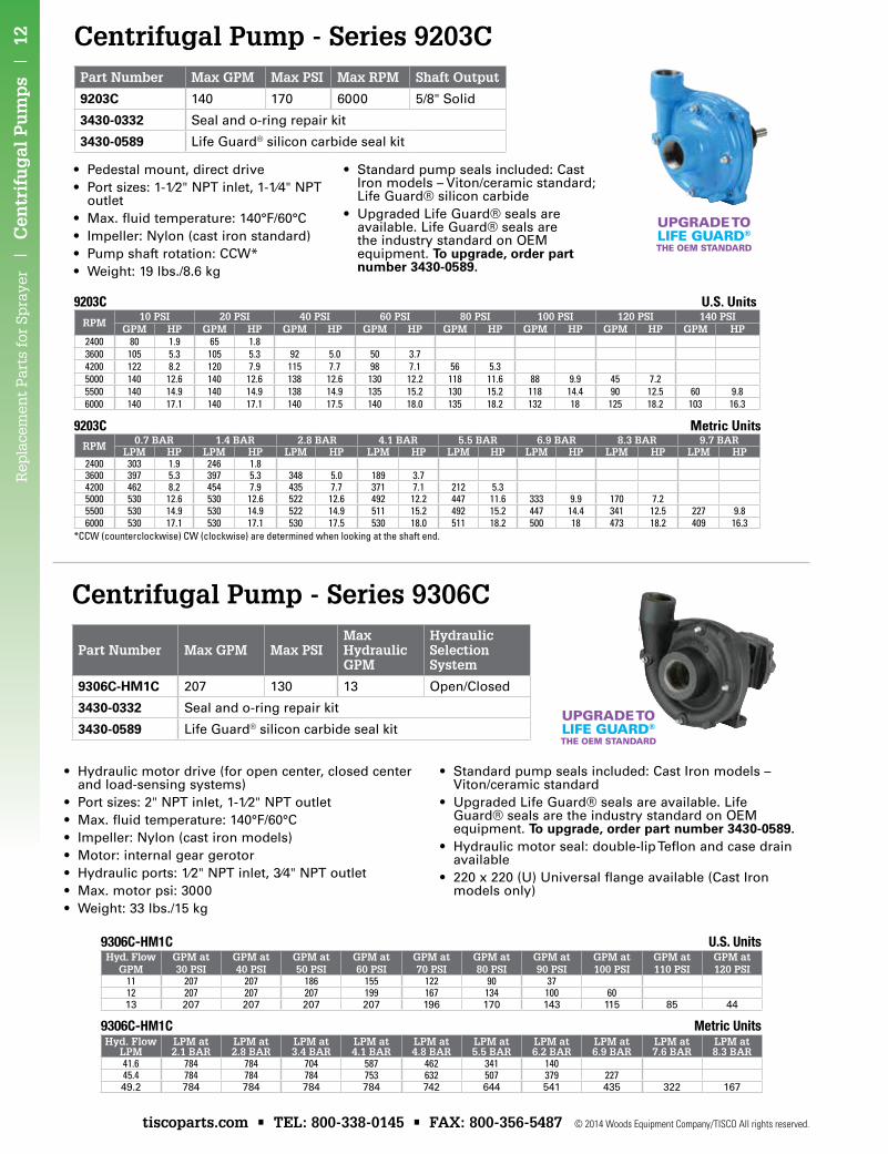
Centrifugal Pump - Series 9203CPart Number Max GPM Max PSI Max RPM Shaft Output
9203C 140 170 6000 5/8" Solid
3430-0332 Seal and o-ring repair kit
3430-0589 Life Guard® silicon carbide seal kit
9203C U.S. UnitsRPM
10 PSI 20 PSI 40 PSI 60 PSI 80 PSI 100 PSI 120 PSI 140 PSIGPM HP GPM HP GPM HP GPM HP GPM HP GPM HP GPM HP GPM HP
2400 80 1.9 65 1.83600 105 5.3 105 5.3 92 5.0 50 3.74200 122 8.2 120 7.9 115 7.7 98 7.1 56 5.35000 140 12.6 140 12.6 138 12.6 130 12.2 118 11.6 88 9.9 45 7.25500 140 14.9 140 14.9 138 14.9 135 15.2 130 15.2 118 14.4 90 12.5 60 9.86000 140 17.1 140 17.1 140 17.5 140 18.0 135 18.2 132 18 125 18.2 103 16.3
9203C Metric UnitsRPM 0.7 BAR 1.4 BAR 2.8 BAR 4.1 BAR 5.5 BAR 6.9 BAR 8.3 BAR 9.7 BAR
LPM HP LPM HP LPM HP LPM HP LPM HP LPM HP LPM HP LPM HP2400 303 1.9 246 1.83600 397 5.3 397 5.3 348 5.0 189 3.74200 462 8.2 454 7.9 435 7.7 371 7.1 212 5.35000 530 12.6 530 12.6 522 12.6 492 12.2 447 11.6 333 9.9 170 7.25500 530 14.9 530 14.9 522 14.9 511 15.2 492 15.2 447 14.4 341 12.5 227 9.86000 530 17.1 530 17.1 530 17.5 530 18.0 511 18.2 500 18 473 18.2 409 16.3
• Pedestal mount, direct drive• Port sizes: 1-1⁄2" NPT inlet, 1-1⁄4" NPT
outlet• Max. fluid temperature: 140°F/60°C• Impeller: Nylon (cast iron standard)• Pump shaft rotation: CCW*• Weight: 19 lbs./8.6 kg
• Standard pump seals included: Cast Iron models – Viton/ceramic standard; Life Guard® silicon carbide
• Upgraded Life Guard® seals are available. Life Guard® seals are the industry standard on OEM equipment. To upgrade, order part number 3430-0589.
*CCW (counterclockwise) CW (clockwise) are determined when looking at the shaft end.
UPGRADE TOLIFE GUARD®
THE OEM STANDARD
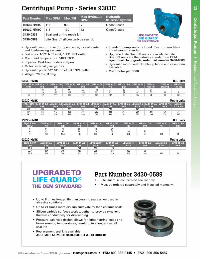
Centrifugal Pump - Series 9306C
9306C-HM1C Metric Units Hyd. Flow
LPMLPM at 2.1 BAR
LPM at 2.8 BAR
LPM at 3.4 BAR
LPM at 4.1 BAR
LPM at 4.8 BAR
LPM at 5.5 BAR
LPM at 6.2 BAR
LPM at 6.9 BAR
LPM at 7.6 BAR
LPM at 8.3 BAR
41.6 784 784 704 587 462 341 14045.4 784 784 784 753 632 507 379 22749.2 784 784 784 784 742 644 541 435 322 167
9306C-HM1C U.S. UnitsHyd. Flow
GPMGPM at 30 PSI
GPM at 40 PSI
GPM at 50 PSI
GPM at 60 PSI
GPM at 70 PSI
GPM at 80 PSI
GPM at 90 PSI
GPM at 100 PSI
GPM at 110 PSI
GPM at 120 PSI
11 207 207 186 155 122 90 3712 207 207 207 199 167 134 100 6013 207 207 207 207 196 170 143 115 85 44
• Hydraulic motor drive (for open center, closed center and load-sensing systems)
• Port sizes: 2" NPT inlet, 1-1⁄2" NPT outlet• Max. fluid temperature: 140°F/60°C• Impeller: Nylon (cast iron models)• Motor: internal gear gerotor• Hydraulic ports: 1⁄2" NPT inlet, 3⁄4" NPT outlet• Max. motor psi: 3000• Weight: 33 lbs./15 kg
• Standard pump seals included: Cast Iron models – Viton/ceramic standard
• Upgraded Life Guard® seals are available. Life Guard® seals are the industry standard on OEM equipment. To upgrade, order part number 3430-0589.
• Hydraulic motor seal: double-lip Teflon and case drain available
• 220 x 220 (U) Universal flange available (Cast Iron models only)
UPGRADE TOLIFE GUARD®
THE OEM STANDARD
Part Number Max GPM Max PSIMax Hydraulic GPM
Hydraulic Selection System
9306C-HM1C 207 130 13 Open/Closed
3430-0332 Seal and o-ring repair kit
3430-0589 Life Guard® silicon carbide seal kit
13 | C
entrifu
gal P
um
ps |
Rep
lacemen
t Parts for Sp
rayer
© 2014 Woods Equipment Company/TISCO All rights reserved. tiscoparts.com • TEL: 800-338-0145 • FAX: 800-356-5487
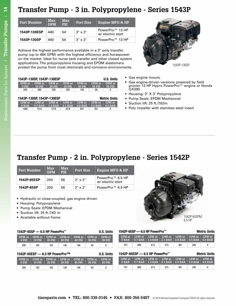
Centrifugal Pump - Series 9303C
Part Number Max GPM Max PSI Max Hydraulic GPM
Hydraulic Selection System
9303C-HM4C 115 93 7 Open/Closed
9303C-HM1C 114 130 13 Open/Closed
3430-0332 Seal and o-ring repair kit
3430-0589 Life Guard® silicon carbide seal kit
• Hydraulic motor drive (for open center, closed center and load-sensing systems)
• Port sizes: 1-1⁄2" NPT inlet, 1-1⁄4" NPT outlet• Max. fluid temperature: 140°F/60°C• Impeller: Cast Iron models – Nylon• Motor: internal gear gerotor• Hydraulic ports: 1⁄2" NPT inlet, 3⁄4" NPT outlet• Weight: 26 lbs./11.8 kg
• Standard pump seals included: Cast Iron models – Viton/ceramic standard
• Upgraded Life Guard® seals are available. Life Guard® seals are the industry standard on OEM equipment. To upgrade, order part number 3430-0589.
• Hydraulic motor seal: double-lip Teflon and case drain available
• Max. motor psi: 3000
9303C-HM4C Metric UnitsHyd. Flow
LPMLPM at 0.7
BARLPM at 1.4
BARLPM at 2.1
BARLPM at 2.8
BARLPM at 3.4
BARLPM at 4.1
BARLPM at 4.8
BARLPM at 5.5
BARLPM at 6.2
BAR18.9 318 288 250 197 12922.7 367 348 326 295 254 189 9526.5 416 394 371 344 310 261 208 144 53
9303C-HM4C U.S. UnitsHyd. Flow
GPMGPM at 10
PSIGPM at 20
PSIGPM at 30
PSIGPM at 40
PSIGPM at 50
PSIGPM at 60
PSIGPM at 70
PSIGPM at 80
PSIGPM at 90
PSI5 84 76 66 52 346 97 92 86 78 67 50 257 110 104 98 91 82 69 55 38 14
9303C-HM1C Metric UnitsHyd. Flow
LPMLPM at 1.4
BARLPM at 2.1
BARLPM at 2.8
BARLPM at 3.4
BARLPM at 4.1
BARLPM at 4.8
BARLPM at 5.5
BARLPM at 6.2
BARLPM at 6.9
BARLPM at 7.6
BARLPM at 8.3 BAR
41.6 394 382 363 341 310 269 227 178 11745.4 416 413 405 397 382 348 307 254 201 136 3449.2 424 420 413 405 394 386 363 322 288 238 125
9303C-HM1C U.S. UnitsHyd. Flow
GPMGPM at 20
PSIGPM at 30
PSIGPM at 40
PSIGPM at 50
PSIGPM at 60
PSIGPM at 70
PSIGPM at 80
PSIGPM at 90
PSIGPM at 100 PSI
GPM at 110 PSI
GPM at 120 PSI
11 104 101 96 90 82 71 60 47 3112 110 109 107 105 101 92 81 67 53 36 913 112 111 109 107 104 102 96 85 76 63 33
UPGRADE TOLIFE GUARD®
THE OEM STANDARD
Part Number 3430-0589• Life Guard silicon carbide seal kit only.
• Must be ordered separately and installed manually.
UPGRADE TOLIFE GUARD®
THE OEM STANDARD
• Up to 8 times longer life than ceramic seals when used in abrasive solutions
• Up to 21 times more dry-run survivability than ceramic seals
• Silicon carbide surfaces work together to provide excellent thermal conductivity for dry-running
• Pressure-balanced design allows for lighter spring loads and lower running temperatures, resulting in a longer overall seal life
• Replacement seal kits available. ADD PART NuMbER 3430-0589 To youR oRDER!
Rep
lace
men
t P
arts
for
Sp
raye
r |
Tra
nsf
er P
um
ps
| 1
4
tiscoparts.com • TEL: 800-338-0145 • FAX: 800-356-5487 © 2014 Woods Equipment Company/TISCO All rights reserved.
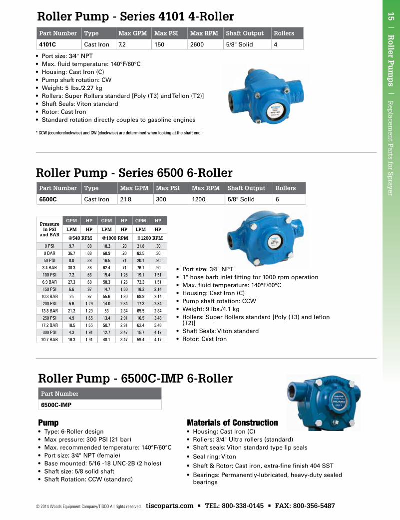
Transfer Pump - 3 in. Polypropylene - Series 1543P
Transfer Pump - 2 in. Polypropylene - Series 1542P
Part Number Max GPM
Max PSI Port Size Engine MFG & HP
1543P-130ESP 440 54 3" x 3" PowerPro™ 13 HP w/ electric start
1543P-130SP 440 54 3" x 3" PowerPro™ 13 HP
1543P-130SP
Achieve the highest performance available in a 3" poly transfer pump (up to 484 GPM) with the highest efficiency and horsepower on the market. Ideal for nurse tank transfer and other closed system applications. The polypropylene housing and EPDM elastomers protect the pump from most chemicals and corrosive environments.
• Gas engine mount,• Gas engine-driven versions powered by field
proven 13 HP Hypro PowerPro™ engine or Honda GX390
• Housing: 3" X 3" Polypropylene• Pump Seals: EPDM Mechancial• Suction lift: 25 ft./7.62m• Poly impeller with stainless steel insert
1543P-130SP, 1543P-130ESP Metric UnitsLPM at 0 BAR
LPM at 0.7 BAR
LPM at 1.4 BAR
LPM at 2.1 BAR
LPM at 2.8 BAR
LPM at 3.4 BAR
LPM at 4.0 BAR
1666 1514 1279 1018 697 257 0
1543P-130SP, 1543P-130ESP U.S. UnitsGPM at
0 PSIGPM at 10 PSI
GPM at 20 PSI
GPM at 30 PSI
GPM at 40 PSI
GPM at 50 PSI
GPM at 58 PSI
440 400 338 269 184 68 0
• Hydraulic or close-coupled, gas engine driven• Housing: Polypropylene• Pump Seals: EPDM Mechanical• Suction lift: 25 ft./7.62 m• Available without frame 1542P-65SPM
6.5 HP
1542P-65SP — 6.5 HP PowerPro™ Metric UnitsLPM at 0 BAR
LPM at 0.7 BAR
LPM at 1.4 BAR
LPM at 2.1 BAR
LPM at 2.8 BAR
LPM at 3.4 BAR
LPM at 4.0 BAR
757 689 613 515 401 246 0
1542P-65ESP — 6.5 HP PowerPro™ Metric UnitsLPM at 0 BAR
LPM at 0.7 BAR
LPM at 1.4 BAR
LPM at 2.1 BAR
LPM at 2.8 BAR
LPM at 3.4 BAR
LPM at 4.0 BAR
757 689 613 515 401 246 0
1542P-65SP — 6.5 HP PowerPro™ U.S. UnitsGPM at
0 PSIGPM at 10 PSI
GPM at 20 PSI
GPM at 30 PSI
GPM at 40 PSI
GPM at 50 PSI
GPM at 58 PSI
200 182 162 136 106 65 0
1542P-65ESP — 6.5 HP PowerPro™ U.S. UnitsGPM at
0 PSIGPM at 10 PSI
GPM at 20 PSI
GPM at 30 PSI
GPM at 40 PSI
GPM at 50 PSI
GPM at 58 PSI
200 182 162 136 106 65 0
Part Number Max GPM
Max PSI Port Size Engine MFG & HP
1542P-65ESP 200 58 2" x 2" PowerPro™ 6.5 HP w/ electric start
1542P-65SP 200 58 2" x 2" PowerPro™ 6.5 HP
Roller Pump - Series 4101 4-Roller
15 | R
oller Pu
mp
s | R
eplacem
ent P
arts for Sprayer
© 2014 Woods Equipment Company/TISCO All rights reserved. tiscoparts.com • TEL: 800-338-0145 • FAX: 800-356-5487
Roller Pump - Series 4101 4-Roller
Roller Pump - Series 6500 6-RollerPart Number Type Max GPM Max PSI Max RPM Shaft Output Rollers
6500C Cast Iron 21.8 300 1200 5/8" Solid 6
• Port size: 3⁄4" NPT• Max. fluid temperature: 140°F/60°C• Housing: Cast Iron (C)• Pump shaft rotation: CW• Weight: 5 lbs./2.27 kg• Rollers: Super Rollers standard [Poly (T3) and Teflon (T2)]• Shaft Seals: Viton standard• Rotor: Cast Iron• Standard rotation directly couples to gasoline engines
* CCW (counterclockwise) and CW (clockwise) are determined when looking at the shaft end.
Part Number Type Max GPM Max PSI Max RPM Shaft Output Rollers
4101C Cast Iron 7.2 150 2600 5/8" Solid 4
• Port size: 3⁄4" NPT• 1" hose barb inlet fitting for 1000 rpm operation• Max. fluid temperature: 140°F/60°C• Housing: Cast Iron (C)• Pump shaft rotation: CCW• Weight: 9 lbs./4.1 kg• Rollers: Super Rollers standard [Poly (T3) and Teflon
(T2)]• Shaft Seals: Viton standard• Rotor: Cast Iron
Roller Pump - 6500C-IMP 6-RollerPart Number
6500C-IMP
Pump• Type: 6-Roller design• Max pressure: 300 PSI (21 bar)• Max. recommended temperature: 140°F/60°C• Port size: 3⁄4" NPT (female)• Base mounted: 5/16 -18 UNC-2B (2 holes)• Shaft size: 5/8 solid shaft• Shaft Rotation: CCW (standard)
materials of Construction• Housing: Cast Iron (C)• Rollers: 3/4" Ultra rollers (standard)• Shaft seals: Viton standard type lip seals
• Seal ring: Viton
• Shaft & Rotor: Cast iron, extra-fine finish 404 SST
• Bearings: Permanently-lubricated, heavy-duty sealed bearings
Pressurein PSI
and BAR
GPM HP GPM HP GPM HP
LPM HP LPM HP LPM HP
@540 RPM @1000 RPM @1200 RPM
0 PSI 9.7 .08 18.2 .20 21.8 .300 BAR 36.7 .08 68.9 .20 82.5 .3050 PSI 8.0 .38 16.5 .71 20.1 .90
3.4 BAR 30.3 .38 62.4 .71 76.1 .90100 PSI 7.2 .68 15.4 1.26 19.1 1.516.9 BAR 27.3 .68 58.3 1.26 72.3 1.51150 PSI 6.6 .97 14.7 1.80 18.2 2.14
10.3 BAR 25 .97 55.6 1.80 68.9 2.14200 PSI 5.6 1.29 14.0 2.34 17.3 2.84
13.8 BAR 21.2 1.29 53 2.34 65.5 2.84250 PSI 4.9 1.65 13.4 2.91 16.5 3.48
17.2 BAR 18.5 1.65 50.7 2.91 62.4 3.48300 PSI 4.3 1.91 12.7 3.47 15.7 4.17
20.7 BAR 16.3 1.91 48.1 3.47 59.4 4.17
Rep
lace
men
t P
arts
for
Sp
raye
r |
Rol
ler
Pu
mp
s |
16
tiscoparts.com • TEL: 800-338-0145 • FAX: 800-356-5487 © 2014 Woods Equipment Company/TISCO All rights reserved.
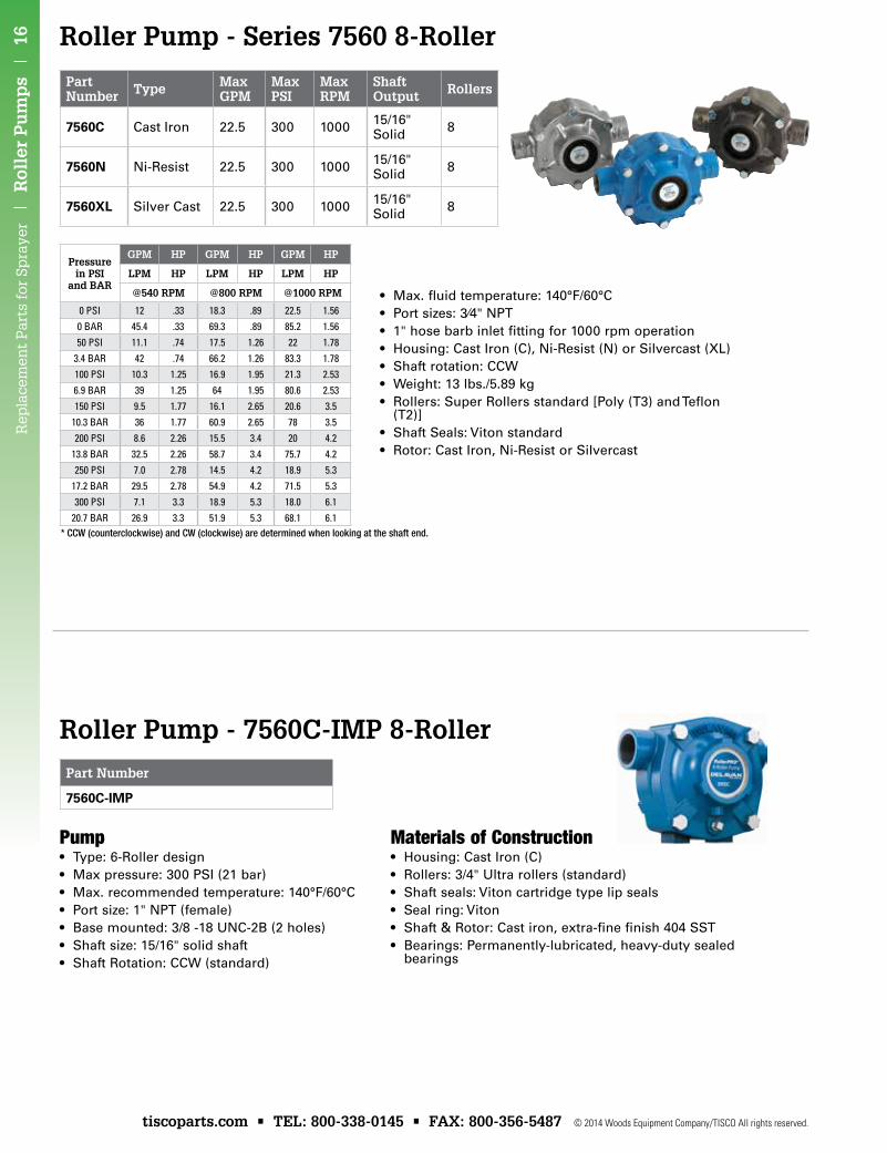
• Max. fluid temperature: 140°F/60°C• Port sizes: 3⁄4" NPT • 1" hose barb inlet fitting for 1000 rpm operation• Housing: Cast Iron (C), Ni-Resist (N) or Silvercast (XL)• Shaft rotation: CCW• Weight: 13 lbs./5.89 kg• Rollers: Super Rollers standard [Poly (T3) and Teflon
(T2)]• Shaft Seals: Viton standard• Rotor: Cast Iron, Ni-Resist or Silvercast
* CCW (counterclockwise) and CW (clockwise) are determined when looking at the shaft end.
Pressurein PSI
and BAR
GPM HP GPM HP GPM HP
LPM HP LPM HP LPM HP
@540 RPM @800 RPM @1000 RPM
0 PSI 12 .33 18.3 .89 22.5 1.560 BAR 45.4 .33 69.3 .89 85.2 1.5650 PSI 11.1 .74 17.5 1.26 22 1.78
3.4 BAR 42 .74 66.2 1.26 83.3 1.78100 PSI 10.3 1.25 16.9 1.95 21.3 2.536.9 BAR 39 1.25 64 1.95 80.6 2.53150 PSI 9.5 1.77 16.1 2.65 20.6 3.5
10.3 BAR 36 1.77 60.9 2.65 78 3.5200 PSI 8.6 2.26 15.5 3.4 20 4.2
13.8 BAR 32.5 2.26 58.7 3.4 75.7 4.2250 PSI 7.0 2.78 14.5 4.2 18.9 5.3
17.2 BAR 29.5 2.78 54.9 4.2 71.5 5.3300 PSI 7.1 3.3 18.9 5.3 18.0 6.1
20.7 BAR 26.9 3.3 51.9 5.3 68.1 6.1
Roller Pump - Series 7560 8-Roller
Part Number Type Max
GPMMax PSI
Max RPM
Shaft Output Rollers
7560C Cast Iron 22.5 300 1000 15/16" Solid 8
7560N Ni-Resist 22.5 300 1000 15/16" Solid 8
7560XL Silver Cast 22.5 300 1000 15/16" Solid 8
Roller Pump - 7560C-IMP 8-RollerPart Number
7560C-IMP
Pump• Type: 6-Roller design• Max pressure: 300 PSI (21 bar)• Max. recommended temperature: 140°F/60°C• Port size: 1" NPT (female)• Base mounted: 3/8 -18 UNC-2B (2 holes)• Shaft size: 15/16" solid shaft• Shaft Rotation: CCW (standard)
materials of Construction• Housing: Cast Iron (C)• Rollers: 3/4" Ultra rollers (standard)• Shaft seals: Viton cartridge type lip seals• Seal ring: Viton• Shaft & Rotor: Cast iron, extra-fine finish 404 SST• Bearings: Permanently-lubricated, heavy-duty sealed
bearings
17 | R
oller Pu
mp
s | R
eplacem
ent P
arts for Sprayer
© 2014 Woods Equipment Company/TISCO All rights reserved. tiscoparts.com • TEL: 800-338-0145 • FAX: 800-356-5487
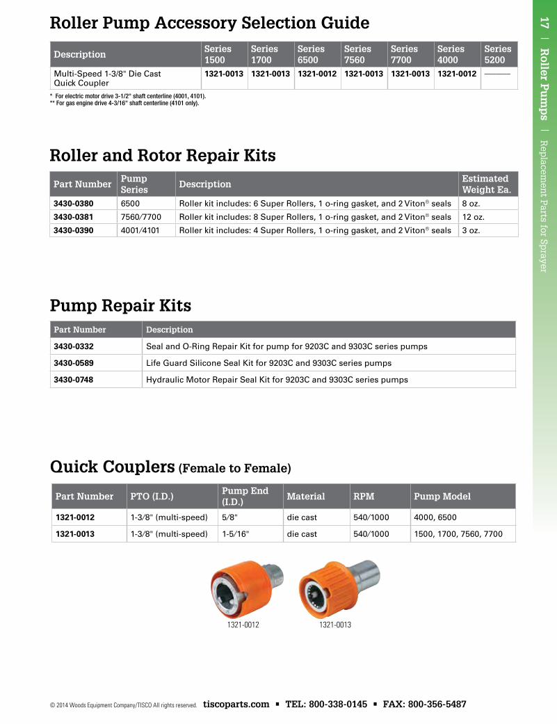
Quick Couplers (Female to Female)
Part Number Description
3430-0332 Seal and O-Ring Repair Kit for pump for 9203C and 9303C series pumps
3430-0589 Life Guard Silicone Seal Kit for 9203C and 9303C series pumps
3430-0748 Hydraulic Motor Repair Seal Kit for 9203C and 9303C series pumps
Pump Repair Kits
Roller Pump Accessory Selection Guide
* For electric motor drive 3-1/2" shaft centerline (4001, 4101).** For gas engine drive 4-3/16" shaft centerline (4101 only).
Description Series 1500
Series 1700
Series 6500
Series 7560
Series 7700
Series 4000
Series 5200
Multi-Speed 1-3/8" Die Cast Quick Coupler
1321-0013 1321-0013 1321-0012 1321-0013 1321-0013 1321-0012 –––––––
Part NumberPump Series
DescriptionEstimated Weight Ea.
3430-0380 6500 Roller kit includes: 6 Super Rollers, 1 o-ring gasket, and 2 Viton® seals 8 oz.
3430-0381 7560⁄7700 Roller kit includes: 8 Super Rollers, 1 o-ring gasket, and 2 Viton® seals 12 oz.
3430-0390 4001⁄4101 Roller kit includes: 4 Super Rollers, 1 o-ring gasket, and 2 Viton® seals 3 oz.
Roller and Rotor Repair Kits
1321-0012 1321-0013
Part Number PTO (I.D.)Pump End (I.D.)
Material RPM Pump Model
1321-0012 1-3⁄8" (multi-speed) 5⁄8" die cast 540⁄1000 4000, 6500
1321-0013 1-3⁄8" (multi-speed) 1-5 ⁄16" die cast 540⁄1000 1500, 1700, 7560, 7700
Rep
lace
men
t P
arts
for
Sp
raye
r |
SH
UR
FL
O D
iap
hra
gm
Pu
mp
s |
18
tiscoparts.com • TEL: 800-338-0145 • FAX: 800-356-5487 © 2014 Woods Equipment Company/TISCO All rights reserved.
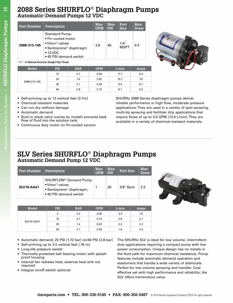
2088 Series SHURFLO® Diaphragm PumpsAutomatic-Demand Pumps 12 VDC
SLV Series SHURFLO® Diaphragm PumpsAutomatic Demand Pump 12 VDC
Part Number Description Max GPM
Max PSI Port Size Max
Draw
SLV10-AA41
SHURFLOW® Demand Pump•Viton® valves•Santoprene® diaphragm,•40PSIdemandswitch
1 30 3/8" Barb 2.5
• Self-priming up to 12 vertical feet [3.7m]• Chemical-resistant materials• Can run dry without damage• Automatic demand• Built-in check valve (varies by model) prevents back
flow of fluid into the solution tank• Continuous duty motor on fin-cooled version
SHURflo 2088 Series diaphragm pumps deliver reliable performance in high flow, moderate pressure applications. They are used in a variety of spot spraying, multi-tip spraying and fertilizer drip applications that require flows of up to 3.6 GPM [13.6 L/min]. They are available in a variety of chemical-resistant materials.
* 1⁄2" - 14 National American Straight Pipe Thread
Part Number Description Max GPM
Max PSI
Port Size
Max Draw
2088-313-145
Standard Pump:•Fincooledmotor•Viton® valves•Santoprene® diaphragm•12VDC •45PSIdemandswitch
3.6 40 1/4" MSPT 9.5
• Automatic demand; 25 PSI [1.72 bar] on/40 PSI [2.8 bar]• Self-priming up to 2.5 vertical feet [.76 m]• Long-life pressure switch• Thermally-protected ball bearing motor with splash-
proof housing• Internal fan radiates heat; external heat sink not
required• Integral on/off switch optional
The SHURflo SLV is ideal for low volume, intermittent-duty applications requiring a compact pump with low power consumption. Unique design has no metals in the fluid path for maximum chemical resistance. Pump features include automatic demand operation and elastomers that handle a wide variety of chemicals. Perfect for low volume spraying and transfer. Cost effective yet with high performance and reliability; the SLV offers tremendous value.
Model PSI BAR GPM L/min Amps
SLV10-AA41
3 0.2 0.90 3.4 1.8
10 0.7 0.73 2.8 2.1
20 1.4 0.62 2.3 2.3
30 2.1 0.49 1.9 2.5
Model PSI BAR GPM L/min Amps
2088-313-145
10 0.7 3.09 11.7 6.4
20 1.4 2.82 10.7 7.6
30 2.1 2.49 9.4 8.7
40 2.8 2.15 8.1 9.5
19 | SH
UR
FL
O M
ini-B
ulk
Ch
emical T
ransfer System
s | R
eplacem
ent P
arts for Sprayer
© 2014 Woods Equipment Company/TISCO All rights reserved. tiscoparts.com • TEL: 800-338-0145 • FAX: 800-356-5487
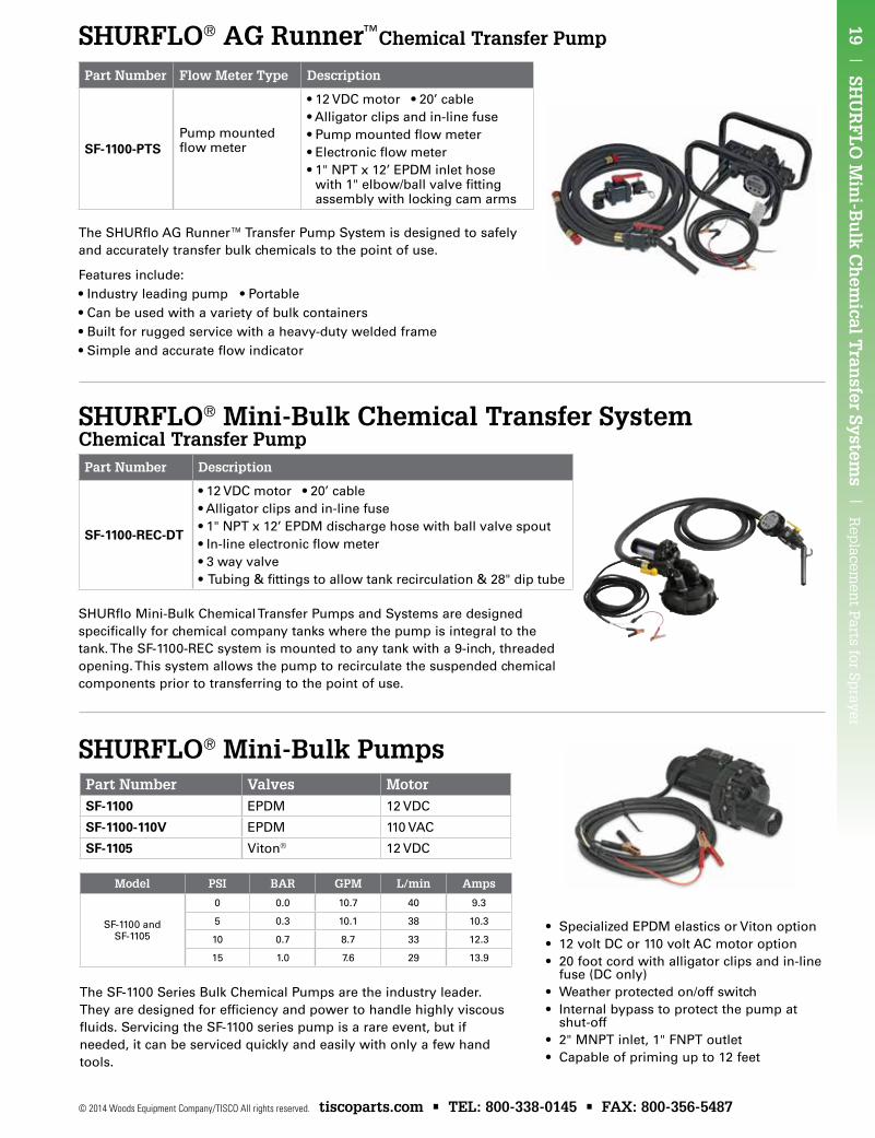
SHURFLO® AG Runner™Chemical Transfer Pump
SHURFLO® Mini-Bulk Chemical Transfer SystemChemical Transfer Pump
SHURFLO® Mini-Bulk Pumps
Part Number Description
SF-1100-REC-DT
•12VDCmotor•20’cable•Alligatorclipsandin-linefuse•1"NPTx12’EPDMdischargehosewithballvalvespout•In-lineelectronicflowmeter•3wayvalve•Tubing&fittingstoallowtankrecirculation&28"diptube
The SHURflo AG Runner™ Transfer Pump System is designed to safely and accurately transfer bulk chemicals to the point of use.
Part Number Flow Meter Type Description
SF-1100-PTSPump mounted flowmeter
•12VDCmotor•20’cable•Alligatorclipsandin-linefuse•Pumpmountedflowmeter•Electronicflowmeter•1"NPTx12’EPDMinlethosewith1"elbow/ballvalvefittingassembly with locking cam arms
SHURflo Mini-Bulk Chemical Transfer Pumps and Systems are designed specifically for chemical company tanks where the pump is integral to the tank. The SF-1100-REC system is mounted to any tank with a 9-inch, threaded opening. This system allows the pump to recirculate the suspended chemical components prior to transferring to the point of use.
Features include:•Industry leading pump •Portable•Can be used with a variety of bulk containers•Built for rugged service with a heavy-duty welded frame•Simple and accurate flow indicator
Model PSI BAR GPM L/min Amps
SF-1100 and SF-1105
0 0.0 10.7 40 9.3
5 0.3 10.1 38 10.3
10 0.7 8.7 33 12.3
15 1.0 7.6 29 13.9
The SF-1100 Series Bulk Chemical Pumps are the industry leader. They are designed for efficiency and power to handle highly viscous fluids. Servicing the SF-1100 series pump is a rare event, but if needed, it can be serviced quickly and easily with only a few hand tools.
Part Number Valves MotorSF-1100 EPDM 12 VDC
SF-1100-110V EPDM 110 VAC
SF-1105 Viton® 12 VDC
• Specialized EPDM elastics or Viton option• 12 volt DC or 110 volt AC motor option• 20 foot cord with alligator clips and in-line
fuse (DC only)• Weather protected on/off switch• Internal bypass to protect the pump at
shut-off• 2" MNPT inlet, 1" FNPT outlet• Capable of priming up to 12 feet
Rep
lace
men
t P
arts
for
Sp
raye
r |
Val
ves
and
Cou
ple
rs |
20
tiscoparts.com • TEL: 800-338-0145 • FAX: 800-356-5487 © 2014 Woods Equipment Company/TISCO All rights reserved.
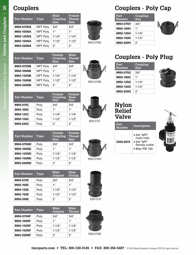
Part Number TypeMale Coupling Size
Female Thread Size
9950-075NA NPT Poly 3/4" 3/4"
9950-100NA NPT Poly 1" 1"
9950-125NA NPT Poly 1-1/4" 1-1/4"
9950-150NA NPT Poly 1-1/2" 1-1/2"
9950-200NA NPT Poly 2" 2"
Part Number TypeFemale Coupling Size
Male Thread Size
9950-075Nb NPT Poly 3/4" 3/4"
9950-100Nb NPT Poly 1" 1"
9950-125Nb NPT Poly 1-1/4" 1-1/4"
9950-150Nb NPT Poly 1-1/2" 1-1/2"
9950-200Nb NPT Poly 2" 2"
Part Number TypeFemale Coupling Size
Female Hose Size
9950-075C Poly 3/4" 3/4"
9950-100C Poly 1" 1"
9950-125C Poly 1-1/4" 1-1/4"
9950-150C Poly 1-1/2" 1-1/2"
9950-200C Poly 2" 2"
Part Number TypeFemale Coupling Size
Female Thread Size
9950-075ND Poly 3/4" 3/4"
9950-100ND Poly 1" 1"
9950-125ND Poly 1-1/4" 1-1/4"
9950-150ND Poly 1-1/2" 1-1/2"
9950-200ND Poly 2" 2"
Part Number Type Male Adapter
Hose Fitting
9950-075E Poly 3/4" 3/4"
9950-100E Poly 1" 1"
9950-125E Poly 1-1/4" 1-1/4"
9950-150E Poly 1-1/2" 1-1/2"
9950-200E Poly 2" 2"
Part Number Type Male Adapter
Male Thread
9950-075NF Poly 3/4" 3/4"
9950-100NF Poly 1" 1"
9950-125NF Poly 1-1/4" 1-1/4"
9950-150NF Poly 1-1/2" 1-1/2"
9950-200NF Poly 2" 2"
Part Number
Coupling Size
9950-075H 3/4"
9950-100H 1"
9950-125H 1-1/4"
9950-150H 1-1/2"
9950-200H 2"
Part Number
Coupling Size
9950-075G 3/4"
9950-100G 1"
9950-125G 1-1/4"
9950-150G 1-1/2"
9950-200G 2"
Couplers Couplers - Poly Cap
Couplers - Poly Plug
9950-075NA
9950-075NB
9950-075C
9950-075ND
9950-075E
9950-075NF
Part Number Description
3300-0015
•3/4"NPTmale inlet
•3/4"NPTfemale outlet
•MaxPSI150
Nylon Relief Valve
21 | V
alves and
Cou
plers |
Rep
lacemen
t Parts for Sp
rayer
© 2014 Woods Equipment Company/TISCO All rights reserved. tiscoparts.com • TEL: 800-338-0145 • FAX: 800-356-5487
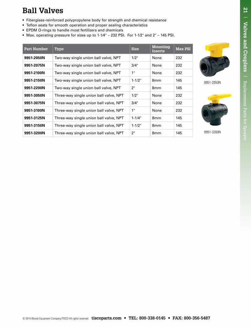
Part Number Type Size Mounting Inserts Max PSI
9951-2050N Two-way single union ball valve, NPT 1/2" None 232
9951-2075N Two-way single union ball valve, NPT 3/4" None 232
9951-2100N Two-way single union ball valve, NPT 1" None 232
9951-2150N Two-way single union ball valve, NPT 1-1/2" 8mm 145
9951-2200N Two-way single union ball valve, NPT 2" 8mm 145
9951-3050N Three-way single union ball valve, NPT 1/2" None 232
9951-3075N Three-way single union ball valve, NPT 3/4" None 232
9951-3100N Three-way single union ball valve, NPT 1" None 232
9951-3125N Three-way single union ball valve, NPT 1-1/4" 8mm 145
9951-3150N Three-way single union ball valve, NPT 1-1/2" 8mm 145
9951-3200N Three-way single union ball valve, NPT 2" 8mm 145
9951-2050N
9951-3200N
Ball Valves• Fiberglass-reinforced polypropylene body for strength and chemical resistance• Teflon seats for smooth operation and proper sealing characteristics• EPDM O-rings to handle most fertilizers and chemicals• Max. operating pressure for sizes up to 1-1⁄4" – 232 PSI. For 1-1⁄2" and 2" – 145 PSI.
Rep
lace
men
t P
arts
for
Sp
raye
r |
Fit
tin
gs
| 2
2
tiscoparts.com • TEL: 800-338-0145 • FAX: 800-356-5487 © 2014 Woods Equipment Company/TISCO All rights reserved.
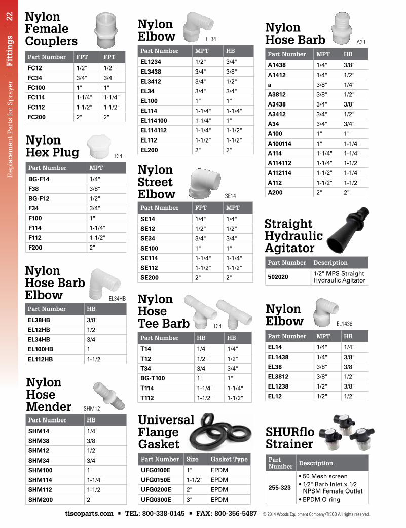
Part Number MPT
bG-F14 1/4"
F38 3/8"
bG-F12 1/2"
F34 3/4"
F100 1"
F114 1-1/4"
F112 1-1/2"
F200 2"
Part Number HB
EL38Hb 3/8"
EL12Hb 1/2"
EL34Hb 3/4"
EL100Hb 1"
EL112Hb 1-1/2"
Part Number HB
SHM14 1/4"
SHM38 3/8"
SHM12 1/2"
SHM34 3/4"
SHM100 1"
SHM114 1-1/4"
SHM112 1-1/2"
SHM200 2"
Part Number MPT HB
EL1234 1/2" 3/4"
EL3438 3/4" 3/8"
EL3412 3/4" 1/2"
EL34 3/4" 3/4"
EL100 1" 1"
EL114 1-1/4" 1-1/4"
EL114100 1-1/4" 1"
EL114112 1-1/4" 1-1/2"
EL112 1-1/2" 1-1/2"
EL200 2" 2"
Part Number FPT MPT
SE14 1/4" 1/4"
SE12 1/2" 1/2"
SE34 3/4" 3/4"
SE100 1" 1"
SE114 1-1/4" 1-1/4"
SE112 1-1/2" 1-1/2"
SE200 2" 2"
Part Number HB HB
T14 1/4" 1/4"
T12 1/2" 1/2"
T34 3/4" 3/4"
bG-T100 1" 1"
T114 1-1/4" 1-1/4"
T112 1-1/2" 1-1/2"
Nylon Hex Plug
Nylon Hose Barb Elbow
Nylon Hose Mender
Nylon Elbow
Nylon Street Elbow
Nylon Hose Tee Barb
F34
EL34HB
SHM12
T34
EL34
SE14
Part Number FPT FPT
FC12 1/2" 1/2"
FC34 3/4" 3/4"
FC100 1" 1"
FC114 1-1/4" 1-1/4"
FC112 1-1/2" 1-1/2"
FC200 2" 2"
Nylon Female Couplers
Part Number Size Gasket Type
uFG0100E 1" EPDM
uFG0150E 1-1/2" EPDM
uFG0200E 2" EPDM
uFG0300E 3" EPDM
Universal Flange Gasket
Part Number Description
255-323
•50Meshscreen•1⁄2"BarbInletx1⁄2
NPSM Female Outlet•EPDMO-ring
Part Number MPT HB
EL14 1/4" 1/4"
EL1438 1/4" 3/8"
EL38 3/8" 3/8"
EL3812 3/8" 1/2"
EL1238 1/2" 3/8"
EL12 1/2" 1/2"
Part Number MPT HB
A1438 1/4" 3/8"
A1412 1/4" 1/2"
a 3/8" 1/4"
A3812 3/8" 1/2"
A3438 3/4" 3/8"
A3412 3/4" 1/2"
A34 3/4" 3/4"
A100 1" 1"
A100114 1" 1-1/4"
A114 1-1/4" 1-1/4"
A114112 1-1/4" 1-1/2"
A112114 1-1/2" 1-1/4"
A112 1-1/2" 1-1/2"
A200 2" 2"
Part Number Description
502020 1/2" MPS Straight Hydraulic Agitator
SHURflo Strainer
Nylon Elbow
Nylon Hose Barb
Straight Hydraulic Agitator
EL1438
A38
23 | F
itting
s | R
eplacem
ent P
arts for Sprayer
© 2014 Woods Equipment Company/TISCO All rights reserved. tiscoparts.com • TEL: 800-338-0145 • FAX: 800-356-5487
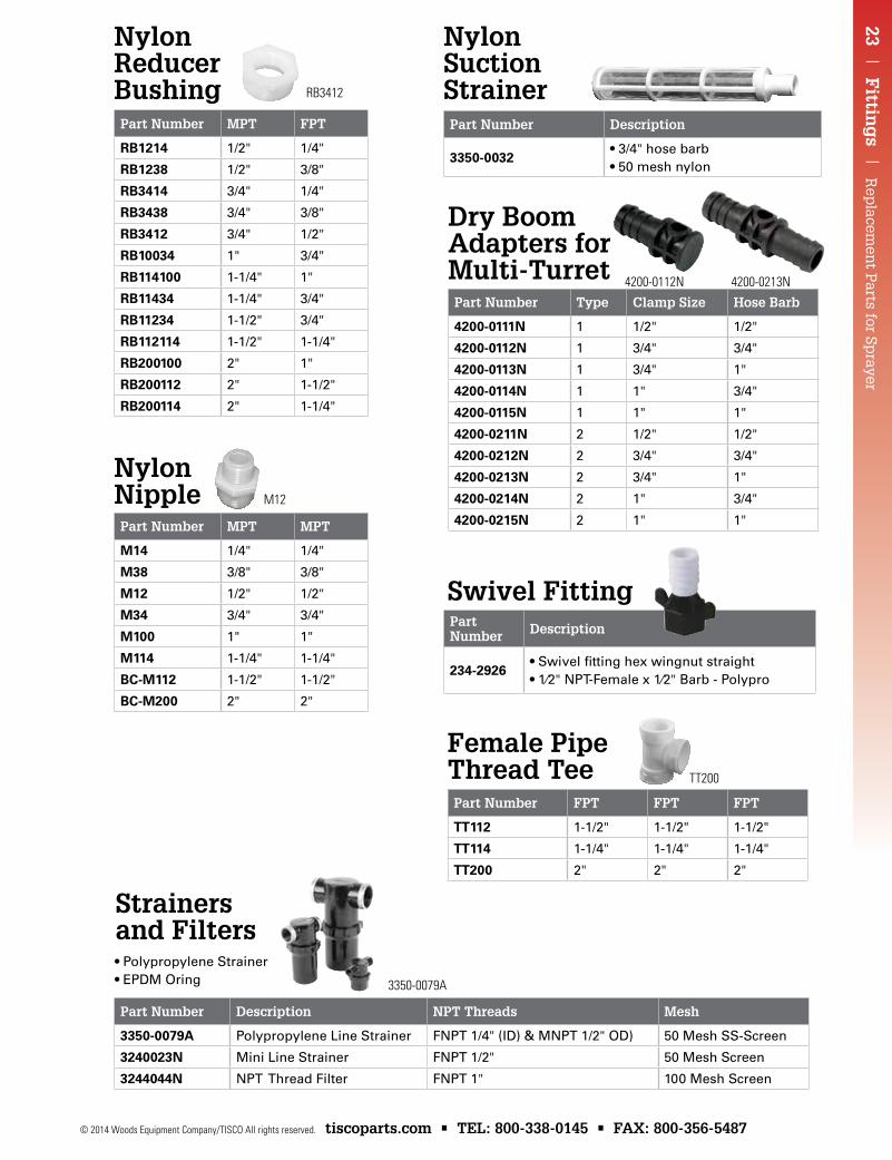
Part Number Description
255-323
•50Meshscreen•1⁄2"BarbInletx1⁄2
NPSM Female Outlet•EPDMO-ring
Part Number FPT FPT FPT
TT112 1-1/2" 1-1/2" 1-1/2"
TT114 1-1/4" 1-1/4" 1-1/4"
TT200 2" 2" 2"
Part Number MPT FPT
Rb1214 1/2" 1/4"
Rb1238 1/2" 3/8"
Rb3414 3/4" 1/4"
Rb3438 3/4" 3/8"
Rb3412 3/4" 1/2"
Rb10034 1" 3/4"
Rb114100 1-1/4" 1"
Rb11434 1-1/4" 3/4"
Rb11234 1-1/2" 3/4"
Rb112114 1-1/2" 1-1/4"
Rb200100 2" 1"
Rb200112 2" 1-1/2"
Rb200114 2" 1-1/4"
Part Number MPT MPT
M14 1/4" 1/4"
M38 3/8" 3/8"
M12 1/2" 1/2"
M34 3/4" 3/4"
M100 1" 1"
M114 1-1/4" 1-1/4"
bC-M112 1-1/2" 1-1/2"
bC-M200 2" 2"
Part Number Description
234-2926•Swivelfittinghexwingnutstraight•1⁄2"NPT-Femalex1⁄2"Barb-Polypro
Part Number Type Clamp Size Hose Barb
4200-0111N 1 1/2" 1/2"
4200-0112N 1 3/4" 3/4"
4200-0113N 1 3/4" 1"
4200-0114N 1 1" 3/4"
4200-0115N 1 1" 1"
4200-0211N 2 1/2" 1/2"
4200-0212N 2 3/4" 3/4"
4200-0213N 2 3/4" 1"
4200-0214N 2 1" 3/4"
4200-0215N 2 1" 1"
Part Number Description
3350-0032•3/4"hosebarb•50meshnylon
Part Number Description NPT Threads Mesh
3350-0079A Polypropylene Line Strainer FNPT 1/4" (ID) & MNPT 1/2" OD) 50 Mesh SS-Screen
3240023N Mini Line Strainer FNPT 1/2" 50 Mesh Screen
3244044N NPT Thread Filter FNPT 1" 100 Mesh Screen
•PolypropyleneStrainer•EPDMOring
Female Pipe Thread Tee
Nylon Reducer Bushing
Nylon Nipple
Swivel Fitting
Nylon Suction Strainer
Strainers and Filters
Dry Boom Adapters for Multi-Turret 4200-0112N 4200-0213N
3350-0079A
TT200
RB3412
M12
Rep
lace
men
t P
arts
for
Sp
raye
r |
Gau
ges
| 2
4
tiscoparts.com • TEL: 800-338-0145 • FAX: 800-356-5487 © 2014 Woods Equipment Company/TISCO All rights reserved.
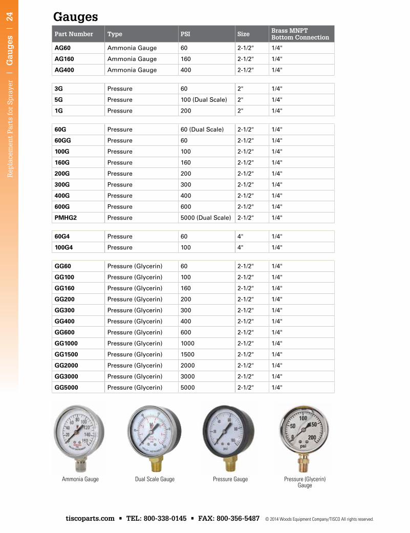
Part Number Type PSI Size Brass MNPT Bottom Connection
AG60 Ammonia Gauge 60 2-1/2" 1/4"
AG160 Ammonia Gauge 160 2-1/2" 1/4"
AG400 Ammonia Gauge 400 2-1/2" 1/4"
3G Pressure 60 2" 1/4"
5G Pressure 100 (Dual Scale) 2" 1/4"
1G Pressure 200 2" 1/4"
60G Pressure 60 (Dual Scale) 2-1/2" 1/4"
60GG Pressure 60 2-1/2" 1/4"
100G Pressure 100 2-1/2" 1/4"
160G Pressure 160 2-1/2" 1/4"
200G Pressure 200 2-1/2" 1/4"
300G Pressure 300 2-1/2" 1/4"
400G Pressure 400 2-1/2" 1/4"
600G Pressure 600 2-1/2" 1/4"
PMHG2 Pressure 5000 (Dual Scale) 2-1/2" 1/4"
60G4 Pressure 60 4" 1/4"
100G4 Pressure 100 4" 1/4"
GG60 Pressure (Glycerin) 60 2-1/2" 1/4"
GG100 Pressure (Glycerin) 100 2-1/2" 1/4"
GG160 Pressure (Glycerin) 160 2-1/2" 1/4"
GG200 Pressure (Glycerin) 200 2-1/2" 1/4"
GG300 Pressure (Glycerin) 300 2-1/2" 1/4"
GG400 Pressure (Glycerin) 400 2-1/2" 1/4"
GG600 Pressure (Glycerin) 600 2-1/2" 1/4"
GG1000 Pressure (Glycerin) 1000 2-1/2" 1/4"
GG1500 Pressure (Glycerin) 1500 2-1/2" 1/4"
GG2000 Pressure (Glycerin) 2000 2-1/2" 1/4"
GG3000 Pressure (Glycerin) 3000 2-1/2" 1/4"
GG5000 Pressure (Glycerin) 5000 2-1/2" 1/4"
Ammonia Gauge Dual Scale Gauge Pressure Gauge Pressure (Glycerin) Gauge
Gauges
25 | H
ose | R
eplacem
ent P
arts for Sprayer
© 2014 Woods Equipment Company/TISCO All rights reserved. tiscoparts.com • TEL: 800-338-0145 • FAX: 800-356-5487
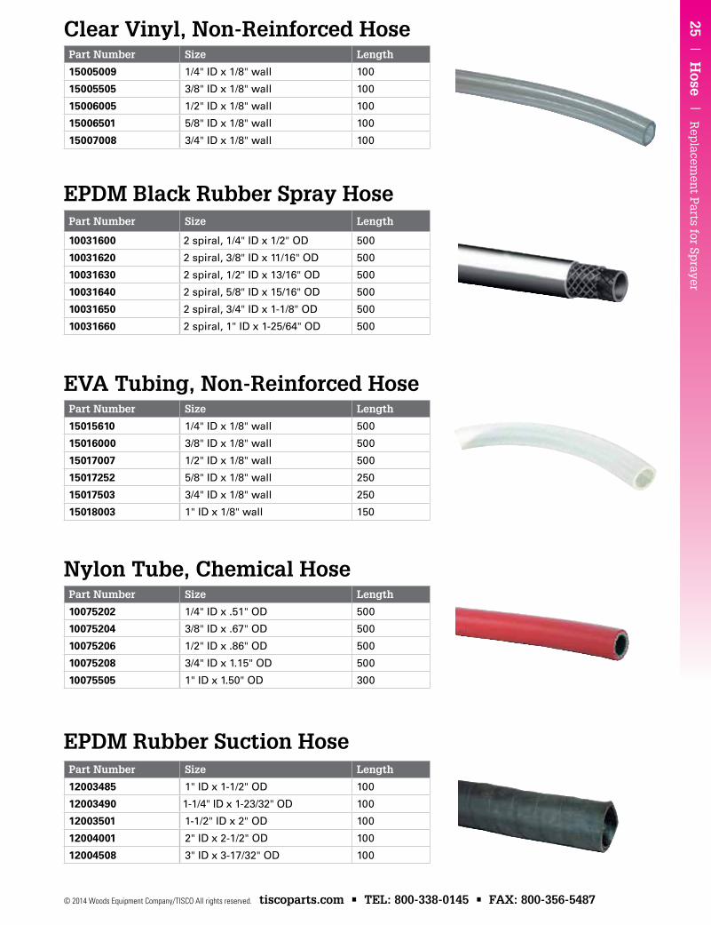
Part Number Size Length
12003485 1" ID x 1-1/2" OD 100
12003490 1-1/4" ID x 1-23/32" OD 100
12003501 1-1/2" ID x 2" OD 100
12004001 2" ID x 2-1/2" OD 100
12004508 3" ID x 3-17/32" OD 100
Clear Vinyl, Non-Reinforced Hose
EPDM Black Rubber Spray Hose
EVA Tubing, Non-Reinforced Hose
Nylon Tube, Chemical Hose
EPDM Rubber Suction Hose
Part Number Size Length
15005009 1/4" ID x 1/8" wall 100
15005505 3/8" ID x 1/8" wall 100
15006005 1/2" ID x 1/8" wall 100
15006501 5/8" ID x 1/8" wall 100
15007008 3/4" ID x 1/8" wall 100
Part Number Size Length
10031600 2 spiral, 1/4" ID x 1/2" OD 500
10031620 2 spiral, 3/8" ID x 11/16" OD 500
10031630 2 spiral, 1/2" ID x 13/16" OD 500
10031640 2 spiral, 5/8" ID x 15/16" OD 500
10031650 2 spiral, 3/4" ID x 1-1/8" OD 500
10031660 2 spiral, 1" ID x 1-25/64" OD 500
Part Number Size Length
15015610 1/4" ID x 1/8" wall 500
15016000 3/8" ID x 1/8" wall 500
15017007 1/2" ID x 1/8" wall 500
15017252 5/8" ID x 1/8" wall 250
15017503 3/4" ID x 1/8" wall 250
15018003 1" ID x 1/8" wall 150
Part Number Size Length
10075202 1/4" ID x .51" OD 500
10075204 3/8" ID x .67" OD 500
10075206 1/2" ID x .86" OD 500
10075208 3/4" ID x 1.15" OD 500
10075505 1" ID x 1.50" OD 300
Rep
lace
men
t P
arts
for
Sp
raye
r |
Sel
ecti
ng
th
e R
igh
t Sp
ray
Tip
| 2
6
tiscoparts.com • TEL: 800-338-0145 • FAX: 800-356-5487 © 2014 Woods Equipment Company/TISCO All rights reserved.
Selecting the Right Spray Tip
To be effective, a pesticide must be applied properly. To select the correct spray tip for the job, first fully read the pesticide label and look for information on tip type, application rate, spray quality, and environmental restrictions. Then…
a) Check which type of spraying technique you will be using – broadcast or banding.
b) Check your sprayer speed.
c) Select the application rate from the pesticide label.
d) Determine the flow rate (GPM) needed for the spray tip, or use the application rate (GPA) chart for the desired tip.
e) Select the pattern type.
f) Select tip size and pressure that provides the desired flow rate and application rate.
g) Check the spray quality tables to be sure the spray tip and pressure create the droplet spectrum you require.
A – Spraying Technique:
Broadcast spraying is when the entire field is to be treated. The width that each tip sprays, adjusted for spray overlap, is the distance between tips on the spray boom.
Band spraying is when planted rows or unplanted gaps are treated. The width that each tip sprays is the width of the treated band. Refer to page 174. B – Sprayer Speed:
Forward speed of the spraying machine should be measured accurately. Radar or ultrasound speed sensors should be calibrated after installation or servicing. Wheel-driven speedometers should be calibrated whenever the driving surface changes, such as after cultivation. Speed can be determined if it is known how long it takes to drive a measured distance:
Refer to page 172.
distance (feet) x 60 speed in MPH = time (seconds) x 88
Improved vehicle design means that speeds up to 20 MPH are now possible. Higher speeds (10-20 MPH) improve work rates and timeliness; lower speeds (5-10 MPH) give improved canopy penetration and make spray drift control simpler. C – Application Rate:
Read the pesticide label closely to determine an appropriate spray application rate. If a range of acceptable application rates is listed, choose a rate that best matches your situation.
Visit sprayit.hypropumps.com for Hypro's online tip calculator.
27 | Selectin
g th
e Rig
ht Sp
ray Tip
| R
eplacem
ent P
arts for Sprayer
© 2014 Woods Equipment Company/TISCO All rights reserved. tiscoparts.com • TEL: 800-338-0145 • FAX: 800-356-5487
Selecting the Right Spray Tip
D – Flow Rate:
Determine the exact flow required from each tip by calculating: Refer to page 172.
GPA x MPH x tip spacing (inches) GPM =
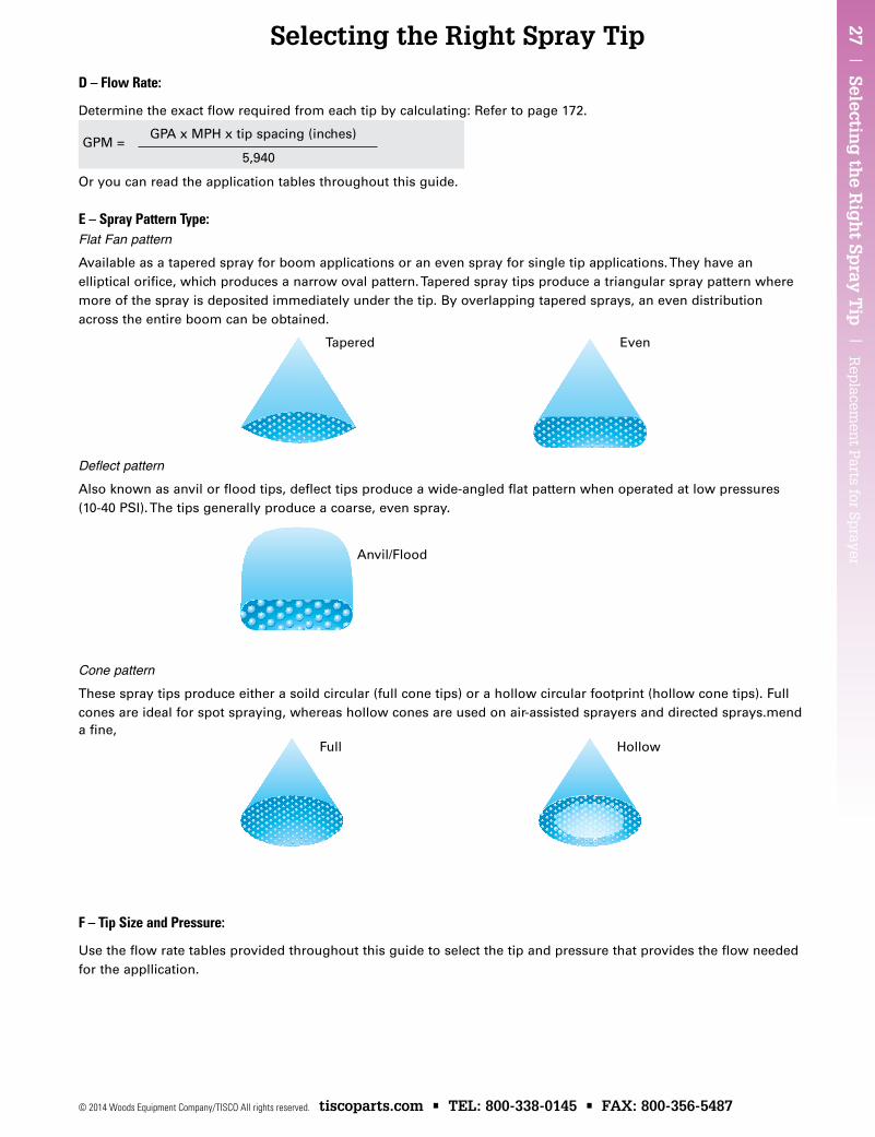
Or you can read the application tables throughout this guide. E – Spray Pattern Type:Flat Fan patternAvailable as a tapered spray for boom applications or an even spray for single tip applications. They have an elliptical orifice, which produces a narrow oval pattern. Tapered spray tips produce a triangular spray pattern where more of the spray is deposited immediately under the tip. By overlapping tapered sprays, an even distribution across the entire boom can be obtained.
Deflect patternAlso known as anvil or flood tips, deflect tips produce a wide-angled flat pattern when operated at low pressures (10-40 PSI). The tips generally produce a coarse, even spray.
Cone patternThese spray tips produce either a soild circular (full cone tips) or a hollow circular footprint (hollow cone tips). Full cones are ideal for spot spraying, whereas hollow cones are used on air-assisted sprayers and directed sprays.mend a fine,
F – Tip Size and Pressure:
Use the flow rate tables provided throughout this guide to select the tip and pressure that provides the flow needed for the appllication.
Anvil/Flood
Full Hollow
EvenTapered
5,940
Rep
lace
men
t P
arts
for
Sp
raye
r |
Sel
ecti
ng
th
e R
igh
t Sp
ray
Tip
| 2
8
tiscoparts.com • TEL: 800-338-0145 • FAX: 800-356-5487 © 2014 Woods Equipment Company/TISCO All rights reserved.
Selecting the Right Spray Tip
The ASABE S572.1 standard uses eight droplet classification categories, six of which are common for agriculture and horticulture:
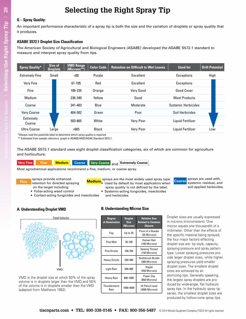
Very Fine , Fine , Medium , Coarse , Very Coarse and Extremely Coarse .Most agrochemical applications recommend a fine, medium, or coarse spray.
Spray Quality* Size of Droplets
VMD Range (Microns**) Color Code Retention on Difficult to Wet Leaves Used for Drift Potential
Extremely Fine Small <60 Purple Excellent Exceptions High
Very Fine 61-105 Red Excellent Exceptions
Fine 106-235 Orange Very Good Good Cover
Medium 236-340 Yellow Good Most Products
Coarse 341-403 Blue Moderate Systemic Herbicides
Very Coarse 404-502 Green Poor Soil Herbicides
Extremely Coarse
503-665 White Very Poor Liquid Fertilizer
Ultra Coarse Large >665 Black Very Poor Liquid Fertilizer Low*Always read the pesticide label to determine which spray quality is required.** Estimated from sample reference graph in ASABE/ANSI/ASAE Standard S572.1.
VMD is the droplet size at which 50% of the spray volume is in droplets larger than the VMD and 50% of the volume is in droplets smaller than the VMD (adapted from Matthews 1992).
Droplet sizes are usually expressed in microns (micrometers). One micron equals one thousandth of a millimeter. Other than the effects of the specific material being sprayed, the four major factors effecting droplet size are: tip style, capacity, spraying pressure and spray pattern type. Lower spraying pressures pro-vide larger droplet sizes, while higher spraying pressures yield smaller droplet sizes. The smallest droplet sizes are achieved by air atomizing tips. Generally speaking, the largest spray droplets are pro-duced by wide-angle, flat hydraulic spray tips. In the hydraulic spray tip series, the smallest droplet sizes are produced by hollow-cone spray tips.
G – Spray Quality:
An important performance characteristic of a spray tip is both the size and the variation of droplets or spray quality that it produces.
ASABE S572.1 Droplet Size ClassificationThe American Society of Agricultural and Biological Engineers (ASABE) developed the ASABE S572.1 standard to measure and interpret spray quality from tips.
Coarse sprays are used with,
systemic residual, and soil-applied herbicides.
Medium sprays are the most widely used spray type.
•Usedbydefaultbymostapplicatorswhen spray quality is not defined by the label. •Systemic-actingfungicides,insecticides and herbicides.
Fine sprays provide enhanced
retention for directed spraying on the target including: •Foliar-actingweedcontrol •Contact-actingfungicidesandinsecticides
Degreeof Atomization
Droplet Size
(Microns)
Relative Size Related to Common
Objects
Fog Up to 25Point of a Needle
(25 Microns)
Fine Mist 20-100Human Hair
(100 Microns)
Fine Drizzle 100-250Sewing Thread (150 Microns)
Heavy Drizzle 250-500Toothbrush Bristle
(300 Microns)
Light Rain 500-800Staple
(550 Microns)
Heavy Rain 800-1000Paper Clip
(850 Microns)
Thunderstorm Rain
1000-4000#2 Pencil Lead(2000 Microns)
Total Volume
VMD
A. Understanding Droplet VMD B. Understanding Micron Size
29 | Selectin
g th
e Rig
ht Sp
ray Tip
| R
eplacem
ent P
arts for Sprayer
© 2014 Woods Equipment Company/TISCO All rights reserved. tiscoparts.com • TEL: 800-338-0145 • FAX: 800-356-5487
Spray Tip Selection Guide
Folia
rC
onta
ct
Folia
rSy
stem
ic
Soi
lA
pplie
d
Dra
ftC
ontr
ol
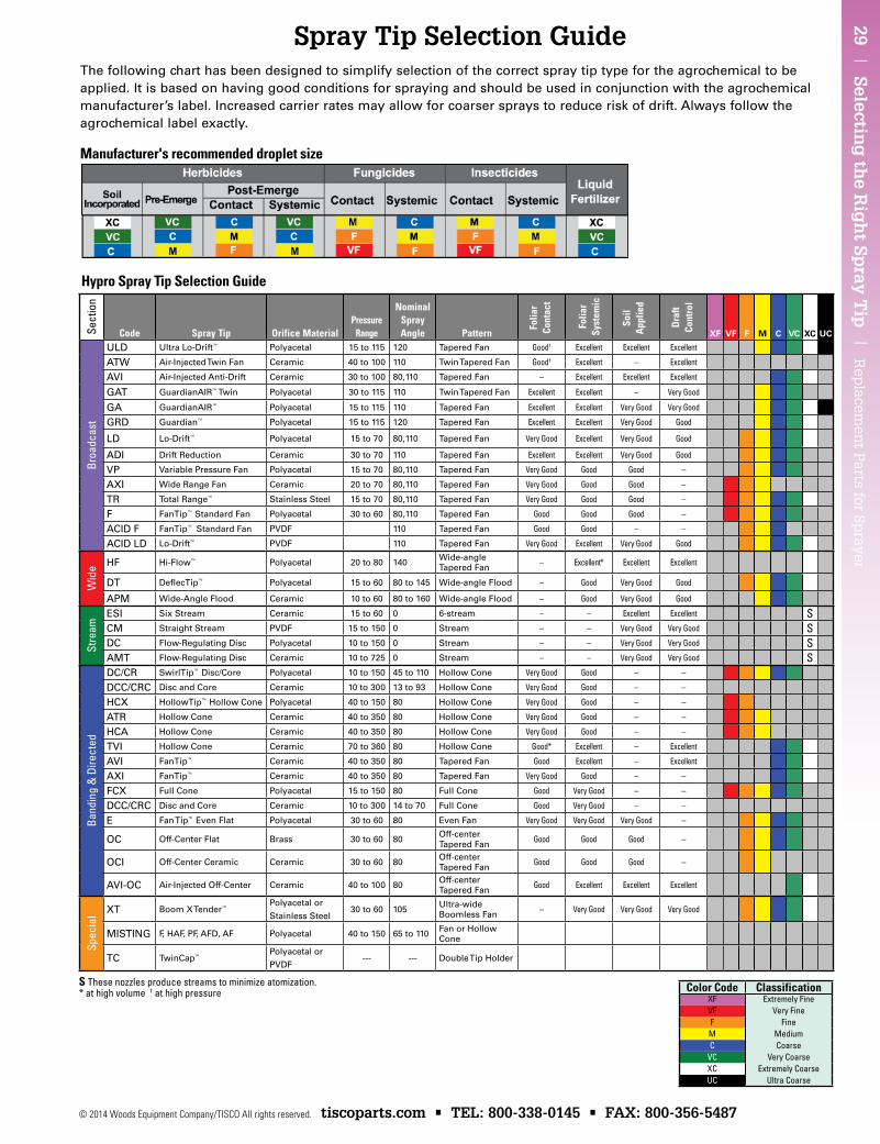
The following chart has been designed to simplify selection of the correct spray tip type for the agrochemical to be applied. It is based on having good conditions for spraying and should be used in conjunction with the agrochemical manufacturer’s label. Increased carrier rates may allow for coarser sprays to reduce risk of drift. Always follow the agrochemical label exactly.
Sect
ion
Code Spray Tip Orifice MaterialPressure
Range
Nominal Spray Angle Pattern XF VF F M C VC XC uC
Broa
dcas
t
ULD Ultra Lo-Drift™ Polyacetal 15 to 115 120 Tapered Fan Good† Excellent Excellent Excellent
ATW Air-Injected Twin Fan Ceramic 40 to 100 110 Twin Tapered Fan Good† Excellent – Excellent
AVI Air-Injected Anti-Drift Ceramic 30 to 100 80,110 Tapered Fan – Excellent Excellent Excellent
GAT GuardianAIR™ Twin Polyacetal 30 to 115 110 Twin Tapered Fan Excellent Excellent – Very Good
GA GuardianAIR™ Polyacetal 15 to 115 110 Tapered Fan Excellent Excellent Very Good Very Good
GRD Guardian™ Polyacetal 15 to 115 120 Tapered Fan Excellent Excellent Very Good Good
LD Lo-Drift™ Polyacetal 15 to 70 80,110 Tapered Fan Very Good Excellent Very Good Good
ADI Drift Reduction Ceramic 30 to 70 110 Tapered Fan Excellent Excellent Very Good Good
VP Variable Pressure Fan Polyacetal 15 to 70 80,110 Tapered Fan Very Good Good Good –
AXI Wide Range Fan Ceramic 20 to 70 80,110 Tapered Fan Very Good Good Good –
TR Total Range™ Stainless Steel 15 to 70 80,110 Tapered Fan Very Good Good Good –
F FanTip™ Standard Fan Polyacetal 30 to 60 80,110 Tapered Fan Good Good Good –
ACID F FanTip™ Standard Fan PVDF 110 Tapered Fan Good Good – –
ACID LD Lo-Drift™ PVDF 110 Tapered Fan Very Good Excellent Very Good Good
Wid
e HF Hi-Flow™ Polyacetal 20 to 80 140 Wide-angle Tapered Fan – Excellent* Excellent Excellent
DT DeflecTip™ Polyacetal 15 to 60 80 to 145 Wide-angle Flood – Good Very Good Good
APM Wide-Angle Flood Ceramic 10 to 60 80 to 160 Wide-angle Flood – Good Very Good Good
Stre
am
ESI Six Stream Ceramic 15 to 60 0 6-stream – – Excellent Excellent SCM Straight Stream PVDF 15 to 150 0 Stream – – Very Good Very Good SDC Flow-Regulating Disc Polyacetal 10 to 150 0 Stream – – Very Good Very Good SAMT Flow-Regulating Disc Ceramic 10 to 725 0 Stream – – Very Good Very Good S
Band
ing
& D
irect
ed
DC/CR SwirlTip™ Disc/Core Polyacetal 10 to 150 45 to 110 Hollow Cone Very Good Good – –
DCC/CRC Disc and Core Ceramic 10 to 300 13 to 93 Hollow Cone Very Good Good – –
HCX HollowTip™ Hollow Cone Polyacetal 40 to 150 80 Hollow Cone Very Good Good – –
ATR Hollow Cone Ceramic 40 to 350 80 Hollow Cone Very Good Good – –
HCA Hollow Cone Ceramic 40 to 350 80 Hollow Cone Very Good Good – –
TVI Hollow Cone Ceramic 70 to 360 80 Hollow Cone Good* Excellent – Excellent
AVI FanTip™ Ceramic 40 to 350 80 Tapered Fan Good Excellent – Excellent
AXI FanTip™ Ceramic 40 to 350 80 Tapered Fan Very Good Good – –
FCX Full Cone Polyacetal 15 to 150 80 Full Cone Good Very Good – –
DCC/CRC Disc and Core Ceramic 10 to 300 14 to 70 Full Cone Good Very Good – –
E Fan Tip™ Even Flat Polyacetal 30 to 60 80 Even Fan Very Good Very Good Very Good –
OC Off-Center Flat Brass 30 to 60 80 Off-center Tapered Fan Good Good Good –
OCI Off-Center Ceramic Ceramic 30 to 60 80 Off-center Tapered Fan Good Good Good –
AVI-OC Air-Injected Off-Center Ceramic 40 to 100 80 Off-center Tapered Fan Good Excellent Excellent Excellent
Spec
ial XT Boom X Tender™
Polyacetal or
Stainless Steel30 to 60 105 Ultra-wide
Boomless Fan – Very Good Very Good Very Good
MISTING F, HAF, PF, AFD, AF Polyacetal 40 to 150 65 to 110 Fan or Hollow Cone
TC TwinCap™Polyacetal or
PVDF--- --- Double Tip Holder
Color Code ClassificationXF Extremely FineVF Very FineF FineM MediumC Coarse
VC Very CoarseXC Extremely CoarseUC Ultra Coarse
S These nozzles produce streams to minimize atomization.* at high volume † at high pressure
Manufacturer's recommended droplet size
Hypro Spray Tip Selection Guide
Folia
rCo
ntac
t
Folia
rSy
stem
ic
Soil
App
lied
Dra
ftCo
ntro
l
Rep
lace
men
t P
arts
for
Sp
raye
r |
Sel
ecti
ng
th
e R
igh
t Sp
ray
Tip
| 3
0
tiscoparts.com • TEL: 800-338-0145 • FAX: 800-356-5487 © 2014 Woods Equipment Company/TISCO All rights reserved.
Wear and Chemical Compatibility
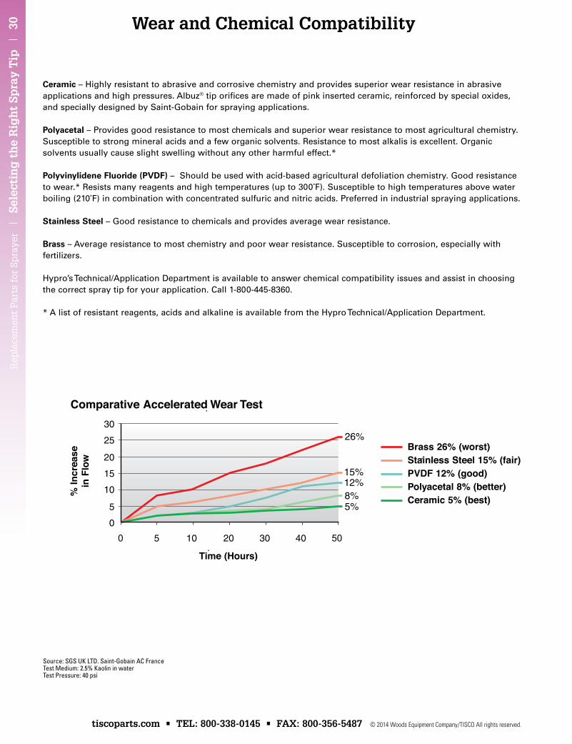
Source: SGS UK LTD. Saint-Gobain AC FranceTest Medium: 2.5% Kaolin in waterTest Pressure: 40 psi
Comparative Accelerated Wear Test
Time (Hours)
% In
crea
sein
Flo
w
Brass 26% (worst)Stainless Steel 15% (fair)PVDF 12% (good)Polyacetal 8% (better)Ceramic 5% (best)
Ceramic – Highly resistant to abrasive and corrosive chemistry and provides superior wear resistance in abrasive applications and high pressures. Albuz® tip orifices are made of pink inserted ceramic, reinforced by special oxides, and specially designed by Saint-Gobain for spraying applications.
Polyacetal – Provides good resistance to most chemicals and superior wear resistance to most agricultural chemistry. Susceptible to strong mineral acids and a few organic solvents. Resistance to most alkalis is excellent. Organic solvents usually cause slight swelling without any other harmful effect.*
Polyvinylidene Fluoride (PVDF) – Should be used with acid-based agricultural defoliation chemistry. Good resistance to wear.* Resists many reagents and high temperatures (up to 300°F). Susceptible to high temperatures above water boiling (210°F) in combination with concentrated sulfuric and nitric acids. Preferred in industrial spraying applications.
Stainless Steel – Good resistance to chemicals and provides average wear resistance.
brass – Average resistance to most chemistry and poor wear resistance. Susceptible to corrosion, especially with fertilizers.
Hypro’s Technical/Application Department is available to answer chemical compatibility issues and assist in choosing the correct spray tip for your application. Call 1-800-445-8360.
* A list of resistant reagents, acids and alkaline is available from the Hypro Technical/Application Department.
31 | Sp
raying
Systems C
ross Referen
ce | R
eplacem
ent P
arts for Sprayer
© 2014 Woods Equipment Company/TISCO All rights reserved. tiscoparts.com • TEL: 800-338-0145 • FAX: 800-356-5487
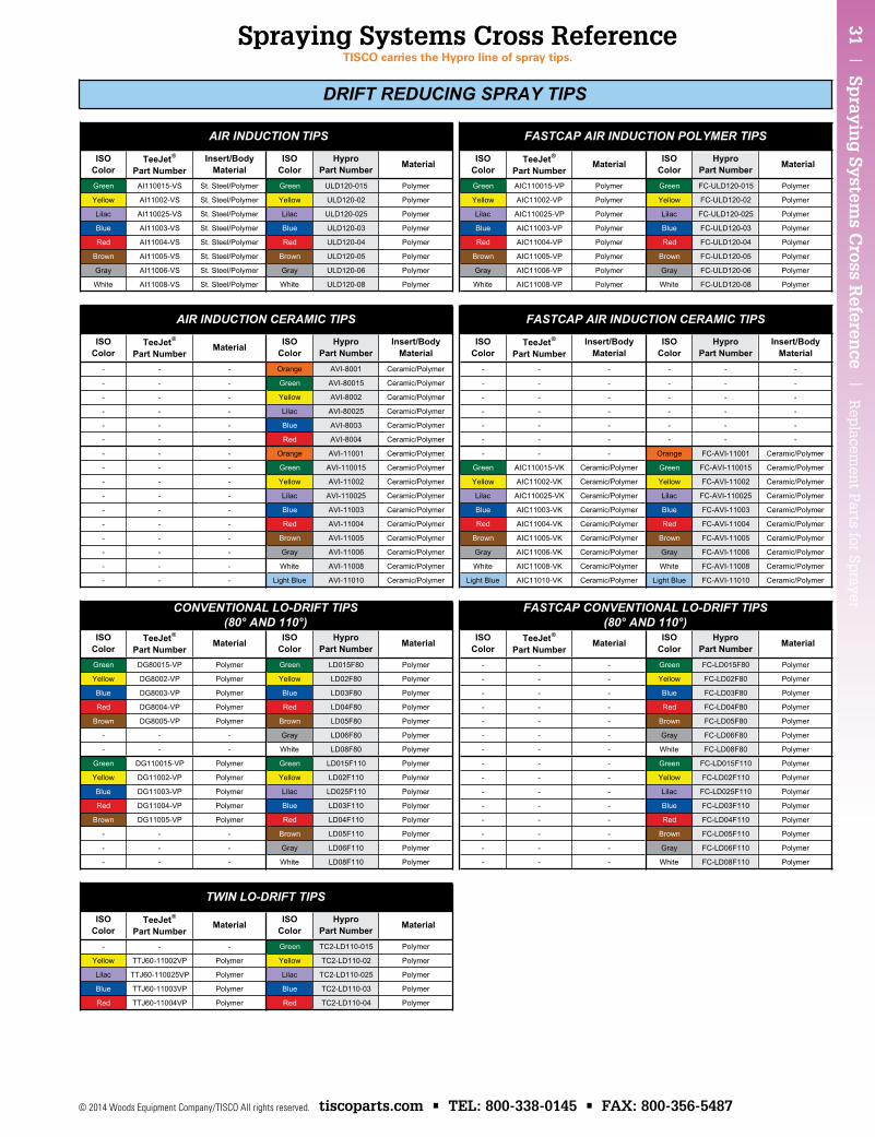
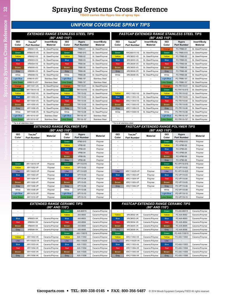
Spraying Systems Cross ReferenceTISCo carries the Hypro line of spray tips.
Rep
lace
men
t P
arts
for
Sp
raye
r |
Sp
rayi
ng
Sys
tem
s C
ross
Ref
eren
ce |
32
tiscoparts.com • TEL: 800-338-0145 • FAX: 800-356-5487 © 2014 Woods Equipment Company/TISCO All rights reserved.
Spraying Systems Cross ReferenceTISCo carries the Hypro line of spray tips.
33 | Sp
raying
Systems C
ross Referen
ce | R
eplacem
ent P
arts for Sprayer
© 2014 Woods Equipment Company/TISCO All rights reserved. tiscoparts.com • TEL: 800-338-0145 • FAX: 800-356-5487
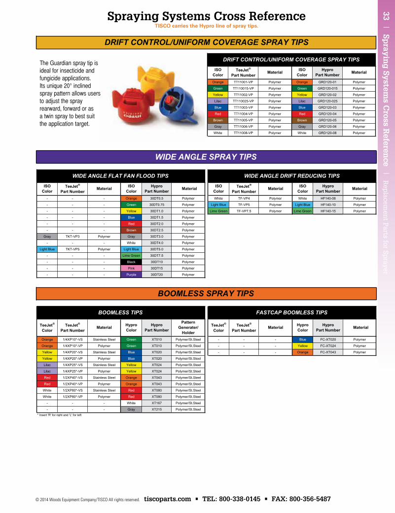
Spraying Systems Cross ReferenceTISCo carries the Hypro line of spray tips.
The Guardian spray tip isideal for insecticide andfungicide applications.Its unique 20° inclinedspray pattern allows usersto adjust the sprayrearward, forward or asa twin spray to best suitthe application target.
Rep
lace
men
t P
arts
for
Sp
raye
r |
Sp
rayi
ng
Sys
tem
s C
ross
Ref
eren
ce |
34
tiscoparts.com • TEL: 800-338-0145 • FAX: 800-356-5487 © 2014 Woods Equipment Company/TISCO All rights reserved.
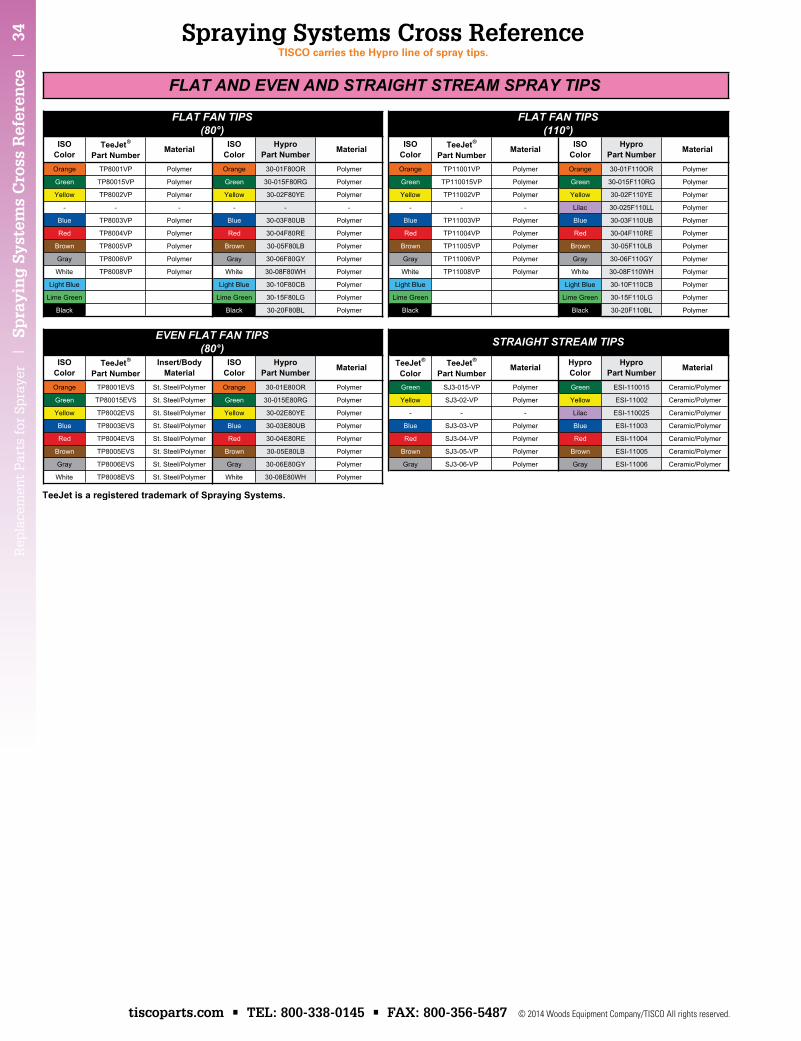
Spraying Systems Cross ReferenceTISCo carries the Hypro line of spray tips.
35 | T
ips an
d N
ozzles | R
eplacem
ent P
arts for Sprayer
© 2014 Woods Equipment Company/TISCO All rights reserved. tiscoparts.com • TEL: 800-338-0145 • FAX: 800-356-5487
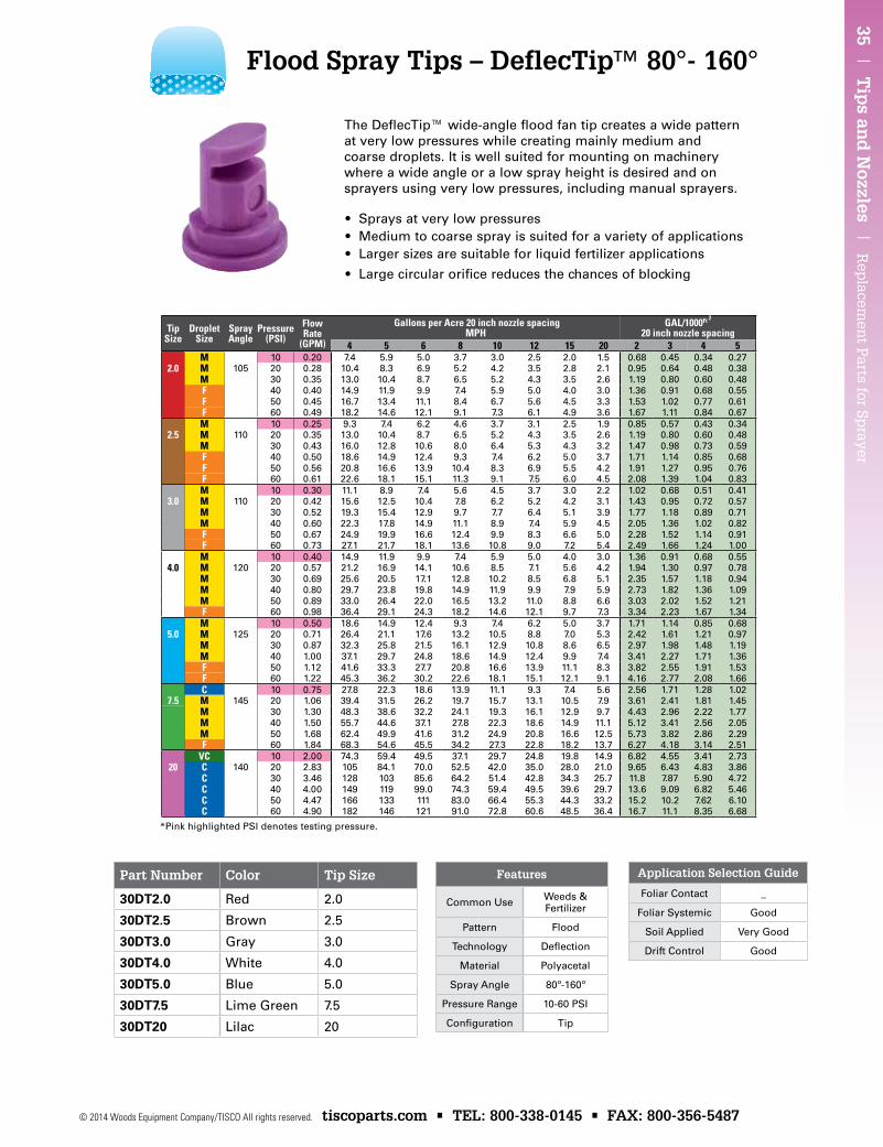
• Sprays at very low pressures• Medium to coarse spray is suited for a variety of applications• Larger sizes are suitable for liquid fertilizer applications
• Large circular orifice reduces the chances of blocking
The DeflecTip™ wide-angle flood fan tip creates a wide pattern at very low pressures while creating mainly medium and coarse droplets. It is well suited for mounting on machinery where a wide angle or a low spray height is desired and on sprayers using very low pressures, including manual sprayers.
Flood Spray Tips – DeflecTip™ 80°- 160°
Application Selection Guide
Foliar Contact _
Foliar Systemic Good
Soil Applied Very Good
Drift Control Good
Features
Common Use Weeds & Fertilizer
Pattern Flood
Technology Deflection
Material Polyacetal
Spray Angle 80º-160º
Pressure Range 10-60 PSI
Configuration Tip
Part Number Color Tip Size
30DT2.0 Red 2.0
30DT2.5 Brown 2.5
30DT3.0 Gray 3.0
30DT4.0 White 4.0
30DT5.0 Blue 5.0
30DT7.5 Lime Green 7.5
30DT20 Lilac 20
Tip Size
DropletSize
Spray Angle
Pressure(PSI)
Flow Rate
(GPM)
Gallons per Acre 20 inch nozzle spacing MPH
GAL/1000Ft 2 20 inch nozzle spacing
4 5 6 8 10 12 15 20 2 3 4 5M 10 0.20 7.4 5.9 5.0 3.7 3.0 2.5 2.0 1.5 0.68 0.45 0.34 0.27
2.0 M 105 20 0.28 10.4 8.3 6.9 5.2 4.2 3.5 2.8 2.1 0.95 0.64 0.48 0.38M 30 0.35 13.0 10.4 8.7 6.5 5.2 4.3 3.5 2.6 1.19 0.80 0.60 0.48F 40 0.40 14.9 11.9 9.9 7.4 5.9 5.0 4.0 3.0 1.36 0.91 0.68 0.55F 50 0.45 16.7 13.4 11.1 8.4 6.7 5.6 4.5 3.3 1.53 1.02 0.77 0.61F 60 0.49 18.2 14.6 12.1 9.1 7.3 6.1 4.9 3.6 1.67 1.11 0.84 0.67M 10 0.25 9.3 7.4 6.2 4.6 3.7 3.1 2.5 1.9 0.85 0.57 0.43 0.34
2.5 M 110 20 0.35 13.0 10.4 8.7 6.5 5.2 4.3 3.5 2.6 1.19 0.80 0.60 0.48M 30 0.43 16.0 12.8 10.6 8.0 6.4 5.3 4.3 3.2 1.47 0.98 0.73 0.59F 40 0.50 18.6 14.9 12.4 9.3 7.4 6.2 5.0 3.7 1.71 1.14 0.85 0.68F 50 0.56 20.8 16.6 13.9 10.4 8.3 6.9 5.5 4.2 1.91 1.27 0.95 0.76F 60 0.61 22.6 18.1 15.1 11.3 9.1 7.5 6.0 4.5 2.08 1.39 1.04 0.83M 10 0.30 11.1 8.9 7.4 5.6 4.5 3.7 3.0 2.2 1.02 0.68 0.51 0.41
3.0 M 110 20 0.42 15.6 12.5 10.4 7.8 6.2 5.2 4.2 3.1 1.43 0.95 0.72 0.57M 30 0.52 19.3 15.4 12.9 9.7 7.7 6.4 5.1 3.9 1.77 1.18 0.89 0.71M 40 0.60 22.3 17.8 14.9 11.1 8.9 7.4 5.9 4.5 2.05 1.36 1.02 0.82F 50 0.67 24.9 19.9 16.6 12.4 9.9 8.3 6.6 5.0 2.28 1.52 1.14 0.91F 60 0.73 27.1 21.7 18.1 13.6 10.8 9.0 7.2 5.4 2.49 1.66 1.24 1.00M 10 0.40 14.9 11.9 9.9 7.4 5.9 5.0 4.0 3.0 1.36 0.91 0.68 0.55
4.0 M 120 20 0.57 21.2 16.9 14.1 10.6 8.5 7.1 5.6 4.2 1.94 1.30 0.97 0.78M 30 0.69 25.6 20.5 17.1 12.8 10.2 8.5 6.8 5.1 2.35 1.57 1.18 0.94M 40 0.80 29.7 23.8 19.8 14.9 11.9 9.9 7.9 5.9 2.73 1.82 1.36 1.09M 50 0.89 33.0 26.4 22.0 16.5 13.2 11.0 8.8 6.6 3.03 2.02 1.52 1.21F 60 0.98 36.4 29.1 24.3 18.2 14.6 12.1 9.7 7.3 3.34 2.23 1.67 1.34M 10 0.50 18.6 14.9 12.4 9.3 7.4 6.2 5.0 3.7 1.71 1.14 0.85 0.68
5.0 M 125 20 0.71 26.4 21.1 17.6 13.2 10.5 8.8 7.0 5.3 2.42 1.61 1.21 0.97M 30 0.87 32.3 25.8 21.5 16.1 12.9 10.8 8.6 6.5 2.97 1.98 1.48 1.19M 40 1.00 37.1 29.7 24.8 18.6 14.9 12.4 9.9 7.4 3.41 2.27 1.71 1.36F 50 1.12 41.6 33.3 27.7 20.8 16.6 13.9 11.1 8.3 3.82 2.55 1.91 1.53F 60 1.22 45.3 36.2 30.2 22.6 18.1 15.1 12.1 9.1 4.16 2.77 2.08 1.66C 10 0.75 27.8 22.3 18.6 13.9 11.1 9.3 7.4 5.6 2.56 1.71 1.28 1.02
7.5 M 145 20 1.06 39.4 31.5 26.2 19.7 15.7 13.1 10.5 7.9 3.61 2.41 1.81 1.45M 30 1.30 48.3 38.6 32.2 24.1 19.3 16.1 12.9 9.7 4.43 2.96 2.22 1.77M 40 1.50 55.7 44.6 37.1 27.8 22.3 18.6 14.9 11.1 5.12 3.41 2.56 2.05M 50 1.68 62.4 49.9 41.6 31.2 24.9 20.8 16.6 12.5 5.73 3.82 2.86 2.29F 60 1.84 68.3 54.6 45.5 34.2 27.3 22.8 18.2 13.7 6.27 4.18 3.14 2.51
VC 10 2.00 74.3 59.4 49.5 37.1 29.7 24.8 19.8 14.9 6.82 4.55 3.41 2.7320 C 140 20 2.83 105 84.1 70.0 52.5 42.0 35.0 28.0 21.0 9.65 6.43 4.83 3.86
C 30 3.46 128 103 85.6 64.2 51.4 42.8 34.3 25.7 11.8 7.87 5.90 4.72C 40 4.00 149 119 99.0 74.3 59.4 49.5 39.6 29.7 13.6 9.09 6.82 5.46C 50 4.47 166 133 111 83.0 66.4 55.3 44.3 33.2 15.2 10.2 7.62 6.10C 60 4.90 182 146 121 91.0 72.8 60.6 48.5 36.4 16.7 11.1 8.35 6.68
*Pink highlighted PSI denotes testing pressure.
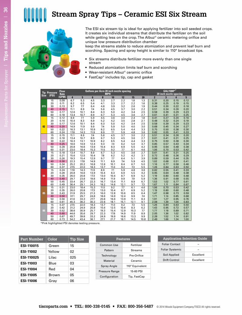
Rep
lace
men
t P
arts
for
Sp
raye
r |
Tip
s an
d N
ozzl
es |
36
tiscoparts.com • TEL: 800-338-0145 • FAX: 800-356-5487 © 2014 Woods Equipment Company/TISCO All rights reserved.
Part Number Color Tip Size
ESI-110015 Green 15
ESI-11002 Yellow 02
ESI-110025 Lilac 025
ESI-11003 Blue 03
ESI-11004 Red 04
ESI-11005 Brown 05
ESI-11006 Gray 06
TipSize
Pressure(PSI)
Flow Rate
(GPM)
Gallons per Acre 20 inch nozzle spacing MPH
GAL/1000Ft 2 20 inch nozzle spacing
4 5 6 8 10 12 15 20 2 3 4 515 0.09 6.7 5.3 4.5 3.3 2.7 2.2 1.8 1.3 0.31 0.20 0.15 0.1220 0.11 8.2 6.5 5.4 4.1 3.3 2.7 2.2 1.6 0.38 0.25 0.19 0.15
015 30 0.13 9.7 7.7 6.4 4.8 3.9 3.2 2.6 1.9 0.44 0.30 0.22 0.1840 0.15 11.1 8.9 7.4 5.6 4.5 3.7 3.0 2.2 0.51 0.34 0.26 0.2050 0.17 12.6 10.1 8.4 6.3 5.0 4.2 3.4 2.5 0.58 0.39 0.29 0.2360 0.18 13.4 10.7 8.9 6.7 5.3 4.5 3.6 2.7 0.61 0.41 0.31 0.2515 0.12 8.9 7.1 5.9 4.5 3.6 3.0 2.4 1.8 0.41 0.27 0.20 0.1620 0.14 10.4 8.3 6.9 5.2 4.2 3.5 2.8 2.1 0.48 0.32 0.24 0.1930 0.17 12.6 10.1 8.4 6.3 5.0 4.2 3.4 2.5 0.58 0.39 0.29 0.23
02 40 0.20 14.9 11.9 9.9 7.4 5.9 5.0 4.0 3.0 0.68 0.45 0.34 0.2750 0.22 16.3 13.1 10.9 8.2 6.5 5.4 4.4 3.3 0.75 0.50 0.38 0.3060 0.24 17.8 14.3 11.9 8.9 7.1 5.9 4.8 3.6 0.82 0.55 0.41 0.3315 0.15 11.1 8.9 7.4 5.6 4.5 3.7 3.0 2.2 0.51 0.34 0.26 0.2020 0.18 13.4 10.7 8.9 6.7 5.3 4.5 3.6 2.7 0.61 0.41 0.31 0.25
025 30 0.22 16.3 13.1 10.9 8.2 6.5 5.4 4.4 3.3 0.75 0.50 0.38 0.3040 0.25 18.6 14.9 12.4 9.3 7.4 6.2 5.0 3.7 0.85 0.57 0.43 0.3450 0.28 20.8 16.6 13.9 10.4 8.3 6.9 5.5 4.2 0.95 0.64 0.48 0.3860 0.31 23.0 18.4 15.3 11.5 9.2 7.7 6.1 4.6 1.06 0.70 0.53 0.4215 0.18 13.4 10.7 8.9 6.7 5.3 4.5 3.6 2.7 0.61 0.41 0.31 0.2520 0.21 15.6 12.5 10.4 7.8 6.2 5.2 4.2 3.1 0.72 0.48 0.36 0.29
03 30 0.26 19.3 15.4 12.9 9.7 7.7 6.4 5.1 3.9 0.89 0.59 0.44 0.3540 0.30 22.3 17.8 14.9 11.1 8.9 7.4 5.9 4.5 1.02 0.68 0.51 0.4150 0.34 25.2 20.2 16.8 12.6 10.1 8.4 6.7 5.0 1.16 0.77 0.58 0.4660 0.37 27.5 22.0 18.3 13.7 11.0 9.2 7.3 5.5 1.26 0.84 0.63 0.5015 0.24 17.8 14.3 11.9 8.9 7.1 5.9 4.8 3.6 0.82 0.55 0.41 0.3320 0.28 20.8 16.6 13.9 10.4 8.3 6.9 5.5 4.2 0.95 0.64 0.48 0.38
04 30 0.35 26.0 20.8 17.3 13.0 10.4 8.7 6.9 5.2 1.19 0.80 0.60 0.4840 0.40 29.7 23.8 19.8 14.9 11.9 9.9 7.9 5.9 1.36 0.91 0.68 0.5550 0.45 33.4 26.7 22.3 16.7 13.4 11.1 8.9 6.7 1.53 1.02 0.77 0.6160 0.49 36.4 29.1 24.3 18.2 14.6 12.1 9.7 7.3 1.67 1.11 0.84 0.6715 0.31 23.0 18.4 15.3 11.5 9.2 7.7 6.1 4.6 1.06 0.70 0.53 0.4220 0.35 26.0 20.8 17.3 13.0 10.4 8.7 6.9 5.2 1.19 0.80 0.60 0.48
05 30 0.43 31.9 25.5 21.3 16.0 12.8 10.6 8.5 6.4 1.47 0.98 0.73 0.5940 0.50 37.1 29.7 24.8 18.6 14.9 12.4 9.9 7.4 1.71 1.14 0.85 0.6850 0.56 41.6 33.3 27.7 20.8 16.6 13.9 11.1 8.3 1.91 1.27 0.95 0.7660 0.61 45.3 36.2 30.2 22.6 18.1 15.1 12.1 9.1 2.08 1.39 1.04 0.8315 0.37 27.5 22.0 18.3 13.7 11.0 9.2 7.3 5.5 1.26 0.84 0.63 0.5020 0.42 31.2 24.9 20.8 15.6 12.5 10.4 8.3 6.2 1.43 0.95 0.72 0.57
06 30 0.52 38.6 30.9 25.7 19.3 15.4 12.9 10.3 7.7 1.77 1.18 0.89 0.7140 0.60 44.6 35.6 29.7 22.3 17.8 14.9 11.9 8.9 2.05 1.36 1.02 0.8250 0.67 49.7 39.8 33.2 24.9 19.9 16.6 13.3 9.9 2.28 1.52 1.14 0.9160 0.73 54.2 43.4 36.1 27.1 21.7 18.1 14.5 10.8 2.49 1.66 1.24 1.00
*Pink highlighted PSI denotes testing pressure.
• Six streams distribute fertilizer more evenly than one single stream
• Reduced atomization limits leaf burn and scorching• Wear-resistant Albuz® ceramic orifice• FastCap® includes tip, cap and gasket
The ESI six stream tip is ideal for applying fertilizer into soil seeded crops. It creates six individual streams that distribute the fertilizer on the soil while getting less on the crop. The Albuz® ceramic metering orifice and unique low pressure distribution chamber keep the streams stable to reduce atomization and prevent leaf burn and scorching. Spacing and spray height is similar to 110° broadcast tips.
Stream Spray Tips – Ceramic ESI Six Stream
Application Selection Guide
Foliar Contact –
Foliar Systemic –
Soil Applied Excellent
Drift Control Excellent
Features
Common Use Fertilizer
Pattern Streams
Technology Pre-Orifice
Material Ceramic
Spray Angle 110º Equivalent
Pressure Range 15-60 PSI
Configuration Tip, FastCap
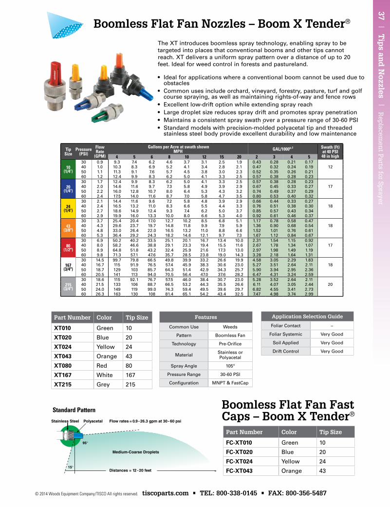
37 | T
ips an
d N
ozzles | R
eplacem
ent P
arts for Sprayer
© 2014 Woods Equipment Company/TISCO All rights reserved. tiscoparts.com • TEL: 800-338-0145 • FAX: 800-356-5487
Boomless Flat Fan Fast Caps – Boom X Tender®
Part Number Color Tip Size
XT010 Green 10
XT020 Blue 20
XT024 Yellow 24
XT043 Orange 43
XT080 Red 80
XT167 White 167
XT215 Grey 215
TipSize
Pressure(PSI)
Flow Rate
(GPM)
Gallons per Acre at swath shown MPH GAL/1000Ft 2 Swath (Ft)
at 40 PSI48 in high4 5 6 8 10 12 15 20 2 3 4 5
10(1/4')
30 0.9 9.3 7.4 6.2 4.6 3.7 3.1 2.5 1.9 0.43 0.28 0.21 0.1740 1.0 10.3 8.3 6.9 5.2 4.1 3.4 2.8 2.1 0.47 0.32 0.24 0.19 1250 1.1 11.3 9.1 7.6 5.7 4.5 3.8 3.0 2.3 0.52 0.35 0.26 0.2160 1.2 12.4 9.9 8.3 6.2 5.0 4.1 3.3 2.5 0.57 0.38 0.28 0.23
20(1/4')
30 1.7 12.4 9.9 8.3 6.2 5.0 4.1 3.3 2.5 0.57 0.38 0.28 0.2340 2.0 14.6 11.6 9.7 7.3 5.8 4.9 3.9 2.9 0.67 0.45 0.33 0.27 1750 2.2 16.0 12.8 10.7 8.0 6.4 5.3 4.3 3.2 0.74 0.49 0.37 0.2960 2.4 17.5 14.0 11.6 8.7 7.0 5.8 4.7 3.5 0.80 0.53 0.40 0.32
24(1/4')
30 2.1 14.4 11.6 9.6 7.2 5.8 4.8 3.9 2.9 0.66 0.44 0.33 0.2740 2.4 16.5 13.2 11.0 8.3 6.6 5.5 4.4 3.3 0.76 0.51 0.38 0.30 1850 2.7 18.6 14.9 12.4 9.3 7.4 6.2 5.0 3.7 0.85 0.57 0.43 0.3460 2.9 19.9 16.0 13.3 10.0 8.0 6.6 5.3 4.0 0.92 0.61 0.46 0.37
43(3/8")
30 3.7 25.4 20.4 17.0 12.7 10.2 8.5 6.8 5.1 1.17 0.78 0.58 0.4740 4.3 29.6 23.7 19.7 14.8 11.8 9.9 7.9 5.9 1.36 0.90 0.68 0.54 1850 4.8 33.0 26.4 22.0 16.5 13.2 11.0 8.8 6.6 1.52 1.01 0.76 0.6160 5.3 36.4 29.2 24.3 18.2 14.6 12.1 9.7 7.3 1.67 1.12 0.84 0.67
80(1/2")
30 6.9 50.2 40.2 33.5 25.1 20.1 16.7 13.4 10.0 2.31 1.54 1.15 0.9240 8.0 58.2 46.6 38.8 29.1 23.3 19.4 15.5 11.6 2.67 1.78 1.34 1.07 1750 8.9 64.8 51.8 43.2 32.4 25.9 21.6 17.3 13.0 2.97 1.98 1.49 1.1960 9.8 71.3 57.1 47.6 35.7 28.5 23.8 19.0 14.3 3.28 2.18 1.64 1.31
167(3/4")
30 14.5 99.7 79.8 66.5 49.8 39.9 33.2 26.6 19.9 4.58 3.05 2.29 1.8340 16.7 115 91.9 76.5 57.4 45.9 38.3 30.6 23.0 5.27 3.51 2.64 2.11 1850 18.7 129 103 85.7 64.3 51.4 42.9 34.3 25.7 5.90 3.94 2.95 2.3660 20.5 141 113 94.0 70.5 56.4 47.0 37.6 28.2 6.47 4.31 3.24 2.59
215(3/4")
30 18.6 115 92.1 76.7 57.5 46.0 38.4 30.7 23.0 5.28 3.52 2.64 2.1140 21.5 133 106 88.7 66.5 53.2 44.3 35.5 26.6 6.11 4.07 3.05 2.44 2050 24.0 149 119 99.0 74.3 59.4 49.5 39.6 29.7 6.82 4.55 3.41 2.7360 26.3 163 130 108 81.4 65.1 54.2 43.4 32.5 7.47 4.98 3.74 2.99
Part Number Color Tip Size
FC-XT010 Green 10
FC-XT020 Blue 20
FC-XT024 Yellow 24
FC-XT043 Orange 43
Boomless Flat Fan Nozzles – Boom X Tender®
• Ideal for applications where a conventional boom cannot be used due to obstacles
• Common uses include orchard, vineyard, forestry, pasture, turf and golf course spraying, as well as maintaining rights-of-way and fence rows
• Excellent low-drift option while extending spray reach• Large droplet size reduces spray drift and promotes spray penetration• Maintains a consistent spray swath over a pressure range of 30-60 PSI• Standard models with precision-molded polyacetal tip and threaded
stainless steel body provide excellent durability and low maintenance
The XT introduces boomless spray technology, enabling spray to be targeted into places that conventional booms and other tips cannot reach. XT delivers a uniform spray pattern over a distance of up to 20 feet. Ideal for weed control in forests and pastureland.
Application Selection Guide
Foliar Contact –
Foliar Systemic Very Good
Soil Applied Very Good
Drift Control Very Good
Features
Common Use Weeds
Pattern Boomless Fan
Technology Pre-Orifice
Material Stainless or Polyacetal
Spray Angle 105º
Pressure Range 30-60 PSI
Configuration MNPT & FastCap
Standard Pattern
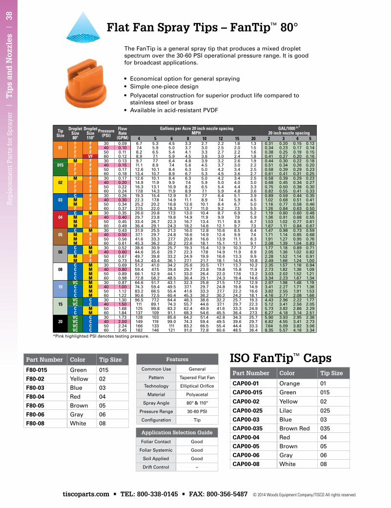
Rep
lace
men
t P
arts
for
Sp
raye
r |
Tip
s an
d N
ozzl
es |
38
tiscoparts.com • TEL: 800-338-0145 • FAX: 800-356-5487 © 2014 Woods Equipment Company/TISCO All rights reserved.
*Pink highlighted PSI denotes testing pressure.
ISO FanTip™ CapsPart Number Color Tip Size
CAP00-01 Orange 01
CAP00-015 Green 015
CAP00-02 Yellow 02
CAP00-025 Lilac 025
CAP00-03 Blue 03
CAP00-035 Brown Red 035
CAP00-04 Red 04
CAP00-05 Brown 05
CAP00-06 Gray 06
CAP00-08 White 08
Part Number Color Tip Size
F80-015 Green 015
F80-02 Yellow 02
F80-03 Blue 03
F80-04 Red 04
F80-05 Brown 05
F80-06 Gray 06
F80-08 White 08
TipSize
DropletSize80º
DropletSize110º
Pressure(PSI)
Flow Rate
(GPM)
Gallons per Acre 20 inch nozzle spacing MPH
GAL/1000 Ft 2 20 inch nozzle spacing
4 5 6 8 10 12 15 20 2 3 4 5F F 30 0.09 6.7 5.3 4.5 3.3 2.7 2.2 1.8 1.3 0.31 0.20 0.15 0.12
01 F F 40 0.10 7.4 5.9 5.0 3.7 3.0 2.5 2.0 1.5 0.34 0.23 0.17 0.14F F 50 0.11 8.2 6.5 5.4 4.1 3.3 2.7 2.2 1.6 0.38 0.25 0.19 0.15F VF 60 0.12 8.9 7.1 5.9 4.5 3.6 3.0 2.4 1.8 0.41 0.27 0.20 0.16M F 30 0.13 9.7 7.7 6.4 4.8 3.9 3.2 2.6 1.9 0.44 0.30 0.22 0.18
015 F F 40 0.15 11.1 8.9 7.4 5.6 4.5 3.7 3.0 2.2 0.51 0.34 0.26 0.20F F 50 0.17 12.6 10.1 8.4 6.3 5.0 4.2 3.4 2.5 0.58 0.39 0.29 0.23F F 60 0.18 13.4 10.7 8.9 6.7 5.3 4.5 3.6 2.7 0.61 0.41 0.31 0.25M F 30 0.17 12.6 10.1 8.4 6.3 5.0 4.2 3.4 2.5 0.58 0.39 0.29 0.23
02 F F 40 0.20 14.9 11.9 9.9 7.4 5.9 5.0 4.0 3.0 0.68 0.45 0.34 0.27F F 50 0.22 16.3 13.1 10.9 8.2 6.5 5.4 4.4 3.3 0.75 0.50 0.38 0.30F F 60 0.24 17.8 14.3 11.9 8.9 7.1 5.9 4.8 3.6 0.82 0.55 0.41 0.33C F 30 0.26 19.3 15.4 12.9 9.7 7.7 6.4 5.1 3.9 0.89 0.59 0.44 0.35
03 M F 40 0.30 22.3 17.8 14.9 11.1 8.9 7.4 5.9 4.5 1.02 0.68 0.51 0.41M F 50 0.34 25.2 20.2 16.8 12.6 10.1 8.4 6.7 5.0 1.16 0.77 0.58 0.46F F 60 0.37 27.5 22.0 18.3 13.7 11.0 9.2 7.3 5.5 1.26 0.84 0.63 0.50C M 30 0.35 26.0 20.8 17.3 13.0 10.4 8.7 6.9 5.2 1.19 0.80 0.60 0.48
04 M F 40 0.40 29.7 23.8 19.8 14.9 11.9 9.9 7.9 5.9 1.36 0.91 0.68 0.55M F 50 0.45 33.4 26.7 22.3 16.7 13.4 11.1 8.9 6.7 1.53 1.02 0.77 0.61M F 60 0.49 36.4 29.1 24.3 18.2 14.6 12.1 9.7 7.3 1.67 1.11 0.84 0.67C M 30 0.43 31.9 25.5 21.3 16.0 12.8 10.6 8.5 6.4 1.47 0.98 0.73 0.59
05 M F 40 0.50 37.1 29.7 24.8 18.6 14.9 12.4 9.9 7.4 1.71 1.14 0.85 0.68M F 50 0.56 41.6 33.3 27.7 20.8 16.6 13.9 11.1 8.3 1.91 1.27 0.95 0.76M F 60 0.61 45.3 36.2 30.2 22.6 18.1 15.1 12.1 9.1 2.08 1.39 1.04 0.83C M 30 0.52 38.6 30.9 25.7 19.3 15.4 12.9 10.3 7.7 1.77 1.18 0.89 0.71
06 C M 40 0.60 44.6 35.6 29.7 22.3 17.8 14.9 11.9 8.9 2.05 1.36 1.02 0.82M F 50 0.67 49.7 39.8 33.2 24.9 19.9 16.6 13.3 9.9 2.28 1.52 1.14 0.91M F 60 0.73 54.2 43.4 36.1 27.1 21.7 18.1 14.5 10.8 2.49 1.66 1.24 1.00C M 30 0.69 51.2 41.0 34.2 25.6 20.5 17.1 13.7 10.2 2.35 1.57 1.18 0.94
08 C M 40 0.80 59.4 47.5 39.6 29.7 23.8 19.8 15.8 11.9 2.73 1.82 1.36 1.09C M 50 0.89 66.1 52.9 44.1 33.0 26.4 22.0 17.6 13.2 3.03 2.02 1.52 1.21C M 60 0.98 72.8 58.2 48.5 36.4 29.1 24.3 19.4 14.6 3.34 2.23 1.67 1.34
VC M 30 0.87 64.6 51.7 43.1 32.3 25.8 21.5 17.2 12.9 2.97 1.98 1.48 1.1910 C M 40 1.00 74.3 59.4 49.5 37.1 29.7 24.8 19.8 14.9 3.41 2.27 1.71 1.36
C M 50 1.12 83.2 66.5 55.4 41.6 33.3 27.7 22.2 16.6 3.82 2.55 1.91 1.53C M 60 1.22 90.6 72.5 60.4 45.3 36.2 30.2 24.2 18.1 4.16 2.77 2.08 1.66
VC C 30 1.30 96.5 77.2 64.4 48.3 38.6 32.2 25.7 19.3 4.43 2.96 2.22 1.7715 VC C 40 1.50 111 89.1 74.3 55.7 44.6 37.1 29.7 22.3 5.12 3.41 2.56 2.05
C M 50 1.68 125 99.8 83.2 62.4 49.9 41.6 33.3 24.9 5.73 3.82 2.86 2.29C M 60 1.84 137 109 91.1 68.3 54.6 45.5 36.4 27.3 6.27 4.18 3.14 2.51
VC C 30 1.73 128 103 85.6 64.2 51.4 42.8 34.3 25.7 5.90 3.93 2.95 2.3620 VC C 40 2.00 149 119 99.0 74.3 59.4 49.5 39.6 29.7 6.82 4.55 3.41 2.73
VC C 50 2.24 166 133 111 83.2 66.5 55.4 44.4 33.3 7.64 5.09 3.82 3.06VC C 60 2.45 182 146 121 91.0 72.8 60.6 48.5 36.4 8.35 5.57 4.18 3.34
Flat Fan Spray Tips – FanTip™ 80°
• Economical option for general spraying• Simple one-piece design
• Polyacetal construction for superior product life compared to stainless steel or brass
• Available in acid-resistant PVDF
The FanTip is a general spray tip that produces a mixed droplet spectrum over the 30-60 PSI operational pressure range. It is good for broadcast applications.
Application Selection Guide
Foliar Contact Good
Foliar Systemic Good
Soil Applied Good
Drift Control –
Features
Common Use General
Pattern Tapered Flat Fan
Technology EllipticalOrifice
Material Polyacetal
Spray Angle 80º & 110º
Pressure Range 30-60 PSI
Configuration Tip
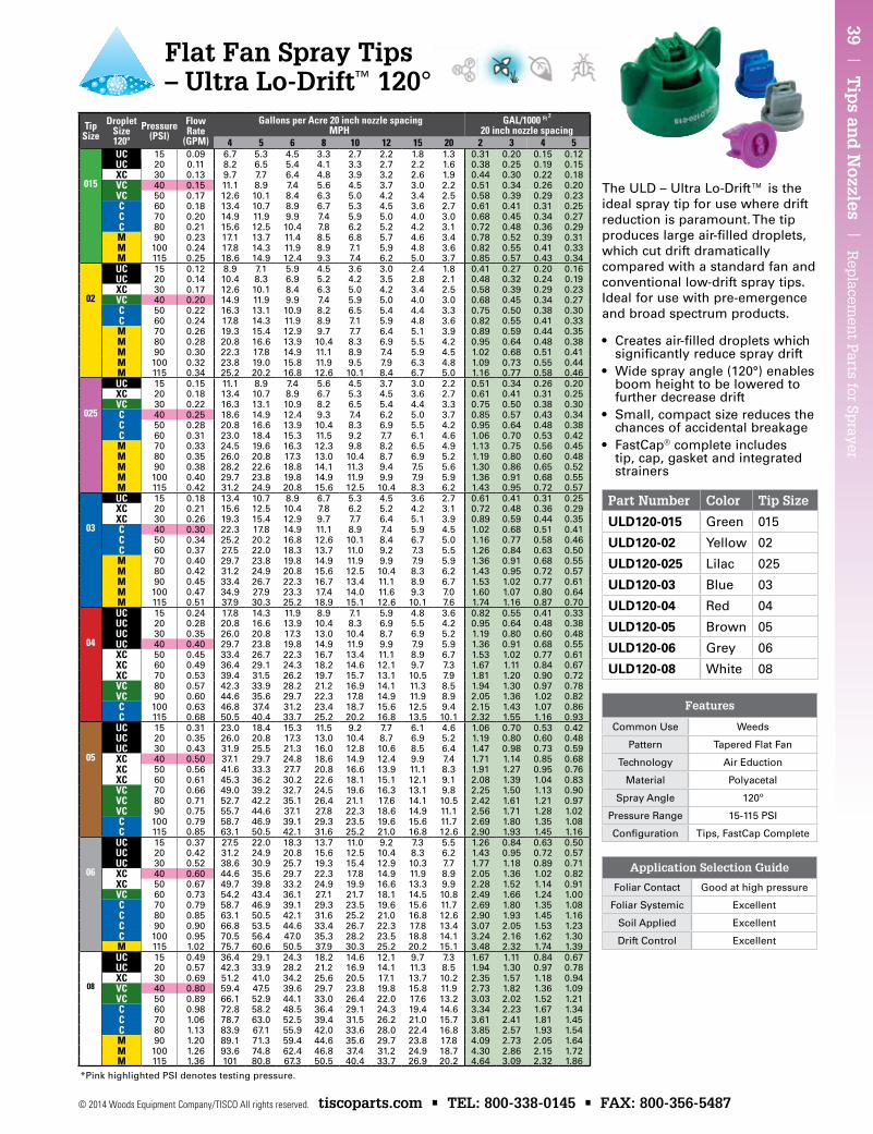
39 | T
ips an
d N
ozzles | R
eplacem
ent P
arts for Sprayer
© 2014 Woods Equipment Company/TISCO All rights reserved. tiscoparts.com • TEL: 800-338-0145 • FAX: 800-356-5487
Part Number Color Tip Size
uLD120-015 Green 015
uLD120-02 Yellow 02
uLD120-025 Lilac 025
uLD120-03 Blue 03
uLD120-04 Red 04
uLD120-05 Brown 05
uLD120-06 Grey 06
uLD120-08 White 08
TipSize
DropletSize120º
Pressure(PSI)
Flow Rate
(GPM)
Gallons per Acre 20 inch nozzle spacing MPH
GAL/1000 Ft 2 20 inch nozzle spacing
4 5 6 8 10 12 15 20 2 3 4 5UC 15 0.09 6.7 5.3 4.5 3.3 2.7 2.2 1.8 1.3 0.31 0.20 0.15 0.12UC 20 0.11 8.2 6.5 5.4 4.1 3.3 2.7 2.2 1.6 0.38 0.25 0.19 0.15XC 30 0.13 9.7 7.7 6.4 4.8 3.9 3.2 2.6 1.9 0.44 0.30 0.22 0.18
015 VC 40 0.15 11.1 8.9 7.4 5.6 4.5 3.7 3.0 2.2 0.51 0.34 0.26 0.20VC 50 0.17 12.6 10.1 8.4 6.3 5.0 4.2 3.4 2.5 0.58 0.39 0.29 0.23C 60 0.18 13.4 10.7 8.9 6.7 5.3 4.5 3.6 2.7 0.61 0.41 0.31 0.25C 70 0.20 14.9 11.9 9.9 7.4 5.9 5.0 4.0 3.0 0.68 0.45 0.34 0.27C 80 0.21 15.6 12.5 10.4 7.8 6.2 5.2 4.2 3.1 0.72 0.48 0.36 0.29M 90 0.23 17.1 13.7 11.4 8.5 6.8 5.7 4.6 3.4 0.78 0.52 0.39 0.31M 100 0.24 17.8 14.3 11.9 8.9 7.1 5.9 4.8 3.6 0.82 0.55 0.41 0.33M 115 0.25 18.6 14.9 12.4 9.3 7.4 6.2 5.0 3.7 0.85 0.57 0.43 0.34UC 15 0.12 8.9 7.1 5.9 4.5 3.6 3.0 2.4 1.8 0.41 0.27 0.20 0.16UC 20 0.14 10.4 8.3 6.9 5.2 4.2 3.5 2.8 2.1 0.48 0.32 0.24 0.19XC 30 0.17 12.6 10.1 8.4 6.3 5.0 4.2 3.4 2.5 0.58 0.39 0.29 0.23
02 VC 40 0.20 14.9 11.9 9.9 7.4 5.9 5.0 4.0 3.0 0.68 0.45 0.34 0.27C 50 0.22 16.3 13.1 10.9 8.2 6.5 5.4 4.4 3.3 0.75 0.50 0.38 0.30C 60 0.24 17.8 14.3 11.9 8.9 7.1 5.9 4.8 3.6 0.82 0.55 0.41 0.33M 70 0.26 19.3 15.4 12.9 9.7 7.7 6.4 5.1 3.9 0.89 0.59 0.44 0.35M 80 0.28 20.8 16.6 13.9 10.4 8.3 6.9 5.5 4.2 0.95 0.64 0.48 0.38M 90 0.30 22.3 17.8 14.9 11.1 8.9 7.4 5.9 4.5 1.02 0.68 0.51 0.41M 100 0.32 23.8 19.0 15.8 11.9 9.5 7.9 6.3 4.8 1.09 0.73 0.55 0.44M 115 0.34 25.2 20.2 16.8 12.6 10.1 8.4 6.7 5.0 1.16 0.77 0.58 0.46UC 15 0.15 11.1 8.9 7.4 5.6 4.5 3.7 3.0 2.2 0.51 0.34 0.26 0.20XC 20 0.18 13.4 10.7 8.9 6.7 5.3 4.5 3.6 2.7 0.61 0.41 0.31 0.25VC 30 0.22 16.3 13.1 10.9 8.2 6.5 5.4 4.4 3.3 0.75 0.50 0.38 0.30
025 C 40 0.25 18.6 14.9 12.4 9.3 7.4 6.2 5.0 3.7 0.85 0.57 0.43 0.34C 50 0.28 20.8 16.6 13.9 10.4 8.3 6.9 5.5 4.2 0.95 0.64 0.48 0.38C 60 0.31 23.0 18.4 15.3 11.5 9.2 7.7 6.1 4.6 1.06 0.70 0.53 0.42M 70 0.33 24.5 19.6 16.3 12.3 9.8 8.2 6.5 4.9 1.13 0.75 0.56 0.45M 80 0.35 26.0 20.8 17.3 13.0 10.4 8.7 6.9 5.2 1.19 0.80 0.60 0.48M 90 0.38 28.2 22.6 18.8 14.1 11.3 9.4 7.5 5.6 1.30 0.86 0.65 0.52M 100 0.40 29.7 23.8 19.8 14.9 11.9 9.9 7.9 5.9 1.36 0.91 0.68 0.55M 115 0.42 31.2 24.9 20.8 15.6 12.5 10.4 8.3 6.2 1.43 0.95 0.72 0.57UC 15 0.18 13.4 10.7 8.9 6.7 5.3 4.5 3.6 2.7 0.61 0.41 0.31 0.25XC 20 0.21 15.6 12.5 10.4 7.8 6.2 5.2 4.2 3.1 0.72 0.48 0.36 0.29XC 30 0.26 19.3 15.4 12.9 9.7 7.7 6.4 5.1 3.9 0.89 0.59 0.44 0.35
03 C 40 0.30 22.3 17.8 14.9 11.1 8.9 7.4 5.9 4.5 1.02 0.68 0.51 0.41C 50 0.34 25.2 20.2 16.8 12.6 10.1 8.4 6.7 5.0 1.16 0.77 0.58 0.46C 60 0.37 27.5 22.0 18.3 13.7 11.0 9.2 7.3 5.5 1.26 0.84 0.63 0.50M 70 0.40 29.7 23.8 19.8 14.9 11.9 9.9 7.9 5.9 1.36 0.91 0.68 0.55M 80 0.42 31.2 24.9 20.8 15.6 12.5 10.4 8.3 6.2 1.43 0.95 0.72 0.57M 90 0.45 33.4 26.7 22.3 16.7 13.4 11.1 8.9 6.7 1.53 1.02 0.77 0.61M 100 0.47 34.9 27.9 23.3 17.4 14.0 11.6 9.3 7.0 1.60 1.07 0.80 0.64M 115 0.51 37.9 30.3 25.2 18.9 15.1 12.6 10.1 7.6 1.74 1.16 0.87 0.70UC 15 0.24 17.8 14.3 11.9 8.9 7.1 5.9 4.8 3.6 0.82 0.55 0.41 0.33UC 20 0.28 20.8 16.6 13.9 10.4 8.3 6.9 5.5 4.2 0.95 0.64 0.48 0.38UC 30 0.35 26.0 20.8 17.3 13.0 10.4 8.7 6.9 5.2 1.19 0.80 0.60 0.48
04 UC 40 0.40 29.7 23.8 19.8 14.9 11.9 9.9 7.9 5.9 1.36 0.91 0.68 0.55XC 50 0.45 33.4 26.7 22.3 16.7 13.4 11.1 8.9 6.7 1.53 1.02 0.77 0.61XC 60 0.49 36.4 29.1 24.3 18.2 14.6 12.1 9.7 7.3 1.67 1.11 0.84 0.67XC 70 0.53 39.4 31.5 26.2 19.7 15.7 13.1 10.5 7.9 1.81 1.20 0.90 0.72VC 80 0.57 42.3 33.9 28.2 21.2 16.9 14.1 11.3 8.5 1.94 1.30 0.97 0.78VC 90 0.60 44.6 35.6 29.7 22.3 17.8 14.9 11.9 8.9 2.05 1.36 1.02 0.82C 100 0.63 46.8 37.4 31.2 23.4 18.7 15.6 12.5 9.4 2.15 1.43 1.07 0.86C 115 0.68 50.5 40.4 33.7 25.2 20.2 16.8 13.5 10.1 2.32 1.55 1.16 0.93
UC 15 0.31 23.0 18.4 15.3 11.5 9.2 7.7 6.1 4.6 1.06 0.70 0.53 0.42UC 20 0.35 26.0 20.8 17.3 13.0 10.4 8.7 6.9 5.2 1.19 0.80 0.60 0.48UC 30 0.43 31.9 25.5 21.3 16.0 12.8 10.6 8.5 6.4 1.47 0.98 0.73 0.59
05 XC 40 0.50 37.1 29.7 24.8 18.6 14.9 12.4 9.9 7.4 1.71 1.14 0.85 0.68XC 50 0.56 41.6 33.3 27.7 20.8 16.6 13.9 11.1 8.3 1.91 1.27 0.95 0.76XC 60 0.61 45.3 36.2 30.2 22.6 18.1 15.1 12.1 9.1 2.08 1.39 1.04 0.83VC 70 0.66 49.0 39.2 32.7 24.5 19.6 16.3 13.1 9.8 2.25 1.50 1.13 0.90VC 80 0.71 52.7 42.2 35.1 26.4 21.1 17.6 14.1 10.5 2.42 1.61 1.21 0.97VC 90 0.75 55.7 44.6 37.1 27.8 22.3 18.6 14.9 11.1 2.56 1.71 1.28 1.02C 100 0.79 58.7 46.9 39.1 29.3 23.5 19.6 15.6 11.7 2.69 1.80 1.35 1.08C 115 0.85 63.1 50.5 42.1 31.6 25.2 21.0 16.8 12.6 2.90 1.93 1.45 1.16
UC 15 0.37 27.5 22.0 18.3 13.7 11.0 9.2 7.3 5.5 1.26 0.84 0.63 0.50UC 20 0.42 31.2 24.9 20.8 15.6 12.5 10.4 8.3 6.2 1.43 0.95 0.72 0.57UC 30 0.52 38.6 30.9 25.7 19.3 15.4 12.9 10.3 7.7 1.77 1.18 0.89 0.71
06 XC 40 0.60 44.6 35.6 29.7 22.3 17.8 14.9 11.9 8.9 2.05 1.36 1.02 0.82XC 50 0.67 49.7 39.8 33.2 24.9 19.9 16.6 13.3 9.9 2.28 1.52 1.14 0.91VC 60 0.73 54.2 43.4 36.1 27.1 21.7 18.1 14.5 10.8 2.49 1.66 1.24 1.00C 70 0.79 58.7 46.9 39.1 29.3 23.5 19.6 15.6 11.7 2.69 1.80 1.35 1.08C 80 0.85 63.1 50.5 42.1 31.6 25.2 21.0 16.8 12.6 2.90 1.93 1.45 1.16C 90 0.90 66.8 53.5 44.6 33.4 26.7 22.3 17.8 13.4 3.07 2.05 1.53 1.23C 100 0.95 70.5 56.4 47.0 35.3 28.2 23.5 18.8 14.1 3.24 2.16 1.62 1.30M 115 1.02 75.7 60.6 50.5 37.9 30.3 25.2 20.2 15.1 3.48 2.32 1.74 1.39UC 15 0.49 36.4 29.1 24.3 18.2 14.6 12.1 9.7 7.3 1.67 1.11 0.84 0.67UC 20 0.57 42.3 33.9 28.2 21.2 16.9 14.1 11.3 8.5 1.94 1.30 0.97 0.78XC 30 0.69 51.2 41.0 34.2 25.6 20.5 17.1 13.7 10.2 2.35 1.57 1.18 0.94
08 VC 40 0.80 59.4 47.5 39.6 29.7 23.8 19.8 15.8 11.9 2.73 1.82 1.36 1.09VC 50 0.89 66.1 52.9 44.1 33.0 26.4 22.0 17.6 13.2 3.03 2.02 1.52 1.21C 60 0.98 72.8 58.2 48.5 36.4 29.1 24.3 19.4 14.6 3.34 2.23 1.67 1.34C 70 1.06 78.7 63.0 52.5 39.4 31.5 26.2 21.0 15.7 3.61 2.41 1.81 1.45C 80 1.13 83.9 67.1 55.9 42.0 33.6 28.0 22.4 16.8 3.85 2.57 1.93 1.54M 90 1.20 89.1 71.3 59.4 44.6 35.6 29.7 23.8 17.8 4.09 2.73 2.05 1.64M 100 1.26 93.6 74.8 62.4 46.8 37.4 31.2 24.9 18.7 4.30 2.86 2.15 1.72M 115 1.36 101 80.8 67.3 50.5 40.4 33.7 26.9 20.2 4.64 3.09 2.32 1.86
The ULD – Ultra Lo-Drift™ is the ideal spray tip for use where drift reduction is paramount. The tip produces large air-filled droplets, which cut drift dramatically compared with a standard fan and conventional low-drift spray tips. Ideal for use with pre-emergence and broad spectrum products.
• Creates air-filled droplets which significantly reduce spray drift
• Wide spray angle (120°) enables boom height to be lowered to further decrease drift
• Small, compact size reduces the chances of accidental breakage
• FastCap® complete includes tip, cap, gasket and integrated strainers
*Pink highlighted PSI denotes testing pressure.
Application Selection Guide
Foliar Contact Good at high pressure
Foliar Systemic Excellent
Soil Applied Excellent
Drift Control Excellent
Features
Common Use Weeds
Pattern Tapered Flat Fan
Technology Air Eduction
Material Polyacetal
Spray Angle 120º
Pressure Range 15-115 PSI
Configuration Tips, FastCap Complete
Flat Fan Spray Tips – Ultra Lo-Drift™ 120°
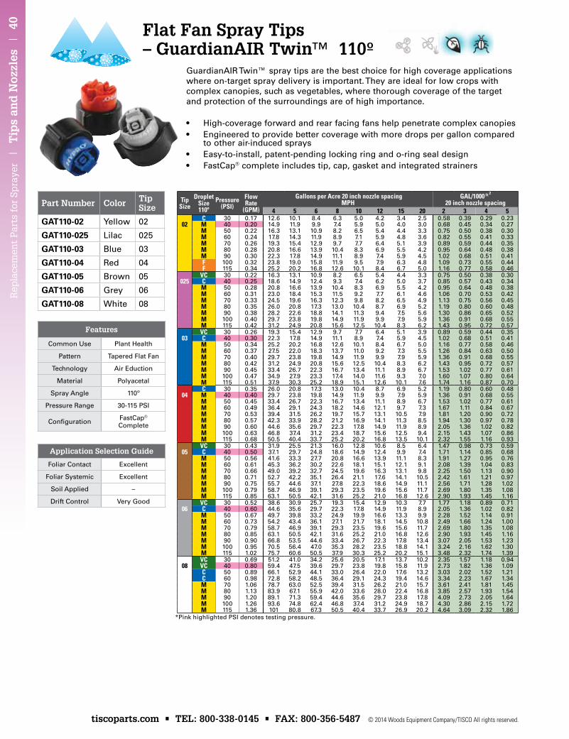
Rep
lace
men
t P
arts
for
Sp
raye
r |
Tip
s an
d N
ozzl
es |
40
tiscoparts.com • TEL: 800-338-0145 • FAX: 800-356-5487 © 2014 Woods Equipment Company/TISCO All rights reserved.
Part Number Color Tip Size
GAT110-02 Yellow 02
GAT110-025 Lilac 025
GAT110-03 Blue 03
GAT110-04 Red 04
GAT110-05 Brown 05
GAT110-06 Grey 06
GAT110-08 White 08
Tip Size
DropletSize110º
Pressure(PSI)
Flow Rate
(GPM)
Gallons per Acre 20 inch nozzle spacing MPH
GAL/1000 Ft 2
20 inch nozzle spacing4 5 6 8 10 12 15 20 2 3 4 5
C 30 0.17 12.6 10.1 8.4 6.3 5.0 4.2 3.4 2.5 0.58 0.39 0.29 0.2302 M 40 0.20 14.9 11.9 9.9 7.4 5.9 5.0 4.0 3.0 0.68 0.45 0.34 0.27
M 50 0.22 16.3 13.1 10.9 8.2 6.5 5.4 4.4 3.3 0.75 0.50 0.38 0.30M 60 0.24 17.8 14.3 11.9 8.9 7.1 5.9 4.8 3.6 0.82 0.55 0.41 0.33M 70 0.26 19.3 15.4 12.9 9.7 7.7 6.4 5.1 3.9 0.89 0.59 0.44 0.35M 80 0.28 20.8 16.6 13.9 10.4 8.3 6.9 5.5 4.2 0.95 0.64 0.48 0.38M 90 0.30 22.3 17.8 14.9 11.1 8.9 7.4 5.9 4.5 1.02 0.68 0.51 0.41F 100 0.32 23.8 19.0 15.8 11.9 9.5 7.9 6.3 4.8 1.09 0.73 0.55 0.44F 115 0.34 25.2 20.2 16.8 12.6 10.1 8.4 6.7 5.0 1.16 0.77 0.58 0.46
VC 30 0.22 16.3 13.1 10.9 8.2 6.5 5.4 4.4 3.3 0.75 0.50 0.38 0.30025 C 40 0.25 18.6 14.9 12.4 9.3 7.4 6.2 5.0 3.7 0.85 0.57 0.43 0.34
M 50 0.28 20.8 16.6 13.9 10.4 8.3 6.9 5.5 4.2 0.95 0.64 0.48 0.38M 60 0.31 23.0 18.4 15.3 11.5 9.2 7.7 6.1 4.6 1.06 0.70 0.53 0.42M 70 0.33 24.5 19.6 16.3 12.3 9.8 8.2 6.5 4.9 1.13 0.75 0.56 0.45M 80 0.35 26.0 20.8 17.3 13.0 10.4 8.7 6.9 5.2 1.19 0.80 0.60 0.48M 90 0.38 28.2 22.6 18.8 14.1 11.3 9.4 7.5 5.6 1.30 0.86 0.65 0.52M 100 0.40 29.7 23.8 19.8 14.9 11.9 9.9 7.9 5.9 1.36 0.91 0.68 0.55M 115 0.42 31.2 24.9 20.8 15.6 12.5 10.4 8.3 6.2 1.43 0.95 0.72 0.57VC 30 0.26 19.3 15.4 12.9 9.7 7.7 6.4 5.1 3.9 0.89 0.59 0.44 0.35
03 C 40 0.30 22.3 17.8 14.9 11.1 8.9 7.4 5.9 4.5 1.02 0.68 0.51 0.41M 50 0.34 25.2 20.2 16.8 12.6 10.1 8.4 6.7 5.0 1.16 0.77 0.58 0.46M 60 0.37 27.5 22.0 18.3 13.7 11.0 9.2 7.3 5.5 1.26 0.84 0.63 0.50M 70 0.40 29.7 23.8 19.8 14.9 11.9 9.9 7.9 5.9 1.36 0.91 0.68 0.55M 80 0.42 31.2 24.9 20.8 15.6 12.5 10.4 8.3 6.2 1.43 0.95 0.72 0.57M 90 0.45 33.4 26.7 22.3 16.7 13.4 11.1 8.9 6.7 1.53 1.02 0.77 0.61M 100 0.47 34.9 27.9 23.3 17.4 14.0 11.6 9.3 7.0 1.60 1.07 0.80 0.64M 115 0.51 37.9 30.3 25.2 18.9 15.1 12.6 10.1 7.6 1.74 1.16 0.87 0.70C 30 0.35 26.0 20.8 17.3 13.0 10.4 8.7 6.9 5.2 1.19 0.80 0.60 0.48
04 M 40 0.40 29.7 23.8 19.8 14.9 11.9 9.9 7.9 5.9 1.36 0.91 0.68 0.55M 50 0.45 33.4 26.7 22.3 16.7 13.4 11.1 8.9 6.7 1.53 1.02 0.77 0.61M 60 0.49 36.4 29.1 24.3 18.2 14.6 12.1 9.7 7.3 1.67 1.11 0.84 0.67M 70 0.53 39.4 31.5 26.2 19.7 15.7 13.1 10.5 7.9 1.81 1.20 0.90 0.72M 80 0.57 42.3 33.9 28.2 21.2 16.9 14.1 11.3 8.5 1.94 1.30 0.97 0.78M 90 0.60 44.6 35.6 29.7 22.3 17.8 14.9 11.9 8.9 2.05 1.36 1.02 0.82M 100 0.63 46.8 37.4 31.2 23.4 18.7 15.6 12.5 9.4 2.15 1.43 1.07 0.86M 115 0.68 50.5 40.4 33.7 25.2 20.2 16.8 13.5 10.1 2.32 1.55 1.16 0.93VC 30 0.43 31.9 25.5 21.3 16.0 12.8 10.6 8.5 6.4 1.47 0.98 0.73 0.59
05 C 40 0.50 37.1 29.7 24.8 18.6 14.9 12.4 9.9 7.4 1.71 1.14 0.85 0.68M 50 0.56 41.6 33.3 27.7 20.8 16.6 13.9 11.1 8.3 1.91 1.27 0.95 0.76M 60 0.61 45.3 36.2 30.2 22.6 18.1 15.1 12.1 9.1 2.08 1.39 1.04 0.83M 70 0.66 49.0 39.2 32.7 24.5 19.6 16.3 13.1 9.8 2.25 1.50 1.13 0.90M 80 0.71 52.7 42.2 35.1 26.4 21.1 17.6 14.1 10.5 2.42 1.61 1.21 0.97M 90 0.75 55.7 44.6 37.1 27.8 22.3 18.6 14.9 11.1 2.56 1.71 1.28 1.02M 100 0.79 58.7 46.9 39.1 29.3 23.5 19.6 15.6 11.7 2.69 1.80 1.35 1.08M 115 0.85 63.1 50.5 42.1 31.6 25.2 21.0 16.8 12.6 2.90 1.93 1.45 1.16VC 30 0.52 38.6 30.9 25.7 19.3 15.4 12.9 10.3 7.7 1.77 1.18 0.89 0.71
06 C 40 0.60 44.6 35.6 29.7 22.3 17.8 14.9 11.9 8.9 2.05 1.36 1.02 0.82M 50 0.67 49.7 39.8 33.2 24.9 19.9 16.6 13.3 9.9 2.28 1.52 1.14 0.91M 60 0.73 54.2 43.4 36.1 27.1 21.7 18.1 14.5 10.8 2.49 1.66 1.24 1.00M 70 0.79 58.7 46.9 39.1 29.3 23.5 19.6 15.6 11.7 2.69 1.80 1.35 1.08M 80 0.85 63.1 50.5 42.1 31.6 25.2 21.0 16.8 12.6 2.90 1.93 1.45 1.16M 90 0.90 66.8 53.5 44.6 33.4 26.7 22.3 17.8 13.4 3.07 2.05 1.53 1.23M 100 0.95 70.5 56.4 47.0 35.3 28.2 23.5 18.8 14.1 3.24 2.16 1.62 1.30M 115 1.02 75.7 60.6 50.5 37.9 30.3 25.2 20.2 15.1 3.48 2.32 1.74 1.39VC 30 0.69 51.2 41.0 34.2 25.6 20.5 17.1 13.7 10.2 2.35 1.57 1.18 0.94
08 VC 40 0.80 59.4 47.5 39.6 29.7 23.8 19.8 15.8 11.9 2.73 1.82 1.36 1.09C 50 0.89 66.1 52.9 44.1 33.0 26.4 22.0 17.6 13.2 3.03 2.02 1.52 1.21C 60 0.98 72.8 58.2 48.5 36.4 29.1 24.3 19.4 14.6 3.34 2.23 1.67 1.34M 70 1.06 78.7 63.0 52.5 39.4 31.5 26.2 21.0 15.7 3.61 2.41 1.81 1.45M 80 1.13 83.9 67.1 55.9 42.0 33.6 28.0 22.4 16.8 3.85 2.57 1.93 1.54M 90 1.20 89.1 71.3 59.4 44.6 35.6 29.7 23.8 17.8 4.09 2.73 2.05 1.64M 100 1.26 93.6 74.8 62.4 46.8 37.4 31.2 24.9 18.7 4.30 2.86 2.15 1.72M 115 1.36 101 80.8 67.3 50.5 40.4 33.7 26.9 20.2 4.64 3.09 2.32 1.86
*Pink highlighted PSI denotes testing pressure.
• High-coverage forward and rear facing fans help penetrate complex canopies• Engineered to provide better coverage with more drops per gallon compared
to other air-induced sprays• Easy-to-install, patent-pending locking ring and o-ring seal design• FastCap® complete includes tip, cap, gasket and integrated strainers
GuardianAIR Twin™ spray tips are the best choice for high coverage applications where on-target spray delivery is important. They are ideal for low crops with complex canopies, such as vegetables, where thorough coverage of the target and protection of the surroundings are of high importance.
Application Selection Guide
Foliar Contact Excellent
Foliar Systemic Excellent
Soil Applied –
Drift Control Very Good
Features
Common Use Plant Health
Pattern Tapered Flat Fan
Technology Air Eduction
Material Polyacetal
Spray Angle 110º
Pressure Range 30-115 PSI
Configuration FastCap® Complete
Flat Fan Spray Tips – GuardianAIR Twin™ 110º
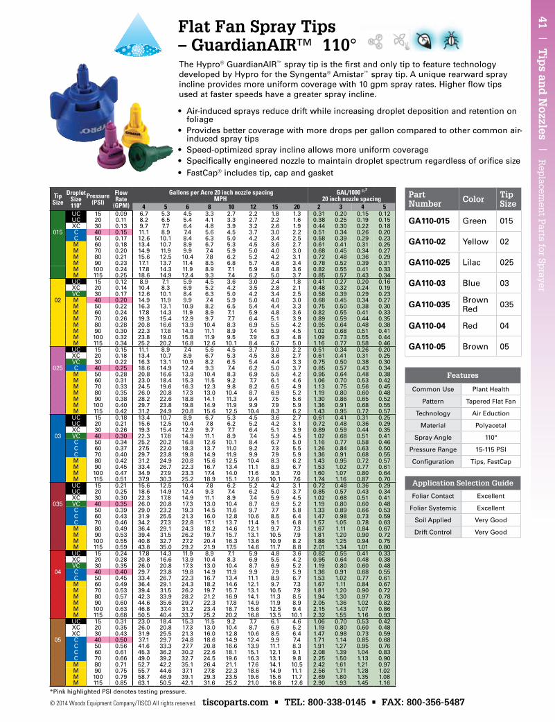
41 | T
ips an
d N
ozzles | R
eplacem
ent P
arts for Sprayer
© 2014 Woods Equipment Company/TISCO All rights reserved. tiscoparts.com • TEL: 800-338-0145 • FAX: 800-356-5487
Part Number Color Tip
Size
GA110-015 Green 015
GA110-02 Yellow 02
GA110-025 Lilac 025
GA110-03 Blue 03
GA110-035 Brown Red 035
GA110-04 Red 04
GA110-05 Brown 05
TipSize
DropletSize110º
Pressure(PSI)
Flow Rate
(GPM)
Gallons per Acre 20 inch nozzle spacing MPH
GAL/1000 Ft 2 20 inch nozzle spacing
4 5 6 8 10 12 15 20 2 3 4 5UC 15 0.09 6.7 5.3 4.5 3.3 2.7 2.2 1.8 1.3 0.31 0.20 0.15 0.12UC 20 0.11 8.2 6.5 5.4 4.1 3.3 2.7 2.2 1.6 0.38 0.25 0.19 0.15XC 30 0.13 9.7 7.7 6.4 4.8 3.9 3.2 2.6 1.9 0.44 0.30 0.22 0.18
015 C 40 0.15 11.1 8.9 7.4 5.6 4.5 3.7 3.0 2.2 0.51 0.34 0.26 0.20C 50 0.17 12.6 10.1 8.4 6.3 5.0 4.2 3.4 2.5 0.58 0.39 0.29 0.23M 60 0.18 13.4 10.7 8.9 6.7 5.3 4.5 3.6 2.7 0.61 0.41 0.31 0.25M 70 0.20 14.9 11.9 9.9 7.4 5.9 5.0 4.0 3.0 0.68 0.45 0.34 0.27M 80 0.21 15.6 12.5 10.4 7.8 6.2 5.2 4.2 3.1 0.72 0.48 0.36 0.29M 90 0.23 17.1 13.7 11.4 8.5 6.8 5.7 4.6 3.4 0.78 0.52 0.39 0.31M 100 0.24 17.8 14.3 11.9 8.9 7.1 5.9 4.8 3.6 0.82 0.55 0.41 0.33M 115 0.25 18.6 14.9 12.4 9.3 7.4 6.2 5.0 3.7 0.85 0.57 0.43 0.34UC 15 0.12 8.9 7.1 5.9 4.5 3.6 3.0 2.4 1.8 0.41 0.27 0.20 0.16XC 20 0.14 10.4 8.3 6.9 5.2 4.2 3.5 2.8 2.1 0.48 0.32 0.24 0.19VC 30 0.17 12.6 10.1 8.4 6.3 5.0 4.2 3.4 2.5 0.58 0.39 0.29 0.23
02 M 40 0.20 14.9 11.9 9.9 7.4 5.9 5.0 4.0 3.0 0.68 0.45 0.34 0.27M 50 0.22 16.3 13.1 10.9 8.2 6.5 5.4 4.4 3.3 0.75 0.50 0.38 0.30M 60 0.24 17.8 14.3 11.9 8.9 7.1 5.9 4.8 3.6 0.82 0.55 0.41 0.33M 70 0.26 19.3 15.4 12.9 9.7 7.7 6.4 5.1 3.9 0.89 0.59 0.44 0.35M 80 0.28 20.8 16.6 13.9 10.4 8.3 6.9 5.5 4.2 0.95 0.64 0.48 0.38M 90 0.30 22.3 17.8 14.9 11.1 8.9 7.4 5.9 4.5 1.02 0.68 0.51 0.41M 100 0.32 23.8 19.0 15.8 11.9 9.5 7.9 6.3 4.8 1.09 0.73 0.55 0.44M 115 0.34 25.2 20.2 16.8 12.6 10.1 8.4 6.7 5.0 1.16 0.77 0.58 0.46UC 15 0.15 11.1 8.9 7.4 5.6 4.5 3.7 3.0 2.2 0.51 0.34 0.26 0.20XC 20 0.18 13.4 10.7 8.9 6.7 5.3 4.5 3.6 2.7 0.61 0.41 0.31 0.25VC 30 0.22 16.3 13.1 10.9 8.2 6.5 5.4 4.4 3.3 0.75 0.50 0.38 0.30
025 C 40 0.25 18.6 14.9 12.4 9.3 7.4 6.2 5.0 3.7 0.85 0.57 0.43 0.34M 50 0.28 20.8 16.6 13.9 10.4 8.3 6.9 5.5 4.2 0.95 0.64 0.48 0.38M 60 0.31 23.0 18.4 15.3 11.5 9.2 7.7 6.1 4.6 1.06 0.70 0.53 0.42M 70 0.33 24.5 19.6 16.3 12.3 9.8 8.2 6.5 4.9 1.13 0.75 0.56 0.45M 80 0.35 26.0 20.8 17.3 13.0 10.4 8.7 6.9 5.2 1.19 0.80 0.60 0.48M 90 0.38 28.2 22.6 18.8 14.1 11.3 9.4 7.5 5.6 1.30 0.86 0.65 0.52M 100 0.40 29.7 23.8 19.8 14.9 11.9 9.9 7.9 5.9 1.36 0.91 0.68 0.55M 115 0.42 31.2 24.9 20.8 15.6 12.5 10.4 8.3 6.2 1.43 0.95 0.72 0.57UC 15 0.18 13.4 10.7 8.9 6.7 5.3 4.5 3.6 2.7 0.61 0.41 0.31 0.25UC 20 0.21 15.6 12.5 10.4 7.8 6.2 5.2 4.2 3.1 0.72 0.48 0.36 0.29XC 30 0.26 19.3 15.4 12.9 9.7 7.7 6.4 5.1 3.9 0.89 0.59 0.44 0.35
03 VC 40 0.30 22.3 17.8 14.9 11.1 8.9 7.4 5.9 4.5 1.02 0.68 0.51 0.41C 50 0.34 25.2 20.2 16.8 12.6 10.1 8.4 6.7 5.0 1.16 0.77 0.58 0.46C 60 0.37 27.5 22.0 18.3 13.7 11.0 9.2 7.3 5.5 1.26 0.84 0.63 0.50C 70 0.40 29.7 23.8 19.8 14.9 11.9 9.9 7.9 5.9 1.36 0.91 0.68 0.55M 80 0.42 31.2 24.9 20.8 15.6 12.5 10.4 8.3 6.2 1.43 0.95 0.72 0.57M 90 0.45 33.4 26.7 22.3 16.7 13.4 11.1 8.9 6.7 1.53 1.02 0.77 0.61M 100 0.47 34.9 27.9 23.3 17.4 14.0 11.6 9.3 7.0 1.60 1.07 0.80 0.64M 115 0.51 37.9 30.3 25.2 18.9 15.1 12.6 10.1 7.6 1.74 1.16 0.87 0.70UC 15 0.21 15.6 12.5 10.4 7.8 6.2 5.2 4.2 3.1 0.72 0.48 0.36 0.29UC 20 0.25 18.6 14.9 12.4 9.3 7.4 6.2 5.0 3.7 0.85 0.57 0.43 0.34XC 30 0.30 22.3 17.8 14.9 11.1 8.9 7.4 5.9 4.5 1.02 0.68 0.51 0.41
035 VC 40 0.35 26.0 20.8 17.3 13.0 10.4 8.7 6.9 5.2 1.19 0.80 0.60 0.48C 50 0.39 29.0 23.2 19.3 14.5 11.6 9.7 7.7 5.8 1.33 0.89 0.66 0.53C 60 0.43 31.9 25.5 21.3 16.0 12.8 10.6 8.5 6.4 1.47 0.98 0.73 0.59C 70 0.46 34.2 27.3 22.8 17.1 13.7 11.4 9.1 6.8 1.57 1.05 0.78 0.63M 80 0.49 36.4 29.1 24.3 18.2 14.6 12.1 9.7 7.3 1.67 1.11 0.84 0.67M 90 0.53 39.4 31.5 26.2 19.7 15.7 13.1 10.5 7.9 1.81 1.20 0.90 0.72M 100 0.55 40.8 32.7 27.2 20.4 16.3 13.6 10.9 8.2 1.88 1.25 0.94 0.75M 115 0.59 43.8 35.0 29.2 21.9 17.5 14.6 11.7 8.8 2.01 1.34 1.01 0.80UC 15 0.24 17.8 14.3 11.9 8.9 7.1 5.9 4.8 3.6 0.82 0.55 0.41 0.33XC 20 0.28 20.8 16.6 13.9 10.4 8.3 6.9 5.5 4.2 0.95 0.64 0.48 0.38VC 30 0.35 26.0 20.8 17.3 13.0 10.4 8.7 6.9 5.2 1.19 0.80 0.60 0.48
04 C 40 0.40 29.7 23.8 19.8 14.9 11.9 9.9 7.9 5.9 1.36 0.91 0.68 0.55C 50 0.45 33.4 26.7 22.3 16.7 13.4 11.1 8.9 6.7 1.53 1.02 0.77 0.61M 60 0.49 36.4 29.1 24.3 18.2 14.6 12.1 9.7 7.3 1.67 1.11 0.84 0.67M 70 0.53 39.4 31.5 26.2 19.7 15.7 13.1 10.5 7.9 1.81 1.20 0.90 0.72M 80 0.57 42.3 33.9 28.2 21.2 16.9 14.1 11.3 8.5 1.94 1.30 0.97 0.78M 90 0.60 44.6 35.6 29.7 22.3 17.8 14.9 11.9 8.9 2.05 1.36 1.02 0.82M 100 0.63 46.8 37.4 31.2 23.4 18.7 15.6 12.5 9.4 2.15 1.43 1.07 0.86M 115 0.68 50.5 40.4 33.7 25.2 20.2 16.8 13.5 10.1 2.32 1.55 1.16 0.93UC 15 0.31 23.0 18.4 15.3 11.5 9.2 7.7 6.1 4.6 1.06 0.70 0.53 0.42XC 20 0.35 26.0 20.8 17.3 13.0 10.4 8.7 6.9 5.2 1.19 0.80 0.60 0.48XC 30 0.43 31.9 25.5 21.3 16.0 12.8 10.6 8.5 6.4 1.47 0.98 0.73 0.59
05 C 40 0.50 37.1 29.7 24.8 18.6 14.9 12.4 9.9 7.4 1.71 1.14 0.85 0.68C 50 0.56 41.6 33.3 27.7 20.8 16.6 13.9 11.1 8.3 1.91 1.27 0.95 0.76C 60 0.61 45.3 36.2 30.2 22.6 18.1 15.1 12.1 9.1 2.08 1.39 1.04 0.83C 70 0.66 49.0 39.2 32.7 24.5 19.6 16.3 13.1 9.8 2.25 1.50 1.13 0.90M 80 0.71 52.7 42.2 35.1 26.4 21.1 17.6 14.1 10.5 2.42 1.61 1.21 0.97M 90 0.75 55.7 44.6 37.1 27.8 22.3 18.6 14.9 11.1 2.56 1.71 1.28 1.02M 100 0.79 58.7 46.9 39.1 29.3 23.5 19.6 15.6 11.7 2.69 1.80 1.35 1.08M 115 0.85 63.1 50.5 42.1 31.6 25.2 21.0 16.8 12.6 2.90 1.93 1.45 1.16
Flat Fan Spray Tips – GuardianAIR™ 110°
• Air-induced sprays reduce drift while increasing droplet deposition and retention on foliage
• Provides better coverage with more drops per gallon compared to other common air-induced spray tips
• Speed-optimized spray incline allows more uniform coverage • Specifically engineered nozzle to maintain droplet spectrum regardless of orifice size• FastCap® includes tip, cap and gasket
The Hypro® GuardianAIR™ spray tip is the first and only tip to feature technology developed by Hypro for the Syngenta® Amistar™ spray tip. A unique rearward spray incline provides more uniform coverage with 10 gpm spray rates. Higher flow tips used at faster speeds have a greater spray incline.
Application Selection Guide
Foliar Contact Excellent
Foliar Systemic Excellent
Soil Applied Very Good
Drift Control Very Good
Features
Common Use Plant Health
Pattern Tapered Flat Fan
Technology Air Eduction
Material Polyacetal
Spray Angle 110º
Pressure Range 15-115 PSI
Configuration Tips, FastCap
*Pink highlighted PSI denotes testing pressure.
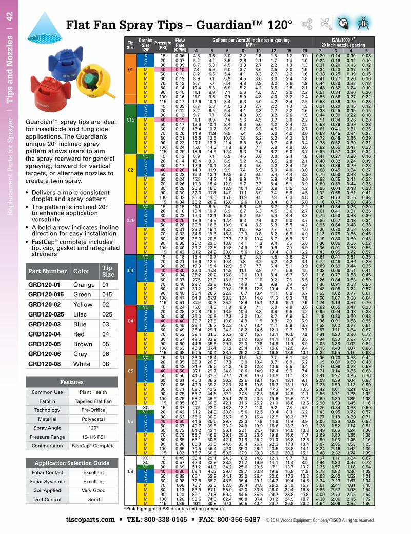
Rep
lace
men
t P
arts
for
Sp
raye
r |
Tip
s an
d N
ozzl
es |
42
tiscoparts.com • TEL: 800-338-0145 • FAX: 800-356-5487 © 2014 Woods Equipment Company/TISCO All rights reserved.
• Delivers a more consistent droplet and spray pattern
• The pattern is inclined 20° to enhance application versatility
• A bold arrow indicates incline direction for easy installation
• FastCap® complete includes tip, cap, gasket and integrated strainers
Guardian™ spray tips are ideal for insecticide and fungicide applications. The Guardian’s unique 20° inclined spray pattern allows users to aim the spray rearward for general spraying, forward for vertical targets, or alternate nozzles to create a twin spray.
TipSize
DropletSize120º
Pressure(PSI)
Flow Rate
(GPM)
Gallons per Acre 20 inch nozzle spacing MPH
GAL/1000 Ft 2
20 inch nozzle spacing4 5 6 8 10 12 15 20 2 3 4 5
C 15 0.06 4.5 3.6 3.0 2.2 1.8 1.5 1.2 0.9 0.20 0.14 0.10 0.08C 20 0.07 5.2 4.2 3.5 2.6 2.1 1.7 1.4 1.0 0.24 0.16 0.12 0.10C 30 0.09 6.7 5.3 4.5 3.3 2.7 2.2 1.8 1.3 0.31 0.20 0.15 0.12
01 M 40 0.10 7.4 5.9 5.0 3.7 3.0 2.5 2.0 1.5 0.34 0.23 0.17 0.14M 50 0.11 8.2 6.5 5.4 4.1 3.3 2.7 2.2 1.6 0.38 0.25 0.19 0.15M 60 0.12 8.9 7.1 5.9 4.5 3.6 3.0 2.4 1.8 0.41 0.27 0.20 0.16M 70 0.13 9.7 7.7 6.4 4.8 3.9 3.2 2.6 1.9 0.44 0.30 0.22 0.18M 80 0.14 10.4 8.3 6.9 5.2 4.2 3.5 2.8 2.1 0.48 0.32 0.24 0.19M 90 0.15 11.1 8.9 7.4 5.6 4.5 3.7 3.0 2.2 0.51 0.34 0.26 0.20M 100 0.16 11.9 9.5 7.9 5.9 4.8 4.0 3.2 2.4 0.55 0.36 0.27 0.22M 115 0.17 12.6 10.1 8.4 6.3 5.0 4.2 3.4 2.5 0.58 0.39 0.29 0.23C 15 0.09 6.7 5.3 4.5 3.3 2.7 2.2 1.8 1.3 0.31 0.20 0.15 0.12C 20 0.11 8.2 6.5 5.4 4.1 3.3 2.7 2.2 1.6 0.38 0.25 0.19 0.15C 30 0.13 9.7 7.7 6.4 4.8 3.9 3.2 2.6 1.9 0.44 0.30 0.22 0.18
015 M 40 0.15 11.1 8.9 7.4 5.6 4.5 3.7 3.0 2.2 0.51 0.34 0.26 0.20M 50 0.17 12.6 10.1 8.4 6.3 5.0 4.2 3.4 2.5 0.58 0.39 0.29 0.23M 60 0.18 13.4 10.7 8.9 6.7 5.3 4.5 3.6 2.7 0.61 0.41 0.31 0.25M 70 0.20 14.9 11.9 9.9 7.4 5.9 5.0 4.0 3.0 0.68 0.45 0.34 0.27M 80 0.21 15.6 12.5 10.4 7.8 6.2 5.2 4.2 3.1 0.72 0.48 0.36 0.29M 90 0.23 17.1 13.7 11.4 8.5 6.8 5.7 4.6 3.4 0.78 0.52 0.39 0.31M 100 0.24 17.8 14.3 11.9 8.9 7.1 5.9 4.8 3.6 0.82 0.55 0.41 0.33M 115 0.25 18.6 14.9 12.4 9.3 7.4 6.2 5.0 3.7 0.85 0.57 0.43 0.34VC 15 0.12 8.9 7.1 5.9 4.5 3.6 3.0 2.4 1.8 0.41 0.27 0.20 0.16C 20 0.14 10.4 8.3 6.9 5.2 4.2 3.5 2.8 2.1 0.48 0.32 0.24 0.19C 30 0.17 12.6 10.1 8.4 6.3 5.0 4.2 3.4 2.5 0.58 0.39 0.29 0.23
02 C 40 0.20 14.9 11.9 9.9 7.4 5.9 5.0 4.0 3.0 0.68 0.45 0.34 0.27C 50 0.22 16.3 13.1 10.9 8.2 6.5 5.4 4.4 3.3 0.75 0.50 0.38 0.30M 60 0.24 17.8 14.3 11.9 8.9 7.1 5.9 4.8 3.6 0.82 0.55 0.41 0.33M 70 0.26 19.3 15.4 12.9 9.7 7.7 6.4 5.1 3.9 0.89 0.59 0.44 0.35M 80 0.28 20.8 16.6 13.9 10.4 8.3 6.9 5.5 4.2 0.95 0.64 0.48 0.38M 90 0.30 22.3 17.8 14.9 11.1 8.9 7.4 5.9 4.5 1.02 0.68 0.51 0.41M 100 0.32 23.8 19.0 15.8 11.9 9.5 7.9 6.3 4.8 1.09 0.73 0.55 0.44M 115 0.34 25.2 20.2 16.8 12.6 10.1 8.4 6.7 5.0 1.16 0.77 0.58 0.46VC 15 0.15 11.1 8.9 7.4 5.6 4.5 3.7 3.0 2.2 0.51 0.34 0.26 0.20C 20 0.18 13.4 10.7 8.9 6.7 5.3 4.5 3.6 2.7 0.61 0.41 0.31 0.25C 30 0.22 16.3 13.1 10.9 8.2 6.5 5.4 4.4 3.3 0.75 0.50 0.38 0.30
025 C 40 0.25 18.6 14.9 12.4 9.3 7.4 6.2 5.0 3.7 0.85 0.57 0.43 0.34C 50 0.28 20.8 16.6 13.9 10.4 8.3 6.9 5.5 4.2 0.95 0.64 0.48 0.38M 60 0.31 23.0 18.4 15.3 11.5 9.2 7.7 6.1 4.6 1.06 0.70 0.53 0.42M 70 0.33 24.5 19.6 16.3 12.3 9.8 8.2 6.5 4.9 1.13 0.75 0.56 0.45M 80 0.35 26.0 20.8 17.3 13.0 10.4 8.7 6.9 5.2 1.19 0.80 0.60 0.48M 90 0.38 28.2 22.6 18.8 14.1 11.3 9.4 7.5 5.6 1.30 0.86 0.65 0.52M 100 0.40 29.7 23.8 19.8 14.9 11.9 9.9 7.9 5.9 1.36 0.91 0.68 0.55M 115 0.42 31.2 24.9 20.8 15.6 12.5 10.4 8.3 6.2 1.43 0.95 0.72 0.57VC 15 0.18 13.4 10.7 8.9 6.7 5.3 4.5 3.6 2.7 0.61 0.41 0.31 0.25C 20 0.21 15.6 12.5 10.4 7.8 6.2 5.2 4.2 3.1 0.72 0.48 0.36 0.29C 30 0.26 19.3 15.4 12.9 9.7 7.7 6.4 5.1 3.9 0.89 0.59 0.44 0.35
03 C 40 0.30 22.3 17.8 14.9 11.1 8.9 7.4 5.9 4.5 1.02 0.68 0.51 0.41C 50 0.34 25.2 20.2 16.8 12.6 10.1 8.4 6.7 5.0 1.16 0.77 0.58 0.46C 60 0.37 27.5 22.0 18.3 13.7 11.0 9.2 7.3 5.5 1.26 0.84 0.63 0.50M 70 0.40 29.7 23.8 19.8 14.9 11.9 9.9 7.9 5.9 1.36 0.91 0.68 0.55M 80 0.42 31.2 24.9 20.8 15.6 12.5 10.4 8.3 6.2 1.43 0.95 0.72 0.57M 90 0.45 33.4 26.7 22.3 16.7 13.4 11.1 8.9 6.7 1.53 1.02 0.77 0.61M 100 0.47 34.9 27.9 23.3 17.4 14.0 11.6 9.3 7.0 1.60 1.07 0.80 0.64M 115 0.51 37.9 30.3 25.2 18.9 15.1 12.6 10.1 7.6 1.74 1.16 0.87 0.70VC 15 0.24 17.8 14.3 11.9 8.9 7.1 5.9 4.8 3.6 0.82 0.55 0.41 0.33C 20 0.28 20.8 16.6 13.9 10.4 8.3 6.9 5.5 4.2 0.95 0.64 0.48 0.38C 30 0.35 26.0 20.8 17.3 13.0 10.4 8.7 6.9 5.2 1.19 0.80 0.60 0.48
04 C 40 0.40 29.7 23.8 19.8 14.9 11.9 9.9 7.9 5.9 1.36 0.91 0.68 0.55C 50 0.45 33.4 26.7 22.3 16.7 13.4 11.1 8.9 6.7 1.53 1.02 0.77 0.61C 60 0.49 36.4 29.1 24.3 18.2 14.6 12.1 9.7 7.3 1.67 1.11 0.84 0.67M 70 0.53 39.4 31.5 26.2 19.7 15.7 13.1 10.5 7.9 1.81 1.20 0.90 0.72M 80 0.57 42.3 33.9 28.2 21.2 16.9 14.1 11.3 8.5 1.94 1.30 0.97 0.78M 90 0.60 44.6 35.6 29.7 22.3 17.8 14.9 11.9 8.9 2.05 1.36 1.02 0.82M 100 0.63 46.8 37.4 31.2 23.4 18.7 15.6 12.5 9.4 2.15 1.43 1.07 0.86M 115 0.68 50.5 40.4 33.7 25.2 20.2 16.8 13.5 10.1 2.32 1.55 1.16 0.93VC 15 0.31 23.0 18.4 15.3 11.5 9.2 7.7 6.1 4.6 1.06 0.70 0.53 0.42C 20 0.35 26.0 20.8 17.3 13.0 10.4 8.7 6.9 5.2 1.19 0.80 0.60 0.48C 30 0.43 31.9 25.5 21.3 16.0 12.8 10.6 8.5 6.4 1.47 0.98 0.73 0.59
05 C 40 0.50 37.1 29.7 24.8 18.6 14.9 12.4 9.9 7.4 1.71 1.14 0.85 0.68C 50 0.56 41.6 33.3 27.7 20.8 16.6 13.9 11.1 8.3 1.91 1.27 0.95 0.76C 60 0.61 45.3 36.2 30.2 22.6 18.1 15.1 12.1 9.1 2.08 1.39 1.04 0.83M 70 0.66 49.0 39.2 32.7 24.5 19.6 16.3 13.1 9.8 2.25 1.50 1.13 0.90M 80 0.71 52.7 42.2 35.1 26.4 21.1 17.6 14.1 10.5 2.42 1.61 1.21 0.97M 90 0.75 55.7 44.6 37.1 27.8 22.3 18.6 14.9 11.1 2.56 1.71 1.28 1.02M 100 0.79 58.7 46.9 39.1 29.3 23.5 19.6 15.6 11.7 2.69 1.80 1.35 1.08M 115 0.85 63.1 50.5 42.1 31.6 25.2 21.0 16.8 12.6 2.90 1.93 1.45 1.16XC 15 0.37 27.5 22.0 18.3 13.7 11.0 9.2 7.3 5.5 1.26 0.84 0.63 0.50VC 20 0.42 31.2 24.9 20.8 15.6 12.5 10.4 8.3 6.2 1.43 0.95 0.72 0.57C 30 0.52 38.6 30.9 25.7 19.3 15.4 12.9 10.3 7.7 1.77 1.18 0.89 0.71
06 C 40 0.60 44.6 35.6 29.7 22.3 17.8 14.9 11.9 8.9 2.05 1.36 1.02 0.82C 50 0.67 49.7 39.8 33.2 24.9 19.9 16.6 13.3 9.9 2.28 1.52 1.14 0.91C 60 0.73 54.2 43.4 36.1 27.1 21.7 18.1 14.5 10.8 2.49 1.66 1.24 1.00M 70 0.79 58.7 46.9 39.1 29.3 23.5 19.6 15.6 11.7 2.69 1.80 1.35 1.08M 80 0.85 63.1 50.5 42.1 31.6 25.2 21.0 16.8 12.6 2.90 1.93 1.45 1.16M 90 0.90 66.8 53.5 44.6 33.4 26.7 22.3 17.8 13.4 3.07 2.05 1.53 1.23M 100 0.95 70.5 56.4 47.0 35.3 28.2 23.5 18.8 14.1 3.24 2.16 1.62 1.30M 115 1.02 75.7 60.6 50.5 37.9 30.3 25.2 20.2 15.1 3.48 2.32 1.74 1.39XC 15 0.49 36.4 29.1 24.3 18.2 14.6 12.1 9.7 7.3 1.67 1.11 0.84 0.67XC 20 0.57 42.3 33.9 28.2 21.2 16.9 14.1 11.3 8.5 1.94 1.30 0.97 0.78VC 30 0.69 51.2 41.0 34.2 25.6 20.5 17.1 13.7 10.2 2.35 1.57 1.18 0.94
08 C 40 0.80 59.4 47.5 39.6 29.7 23.8 19.8 15.8 11.9 2.73 1.82 1.36 1.09C 50 0.89 66.1 52.9 44.1 33.0 26.4 22.0 17.6 13.2 3.03 2.02 1.52 1.21C 60 0.98 72.8 58.2 48.5 36.4 29.1 24.3 19.4 14.6 3.34 2.23 1.67 1.34M 70 1.06 78.7 63.0 52.5 39.4 31.5 26.2 21.0 15.7 3.61 2.41 1.81 1.45M 80 1.13 83.9 67.1 55.9 42.0 33.6 28.0 22.4 16.8 3.85 2.57 1.93 1.54M 90 1.20 89.1 71.3 59.4 44.6 35.6 29.7 23.8 17.8 4.09 2.73 2.05 1.64M 100 1.26 93.6 74.8 62.4 46.8 37.4 31.2 24.9 18.7 4.30 2.86 2.15 1.72M 115 1.36 101 80.8 67.3 50.5 40.4 33.7 26.9 20.2 4.64 3.09 2.32 1.86
Part Number Color Tip Size
GRD120-01 Orange 01
GRD120-015 Green 015
GRD120-02 Yellow 02
GRD120-025 Lilac 025
GRD120-03 Blue 03
GRD120-04 Red 04
GRD120-05 Brown 05
GRD120-06 Gray 06
GRD120-08 White 08
Flat Fan Spray Tips – Guardian™ 120°
Application Selection Guide
Foliar Contact Excellent
Foliar Systemic Excellent
Soil Applied Very Good
Drift Control Good
Features
Common Use Plant Health
Pattern Tapered Flat Fan
Technology Pre-Orifice
Material Polyacetal
Spray Angle 120º
Pressure Range 15-115 PSI
Configuration FastCap® Complete
*Pink highlighted PSI denotes testing pressure.
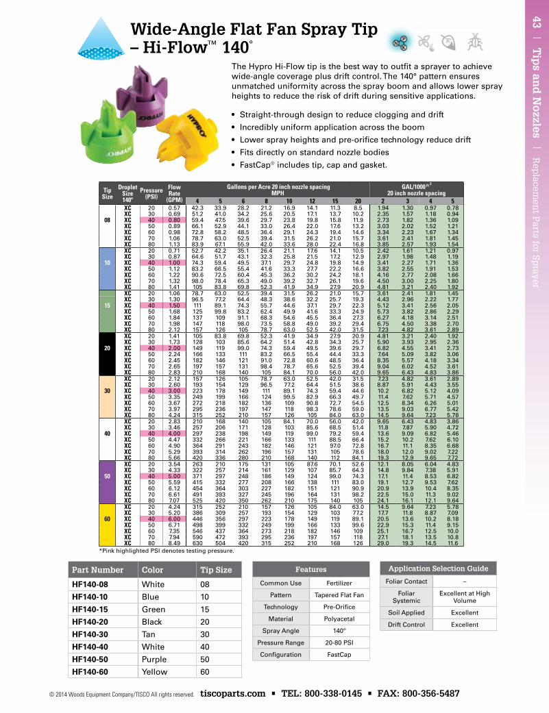
43 | T
ips an
d N
ozzles | R
eplacem
ent P
arts for Sprayer
© 2014 Woods Equipment Company/TISCO All rights reserved. tiscoparts.com • TEL: 800-338-0145 • FAX: 800-356-5487
Part Number Color Tip Size
HF140-08 White 08
HF140-10 Blue 10
HF140-15 Green 15
HF140-20 Black 20
HF140-30 Tan 30
HF140-40 White 40
HF140-50 Purple 50
HF140-60 Yellow 60
TipSize
DropletSize140º
Pressure(PSI)
Flow Rate
(GPM)
Gallons per Acre 20 inch nozzle spacing MPH
GAL/1000 Ft 2 20 inch nozzle spacing
4 5 6 8 10 12 15 20 2 3 4 5XC 20 0.57 42.3 33.9 28.2 21.2 16.9 14.1 11.3 8.5 1.94 1.30 0.97 0.78XC 30 0.69 51.2 41.0 34.2 25.6 20.5 17.1 13.7 10.2 2.35 1.57 1.18 0.94
08 XC 40 0.80 59.4 47.5 39.6 29.7 23.8 19.8 15.8 11.9 2.73 1.82 1.36 1.09XC 50 0.89 66.1 52.9 44.1 33.0 26.4 22.0 17.6 13.2 3.03 2.02 1.52 1.21XC 60 0.98 72.8 58.2 48.5 36.4 29.1 24.3 19.4 14.6 3.34 2.23 1.67 1.34XC 70 1.06 78.7 63.0 52.5 39.4 31.5 26.2 21.0 15.7 3.61 2.41 1.81 1.45XC 80 1.13 83.9 67.1 55.9 42.0 33.6 28.0 22.4 16.8 3.85 2.57 1.93 1.54XC 20 0.71 52.7 42.2 35.1 26.4 21.1 17.6 14.1 10.5 2.42 1.61 1.21 0.97XC 30 0.87 64.6 51.7 43.1 32.3 25.8 21.5 17.2 12.9 2.97 1.98 1.48 1.19
10 XC 40 1.00 74.3 59.4 49.5 37.1 29.7 24.8 19.8 14.9 3.41 2.27 1.71 1.36XC 50 1.12 83.2 66.5 55.4 41.6 33.3 27.7 22.2 16.6 3.82 2.55 1.91 1.53XC 60 1.22 90.6 72.5 60.4 45.3 36.2 30.2 24.2 18.1 4.16 2.77 2.08 1.66XC 70 1.32 98.0 78.4 65.3 49.0 39.2 32.7 26.1 19.6 4.50 3.00 2.25 1.80XC 80 1.41 105 83.8 69.8 52.3 41.9 34.9 27.9 20.9 4.81 3.21 2.40 1.92XC 20 1.06 78.7 63.0 52.5 39.4 31.5 26.2 21.0 15.7 3.61 2.41 1.81 1.45XC 30 1.30 96.5 77.2 64.4 48.3 38.6 32.2 25.7 19.3 4.43 2.96 2.22 1.77
15 XC 40 1.50 111 89.1 74.3 55.7 44.6 37.1 29.7 22.3 5.12 3.41 2.56 2.05XC 50 1.68 125 99.8 83.2 62.4 49.9 41.6 33.3 24.9 5.73 3.82 2.86 2.29XC 60 1.84 137 109 91.1 68.3 54.6 45.5 36.4 27.3 6.27 4.18 3.14 2.51XC 70 1.98 147 118 98.0 73.5 58.8 49.0 39.2 29.4 6.75 4.50 3.38 2.70XC 80 2.12 157 126 105 78.7 63.0 52.5 42.0 31.5 7.23 4.82 3.61 2.89XC 20 1.41 105 83.8 69.8 52.3 41.9 34.9 27.9 20.9 4.81 3.21 2.40 1.92XC 30 1.73 128 103 85.6 64.2 51.4 42.8 34.3 25.7 5.90 3.93 2.95 2.36
20 XC 40 2.00 149 119 99.0 74.3 59.4 49.5 39.6 29.7 6.82 4.55 3.41 2.73XC 50 2.24 166 133 111 83.2 66.5 55.4 44.4 33.3 7.64 5.09 3.82 3.06XC 60 2.45 182 146 121 91.0 72.8 60.6 48.5 36.4 8.35 5.57 4.18 3.34XC 70 2.65 197 157 131 98.4 78.7 65.6 52.5 39.4 9.04 6.02 4.52 3.61XC 80 2.83 210 168 140 105 84.1 70.0 56.0 42.0 9.65 6.43 4.83 3.86XC 20 2.12 157 126 105 78.7 63.0 52.5 42.0 31.5 7.23 4.82 3.61 2.89XC 30 2.60 193 154 129 96.5 77.2 64.4 51.5 38.6 8.87 5.91 4.43 3.55
30 XC 40 3.00 223 178 149 111 89.1 74.3 59.4 44.6 10.2 6.82 5.12 4.09XC 50 3.35 249 199 166 124 99.5 82.9 66.3 49.7 11.4 7.62 5.71 4.57XC 60 3.67 272 218 182 136 109 90.8 72.7 54.5 12.5 8.34 6.26 5.01XC 70 3.97 295 236 197 147 118 98.3 78.6 59.0 13.5 9.03 6.77 5.42XC 80 4.24 315 252 210 157 126 105 84.0 63.0 14.5 9.64 7.23 5.78XC 20 2.83 210 168 140 105 84.1 70.0 56.0 42.0 9.65 6.43 4.83 3.86XC 30 3.46 257 206 171 128 103 85.6 68.5 51.4 11.8 7.87 5.90 4.72
40 XC 40 4.00 297 238 198 149 119 99.0 79.2 59.4 13.6 9.09 6.82 5.46XC 50 4.47 332 266 221 166 133 111 88.5 66.4 15.2 10.2 7.62 6.10XC 60 4.90 364 291 243 182 146 121 97.0 72.8 16.7 11.1 8.35 6.68XC 70 5.29 393 314 262 196 157 131 105 78.6 18.0 12.0 9.02 7.22XC 80 5.66 420 336 280 210 168 140 112 84.1 19.3 12.9 9.65 7.72XC 20 3.54 263 210 175 131 105 87.6 70.1 52.6 12.1 8.05 6.04 4.83XC 30 4.33 322 257 214 161 129 107 85.7 64.3 14.8 9.84 7.38 5.91
50 XC 40 5.00 371 297 248 186 149 124 99.0 74.3 17.1 11.4 8.53 6.82XC 50 5.59 415 332 277 208 166 138 111 83.0 19.1 12.7 9.53 7.62XC 60 6.12 454 364 303 227 182 151 121 90.9 20.9 13.9 10.4 8.35XC 70 6.61 491 393 327 245 196 164 131 98.2 22.5 15.0 11.3 9.02XC 80 7.07 525 420 350 262 210 175 140 105 24.1 16.1 12.1 9.64XC 20 4.24 315 252 210 157 126 105 84.0 63.0 14.5 9.64 7.23 5.78XC 30 5.20 386 309 257 193 154 129 103 77.2 17.7 11.8 8.87 7.09
60 XC 40 6.00 446 356 297 223 178 149 119 89.1 20.5 13.6 10.2 8.18XC 50 6.71 498 399 332 249 199 166 133 99.6 22.9 15.3 11.4 9.15XC 60 7.35 546 437 364 273 218 182 146 109 25.1 16.7 12.5 10.0XC 70 7.94 590 472 393 295 236 197 157 118 27.1 18.1 13.5 10.8XC 80 8.49 630 504 420 315 252 210 168 126 29.0 19.3 14.5 11.6
Wide-Angle Flat Fan Spray Tip – Hi-Flow™ 140°
• Straight-through design to reduce clogging and drift
• Incredibly uniform application across the boom
• Lower spray heights and pre-orifice technology reduce drift
• Fits directly on standard nozzle bodies
• FastCap® includes tip, cap and gasket.
The Hypro Hi-Flow tip is the best way to outfit a sprayer to achieve wide-angle coverage plus drift control. The 140° pattern ensures unmatched uniformity across the spray boom and allows lower spray heights to reduce the risk of drift during sensitive applications.
Application Selection Guide
Foliar Contact –
Foliar Systemic
Excellent at High Volume
Soil Applied Excellent
Drift Control Excellent
Features
Common Use Fertilizer
Pattern Tapered Flat Fan
Technology Pre-Orifice
Material Polyacetal
Spray Angle 140º
Pressure Range 20-80 PSI
Configuration FastCap
*Pink highlighted PSI denotes testing pressure.
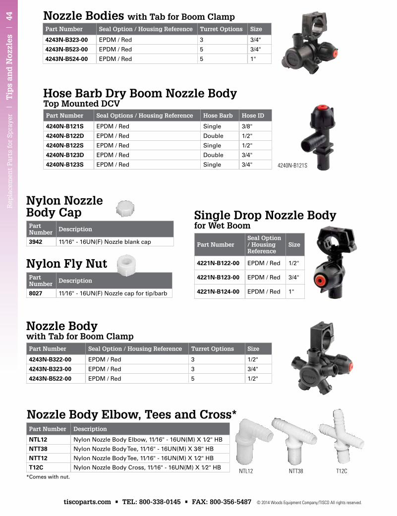
Rep
lace
men
t P
arts
for
Sp
raye
r |
Tip
s an
d N
ozzl
es |
44
tiscoparts.com • TEL: 800-338-0145 • FAX: 800-356-5487 © 2014 Woods Equipment Company/TISCO All rights reserved.
Part Number Seal Option / Housing Reference Turret Options Size
4243N-B323-00 EPDM / Red 3 3/4"
4243N-B523-00 EPDM / Red 5 3/4"
4243N-B524-00 EPDM / Red 5 1"
Part Number Seal Options / Housing Reference Hose Barb Hose ID
4240N-B121S EPDM / Red Single 3/8"
4240N-B122D EPDM / Red Double 1/2"
4240N-B122S EPDM / Red Single 1/2"
4240N-B123D EPDM / Red Double 3/4"
4240N-B123S EPDM / Red Single 3/4"
Part Number Description
3942 11⁄16" - 16UN(F) Nozzle blank cap
Part Number Description
8027 11⁄16" - 16UN(F) Nozzle cap for tip/barb
Part Number Description
NTL12 Nylon Nozzle Body Elbow, 11⁄16" - 16UN(M) X 1⁄2" HB
NTT38 Nylon Nozzle Body Tee, 11⁄16" - 16UN(M) X 3⁄8" HB
NTT12 Nylon Nozzle Body Tee, 11⁄16" - 16UN(M) X 1⁄2" HB
T12C Nylon Nozzle Body Cross, 11⁄16" - 16UN(M) X 1⁄2" HB
Part NumberSeal Option / Housing Reference
Size
4221N-B122-00 EPDM / Red 1/2"
4221N-B123-00 EPDM / Red 3/4"
4221N-B124-00 EPDM / Red 1"
Part Number Seal Option / Housing Reference Turret Options Size
4243N-B322-00 EPDM / Red 3 1/2"
4243N-B323-00 EPDM / Red 3 3/4"
4243N-B522-00 EPDM / Red 5 1/2"
Nozzle Bodies with Tab for Boom Clamp
Hose Barb Dry Boom Nozzle Body Top Mounted DCV
Nylon Nozzle Body Cap
Nylon Fly Nut
Single Drop Nozzle Body for Wet Boom
Nozzle Bodywith Tab for Boom Clamp
Nozzle Body Elbow, Tees and Cross*
NTL12 NTT38 T12C
4240N-B121S
*Comes with nut.
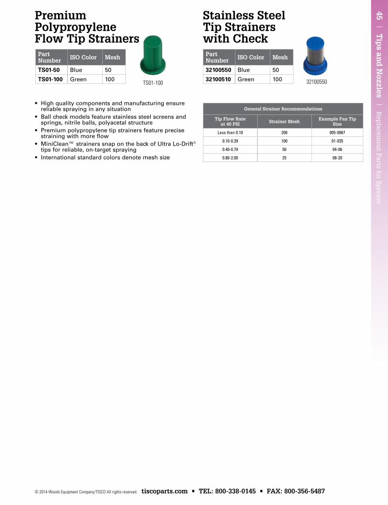
45 | T
ips an
d N
ozzles | R
eplacem
ent P
arts for Sprayer
© 2014 Woods Equipment Company/TISCO All rights reserved. tiscoparts.com • TEL: 800-338-0145 • FAX: 800-356-5487
Part Number ISO Color Mesh
TS01-50 Blue 50
TS01-100 Green 100
Part Number ISO Color Mesh
32100550 Blue 50
32100510 Green 100
Premium Polypropylene Flow Tip Strainers
Stainless Steel Tip Strainers with Check
TS01-100 32100550
• High quality components and manufacturing ensure reliable spraying in any situation
• Ball check models feature stainless steel screens and springs, nitrile balls, polyacetal structure
• Premium polypropylene tip strainers feature precise straining with more flow
• MiniClean™ strainers snap on the back of Ultra Lo-Drift® tips for reliable, on-target spraying
• International standard colors denote mesh size
General Strainer Recommendations
Tip Flow Rate at 40 PSI Strainer Mesh Example Fan Tip
Size
Less than 0.10 200 005-0067
0.10-0.39 100 01-035
0.40-0.79 50 04-06
0.80-2.00 25 08-20
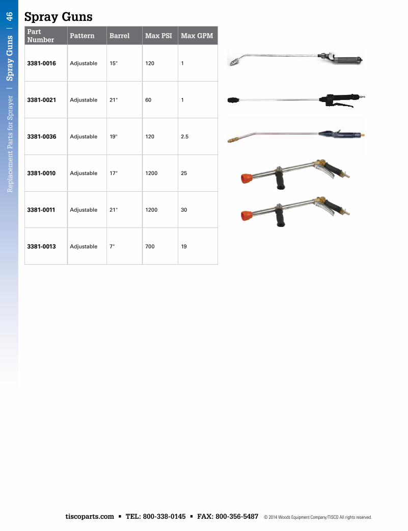
Rep
lace
men
t P
arts
for
Sp
raye
r |
Sp
ray
Gu
ns
| 4
6
tiscoparts.com • TEL: 800-338-0145 • FAX: 800-356-5487 © 2014 Woods Equipment Company/TISCO All rights reserved.
Spray GunsPart Number
Pattern Barrel Max PSI Max GPM
3381-0016 Adjustable 15" 120 1
3381-0021 Adjustable 21" 60 1
3381-0036 Adjustable 19" 120 2.5
3381-0010 Adjustable 17" 1200 25
3381-0011 Adjustable 21" 1200 30
3381-0013 Adjustable 7" 700 19
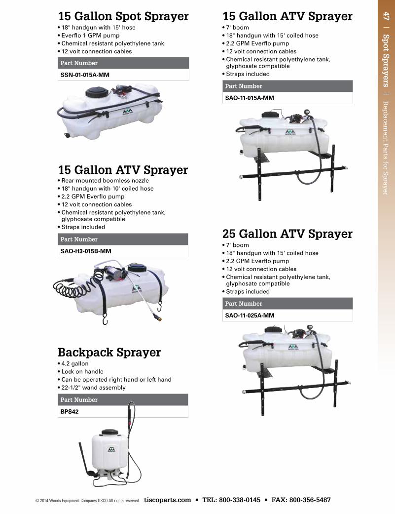
47 | Sp
ot Sprayers |
Rep
lacemen
t Parts for Sp
rayer
© 2014 Woods Equipment Company/TISCO All rights reserved. tiscoparts.com • TEL: 800-338-0145 • FAX: 800-356-5487
15 Gallon Spot Sprayer•18"handgunwith15'hose•Everflo1GPMpump•Chemicalresistantpolyethylenetank•12voltconnectioncables
15 Gallon ATV Sprayer•7'boom•18"handgunwith15'coiledhose•2.2GPMEverflopump•12voltconnectioncables•Chemicalresistantpolyethylenetank,
glyphosate compatible•Strapsincluded
25 Gallon ATV Sprayer•7' boom•18"handgunwith15'coiledhose•2.2GPMEverflopump•12voltconnectioncables•Chemicalresistantpolyethylenetank,
glyphosate compatible•Strapsincluded
Backpack Sprayer•4.2gallon•Lockonhandle•Canbeoperatedrighthandorlefthand•22-1/2"wandassembly
• Rear mounted boomless nozzle•18"handgunwith10'coiledhose•2.2GPMEverflopump•12voltconnectioncables•Chemicalresistantpolyethylenetank,
glyphosate compatible•Strapsincluded
15 Gallon ATV Sprayer
Part Number
SSN-01-015A-MM
Part Number
SAo-H3-015b-MM
Part Number
bPS42
Part Number
SAo-11-015A-MM
Part Number
SAo-11-025A-MM
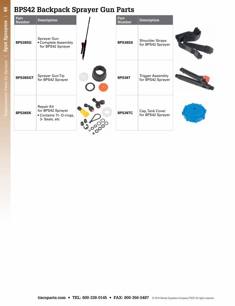
Rep
lace
men
t P
arts
for
Sp
raye
r |
Sp
ot S
pra
yers
| 4
8
tiscoparts.com • TEL: 800-338-0145 • FAX: 800-356-5487 © 2014 Woods Equipment Company/TISCO All rights reserved.
Part Number Description
bPS38SGSprayer Gun •CompleteAssembly
for BPS42 Sprayer
bPS38SGT Sprayer Gun Tip for BPS42 Sprayer
bPS38SK
Repair Kit for BPS42 Sprayer•Contains11-O-rings,
3- Seals, etc
Part Number Description
bPS38SS Shoulder Straps for BPS42 Sprayer
bPS38T Trigger Assembly for BPS42 Sprayer
bPS38TC Cap, Tank Cover for BPS42 Sprayer
BPS42 Backpack Sprayer Gun Parts