rental services temporary cooling - flexible water … personal safety and the proper operation of...
TRANSCRIPT
Engineering Bulletin
Rental Services Temporary Cooling - Flexible Water Hose
September 2006 CHS-PRB007-EN
Engineering Bulletin
Warnings and Cautions
© 2006 American Standard All rights reserved Rental Services Temporary Cooling - Flexible Water Hose • CHS-PRB007-EN
Warnings and Cautions. Notice that warnings and cautions appear at appropriate intervals throughout this manual. Warnings are provided to alert installing parties of potential hazards that could result in personal injury or death, while cautions are designed to alert personnel to conditions that could result in equipment damage.
Your personal safety and the proper operation of the Trane Rental Services temporary chilled water system depend upon the strict observance of these precautions.
NOTICE: Warnings and Cautions appear at appropriate sections throughout this literature. Read these carefully.
� WARNING: Indicates a potentially hazardous situation which, if not avoided, could result in death or serious injury.
� CAUTION: Indicates a potentially hazardous situation which, if not avoided, may result in minor or moderate injury. It may also be used to alert against unsafe practices.
CAUTION: Indicates a situation that may result in equipment or property-damage only accidents.
CHS-PRB007-EN • Rental Services Temporary Cooling - Flexible Water Hose 3
Warnings and Cautions . . . . . . . . . . . . . . . . . . . . . . . . . . . . . . . . . . . . . . . . . . . . . . . . 2
Introduction . . . . . . . . . . . . . . . . . . . . . . . . . . . . . . . . . . . . . . . . . . . . . . . . . . . . . . . 4
Units Affected . . . . . . . . . . . . . . . . . . . . . . . . . . . . . . . . . . . . . . . . . . . . . . . . . . . . . 5Chillers . . . . . . . . . . . . . . . . . . . . . . . . . . . . . . . . . . . . . . . . . . . . . . . . . . . . . . . . . . 5Hose Boxes . . . . . . . . . . . . . . . . . . . . . . . . . . . . . . . . . . . . . . . . . . . . . . . . . . . . . . 5
General Information . . . . . . . . . . . . . . . . . . . . . . . . . . . . . . . . . . . . . . . . . . . . . . . . 6Weights and Dimensions . . . . . . . . . . . . . . . . . . . . . . . . . . . . . . . . . . . . . . . . . . . 6Contents of Hose Box . . . . . . . . . . . . . . . . . . . . . . . . . . . . . . . . . . . . . . . . . . . . . . 7
Component Specification . . . . . . . . . . . . . . . . . . . . . . . . . . . . . . . . . . . . . . . . . . . 8All Hose Sizes . . . . . . . . . . . . . . . . . . . . . . . . . . . . . . . . . . . . . . . . . . . . . . . . . . . . 8For 2.5-in and 4-in Hose Boxes Only . . . . . . . . . . . . . . . . . . . . . . . . . . . . . . . . . . 9Pressure Loss of Flex Hose . . . . . . . . . . . . . . . . . . . . . . . . . . . . . . . . . . . . . . . . . 9
Installation Instructions. . . . . . . . . . . . . . . . . . . . . . . . . . . . . . . . . . . . . . . . . . . . .10Dixon Coupling . . . . . . . . . . . . . . . . . . . . . . . . . . . . . . . . . . . . . . . . . . . . . . . . . . 11Proper Hose Installation Guidelines . . . . . . . . . . . . . . . . . . . . . . . . . . . . . . . . . 11Horizontal Hose Installation . . . . . . . . . . . . . . . . . . . . . . . . . . . . . . . . . . . . . . . . 11
Figure 1. Correct Horizontal Hose Installation . . . . . . . . . . . . . . . . . . . . . . . . . . . 11Figure 2. Incorrect Horizontal Hose Installation . . . . . . . . . . . . . . . . . . . . . . . . . 12
Vertical Hose Installation . . . . . . . . . . . . . . . . . . . . . . . . . . . . . . . . . . . . . . . . . . 12Figure 3. Correct Vertical Hose Installation . . . . . . . . . . . . . . . . . . . . . . . . . . . . . 12Figure 4. Incorrect Vertical Hose Installation. . . . . . . . . . . . . . . . . . . . . . . . . . . . 13
Horizontal to Vertical Hose Installation . . . . . . . . . . . . . . . . . . . . . . . . . . . . . . . 13Figure 5. Correct Horizontal/Vertical Installation. . . . . . . . . . . . . . . . . . . . . . . . . 14Figure 6. Incorrect Horizontal/Vertical Installation . . . . . . . . . . . . . . . . . . . . . . . 14Figure 7. Correct Unsupported Horizontal Installation . . . . . . . . . . . . . . . . . . . . 15
Material Disposition . . . . . . . . . . . . . . . . . . . . . . . . . . . . . . . . . . . . . . . . . . . . . . 15Exceptions . . . . . . . . . . . . . . . . . . . . . . . . . . . . . . . . . . . . . . . . . . . . . . . . . . . . . . 15Hard Pipe Installation . . . . . . . . . . . . . . . . . . . . . . . . . . . . . . . . . . . . . . . . . . . . . 15
Contents
4 Rental Services Temporary Cooling - Flexible Water Hose • CHS-PRB007-EN
This bulletin covers the flexible water hose available to rent for temporary cooling solutions. This includes box contents, technical information on each component, and proper flexible water hose installation.
Trane Rental Services offers several sizes of flexible water hose to rent for customers with temporary cooling needs. The hose is proof tested to 150 psig. Trane provides a system of Victaulic® couplings, fittings, and various lengths of hose to provide consistent, rapid deployment of water chillers for temporary applications. The flexible water hose is intended for outdoor, horizontal runs connecting the inlet and outlet of the chiller and pump(s) to the building’s existing chilled water system. Call Trane Rental Services 24 x 7 at (800) 755-5115 for specific questions.
Introduction
CHS-PRB007-EN • Rental Services Temporary Cooling - Flexible Water Hose 5
Chillers
CSCA0010 – CSCA0060 (CGAC/D/E/F)
CSCA0080 – CSCA0400 (RTAA)
CSCA0155 – CSCA0500 (RTAC)
CSCW0300 – CSCW1250 (CVHE/F)
Hose Boxes
CSCH002xx – 2.5 in nominal hose size
CSCH004xx – 4.0 in nominal hose size
CSCH006xx – 6.0 in nominal hose size
CSCH008xx – 8.0 in nominal hose size
CSCH010xx – 10.0 in nominal hose size
Note: Where xx represents the unique inventory number of the hose box.
Units Affected
6 Rental Services Temporary Cooling - Flexible Water Hose • CHS-PRB007-EN
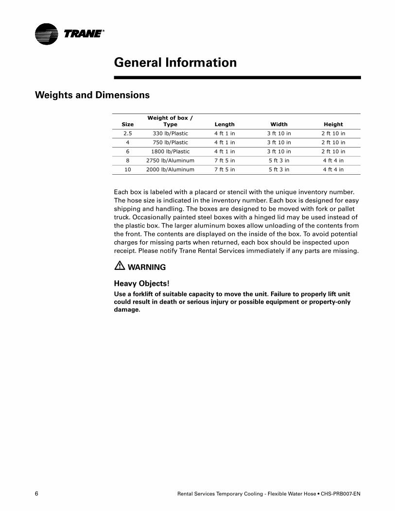
Weights and Dimensions
Each box is labeled with a placard or stencil with the unique inventory number. The hose size is indicated in the inventory number. Each box is designed for easy shipping and handling. The boxes are designed to be moved with fork or pallet truck. Occasionally painted steel boxes with a hinged lid may be used instead of the plastic box. The larger aluminum boxes allow unloading of the contents from the front. The contents are displayed on the inside of the box. To avoid potential charges for missing parts when returned, each box should be inspected upon receipt. Please notify Trane Rental Services immediately if any parts are missing.
� WARNING
Heavy Objects!
Use a forklift of suitable capacity to move the unit. Failure to properly lift unit
could result in death or serious injury or possible equipment or property-only
damage.
General Information
SizeWeight of box /
Type Length Width Height
2.5 330 lb/Plastic 4 ft 1 in 3 ft 10 in 2 ft 10 in
4 750 lb/Plastic 4 ft 1 in 3 ft 10 in 2 ft 10 in
6 1800 lb/Plastic 4 ft 1 in 3 ft 10 in 2 ft 10 in
8 2750 lb/Aluminum 7 ft 5 in 5 ft 3 in 4 ft 4 in
10 2000 lb/Aluminum 7 ft 5 in 5 ft 3 in 4 ft 4 in
CHS-PRB007-EN • Rental Services Temporary Cooling - Flexible Water Hose 7
General Information
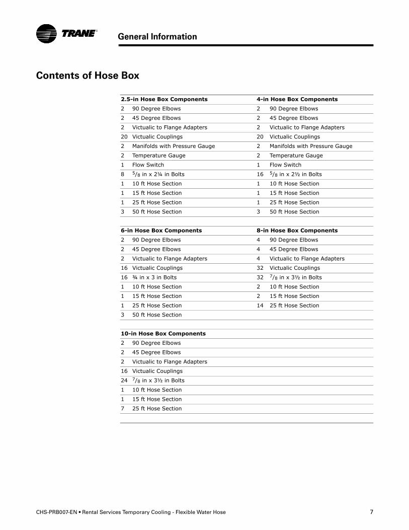
Contents of Hose Box
2.5-in Hose Box Components 4-in Hose Box Components
2 90 Degree Elbows 2 90 Degree Elbows
2 45 Degree Elbows 2 45 Degree Elbows
2 Victualic to Flange Adapters 2 Victualic to Flange Adapters
20 Victualic Couplings 20 Victualic Couplings
2 Manifolds with Pressure Gauge 2 Manifolds with Pressure Gauge
2 Temperature Gauge 2 Temperature Gauge
1 Flow Switch 1 Flow Switch
8 5/8 in x 2¼ in Bolts 16 5/8 in x 2½ in Bolts
1 10 ft Hose Section 1 10 ft Hose Section
1 15 ft Hose Section 1 15 ft Hose Section
1 25 ft Hose Section 1 25 ft Hose Section
3 50 ft Hose Section 3 50 ft Hose Section
6-in Hose Box Components 8-in Hose Box Components
2 90 Degree Elbows 4 90 Degree Elbows
2 45 Degree Elbows 4 45 Degree Elbows
2 Victualic to Flange Adapters 4 Victualic to Flange Adapters
16 Victualic Couplings 32 Victualic Couplings
16 ¾ in x 3 in Bolts 32 7/8 in x 3½ in Bolts
1 10 ft Hose Section 2 10 ft Hose Section
1 15 ft Hose Section 2 15 ft Hose Section
1 25 ft Hose Section 14 25 ft Hose Section
3 50 ft Hose Section
10-in Hose Box Components
2 90 Degree Elbows
2 45 Degree Elbows
2 Victualic to Flange Adapters
16 Victualic Couplings
24 7/8 in x 3½ in Bolts
1 10 ft Hose Section
1 15 ft Hose Section
7 25 ft Hose Section
8 Rental Services Temporary Cooling - Flexible Water Hose • CHS-PRB007-EN
All Hose Sizes
• Hose Material: The hose is premium quality, through-the-weave extruded potable water transport hose. Hose is rated NSF61 for transport of potable water. Exterior jacket is polyurethane. Hose is rated for -36°F to 150°F working temperature range. Minimum safe working pressure is 150 psig. Hose is ozone resistant.
• Hose end fittings: Victaulic® type couplings of anodized aluminum.
• Hose to Victaulic grooved end fittings connection: Factory installed band-on type (Band-It™) connections for excellent coupling integrity. Banded connections are not field repairable or replaceable. Some hose ends may be equipped with Dixon style couplings which feature a bolted clamp to secure the hose end to the hose. The Dixon coupling's bolts are to be torqued to 40ft-lbs prior to charging the hose with water. DO NOT EXCEED 40 ft.-lbs. The torque must be applied evenly between the bolts to ensure a consistent gap on each side of the coupling. Some pinching of the excess hose in the gap area is considered normal and will not create a leak or premature failure.
• Couplings: Style 78 Snap-Joint® Couplings by Victaulic are grooved pipe couplings designed to mate with plastic or steel pipe that has been prepared to Victaulic groove specifications. They also mate with other Victaulic grooved end fittings, valves and related grooved end components. They are not intended for use with plain end pipe and/or fittings.
• Coupling Gaskets: The proper Victaulic gasket must be used to ensure the integrity of the mating parts. Gaskets must always be lubricated for proper assembly. Silicone based lubricant should be used. Trane Rental Services gaskets are EPDM (material). Hydrocarbon based lubricants should not be used as this will degrade gasket material.
• Fittings: Each box is equipped with painted Ductile Iron Victaulic to Victaulic fittings in both 90 degree and 45 degree styles. Fittings are compatible with standard HVAC fluids (ethylene and propylene glycol mixtures, calcium chloride and typical scale and corrosion inhibitors).
• Miscellaneous: Limited quantities of other style fittings, reducers and non-standard size couplings are available upon request. Contact Trane Rental Services.
• Vic-Flange® Adapters: Each box comes with (2) Victaulic to Flange adapters and gaskets. The adapters are designed to mate to ANSI Class 125 or 150 flange bolt patterns. The gasket provided seals on both the vertical flange face and horizontal pipe surface when installed properly. The gasket profile is a “C”.
• Flange Bolts & Nuts: The hex cap bolts and nuts provided are grade 5 zinc plated.
Component Specification
CHS-PRB007-EN • Rental Services Temporary Cooling - Flexible Water Hose 9
Component Specification
For 2.5-in and 4-in Hose Boxes Only
• Manifold: Chiller sizes 60 ton and below may or may not have pressure & temperature gauges and flow proving switch installed, therefore, these parts are provided in the appropriate size hose kits. Victaulic pipe manifolds are provided to allow installation of the pressure and temperature gauges on both the inlet and outlet of the chiller and the installation of flow switch.
• Pressure Gauge: Gauges are provided to assist with system setup, monitoring and trouble shooting.
• Temperature Gauge: Gauges are provided to assist with system setup, monitoring and trouble shooting.
• Flow Switch: The flow switch is used to prevent or stop the compressor operation if the water flow drops off drastically. The flow switch is to be installed and wired per the appropriate chiller IOM, found inside the chiller control panel. The IOM may also be obtained from the e-library or proper product marketing group.
Pressure Loss of Flex Hose
Data on the pressure loss in pounds per square inch (psi) per 100 ft of flexible hose is available from Trane Rental Services. To provide the data, it is necessary to know both the flow rate in gallons per minute (GPM) and system pressure. For example at 1000 GPM and at a system pressure of 150 psi, the 6-in hose has pressure loss of 1.8 psi per 100 ft. Chiller nominal, minimum and maximum flow rates are recorded in the Chiller Engineering Bulletin, CHS-PRB006-EN which can be obtained from the e-library or the proper product marketing group.
10 CHS-PRB007-EN • Rental Services Temporary Cooling - Flexible Water Hose
This section advises Trane Service Companies or contractors acting on the behalf of a Trane Sales Organization as to the proper installation of flexible hose provided as part of a Trane Rental Services rental project.
It is critical that this bulletin is followed to minimize premature or catastrophic failure of this hose. Compliance with these instructions will minimize complaints and issues associated with flexible hose installation.
Trane disclaims liability for damages and costs resulting from third party failure to follow the instructions in this bulletin.
CAUTION
Water Damage!
Flexible hose should never be used for an indoor installation. Flexible hose can
burst. Failure to follow this recommendation could lead to equipment or
property-only-damage.
CAUTION
Hose Damage!
Hose must never be pressurized over 150 psi. If higher pressures are required,
“hard” section pipe must be utlized. Failure to do so may lead to hose damage.
CAUTION
Hose Damage!
Hose must always be used in pressurized application. If a negative pressure
application is required, “hard” suction pipe must be utilized. Failure to do so
may lead to hose collapse and total system failure.
� WARNING!
Hose Failure!
Failure to comply with installation instructions that follow could result in death
or serious injury or equipment damage.
• Hard pipe is recommended for indoor installations. Flexible hose can burst.
Failure to follow this could lead to equipment or property damage.
• Do not support the hose ONLY by its couplings, support over half of the
hose’s length by ground or other supporting surface otherwise coupling
clamps may fail.
• Do not run hose vertically more than 7 ft; coupling clamps may fail.
• Do not cut hose to custom fit pieces. This will affect the integrity of the hose.
• Bleed all air from the system prior to pressurizing hose to avoid couplings
separating from the hose.
• Install elbows for a smooth hose transition on all vertical hose installations,
see Figure 3.
• Never pressurize hose above 150 psig
Installation Instructions
CHS-PRB007-EN • Rental Services Temporary Cooling - Flexible Water Hose 11
Installation Instructions
Dixon Coupling
The Dixon coupling's bolts are to be torqued to 40 ft.-lbs. prior to charging the hose with water. DO NOT EXCEED 40 ft.-lbs. The torque must be applied evenly between the bolts to ensure a consistent gap on each side of the coupling. Some pinching of the excess hose in the gap area is considered normal and will not create a leak or premature failure.
Continually monitor and retighten, if necessary, on monthly inspection intervals.
Proper Hose Installation Guidelines
Horizontal Hose Installation
The following figures illustrate the correct and incorrect methods for installing hose in a horizontal hookup application.
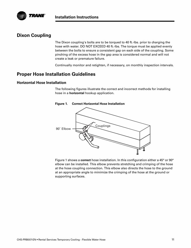
Figure 1. Correct Horizontal Hose Installation
Figure 1 shows a correct hose installation. In this configuration either a 45° or 90° elbow can be installed. This elbow prevents stretching and crimping of the hose at the hose coupling connection. This elbow also directs the hose to the ground at an appropriate angle to minimize the crimping of the hose at the ground or supporting surfaces.
12 Rental Services Temporary Cooling - Flexible Water Hose • CHS-PRB007-EN
Installation Instructions
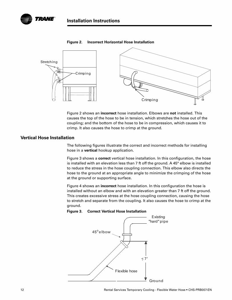
Figure 2. Incorrect Horizontal Hose Installation
Figure 2 shows an incorrect hose installation. Elbows are not installed. This causes the top of the hose to be in tension, which stretches the hose out of the coupling; and the bottom of the hose to be in compression, which causes it to crimp. It also causes the hose to crimp at the ground.
Vertical Hose Installation
The following figures illustrate the correct and incorrect methods for installing hose in a vertical hookup application.
Figure 3 shows a correct vertical hose installation. In this configuration, the hose is installed with an elevation less than 7 ft off the ground. A 45° elbow is installed to reduce the stress in the hose coupling connection. This elbow also directs the hose to the ground at an appropriate angle to minimize the crimping of the hose at the ground or supporting surface.
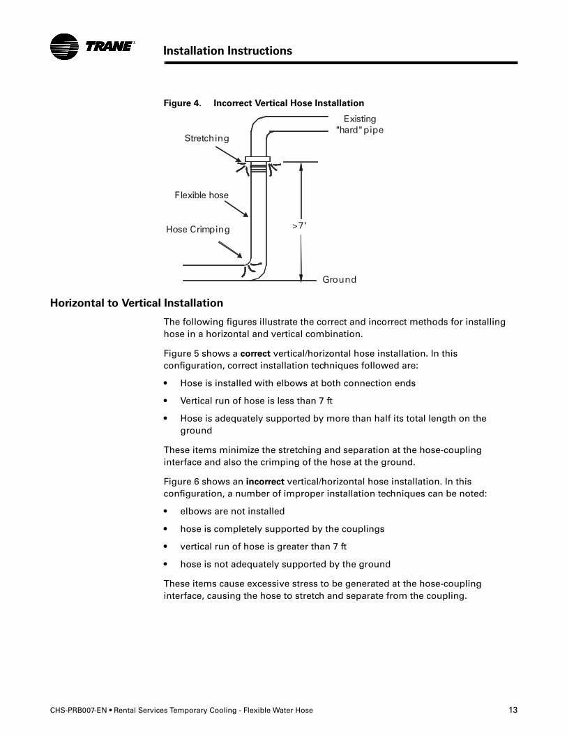
Figure 4 shows an incorrect hose installation. In this configuration the hose is installed without an elbow and with an elevation greater than 7 ft off the ground. This creates excessive stress at the hose coupling connection, causing the hose to stretch and separate from the coupling. It also causes the hose to crimp at the ground.
Figure 3. Correct Vertical Hose Installation
CHS-PRB007-EN • Rental Services Temporary Cooling - Flexible Water Hose 13
Installation Instructions
Figure 4. Incorrect Vertical Hose Installation
Horizontal to Vertical Installation
The following figures illustrate the correct and incorrect methods for installing hose in a horizontal and vertical combination.
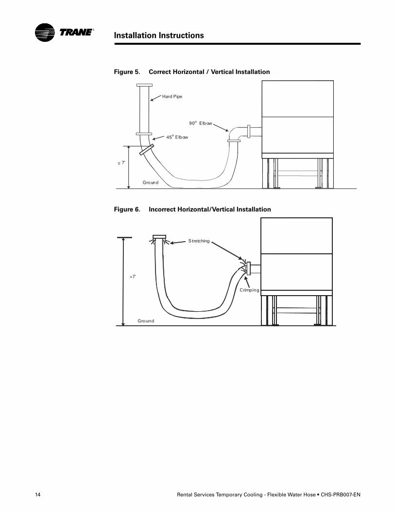
Figure 5 shows a correct vertical/horizontal hose installation. In this configuration, correct installation techniques followed are:
• Hose is installed with elbows at both connection ends
• Vertical run of hose is less than 7 ft
• Hose is adequately supported by more than half its total length on the ground
These items minimize the stretching and separation at the hose-coupling interface and also the crimping of the hose at the ground.
Figure 6 shows an incorrect vertical/horizontal hose installation. In this configuration, a number of improper installation techniques can be noted:
• elbows are not installed
• hose is completely supported by the couplings
• vertical run of hose is greater than 7 ft
• hose is not adequately supported by the ground
These items cause excessive stress to be generated at the hose-coupling interface, causing the hose to stretch and separate from the coupling.
14 Rental Services Temporary Cooling - Flexible Water Hose • CHS-PRB007-EN
Installation Instructions
Figure 5. Correct Horizontal / Vertical Installation
Figure 6. Incorrect Horizontal/Vertical Installation
CHS-PRB007-EN • Rental Services Temporary Cooling - Flexible Water Hose 15
Installation Instructions
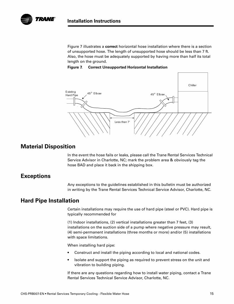
Figure 7 illustrates a correct horizontal hose installation where there is a section of unsupported hose. The length of unsupported hose should be less than 7 ft. Also, the hose must be adequately supported by having more than half its total length on the ground.
Figure 7. Correct Unsupported Horizontal Installation
Material Disposition
In the event the hose fails or leaks, please call the Trane Rental Services Technical Service Advisor in Charlotte, NC; mark the problem area & obviously tag the hose BAD and place it back in the shipping box.
Exceptions
Any exceptions to the guidelines established in this bulletin must be authorized in writing by the Trane Rental Services Technical Service Advisor, Charlotte, NC.
Hard Pipe Installation
Certain installations may require the use of hard pipe (steel or PVC). Hard pipe is typically recommended for
(1) Indoor installations, (2) vertical installations greater than 7 feet, (3) installations on the suction side of a pump where negative pressure may result, (4) semi-permanent installations (three months or more) and/or (5) installations with space limitations.
When installing hard pipe:
• Construct and install the piping according to local and national codes.
• Isolate and support the piping as required to prevent stress on the unit and vibration to building piping.
If there are any questions regarding how to install water piping, contact a Trane Rental Services Technical Service Advisor, Charlotte, NC.
Trane A business of American Standard Companies www.trane.com
For more information, contact your local Trane office or e-mail us at [email protected]
Literature Order Number CHS-PRB007-EN
Date September 2006
Supersedes New
Stocking Location Print-on-Demand
Trane has a policy of continuous product and product data improvement and reserves the right to change design and specifications without notice.