remediation technologies for soils and groundwater || physical treatment technologies
TRANSCRIPT
CHAPTER 3
Physical Treatment Technologies
Ravi Damera and Alok Bhandari
3.1 Introduction
Physical treatment technologies take advantage of physicochemical properties ofthe contaminant and the affected media to remediate soil and groundwater. The mostsignificant physicochemical properties of a contaminant in this context include itsdensity, solubility, viscosity, and volatility. Physical properties of the media that can beexploited during site remediation include the physical state (solid, liquid or gas) of themedia, its bulk density, moisture content, permeability, porosity, particle sizedistribution and ability to conduct heat or electric current. Most conventional physicaltreatment technologies take advantage of the physicochemical properties of both thecontaminant and the media. Such remediation technologies include free productrecovery, pump and treat, soil vapor extraction, air sparging, groundwater circulationwells, multi-phase extraction, induced fracturing and soil heating. This chapter discussesthe application of the above-mentioned physical treatment technologies for soil andgroundwater remediation.
3.2 Free Product Recovery
Free product or free phase represents light nonaqueous phase liquids (LNAPLs)or dense nonaqueous phase liquids (DNAPLs) present in sufficient volumes in thesubsurface to saturate the geologic media and allow flow of the NAPL into recoverywells or excavation trenches. Subpart F of 40 CFR specifies that the corrective action forsites contaminated by petroleum hydrocarbons or hazardous substances should includeremoval and recovery of free product, wherever applicable, to the maximum extentpracticable as determined by the implementing agency. Free product removal should beaccomplished using protocols that minimize the spread of contamination into previouslyuncontaminated zones, and adequately manage the treatment, discharge or disposal ofrecovery byproducts in compliance with applicable regulations. Typically, only about50% of the free phase in the subsurface is recoverable while the rest remains as a
47
Remediation Technologies for Soils and Groundwater
Dow
nloa
ded
from
asc
elib
rary
.org
by
OL
D D
OM
INIO
N U
NIV
ER
SIT
Y o
n 06
/01/
14. C
opyr
ight
ASC
E. F
or p
erso
nal u
se o
nly;
all
righ
ts r
eser
ved.
48 Remediation Technologies for Soils and Groundwater
residual phase that continues to serve as a long-term source of groundwatercontamination.
A free product recovery plan for sites contaminated by petroleum products orother NAPLs should seek answers to the following questions:
• Does sufficient site data exist to evaluate the need for free product recovery?• Is free product recovery necessary, and is the recovery approach consistent
with the comprehensive corrective action plan?
Free product recovery may be necessary when estimates indicate the presence ofhigh volumes (> 200 gallons) of free product. Recovery may also be considered forpermeable aquifers with hydraulic conductivities > 10"3 cm/sec, when thickaccumulations (> 1 foot) are detected in wells, or when the free product is located inproximity of surface water or groundwater (EPA 1996a).
The design of an effective free product recovery system requires a thoroughgeological characterization of affected media including its porosity, permeability,heterogeneity and anisotropy. The effective porosity of the subsurface media can be usedto estimate the total mass of spilled product within the affected volume. Rates ofgroundwater flow and migration of free products can be estimated from the permeabilityof the aquifer. Free products tend to migrate faster in heterogeneous porous media bypreferential flow through the most permeable pathways. Nonaqueous phases in thesubsurface generally move in the direction of groundwater flow. However, theirmigration rates are retarded due to their higher viscosity and the lower relativepermeability of the porous medium. Table 3.1 summarizes key properties of the fluidand geologic media that affect subsurface migration and free product recovery.
The design phase for a free product recovery system is often initiated by seekinganswers to the following questions (EPA 1996a):
• What is the spatial distribution of the free product in the subsurface?• What is the expected mass of free product in the contaminated zone?• What mass/volume of the free product is recoverable?• How quickly/easily can the free product be recovered?
First, the areas where free product accumulations are the greatest are located andthe spatial distribution of the free product pool is mapped out. This can be accomplishedby measuring free product in excavation or test pits, estimating contaminant levels ingeological samples collected from soil borings, or determining free phase thickness inmonitoring wells or well points. Other factors that can affect the delineation of free
Remediation Technologies for Soils and Groundwater
Dow
nloa
ded
from
asc
elib
rary
.org
by
OL
D D
OM
INIO
N U
NIV
ER
SIT
Y o
n 06
/01/
14. C
opyr
ight
ASC
E. F
or p
erso
nal u
se o
nly;
all
righ
ts r
eser
ved.
Remediation Technologies for Soils and Groundwater 49
phase in the subsurface include the duration and volume of release, the depth togroundwater, and the direction of groundwater flow.
An estimate of the volume or mass of the free phase in the subsurface can help inthe selection and performance of a free product recovery system. Volume estimates maybe based on information about release events from inventory records, analysis of NAPLin samples collected from soil borings, and thickness of free product in monitoring wellsor well points. Volume of the free product pool may also be estimated by extrapolatingfrom the free product volume recovered. Recoverable free product may account for only20 to 50% of the total volume originally released. The anticipated free product recoveryrates can be estimated from field tests such as bail down or pumping tests, or usingmultiphase flow analysis.
Table 3.1 Fluid and porous media properties affecting free product migration andrecovery.
Property SignificanceSpecific gravity helps characterize the free phase as a LNAPL orDNAPL. It is also needed to estimate the mass of free product in thesubsurface.Lower viscosity free products are more easily recovered.
Interfacial tension is inversely related to pore size. It determines howeasily a geological media will be wetted with a fluid. It also controls theheight of capillary rise in porous media.
Specific Gravity
Viscosity
Interfacial Tension
Capillary Pressure
Relative Permeability
Wettability
Saturation
Residual Saturation
Free product movement in the subsurface tends to occur where capillarypressures are low. Capillary pressure is inversely related to saturation.
Relative permeability of the geological media controls the mobility ofthe free phase in the subsurface. It is directly proportional to saturation.In binary systems, the permeability of each fluid is reduced due to thepresence of the other.
Most geological material are preferentially wet in the following order:water > free product > airThe degree of saturation controls the mobility of the free phase.Saturation levels are also used to estimate the mass of free and residualproductResidual saturation is the minimum saturation level below whichcontinuous flow of the free product ceases.
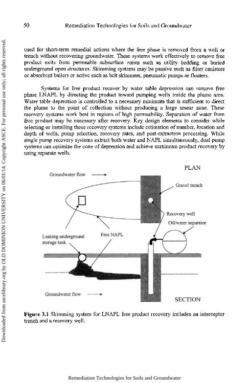
Widely used approaches to recover free product from subsurface contaminantpools include skimming systems, recovery with water table depression, soilvapor/groundwater extraction, and dual phase (liquid and vapor) recovery andseparation. The selection of a particular approach is often guided by site conditions,specific remedial objectives or design constraints. Skimming systems (Figure 3.1) are
Remediation Technologies for Soils and Groundwater
Dow
nloa
ded
from
asc
elib
rary
.org
by
OL
D D
OM
INIO
N U
NIV
ER
SIT
Y o
n 06
/01/
14. C
opyr
ight
ASC
E. F
or p
erso
nal u
se o
nly;
all
righ
ts r
eser
ved.
50 Remediation Technologies for Soils and Groundwater
used for short-term remedial actions where the free phase is removed from a well ortrench without recovering groundwater. These systems work effectively to remove freeproduct exits from permeable subsurface zones such as utility bedding or buriedunderground open structures. Skimming systems may be passive such as filter canistersor absorbent bailers or active such as belt skimmers, pneumatic pumps or floaters.
Systems for free product recover by water table depression can remove freephase LNAPL by directing the product toward pumping wells inside the plume area.Water table depression is controlled to a necessary minimum that is sufficient to directthe plume to the point of collection without producing a large smear zone. Theserecovery systems work best in regions of high permeability. Separation of water fromfree product may be necessary after recovery. Key design elements to consider whileselecting or installing these recovery systems include estimation of number, location anddepth of wells, pump selection, recovery rates, and post-extraction processing. Whilesingle pump recovery systems extract both water and NAPL simultaneously, dual pumpsystems can optimize the cone of depression and achieve maximum product recovery byusing separate wells.
Figure 3.1 Skimming system for LNAPL free product recovery includes an interceptortrench and a recovery well.
Remediation Technologies for Soils and Groundwater
Dow
nloa
ded
from
asc
elib
rary
.org
by
OL
D D
OM
INIO
N U
NIV
ER
SIT
Y o
n 06
/01/
14. C
opyr
ight
ASC
E. F
or p
erso
nal u
se o
nly;
all
righ
ts r
eser
ved.
Remediation Technologies for Soils and Groundwater 51
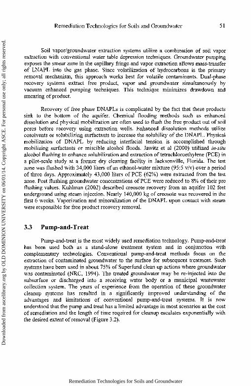
Soil vapor/groundwater extraction systems utilize a combination of soil vaporextraction with conventional water table depression techniques. Groundwater pumpingexposes the smear zone in the capillary fringe and vapor extraction allows mass-transferof LNAPL into the gas phase. Since volatilization of hydrocarbons is the primaryremoval mechanism, this approach works best for volatile contaminants. Dual-phaserecovery systems extract free product, vapor and groundwater simultaneously byvacuum enhanced pumping techniques. This technique minimizes drawdown andsmearing of product.
Recovery of free phase DNAPLs is complicated by the fact that these productssink to the bottom of the aquifer. Chemical flooding methods such as enhanceddissolution and physical mobilization are often used to flush the free product out of soilpores before recovery using extraction wells. Enhanced dissolution methods utilizecosolvents or solubilizing surfactants to increase the solubility of the DNAPL. Physicalmobilization of DNAPL by reducing interfacial tension is accomplished throughmobilizing surfactants or miscible alcohol floods. Jawitz et al (2000) utilized in-situalcohol flushing to enhance solubilization and extraction of tetrachloroethylene (PCE) ina pilot-scale study at a former dry cleaning facility in Jacksonville, Florida. The testzone was flushed with 34,000 liters of an ethanol-water mixture (95:5 v/v) over a periodof three days. Approximately 43,000 liters of PCE (62%) were extracted from the testzone. Post flushing groundwater concentrations of PCE were reduced to 8% of their preflushing values. Kuhlman (2002) described creosote recovery from an aquifer 102 feetunderground using steam injection. Nearly 140,000 kg of creosote was recovered in thefirst 6 weeks. Vaporization and mineralization of the DNAPL upon contact with steamwere responsible for free product recovery removal.
3.3 Pump-and-Treat
Pump-and-treat is the most widely used remediation technology. Pump-and-treathas been used both as a stand-alone treatment system and in conjunction withcomplementary technologies. Conventional pump-and-treat methods focus on theextraction of contaminated groundwater to the surface for subsequent treatment. Suchsystems have been used in about 75% of Superfund clean up actions where groundwaterwas contaminated (NRC, 1994). The treated groundwater may be re-injected into thesubsurface or discharged into a receiving water body or a municipal wastewatercollection system. The years of experience from the operation of these groundwatercleanup systems has resulted in a significantly improved understanding of theadvantages and limitations of conventional pump-and-treat systems. It is nowunderstood that the pump and treat has a limited advantage in most scenarios as the costof remediation and the length of time required for cleanup escalates exponentially withthe desired extent of removal (Figure 3.2).
Remediation Technologies for Soils and Groundwater
Dow
nloa
ded
from
asc
elib
rary
.org
by
OL
D D
OM
INIO
N U
NIV
ER
SIT
Y o
n 06
/01/
14. C
opyr
ight
ASC
E. F
or p
erso
nal u
se o
nly;
all
righ
ts r
eser
ved.

52 Remediation Technologies for Soils and Groundwater
Figure 3.2 Impact of desired extent of cleanup on the relative cost and duration of aconventional pump-and-treat remedial action (NRC, 1994).
Nevertheless, pump-and-treat systems continue to constitute essentialcomponents of most modern groundwater remediation efforts. An important designobjective of a groundwater extraction system may be the hydraulic control ofgroundwater to prevent offsite migration of the contaminant plume during restorationefforts. Properly located extraction wells can remove water from the aquifer by creatinga capture zone for migrating contaminants. As water is extracted, a capture zone curvesdevelops upstream of the well. Groundwater inside the capture zone is extracted by thewell while that outside is not. In its simplest form, the envelope surrounding a capturezone curve may be defined by the following equation (Javandel and Tsang, 1986):
where, x andy are the coordinates describing the envelope (Figure 3.3), B is the aquiferthickness (m), v is the Darcy velocity and Q is the well pumping rate (m3/day).
The aquifer is assumed to be homogeneous, isotropic, uniform in cross-section,infinite in width, and with an insignificant drawdown compared to the aquifer thickness.For this simple analysis, the extraction well is assumed to extend through the entirethickness of the aquifer and is screened to extract uniformly at every level. As seen fromFigure 3.3 and Eq. 3.1, at large values of x, the ordinate, y is equal to Q/2Bv, and thewidth of the capture zone envelope is, Q/Bv. Similarly, the width of the capture zonealong the y-axis, where x = 0 is Q/2Bv. A general equation for the positive half of the
Remediation Technologies for Soils and Groundwater
Dow
nloa
ded
from
asc
elib
rary
.org
by
OL
D D
OM
INIO
N U
NIV
ER
SIT
Y o
n 06
/01/
14. C
opyr
ight
ASC
E. F
or p
erso
nal u
se o
nly;
all
righ
ts r
eser
ved.

Remediation Technologies for Soils and Groundwater 53
capture zone curve for n equally placed wells along the y-axis and arrangedsymmetrically across the x-axis is given by (Masters, 1996):
where 0t is the angle in radians between a horizontal line and through the fh well and apoint on the capture zone envelope.
Once groundwater is extracted, a variety of physical, chemical and biologicalprocesses can be used to treat the contaminated water. These processes includeadsorption, volatilization, precipitation, oxidation-reduction, and biotransformation andare discussed elsewhere in this text. However, the effective extraction of contaminatedgroundwater at the site requires that the contaminant sources be identified, located, andcontrolled. Wherever possible, source removal should be implemented to prevent furthercontamination. A thorough study of the site should include assessing the type and extentof contamination and a three-dimensional characterization of the subsurface includinghydraulic conductivity, particle size distribution and the sorption potential of aquifermaterial. Such a characterization may help estimate realistic cleanup goals by classifyingthe site according to the National Research Council's criteria described in Table 3.2. Forpump-and-treat systems to work effectively, the system should be managed dynamicallyonsite utilizing continuously updated site-specific information such as extraction rates,water levels in monitoring wells and contaminant concentrations in observation wells(EPA 1996b).
Figure 3.3 Two-dimensional capture zone envelope for a well extending the entire depthof an aquifer and pumping at a constant rate to extract groundwater equally at all levels.
Remediation Technologies for Soils and Groundwater
Dow
nloa
ded
from
asc
elib
rary
.org
by
OL
D D
OM
INIO
N U
NIV
ER
SIT
Y o
n 06
/01/
14. C
opyr
ight
ASC
E. F
or p
erso
nal u
se o
nly;
all
righ
ts r
eser
ved.
54 Remediation Technologies for Soils and Groundwater
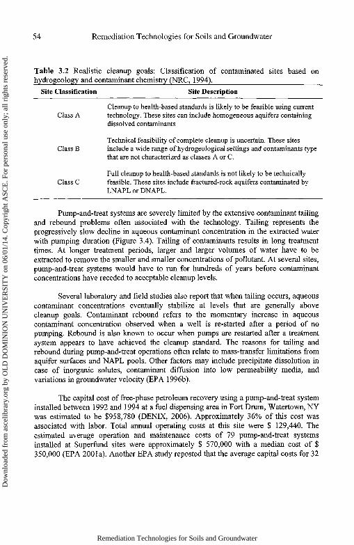
Table 3.2 Realistic cleanup goals: Classification of contaminated sites based onhydrogeology and contaminant chemistry (NRC, 1994).
Site Classification Site Description
Cleanup to health-based standards is likely to be feasible using currentClass A technology. These sites can include homogeneous aquifers containing
dissolved contaminants
Technical feasibility of complete cleanup is uncertain. These sitesClass B include a wide range of hydrogeological settings and contaminants type
that are not characterized as classes A or C.
Full cleanup to health-based standards is not likely to be technicallyClass C feasible. These sites include fractured-rock aquifers contaminated by
LNAPL or DNAPL.
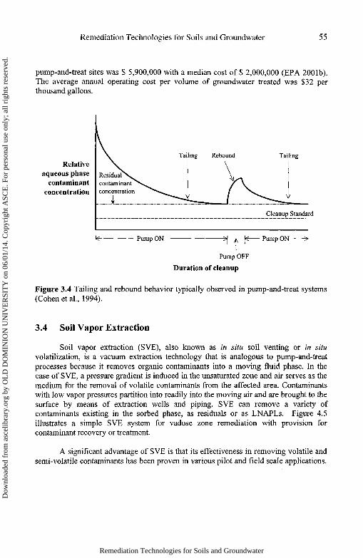
Pump-and-treat systems are severely limited by the extensive contaminant tailingand rebound problems often associated with the technology. Tailing represents theprogressively slow decline in aqueous contaminant concentration in the extracted waterwith pumping duration (Figure 3.4). Tailing of contaminants results in long treatmenttimes. At longer treatment periods, larger and larger volumes of water have to beextracted to remove the smaller and smaller concentrations of pollutant. At several sites,pump-and-treat systems would have to run for hundreds of years before contaminantconcentrations have receded to acceptable cleanup levels.
Several laboratory and field studies also report that when tailing occurs, aqueouscontaminant concentrations eventually stabilize at levels that are generally abovecleanup goals. Contaminant rebound refers to the momentary increase in aqueouscontaminant concentration observed when a well is re-started after a period of nopumping. Rebound is also known to occur when pumps are restarted after a treatmentsystem appears to have achieved the cleanup standard. The reasons for tailing andrebound during pump-and-treat operations often relate to mass-transfer limitations fromaquifer surfaces and NAPL pools. Other factors may include precipitate dissolution incase of inorganic solutes, contaminant diffusion into low permeability media, andvariations in groundwater velocity (EPA 1996b).
The capital cost of free-phase petroleum recovery using a pump-and-treat systeminstalled between 1992 and 1994 at a fuel dispensing area in Fort Drum, Watertown, NYwas estimated to be $958,780 (DENIX, 2006). Approximately 36% of this cost wasassociated with labor. Total annual operating costs at this site were $ 129,440. Theestimated average operation and maintenance costs of 79 pump-and-treat systemsinstalled at Superftmd sites were approximately $ 570,000 with a median cost of $350,000 (EPA 200la). Another EPA study reposted that the average capital costs for 32
Remediation Technologies for Soils and Groundwater
Dow
nloa
ded
from
asc
elib
rary
.org
by
OL
D D
OM
INIO
N U
NIV
ER
SIT
Y o
n 06
/01/
14. C
opyr
ight
ASC
E. F
or p
erso
nal u
se o
nly;
all
righ
ts r
eser
ved.
Remediation Technologies for Soils and Groundwater 55
pump-and-treat sites was $ 5,900,000 with a median cost of $ 2,000,000 (EPA 2001b).The average annual operating cost per volume of groundwater treated was $32 perthousand gallons.
Duration of cleanup
Figure 3.4 Tailing and rebound behavior typically observed in pump-and-treat systems(Cohen et al., 1994).
3.4 Soil Vapor Extraction
Soil vapor extraction (SVE), also known as in situ soil venting or in situvolatilization, is a vacuum extraction technology that is analogous to pump-and-treatprocesses because it removes organic contaminants into a moving fluid phase. In thecase of SVE, a pressure gradient is induced in the unsaturated zone and air serves as themedium for the removal of volatile contaminants from the affected area. Contaminantswith low vapor pressures partition into readily into the moving air and are brought to thesurface by means of extraction wells and piping. SVE can remove a variety ofcontaminants existing in the sorbed phase, as residuals or as LNAPLs. Figure 4.5illustrates a simple SVE system for vadose zone remediation with provision forcontaminant recovery or treatment.
A significant advantage of SVE is that its effectiveness in removing volatile andsemi-volatile contaminants has been proven in various pilot and field scale applications.
Remediation Technologies for Soils and Groundwater
Dow
nloa
ded
from
asc
elib
rary
.org
by
OL
D D
OM
INIO
N U
NIV
ER
SIT
Y o
n 06
/01/
14. C
opyr
ight
ASC
E. F
or p
erso
nal u
se o
nly;
all
righ
ts r
eser
ved.

56 Remediation Technologies for Soils and Groundwater
Table 3.3 presents a summary of advantages and limitations of SVE. It is recommendedthat the feasibility of SVE at a particular site be assessed by a detailed assessment of thesite and contaminant characteristics, the SVE system design, and the operating andmonitoring requirements.
Table 3.3 Advantages and limitations of soil vapor extraction systems (EPA, 2002).Advantages Limitations
Proven technology, demonstrated experience
Minimal site disturbance
Effective at hard to access sites, e.g., underbuildings
Relatively short treatment times
Efficient and cost-effective
Can be combined with other technologies
Air emission permits may be required
On site containment or treatment of extractedvapors necessary
Effective for unsaturated zones only
Not very effective in clayey or lowpermeability soils
High (> 90%) contaminant removalefficiencies unachievable
Lack of guidelines for optimal design,installation and operation
The vapor pressure is the most relevant contaminant property controlling itsremoval effectiveness by SVE. Generally, solutes with vapor pressures higher than 65Pa (0.5 mm of Hg) or Henry's Law constants greater than 10,000 kPa (100 atm) can besuccessfully removed by SVE. These contaminants include chemicals such as BTEX,and naphthalene. In the case of petroleum hydrocarbons, gasoline, kerosene and dieselcomponents with boiling points less than 300°C can be removed by vapor extraction.
Soil and vadose zone properties of significance for SVE systems includemoisture content, groundwater depth, permeability, soil structure, and stratification. Thepresence of soil water in the unsaturated zone can reduce the effectiveness of SVE bypreventing the flow of air through the contaminated area. Fine-grained soils producethicker capillary fringes that can also reduce the effectiveness of SVE. Contaminatedzones that are affected by groundwater fluctuations are more difficult to treat by vaporextraction. SVE is most effective at sites with groundwater tables greater than 3 metersdeep but may also be implemented at sites with shallower water tables. Vacuumextraction is not applicable at sites with groundwater surfaces less than 1 meter deep.SVE holds great promise in soils with low moisture contents and intrinsic permeabilityvalues greater than 10"10 cm2. A fractured soil may manifest high permeability due topreferential flow paths for the air but result in ineffective or slow treatment of theunfractured media. Similarly, stratification of soils with different permeabilities can alsoresult in non-uniform remediation of the contaminated site.
Remediation Technologies for Soils and Groundwater
Dow
nloa
ded
from
asc
elib
rary
.org
by
OL
D D
OM
INIO
N U
NIV
ER
SIT
Y o
n 06
/01/
14. C
opyr
ight
ASC
E. F
or p
erso
nal u
se o
nly;
all
righ
ts r
eser
ved.
Remediation Technologies for Soils and Groundwater 57
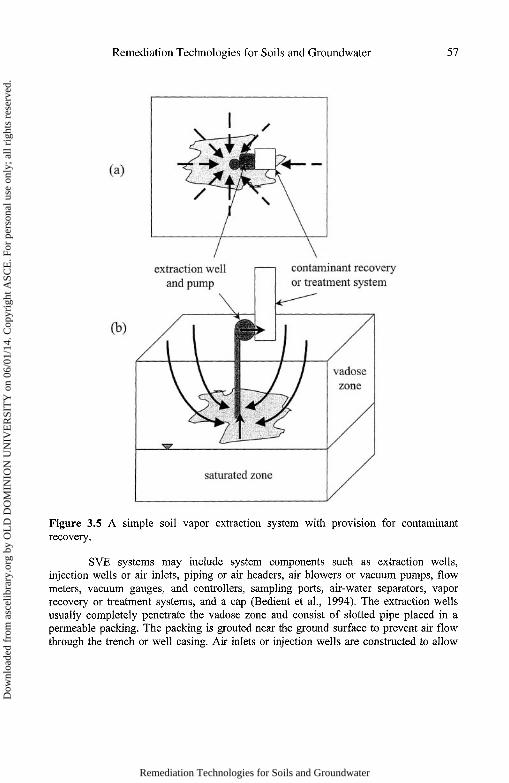
Figure 3.5 A simple soil vapor extraction system with provision for contaminantrecovery.
SVE systems may include system components such as extraction wells,injection wells or air inlets, piping or air headers, air blowers or vacuum pumps, flowmeters, vacuum gauges, and controllers, sampling ports, air-water separators, vaporrecovery or treatment systems, and a cap (Bedient et al., 1994). The extraction wellsusually completely penetrate the vadose zone and consist of slotted pipe placed in apermeable packing. The packing is grouted near the ground surface to prevent air flowthrough the trench or well casing. Air inlets or injection wells are constructed to allow
Remediation Technologies for Soils and Groundwater
Dow
nloa
ded
from
asc
elib
rary
.org
by
OL
D D
OM
INIO
N U
NIV
ER
SIT
Y o
n 06
/01/
14. C
opyr
ight
ASC
E. F
or p
erso
nal u
se o
nly;
all
righ
ts r
eser
ved.
58 Remediation Technologies for Soils and Groundwater
air to be drawn into the vadose zone at the desired locations. These componentsstrategically direct the flow of air to obtain optimal contaminant removals.
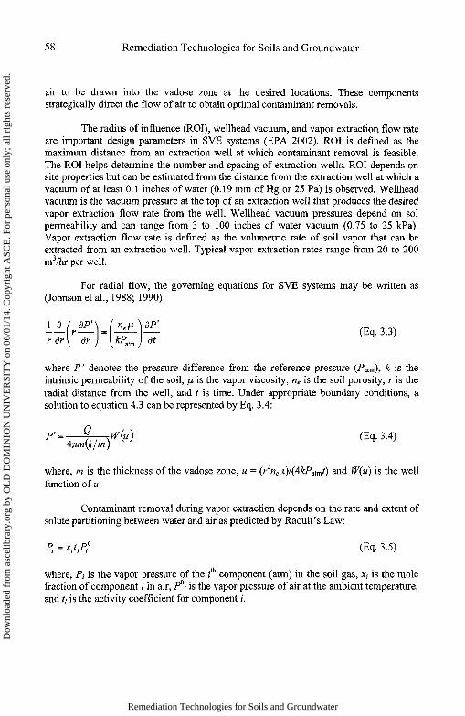
The radius of influence (ROI), wellhead vacuum, and vapor extraction flow rateare important design parameters in SVE systems (EPA 2002). ROI is defined as themaximum distance from an extraction well at which contaminant removal is feasible.The ROI helps determine the number and spacing of extraction wells. ROI depends onsite properties but can be estimated from the distance from the extraction well at which avacuum of at least 0.1 inches of water (0.19 mm of Hg or 25 Pa) is observed. Wellheadvacuum is the vacuum pressure at the top of an extraction well that produces the desiredvapor extraction flow rate from the well. Wellhead vacuum pressures depend on solpermeability and can range from 3 to 100 inches of water vacuum (0.75 to 25 kPa).Vapor extraction flow rate is defined as the volumetric rate of soil vapor that can beextracted from an extraction well. Typical vapor extraction rates range from 20 to 200m3/hr per well.
For radial flow, the governing equations for SVE systems may be written as(Johnson etal., 1988; 1990)
where P' denotes the pressure difference from the reference pressure (Patm), k is theintrinsic permeability of the soil, \JL is the vapor viscosity, ne is the soil porosity, r is theradial distance from the well, and t is time. Under appropriate boundary conditions, asolution to equation 4.3 can be represented by Eq. 3.4:
where, m is the thickness of the vadose zone, u = (r2ne[jC)/(4kPaimf) and W(u) is the wellfunction of w.
Contaminant removal during vapor extraction depends on the rate and extent ofsolute partitioning between water and air as predicted by Raoult's Law:
where, P, is the vapor pressure of the zth component (atm) in the soil gas, xt is the molefraction of component i in air, P°, is the vapor pressure of air at the ambient temperature,and ti is the activity coefficient for component i.
Remediation Technologies for Soils and Groundwater
Dow
nloa
ded
from
asc
elib
rary
.org
by
OL
D D
OM
INIO
N U
NIV
ER
SIT
Y o
n 06
/01/
14. C
opyr
ight
ASC
E. F
or p
erso
nal u
se o
nly;
all
righ
ts r
eser
ved.

Remediation Technologies for Soils and Groundwater 59
The costs associated with installing and operating a SVE system are specific to acontaminated site. These costs depend on the types of contaminants, extent and durationof contamination, and characteristics of the affected media. The most important designcomponents that impact the cost of an SVE system include the number and depths ofinstalled wells, level of vacuum required, capacity of blowers, type of off-gas and watertreatment, and the anticipated duration of operation.
A full-scale SVE system was used to clean up 13,500 m3 of sandy soil at CampLeJeune, North Carolina (EPA, 1999). The soil had been contaminated with volatileorganic chemicals (VOCs) including TCE, PCE and benzene. The air-permeability atthis site ranged between 1.2 and 2.8 x 10"7 cm2. The SVE system included eight verticalextraction wells that penetrated 15 to 16 feet below surface and a horizontal well forinjection of air. The vacuum extraction unit consisted of a positive displacement blower(42.5 m3/min at 0.5 atm vacuum). The unit also consisted of a vapor-liquid separator, aliquid transfer pump, a silencer, particulate filters, a discharge stack and a control panel.The SVE system also consisted of 32 soil probe clusters to measure soil vaporconcentrations of the contaminants. Each cluster was comprised of a shallow and deepprobe installed 6 feet and 12 feet below surface, respectively. While flow rates atindividual well-heads ranged between 0.62 and 3.74 m3 at 0.1 to 0.23 atm of vacuum,the total flow rate in the SVE system averaged 11.6 m3 at 0.19 atm of vacuum. Thecapital cost associated with this SVE system was $222,455, and the operation andmaintenance costs were $247,485. This averaged treatment cost was $35/m3 of soiltreated.
3.5 Air Sparging
Air sparging, also known as in-situ air stripping or in situ volatilization, is usedin conjunction with SVE to remove volatile contaminants from the saturated zone. Inthis case, the air is injected into the saturated zone at a point below the affected area inthe aquifer (Figure 3.6). Air bubbles rise within an inverted-cone zone through thecontaminated water and strip the aqueous contaminants into the gas phase. The vaporextraction system then removes the air and contaminants from the soil. A contaminantrecovery or treatment system can be used to manage the extracted contaminants.
Air sparging systems have found the widest use in the treatment of petroleumcontaminated capillary fringe zones and dissolved plumes resulting from leakingunderground storage tanks (Leeson et al., 2002). Table 3.4 summarizes the keyadvantages and limitations of this technology. Factors that can impact the effectivenessof air sparging at a particular site include soil heterogeneity, air flow regime, depth ofcontamination, and contaminant characteristics. Soils with low intrinsic permeability aredifficult to treat by air sparging and soil heterogeneity can prevent the uniform
Remediation Technologies for Soils and Groundwater
Dow
nloa
ded
from
asc
elib
rary
.org
by
OL
D D
OM
INIO
N U
NIV
ER
SIT
Y o
n 06
/01/
14. C
opyr
ight
ASC
E. F
or p
erso
nal u
se o
nly;
all
righ
ts r
eser
ved.

60 Remediation Technologies for Soils and Groundwater
distribution of air. Non-uniform flow of air may also lead to uncontrolled migration ofcontaminants. Contaminants with low Henry's Law constants may be difficult to stripfrom the aqueous phase. The low number of field implementations of air sparging meansthat design, installation and operation have been largely empirical.
Figure 3.6 Air sparging system with vapor extraction.
The feasibility of air sparging as a treatment technology for a contaminated sitecan be assessed by a four step process (EPA 2002): (1) initial screening of air spargingeffectiveness; (2) detailed investigation of air sparging effectiveness; (3) evaluation ofair sparging system design; and (4) evaluation of operation and monitoring plans. Theinitial screening comprises of determination of the existence of free product at the site,evaluation of soil permeability, an analysis of the types of contaminants present, and aninvestigation of nearby underground structures. A follow-up detailed investigation isconducted by determining the exact composition and concentration of the contaminantsand evaluating the Henry's Law constants, boiling points, vapor pressures, solubility,and phase partitioning behavior of individual components. This second step alsoinvolves a more thorough characterization of the subsurface including determining theintrinsic permeability, soil structure and stratification. The concentrations of dissolvediron (Fe2+) and manganese (Mn2+) in groundwater are measured. These metals can be
Remediation Technologies for Soils and Groundwater
Dow
nloa
ded
from
asc
elib
rary
.org
by
OL
D D
OM
INIO
N U
NIV
ER
SIT
Y o
n 06
/01/
14. C
opyr
ight
ASC
E. F
or p
erso
nal u
se o
nly;
all
righ
ts r
eser
ved.
Remediation Technologies for Soils and Groundwater 61
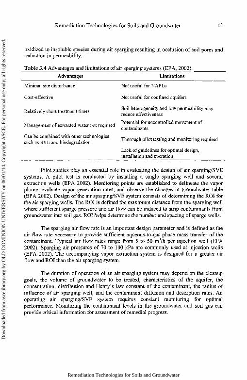
oxidized to insoluble species during air sparging resulting in occlusion of soil pores andreduction in permeability.
Table 3.4 Advantages and limitations of air sparging systems (EPA, 2002).Advantages Limitations
Minimal site disturbance
Cost-effective
Relatively short treatment times
Management of extracted water not required
Can be combined with other technologiessuch as SVE and biodegradation
Not useful for NAPLs
Not useful for confined aquifers
Soil heterogeneity and low permeability mayreduce effectiveness
Potential for uncontrolled movement ofcontaminants
Thorough pilot testing and monitoring required
Lack of guidelines for optimal design,installation and operation
Pilot studies play an essential role in evaluating the design of air sparging/SVEsystems. A pilot test is conducted by installing a single sparging well and severalextraction wells (EPA 2002). Monitoring points are established to delineate the vaporplume, evaluate vapor generation rates, and observe the changes in groundwater table(EPA 2002). Design of the air sparging/SVE system consists of determining the ROI forthe air sparging wells. The ROI is defined the maximum distance from the sparging wellwhere sufficient sparge pressure and air flow can be induced to strip contaminants fromgroundwater into soil gas. ROI helps determine the number and spacing of sparge wells.
The sparging air flow rate is an important design parameter and is defined as theair flow rate necessary to provide sufficient aqueous-to-gas phase mass transfer of thecontaminant. Typical air flow rates range from 5 to 50 m3/h per injection well (EPA2002). Sparging air pressures of 70 to 100 kPa are commonly used at injection wells(EPA 2002). The accompanying vapor extraction system is designed for a greater airflow and ROI than the air sparging system.
The duration of operation of an air sparging system may depend on the cleanupgoals, the volume of groundwater to be treated, characteristics of the aquifer, theconcentration, distribution and Henry's law constant of the contaminant, the radius ofinfluence of air sparging well, and the contaminant diffusion and desorption rates. Anoperating air sparging/SVE system requires constant monitoring for optimalperformance. Monitoring the contaminant levels in the groundwater and soil gas canprovide critical information for assessment of remedial progress.
Remediation Technologies for Soils and Groundwater
Dow
nloa
ded
from
asc
elib
rary
.org
by
OL
D D
OM
INIO
N U
NIV
ER
SIT
Y o
n 06
/01/
14. C
opyr
ight
ASC
E. F
or p
erso
nal u
se o
nly;
all
righ
ts r
eser
ved.
62 Remediation Technologies for Soils and Groundwater
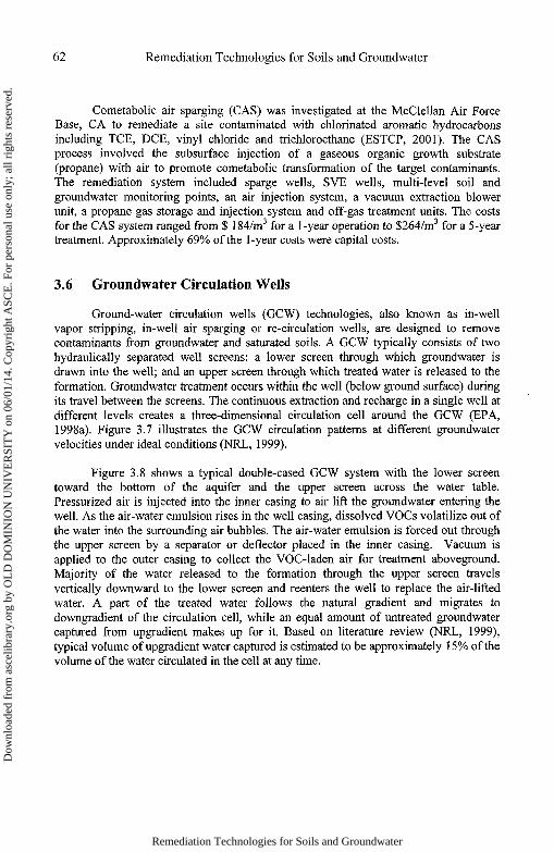
Cometabolic air sparging (CAS) was investigated at the McClellan Air ForceBase, CA to remediate a site contaminated with chlorinated aromatic hydrocarbonsincluding TCE, DCE, vinyl chloride and trichloroethane (ESTCP, 2001). The CASprocess involved the subsurface injection of a gaseous organic growth substrate(propane) with air to promote cometabolic transformation of the target contaminants.The remediation system included sparge wells, SVE wells, multi-level soil andgroundwater monitoring points, an air injection system, a vacuum extraction blowerunit, a propane gas storage and injection system and off-gas treatment units. The costsfor the CAS system ranged from $ 184/m3 for a 1-year operation to $264/m3 for a 5-yeartreatment. Approximately 69% of the 1-year costs were capital costs.
3.6 Groundwater Circulation Wells
Ground-water circulation wells (GCW) technologies, also known as in-wellvapor stripping, in-well air sparging or re-circulation wells, are designed to removecontaminants from groundwater and saturated soils. A GCW typically consists of twohydraulically separated well screens: a lower screen through which groundwater isdrawn into the well; and an upper screen through which treated water is released to theformation. Groundwater treatment occurs within the well (below ground surface) duringits travel between the screens. The continuous extraction and recharge in a single well atdifferent levels creates a three-dimensional circulation cell around the GCW (EPA,1998a). Figure 3.7 illustrates the GCW circulation patterns at different groundwatervelocities under ideal conditions (NRL, 1999).
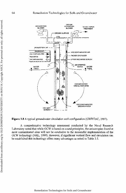
Figure 3.8 shows a typical double-cased GCW system with the lower screentoward the bottom of the aquifer and the upper screen across the water table.Pressurized air is injected into the inner casing to air lift the groundwater entering thewell. As the air-water emulsion rises in the well casing, dissolved VOCs volatilize out ofthe water into the surrounding air bubbles. The air-water emulsion is forced out throughthe upper screen by a separator or deflector placed in the inner casing. Vacuum isapplied to the outer casing to collect the VOC-laden air for treatment aboveground.Majority of the water released to the formation through the upper screen travelsvertically downward to the lower screen and reenters the well to replace the air-liftedwater. A part of the treated water follows the natural gradient and migrates todowngradient of the circulation cell, while an equal amount of untreated groundwatercaptured from upgradient makes up for it. Based on literature review (NRL, 1999),typical volume of upgradient water captured is estimated to be approximately 15% of thevolume of the water circulated in the cell at any time.
Remediation Technologies for Soils and Groundwater
Dow
nloa
ded
from
asc
elib
rary
.org
by
OL
D D
OM
INIO
N U
NIV
ER
SIT
Y o
n 06
/01/
14. C
opyr
ight
ASC
E. F
or p
erso
nal u
se o
nly;
all
righ
ts r
eser
ved.
Remediation Technologies for Soils and Groundwater 63
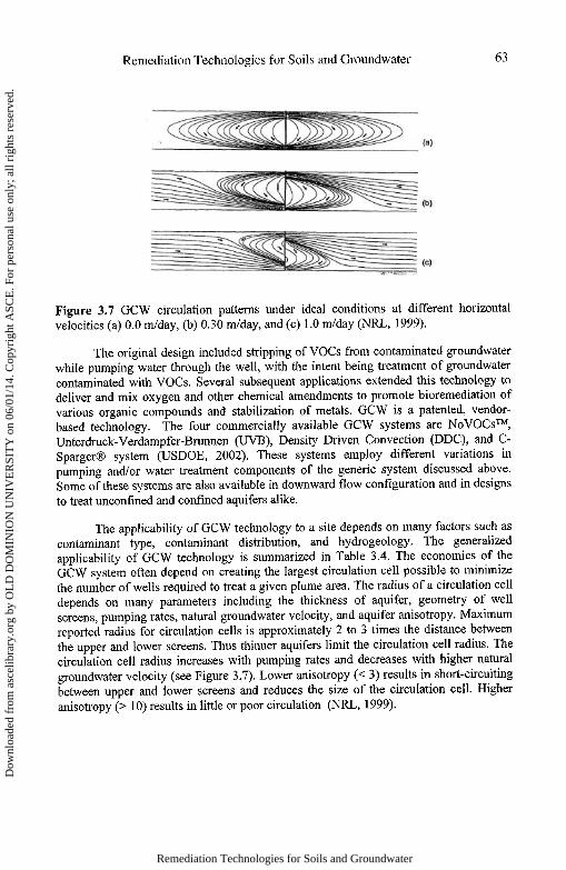
Figure 3.7 GCW circulation patterns under ideal conditions at different horizontalvelocities (a) 0.0 m/day, (b) 0.30 m/day, and (c) 1.0 m/day (NRL, 1999).
The original design included stripping of VOCs from contaminated groundwaterwhile pumping water through the well, with the intent being treatment of groundwatercontaminated with VOCs. Several subsequent applications extended this technology todeliver and mix oxygen and other chemical amendments to promote bioremediation ofvarious organic compounds and stabilization of metals. GCW is a patented, vendor-based technology. The four commercially available GCW systems are No VOCs™,Unterdruck-Verdampfer-Brunnen (UVB), Density Driven Convection (DDC), and C-Sparger® system (USDOE, 2002). These systems employ different variations inpumping and/or water treatment components of the generic system discussed above.Some of these systems are also available in downward flow configuration and in designsto treat unconfmed and confined aquifers alike.
The applicability of GCW technology to a site depends on many factors such ascontaminant type, contaminant distribution, and hydrogeology. The generalizedapplicability of GCW technology is summarized in Table 3.4. The economics of theGCW system often depend on creating the largest circulation cell possible to minimizethe number of wells required to treat a given plume area. The radius of a circulation celldepends on many parameters including the thickness of aquifer, geometry of wellscreens, pumping rates, natural groundwater velocity, and aquifer anisotropy. Maximumreported radius for circulation cells is approximately 2 to 3 times the distance betweenthe upper and lower screens. Thus thinner aquifers limit the circulation cell radius. Thecirculation cell radius increases with pumping rates and decreases with higher naturalgroundwater velocity (see Figure 3.7). Lower anisotropy (< 3) results in short-circuitingbetween upper and lower screens and reduces the size of the circulation cell. Higheranisotropy (> 10) results in little or poor circulation (NRL, 1999).
Remediation Technologies for Soils and Groundwater
Dow
nloa
ded
from
asc
elib
rary
.org
by
OL
D D
OM
INIO
N U
NIV
ER
SIT
Y o
n 06
/01/
14. C
opyr
ight
ASC
E. F
or p
erso
nal u
se o
nly;
all
righ
ts r
eser
ved.
64 Remediation Technologies for Soils and Groundwater
Figure 3.8 A typical groundwater circulation well configuration (GWRTAC, 1997).
A comprehensive technology assessment conducted by the Naval ResearchLaboratory noted that while GCW is based on sound principles, the anisotropies found atmost contaminated sites will not be conducive to the successful implementation of theGCW technology (NRL, 1999). However, if significant vertical flow and circulation canbe established this technology offers many advantages as noted in Table 3.5.
Remediation Technologies for Soils and Groundwater
Dow
nloa
ded
from
asc
elib
rary
.org
by
OL
D D
OM
INIO
N U
NIV
ER
SIT
Y o
n 06
/01/
14. C
opyr
ight
ASC
E. F
or p
erso
nal u
se o
nly;
all
righ
ts r
eser
ved.

Remediation Technologies for Soils and Groundwater 65
Table 3.4 General applicability of GCW technology (NRL, 1999).Parameter ApplicabilityContaminant Type
VOCs XXXSVOCs XXXMetals XXRadionuclides X
Cleanup StrategySource Treatment XXXPlume Reduction XXPlume Interception XX
Unsaturated Thickness0 - 5 f t X5-1,000 ft
Saturated Thickness0 - 5 f t X5-115N FT> 115 FT
Aquifer CharacteristicsPorous Media XXFractured Media XKarst XBackground Flow Velocity
Low (< 0.00Ift/d) XXXModerate (0.001 - l.Oft/d) XXHigh(>1.0ft/d) X
Horizontal Hydraulic ConductivityModerate (0.03 ~ l.Oft/d) XHigh(>lft/d) X
Anisotropy RatioAnisotropic (3 - 10) XXHighly Anisotropic (>10) X
Aquifer ChemistryHigh Fe in Water XHigh Ca/Mg in water X
XXX - Good potential for success; XX - Moderate potential; X - Limited/no potential
The U.S. Army Corps of Engineers conducted a pilot investigation of a GCW atthe Nebraska Ordnance Plant, Mead NE (EPA 200Ic). The dual GCW system includedan in-well air stripper to treat groundwater containing TCE and UV technology to treatgroundwater containing cyclotrimethylene trinitramme (RDX). The pilot scale systemdemonstrated contaminant mass removal rates of > 96%. The air stripping componentused a 12 inch well to remove groundwater from 60 to 70 feet below surface. TCE
XX
XXX
XXX
XXX
XX
X
Remediation Technologies for Soils and Groundwater
Dow
nloa
ded
from
asc
elib
rary
.org
by
OL
D D
OM
INIO
N U
NIV
ER
SIT
Y o
n 06
/01/
14. C
opyr
ight
ASC
E. F
or p
erso
nal u
se o
nly;
all
righ
ts r
eser
ved.

66 Remediation Technologies for Soils and Groundwater
concentrations were observed dropped from 7,000 ppb to 110 ppb after a single passthrough the air stripper. The UV system used a 6 inch well to extract groundwater whichpassed a UV contactor. RDX concentrations reduced from 70 ppb to below detection inthe recharge zone of the well. Full-scale treatment costs for the GCW system weresimilar to pump-and-treat at $1,900,000, but annual operation and maintenance costswere nearly half at $44,000.
Table 3.5 Advantages and Limitations of GCW (USDOE, 2002).Advantages Limitations
Minimal aboveground space needs, waterhandling, or water discharge
Vertical groundwater flow facilitates flushingof contaminants from source zones
Reduced permitting requirements
Low impact on groundwater levels facilitatingits use near sensitive environments such aswetlands
Less aboveground treatment and resultingprocess wastes
Depth-dependent operational costs are limitedcompared to pump-and-treat
Increase in dissolved oxygen concentrationpromotes aerobic biodegradation
Facilitate reagent delivery and compatible withother technologies such as S VE
High anisotropies reduce the effectiveness ofcirculationUnaccounted vadose zone flushing maymobilize and spread contaminants beyondtreatment zoneCo-current air stripping process generallyused in GCW is not an efficient treatmentprocess
Potential for well fouling due to possiblegeochemical changes
Ineffective sealing between influent andeffluent screens may cause short circuiting
Application of GCW to thin treatment zonesmay not be cost-effective
Different treatment techniques needed fornon-volatile contaminants
Difficulty in monitoring the geometry anddynamics of circulation cells
3.7 Multi-Phase Extraction
Multi-phase extraction (MPE) is the most widely used extension of the SVEtechnology. MPE has been increasingly used as a source remediation technology atmany sites due to its ability to achieve simultaneous extraction of vapor-phase,dissolved-phase, and non-aqueous phase contamination all in one borehole. In MPEsystems all three contaminant phases are carried in one common conduit (drop tube orslurp tube) under applied vacuum (USAGE, 1999). When a high vacuum (up to 25 in-Hg) is applied to the drop tube, soil vapor entering from the vadose zone entrainsgroundwater and NAPL at the tip of the drop tube. Alternatively, vacuum can be directlyapplied to 2 to 4-inch diameter wells screened across vadose and saturated zones to
Remediation Technologies for Soils and Groundwater
Dow
nloa
ded
from
asc
elib
rary
.org
by
OL
D D
OM
INIO
N U
NIV
ER
SIT
Y o
n 06
/01/
14. C
opyr
ight
ASC
E. F
or p
erso
nal u
se o
nly;
all
righ
ts r
eser
ved.

Remediation Technologies for Soils and Groundwater 67
entrain groundwater at the well screen. A typical MPE system with a drop tube is shownin Figure 3.9.
Figure 3.9 Schematic of multi-phase extraction system (AFCEE, 1994).
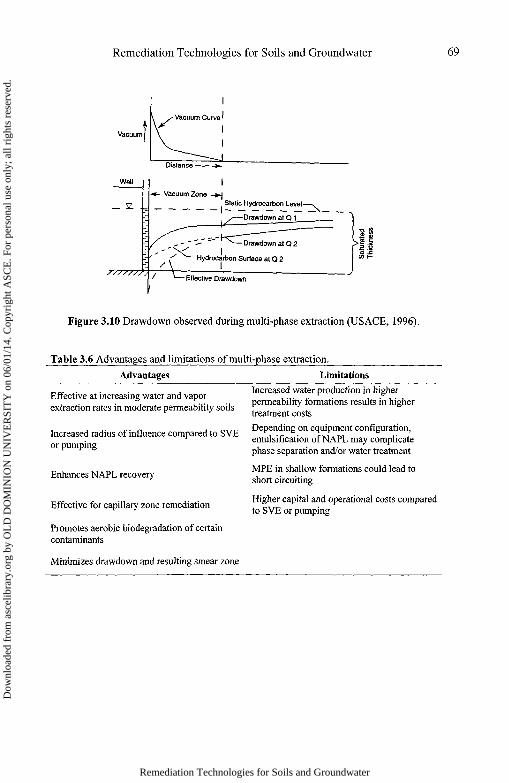
Vacuum application during MPE increases the hydraulic gradient toward theextraction well without creating a substantial drawdown. Effective drawdown is equal tothe sum of the induced vacuum and the physical drawdown. This concept is illustrated inFigure 3.10. Water and/or NAPL flow to the well can be effectively increased as a resultof the higher gradients. Since drawdown is controlled, MPE greatly reduces the risk ofLNAPL smearing. Due to the fact that the induced air flow supplies oxygen tosubsurface and could promote aerobic biodegradation, MPE is also referred to asbioslurping. Water, NAPL, and air extracted from the MPE wells are separated in aboveground phase separators, treated as required by the applicable regulations, and thendischarged into the environment.
Like SVE, MPE is also suitable for remediation of VOCs and some aerobicallybiodegradable SVOCs. In addition, MPE can be effectively used to recover NAPL,LNAPL in particular. MPE is most applicable to formations with moderate permeability(10~3 to 10"5 cm/s). In tighter formations, capillary pressures will be too high and result
Remediation Technologies for Soils and Groundwater
Dow
nloa
ded
from
asc
elib
rary
.org
by
OL
D D
OM
INIO
N U
NIV
ER
SIT
Y o
n 06
/01/
14. C
opyr
ight
ASC
E. F
or p
erso
nal u
se o
nly;
all
righ
ts r
eser
ved.

68 Remediation Technologies for Soils and Groundwater
in a smaller radius of influence. MPE costs escalate rapidly in more permeableformations due to increased water production. Extraction well yields of 5 gpm or less areconsidered suitable for entrainment extraction (EPA, 1997). Theoretical maximumsuction lift is 33.9 ft of water. However, the lighter-than-water mixture of entrainedliquids can be lifted to higher levels. Liquid extraction from a depth of 210 ft at onelocation was noted in the literature (NFESC, 1998). Several advantages and limitationsof using MPE are listed in Table 3.6.
The first step in MPE system design involves determining the radius ofinfluence, gas and liquid flow rates. This information is then used to design wells, wellspacing, and aboveground equipment such as vacuum pumps, phase separators, andother treatment units. Two primary approaches to MPE design are computer modelingusing multi-phase flow models and field pilot testing. Of these, field pilot testing is morecommonly practiced, although a combination of limited field testing and computermodeling lends a better design approach. The specific remedial objective of the MPEsystem (enhancement of SVE, NAPL recovery, or enhancement of groundwater yield)must be understood clearly prior to conducting the pilot test and full-scale design, asoptimal recovery of one phase could greatly affect recovery of the other phases. Theapplicability of MPE process for LNAPL recovery is well understood and documentedcompared to DNAPL recovery.
Dual phase extraction was conducted at the U.S. Defense Supply CenterRichmond's Acid Neutralization Pit site for remediation of soil and groundwatercontaminated with PCE and TCE. The impacted soil consisting of silty clay, fine andcoarse grained sand and interlayered gravel extended from the surface to 25 feet below.The depth of water table ranged from 10 to 15 feet. The transmissivity of the upperaquifer ranged between 35 to 47 m2/day with a hydraulic gradient of 0.001 to 0.002m/m. The treatment system consisted of 12 dual phase extraction wells and six airinjection wells located in a rectangular grid pattern. Each extraction well consisted of asealed casing to maintain vacuum for vapor extraction, and a submersible pump forgroundwater extraction. Extraction wells penetrated to a depth of 22 to 28 feet belowsurface. A low-pressure blower was utilized for air injection. Extracted groundwater wassubjected to air stripping. Off-gas from the stripper and vapors from the SVE systemwere vented into the atmosphere. The cost of pilot and aquifer testing was $134,092.Engineering design of the DPE system cost $73,198. Equipment cost was $205,743.Startup costs were $24,309 and the cost for one year of operation and maintenance was$101,148. The total per unit cost for the treatment was $0.03/gallon for the 17 milliongallons of groundwater recovered.
Remediation Technologies for Soils and Groundwater
Dow
nloa
ded
from
asc
elib
rary
.org
by
OL
D D
OM
INIO
N U
NIV
ER
SIT
Y o
n 06
/01/
14. C
opyr
ight
ASC
E. F
or p
erso
nal u
se o
nly;
all
righ
ts r
eser
ved.
Remediation Technologies for Soils and Groundwater 69
Figure 3.10 Drawdown observed during multi-phase extraction (USAGE, 1996).
Table 3.6 Advantages and limitations of multi-phase extraction.
Advantages Limitations
Effective at increasing water and vaporextraction rates in moderate permeability soils
Increased radius of influence compared to SVEor pumping
Enhances NAPL recovery
Effective for capillary zone remediation
Promotes aerobic biodegradation of certaincontaminants
Increased water production in higherpermeability formations results in highertreatment costs
Depending on equipment configuration,emulsification of NAPL may complicatephase separation and/or water treatment
MPE in shallow formations could lead toshort circuiting
Higher capital and operational costs comparedto SVE or pumping
Minimizes drawdown and resulting smear zone
Remediation Technologies for Soils and Groundwater
Dow
nloa
ded
from
asc
elib
rary
.org
by
OL
D D
OM
INIO
N U
NIV
ER
SIT
Y o
n 06
/01/
14. C
opyr
ight
ASC
E. F
or p
erso
nal u
se o
nly;
all
righ
ts r
eser
ved.
70 Remediation Technologies for Soils and Groundwater
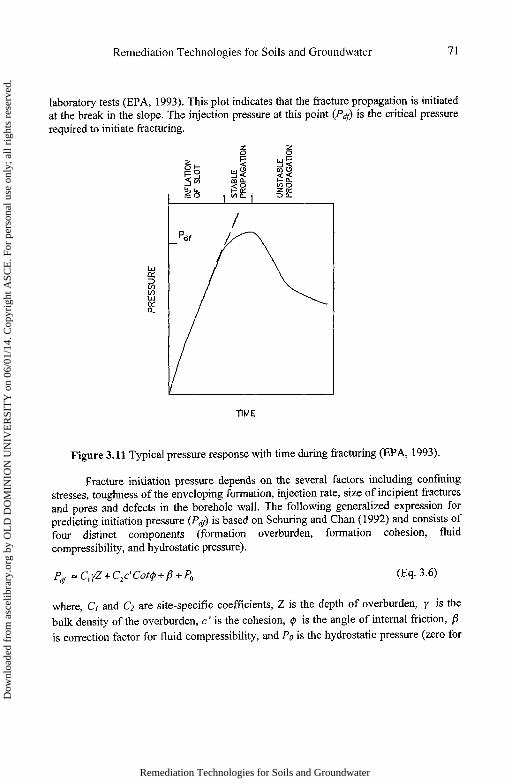
Three types of fracturing techniques (hydraulic, pneumatic, and blast) arecommercially available for environmental applications. As the names imply, hydraulicfracturing uses pressurized liquids, pneumatic fracturing uses pressurized air, and blastfracturing detonates high explosives to propagate fractures (GWRTAC, 2002).Typically, a fluid is injected into a borehole until the injection pressure exceeds a criticalvalue. Figure 3.11 shows a typical plot of injection pressure versus time obtained during
3.8 Induced Fracturing
Most in-situ remediation technologies involve circulation of carrier fluids (water,air or other gases) either to deliver amendments or recover contaminants. Lowpermeability formations severely limit the circulation of these carrier fluids, and henceeffectiveness of the intended remedy. Fractures can be induced in low-permeability silts,clays, silty sands and bedrock materials such as shale, limestone and sandstone toenhance their permeability. The fracturing technology is not contaminant specific, asfracturing alone does not treat or remove any contaminants. A network of inducedfractures helps improve the advective transport and shorten the diffusive transportpathways. As a result, delivery of carrier fluids and recovery from these low-permeability formations becomes more efficient. Fracturing can enhance theeffectiveness of a variety of remediation approaches including SVE, MPE, and airsparging. Fracturing technologies can be readily extended to deliver amendments forbioremediation, emplace oxidants for in-situ chemical oxidation, zero-valent iron forabiotic degradation of chlorinated VOCs and graphite to improve electrokinetics. Table3.7 presents a summary of key advantages and limitations of the induced fracturingprocess.
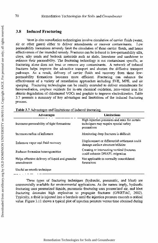
Table 3.7 Advantages and limitations of induced fracturing.Advantages Limitations
Increases permeability of tight formations
Increases radius of influence
Enhances vapor and fluid recovery
Reduces formation heterogeneities
Helps effective delivery of liquid and granularamendments
Useful as retrofit technique
High injection pressures and rates for certaintechniques may require special safetyprecautions
Monitoring deep fractures is difficult
Displacement or differential settlement coulddamage surface structure/utilities
Creating or intersecting vertical fracturescould enhance DNAPL migration
Not applicable to normally consolidatedformations
Remediation Technologies for Soils and Groundwater
Dow
nloa
ded
from
asc
elib
rary
.org
by
OL
D D
OM
INIO
N U
NIV
ER
SIT
Y o
n 06
/01/
14. C
opyr
ight
ASC
E. F
or p
erso
nal u
se o
nly;
all
righ
ts r
eser
ved.
Remediation Technologies for Soils and Groundwater 71
laboratory tests (EPA, 1993). This plot indicates that the fracture propagation is initiatedat the break in the slope. The injection pressure at this point (df) is the critical pressurePrequired to initiate fracturing.
Figure 3.11 Typical pressure response with time during fracturing (EPA, 1993).
Fracture initiation pressure depends on the several factors including confiningstresses, toughness of the enveloping formation, injection rate, size of incipient fracturesand pores and defects in the borehole wall. The following generalized expression forpredicting initiation pressure (Pdf) is based on Schuring and Chan (1992) and consists offour distinct components (formation overburden, formation cohesion, fluidcompressibility, and hydrostatic pressure).
where, Cy and C2 are site-specific coefficients, Z is the depth of overburden, 7 is thebulk density of the overburden, c' is the cohesion, 0 is the angle of internal friction, fiis correction factor for fluid compressibility, and P0 is the hydrostatic pressure (zero for
Remediation Technologies for Soils and Groundwater
Dow
nloa
ded
from
asc
elib
rary
.org
by
OL
D D
OM
INIO
N U
NIV
ER
SIT
Y o
n 06
/01/
14. C
opyr
ight
ASC
E. F
or p
erso
nal u
se o
nly;
all
righ
ts r
eser
ved.
72 Remediation Technologies for Soils and Groundwater
vadose zone). For hydraulic fracturing, assuming water to be incompressible sets /3 tozero.
In hydraulic fracturing, a high-pressure water jet (18 L/min and 20 MPa) is usedto cut approximately a 6-inch, disk-shaped notch at the required depth in a borehole. Thepurpose of the notch is to reduce the fracture initiation pressure and ensure that thefracture starts in a horizontal plane. Water is then injected into the borehole at a rate of20-40 L/min, to initiate a hydraulic fracture at the notch (Murdoch and Slack, 2002). Aslurry of cross-linked guar gum gel and sand is pumped into the borehole to propagatethe fracture. The fracture propagates a moderate rate of 0.1± m/sec and a single injectionnormally takes 15 to 30 minutes (GWRTAC, 2002). The viscous guar gum is capable ofsuspending 10 to 15 Ib of sand per gallon of gel (EPA, 1994). An enzyme is added tobreak the guar gum several hours after the injection, leaving sand within the fracture toprop the fracture open.
Pneumatic fracturing involves injecting high volumes (25 to 50 m /min) of air ora gas at high pressure (0.5 to 2.0 MPa) into an isolated section of a borehole over a 15 to20 second interval (EPA, 1994). Fractures propagate at a rapid rate of- 2.0 m/sec. Aseries of gas cylinders are used to provide the high volume and high pressure needed forpneumatic fracturing. Proppants are typically not used with pneumatic fracturing and theprocess relies on "self-propping" fractures. Self-propping is thought to be a combinationof asperities along the fracture surface and shifting of geological media. The lowviscosity of air results in rapid leak-off (fluid loss into the formation), thus requiring ahigh volume of flow to propagate the fractures. The fracture initiation pressures inpneumatic fracturing are approximately twice those required for hydraulic fracturing dueto the higher compressibility of air (Schuring and Chan, 1992).
All reported cases of blast-enhanced fracturing for remediation purposes havebeen applied to bedrock formations primarily to enhance pump-and-treat systems.Subsurface fractures are created by placing explosives in open bedrock boreholes anddetonating them. Such detonations create an intensely fractured area of bedrock that isessentially rubble (referred as fracture trench). The fracture trench acts as an effectivegroundwater sink from which increased volumes of groundwater can be pumped(GWRTAC, 1996). Fractures propagate at the fastest rate (300± m/sec) in blastfracturing. Blast fractures are self-propping similar to pneumatic fractures.Emplacement of amendments by hydraulic and pneumatic fracturing processes is welldeveloped; however, it is under development in case of blast fracturing.
The cost of hydraulic and pneumatic fracturing depends on the number offractures produced per borehole (ITSR, 1998). EPA estimates the cost of a singlehydraulic fracture to be between $950 and $1,425 (EPA, 1993). Approximately 35% ofthe costs are associated with labor. The daily cost of 4 to 6 fractures was estimated to be
Remediation Technologies for Soils and Groundwater
Dow
nloa
ded
from
asc
elib
rary
.org
by
OL
D D
OM
INIO
N U
NIV
ER
SIT
Y o
n 06
/01/
14. C
opyr
ight
ASC
E. F
or p
erso
nal u
se o
nly;
all
righ
ts r
eser
ved.

Remediation Technologies for Soils and Groundwater 73
$5,700 (EPA, 1993). Cost of pneumatic fracturing at a technology demonstration projectin New Jersey was estimated at $308/kg of TCE removed. Pneumatic fracturing costscan also be estimated as $10 to $22/m3 of soil treated (ISTR, 1998). Fracturing reducesoverall costs of remediation by increased mass removal of contaminants and more rapidcleanup.
3.9 Soil Heating
Soil heating is a remediation approach that can be combined with SVE toimprove contaminant removal from saturated and unsaturated zones at polluted sites.This technology employs six-phase electrical heating of soils to remove contaminantsthat are strongly sorbed to soil matrices and may be difficult to treat using SVE alone. Inthis approach, three-phase electricity from a conventional utility power transformer isconverted into six phases, and each phase is delivered to a single electrode placed alonga hexagonal pattern (Figure 3.12). Six-phase soil heating (SPSH) uses electrical resistiveheating to raise soil temperature and facilitate desorption of the contaminant into the gasphase. Strategically placed extraction wells remove the gas phase for on-site treatment.The amount of heating achieved is a function of the soil moisture content. Low soilpermeability and high moisture contents result in better heating. Steam resulting fromvaporization of soil moisture helps in removing strongly bound contaminants.
Figure 3.12 Schematic illustrating the application of six-phase soil heating (SPSH) to acontaminated soil (FRTR, 2006).
Remediation Technologies for Soils and Groundwater
Dow
nloa
ded
from
asc
elib
rary
.org
by
OL
D D
OM
INIO
N U
NIV
ER
SIT
Y o
n 06
/01/
14. C
opyr
ight
ASC
E. F
or p
erso
nal u
se o
nly;
all
righ
ts r
eser
ved.

74 Remediation Technologies for Soils and Groundwater
SPSH was evaluated for DNAPL removal during a field test conducted at theGroundwater Remediation Field Laboratory at Dover Air Force Base, Delaware(Peurrung and Bergsman, 1997). The ground water table at the site was located 25 feetbelow surface and formed an aquifer of thickness between 5 to 7 feet underlain by adense clay layer. The subsurface soil consisted of sand and gravel with thin layers ofclay and silt. Electrodes were inserted to a depth of 35 feet along a circle of 30 feetdiameter. This formed a treatment zone of approximately 42 feet diameter by 15 feetthickness. The system design allowed heating of the entire saturated depth and 5 feet ofthe unsarurated depth. On-site equipment included a conventional utility powertransformer, a collection header, a vacuum blower, a condenser and knockout box, andgranular activated carbon drums to manage off gas and condensate. Most of the DNAPLintroduced to the site was removed from the soil in 21 days. During this time, 136,000kW-hrs of energy was used and 29,000 gallons of condensate was removed from thesite. At $0.07/kW-hr, this represented an energy cost of approximately $16/m3 soiltreated.
Soil heating can also be achieved by using electromagnetic energy in the radiofrequency band (EPA 1995). Radio frequency heating (RFH) is often employed inconjunction with SVE to improve contaminant removal. The soil is heated using anarray of exciter electrodes inserted in the contaminated soil. Energy is applied to thisarray of electrodes. Two rows of ground electrodes are positioned on either side of theexciter electrodes forming a triplate capacitor. The application of energy to the centralarray of electrodes, results in dielectric heating of the surrounding soil. Soil temperaturescan rise to over 300°C. The heating results in vaporization of contaminants and moisture,which are subsequently removed by vapor extraction wells.
The Illinois Institute of Technology Research Institute evaluated RFH at KellyAir Force Base in San Antonio, TX (EPA 1995). A 40-kW radio frequency generatorwas used as the energy source. Exciter electrodes consisting of 2.5 and 4-inch diametercopper pieps were installed in 10-inch bore holes to a depth of 19.5 feet. Four exciterelectrodes were installed 2.5 feet apart and two rows of eight ground electrodes (2-inchdiameter aluminum pipes) were positioned on either side of the exciter array. The RFHsystem raised the temperature of the target zone to 150°C. The system was operated for a9-week duration followed by a 2-month cool down period. This study found thatconcentrations of total recoverable petroleum hydrocarbons were reduced by an averageof 95%.
Soil heating can also be achieved by the injection of steam into the subsurface(EPA 1998b). This technology was first developed by the petroleum industry for theenhanced recovery of product from geological formations. In the case of remediation,steam injected above or below the groundwater table heats the soil and water around theinjection well. Some heated water moves away from the injection well. Eventually the
Remediation Technologies for Soils and Groundwater
Dow
nloa
ded
from
asc
elib
rary
.org
by
OL
D D
OM
INIO
N U
NIV
ER
SIT
Y o
n 06
/01/
14. C
opyr
ight
ASC
E. F
or p
erso
nal u
se o
nly;
all
righ
ts r
eser
ved.
Remediation Technologies for Soils and Groundwater 75
surrounding water is heated to the temperature of the steam and is vaporized in situ.Steam injection results in the development of three distinct zones in the subsurface: thesteam zone, the variable temperature zone, and the ambient temperature zone. The steamand hot water travel through the contaminated media and displace contaminants that areeither sorbed to soil particles or present as NAPLs. The hot water reduces the viscosityof the NAPL making it easier to be displaced.
Both contaminant and soil types are important factors that can impact the successof steam injection. The Henry's Law constant of the contaminant will indicate itslikelihood to volatilize. Steam injection is most appropriate for the removal of trappedlenses of volatile or semivolatile contaminants that may otherwise not be removed byhot water displacement of vacuum extraction. Steam injection is much more likely to besuccessful for sandy or gravelly soils with low organic matter contents than for finersoils with higher organic matter. Subsurface heterogeneity can significantly impactremediation efficiency using steam injection.
The primary design parameter for a steam injection process is the steam injectionrate. Other design considerations include injection pressure, temperature and steamquality. Injection pressures should be controlled to prevent fracturing of soil, which canlead to loss of steam to the surface. Higher injection rates can result in faster heating ofthe subsurface. However, once steam breakthrough occurs, improved thermal efficiencycan be achieved by reducing the injection rate. Greater heating rates result in greaterrecoveries and better energy efficiency. Higher steam quality, defined as the proportionof the total water in the vapor phase, produce better contaminant extraction efficiencies.
Steam stripping has been used as a remediation technology in the Netherlandssince the early 1980's. In the U.S., a small-scale pilot demonstration project wasconducted in San Jose, CA, in 1988 where surface spills and leaking undergroundstorage tanks had caused the release of several VOCs (EPA 1998b). SVE and steaminjection were performed cyclically. This approach was effective in rapidly removing aconsiderable portion of the contaminants. However, low permeability zones appeared toretain contaminants at high levels.
Steam injection was evaluated to recover JP-5 fuel at the Naval Air StationLemoore in Lemoore, CA in 1994 (EPA 1998b). The remediation system consisted ofeight extraction wells that enclosed two injection wells. The concentration of totalpetroleum hydrocarbons in the unsaturated zone within the treatment area was reducedfrom approximately 100,000 ppm to 20 to 50 ppm. However, contaminant levelsremained at 20,000 ppm at and below the groundwater table. Contaminantconcentrations increased at the interface of the surface clay layer and underlying silt dueto the upward migration of contaminated vapors.
Remediation Technologies for Soils and Groundwater
Dow
nloa
ded
from
asc
elib
rary
.org
by
OL
D D
OM
INIO
N U
NIV
ER
SIT
Y o
n 06
/01/
14. C
opyr
ight
ASC
E. F
or p
erso
nal u
se o
nly;
all
righ
ts r
eser
ved.

76 Remediation Technologies for Soils and Groundwater
3.10 Conclusion
This chapter described eight commonly used physical treatment processes forsoil and groundwater remediation. Physical treatment of contaminated subsurface mediaremains popular because of predictable end results and continued public acceptance.These processes are also being used in combination with chemical or biologicaltreatment techniques. Pump-and-treat remains a common plume control method. It isexpected that in coming years research and improved understanding of physicochemicalprocesses will bring newer technologies to the market while improving the performanceof existing remediation methods. Greater insights will also lead to the effectivedeployment of remediation approaches that combine the best characteristics of "active"physical processes and "passive" chemical or biological techniques.
References
AFCEE (1997). Test Plan and Technical Protocol for Bioslurping. Air Force Center forEnvironmental Excellence, Battelle Press, Columbus, OH.
Bedient, P.B.; Rifai, H.S.; Newell, C.J. (1994) In Ground Water Contamination:Transport and Remediation. Prentice Hall, Inc. Englewood Cliffs, NJ.
Cohen, R.M.; Vincent, A.H.; Mercer, J.W.; Faust, C.R.; Spalding, C.P. (1994) Methodsfor Monitoring Pump-and-Treat Performance. U.S. Environmental ProtectionAgency Pub. No. 600/R-94/123. R.S. Kerr Environmental Research Laboratory,Ada, OK.
DENIX (2006). Defense Environmental Network & Information Exchange, URL:www.denix.osd.mil/
EPA (1993) "Hydraulic Fracturing Technology - Technology Evaluation Report." U.S.Environmental Protection Agency Pub. No.540/R-93/505, Risk ReductionEngineering Laboratory, Cincinnati, OH.
EPA (1994) "Alternative Methods for Fluid Delivery and Recovery." U.S.Environmental Protection Agency Pub. No.625/R-94/003, Office of Research andDevelopment, Washington, DC.
EPA (1995) "IITRI Radio Frequency Heating Technology" U.S. EnvironmentalProtection Agency Pub No. 540/R-94/527a, Office of Research and Developent,Washington, DC.
EPA (1996a) "How to Effectively Recover Free Product At Leaking UndergroundStorage Tank Sites: A Guide for State Regulators." U.S. Environmental ProtectionAgency Pub. No. 510-R-96-001, Office of Research and Development, WashingtonDC.
EPA (1996b) "Pump-and-Treat Ground-Water Remediation. A Guide for DecisionMakers and Practitioners." U.S. Environmental Protection Agency Pub. No. 625/R-95/005, Office of Research and Development, Washington DC.
Remediation Technologies for Soils and Groundwater
Dow
nloa
ded
from
asc
elib
rary
.org
by
OL
D D
OM
INIO
N U
NIV
ER
SIT
Y o
n 06
/01/
14. C
opyr
ight
ASC
E. F
or p
erso
nal u
se o
nly;
all
righ
ts r
eser
ved.
Remediation Technologies for Soils and Groundwater 77
EPA (1997) "Analysis of Selected Enhancements for Soil Vapor Extraction." U.S.Environmental Protection Agency Pub. No. 542/R-97/007, Office of Research andDevelopment, Washington DC.
EPA (1998a) "Field Applications of In Situ Remediation Technologies: GroundwaterCirculation Wells." U.S. Environmental Protection Agency Pub. No. 542/R-98/009,Office of Solid Waste and Emergency Response, Washington DC.
EPA (1998b) "Ground Water Issue. Steam Injection for Soil and Aquifer Remediation."U.S. Environmental Protection Agency Pub No. 540/S-97/505. Office of Researchand Development, Washington, DC.
EPA (1999) "Cost and Performance Summary Report. Soil Vapor Extraction at CampLeJeune Military Reservation, Site 82, Area A, Onslow County, North Carolina."U.S. Environmental Protection Agency CERCLIS ID Number NC6170022580,Office of Solid Waste and Emergency Response, Technology Innovation Office,Washington, DC.
EPA (200la) "Groundwater Pump and Treat Systems: Summary of Selected Cost andPerformance Information at Superfund-financed Sites." U.S. EnvironmentalProtection Agency Pub No. 542-R-01-021b. Office of Solid Waste and EmergencyResponse, Washington, DC.
EPA (2001b) "Cost Analyses for Selected Groundwater Cleanup Project" U.S.Environmental Protection Agency Pub No. 542-R-00-013. Office of Solid Waste andEmergency Response, Washington, DC.
EPA (200 Ic) "GCWs used with air stripping and UV technologies to remove TCE andRDX." In Ground Water Currents. U.S. Environmental Protection Agency Pub No.542-N-01-007. Office of Solid Waste and Emergency Response, Washington, DC.
EPA (2002) "How to Evaluate Alternative Cleanup Technologies for UndergroundStorage Tank Sites: A Guide for Corrective Action Plan Reviewers." U.S.Environmental Protection Agency Pub. No.510-R-04-002, Office of Solid Waste andEmergency Response, Washington DC.
ESTCP (2001) "Use of Cometabolic Air Sparging to Remediate Chloroethene-Contaminated Groundwater Aquifers." Environmental Security TechnologyCertification Program Report No. CU-9810, U.S. Department of Defense.
FRTR (2006) Remediation Technologies Screening Matrix and Reference Guide,Version 4.0. Federal Remediation Technologies Roundtable. URL: www.frtr.gov
GWRTAC (1996) "Technology Overview Report: Blast-Enhanced Fracturing."Groundwater Remediation Technologies Analysis Center Pub. No.TO-96-01,Pittsburgh, PA.
GWRTAC (1997) "Technology Overview Report: In-Well Vapor Stripping."Groundwater Remediation Technologies Analysis Center Pub. No.TO-97-01,Pittsburgh, PA.
GWRTAC (2001) "Technology Evaluation Report: Fracturing Technologies to EnhanceRemediation." Groundwater Remediation Technologies Analysis Center Pub.No.TE-02-02, Pittsburgh, PA.
Remediation Technologies for Soils and Groundwater
Dow
nloa
ded
from
asc
elib
rary
.org
by
OL
D D
OM
INIO
N U
NIV
ER
SIT
Y o
n 06
/01/
14. C
opyr
ight
ASC
E. F
or p
erso
nal u
se o
nly;
all
righ
ts r
eser
ved.
78 Remediation Technologies for Soils and Groundwater
ITSR (1998) "Hydraulic and Pneumatic Fracturing." Innovative Technology SummaryReport No. 1916 and 1917. U.S. Department of Energy, Office of EnvironmentalManagement.
Jawitz, J.W.; Sillan, R.K.; Annable, M.D.; Rao, P.S.C.; Warner, K. (2000) "In-situalcohol flushing of a DNAPL source zone at a dry cleaner site." Environ. Set.TechnoL 34, 3722-3729.
Kuhlman, M.I. (2002) "Analysis of the steam injection at the Visalia Superfund Projectwith fully compositional nonisothermal finite difference simulations." J. Haz. Mat.92, 1-19.
Leeson, A.; Johnson, P.C.; Vogel, C.M.; Hinchee, R.E.; Marlee, M.; Peargin, T.; Bruce,C.L.; Amerson. I.L.; Coonfare, C.T.; Gillespie, R.D.; McWhorter, D.B. (2002) "Airsparging design paradigm." Battelle Corp., Columbus OH. Website of theEnvironmental Security Technology Certification Program (ESTCP):http://www.estcp.org/documents/techdocs/Air_Sparging.pdf
Masters, G.M. (1996) Introduction to Environmental Engineering and Science. PrenticeHall, Upper Saddle River, NJ.
Murdoch L.C., and Slack W.W. (2002) "Forms of Hydraulic Fractures in Shallow Fine-Grained Formations." Journal ofGeotech. And Geoenv. Engg. 128(6), 479-487.
NFESC (1998). "Application Guide for Bioslurping - Volume II: principles and Practiceof Bioslurping." Naval Facilities Engineering Service Center, Pub. TechnicalMemorandum TM-2301-ENV, Port Hueneme, California.
NRC (1994). Alternatives for Ground Water Cleanup. National Research Council.National Academy Press.
NRL (1999). "Groundwater Circulating Well Technology Assessment." Naval ResearchLaboratory, Pub. No.NRL/PU/6115-99-384, Washington DC.
Peurrung, L.M>, and Bergsman, T.M. (1997) Applications Analysis Report: Six-PhaseSoil Heating of the Saturated Zone, Dover Air Force Base, Delaware." ProjectReport for Pacific Northwest National Laboratory:http://www.cesiweb.com/dover.htm
Schuring, J.R.; Chan, P.C. (1992) "Removal of Contaminants from Vadose Zone byPneumatic Fracturing ." New Jersey Institute of Technology, Prepared for the UnitedStates Geological Survey, Department of Interior.
USDOE (2002). "Innovative Technology Summary Report: In-Well Vapor Stripping."U.S. Department of Energy, Pub. No.DOE/EM-0626, Office of EnvironmentalManagement, Washington DC.
USAGE (1999). "Multi-Phase Extraction - Engineer Manual" U.S. Army Corps ofEngineers, EM 1110-1-4010, Department of the Army, Washington DC.
Remediation Technologies for Soils and Groundwater
Dow
nloa
ded
from
asc
elib
rary
.org
by
OL
D D
OM
INIO
N U
NIV
ER
SIT
Y o
n 06
/01/
14. C
opyr
ight
ASC
E. F
or p
erso
nal u
se o
nly;
all
righ
ts r
eser
ved.