release notes for cisco ons 15454 release...
TRANSCRIPT

5454
,
URL:
Release Notes for Cisco ONS 15454Release 3.0.2
Release Notes address closed (maintenance) issues, caveats, and new features for the Cisco ONS 1SONET multiplexer. For detailed information regarding features, capabilities, hardware, and softwareintroduced with this release, refer to Release 3.0. of theCisco ONS 15454 Installation and Operations GuideCisco ONS 15454 Troubleshooting and Reference Guide,and Cisco ONS 15454 TL1 Command Guide.Forthe most current version of the Release Notes for Cisco ONS 15454 Release 3.0.2, visit the following
http://www.cisco.com/univercd/cc/td/doc/product/ong/15400/454relnt/index.htm
ContentsThis document contains the following sections:
• Changes to the Release Notes, page 2
• Maintenance Issues Closed in Release 3.0.2, page 3
• Caveats, page 9
• New Features and Functionality, page 21
• Related Documentation, page 41
• Obtaining Documentation, page 41
• Obtaining Technical Assistance, page 42
Corporate Headquarters: Cisco Systems, Inc., 170 West Tasman Drive, San Jose, CA 95134-1706 USA
Copyright © 2001. Cisco Systems, Inc. All rights reserved. October 2001

Changes to the Release Notes
e
Changes to the Release NotesThis section documents supplemental changes that have been added to theRelease Notes for Cisco ONS15454 Release 3.0.2 since the production of the Cisco ONS 15454 System Software CD for Releas3.0.2.
The following supplemental changes to the release notes for Release 3.0.2 have been added.
Changes to Maintenance Issues Closed in Release 3.0.2
Maintenance and Administration
• DDTS # CSCdu27989, page 5
Caveat Changes
Maintenance and Administration
• DDTS # CSCdt86355, CSCdv14052, page 11
• DDTS # CSCdv22380: CORBA Communication Exception, page 11
• DDTS # CSCct03396 Ring Map Change Dialog Box, page 11
• DDTS # CSCdw06182, page 11
• Span Upgrade, page 11
• DDTS # CSCdv55792, page 12
• DDTS # CSCdv62990, page 12
• DDTS # CSCdv33367, page 12
• DDTS # CSCdu40207, page 12
• DDTS # CSCdv46209, page 12
Performance Monitoring
• DS1 Electrical Transmit Path PMs, page 15
• DDTS # CSCdv73802 and CSCdv74996 Far End PM Monitoring, page 15
• DDTS # CSCdv26401, page 16
• DDTS # CSCdv10889 and # CSCdv47419, page 16
Changes to New Features and Functionality
TL1
• CTAGs, page 34
2Release Notes for Cisco ONS 15454 Release 3.0.2
October 2001

Maintenance Issues Closed in Release 3.0.2
nfield
e aings
.0.0.
areationaso intoxceptfalls
w. Toisioningetting, or
and nossful.CC+
n be12,
d.
• Password Enforcement, page 34
Maintenance Issues Closed in Release 3.0.2
Upgrades
DDTS # CSCdu38992
Cisco recommends Release 3.0.0 for new system installations (or what is commonly termed “Greeapplications”) only.
When you upgrade from ONS 15454 Release 2.2.x to 3.0.0, a condition may arise that can causpost-upgrade reset of the node at a point after the upgrade process after you perform a provisionchange on the node. During testing, this condition was experienced in less than 2% of the systemupgraded. This condition will not be seen on new, or “Greenfield,” systems initialized with Release 3
As the node activates the new software load, each card in the node is loaded with the new softwrelease. If any one of the cards fails to load the software successfully, you may see a communicfailure (CONTBUS) condition that persists after the activation is completed indicating the node hentered this state. Once the node is in this state, any provisioning changes will cause the node to ga system-wide reset wherein all cards perform a soft reboot and reload the new software image (efor the card that failed to reset originally; this card must be either reseated or replaced). If the nodeinto this condition, traffic may be affected on provisioned circuits.
If you choose to upgrade nodes to Release 3.0.0, perform the upgrade within a maintenance windoensure that your upgrade activation has succeeded, Cisco recommends that you execute a provchange to the node by toggling the timing reference (waiting one minute between toggles), thus sa 30-minute timer in motion and allowing the node reset to occur during the maintenance windowwhile personnel are on site. If the node does not reset 30 minutes after the provisioning change SYSBOOT alarm is present in the CTC alarms panel for the node, the software activation was succeFor details on this procedure, see “Upgrading Cisco ONS 15454 Release 2.2.x to 3.0.0 Using the TCard.”
This issue is resolved in Release 3.0.1.
DDTS # CSCdu35824
After an upgrade from Release 2.2.x to 3.0, pointer justification thresholds are incorrect. They cazero or a number that is too large. Incorrect pointer justification thresholds occur with OC-3, OC-OC-48, and EC-1 cards. This issue will not occur for new OC-N cards inserted after an upgrade.
This issue is resolved in Release 3.0.1.
DDTS # CSCdu20446
In previous releases, a CTC I/O exception could occur during an activation to a new software loa
This issue is resolved in Release 3.0.1.
3Release Notes for Cisco ONS 15454 Release 3.0.2
October 2001

Maintenance Issues Closed in Release 3.0.2
ction
on”ctive.
d bus
tive
Ports
Traffic Protection
False UNEQ-P Alarms
In previous releases, false unequipped path (UNEQ-P) alarms might have occurred during proteswitching between cards.
This issue is resolved in Release 3.0.
Traffic Loss When Resetting an Electrical Card While in Lock on
In previous releases, if you placed a working card from an electrical protection group in the “Lockstate and performed a soft reset of the card, you would lose traffic until the working card became a
This issue is resolved in Release 3.0.
Line Cards
DDTS # CSCdu36139
In previous releases, traffic hits or loss could occur after deleting an adjacent drop card. A payloaalarm accompanies the service-affecting incident. This issue has occurred with the EC-1 card.
This issue is resolved in Release 3.0.1.
DDTS # CSCdu34969
Removing the active TCC+ can cause a communication bus failure (CONTBUS) alarm.
This issue is resolved in Release 3.0.1.
False Card Failure Alarms
In previous releases, false card-failure alarms could appear during hard resets (card pulls) of acXCVT cards.
This issue is resolved in Release 3.0.
DDTS # CSCct03114
In previous releases, SONET section data communication channel (SDCC) was only supported on1 and 3 of the four-port OC-3 card.
This issue is resolved in Release 3.0.
4Release Notes for Cisco ONS 15454 Release 3.0.2
October 2001

Maintenance Issues Closed in Release 3.0.2
ny filessions
iew,e the
15454s, or
tely
e VTtherlarmslearThis
thensions
eriodost,
Maintenance and Administration
DDTS # CSCdu27989
When a network has too many concurrent CTC sessions open, CTC can subsequently open too mahandles, resulting in an unexpected TCC reset. To avoid this issue, restrict the number of CTC seto a maximum of four.
This issue is resolved in Release 3.0.x, which allows a user to log in with "Exclude DynamicallyDiscovered Nodes" enabled. This opens a node level view rather than the typical network level vlimiting the number of open file handles on the local node. Releases 3.0 and forward also optimiznumber of file handles opened during initialization.
DDTS # CSCdt86355, CSCdv14052
Previous releases of CTC were capable of losing synchronized status between CTC and an ONSnode. Symptoms indicating that this issue has arisen might be inaccurate card status, false alarmother misinformation reported by CTC. To resolve this issue, reset the TCC+ card, then immediaclose the CTC session. A new CTC session should show the correct status for the node.
This issue is resolved in Release 3.0.2.
DDTS # CSCdu28401
In previous releases, false AIS-V and UNEQ-V alarms could be raised on the trunk cards for somcircuits. Traffic remained error-free. This issue could occur in a BLSR after node isolation, or in oprotection mechanisms (UPSR, 1+1) if multiple switches occurred in rapid succession. The false acould also be raised if a VT circuit was deleted while it was alarmed. The alarm condition will not con its own. To clear the alarms you must force a switch from the active TCC+ to the standby TCC+.will force an alarm resynchronization and clear the erroneous alarms.
This issue is resolved in Release 3.0.2.
DDTS # CSCdu26570
In previous releases, if you selected multiple circuits in two concurrently running CTC sessions anddeleted the circuits simultaneously, the TCC+ might have reset. This occured when two CTC seswere connected to the same node and STS or VT circuits were set up on the node.
This issue is resolved in Release 3.0.2.
DDTS # CSCdv22380: CORBA Communication Exception
In previous releases, if CTM was connected to an ONS 15454 network (or node) for a prolonged p(48 hours +), the connection could fail with a “Corba:comm.” failure error. Once the connection is lit will not return. The workaround was to restart the client software.
This issue is resolved in Release 3.0.2.
5Release Notes for Cisco ONS 15454 Release 3.0.2
October 2001

Maintenance Issues Closed in Release 3.0.2
routenodeork
OS)
s .
VT
n either If a
DDTS # CSCdu53428
Normally you can connect a workstation directly to an ONS 15454 node and then provision a staticon the workstation, run CTC, and view the entire DCC network; however, in Release 3.0, if anotherin the network is connected to a LAN while OSPF is turned on for that LAN, some nodes in the netwmight not be visible from the CTC session on the workstation.
This issue is resolved in Release 3.0.1.
DDTS # CSCdu55720
In Release 3.0 default static routes do not propagate from a single node to the entire network. Topropagate to all nodes you must use a network or host route.
This issue is resolved in Release 3.0.1.
LOS on DS-1 Protect Card Reported as Minor, Non-Service Affecting After Switch
In previous releases, after a switch from the working to the protect DS-1 card, the loss of signal (Lalarm for the protect card (the new working card) might have been reported as having a minor,non-service affecting (MN NSA) severity instead of a major, service affecting (MJ SA) severity.
This issue is resolved in Release 3.0.
DDTS # CSCdt14510
In previous releases, DS3XM/DS-1 traffic might have been interrupted during software activation
This issue is resolved in Release 3.0.
DDTS # CSCdt53432: IMPROPRMVL Alarm
In previous releases, CTC did not consistently report improper removal (IMPROPRMVL) of XC/XCcards.
This issue is resolved in Release 3.0.
DDTS # CSCds15889: Add Node Feature
In previous releases, the Add Node feature was only supported when you added a new, isolated node ia bidirectional line switched ring (BLSR) or a unidirectional path switched ring (UPSR) configuration.node was already part of a network, the Add Node feature was not supported.This issue is resolved inRelease 3.0.
DDTS # CSCdt14323: Provisioning of C-Bit TCA
In previous releases, C-Bit Threshold Crossing Alerts (TCAs) in C-Bit framing mode could not beprovisioned from CTC.
This issue is resolved in Release 3.0.
6Release Notes for Cisco ONS 15454 Release 3.0.2
October 2001

Maintenance Issues Closed in Release 3.0.2
ps
LSR
on
sare
and
PSR
notted.
t was
DDTS # CSCdt82081: TIM-P Alarm on Protection Switch
In previous releases, existing path trace string mismatch (TIM-P) alarms in DS3E protection groumight have been lost during protection switches.
This issue is resolved in Release 3.0.
Interoperability
DDTS # CSCdt25702
In previous releases, when you provisioned circuits between rings on a node configured with both Band UPSR topologies, XC cards might have reset.
This issue is resolved in Release 3.0.
UPSR on Top of BLSR or 1+1
In previous releases, the TL1 interface erroneously allowed the user to overlay UPSR protectionBLSR or 1+1 protection.
In general, the working and protect UPSR paths should be over unprotected spans. However, it ipossible to route intermediate portions of a UPSR circuit over 1+1 or BLSR if the UPSR drop pointsnot on the same node where the 1+1 or BLSR is defined.
The UPSR drop can, however, be on a BLSR or 1+1. In other words, you can interconnect a UPSRa BLSR on the same node by “dropping” the UPSR circuit onto the BLSR or 1+1 spans.
This issue is resolved in Release 3.0; the TL1 interface now prevents the user from overlaying Uprotection on BLSR or 1+1 protection.
SONET/SDH
DDTS # CSCct04091
In previous releases, you had to provision all circuits as bidirectional. Unidirectional circuits weresupported. If a unidirectional circuit was provisioned, loss of signal (LOS) alarms would be genera
This issue is resolved in Release 3.0.
UPSR Functionality
DDTS #: CSCct03852
In previous releases, no alarm was reported when a UPSR protection switch occurred. The evenreported in the event log but not as a standing alarm.
This issue is resolved in Release 3.0.
7Release Notes for Cisco ONS 15454 Release 3.0.2
October 2001

Maintenance Issues Closed in Release 3.0.2
esetng,
ions
s in
.s on
uringo the
boot.
BLSR Functionality
DDTS # CSCdu38133 and CSCdu37768: Precautions Needed After BLSR Deletion
In previous releases, the following precautions were needed after deleting a BLSR:
To ensure optimum provisioning performance, after deleting a BLSR, perform a software-initiated ron the standby XC/XCVT and wait for it to reboot. When the standby XC/XCVT has finished rebootiperform a software-initiated reset on the active XC/XCVT.
This issue is resolved in Release 3.0.1.
DDTS # CSCdt38383: Force Switch on OC-48 Spans
In previous releases when forcing a switch on OC-48 spans in BLSR configurations, traffic disruptin excess of 50 ms could occur.
This issue is resolved in Release 3.0.
DDTS # CSCds58575: Fiber Pulls on OC-48 Spans
In previous releases, when pulling fibers on OC-48 spans in BLSR configurations, traffic disruptionexcess of 50 ms could occur.
This issue is resolved in Release 3.0.
Multiple Span Failure in a BLSR Configuration
In previous releases, Cisco did not recommend disabling multiple spans in a BLSR configurationMultiple span failures might have caused intermittent switching between working and protect paththe circuits in the remaining spans.
This issue is resolved in Release 3.0.
Synchronization
DDTS # CSCdr03214
In previous releases, line-timed nodes could lose connectivity to their primary reference source dsoftware upgrades. The loss of connectivity forced the nodes into a hold-over state or to switch tsecondary source. This did not affect traffic.
This issue is resolved in Release 3.0.
TL1
DDTS # CSCdv12827
In previous releases, execution of the RTRV-BLSR command might have caused the TCC+ to re
8Release Notes for Cisco ONS 15454 Release 3.0.2
October 2001

Caveats
ableluded
tos
berswithout
card, not
if ay theboth
This issue is resolved in Release 3.0.2.
Documentation
MIB Readme Information
The README.txt file in the15454/MIBS directory of theCisco ONS 15454 System Software CD hasbeen updated to include the following information. In previous releases, this information was availonly through the release notes. This issue is resolved in Release 3.0.2. The information is now incin theREADME.txt file.
IMPORTANT: Note that different MIB files are used for the ONS 15454 and ONS 15327,respectively. The file CERENT-454-MIB.mib contains the object and trap definitions pertainingthe ONS 15454. The file CERENT-GENERIC-MIB.mib contains the object and trap definitionpertaining to the ONS 15327.
When provisioning the Network Management System for the ONS 15454, use the fileCERENT-454-MIB.mib.
When provisioning the Network Management System for the ONS 15327 use the fileCERENT-GENERIC-MIB.mib.
CaveatsReview the notes listed below before deploying the ONS 15454. Caveats with DDTS tracking numare known system limitations that are scheduled to be addressed in a subsequent release. CaveatsDDTS tracking numbers are provided to point out procedural or situational considerations whendeploying the product.
Line Cards
DDTS # CSCdv14523 IMPROPRMVL Alarm does not Clear
When a line card is removed from its slot at the same time that a provisioning message is sent to thethe node can enter a state where the IMPROPRMVL alarm associated with the card removal willclear after the card is deleted from the node. This issue will be resolved in a future release.
DDTS # CSCdu71847: DS3 Equipment Protection
DS3N-12E and DS3N-12 cards can be provisioned in the same 1:1 or 1:N protection group only DS3N-12E card is the protect member. If a DS3N-12 card is chosen as the protect member, onlDS3-12 cards will be available to be the working members of that protection group. This applies tothe 1:1 and 1:N protection schemes. This functionality is as designed.
9Release Notes for Cisco ONS 15454 Release 3.0.2
October 2001

Caveats
putlace bebe
ld bePF, and
in a
tch for
s.
rcuits
able is tontreate
DDTS # CSCdu30706 and CSCdu30624: Pulling an Active TCC+ or XC/XCVT Card
Pulling an active TCC+ or XC/XCVT card can cause traffic disruption. To avoid excess traffic loss,a lockout on the BLSR or the 1+1 protection scheme before pulling the TCC+ or XC (see the “Repan In-Service XC/XCVT Card” section on page 18). Without the lockout, the traffic disruption cangreater than 50 ms. With the lockout, the XC/XCVT traffic disruption is under 50 ms. This issue willresolved in a future release.
E-Series Cards
DDTS # CSCdr94172
Multicast traffic can cause minimal packet loss on the E1000-2 cards. If packet loss occurs, it shouless than 1%. This issue was resolved in Release 2.2.1 for broadcast, and in Release 2.2.2 for OSsome multicast frames. The remaining multicast issues will be resolved in a future release.
E1000-2/E100T
Do not use the repair circuit option with provisioned Ethernet circuits. This issue will be resolvedfuture release.
Single-card EtherSwitch
Starting with Release 2.2.0, each E100/E1000 card can be configured as a single-card EtherSwiconfiguration to allow STS-12c of bandwidth to be dropped at each card. The following scenariosprovisioning are available:
1. 12c
2. 6c, 6c
3. 6c, 3c, 3c
4. 6c, six STS-1s
5. 3c, 3c, 3c, 3c
6. 3c, 3c, six STS-1s
7. Twelve STS-1s
When configuring scenario 3, the STS-6c must be provisoned before either of the STS-3c circuit
Multicard EtherSwitch
When deleting and recreating Ethernet circuits that have different sizes, you must delete all STS ciprovisioned to the EtherSwitch before you create the new circuit scenario. (See the preceding“Single-card EtherSwitch” section on page 10 for details on the proper order of circuit creation.) Enfront ports so that the VLANs for the ports are carried by the largest circuit first. A safe approachenable the front port before you create any circuits and then retain the front port VLAN assignmeafterwards. If you break the rules when creating a circuit, or if you have to delete circuits and recthem again, delete all circuits and start over with the largest first.
10Release Notes for Cisco ONS 15454 Release 3.0.2
October 2001

Caveats
first-3ccuit
at thisCTC.ssion
rn.
hangeialogs canill be
le fors ton.
,
it cane.
rward.
DDTS # CSCds02031 E1000-2/E100T-12
Whenever you drop two 3c multicard EtherSwitch circuits onto an Ethernet card and delete only thecircuit, you should not provision STS-1 circuits to the card without first deleting the remaining STScircuit. If you attempt to create an STS-1 circuit after deleting the first STS-3c circuit, the STS-1 cirwill not work and no alarms will indicate this condition. To avoid a failed STS-1 circuit, delete thesecond STS-3c prior to creating any STS-1 circuit.
Maintenance and Administration
DDTS # CSCdt86355, CSCdv14052
CTC can lose synchronized status between CTC and an ONS 15454 node. Symptoms indicating thissue has arisen might be inaccurate card status, false alarms, or other misinformation reported byTo resolve this issue, reset the TCC+ card, then immediately close the CTC session. A new CTC sewill show the correct status for the node. This issue is resolved in Release 3.0.2.
DDTS # CSCdv22380: CORBA Communication Exception
If CTM is connected to an ONS 15454 network (or node) for a prolonged period (48 hours +), theconnection could fail with a "Corba:comm." failure error. Once the connection is lost, it will not retuThe workaround is to restart the CTM client software. This issue is resolved in Release 3.0.2.
DDTS # CSCct03396 Ring Map Change Dialog Box
In Releases 2.0-2.2.2 and 3.0-3.1, when you add a node to a BLSR, CTC displays a Ring Map Cdialog box asking you to accept the change. If you browse away from the node view before this dbox has appeared, the dialog box may fail to appear, or may come up behind another window. Thicause traffic problems if you fail to accept the ring map and a subsequent fault occurs. This issue wresolved in a future release.
DDTS # CSCdw06182
In the CTC Edit > General > Preferences menu, you can specify an alternate user preferences fiyour local workstation by entering the file path in the Include File field. The purpose of this feature iallow you to have a network-wide CTC preference file that can be referenced by each workstatio
Any changes to the user preferences are stored in the default user preferences file (for WindowsCTC.ini; for UNIX, .ctcrc) that resides on the individual workstation.
In CTC Releases 3.0.x, the include file does not override the default user preferences file, thoughstill be specified and CTC will retain the file location. This issue will be resolved in a future releas
Span Upgrade
You cannot perform a span upgrade in Release 3.0.x. This feature is enabled in Releases 3.1 fo
11Release Notes for Cisco ONS 15454 Release 3.0.2
October 2001

Caveats
ed.
and atCTCrd.lworduture
anylved
le willabasethe fileered
atchichctualtype,USt card
in a
you
DDTS # CSCdv55792
You must reset the active TCC+ on any node for which the MEM-LOW or MEM-GONE alarm is raisThis issue will be resolved in Release 3.0.3.
DDTS # CSCdv62990
Telcordia GR-815 requires that a new password must have at least 1 numeric character (0 to 9) least one special character from the character set {plus-sign (+), pound-sign (#), percent-sign (%)}.normally issues a warning if the password is non-compliant, but allows you to create the passwoHowever, CTC does not issue a warning when a new password is requested that has two speciacharacters, but no numeric component. Thus, for example, there is no warning in CTC for the passaaaa++, which lacks the numeric character and is non-compliant. This issue will be resolved in a frelease.
DDTS # CSCdu40207
A TCC+ reset can cause active alarms to clear prematurely. If your TCC+ resets, you must resetalarmed cards afterwards if you wish to restore their current alarm conditions. This issue will be resoin a future release.
DDTS # CSCdv46209
An attempted database backup can fail, generating an error message. When the backup fails, a fibe generated but will contain no data (byte size is zero). This issue has been seen when two datbackups for the same node were attempted at the same time. Cisco recommends that you checksize of database backups to ensure that they contain data, especially if any errors were encountduring the backup. This issue will be resolved in a future release.
DDTS # CSCdv33367
When you place a line (traffic) card in a slot provisioned for another card type, CTC displays a mismequipment attributes (MEA) alarm and a communication bus failure (CONTBUS) alarm, both of whwill clear once you delete the provisioned card type and reprovision the correct card type for the aphysical card in the slot. However, when you place a line card in a slot provisioned for another cardTL1 and SNMP display an MEA alarm, but no CONTBUS alarm. For TL1 and SNMP the CONTBalarm appears momentarily after you delete the provisioned card type and re-provision the correctype for the actual physical card in the slot, and then both alarms clear. This issue will be resolvedfuture release.
DDTS # CSCdv40561
If you place an OC-N port that participates in a unidirectional 1+1 protection group out of service,must first perform a manual or force switch away from the port.
12Release Notes for Cisco ONS 15454 Release 3.0.2
October 2001

Caveats
sureion. If so
dress
n.
ctione yourode.
the
bility(or withte VT This
itsthe
CC+angesthatplyffect.
olved
DDTS # CSCdv10824: Netscape Plugins Directory
If you use CTC, JRE, and the Netscape browser with a Microsoft Windows platform, you must enthat any new installation of Netscape uses the same Netscape directory as the previous installatyou install Netscape using a different path for the plugins directory, you will need to reinstall JREthat it can detect the new directory.
DDTS # CSCdu81874
When you are not running DNS and there is no entry in the hosts list for a given node name/IP adpair, a situation can arise wherein CTC might fail to recognize a node by its IP address.
This behavior is most often seen when using CTM. When CTM attempts to enter node view for aunlisted node, CTC fails to recognize the node and this results in the CTC session being aborted
It is also possible to see this behavior while running CTC alone. In this case, CTC can lose conneto the node after you create a login group in which the node participates and you subsequently clossession with the node, then attempt to open a new session using the IP address of the unlisted n
To avoid this issue, use DNS. If you cannot use DNS, you must:
Check to ensure that all nodes are given valid names (node names should contain alphanumericcharacters or hyphens, but no special characters or spaces).
Ensure that all nodes that will be monitored by CTM or will participate in a login group are listed inhosts file as a valid node name/IP address pair.
This issue will be resolved in Release 3.1.
DDTS # CSCdu82934
When you auto-route a VT circuit on an ONS 15454 node, a path is computed based on the availaof STSs on the nodes involved. This selection process, when combined with a lack of VT matrix STS-VT connections) on an auto-route selected node, can result in the VT circuit creation failingthe message “unable to create connection object at node.” To correct this situation, manually roucircuits in cases when auto-routing fails. The error message will indicate which node is at issue.issue will be resolved in a future release.
DDTS # CSCdu69006
The DCC OSPF area contains “0.0.0.0” by default. When you activate OSPF on the TCC+ LAN,default area is 0.0.0.0. The TCC+ LAN area and the DCC area are configurable, but initial edits toDCC area might not take. Normally, after changes are made and applied to the DCC area, the Treboots and the changes take effect; however, the first time you edit the DCC area, your applied chmight not take, even though the TCC+ reboots. After the TCC+ finishes rebooting, check to ensureyour provisioning was properly applied. If the default “0.0.0.0” still appears, you must enter and apthe changes a second time, then allow the TCC+ to reboot once more before your edits will take eThis issue will be resolved in a future release.
OSPF Virtual Links
When ONS 15327s are DCC-connected you cannot use OSPF virtual links. This issue will be resin a future release.
13Release Notes for Cisco ONS 15454 Release 3.0.2
October 2001
Caveats
that abe
ss afEAC(for
ands.
at the
epairuitsunch
ropered
rouppearsXM,
DDTS # CSCdu19246: CTC Protection Pane Displays Protect/Standby on Pulled Card
The CTC Protection pane that displays the status of protection groups might not refresh to reflectprotect card has been removed. The Improper Removal alarm is raised, however. This issue will resolved in a future release.
DDTS # CSCdt88289: Processing of FEAC Loopback Commands
FEAC loopback commands issued in specific scenarios may not be processed appropriately unledeactivate FEAC loopback command is sent first. To clear the FEAC loopback, put the port Out oService, perform a manual loopback, or change the framing mode to a mode other than C-Bit. The Floopback state is cleared correctly in CTC and the DS3E card, but currently, a loop down commandexample, deactivate FEAC loopback) needs to be sent before the DS3E will process loop up commThis issue will be resolved in a future release.
“Are you sure” Prompts
Whenever a proposed change occurs, the “Are you sure” dialog box appears to warn the user thaction can change existing provisioning states or can cause traffic disruptions.
DDTS # CSCdr98061: AIP Card Change
Changing the Alarm Interface Panel (AIP) card can cause some circuits to become Incomplete. Reach circuit, one node at a time, using the Repair button from the Circuits tab in CTC. Some circmight still appear erroneously as Incomplete. After completing the repair operation, you must relaCTC. This issue will be resolved in a future release.
Protection Groups
DDTS # CSCdu34970
When you place a lock on a protection group and remove the protect card, the severity of the impremoval alarm (IMPROPRMVL) is reported as Minor, Non-Service affecting instead of the expectCritical, Service affecting. This issue will be resolved in Release 3.1.
DDTS # CSCdu34972
If you remove a protect card that is reporting an LOS alarm from a non-revertive 1:1 protection gthe LOS alarm does not immediately appear for the active card. The delay time before the alarm apis approximately 80 seconds. This problem exists for all electrical cards (DS-1, DS-3, DS3E, DS3and EC-1). The problem does not occur if the protection group is revertive.
As expected, the improper removal alarm (IMPROPRMVL) immediately appears for the removedprotect card. This issue will be resolved in Release 3.1.
14Release Notes for Cisco ONS 15454 Release 3.0.2
October 2001

Caveats
my of
ate to
rvice
iceinor,
ingctricalath.
oesthe CTCorted.other
5454t
,
DDTS # CSCdu34975
When you set a port to Out of Service (OOS), the reported severity of the LOS alarm changes froCritical, Service affecting to Minor, Non-service affecting before the LOS alarm clears. The severitthe alarm should not change before the alarm clears. This issue will be resolved in Release 3.1.
DDTS # CSCdu34977
When you create a circuit on a DS-1 card, the severity of any existing LOS alarm does not escalMajor, Service affecting. This issue will be resolved in Release 3.1.
DDTS # CSCdu34978
The reported severity of an LOS alarm on a DS3XM-6 card does not de-escalate from Critical, Seaffecting after you delete all DS3XM-6 circuits. This issue will be resolved in Release 3.1.
DDTS # CSCdu34980
After deleting a protection group and circuit on an EC1-12 card, putting the EC1-12 port into servraises an LOS alarm with a reported severity of Critical, Service affecting instead of the expected MNon-service affecting. This issue will be resolved in Release 3.1.
Performance Monitoring
DS1 Electrical Transmit Path PMs
No threshold crossing alarms are reported for a DS1 electrical transmit path. The CTC provisionpane, electrical path thresholds tab, has only one set of thresholds. PMs are reported for DS1 elereceive and transmit, but a threshold crossing alarm is generated only for the receive electrical p
DDTS # CSCdv73802 and CSCdv74996 Far End PM Monitoring
In Releases 3.0.x, CTC allows you to set thresholds for far-end P-bit DS3XM PMs, but the DS3XM dnot perform far-end P-bit monitoring at this time. You cannot monitor far-end P-bit DS3XM PMs onPerformance screen, so the Provisioning tab should display far end P-bit as grayed out. TL1 andalso allow setting of thresholds and apparent monitoring of STS Far End PMs, which is not suppTo monitor far end PMs, use IPPM at the far end and monitor the near end path parameters on thenode. These issues will be resolved in a future release.
DDTS # CSCdu50988
CTM Release 2.2 does not support SONET section and DS-3 PM parameters for the Cisco ONS 1Releases 3.0.x. Use CTC to retrieve SONET section and DS-3 PM data. The PM parameters nosupported by CTM Release 2.2 are:
• SONET section PM: CV-S, ES-S, SES-S, STS FC-P, PSC-W, PSD-W, PSC-S, PSD-S, PSC-RPSD-R
• DS-3 PM: LOSS-L
15Release Notes for Cisco ONS 15454 Release 3.0.2
October 2001

Caveats
dr EndThis
reate
iscoeventlease.
h or
hese
lemen thexpress253,
his
This issue will be resolved in a future release.
DDTS # CSCdv26401
When you view theProvisioning > Elect Path Thresholdtabs for a DS3-E card and select Far End anDS3pbit, PM thresholds are displayed. These thresholds are invalid. The DS3pbit applies to Neathresholds only. Do not attempt to set error levels for DS3-E DS3pbit when the far end is selected.issue will be resolved in a future release.
DDTS # CSCdv30999
You can view IPPM data on protection circuits if you designate the protection group before you ccircuits. In a future release, IPPM data for protection circuits will be available independent ofprovisioning sequence.
DDTS # CSCdv10889 and # CSCdv47419
While you are retrieving bulk PM data, you will not be able to open a CTC session with the node. Crecommends that you open a CTC session with the node before beginning bulk PM transfer, in thethat you may need to access the node during the transfer. This issue will be resolved in a future re
DDTS # CSCdu10769: Performance Monitoring Statistics
STS performance monitoring (PM) statistics will not be triggered by a Path Trace String Mismatc(TIM-P) or Payload Label Mismatch (PLM-P). Certain STS PM statistics should trigger in a TIM-PPLM-P situation (see Table 6-15 of Telcordia GR-253, Footnote c). With one-bit RDI-P support, tare CV-P, ES-P, SES-P, and UAS-P. This issue will be resolved in a future release.
Interoperability
DDTS # CSCds13769: Fujitsu FLM-150 and Nortel OC-3 Express
You cannot provision the FLM-150 and OC-3 Express in 1+1 revertive switching mode. The proboccurs when the ONS 15454 issues a user request in revertive mode to the protect channel. Whuser request is cleared, the ONS 15454 issues a No Request. However, the FLM-150 and OC-3 Eissues a Do Not Revert, which causes traffic to remain on the protection channel. Based on GR-section 5.3.5.5, the FLM-150 and the OC-3 Express should respond with a No Request.
BLSR Functionality
DDTS # CSCdu65073 and CSCdv34627
If you apply a force on a ring, you must clear it before applying a lockout to any span on the ring. Tissue will be resolved in Release 3.1.
16Release Notes for Cisco ONS 15454 Release 3.0.2
October 2001

Caveats
as aibers
ted
d west
in theas no
ationuringensueedure
DDTS # CSCdv33547
You must choose node IDs in the range of 0-15 for the first 16 nodes deployed in a BLSR. Also, precaution against possible traffic interruption, before releasing any BLSR lockout, ensure that all fremoved since the lockout are replaced. This issue will be resolved in a future release.
Four-Fiber BLSR Configuration
4-fiber BLSR configurations are not currently supported. 4-Fiber BLSR configuration will be supporin Release 3.1.
DDTS # CSCct03919
VT1.5 BLSR squelching in BLSRs is not supported.
Database Restore on a BLSR
When restoring the database on a BLSR, follow these steps (refer to theCisco ONS 15454 Installationand Operations Guide, Release 3.0 for details on these procedures):
Step 1 To isolate the failed node, issue a force switch toward the failure node from the adjacent east annodes.
Step 2 If more than one node has failed, restore the database one node at a time.
Step 3 After the TCC+ has reset and booted up, release the force switch from each node.
Upgrades
DDTS # CSCdv01219
Upon activation of Release 3.0.2, you might receive the Java exception error, “IOExeception:Connection reset by peer.” Please disregard this message as it is a product of changes institutedJava code base for Release 3.0.2 that Release 2.2.x is unable to interpret. The Java exception hadverse effect. This issue will be resolved in a future release.
DDTS # CSCdu57328
After activation of a node during upgrade, you should receive a message indicating that the activwas successful, followed by a message that you have lost connection to the node (this is normal dthe rebooting portion of activation). Rarely, you may receive the message “TCC activation has besuccessfully initiated. Activate status unavailable.” This message does not indicate any serious iswith your upgrade. Click OK to clear the message from your screen and resume the upgrade procnormally. This issue will be resolved in a future release.
17Release Notes for Cisco ONS 15454 Release 3.0.2
October 2001

Caveats
ly
ortAN
TS
on andnction
n
itchode set, be
ling
Documentation
Release Notes
In the release notes for Releases 2.2.1, 2.2.2, 3.0, and 3.0.1 the following caution was mistakenassociated with the DDTS number CSCds34584:
When provisioning VLANs, you cannot provision the same VLAN to both ports at once. Each pmust have a separately-provisioned VLAN. When the cards are initially provisioned, set the VLmembership before enabling the port.
This caveat was intended to be general advice and should not have been associated with any DDnumber.
In the release notes for Releases 3.0 and 3.0.1, this caveat was moved to the closed items sectidescribed as “resolved.” This is also inaccurate, because the conditions described are a normal fuof the CTC design.
Troubleshooting and Maintenance Documentation
The following two procedures have been updated in theCisco ONS 15454 Troubleshooting andMaintenance Guide, Release 3.0.
Replace an In-Service XC/XCVT Card
Caution Removing any active card from the ONS 15454 can result in traffic interruption; therefore,only replace standby cards. If the active card needs to be replaced, follow the steps belowto switch the XC/XCVT card to standby prior to removing the card from the node.
An XC/XCVT reset or switch can cause a linear 1+1 OC-N protection switch or a BLSR protectioswitch.
Step 1 Take the following precautions before performing an XC/XCVT reset or switch to avoid causing alinear 1+1 or BLSR protection switch:
a. Ensure the working span is active on both the local and remote nodes.
b. Ensure the working span is carrying error-free traffic (no SD or SF alarms present).
c. Lockout the protection span prior to initiating an XC/XCVT reset.In a BLSR, place a lockout on the East and West cards of the nodes adjacent to the XC/XCVT swnode; for example, to switch the XC/XCVT on Node B, place the lockout on the West card of NA and on the East card of Node C. No lockout is necessary on Node B. Before the lockout isverify that the BLSR is not switched. If a lockout is set while the BLSR is switched, traffic canlost.<------East [Node A] West------East [Node B] West------East [Node C] West------>In a 1+1 protection scheme, place a lockout on the protect card and verify that the traffic is traveover the working span before setting the lockout.
Step 2 Determine the active XC/XCVT card. The ACT/STBY LED of the active card is green. TheACT/STBY LED of the standby card is yellow.
18Release Notes for Cisco ONS 15454 Release 3.0.2
October 2001

Caveats
) andmandand a be
Note You can also place the cursor over the card graphic to display a popup identifying the cardas active or standby.
Step 3 Switch the active XC/XCVT to standby:
a. In the node view, select theMaintenance > XC Cards tabs.
b. From the Cross Connect Cards menu, chooseSwitch.
c. Click Yes on the Confirm Switch dialog box.
Note After the active XC/XCVT goes into standby, the original standby slot becomes active. Thiscauses the ACT/STBY LED to become green on the former standby card.
Step 4 Physically remove the new standby XC/XCVT card from the ONS 15454.
Step 5 Insert the replacement XC/XCVT card into the empty slot.The replacement card boots up and becomes ready for service after approximately one minute.
Step 6 Release the protection lockout.
TL1 Documentation
The following commands were erroneously included in theCisco ONS 15454 TL1 Command GuideforRelease 3.0. These commands are not supported in Releases 3.0.x.
ALW-MSG-DBCHG
INH-MSG-DBCHG
REPT DBCHG
TL1
Note To be compatible with TL1 and DNS, all nodes must have valid names. Node names shouldcontain alphanumeric characters or hyphens, but no special characters or spaces.
DDTS # CSCdu31489: TL1 Gateway
A Gateway Network Element (GNE) receiving commands from an operations support system (OOSpassing them to an End-Point Network Element (ENE) is case-sensitive when determining the compath. The GNE will reject commands sent to an ENE when the case of the TID used in the commdiffers from the case of the assigned TID for the ENE. To ensure that all commands sent throughgateway are properly received, use the exact case of the ENE name as assigned. This issue willresolved in Release 3.1.
Commands not Supported as of Release 3.0
The following Cross Connect commands are not supported as of Release 3.0:
19Release Notes for Cisco ONS 15454 Release 3.0.2
October 2001

Caveats
ED-CRS-<STS_PATH>
ED-CRS-VT1
The following Equipment commands are not supported as of Release 3.0:
OPR-UPGRADE
20Release Notes for Cisco ONS 15454 Release 3.0.2
October 2001

New Features and Functionality
toe
New Features and FunctionalityThis section describes new features and functionality for Release 3.0.x.
Hardware
Enhanced DS-3 PM Card
The Enhanced DS-3 PM card provides enhanced performance monitoring functions. In addition providing B3ZS error monitoring on the facility, the DS3-12E and the DS3N-12E cards provide thfollowing enhanced feature set:
• Auto-detection and auto-provisioning of framing format
• P-Bit monitoring
• C-Bit Parity monitoring
• X-Bit monitoring
• M-Bit monitoring
• F-Bit monitoring
• Idle Signal detection
• FEBE monitoring
• FEAC status alarm detection
• FEAC loopcode detection/activation
• PRBS generation and detection
• J1 Path Trace support
21Release Notes for Cisco ONS 15454 Release 3.0.2
October 2001

New Features and Functionality
taestional
per
ng
ing J1ch.
that
Figure 1 DS3-12E Card
The introduction of the DS3-12E and DS3N-12E provides the capability to detect several differenerrored logic bits within a DS-3 frame and thus gives the Cisco ONS 15454 the ability to identify degrading DS-3 facility caused by upstream electronics (that is, DS-3 Framer). As logic error ratincrease, the chance of violating the B3ZS coding scheme increases. However, by monitoring addioverhead in the DS-3 frame, even subtle degradations within the network can be detected.
Card Specifications
• Incoming Frame Format Detection: allows you to set an expected incoming framing format on aport basis. Acceptable values are C-Bit, M23, and Unframed.
• Auto-Framing Detection: automatically reports the framing format being received. Acceptablevalues are C-Bit, M23, and Unframed. You select a value in the Provisioning tab.
• DS-3 Auto-Provision: allows you to auto provision the DS3N-12E on a per port basis. Whenselecting the Auto Provision Mode, the node automatically sets the expected incoming framiformat based on the detected framing format.
• Path Trace Detection (SONET Side): detects path trace failure based on the expected incompath trace string as provisioned in CTC. A TIM-P alarm is generated if the values do not mat
• Path Trace Byte Transmission: allows you to transmit a character string within the J1 byte sucha SONET-based optical interface can transport the byte transparently.
FAIL
ACT/STBY
SF
DS3 N
12E
5504
0
22Release Notes for Cisco ONS 15454 Release 3.0.2
October 2001

New Features and Functionality
g
heyvaliding
t is
gister
-bit
P-bit
the
lues
or
est
hose
Errorhile
s
Celsius.
oftiveper
• J1 Byte (Path Trace) Support: supports the SONET path trace function as defined byGR-253-CORE.
• Framing Bit Error Detection and Accumulation: counts framing errors based on the expectedincoming framing format as provisioned in the software.
• OOF Detection: detects Out Of Frame (OOF) based on the OOF detection criteria defined inGR-499-CORE.
• Parity Calculation: calculates parity based on both DS-3 “P-bit” and DS-3 “C-bit.”
• Parity Error Detection and Accumulation: counts parity errors based on the expected incominparity as provisioned in the software.
• Loopback Request Acknowledgment (Facility Side): responds to FEAC loopbacks codes as tapply to the payloads being processed by the node (for example, DS-3 Intact Payloads). AnyFEAC code is recovered by the DS3N-12E. (Note that this function is only valid in C-bit frammode.)
• Idle Signal Detection: detects an “idle” signal as defined by GR-499-CORE. The signal forma“1100” in the payload with specific C-bit values.
• Far End Block Error Event Detection: detects FEBE occurrences and increments the FEBE reupon each occurrence.
• X-Bit Mismatch: detects X-bits that are mismatched (for example, 10 and 01) and counted as Xmismatch errors.
• P-Bit Mismatch: detects P-Bits that are mismatched (for example, 10 and 01) and counted asmismatch errors.
• LOS Detection and OOF Reporting: If a OOF was declared previously, followed by a LOS onsame facility, the Out Of Frame alarm will be cleared.
• Parity Error Monitoring: reports received parity errors based on the expected incoming parity vaand processes this performance monitoring information.
• FEAC Loopback Enabling: allows you to provision a port such that FEAC loopback is allowednot allowed, where the default is “not allowed.”
• FEAC Loopback Activation: activates a loopback upon receipt of a DS-3 FEAC loopback requonly if FEAC loopbacks have been allowed on that port; otherwise the request is denied.
• DS-3 RDI Reporting: reports a DS-3 Remote Defect Indication if the expected X-bits match tbeing received in a manner defined by GR-499-CORE.
• PRBS Transmit, Receive, and Error Detect Support: on-board PRBS Transmit, Receive, andDetection functions. Transmit functions are supported from the node toward the SONET line wReceive functions support PRBS patterns received from the DS-3 facility.
• NEBS3 Compliance: compliance with NEB3 requirements as defined by GR-1089-CORE,GR-063-CORE, and associated Regional Bell Operating Company standards.
• Temperature Operation: ambient temperatures between -40 degrees Celsius and +65 degreeCelsius.
• Temperature Storage: ambient temperatures between -40 degrees Celsius and +85 degrees
• Humidity Operation: The DS3N-12E cards shall be capable of operating at relative humidities5% to 95%, non-condensing. With ambient temperatures above 29 degrees Celsius, the relahumidity may be limited to that corresponding to a specific humidity of 0.024 pounds of waterpound of dry air.
23Release Notes for Cisco ONS 15454 Release 3.0.2
October 2001

New Features and Functionality
uresecific
dure
gh 6
larms
ditionsmous
ritiescard,
• Humidity Storage: relative humidities of 5% to 95%, non-condensing. With ambient temperatabove 29 degrees Celsius, the relative humidity may be limited to that corresponding to a sphumidity of 0.024 pounds of water per pound of dry air.
• Quality and Reliability: meets the quality and reliability specification of TR-NWT-000332.
• Lifetime: minimum predicted mean time between failure of 20 years using the calculation proceoutlined in TR-NWT-000332, Issue 4, method 1.
General Purpose Slot Support
The following equipment configurations support the DS3N-12E card when placed in Slots 1 throuand 12 through 17:
• Stand-alone (cross connect)
• Optical point to point (2-fiber terminals)
• Linear ADM (4 high speed slots)
• 2-Fiber unidirectional path switched rings
• 2-Fiber bidirectional line switched rings
• 2 x 2-Fiber bidirectional line switched rings (4 high speed slots)
• 4-Fiber bidirectional line switched rings
• 2 x 2-Fiber unidirectional path switched rings
Software
Alarm Suppression
At the card level, you can suppress alarms on specific ports. At the node level, you can suppress aon specific cards or the entire node.
If alarms are suppressed, they do not appear on the CTC Alarm screen. On the History and Conscreens a message states that the alarm or alarms are suppressed. The node sends out autonomessages to clear any raised alarms. When alarm suppression is turned off, the node sends outautonomous messages to raise any suppressed alarms.
Alarm Profiles
The ONS 15454 includes an alarm profile feature. This allows you to change the default alarm seve(for example, change an alarm severity from minor to major) and apply the new severities at the port, node, or network level.
24Release Notes for Cisco ONS 15454 Release 3.0.2
October 2001

New Features and Functionality
andes in
entinate
rt theisco
the pass
5454. Fouracility
nd
e LTEandtiveports
Figure 2 Creating alarm profiles with the Alarming tab
Every alarm has a default profile. To create a new profile, clone the default profile in CTC, rename it,choose the severity settings for the new profile. Activating and changing profiles are simple procedurCTC.
Intermediate-Path Performance Monitoring
Release 3.0.x supports Intermediate-Path Performance Monitoring (IPPM), which is the transparmonitoring of a constituent channel of an incoming transmission signal by a node that does not termthat channel. IPPM allows you to monitor near-end PM data on individual STS payloads and repoassociated threshold crossing alerts (TCAs) for user-selected STS payloads passing through a CONS 15454 OC-N card. Far-end PM monitoring is not presently supported.
An ONS 15454 performing IPPM examines the overhead in the monitored path and derives all ofnear-end PM parameters in the incoming transmission direction while allowing the path signal tobidirectionally through the NE completely unaltered.
IPPM parameters are derived as follows: a bidirectional path is cross-connected through the ONS 1(non-PTE equipped) and has path terminations at path terminating equipment (PTE) 1 and PTE 2sets of PM parameters are accumulated when IPPM is activated. For the path signal received on f1, these include the near-end parameters monitored on the path from PTE 1 to the SONET LineTerminating Equipment (LTE). For the path signal received on facility 2, these include the near-eparameters.
Intermediate J1 and C2 Monitor and Report
Release 3.0.x provides intermediate monitoring of the SONET J1 and C2 bytes, which means thNE can provide on-demand diagnostics to detect and report the contents of the STS Path Trace Signal Label in non-terminated STS Paths designated by the user. The J1 Byte contains a repeti64-byte message used to verify continuity between STS PTEs transmitting the byte. The J1 byte re
25Release Notes for Cisco ONS 15454 Release 3.0.2
October 2001
New Features and Functionality
SPEtheseanyte is
n layerof anring.tpane
esent
s
BIP
thes the
cardfreshdually
TS-1
, 12,
will
when an expected 64-byte message is not received. The C2 Signal Label byte provides a similarfunctionality. The C2 byte contains binary values or codes that define a specific type of payloadtransmitted in the STS SPE. The C2 byte is provisioned at the PTE. It is used to both identify thepayload and support STS Payload Defect Indication (PDI-P). Release 3.0.x allows you to monitorbytes at intermediate (LTE) nodes and monitor specific STS Paths or groups of STS paths. You cprovision an expected J1 or C2 value so that the node reports when an expected value for either bnot received at the intermediate node.
Section Performance Monitoring
The SONET Section PM feature enables the Cisco ONS 15454 to accumulate and report the sectioperformance monitoring parameters on any OC-N card. The section layer deals with the transportSTS-N frame across the physical medium. This layer handles framing, scrambling, and error monitoAll types of SONET devices terminate the section layer. A SONET regenerator, however does noprocess beyond the physical and section layers. When a non-Cisco regenerator is used on the sbetween two ONS 15454s operating as LTEs, the ONS 15454 Section PM isolates the side of thregenerator that is causing any bit errors.
The ONS 15454 monitors the following section-layer parameters:
• Severely Errored Framing Seconds (SEFS-S): the number of seconds an SEF defect was pr
• Errored Seconds (ES-S): the number of seconds during which at least 1 section BIP error wadetected, or an SEF or LOS defect was present.
• Severely Errored Seconds (SES-S): the number of sections during which K or higher sectionerrors were detected or an SES or LOF was present (K is bit-rate dependent).
• Coding Violations (CV-S): a count of the number of section-layer BIP errors.
Auto-refresh PM Data
• You can auto-refresh PM data using a check box and pull-down menu providing valid options onPerformance Monitoring screen in the card view. When selected, the information auto refreshescreen everyx seconds (wherex is selected from the valid options or manually configured). Theauto-refresh only works while the selected card is in card view. When you are not viewing thisin card view, PM data is not auto-refreshed. However, when you return to the card, the auto-reoption has not changed. This parameter can be specified and remembered for each card indiviand for each node separately.
BLSR Enhancements
Support for Two 2-Fiber BLSRs
A single ONS 15454 supports two distinct 2-fiber OC-12 or OC-48 BLSR logical nodes within onephysical node. Traffic from one BLSR can cross connect to the other BLSR at both the VT1.5 and Spayload mappings.
• OC-12 BLSRs can be created using any traffic card slot; OC-48 BLSRs must reside in Slots 5, 6and 13.
• If more than one BLSR is supported per physical ONS 15454 node, each logical BLSR nodefunction as an independent ring unless traffic is interconnected between both logical nodes.
26Release Notes for Cisco ONS 15454 Release 3.0.2
October 2001

New Features and Functionality
onenode
ators,rough of
beape
aris0,
4.0,.x.
ithtor
ultipletime.
le, andhe
up
ST,ortsment
k the
• The ONS 15454 allows two logical OC-12 BLSRs or two logical OC-48 BLSRs to operate onphysical node. It also allows one logical BLSR node to operate at OC-12 and one logical BLSRto operate at OC-48 on one physical node.
Increased BLSR Node and Ring ID Support
Release 3.0.x will support up to 16 nodes in a BLSR. This includes pass-through nodes, regenerand add/drop nodes. The range of BLSR ring IDs has been expanded from 0 through 255 to 0 th9999. You can provision greater than 16 nodes per BLSR, but you might experience switch timesgreater than 50 ms with this configuration.
CTC Platforms
The Cisco Transport Controller runs on PC computers and Sun and H-P workstations. CTC can launched by Netscape Navigator and Microsoft Internet Explorer on the following platforms: NetscNavigator 4.x - Windows 95, Windows NT 4.0, Windows 98, Windows 2000, Solaris 2.6.x, Sun Sol2.5.x, Microsoft Internet Explorer 5.x - Windows 95, Windows NT 4.0, Windows 98, Windows 200Solaris 2.6.x, and Sun Solaris 2.5.x.
CTC supports the Java 2 platform on the following operating systems: Windows 95, Windows NTWindows 98, Windows 2000, Solaris 2.6.x, Sun Solaris 2.5.x, (O) HP UX 11.x, and (O) HP UX 10
CTC is optimized for laptop PC computers with the following specifications: Pentium II 300 MHz w128 MB of RAM, and a 2 GB hard drive, with Windows NT Workstation 4.x, and Netscape Naviga4.x.
CTC can manage 50 nodes concurrently. The 50 nodes can be on a single DCC or split across mDCCs. Four concurrent CTC sessions can interact with the same ONS 15454 node at the same
CTC Installation
First-time use of the Cisco Transport Controller requires a computer loaded with a CTC-compatibInternet browser, a CTC-compatible version of the Java Runtime Environment, a target ONS 15454TCP/IP DCN connectivity. The Java policy file required for first-time use of CTC is distributed with tCTC archive file(s) on the TCC+. The file can also be downloaded from the web, or installedautomatically by the CTC Setup Wizard.
The CTC Setup Wizard guides the user through the first CTC download and installation. The setwizard supports user input directory paths and custom installation, and guides user action whennecessary to ensure smooth, continuous execution of the download and installation process.
Daylight Savings Time
Cisco Transport Controller supports all North American standard time zones (Atlantic, EST, CST, MPST, Alaska, Hawaii) as well as Universal (GMT). It also supports Daylight Savings time. CTC supptime zones with and without Daylight Savings; users can configure the time zone of a network eleand opt for Daylight Savings or no Daylight Savings.
Port Naming
Release 3.0.x provides the ability to store a name with each ONS 15454 traffic card port. Right-clicport to view the name. Other port naming features include:
27Release Notes for Cisco ONS 15454 Release 3.0.2
October 2001
New Features and Functionality
t that
ort
anes
rcuitose
theits.u can
n a
make
• Node and network alarm and history panels: when an alarm affects a named port, or a circuitraverses a named port, the port name is displayed in the alarm.
• Circuit creation: if a port is named, CTC displays the port name and port number.
• Node and network circuit list: if either or both circuit end points are named, CTC displays the pname and port number.
• Node provisioning: if any port is named, CTC displays the port name and the port number (paffected include line and threshold).
• Node maintenance: if any port is named, CTC displays the port name and the port number(loopback).
• Node performance data: if any port is named, CTC displays the port name and port number.
Search for Circuit by Name
Release 3.0.x allows you to search for circuits by circuit name, or by a substring included in the ciname. The substring search allows you to jump down an alphabetically sorted list of circuits to thbeginning with a particular letter. Enter the circuit name (or a substring included in the name) in Circuit Name Search dialog box and click “Find Next.” You can search up or down the list of circuThe search tool selects the circuit bearing the name you type. Once you have found the circuit, yoopen it by double-clicking the selected row.
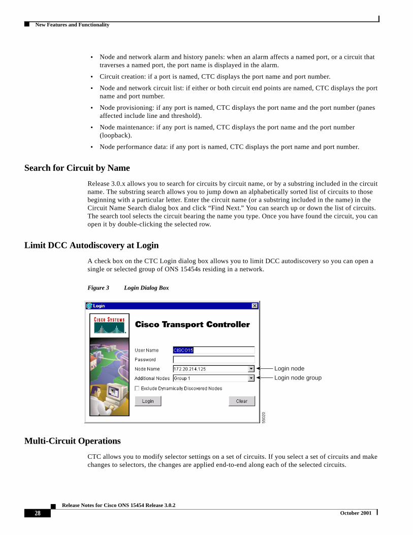
Limit DCC Autodiscovery at Login
A check box on the CTC Login dialog box allows you to limit DCC autodiscovery so you can opesingle or selected group of ONS 15454s residing in a network.
Figure 3 Login Dialog Box
Multi-Circuit Operations
CTC allows you to modify selector settings on a set of circuits. If you select a set of circuits and changes to selectors, the changes are applied end-to-end along each of the selected circuits.
Login node
Login node group
5502
0
28Release Notes for Cisco ONS 15454 Release 3.0.2
October 2001

New Features and Functionality
thereates
ountes, the
untsClear
rased.n, allsplay.
ioear-endcreen.
rased
ode isr
-over
nrrent
Auto Range
CTC also provides an auto-range feature that eliminates the need to individually build circuits of same type. Specify the number of circuits you need, create one circuit, and CTC automatically cadditional sequential circuits.
Baseline Button
In CTC Release 3.0 and higher, the Baseline button located on the far right of the PerformanceMonitoring screen clears the PM count displayed in the Current column, but does not clear the PM con the card. When the current 15-minute or 24-hour time interval passes or the screen view changtotal number of PM counts on the card and on the screen appear in the appropriate column.
Clear Button
The Clear button located on the far right of the Performance Monitoring screen clears certain PM codepending on the option selected. When the Clear button is clicked, three options appear in the Statistics menu: Selected interfaces, All interfaces on port x, and All interfaces on card.
When you clear selected interfaces, all PM counts associated with the selected radio buttons are eFor example, if the “15 min” and the Near End buttons are selected and you click the Clear buttonear-end PM counts in the current 15-minute interval are erased from the card and the screen di
When you clear all interfaces on port x, all PM counts associated with all combinations of the radbuttons on the selected port are erased from the card and the screen. This means the 15-minute nand far-end counts and 24-hour near-end and far-end counts are cleared from the card and the s
When you clear all interfaces on the card, PM counts for all data and ports on all interfaces are efrom the card and the screen.
Caution The Clear button can mask problems if used incorrectly. This button is commonly used fortesting purposes.
Note The Ethernet cards are the only cards without the Clear button option.
Active/Standby Indication
In node view, visual indication of the status (active vs. standby) of each card in an ONS 15454 nprovided. This allows you to view the status quickly, which is particularly helpful during a forced oautomatic protection switch. This feature enhances (but does not replace) the current mouse rollindication.
Filtering of Circuit View Window
In the CTC circuit window, you can filter circuits to the current network/node/card level. This optiorestricts the circuits listed to only those items meeting the filter criteria and associated with the cuview (for example, the circuits on the node or card being viewed).
29Release Notes for Cisco ONS 15454 Release 3.0.2
October 2001

New Features and Functionality
ure 4.
Any
larm
dd the
n
nderences
pecify
back.
CTC Preferences
Release 3.0.x allows you to set CTC preferences from a new Preferences dialog box, shown in Fig
Figure 4 Preferences Dialog Box
Change the CTC Network Image
The CTC Preferences dialog box allows you to change the image displayed in CTC network view.JPEG or GIF image accessible from a local or network drive can be used.
Limit History
The CTC Preferences dialog box allows you to modify the number of records shown in the CTC ahistory.
Access Non-DCC Connected ONS 15454 Networks
In previous CTC releases, access to non-DCC connected ONS 15454 networks required you to atopology host IP address to the cms.ini file. In Release 3.0.x, you can add the IP address(es) foradditional non-DCC connected networks to be managed by CTC. When you log into CTC, you caspecify which groups you want to access.
Modify Span Colors
The CTC Preferences dialog box allows you to modify the background and foreground of active astandby spans. Span colors can be selected from color swatches on the Circuit pane of the Prefdialog box.
Firewall Access
In Release 3.0.x, workstations can access the ONS 15454 using a firewall-compliant connection. Sthe port to connect through in the Firewall pane of the Preferences dialog box.
Loopback Indication
CTC provides a visual indication for ports, circuits, and circuit records that are involved in a loop
30Release Notes for Cisco ONS 15454 Release 3.0.2
October 2001

New Features and Functionality
rest
LANguredSPF).
hen
gh the
s andls and
an so
achross
d as
AutoDelete Cleared Alarms Checkbox
When you check AutoDelete Cleared Alarms, CTC remembers the setting between sessions.
Column Sizes
If you change the column width of table data in a CTC window, CTC will retain that width for the of the CTC session (unless you change it again). CTC Release 3.0.x allows the operator to saveindividual column widths for each type of table.
OSPF Support
Open Shortest Path First (OSPF) support allows OSPF hello notifications to be exposed through theinterface to external routers which automatically update their static route tables. OSPF can be confiso that OSPF routes are not displayed automatically. The default setting is off (not advertising O
Inhibit Switch to Protection Support
CTC reflects protection switches issued by TL1 commands. CTC also supports Lockout inhibition wset by TL1 or CTC.
Online Help
ONS 15454 Release 3.0 documentation can be viewed in an online help window accessed throuCTC Help menu. The help is installed from the ONS 15454 Release 3.0.x software CD or thedocumentation CD, using the new CTC Setup Wizard. The help window includes a table of contentan index in frames adjacent to the body text. It also provides access to PDF versions of the manuaa search tool.
GR-253 VT Renumbering
In accordance with Telcordia GR-253 Section 6.1.2 (R6-2), VT numbering within an STS-1 uses two-level Group number and VT number convention. Port numbers associated with VTs are showthat you do not need to look in the documentation for this mapping.
SONET/SDH Combination Card
CTC reflects each port’s mode configuration (SONET/SDH) visually in inventory and card view. Eport can be set to SDH or SONET. If a port is configured as SDH, CTC prevents VT and STS-1 cconnection.
For SDH, CTC functionally provides the same operation that was supported when the units wereconfigured for SONET services only.
Each port on all OC-12 cards (OC12 IR 1310, OC12 LR 1310, OC12 LR 1550) can be provisioneSTM-4. Each port on all OC-48 cards (OC48 IR 1310, OC48 LR 1310, OC48 LR 1550) can beprovisoned as STM-16.
All CTC fault management functions are provided for these cards.
31Release Notes for Cisco ONS 15454 Release 3.0.2
October 2001

New Features and Functionality
ode
for
tiond so
UPSRrtionsrkingsingle
se thedition,
NSed inshare
tagram is
s
Performance Management
All CTC performance management functionality:
• Provides for SDH
• Reports existing PM information (SONET and Async)
• Reports threshold crossing alarms
Configuration Management
• CTC graphically and visually designates the SDH/SONET combo card and each port’s current m(SONET or SDH mode).
• CTC supports the ability to cross connect an STM circuit to an appropriate size STS circuit (example, STM1 to STS-3C).
• CTC circuit management functionality provides for SDH circuits.
• To provision an SDH circuit, an appropriate STS-N circuit is defined. The section and lineinformation on the inbound signal will be terminated. The STS-N carries the SDH path informaand SDH payload. At the SDH handoff, SDH section and line header information is reintroducethat an SDH signal departs.
Node Diversity
Release 3.0.x supports node diversity as an option during automated circuit provisioning across segments in a mesh (PPMN) network. This option does not apply to 1:1, unprotected, and BLSR poof the network. Node diversity means that, except for the source and destination, the circuit’s woand protect paths do not traverse any of the same nodes. This feature ensures that the failure of anode will not eliminate the benefit of SONET protection.
DHCP Pass-through Support
Release 3.0.x allows Dynamic Host Configuration Protocol (DHCP) requests/responses to traverONS 15454 network. This allows craft PCs to request and receive appropriate IP addresses. In adthe combination of DHCP pass-through and Proxy ARP allows the craft PC to work without any O15454 or PC configuration in most subnetting environments. With the static route support introducRelease 2.1, the craft PC can work with an ONS 15454 even when multiple nodes on the same DCCa subnet and other crafts are connected. DHCP pass-through support includes support for User DaProtocol (UDP) and listening on Port 67 (the standard BOOTP/DHCP port). DHCP pass-throughconfigured as “on” or “off” in CTC; the default is “off.”
Lamp Test
You can activate ONS 15454 lamp tests from CTC. When the test is invoked, all ONS 15454 LEDilluminate at the same time for 10 seconds. Bicolored LEDs cycle from green to yellow.
Improved Management Routing
The following improvements have been made to management routing:
32Release Notes for Cisco ONS 15454 Release 3.0.2
October 2001

New Features and Functionality
o addIPnfigure
r a
15454). Thist
nel is
are
des it
ord) ates.
rcuits
and
• Route advertisement over LAN interface: the surface mechanism (OSPF) eliminates the need tto static route tables in an affiliate router when a Cisco ONS ring is deployed. Only the node address is sent to external systems via OSPF; IP addresses on cards are not sent. You can coOSPF so that node IPs are not sent. The default configuration is off (not advertising OSPF).
• Craft attachment: Craft attachment and management of all nodes on a DCC (regardless ofsubnetting) without the addition of static routes to the craft PC is now possible. Proxy ARP osimilar mechanism over a LAN interface is supported to provide this capability. Multiple craftattachments to the same DCC can occur at the same time.
• Route learning and aging support: redundant physical connections to an ONS 15454 ring aresupported, including rerouting messages through an alternate route and/or an alternate ONSgateway. Nodes can reroute messages (including the primary and secondary gateway nodesfeature is not affected by subnet configuration (all nodes on one subnet, all nodes on differensubnets, or any combination).
Improved GUI on Circuit Creation Wizard
A panel was added to the Circuit Creation Wizard to record entries from previous pages. This pavisible during the selection process and displays user selections.
Network Topology Map
In Release 3.0.x, you can use a Zoom command to change the network topology map display:
• You can store a preferred zoom configuration as the default map view.
• When you zoom in or out, nodes are repositioned so that DCC spans do not overlap. DCCs clearly delineated while nodes retain their geographic positions (as placed by the user orlongitude/latitude coordinates).
• With zooming, it is possible to see and select one of up to ten DCC spans.
• The size of the ONS 15454 icon has been reduced to allow for more nodes in a view.
Common Security Profiles
CTC allows user security information (userid, password, permissions) to be shared across the nomanages:
• You can set SNMP community strings and access privileges.
• You can perform user management operations (such as creating a user or changing a passwthe network level. When a change is made on this screen, it applies to all CTC-managed nod
Multiple Circuit Creation
You can define multiple circuits between the same nodes in one easy step using the Number of Cifield in the Circuit Provisioning Wizard.
CTC Managed Software Download
CTC Managed Software Download allows you to download CTC software to multiple nodes seriallyin parallel.
33Release Notes for Cisco ONS 15454 Release 3.0.2
October 2001

New Features and Functionality
ional
out
or. A new the
hanger to the
Any
ntersnd thatecial
on andENE.e ENE
Note Cisco advises that you limit concurrent software downloads to 3 nodes at once.
Directional Arrows on Circuit Maps
Arrowheads have been added to circuit lines displayed on the circuit map to distinguish unidirectand bidirectional circuits.
TL1
CTAGs
In accordance with Telcordia GR-831, all TL1 commands must include a CTAG. Commands withCTAGs will be rejected by TL1 with the error Invalid Correlation Tag (IICT).
Password Enforcement
In accordance with Telcordia GR-815, TL1 functionality for Release 3.0.2 enforces passwordcomplexity as follows.
ONS 15454 TL1 enforces password complexity for TL1 and users. This rule only applies for newchanged passwords after Release 3.0.2 is installed; existing passwords do not need to be changedpassword must have at least 1 numeric character (0 to 9) and at least one special character fromcharacter set {plus-sign (+), pound-sign (#), percent-sign (%)}.
Note See the “DDTS # CSCdv62990” section on page 12 for a CTC caveat to these rules.
Test Access
TL1 Test Access enables you to monitor and test circuits. Commands to connect, disconnect and cthe test access (TACC) and test access connections have been added to TL1 for Release 3.0. RefeTL1 Command Guide, Release 3.0 for more information.
Gateway Network Element Topology
TL1 Gateway enables you to issue TL1 commands to multiple nodes using a single connection. node can serve as a Gateway Network Element (GNE), End-Point Network Element (ENE), orIntermediate Network Element (INE). A node becomes a GNE when a TL1 user connects to it and ea command destined for another node. An ENE is an end node because it processes a TL1 commais passed to it from another node. An INE is an intermediate node because of topology; it has no sphardware, software, or provisioning.
The GNE Session is the connection that multiplexes TL1 messages between the OSS/craftspersthe GNE. The GNE demulitplexes incoming OSS TL1 commands and forwards them to the remoteThe GNE also multiplexes incoming responses and autonomous messages to the GNE Session. ThSession is the connection that exchanges messages between the GNE and the remote ENE.
34Release Notes for Cisco ONS 15454 Release 3.0.2
October 2001

New Features and Functionality
n OS and
Each GNE can support six (5+1) concurrent gateway communication sessions (connections from ato the GNE). Five of these sessions are via the LAN (wire-wrap, active TCC+ LAN port, or DCC)the sixth session is reserved for the active TCC+ serial port.
New AIDs
TL1 supports the following new AIDs as of Release 3.0.
• BLSR
• ALL (added to the VT1_5 AID table)
Parameter Value Changes
TL1 supports the following parameter value changes as of Release 3.0.
• TMPER input/output value changed from 15MIN to 15-MIN
• SENDDONOTUSE changed to SENDDUS
• BLSR_MODE (new parameter)
• BLSR_TYPE (new parameter)
• MOD-TACC
• TACC-MODE
New Conditions
TL1 supports the following new conditions as of Release 3.0.
• NHSWPR - Inhibit switch to protect request on equipment
• NHSWWKG - Inhibit switch to working request on equipment
The following new BER alarm conditions have been added:
Conditions Replaced in Release 3.0
The SWFTDWN condition has been changed to SFTWDOWN.
Condition Alarm Description Type
SD-L BER Threshold exceeded forSignal Degrade
Line
SD-P BER Threshold exceeded forSignal Degrade
Path
SF-L BER Threshold exceeded forSignal Failure
Line
SF-P BER Threshold exceeded forSignal Failure
Path
35Release Notes for Cisco ONS 15454 Release 3.0.2
October 2001
New Features and Functionality
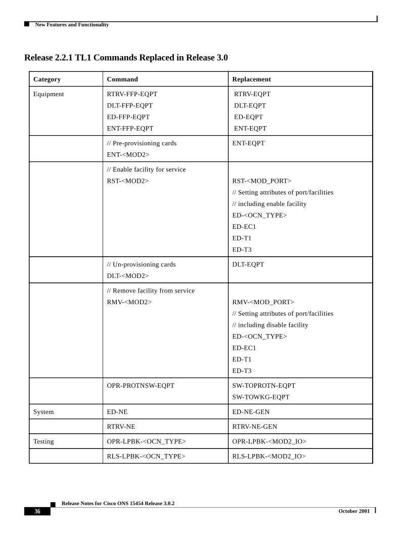
Release 2.2.1 TL1 Commands Replaced in Release 3.0
Category Command Replacement
Equipment RTRV-FFP-EQPT
DLT-FFP-EQPT
ED-FFP-EQPT
ENT-FFP-EQPT
RTRV-EQPT
DLT-EQPT
ED-EQPT
ENT-EQPT
// Pre-provisioning cards
ENT-<MOD2>
ENT-EQPT
// Enable facility for service
RST-<MOD2> RST-<MOD_PORT>
// Setting attributes of port/facilities
// including enable facility
ED-<OCN_TYPE>
ED-EC1
ED-T1
ED-T3
// Un-provisioning cards
DLT-<MOD2>
DLT-EQPT
// Remove facility from service
RMV-<MOD2> RMV-<MOD_PORT>
// Setting attributes of port/facilities
// including disable facility
ED-<OCN_TYPE>
ED-EC1
ED-T1
ED-T3
OPR-PROTNSW-EQPT SW-TOPROTN-EQPT
SW-TOWKG-EQPT
System ED-NE ED-NE-GEN
RTRV-NE RTRV-NE-GEN
Testing OPR-LPBK-<OCN_TYPE> OPR-LPBK-<MOD2_IO>
RLS-LPBK-<OCN_TYPE> RLS-LPBK-<MOD2_IO>
36Release Notes for Cisco ONS 15454 Release 3.0.2
October 2001

New Features and Functionality
e
.
e
trae
ect
hss.
Release 2.2.1 TL1 Commands Changed in Release 3.0
TL1 COMMAND DESCRIPTION OF CHANGES
ALW-MSG-ALL
INH-MSG-ALL
The two commas at the end of the command are not needed anymore.
ALW-SWDX-EQPT Semi-colons after the CTAG field are not required anymore.
DLT-CRS-<STS_PATH>
DLT-CRS-VT1
Trailing semi-colons after the CTAG are optional.
ED-BITS Added support for the Sync Message field. An extra colon is needed after CTAGfield. The colon after the PST field is not necessary. The Name string in Name/Valuparameter changed.
ED-EC1 Added support for the Rx Equalization attribute for an EC1 port. The extra colonafter the PST field is not required anymore.
ED-T1 Removed support for the ID field. Three colons after the CTAG field are nowrequired, instead of two. The extra colon after the PST field is not required anymoreAdded support for Test Access.
ED-T3 Three colons are needed after CTAG field, instead of two. The extra colon after thPST field is not required anymore. Added support for Test Access.
ED-<OCN_TYPE> Added support for the send DUS and Synchronous Status Message fields. The excolon after the PST field is not required anymore. Three colons are needed after thCTAG field instead of two.
ENT-CRS-<STS_PATH> Cross-connect types are optional. The default is 2WAY. Supported Cross Conntypes are now limited to 1WAY and 2WAY.
ENT-FFP-<OCN_TYPE>
ED-FFP-<OCN_TYPE>
An extra colon after the CTAG field is required. Name field in name/valueparameters have changed.
ED-EQPT
ENT-EQPT
RTRV-EQPT
This family of commands was functionally expanded to edit/enter/retrieveequipment attributes and electrical 1:1 and 1:N Protection Group. Use thesecommands instead of ED/ENT/RTRV-FFP-EQPT.
ED-USER-SECU Added support for a NEW USER ID field. Fields are now positional instead ofname/value pairs.
ENT-USER-SECU An extra comma is needed after the PASSWORD field.
ED-<STS_PATH> Added support for following fields: Revertive Mode, Revertive Time, Expected PatTrace, Path Trace Message, and Path Trace Mode. Added support for Test Acce
INIT-SYS Phase Field (Level of Initialization) is not supported anymore.
OPR-LPBK-<MOD2_IO>
RLS-LPBK-<MOD2_IO>
The Loopback Type field is now optional.
37Release Notes for Cisco ONS 15454 Release 3.0.2
October 2001

New Features and Functionality
,
OPR-PROTNSW-<OCN_TYPE> Added support for the SWITCH command field.
INIT-REG-<MOD2>
RTRV-PM-<MOD2>
Added support for an optional Location field. Now only one comma is needed(instead of two) after the Time Period field.
REPT ALM BITS
REPT ALM SYNCN
Output – The Condition description field is now optional.
REPT ALM <MOD2ALM>
REPT ALM EQPT
REPT EVT <MOD2ALM>
The Description and Equipment Type fields are now optional.
REPT ALM EVT The positions of the Description and Equipment Type fields have changed.
REPT EVT SYNCN Output – Condition and Condition Description are now optional. Requires 7commas (instead of 6) after the Condition Effect field. Added support for the AidType field.
RTRV-ALM-BITS
RTRV-ALM-SYNCN
Output – Added support for the Aid Type field.
RTRV-BITS Output – Added support for the Sync Messaging field.
RTRV-COND-ALL One less comma is needed after the Condition field.
RTRV-COND-BITS
RTRV-COND-SYNCN
Requires two commas (instead of three) after the Condition field.
RTRV-CRS-<STS_PATH>
RTRV-CRS-VT1
Semi-colons after the CTAG are no longer required.
RTRV-ALM-EQPT
RTRV-COND-EQPT
RTRV-ALM-MOD2
RTRV-COND-MOD2
RTRV-ALM-ALL
Use one less comma after the Service Affect field.
RTRV-EC1 The four colons after the CTAG field are now optional.Output – Added support for the Rx Equalization field.
RTRV-FFP-EQPT Output – Name field in Name/Value parameters changed.
RTRV-INV Output – Requires two colons (instead of one) after the Aid Type field.
RTRV-LOG Requires an additional logname field.
RTRV-<OCN_TYPE> The four colons after the CTAG field are now optional.Output – Added support for the following fields: Sync Status Messaging, Send DUSRing ID, and BLSR Type. Dropped support for Revertive Time.
38Release Notes for Cisco ONS 15454 Release 3.0.2
October 2001

New Features and Functionality
,ode
s
to
TL1 Commands New in Release 3.0
Note Refer to the TL1 Command Guide for new command descriptions.
RTRV-<STS_PATH> Output – Added support for the following fields: Revertive Mode, Revertive TimeExpected Path Trace, Path Trace Message, Incoming Path Trace, Path Trace Mand Test Access.
RTRV-SYNCN Output – Replaced the Primary, Secondary, and Third fields with Rank ofSynchronization Reference, Value of a Sync Ref, Quality of Sync Source, and Statuof Signal Source.
RTRV-TOD Output – Requires one comma (instead of two) after the Seconds field.
RTRV-T1
RTRV-T3
The four colons after the CTAG field are now optional.Output – Dropped support for the ID field.
SET-TOD The Name string in the Name/Value parameter has been changed from USEDSTDST
SW-DX-EQPT The comma after the optional Mode field is no longer necessary.
CATEGORY COMMAND
BLSR ED-BLSR
RTRV-BLSR
ENVIRONMENT RTRV-ATTR-CONT
RTRV-ATTR-ENV
RTRV-EXT-CONT
SET-ATTR-CONT
SET-ATTR-ENV
OPR-EXT-CONT
RLS-EXT-CONT
EQUIPMENT ALW-SWTOPROTN-EQPT
ALW-SWTOWKG-EQPT
INH-SWTOPROTN-EQPT
INH-SWTOWKG-EQPT
SW-SWTOPROTN-EQPT
SW-SWTOWKG-EQPT
ED-EQPT
INH-SWDX-EQPT
39Release Notes for Cisco ONS 15454 Release 3.0.2
October 2001

New Features and Functionality
FAULT REPT ALM COM // Autonomous message
PERFORMANCE RTRV-PMMODE-<STS_PATH>
SET-PMMODE-<STS_PATH>
SECURITY REPT EVT SECU // Autonomous message
CANC // Autonomous message
SYNCHRONIZATION OPR-SYNCSW
RLS-SYNCSW
SYSTEM ED-NE-GEN
CHG-ACCMD-<MOD_TACC>
CONN-TACC-<MOD_TACC>
DISC-TACC
RTRV-NE-GEN
RTRV-NE-IPMAP
PORTS RMV-<MOD_PORT>
RST-<MOD_PORT>
STS & VT PATHS RTRV-PHTRC-<STS_PATH>
ED-VT1
RTRV-VT1
SYNCHRONIZATION ED-NE-SYNCN
RTRV-NE-SYNCN
UPSR SWITCHING OPR-PROTNSW-<STS_PATH>
OPR-PROTNSW-VT1
RLS-PROTNSW-<STS_PATH>
RLS-PROTNSW-VT1
REPT SW // Autonomous message
40Release Notes for Cisco ONS 15454 Release 3.0.2
October 2001
Related Documentation
ites:
tionmoret
cess, or
ptical
tive by, by
Related Documentation• Cisco ONS 15454 Installation and Operations Guide, Release 3.0
• Cisco ONS 15454 Troubleshooting and Reference Guide, Release 3.0
• Cisco ONS 15454 TL1 Command Guide, Release 3.0
• Cisco ONS 15454 Product Overview, Release 3.0
• Release Notes for the Cisco ONS 15454, Release 3.0
Obtaining DocumentationThe following sections provide sources for obtaining documentation from Cisco Systems.
World Wide WebYou can access the most current Cisco documentation on the World Wide Web at the following s
• http://www.cisco.com
• http://www-china.cisco.com
• http://www-europe.cisco.com
Optical Networking Product Documentation CD-ROMOptical networking-related documentation, including theCisco ONS 15454 Release Notes, is availablein a CD-ROM package that ships with your product. The Optical Networking Product DocumentaCD-ROM, a member of the Cisco Connection Family, is updated as required. Therefore, it might becurrent than printed documentation. To order additional copies of the Optical Networking ProducDocumentation CD-ROM, contact your local sales representative or call customer service. TheCD-ROM package is available as a single package or as an annual subscription. You can also acCisco documentation on the World Wide Web at http://www.cisco.com, http://www-china.cisco.comhttp://www.europe.cisco.com.
Ordering DocumentationCisco documentation is available in the following ways:
• Registered Cisco Direct Customers can order Cisco Product documentation, including the ONetworking Product CD-ROM from the Networking Products MarketPlace:
http://www.cisco.com/cgi-bin/order/order_root.pl
• Nonregistered Cisco.com users can order documentation through a local account representacalling Cisco corporate headquarters (California, USA) at 408 526-7208 or, in North Americacalling 800 553-NETS(6387).
41Release Notes for Cisco ONS 15454 Release 3.0.2
October 2001

Obtaining Technical Assistance
al
nt, or
s can.com
open
mlineisco
s withls andlable.
n andupport,
oduct
Documentation FeedbackIf you are reading Cisco product documentation on the World Wide Web, you can submit techniccomments electronically. ClickFeedbackin the toolbar and selectDocumentation. After you completethe form, clickSubmit to send it to Cisco.
You can e-mail your comments to [email protected].
To submit your comments by mail, use the response card behind the front cover of your documewrite to the following address:
Attn Document Resource ConnectionCisco Systems, Inc.170 West Tasman DriveSan Jose, CA 95134-9883
We appreciate your comments.
Obtaining Technical AssistanceCisco provides Cisco.com as a starting point for all technical assistance. Customers and partnerobtain documentation, troubleshooting tips, and sample configurations from online tools. For Ciscoregistered users, additional troubleshooting tools are available from the TAC website.
Cisco.comCisco.com is the foundation of a suite of interactive, networked services that provides immediate,access to Cisco information and resources at anytime, from anywhere in the world. This highlyintegrated Internet application is a powerful, easy-to-use tool for doing business with Cisco.
Cisco.com provides a broad range of features and services to help customers and partners streabusiness processes and improve productivity. Through Cisco.com, you can find information about Cand our networking solutions, services, and programs. In addition, you can resolve technical issueonline technical support, download and test software packages, and order Cisco learning materiamerchandise. Valuable online skill assessment, training, and certification programs are also avai
Customers and partners can self-register on Cisco.com to obtain additional personalized informatioservices. Registered users can order products, check on the status of an order, access technical sand view benefits specific to their relationships with Cisco.
To access Cisco.com, go to the following website:
http://www.cisco.com
Technical Assistance CenterThe Cisco TAC website is available to all customers who need technical assistance with a Cisco pror technology that is under warranty or covered by a maintenance contract.
42Release Notes for Cisco ONS 15454 Release 3.0.2
October 2001

Obtaining Technical Assistance
ost
asic
.
users
ing
e is
ness
r
ration,
ot imply
Contacting TAC by Using the Cisco TAC Website
If you have a priority level 3 (P3) or priority level 4 (P4) problem, contact TAC by going to the TACwebsite:
http://www.cisco.com/tac
P3 and P4 level problems are defined as follows:
• P3—Your network performance is degraded. Network functionality is noticeably impaired, but mbusiness operations continue.
• P4—You need information or assistance on Cisco product capabilities, product installation, or bproduct configuration.
In each of the above cases, use the Cisco TAC website to quickly find answers to your questions
To register for Cisco.com, go to the following website:
http://www.cisco.com/register/
If you cannot resolve your technical issue by using the TAC online resources, Cisco.com registeredcan open a case online by using the TAC Case Open tool at the following website:
http://www.cisco.com/tac/caseopen
Contacting TAC by Telephone
If you have a priority level 1 (P1) or priority level 2 (P2) problem, contact TAC by telephone andimmediately open a case. To obtain a directory of toll-free numbers for your country, go to the followwebsite:
http://www.cisco.com/warp/public/687/Directory/DirTAC.shtml
P1 and P2 level problems are defined as follows:
• P1—Your production network is down, causing a critical impact to business operations if servicnot restored quickly. No workaround is available.
• P2—Your production network is severely degraded, affecting significant aspects of your busioperations. No workaround is available.
This document is to be used in conjunction with the Cisco ONS 15454 User Documentation.
AccessPath, AtmDirector, Browse with Me, CCIP, CCSI, CD-PAC,CiscoLink, the CiscoPowered Network logo, Cisco Systems NetworkingAcademy, the Cisco Systems Networking Academy logo, Fast Step, Follow Me Browsing, FormShare, FrameShare, GigaStack, IGX, IntenetQuotient, IP/VC, iQ Breakthrough, iQ Expertise, iQ FastTrack, the iQ Logo, iQ Net Readiness Scorecard, MGX, the Networkers logo, Packet,RateMUX, ScriptBuilder, ScriptShare, SlideCast, SMARTnet, TransPath, Unity, Voice LAN, Wavelength Router, and WebViewer are trademarksof Cisco Systems, Inc.; Changing the Way We Work, Live, Play, and Learn, Discover All That’s Possible, and Empowering the Internet Geneare service marks of Cisco Systems, Inc.; and Aironet, ASIST, BPX, Catalyst, CCDA, CCDP, CCIE, CCNA, CCNP, Cisco, the Cisco CertifiedInternetwork Expert logo, Cisco IOS, the Cisco IOS logo, Cisco Press, Cisco Systems, Cisco Systems Capital, the Cisco Systems logo,Enterprise/Solver, EtherChannel, EtherSwitch, FastHub, FastSwitch, IOS, IP/TV, LightStream, MICA, Network Registrar, PIX, Post-Routing,Pre-Routing, Registrar, StrataView Plus, Stratm, SwitchProbe, TeleRouter, and VCO are registered trademarks of Cisco Systems, Inc. and/or itsaffiliates in the U.S. and certain other countries.
All other trademarks mentioned in this document or Web site are the property of their respective owners. The use of the word partner does na partnership relationship between Cisco and any other company. (0108R)
Copyright © 2001, Cisco Systems, Inc.All rights reserved.
43Release Notes for Cisco ONS 15454 Release 3.0.2
October 2001

Obtaining Technical Assistance
44Release Notes for Cisco ONS 15454 Release 3.0.2
October 2001