reinforced concrete by peter w. somers, s.e.€¦ · · 2018-04-04reinforced concrete by peter w....
TRANSCRIPT

Reinforced Concrete - 1Instructional Materials Complementing FEMA P-1051, Design Examples
Disclaimer
7 Reinforced Concrete
By Peter W. Somers, S.E. Originally developed by Finley A. Charney, PhD, P.E.

Reinforced Concrete - 2Instructional Materials Complementing FEMA P-1051, Design Examples
• Concrete and reinforcement behavior • Reference standards• Requirements by Seismic Design Category
– Moment resisting frames– Shear walls
• Other topics• Design Examples
Topic Overview

Reinforced Concrete - 3Instructional Materials Complementing FEMA P-1051, Design Examples
• Concrete and reinforcement behavior • Reference standards• Requirements by Seismic Design Category
– Moment resisting frames– Shear walls
• Other topics• Design Examples
Topic Overview

Reinforced Concrete - 4Instructional Materials Complementing FEMA P-1051, Design Examples
• Compressive Ductility– Strong in compression but brittle– Confinement improves ductility by
• Maintaining concrete core integrity• Preventing longitudinal bar buckling
• Flexural Ductility– Longitudinal steel provides monotonic ductility at low
reinforcement ratios– Transverse steel needed to maintain ductility through
reverse cycles and at very high strains (hinge development)
Summary of Concrete Behavior

Reinforced Concrete - 5Instructional Materials Complementing FEMA P-1051, Design Examples
• Concrete and reinforcement behavior• Reference standards• Requirements by Seismic Design Category
– Moment resisting frames– Shear walls
• Other topics• Design Examples
Topic Overview

Reinforced Concrete - 6
16
Instructional Materials Complementing FEMA P-1051, Design Examples
Reference Standards

Reinforced Concrete - 7Instructional Materials Complementing FEMA P-1051, Design Examples
Modifications to Reference Standards

Reinforced Concrete - 8Instructional Materials Complementing FEMA P-1051, Design Examples
Provisions ASCE 7-16 ACI 318-14
ASCE 7-16 for ConcreteStructural design criteria: Chap. 12Structural analysis procedures: Chap. 12Design of concrete structures: Sec. 14.2
Provisions modifications to ASCE 7-10ASCE 7-16 modifications to ACI 318-14
Context in NEHRP Recommended Provisions

Reinforced Concrete - 9Instructional Materials Complementing FEMA P-1051, Design Examples
ASCE 7-16:Defines systems and classificationsProvides design coefficients
ACI 318-14:Provides system design and detailingrequirements consistent with ASCE 7-16
system criteria Modified by ASCE 7-16
Reference Standards

Reinforced Concrete - 10Instructional Materials Complementing FEMA P-1051, Design Examples
• ACI 318– Chapter 18, Earthquake-Resistant Structures
• ASCE 7-16 and Provisions Section 14.2– Modifications to ACI 318– Detailing requirements for concrete piles
• Provisions supersede ASCE 7-10 modifications
Use of Reference Standards

Reinforced Concrete - 11Instructional Materials Complementing FEMA P-1051, Design Examples
• Wall piers and wall segments• Members not designated as part of the LRFS• Columns supporting discontinuous walls• Intermediate precast walls• Plain concrete structures• Anchoring to concrete• Foundations• Acceptance criteria for validation testing of
special precast walls
Detailed Modifications to ACI 318

Reinforced Concrete - 12Instructional Materials Complementing FEMA P-1051, Design Examples
• Concrete and reinforcement behavior • Reference standards• Requirements by Seismic Design Category
– Moment resisting frames– Shear walls
• Other topics• Design Examples
Topic Overview

Reinforced Concrete - 13Instructional Materials Complementing FEMA P-1051, Design Examples
Seismic ForceResisting System
Response Modification Coefficient, R
Deflection Amplification
Factor, Cd
Special R/C Moment Frame 8 5.5
Intermediate R/CMoment Frame
5 4.5
Ordinary R/CMoment Frame
3 2.5
Design Coefficients Moment Resisting Frames

Reinforced Concrete - 14Instructional Materials Complementing FEMA P-1051, Design Examples
• Special Moment Frames– Strong column
• Avoid story mechanism– Hinge development
• Confined concrete core• Prevent rebar buckling• Prevent shear failure
– Member shear strength– Joint shear strength– Rebar development and splices (confined)
Performance Objectives

Reinforced Concrete - 15Instructional Materials Complementing FEMA P-1051, Design Examples
• Intermediate Moment Frames– Avoid shear failures in beams and columns– Plastic hinge development in beams and columns– Toughness requirements for two-way slabs without
beams• Ordinary Moment Frames
– Minimum ductility and toughness– Continuous top and bottom beam reinforcement– Minimum column shear failure protection
Performance Objectives

Reinforced Concrete - 16Instructional Materials Complementing FEMA P-1051, Design Examples
Issue Ordinary Intermediate Special
Hinge development and confinement minor full
Bar buckling lesser full
Member shear lesser full
Joint shear minor minor full
Strong column full
Rebar development lesser lesser full
Load reversal minor lesser full
Summary of Seismic Detailing for Frames

Reinforced Concrete - 17Instructional Materials Complementing FEMA P-1051, Design Examples
• General detailing requirements• Beams• Joints• Columns• Example problem
Special Moment Frames

Reinforced Concrete - 18Instructional Materials Complementing FEMA P-1051, Design Examples
Story mechanism Sway mechanism
Frame Mechanisms“strong column – weak beam”

Reinforced Concrete - 19Instructional Materials Complementing FEMA P-1051, Design Examples
nbnc M2.1MM
M
M
M
nc1
nc2
nb2nb1
Required Column Strength

Reinforced Concrete - 20Instructional Materials Complementing FEMA P-1051, Design Examples
• Tightly Spaced Hoops – Provide confinement to increase concrete strength
and usable compressive strain– Provide lateral support to compression bars to
prevent buckling– Act as shear reinforcement and preclude shear
failures– Control splitting cracks from high bar bond stresses
Hinge Development

Reinforced Concrete - 21Instructional Materials Complementing FEMA P-1051, Design Examples
Splice away from hinges andenclose within hoops or spirals
Joint face Mn+ not less than 50% Mn
-
Min. Mn+ or Mn
- not less than25% max. Mn at joint face
At least 2 bars continuoustop & bottom
025.0200 yf
ACI 318, Overview of SMF:Beam Longitudinal Reinforcement

Reinforced Concrete - 22Instructional Materials Complementing FEMA P-1051, Design Examples
Longitudinal bars on perimetertied as if column bars
Stirrups elsewhere, s d/22hmin
Closed hoops at hinging regionswith “seismic” hook
135º hook, 6dh 3” extension
Maximum spacing of hoops:
d/4 6db 6”
ACI 318, Overview of SMF:Beam Transverse Reinforcement

Reinforced Concrete - 23Instructional Materials Complementing FEMA P-1051, Design Examples
ACI 318, Overview of SMF:Beam Shear Strength
analysisbyVe
20
2wMM
V nu
n
2pr1pre
0.1,f25.1f
withMM
ys
npr
Mpr2Mpr1
Ve1 Ve2
1.2D + 1.0L + 0.2S
n
fAPuand
V21
'cg
e
then Vc = 0
If earthquake-inducedshear force

Reinforced Concrete - 24Instructional Materials Complementing FEMA P-1051, Design Examples
CTVcol
Vj
bottom,sy
top,sy
colj
Af25.1C
Af25.1T
VCTV
ACI 318, Overview of SMF:Beam-Column Joint

Reinforced Concrete - 25Instructional Materials Complementing FEMA P-1051, Design Examples
• Vn often controls size of columns• Coefficient depends on joint confinement• To reduce shear demand, increase beam depth• Keep column stronger than beam
jcn A'f121520
V
ACI 318, Overview of SMF: Beam-column Joint

Reinforced Concrete - 26Instructional Materials Complementing FEMA P-1051, Design Examples
Spacing shall not exceed the smallest of:b/4 or 6 db or so (4” to 6”)
Distance between longitudinal bas supported by hoops or cross ties, hx 14”
3
h144s xo
hx hx
ACI 318, Overview of SMF: Column Transverse Reinforcement at Potential Hinging Region

Reinforced Concrete - 27Instructional Materials Complementing FEMA P-1051, Design Examples
• Concrete and reinforcement behavior • Reference standards• Requirements by Seismic Design Category
– Moment resisting frames– Shear walls
• Other topics• Design Examples
Topic Overview

Reinforced Concrete - 28Instructional Materials Complementing FEMA P-1051, Design Examples
Seismic ForceResisting System
ResponseModification
Coefficient, R
Deflection Amplification
Factor, Cd
Special R/C Structural Walls 5 5
Ordinary R/CStructural Walls
4 4
Intermediate PrecastStructural Walls
4 4
Ordinary Precast Walls 3 3
Design CoefficientsStructural Walls (Bearing Systems)

Reinforced Concrete - 29Instructional Materials Complementing FEMA P-1051, Design Examples
• Special R/C structural walls– Resist axial forces, flexure and shear – Boundary members
• Where compression stress/strain is large, maintain capacity
– Development of rebar in panel– Ductile coupling beams
• Ordinary R/C structural walls– No seismic requirements, Ch. 18 does not apply
Performance Objectives

Reinforced Concrete - 30Instructional Materials Complementing FEMA P-1051, Design Examples
• Flexural yielding will occur in predetermined flexural hinging regions
• Brittle failure mechanisms will be precluded– Diagonal tension– Sliding hinges– Local buckling– Shear failures in coupling beams
Design Philosophy

Reinforced Concrete - 31Instructional Materials Complementing FEMA P-1051, Design Examples
w
hw
Shear plane, Acv =web thickness x length of wall
= perpendicularto shear plane
t = parallel to shear plane
ACI 318, Overview of Special Walls:General Requirements

Reinforced Concrete - 32Instructional Materials Complementing FEMA P-1051, Design Examples
ccvu fAV '
• and t not less than 0.0025 unless
then per Sec.11.6• Spacing not to exceed 18 in.• Reinforcement contributing to Vn shall be
continuous and distributed across the shear plane
ACI 318, Overview of Special Walls:General Requirements

Reinforced Concrete - 33Instructional Materials Complementing FEMA P-1051, Design Examples
ccvu fAV '2
• Two curtains of reinforcing required if:
• Design shear force determined from lateral load analysis
ACI 318, Overview of Special Walls:General Requirements

Reinforced Concrete - 34
ACI 318, Overview of Special Walls:General Requirements
• Shear strength:
• Walls must have reinforcement in two orthogonal directions
ytcccvn ffAV '
c = 3.0 for hw/w1.5c = 2.0 for hw/w2.0Linear interpolation between
Instructional Materials Complementing FEMA P-1051, Design Examples

Reinforced Concrete - 35Instructional Materials Complementing FEMA P-1051, Design Examples
PM
• For axial load and flexure, design like a column to determine axial load – moment interaction
ACI 318, Overview of Special Walls:General Requirements

Reinforced Concrete - 36Instructional Materials Complementing FEMA P-1051, Design Examples
Extra confinement and/orlongitudinal bars at end
Widened end with confinement
For walls with a high compression demand at the edges – specialboundary elements are required
ACI 318, Overview of Special Walls:Boundary Elements

Reinforced Concrete - 37Instructional Materials Complementing FEMA P-1051, Design Examples
Two options for determining need for boundary elements
• Strain-based: Determined using wall deflection and associated wall curvature
• Stress-based: Determined using maximum extreme fiber compressive
ACI 318: Overview of Special WallsBoundary Elements

Reinforced Concrete - 38Instructional Materials Complementing FEMA P-1051, Design Examples
w
u
w
h
c5.1600
• Boundary elements are required if:
u = Design displacementc = Depth to neutral axis from strain
compatibility analysis with loads causing u
ACI 318, Overview of Special Walls:Boundary Elements—Strain

Reinforced Concrete - 39
ACI 318, Overview of Walls:Boundary Elements—Strain
• Where required, boundary elements must extend up the wall from the critical section a distance not less than the larger of:
w or Mu/4Vu
Instructional Materials Complementing FEMA P-1051, Design Examples

Reinforced Concrete - 40Instructional Materials Complementing FEMA P-1051, Design Examples
• Boundary elements are required where the maximum extreme fiber compressive stress calculated based on factored load effects, linear elastic concrete behavior and gross section properties, exceeds 0.2f’c
• Boundary element can be discontinued where the compressive stress is less than 0.15f’c
ACI 318: Overview of WallsBoundary Elements—Stress

Reinforced Concrete - 41Instructional Materials Complementing FEMA P-1051, Design Examples
• Boundary elements must extend horizontally not less than the larger of c/2 or c-0.1w
• Width of boundary elements, b > hu/16 or 12”• In flanged walls, boundary element must include all
of the effective flange width and at least 12 in. of the web
• Transverse reinforcement must extend into the foundation
• Horizontal reinforcement shall extend into the core of boundary and anchored to develop fy.
ACI 318: Overview of WallsBoundary Elements—Detailing

Reinforced Concrete - 42Instructional Materials Complementing FEMA P-1051, Design Examples
Standard or diagonalOther cases
Reinforce with 2 intersecting groups of diagonal bars
cwcun AfVh '4 and 2/
Design as Special Moment Frame beam
4/ hn
Requirements based on aspect ratio and shear demand
ACI 318: Overview of Walls Coupling Beams

Reinforced Concrete - 43Instructional Materials Complementing FEMA P-1051, Design Examples
• Concrete and reinforcement behavior • Reference standards• Requirements by Seismic Design Category
– Moment resisting frames– Shear walls
• Other topics• Design Examples
Topic Overview
Reinforced Concrete - 44Instructional Materials Complementing FEMA P-1051, Design Examples
• In frame members not designated as part of the lateral-force-resisting system in regions of high seismic risk:– Must be able to support gravity loads while subjected
to the design displacement– Transverse reinforcement increases depending on:
Forces induced by driftAxial force in member
Members Not Part of LFRS

Reinforced Concrete - 45Instructional Materials Complementing FEMA P-1051, Design Examples
Ductile connections• Inelastic action at field
splice
Strong connections• Configure system so that hinges
occur in factory cast members away from field splices
Field connections must yield
Field connectionsat points of lowstress
Precast Concrete:Performance Objectives

Reinforced Concrete - 46Instructional Materials Complementing FEMA P-1051, Design Examples
• Concrete and reinforcement behavior • Reference standards• Requirements by Seismic Design Category
– Moment resisting frames– Shear walls
• Other topics• Design Examples from FEMA P-751
Topic Overview

Reinforced Concrete - 47Instructional Materials Complementing FEMA P-1051, Design Examples
5 @ 20’ = 100’
7 @
30’
= 2
10’
A A’ B C C’ D1
2
3
4
5
6
7
8
N
Typical Floor Plan
•Located in Berkeley, California
•12-story concrete building
•N-S direction: SMF
•E-W direction: dual system
•Seismic Design Category D
•Modal Analysis Procedure
Special Moment Frame ExampleIK5

Slide 47
IK5 Update required.Insung Kim, 8/4/2016

Reinforced Concrete - 48Instructional Materials Complementing FEMA P-1051, Design Examples
Grid Lines 2 and 7Grid Lines 3 to 6
Frame Elevations

Reinforced Concrete - 49Instructional Materials Complementing FEMA P-1051, Design Examples
Story Shears: E-W Loading
Reinforced Concrete - 50Instructional Materials Complementing FEMA P-1051, Design Examples
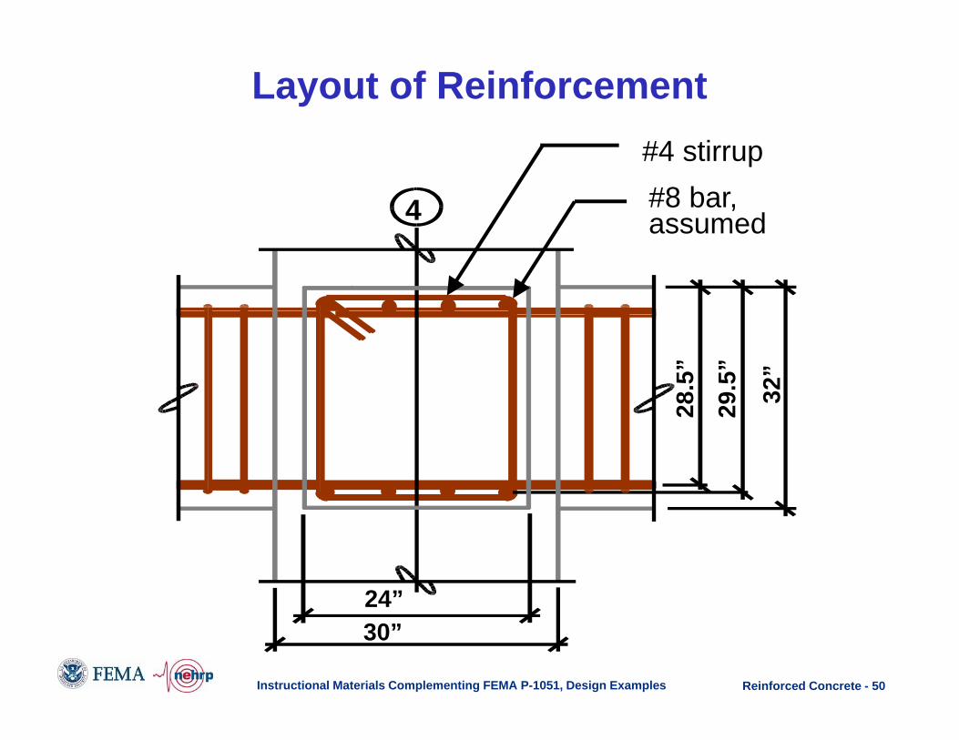
30”24”
32”
29.5
”28
.5”
4
#4 stirrup#8 bar, assumed
Layout of Reinforcement

Reinforced Concrete - 51Instructional Materials Complementing FEMA P-1051, Design Examples
Design Aspect Strength Used
Beam flexure Design strength
Beam shear Maximum probable strength
Beam-column joint Maximum probable strength
Column flexure 1.2 times nominalbeam strength
Column shear Maximum probable strength
Design Strengths

Reinforced Concrete - 52Instructional Materials Complementing FEMA P-1051, Design Examples
Bending Moment Envelopes:Frame 1 Beams, 7th Floor

Reinforced Concrete - 53Instructional Materials Complementing FEMA P-1051, Design Examples
Design for Negative Moment at the Face of the Interior Support (Grid A’):
Mu = 1.46(-602) + 0.5(-278) + 1.0(-3,973) = -4,976 inch-kips
One #7 bars in addition to the four #8 bars required for minimum steel:
As = 4(0.79) + 1(0.60) = 3.76 in^2a = 3.76 (60)/[0.85 (5) 24] = 2.21 inchesFMn = 0.9(3.76)60(29.5 – 2.21/2) = 5,765 inch-kips
> 4,976 inch-kips.
Beam Reinforcement: Longitudinal

Reinforced Concrete - 54Instructional Materials Complementing FEMA P-1051, Design Examples
Minimum of two bars continuous top and bottom:
OK (three #8 bars continuous top OK (four #8 bars continuous top and bottom)
Positive moment strength greater than 50 percent negative moment strength at a joint:
OK (at all joints)
Minimum strength along member greater than 0.25 maximum strength:
OK (As provided = four #8 bars is more than 25 percent of reinforcement provided at joints)
Check additional requirements:
Beam Reinforcement: Longitudinal (continued)

Reinforced Concrete - 55Instructional Materials Complementing FEMA P-1051, Design Examples
14
4
Beam Reinforcement: Layout

Reinforced Concrete - 56Instructional Materials Complementing FEMA P-1051, Design Examples
kips 4.1041.34210
841,6929,7,
21
gravun
prpre V
MMV
Probable moment strength, Mpr (k-in)
Vu,grav = 34.1 kips
B C
20’ – 30” = 17’-6”=210”
7,929
6,841
Assumed hingingmechanism
Determine Beam Design Shear

Reinforced Concrete - 57Instructional Materials Complementing FEMA P-1051, Design Examples
Design shear
Factoredgravity shear
Seismic shear
Beam moments
Hinge locations
(a)Seismic moment(tension side)in.-kips
(d)Design shearseismic + gravity
240"210"
15" 15"
(c)Gravity shear(1.42D + 0.5L)
(b)Seismic shear
A A' B C
Loading
7,042 7,042 7,042 7,042
5,5195,5195,5195,519
58.1
58.1
58.1
58.1
58.1
58.1
kipspositive
32.9
33.8
33.3
33.3
33.3
33.3
25.291.9
24.891.4
24.891.4
24.891.4
24.891.4
24.391.0 kips
positive
kipspositive
Beam Shear Force

Reinforced Concrete - 58Instructional Materials Complementing FEMA P-1051, Design Examples
At ends of beam s = 6 in.(near midspan, s = 6.0 in. w/ 2 legged stirrup)
in. 2.104.104
)5.29)(60)(8.0(75.0max
e
yv
VdfA
s
Vseismic > 50% Vu therefore take Vc = 0
Use 4 legged #4 stirrups
Beam Reinforcement: Transverse

Reinforced Concrete - 59Instructional Materials Complementing FEMA P-1051, Design Examples
• Check maximum spacing of hoops within plastic hinge length (2h)– d/4 = 7.4 in.– 6db = 6.0 in.– 6 in.
Therefore, 6.0 in. spacing at ends is adequate
At beam rebar splices, s = 4.0 in.
Beam Reinforcement: Transverse

Reinforced Concrete - 60Instructional Materials Complementing FEMA P-1051, Design Examples
But how to compute Vcol?
bottomsy
topsy
colj
AfC
AfT
VCTV
,
,
25.1
25.1
CTVcol
Vj
Joint Shear Force

Reinforced Concrete - 61Instructional Materials Complementing FEMA P-1051, Design Examples
h
Vcol
l c
V e,R
M pr,R
V e,L
M pr,L
Vcol
kips 2.108
1562
303.703.70841,6929,7
colV
At 7th Floor, Column C:
c
LRRprLpr
col l
hVVMMV
2,,
Joint Shear Force

Reinforced Concrete - 62Instructional Materials Complementing FEMA P-1051, Design Examples
kipskipsV
AfV
kipsVCTV
kipsAfC
kipsAfT
n
jcn
colj
botsy
topsy
41181195585.0
955)30(000,51515
411
23725.1
28225.1
2'
,
,
108
411
237282
Joint Shear Force

Reinforced Concrete - 63Instructional Materials Complementing FEMA P-1051, Design Examples
30"
Level 7
Level 6
20'-0"20'-0"
32"
32"
PL = 78 kips IncludesPD = 367 kips level 7
13'-0
"
A A' B
Design column using standard P-M interaction curve
nbnc MM 2.1then:
10' gc
u
AfP Column:
Frame 1 Column Design

Reinforced Concrete - 64Instructional Materials Complementing FEMA P-1051, Design Examples
Column moments (Level 7),assume uniform distributiontop and bottom
ft-k 285,14406,6498,52.1
nbnc MM 2.1
Beam moments (Level 7)
A A' B6,406
5,498
7,142
7,142
Column Design Moments
Design for strong column based on nominal beam moment strengths

Reinforced Concrete - 65Instructional Materials Complementing FEMA P-1051, Design Examples
nl: number of longitudinal bars that are laterally supported by the corner of hoops or by seismic hooks
Column Transverse Reinforcement

Reinforced Concrete - 66Instructional Materials Complementing FEMA P-1051, Design Examples
3h144s x
o
Column Transverse Reinforcement
Maximum spacing is smallest of:h/4 = 30/4 = 7.5 in.
6db = 6*1.0 = 6.0 in. (#8 bars)so calculated as follows:
for 12 #8 vertical bars and #4 hoops, hx = 8.33 in. and so = 5.72 in.
Next, check confinement requirements……

Reinforced Concrete - 67Instructional Materials Complementing FEMA P-1051, Design Examples
2
2
in81.0605)27)(4(09.0'09.0
and
in63.01729900
605)27)(4(3.01'3.0
yt
ccsh
ch
g
yt
ccsh
ffsbA
AA
ffsbA
Assume 4 in. hoop spacing:fc' < 10,000 psi and Pu< 0.3fc'Ag Equation (c) was not required.
Column Transverse Reinforcement
Therefore, use #4 bar hoops with 4 legsAsh = 0.80 in2

Reinforced Concrete - 68Instructional Materials Complementing FEMA P-1051, Design Examples
Mpr,2
Mpr,4
Mpr,1
Mpr,3
n
Mpr,top
Mpr,bottom
Vseismic
Vseismic
Determine Column Shear
Based on probable moment strength of columns and can be limited by probable moment strength of beams

Reinforced Concrete - 69Instructional Materials Complementing FEMA P-1051, Design Examples
Vc can be included in shear calculation
kips,22520
)3)(30(520'
For min gc AfP
kips241)124(
)940,14(2eV
Based on column moments:
Mpr,col = 14,940 k-in (12 #8 vert and Pmax)
Column Shear Design

Reinforced Concrete - 70Instructional Materials Complementing FEMA P-1051, Design Examples
4 legs #4s = 6 in. max
Hoops:
OK kips 241 kips 252)220117(75.0)(
kips2206
)5.27)(60(8.0
kips117)5.27)(30(000,52'2
scn
yvs
cc
VVVs
dfAV
bdfV
Column Shear Design
Assume 6 in. max hoop spacing at mid-height of column

Reinforced Concrete - 71Instructional Materials Complementing FEMA P-1051, Design Examples
Level 7
Level 6
30"
32"
32"
30"
30"
(12) #8 bars
#4 hoops
+ +
2"7
at 4
"2"
7 at
4"
7 at
6"
7 at
4"
2"
A'
• Confinement length,lo, greater of:• h = 30 in.• Hc/6 = (156-32)/6 =
20.7 in.• 18 in.
– Therefore, use 30 in.
Column Reinforcement

Reinforced Concrete - 72
Structural Wall Example
5 @ 20’ = 100’
7 @
30’
= 2
10’
A A’ B C C’ D1
2
3
4
5
6
7
8
N
Typical Floor Plan
Instructional Materials Complementing FEMA P-1051, Design Examples
• Same building as moment frame example
• 12-story concrete building
• N-S direction: SMF
• E-W direction: dual system
• Seismic Design Category D
• Modal Analysis Procedure
Shear wall @ grid 3-6

Reinforced Concrete - 73Instructional Materials Complementing FEMA P-1051, Design Examples
Shear wall cross section
Ag = (16)(210)+2(30)(30) = 5,160 sq in
Acv = 16[(210)+2(30)] = 4,320 sq in
16”
17’-6”=210”
30” x 30” column
Structural Wall

Reinforced Concrete - 74Instructional Materials Complementing FEMA P-1051, Design Examples
Vu = 769 kips (below level 2)
f’c = 5,000 psi, fy = 60 ksiα = 2.0 = 0.6 (per ACI 9.3.4(a))
Req’d t = 0.0019Min (and t) = 0.0025
Use #5 @ 12” o.c. each face:t= 0.0032 and Vn = 869 kips
Acv
l
t
Panel to Acv
ytccvn ffAV '
Shear Panel Reinforcement

Reinforced Concrete - 75Instructional Materials Complementing FEMA P-1051, Design Examples
At ground floor: shear and moment determined from the lateral analysis and axial load from gravity load run down.
All are factored forces.
• Mu = 30,641 kip-ft• Pu,max = 6,044 kips• Pu,min = 2,460 kips
Axial-Flexural Design

Reinforced Concrete - 76Instructional Materials Complementing FEMA P-1051, Design Examples
Axial and Flexural Design
P-M interactionWall reinforcement: #5 @12” o.c.
Boundary reinforcement: 12 #9 each end

Reinforced Concrete - 77Instructional Materials Complementing FEMA P-1051, Design Examples
Need confined boundary element
(extend up to below 9th floor where max stress < 0.15f’c)
'49.046.2284,444
)12(641,305,1606,044
cu
g
u fksiS
MAP
Use stress-based procedure (ACI 18.10.6.3).
Boundary Elements required if max stress > 0.2f’c
Ground level axial load and moment are determined based on factored forces.
Boundary Element Check

Reinforced Concrete - 78Instructional Materials Complementing FEMA P-1051, Design Examples
Length = larger of c/2 or c-0.1Lw
From P-M interaction, max c = 72.6 in.So, c/2 = 38.8 and c-0.1Lw = 50.6 in
Since length > column dimension, either• Extend boundary into wall panel• Increase f’c = reduce boundary element length
For this example, assume f’c = 7,000 psi, Then req’d boundary element length is 28.7 in.
Boundary Element Length

Reinforced Concrete - 79Instructional Materials Complementing FEMA P-1051, Design Examples
Width of the flexural compression zone, b > 12in. or hu/16
#5 with 4 legs, Ash = 1.24 in2
2'
in13.1607)27)(4(09.009.0
y
ccsh f
fsbA
Boundary Element Confinement
Transverse reinforcement in boundary elements is to bedesigned essentially like column transverse reinforcement.
Assume #5 ties and 4 in. spacing

Reinforced Concrete - 80Instructional Materials Complementing FEMA P-1051, Design Examples
Questions

Reinforced Concrete - 81Instructional Material Complementing FEMA P-1051, Design Examples
• NOTICE: Any opinions, findings, conclusions, or recommendations expressed in this publication do not necessarily reflect the views of the Federal Emergency Management Agency. Additionally, neither FEMA nor any of its employees make any warranty, expressed or implied, nor assume any legal liability or responsibility for the accuracy, completeness, or usefulness of any information, product or process included in this publication.
• The opinions expressed herein regarding the requirements of the NEHRP Recommended Seismic Provisions, the referenced standards, and the building codes are not to be used for design purposes. Rather the user should consult the jurisdiction’s building official who has the authority to render interpretation of the code.
• Any modifications made to the file represent the presenters' opinion only.
DISCLAIMER