rego globe & angle valves - gasequipment.com · 60 g l o b e & a n g l e v a l v es general...
TRANSCRIPT
57
Globe &
A
ngle ValvesRegO® Globe & Angle Valves
LP-Gas Hose-End Filling Valves (With ACME Connectors)Safety Warnings Purpose
In its continuing quest for safety, REGO® publishes a series of bulletins explaining the hazards associated withthe use, misuse, and aging of LP-Gas valves and regulators. It is hoped that these factual bulletins will makeclear to LP-Gas dealer managers and service personnel, that the utmost care and attention must be used in theinstallation, inspection, and maintenance of these products, or problems could occur which would result ininjuries and property damage.
The National Fire Protection Association Pamphlet #58 - 2004 Edition, “Liquified Petroleum Gas Code” statesthat, “persons who transfer liquid LP-Gas, who are employed to transport LP-Gas, or whose primary duties fallwithin the scope of this code shall be trained in proper handling procedures. Refresher training shall be provid-ed at least every three years. The training shall be documented.” These “REGO® Safety Warnings” may be use-ful in training new employees and reminding older employees of hazards that can occur. It is recommended thatall employees be furnished with a copy of NPGA Safety Pamphlet 306-88, “LP-Gas Regulator and ValveInspection and Maintenance.”
Nature of WarningsIt is recognized that warnings should be as brief as possible, but fac-tors involved in filler valve and filling valves failure are not simple.They need to be fully understood so that proper procedures and main-tenance can be used to prevent accidents. If there is a simple warning,it would be:
This bulletin is not intended to be an exhaustive treatment of the sub-ject of filler valves and certainly does not cover all safety practices thatshould be followed in the installation, operation and maintenance ofLPGas systems, which include filler and filling valves.
Hose-End Filling Valves With ACME Connectors
They could open accidentally or they could be damaged. Dragging willcause abnormal wear and eventual valve failure. Foreign material willlodge in the connector which can cause failure of the filler valve.
Hose-end valves must never be dragged over the ground ordropped or banged into the truck when the hose is reeled in.
To prevent hazardous conditions, operators should follow this proce-dure on every filling application:
� Always wear gloves and eye protection.
� Check for foreign material in hose-end valve and the filler valve,and if present, remove with extreme care. If material cannot besafely removed, do not proceed with filling and replace valve.
� Make sure the ACME connector spins on easily by hand.� If leak is noticed when filling is started, stop the operation and cor-rect the leaking condition.
� After filling, bleed the gas trapped between the filler valve and hose-end valve by using the vent on the hose-end valve or by slightly loosening coupling nut to vent the gas before disconnecting.
If gas does not stop venting, then filler valve or hose-endvalve is leaking. Do not disconnect filling connector. This is ahazardous situation and your company procedure for handlingthis problem must be carefully followed.
Loosen filling valve from filler valve very slowly. If there is a leak, know procedure to follow.
Make sure your company has such a procedure. Inspection ofFilling Valves with Handwheel� Valves should be inspected at least once a month to be sure thevalve handle is tight and not damaged, that the stem is not bent andthat there is no “play” in the threads in the bonnet. “Play” will normallynot be noticed if the valve is under pressure.
� The ACME threads should be examined for wear, dents or nicks andthe seating area should be clean and smooth.
Inspection of Quick Acting Filling Valves� Valves should be inspected daily to make sure locking mechanism func-tions properly.
� The ACME threads should be examined for wear, dents or nicks and theseating area should be clean and smooth.
� The retaining ring on the filler connection should be examined to makesure it is properly holding the female ACME rotating nut or handle so asto keep the surface that seats on the filler valve gasket protected.
� If any problems are evident, valves should be immediately replaced orrepaired.
Larger Filler and Filling ValvesFor 2¼” and 3¼” valves with ACME connections, use only the specialwrenches designed for the purpose.
Do not use pipe wrenches or hammers to tighten the connections. All ofthe previous warnings about the smaller valves also apply here.
General WarningAll REGO® products are mechanical devices that will eventually becomeinoperative due to wear, contaminants, corrosion and aging componentsmade of materials such as rubber and metal. The environment and con-ditions of use will determine the safe service life of these products.Periodic inspection and maintenance are essential. Because REGO®products have a long and proven record of quality and service, LP-Gasdealers may forget the hazards that can occur because a filler valve or afilling valve is used beyond its safe service life. Life of these valves isdetermined by the environment in which they “live.” The LP-Gas dealerknows better than anyone what this environment is. Note: There is adeveloping trend in state legislation and in proposed national legislationto make the owner of products responsible for replacing products beforethey reach the end of their safe useful life. LP-Gas dealers should beaware of the legislation which could affect them.
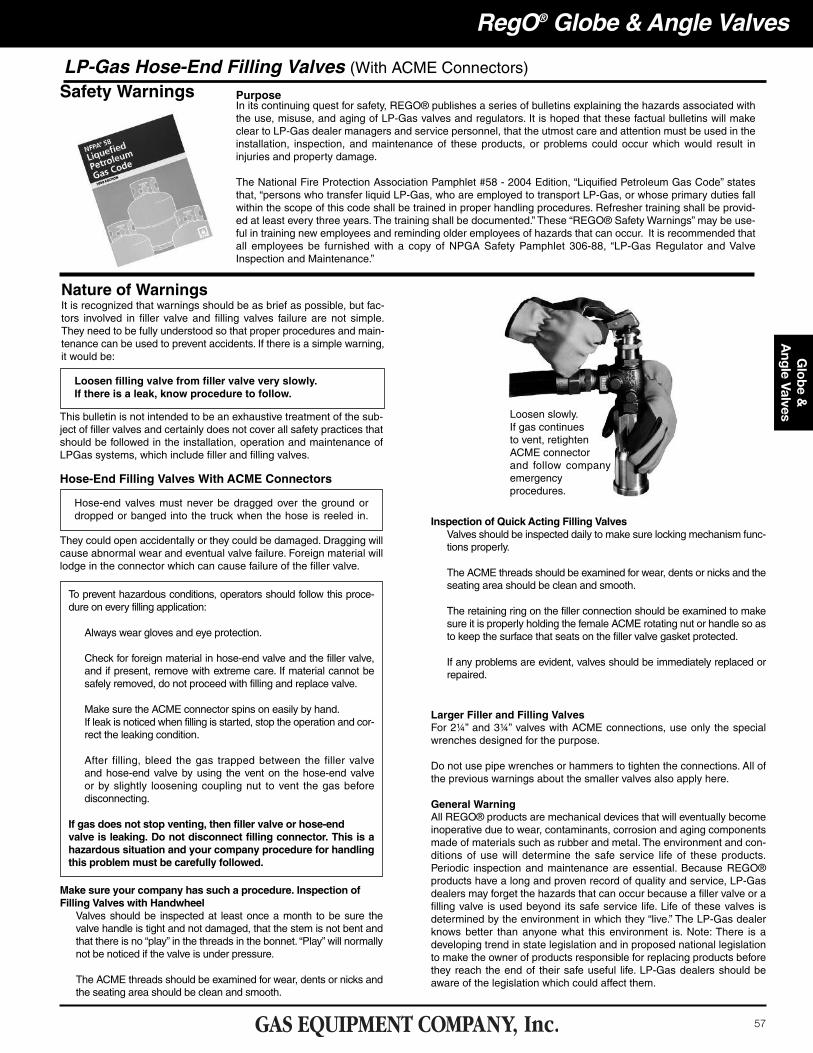
Loosen slowly.If gas continuesto vent, retightenACME connectorand follow companyemergencyprocedures.
58
Glo
be &
A
ngle
Val
ves
RegO® Globe & Angle Valves
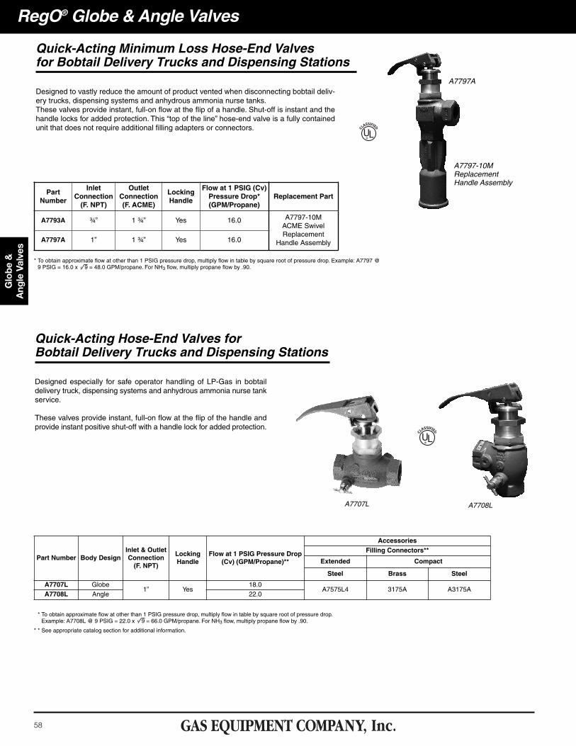
Quick-Acting Minimum Loss Hose-End Valvesfor Bobtail Delivery Trucks and Dispensing Stations
Designed to vastly reduce the amount of product vented when disconnecting bobtail deliv-ery trucks, dispensing systems and anhydrous ammonia nurse tanks. These valves provide instant, full-on flow at the flip of a handle. Shut-off is instant and thehandle locks for added protection. This “top of the line” hose-end valve is a fully containedunit that does not require additional filling adapters or connectors. UL®
Quick-Acting Hose-End Valves forBobtail Delivery Trucks and Dispensing Stations
Designed especially for safe operator handling of LP-Gas in bobtaildelivery truck, dispensing systems and anhydrous ammonia nurse tankservice.
These valves provide instant, full-on flow at the flip of the handle andprovide instant positive shut-off with a handle lock for added protection.
A7707L A7708L
UL®
A7797A
* To obtain approximate flow at other than 1 PSIG pressure drop, multiply flow in table by square root of pressure drop. Example: A7797 @9 PSIG = 16.0 x 9 = 48.0 GPM/propane. For NH3 flow, multiply propane flow by .90.
PartNumber
InletConnection(F. NPT)
OutletConnection(F. ACME)
LockingHandle
Flow at 1 PSIG (Cv)Pressure Drop*(GPM/Propane)
Replacement Part
A7793A ¾” 1 ¾” Yes 16.0 A7797-10MACME SwivelReplacement
Handle AssemblyA7797A 1” 1 ¾” Yes 16.0
* To obtain approximate flow at other than 1 PSIG pressure drop, multiply flow in table by square root of pressure drop. Example: A7708L @ 9 PSIG = 22.0 x 9 = 66.0 GPM/propane. For NH3 flow, multiply propane flow by .90.
* * See appropriate catalog section for additional information.
Part Number Body DesignInlet & OutletConnection(F. NPT)
LockingHandle
Flow at 1 PSIG Pressure Drop(Cv) (GPM/Propane)**
AccessoriesFilling Connectors**
Extended Compact
Steel Brass Steel
A7707L Globe1” Yes
18.0A7575L4 3175A A3175A
A7708L Angle 22.0
A7797-10MReplacementHandle Assembly
59
Globe &
A
ngle ValvesRegO® Globe & Angle Valves
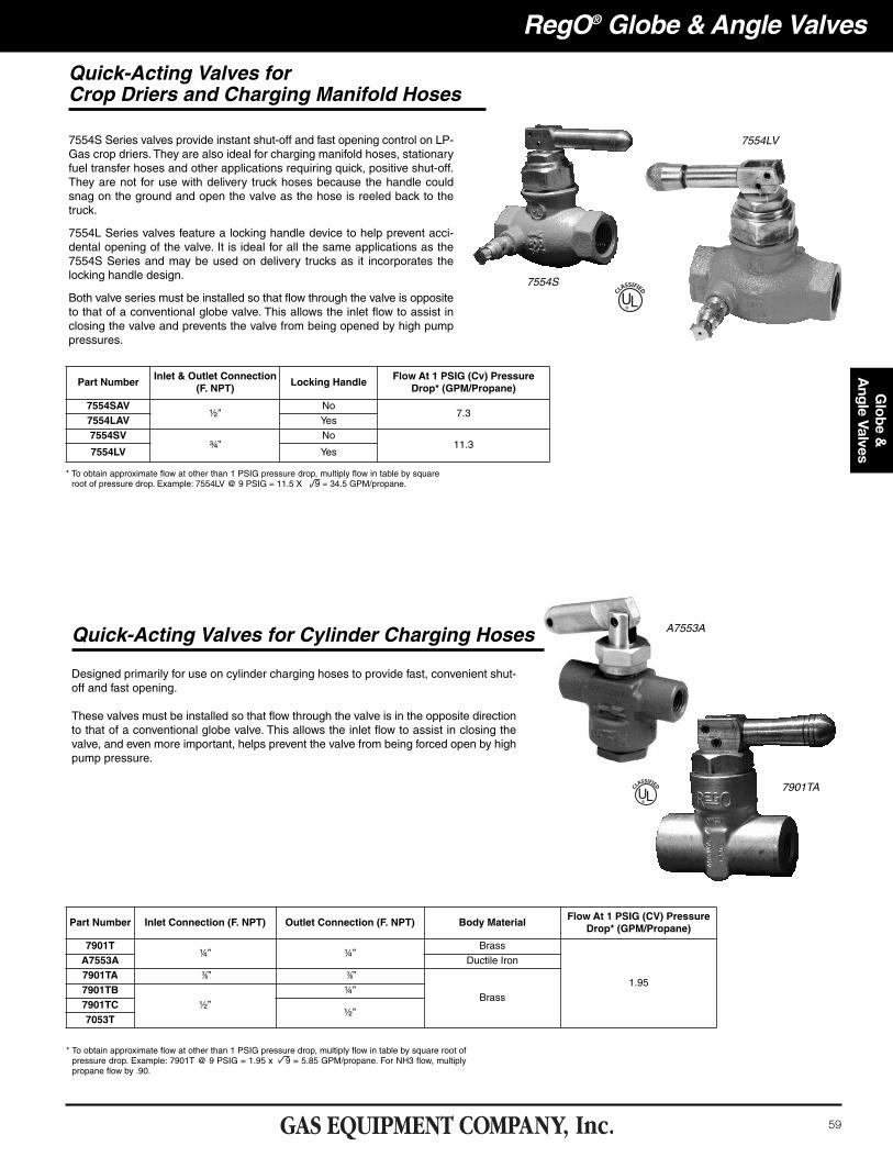
Quick-Acting Valves forCrop Driers and Charging Manifold Hoses
7554S Series valves provide instant shut-off and fast opening control on LP-Gas crop driers. They are also ideal for charging manifold hoses, stationaryfuel transfer hoses and other applications requiring quick, positive shut-off.They are not for use with delivery truck hoses because the handle couldsnag on the ground and open the valve as the hose is reeled back to thetruck.
7554L Series valves feature a locking handle device to help prevent acci-dental opening of the valve. It is ideal for all the same applications as the7554S Series and may be used on delivery trucks as it incorporates thelocking handle design.
Both valve series must be installed so that flow through the valve is oppositeto that of a conventional globe valve. This allows the inlet flow to assist inclosing the valve and prevents the valve from being opened by high pumppressures.
7554S
UL®
7554LV
Designed primarily for use on cylinder charging hoses to provide fast, convenient shut-off and fast opening.
These valves must be installed so that flow through the valve is in the opposite directionto that of a conventional globe valve. This allows the inlet flow to assist in closing thevalve, and even more important, helps prevent the valve from being forced open by highpump pressure.
Quick-Acting Valves for Cylinder Charging Hoses
UL®
A7553A
7901TA
* To obtain approximate flow at other than 1 PSIG pressure drop, multiply flow in table by squareroot of pressure drop. Example: 7554LV @ 9 PSIG = 11.5 X 9 = 34.5 GPM/propane.
Part NumberInlet & Outlet Connection
(F. NPT)Locking Handle
Flow At 1 PSIG (Cv) PressureDrop* (GPM/Propane)
7554SAV½”
No7.3
7554LAV Yes
7554SV¾”
No11.3
7554LV Yes
* To obtain approximate flow at other than 1 PSIG pressure drop, multiply flow in table by square root ofpressure drop. Example: 7901T @ 9 PSIG = 1.95 x 9 = 5.85 GPM/propane. For NH3 flow, multiplypropane flow by .90.
Part Number Inlet Connection (F. NPT) Outlet Connection (F. NPT) Body MaterialFlow At 1 PSIG (CV) Pressure
Drop* (GPM/Propane)
7901T¼” ¼”
Brass
1.95
A7553A Ductile Iron
7901TA �3⁄8” �3⁄8”
Brass7901TB
½”
¼”
7901TC½”
7053T
60
Glo
be &
A
ngle
Val
ves
General InformationRegO® Globe and Angle Valves are designed and manufactured espe-cially to meet the rigid requirements of the LP-Gas industry. The highquality construction and wide variety of sizes and styles also makethem highly suited to many other industries such as anhydrous ammo-nia, chemical and petrochemical.
These ductile iron valves are available in both threaded and flangedconnections. Threaded connections are available in ½” F. NPT to 3” F.NPT sizes. Flanged connections are available in 1½”, 2” and 3” pipesizes.
The ductile iron used in these valves has a 60,000 PSIG tensilestrength which closely approaches that of steel castings. Its yieldstrength of 45,000 PSIG and elongation of 15% is also comparable tothat of steel castings. These material features assure the ability of thevalve body to withstand impact, wrenching stresses and thermal shock.This ductile iron conforms to ASTM specification A395.
RegO® globe and angle valves are designed for working pressures up to400 PSIG WOG and for operating temperatures from -40° F. to +160° F.
Wrenches must never be used to operate valves equipped withhandwheels and designed for hand operation.
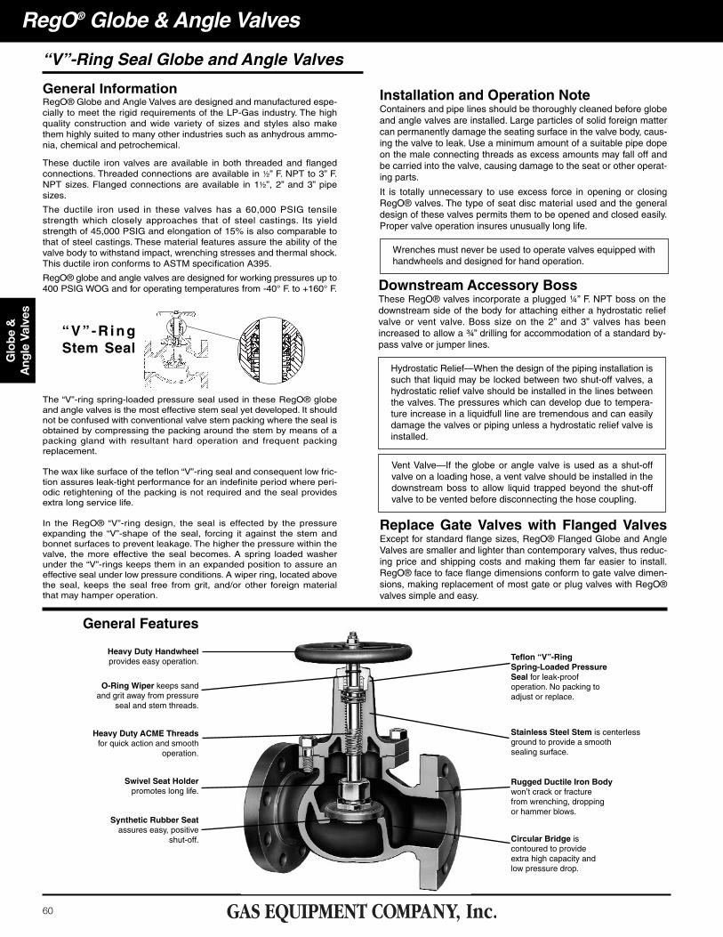
“V” -R ing Stem Seal
The “V”-ring spring-loaded pressure seal used in these RegO® globeand angle valves is the most effective stem seal yet developed. It shouldnot be confused with conventional valve stem packing where the seal isobtained by compressing the packing around the stem by means of apacking gland with resultant hard operation and frequent packingreplacement.
The wax like surface of the teflon “V”-ring seal and consequent low fric-tion assures leak-tight performance for an indefinite period where peri-odic retightening of the packing is not required and the seal providesextra long service life.
In the RegO® “V”-ring design, the seal is effected by the pressureexpanding the “V”-shape of the seal, forcing it against the stem andbonnet surfaces to prevent leakage. The higher the pressure within thevalve, the more effective the seal becomes. A spring loaded washerunder the “V”-rings keeps them in an expanded position to assure aneffective seal under low pressure conditions. A wiper ring, located abovethe seal, keeps the seal free from grit, and/or other foreign materialthat may hamper operation.
Installation and Operation NoteContainers and pipe lines should be thoroughly cleaned before globeand angle valves are installed. Large particles of solid foreign mattercan permanently damage the seating surface in the valve body, caus-ing the valve to leak. Use a minimum amount of a suitable pipe dopeon the male connecting threads as excess amounts may fall off andbe carried into the valve, causing damage to the seat or other operat-ing parts.
It is totally unnecessary to use excess force in opening or closingRegO® valves. The type of seat disc material used and the generaldesign of these valves permits them to be opened and closed easily.Proper valve operation insures unusually long life.
Downstream Accessory BossThese RegO® valves incorporate a plugged ¼” F. NPT boss on thedownstream side of the body for attaching either a hydrostatic reliefvalve or vent valve. Boss size on the 2” and 3” valves has beenincreased to allow a ¾” drilling for accommodation of a standard by-pass valve or jumper lines.
Hydrostatic Relief—When the design of the piping installation issuch that liquid may be locked between two shut-off valves, ahydrostatic relief valve should be installed in the lines betweenthe valves. The pressures which can develop due to tempera-ture increase in a liquidfull line are tremendous and can easilydamage the valves or piping unless a hydrostatic relief valve isinstalled.
Vent Valve—If the globe or angle valve is used as a shut-offvalve on a loading hose, a vent valve should be installed in thedownstream boss to allow liquid trapped beyond the shut-offvalve to be vented before disconnecting the hose coupling.
Replace Gate Valves with Flanged ValvesExcept for standard flange sizes, RegO® Flanged Globe and AngleValves are smaller and lighter than contemporary valves, thus reduc-ing price and shipping costs and making them far easier to install.RegO® face to face flange dimensions conform to gate valve dimen-sions, making replacement of most gate or plug valves with RegO®valves simple and easy.
General Features
Heavy Duty Handwheelprovides easy operation.
O-Ring Wiper keeps sandand grit away from pressure
seal and stem threads.
Heavy Duty ACME Threadsfor quick action and smooth
operation.
Swivel Seat Holderpromotes long life.
Synthetic Rubber Seatassures easy, positive
shut-off.
Teflon “V”-RingSpring-Loaded PressureSeal for leak-proof operation. No packing to adjust or replace.
Stainless Steel Stem is centerless ground to provide a smoothsealing surface.
Rugged Ductile Iron Bodywon’t crack or fracturefrom wrenching, droppingor hammer blows.
Circular Bridge iscontoured to provideextra high capacity andlow pressure drop.
RegO® Globe & Angle Valves
“V”-Ring Seal Globe and Angle Valves
61
Globe &
A
ngle ValvesRegO® Globe & Angle Valves
A7518FP
A7517FP
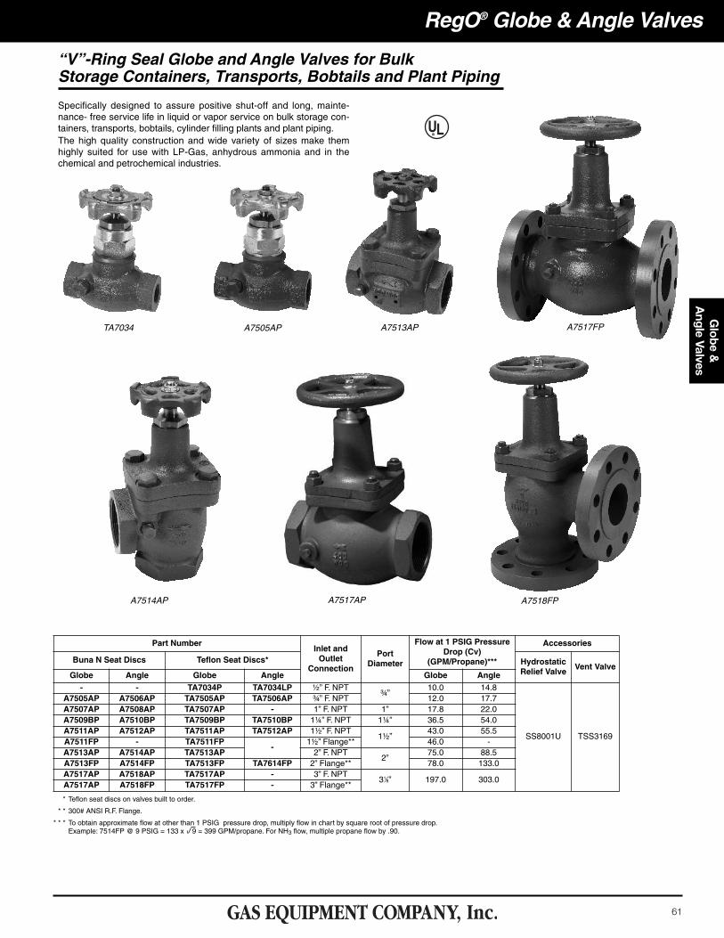
“V”-Ring Seal Globe and Angle Valves for BulkStorage Containers, Transports, Bobtails and Plant Piping
Specifically designed to assure positive shut-off and long, mainte-nance- free service life in liquid or vapor service on bulk storage con-tainers, transports, bobtails, cylinder filling plants and plant piping.The high quality construction and wide variety of sizes make themhighly suited for use with LP-Gas, anhydrous ammonia and in thechemical and petrochemical industries.
TA7034 A7505AP
A7514AP
A7513AP
A7517AP
* Teflon seat discs on valves built to order.
* * 300# ANSI R.F. Flange.
* * * To obtain approximate flow at other than 1 PSIG pressure drop, multiply flow in chart by square root of pressure drop.Example: 7514FP @ 9 PSIG = 133 x 9 = 399 GPM/propane. For NH3 flow, multiple propane flow by .90.
Part NumberInlet andOutlet
Connection
PortDiameter
Flow at 1 PSIG PressureDrop (Cv)
(GPM/Propane)***
Accessories
Buna N Seat Discs Teflon Seat Discs* HydrostaticRelief Valve
Vent ValveGlobe Angle Globe Angle Globe Angle- - TA7034P TA7034LP ½” F. NPT
¾”10.0 14.8
SS8001U TSS3169
A7505AP A7506AP TA7505AP TA7506AP ¾” F. NPT 12.0 17.7A7507AP A7508AP TA7507AP - 1” F. NPT 1” 17.8 22.0A7509BP A7510BP TA7509BP TA7510BP 1¼” F. NPT 1¼” 36.5 54.0A7511AP A7512AP TA7511AP TA7512AP 1½” F. NPT
1½”43.0 55.5
A7511FP - TA7511FP-
1½” Flange** 46.0 -A7513AP A7514AP TA7513AP 2” F. NPT
2”75.0 88.5
A7513FP A7514FP TA7513FP TA7614FP 2” Flange** 78.0 133.0A7517AP A7518AP TA7517AP - 3” F. NPT
31⁄8” 197.0 303.0A7517AP A7518FP TA7517FP - 3” Flange**
62
Glo
be &
A
ngle
Val
ves
RegO® Globe & Angle Valves
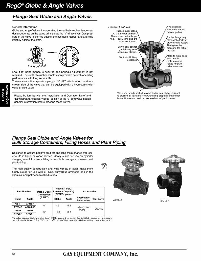
General InformationGlobe and Angle Valves, incorporating the synthetic rubber flange sealdesign, operate on the same principle as the “V”-ring valves. Gas pres-sure in the valve is exerted against the synthetic rubber flange, forcingit tightly against the stem.
Leak-tight performance is assured and periodic adjustment is notrequired. The synthetic rubber construction provides smooth operatingperformance with long service life.These valves all incorporate a plugged ¼” NPT side boss on the down-stream side of the valve that can be equipped with a hydrostatic reliefvalve or vent valve.
Flange Seal Globe and Angle Valves forBulk Storage Containers, Filling Hoses and Plant Piping
Designed to assure positive shut-off and long maintenance-free ser-vice life in liquid or vapor service. Ideally suited for use on cylindercharging manifolds, truck filling hoses, bulk storage containers andplant piping.
The high quality construction and wide variety of sizes make themhighly suited for use with LP-Gas, anhydrous ammonia and in thechemical and petrochemical industries.
Flange Seal Globe and Angle Valves
General FeaturesRugged quick-acting
ACME threads on stem.Threads are under flangering . . . dust, sand and grit
can’t reach them.
Swivel seat cannotgrind during valveopening or closing.
Synthetic RubberSeat Disc
Nylon bearingsurrounds stem toprevent galling.
Rubber flange ringstem seal effectivelyprevents gas escape.The higher thepressure, the tighterthe seal.
Metal to metal backseat permitsreplacement offlange ring withvalve in service.
Please be familiar with the “Installation and Operation Note” and“Downstream Accessory Boss” section of the “V”-ring valve designgeneral information before ordering these valves.
Valve body made of shell molded ductile iron. Highly resistantto cracking or fracturing from wrenching, dropping or hammerblows. Bonnet and seal cap are steel on “A” prefix valves.
A7706 PA7704P
UL®
* To obtain approximate flow at other than 1 PSIG pressure drop, multiply flow in table by square root of pressuredrop. Example: A7704LP @ 9 PSIG =12.3 x 9 = 36.9 GPM/propane. For NH3 flow, multiply propane flow by .90.
Part Number Inlet & OutletConnection(F. NPT)
Flow at 1 PSIGPressure Drop (Cv)(GPM/Propane)*
Accessories
Globe Angle Globe AngleHydrostaticRelief Valve
Vent Valve
7704P 7704LP½” 7.3 12.3
SS8001J orSS8001L
TSS3169A7704P A7704LP7705P 7706P
¾” 11.5 17.7A7705P A7706P
63
Globe &
A
ngle ValvesRegO® Globe & Angle Valves
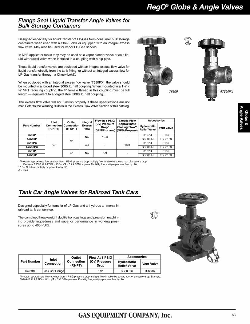
Flange Seal Liquid Transfer Angle Valves forBulk Storage Containers
Designed especially for liquid transfer of LP-Gas from consumer bulk storagecontainers when used with a Chek-Lok® or equipped with an integral excessflow valve. May also be used for vapor LP-Gas service.
In NH3 applicator tanks they may be used as a vapor bleeder valve or as a liq-uid withdrawal valve when installed in a coupling with a dip pipe.
These liquid transfer valves are equipped with an integral excess flow valve forliquid transfer directly from the tank fitting, or without an integral excess flow forLP-Gas transfer through a Check-Lok®.
When equipped with an integral excess flow valve (7550PX), the valve shouldbe mounted in a forged steel 3000 lb. half coupling. When mounted in a 1¼” x¾” NPT reducing coupling, the ¾” female thread in this coupling must be fulllength — equivalent to a forged steel 3000 lb. half coupling.
The excess flow valve will not function properly if these specifications are notmet. Refer to the Warning Bulletin in the Excess Flow Valve Section of this catalog.
UL®
7550P A7550PX
* To obtain approximate flow at other than 1 PSIG pressure drop, multiply flow in table by square root of pressure drop.Example: 7550P @ 9 PSIG = 13.3 x 9 = 39.9 GPM/propane. For NH3 flow, multiple propane flow by .90.
* * For NH3 flow, multiply propane flow by .90.A = Steel
Part NumberInlet
Connection(F. NPT)
OutletConnection(F. NPT)
IntegralExcessFlow
Flow at 1 PSIG(Cv) Pressure
Drop* (GPM/Propane)
Excess FlowApproximateClosing Flow**(GPM/Propane)
Accessories
HydrostaticRelief Valve
Vent Valve
7550P
¾”
¾”
No 13.3 -3127U 3165
A7550P SS8001J TSS3169
7550PXYes - 16.0
3127U 3165
A7550PX SS8001J TSS3169
7551P½” No 8.9 -
3127U 3165
A7551P SS8001J TSS3169
Tank Car Angle Valves for Railroad Tank Cars
Designed especially for transfer of LP-Gas and anhydrous ammonia inrailroad tank car service.
The combined heavyweight ductile iron castings and precision machin-ing provide ruggedness and superior performance in working pres-sures up to 400 PSIG.
UL®
* To obtain approximate flow at other than 1 PSIG pressure drop, multiply flow in table by square root of pressure drop. Example:TA7894P @ 9 PSIG = 112 x 9 = 336 GPM/propane. For NH3 flow, multiply propane flow by .90.
Part NumberInlet
Connection
OutletConnection(F.NPT)
Flow At 1 PSIG(Cv) Pressure
Drop
Accessories
HydrostaticRelief Valve
Vent Valve
TA7894P Tank Car Flange 2” 112 SS8001U TSS3169
64
Glo
be &
A
ngle
Val
ves
RegO® Globe & Angle Valves
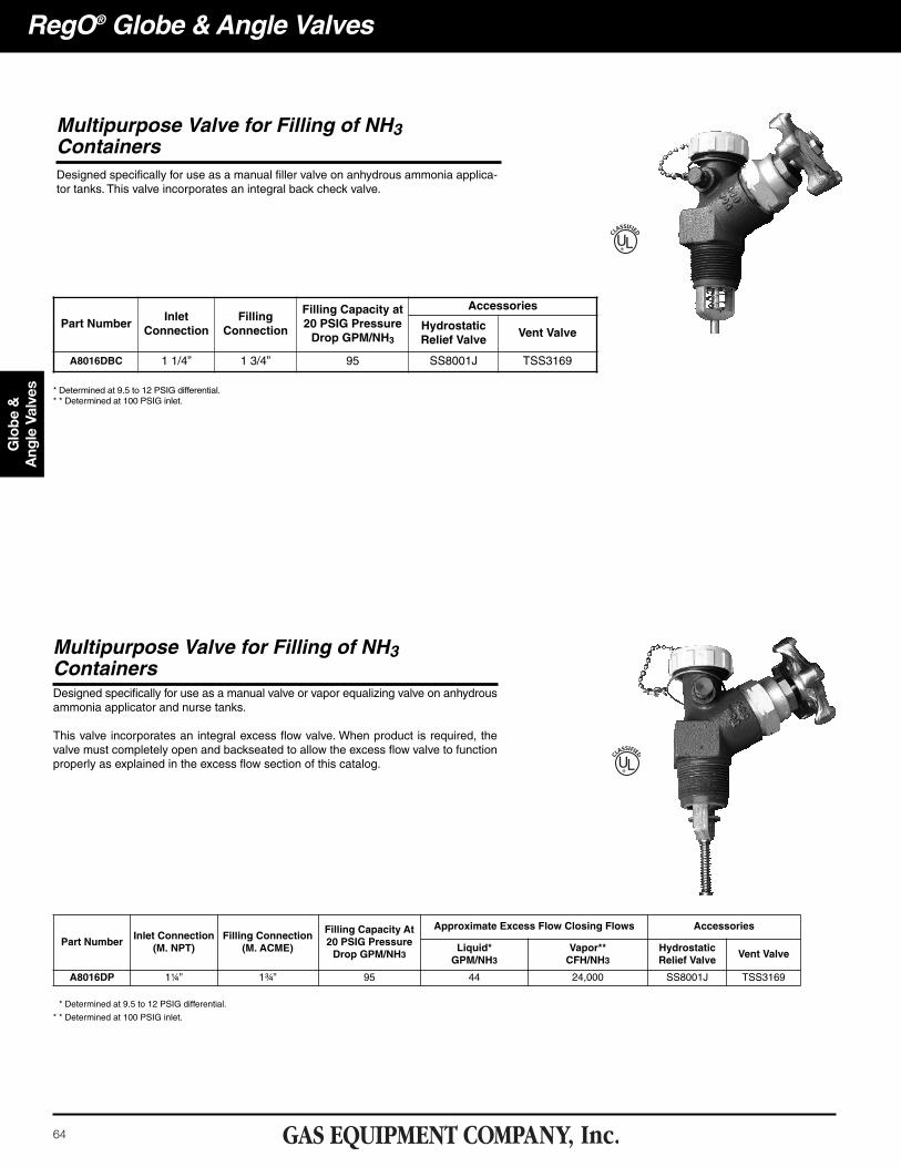
Multipurpose Valve for Filling of NH3ContainersDesigned specifically for use as a manual filler valve on anhydrous ammonia applica-tor tanks. This valve incorporates an integral back check valve.
UL®
Multipurpose Valve for Filling of NH3ContainersDesigned specifically for use as a manual valve or vapor equalizing valve on anhydrousammonia applicator and nurse tanks.
This valve incorporates an integral excess flow valve. When product is required, thevalve must completely open and backseated to allow the excess flow valve to functionproperly as explained in the excess flow section of this catalog. UL®
Part NumberInlet
ConnectionFilling
Connection
Filling Capacity at20 PSIG PressureDrop GPM/NH3
Accessories
HydrostaticRelief Valve
Vent Valve
A8016DBC 1 1/4” 1 3/4” 95 SS8001J TSS3169
* Determined at 9.5 to 12 PSIG differential.* * Determined at 100 PSIG inlet.
* Determined at 9.5 to 12 PSIG differential.
* * Determined at 100 PSIG inlet.
Part NumberInlet Connection
(M. NPT)Filling Connection
(M. ACME)
Filling Capacity At20 PSIG PressureDrop GPM/NH3
Approximate Excess Flow Closing Flows Accessories
Liquid*GPM/NH3
Vapor**CFH/NH3
HydrostaticRelief Valve
Vent Valve
A8016DP 1¼” 1¾” 95 44 24,000 SS8001J TSS3169
65
Globe &
A
ngle ValvesRegO® Globe & Angle Valves
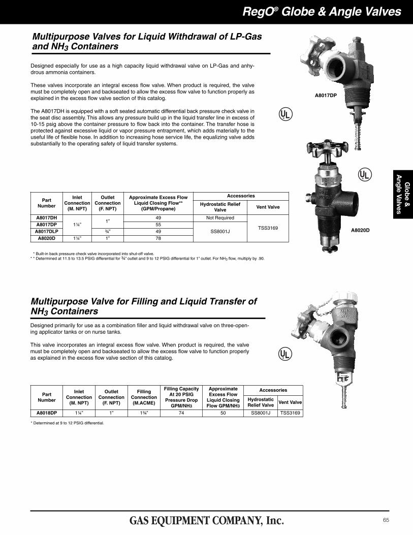
Multipurpose Valves for Liquid Withdrawal of LP-Gas and NH3 Containers
Designed especially for use as a high capacity liquid withdrawal valve on LP-Gas and anhy-drous ammonia containers.
These valves incorporate an integral excess flow valve. When product is required, the valvemust be completely open and backseated to allow the excess flow valve to function properly asexplained in the excess flow valve section of this catalog.
The A8017DH is equipped with a soft seated automatic differential back pressure check valve inthe seat disc assembly. This allows any pressure build up in the liquid transfer line in excess of10-15 psig above the container pressure to flow back into the container. The transfer hose isprotected against excessive liquid or vapor pressure entrapment, which adds materially to theuseful life of flexible hose. In addition to increasing hose service life, the equalizing valve addssubstantially to the operating safety of liquid transfer systems.
Designed primarily for use as a combination filler and liquid withdrawal valve on three-open-ing applicator tanks or on nurse tanks.
This valve incorporates an integral excess flow valve. When product is required, the valvemust be completely open and backseated to allow the excess flow valve to function properlyas explained in the excess flow valve section of this catalog.
Multipurpose Valve for Filling and Liquid Transfer of NH3 Containers
* Built-in back pressure check valve incorporated into shut-off valve.* * Determined at 11.5 to 13.5 PSIG differential for ¾” outlet and 9 to 12 PSIG differential for 1” outlet. For NH3 flow, multiply by .90.
Part Number
InletConnection(M. NPT)
OutletConnection(F. NPT)
Approximate Excess FlowLiquid Closing Flow**(GPM/Propane)
Accessories
Hydrostatic ReliefValve
Vent Valve
A8017DH1¼”
1”49 Not Required
TSS3169A8017DP 55
SS8001JA8017DLP ¾” 49
A8020D 1¼” 1” 78
A8017DP
A8020D
* Determined at 9 to 12 PSIG differential.
Part Number
InletConnection(M. NPT)
OutletConnection(F. NPT)
FillingConnection(M.ACME)
Filling CapacityAt 20 PSIG
Pressure Drop GPM/NH3
Approximate Excess Flow Liquid Closing Flow GPM/NH3
Accessories
HydrostaticRelief Valve
Vent Valve
A8018DP 1¼” 1” 1¾” 74 50 SS8001J TSS3169
66
Glo
be &
A
ngle
Val
ves
RegO® Globe & Angle Valves
The following warning information, Part Number 903-500, is includedwith each shipment of Quick-Acting and Tank Car Valves to the firstpurchaser of the product from the factory.
This information is intended to be forwarded throughout the productdistribution chain. Additional copies are available from REGO® andAuthorized Product Distributors.
Warning Notice