reformer - merrithew™ · 2 reformer owner’s manual user guidelines pilates equipment when used...
TRANSCRIPT
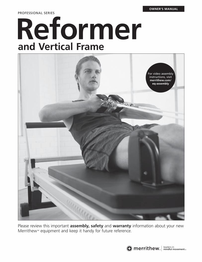
Please review this important assembly, safety and warranty information about your new Merrithew™ equipment and keep it handy for future reference.
OWNER’S MANUAL
Reformer and Vertical Frame
For video assembly instructions, visit merrithew.com/
eq-assembly
PROFESSIONAL SERIES
Reformer Owner’s Manual2
User GuidelinesPilates equipment when used effectively can faciliate many Pilates exercises safely and effectively. However, care and caution must be taken as there are some inherent dangers when using any exercise equipment — especially when spring resistance is involved.
For inexperienced or first-time users, this equipment should only be used under the supervision of a trained professional.
Please ensure that you and your clients/patients have received proper instruction regarding the correct and safe use of this equipment.
This manual includes general guidelines for setup and usage. To get the most out of this equipment, Merrithew offers instructional DVDs and manuals. Personalized training is offered through our Host, Licensed and Corporate Training Centers. Visit merrithew.com for more information.
REFORMER OWNER’S MANUAL
IMPORTANT!This manual contains important assembly, safety and warranty information. Read the manual carefully before using your new equipment and keep the manual on hand for future reference.
UNSAFE OR IMPROPER USE OF THIS EQUIPMENT BY FAILING TO READ AND COMPLY WITH ALL REQUIREMENTS AND WARNINGS COULD RESULT IN SERIOUS INJURY.
It is impossible to predict every situation and condition that can occur while using this equipment. Merrithew™ makes no representation about the safe use of any exercise equipment that cannot be predicted or avoided.
PLEASE DO NOT ATTEMPT TO ASSEMBLE ON YOUR OWN. SOME OF THESE STEPS REQUIRE TWO PEOPLE. PLEASE READ THESE INSTRUCTIONS COMPLETELY BEFORE BEGINNING ASSEMBLY.
Merrithew recommends cautious assembly and usage and wishes you many hours of safe and effective exercise.
CAUTION IMPROPER USE OF EXERCISE EQUIPMENT MAY CAUSE SERIOUS BODILY INJURY. TO REDUCE RISK, PLEASE READ THE FOLLOWING:
w Before starting any exercise program, consult a physician. Stop exercising immediately if you experience chest pain, feel faint, have difficulty breathing or experience discomfort.
w Before using equipment, read and follow the safety instructions in this manual and obtain thorough instruction from a qualified trainer. Use equipment for intended exercises only.
w NEVER stand with both feet on the wooden standing platform of an SPX Max Reformer. Step onto secured carriage first before placing one foot onto wooden standing platform. Always keep one foot on secured carriage.
w Do not use if equipment appears worn, broken or damaged. Do not attempt to repair equipment yourself without contacting Merrithew.
w When springs are used on the vertical frame, ensure spring clips are fully closed at both ends of springs. A spring clip that is only half closed risks coming undone and detaching with high force.
w When using the push-thru bar with springs attached from below, a trained professional must keep a hand on the bar at all times, and the safety chain must be attached. See Safety & Usage on page 21.
w Keep body, clothing and hair free from all moving parts.
w Ensure the equipment is properly adjusted for your size and ability level.
w For optimal performance, allow at least two feet of clear space on either side of a Merrithew Reformer. Before moving a Reformer, ensure ropes do not drag, springs are attached and carriage is secure.
w The SPX Max, V2 Max and Rehab V2 Max Reformers should be used by only one person at a time, not weighing over 350 lbs / 159 kgs.
w Do not allow children to use or be around equipment without adult supervision.
w Before using this Reformer, ensure that the carriage stopper is fully inserted and at least one spring is securely attached to the gearbar.
WARNING: As with any athletic activity, the use of exercise equipment involves risk of injury, damage and/or death.
By choosing to use Merrithew equipment, you and/or your clients/patients assume responsibility for that risk, not the people who sell, distribute and/or manufacture this equipment.
3
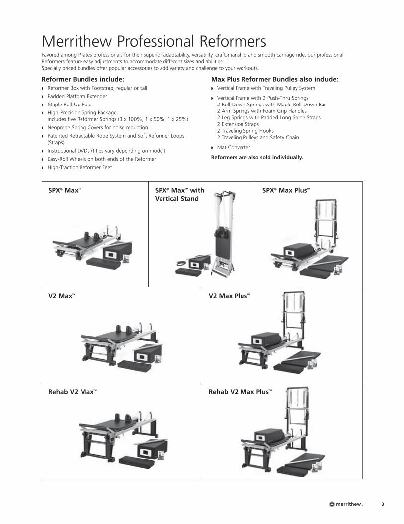
Merrithew Professional ReformersFavored among Pilates professionals for their superior adaptability, versatility, craftsmanship and smooth carriage ride, our professional Reformers feature easy adjustments to accommodate different sizes and abilities. Specially priced bundles offer popular accessories to add variety and challenge to your workouts.
Reformer Bundles include: w Reformer Box with Footstrap, regular or tall
w Padded Platform Extender
w Maple Roll-Up Pole
w High-Precision Spring Package, includes five Reformer Springs (3 x 100%, 1 x 50%, 1 x 25%)
w Neoprene Spring Covers for noise reduction
w Patented Retractable Rope System and Soft Reformer Loops (Straps)
w Instructional DVDs (titles vary depending on model)
w Easy-Roll Wheels on both ends of the Reformer
w High-Traction Reformer Feet
Max Plus Reformer Bundles also include:w Vertical Frame with Traveling Pulley System
w Vertical Frame with 2 Push-Thru Springs 2 Roll-Down Springs with Maple Roll-Down Bar 2 Arm Springs with Foam Grip Handles 2 Leg Springs with Padded Long Spine Straps 2 Extension Straps 2 Traveling Spring Hooks 2 Traveling Pulleys and Safety Chain
w Mat Converter
Reformers are also sold individually.
SPX® Max™
V2 Max™
Rehab V2 Max™
SPX® Max™ with Vertical Stand
SPX® Max Plus™
V2 Max Plus™
Rehab V2 Max Plus™
Reformer Owner’s Manual4
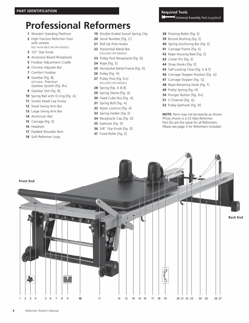
Professional Reformers1 Wooden Standing Platform
2 High-Traction Reformer Foot with wheels
NOT AVAILABLE ON SPX MODELS
3 1/2" Star Knob
4 Accessory Board Receptacle
5 Footbar Adjustment Cradle
6 Chrome Adjuster Bar
7 Comfort Footbar
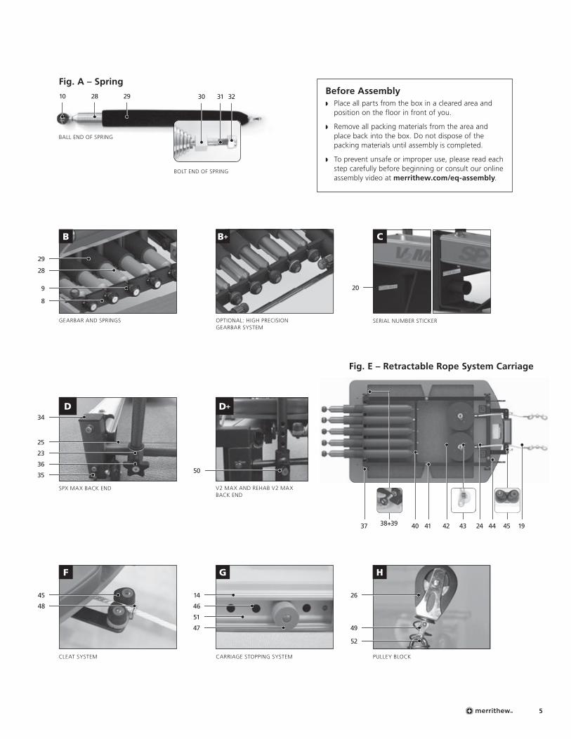
8 Gearbar [fig. B] OPTIONAL: Precision
Gearbar System [fig. B+]
9 Gearbar Slot [fig. B]
10 Spring Ball with O-ring [fig. A]
11 Socket Head Cap Screw
12 Small Swing Arm Bar
13 Large Swing Arm Bar
14 Aluminum Rail
15 Carriage [fig. E]
16 Headrest
17 Padded Shoulder Rest
18 Soft Reformer Loop
19 Double-Ended Swivel Spring Clip
20 Serial Number [fig. C]
21 Roll-Up Pole Hooks
22 Horizontal Metal Bar EXCLUDES SPX MODELS
23 Pulley Post Receptacle [fig. D]
24 Rope [fig. E]
25 Horizontal Metal Frame [fig. D]
26 Pulley [fig. H]
27 Pulley Post [fig. D+] EXCLUDES SPX MODELS
28 Spring [fig. A & B]
29 Spring Sleeve [fig. A]
30 Fixed Cube Nut [fig. A]
31 Spring Bolt [fig. A]
32 Nylon Locknut [fig. A]
33 Spring Holder [fig. E]
34 Receptacle Cap [fig. D]
35 Eyehook [fig. D]
36 3⁄8" Star Knob [fig. D]
37 Fixed Roller [fig. E]
38 Floating Roller [fig. E]
39 Bronze Bushing [fig. E]
40 Spring Anchoring Bar [fig. E]
41 Carriage Frame [fig. E]
42 Rope Housing Reel [fig. E]
43 Cotter Pin [fig. E]
44 Strap Hooks [fig. E]
45 Self-Locking Cleat [fig. E & F]
46 Carriage Stopper Position [fig. G]
47 Carriage Stopper [fig. G]
48 Rope Retaining Hook [fig. F]
49 Pulley Spring [fig. H]
50 Plunger Button [fig. D+]
51 C-Channel [fig. G]
52 Pulley Eyehook [fig. H]
NOTE: Parts may not be exactly as shown. Photo shown is a V2 Max Reformer. Part IDs are the same for all Reformers. Please see page 3 for Reformers included.
1 32 4 5 6 7 11 15 252114131298 1010
PART IDENTIFICATION
Front End
Back End
16 18 1917 20 22 2423 26 27
Required Tools Universal Assembly Tool (supplied)
5
D+
Fig. E – Retractable Rope System Carriage
38+39
V2 MAX AND REHAB V2 MAX BACK END
SPX MAX BACK END
SPX MAX BACK END
OPTIONAL: HIGH PRECISION GEARBAR SYSTEM
B
GEARBAR AND SPRINGS SERIAL NUMBER STICKER
D
G HF
PULLEY BLOCKCARRIAGE STOPPING SYSTEMCLEAT SYSTEM
37 40 41 4442 24 1943 45
BOLT END OF SPRING
Fig. A – Spring
28 29
BALL END OF SPRING
3130 3210
8
9
29
48 46
45 14 26
28
51
47 49
20
C
34
36
23
25
5035
52
B+
Before Assemblyw Place all parts from the box in a cleared area and
position on the floor in front of you.
w Remove all packing materials from the area and place back into the box. Do not dispose of the packing materials until assembly is completed.
w To prevent unsafe or improper use, please read each step carefully before beginning or consult our online assembly video at merrithew.com/eq-assembly.
Reformer Owner’s Manual6
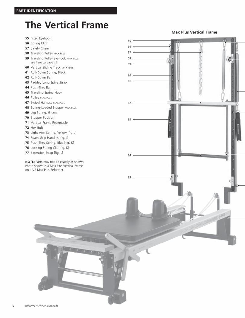
The Vertical Frame55 Fixed Eyehook
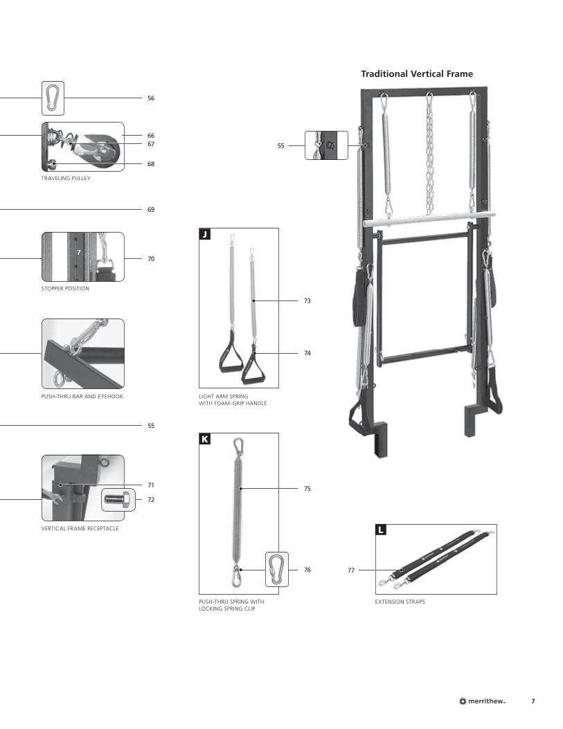
56 Spring Clip
57 Safety Chain
58 Traveling Pulley MAX PLUS
59 Traveling Pulley Eyehook MAX PLUS
see inset on page 19
60 Vertical Sliding Track MAX PLUS
61 Roll-Down Spring, Black
62 Roll-Down Bar
63 Padded Long Spine Strap
64 Push-Thru Bar
65 Traveling Spring Hook
66 Pulley MAX PLUS
67 Swivel Harness MAX PLUS
68 Spring-Loaded Stopper MAX PLUS
69 Leg Spring, Green
70 Stopper Position
71 Vertical Frame Receptacle
72 Hex Bolt
73 Light Arm Spring, Yellow [fig. J]
74 Foam-Grip Handles [fig. J]
75 Push-Thru Spring, Blue [fig. K]
76 Locking Spring Clip [fig. K]
77 Extension Strap [fig. L]
NOTE: Parts may not be exactly as shown. Photo shown is a Max Plus Vertical Frame on a V2 Max Plus Reformer.
Max Plus Vertical Frame
PART IDENTIFICATION
55
61
56
65
58
59
60
63
57
62
64
7
56
55
72
66
69
70
68
67
J
55
K
73
74
75
76
L
Traditional Vertical Frame
77
TRAVELING PULLEY
STOPPER POSITION
PUSH-THRU BAR AND EYEHOOK LIGHT ARM SPRING WITH FOAM-GRIP HANDLE
PUSH-THRU SPRING WITH LOCKING SPRING CLIP
EXTENSION STRAPS
VERTICAL FRAME RECEPTACLE
71
Reformer Owner’s Manual8
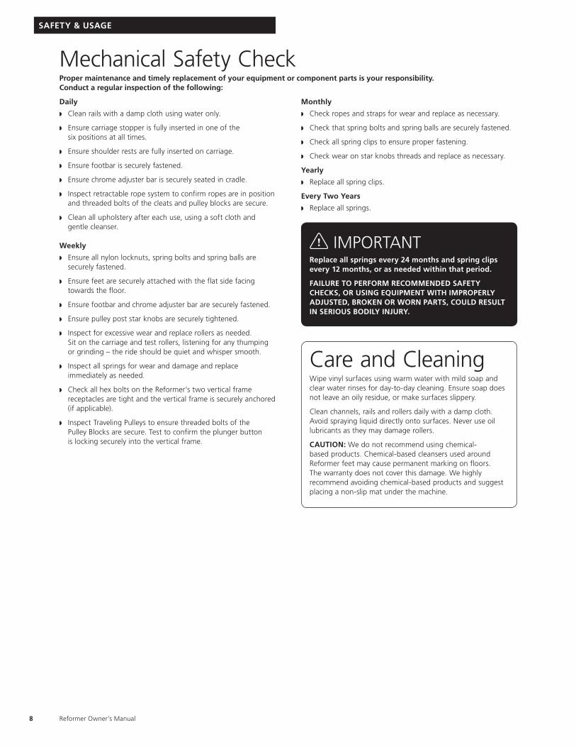
Mechanical Safety CheckProper maintenance and timely replacement of your equipment or component parts is your responsibility. Conduct a regular inspection of the following:
Daily
w Clean rails with a damp cloth using water only.
w Ensure carriage stopper is fully inserted in one of the six positions at all times.
w Ensure shoulder rests are fully inserted on carriage.
w Ensure footbar is securely fastened.
w Ensure chrome adjuster bar is securely seated in cradle.
w Inspect retractable rope system to confirm ropes are in position and threaded bolts of the cleats and pulley blocks are secure.
w Clean all upholstery after each use, using a soft cloth and gentle cleanser.
Weekly
w Ensure all nylon locknuts, spring bolts and spring balls are securely fastened.
w Ensure feet are securely attached with the flat side facing towards the floor.
w Ensure footbar and chrome adjuster bar are securely fastened.
w Ensure pulley post star knobs are securely tightened.
w Inspect for excessive wear and replace rollers as needed. Sit on the carriage and test rollers, listening for any thumping or grinding – the ride should be quiet and whisper smooth.
w Inspect all springs for wear and damage and replace immediately as needed.
w Check all hex bolts on the Reformer’s two vertical frame receptacles are tight and the vertical frame is securely anchored (if applicable).
w Inspect Traveling Pulleys to ensure threaded bolts of the Pulley Blocks are secure. Test to confirm the plunger button is locking securely into the vertical frame.
Monthly
w Check ropes and straps for wear and replace as necessary.
w Check that spring bolts and spring balls are securely fastened.
w Check all spring clips to ensure proper fastening.
w Check wear on star knobs threads and replace as necessary.
Yearly
w Replace all spring clips.
Every Two Years
w Replace all springs.
Care and CleaningWipe vinyl surfaces using warm water with mild soap and clear water rinses for day-to-day cleaning. Ensure soap does not leave an oily residue, or make surfaces slippery.
Clean channels, rails and rollers daily with a damp cloth. Avoid spraying liquid directly onto surfaces. Never use oil lubricants as they may damage rollers.
CAUTION: We do not recommend using chemical-based products. Chemical-based cleansers used around Reformer feet may cause permanent marking on floors. The warranty does not cover this damage. We highly recommend avoiding chemical-based products and suggest placing a non-slip mat under the machine.
SAFETY & USAGE
IMPORTANTReplace all springs every 24 months and spring clips every 12 months, or as needed within that period.
FAILURE TO PERFORM RECOMMENDED SAFETY CHECKS, OR USING EQUIPMENT WITH IMPROPERLY ADJUSTED, BROKEN OR WORN PARTS, COULD RESULT IN SERIOUS BODILY INJURY.
Prepare Rails Insert Carriage Stopper
Insert CarriageInsert Gearbar
Insert Pulley Posts
6 5 4 3 2 1
9
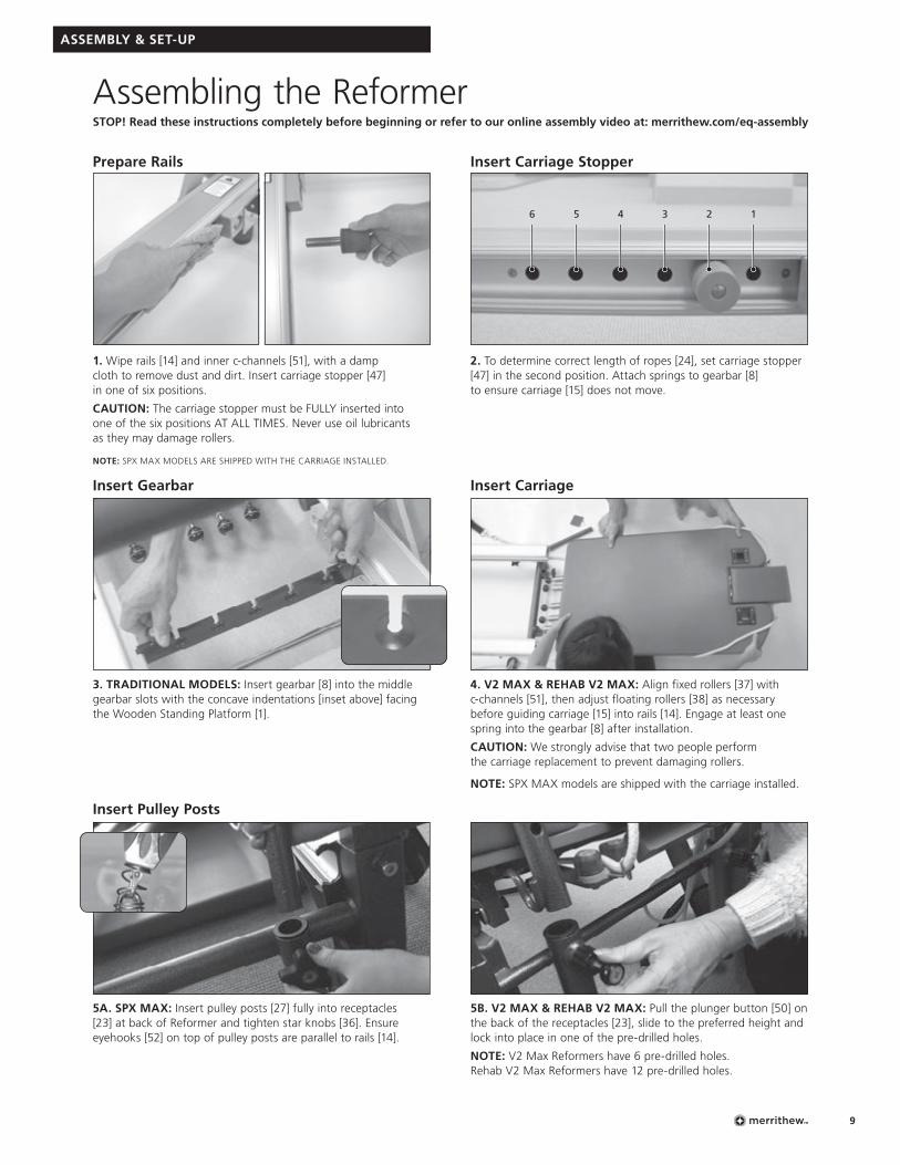
Assembling the ReformerSTOP! Read these instructions completely before beginning or refer to our online assembly video at: merrithew.com/eq-assembly
ASSEMBLY & SET-UP
1. Wipe rails [14] and inner c-channels [51], with a damp cloth to remove dust and dirt. Insert carriage stopper [47] in one of six positions.
CAUTION: The carriage stopper must be FULLY inserted into one of the six positions AT ALL TIMES. Never use oil lubricants as they may damage rollers.
NOTE: SPX MAX MODELS ARE SHIPPED WITH THE CARRIAGE INSTALLED.
4. V2 MAX & REHAB V2 MAX: Align fixed rollers [37] with c-channels [51], then adjust floating rollers [38] as necessary before guiding carriage [15] into rails [14]. Engage at least one spring into the gearbar [8] after installation.
CAUTION: We strongly advise that two people perform the carriage replacement to prevent damaging rollers.
NOTE: SPX MAX models are shipped with the carriage installed.
5A. SPX MAX: Insert pulley posts [27] fully into receptacles [23] at back of Reformer and tighten star knobs [36]. Ensure eyehooks [52] on top of pulley posts are parallel to rails [14].
3. TRADITIONAL MODELS: Insert gearbar [8] into the middle gearbar slots with the concave indentations [inset above] facing the Wooden Standing Platform [1].
5B. V2 MAX & REHAB V2 MAX: Pull the plunger button [50] on the back of the receptacles [23], slide to the preferred height and lock into place in one of the pre-drilled holes.
NOTE: V2 Max Reformers have 6 pre-drilled holes. Rehab V2 Max Reformers have 12 pre-drilled holes.
2. To determine correct length of ropes [24], set carriage stopper [47] in the second position. Attach springs to gearbar [8] to ensure carriage [15] does not move.
Adjust RopesInsert Shoulder Rests
Reformer Owner’s Manual10
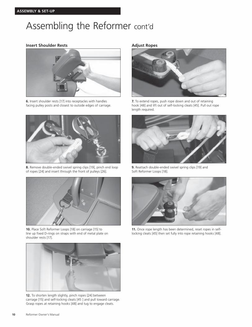
6. Insert shoulder rests [17] into receptacles with handles facing pulley posts and closest to outside edges of carriage.
8. Remove double-ended swivel spring clips [19], pinch end loop of ropes [24] and insert through the front of pulleys [26].
10. Place Soft Reformer Loops [18] on carriage [15] to line up fixed D-rings on straps with end of metal plate on shoulder rests [17].
12. To shorten length slightly, pinch ropes [24] between carriage [15] and self-locking cleats [45 ] and pull toward carriage. Grasp ropes at retaining hooks [48] and tug to engage cleats.
7. To extend ropes, push rope down and out of retaining hook [48] and lift out of self-locking cleats [45]. Pull out rope length required.
9. Reattach double-ended swivel spring clips [19] and Soft Reformer Loops [18].
11. Once rope length has been determined, reset ropes in self-locking cleats [45] then set fully into rope retaining hooks [48].
ASSEMBLY & SET-UP
Assembling the Reformer cont’d
11
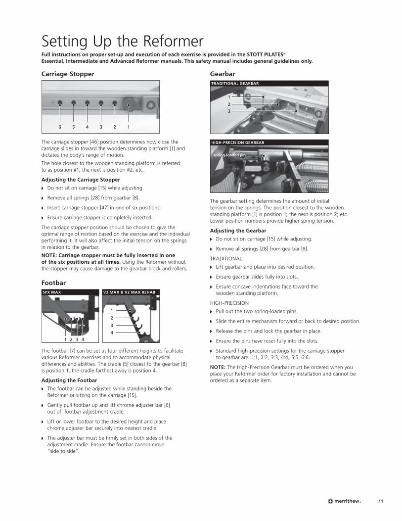
Carriage Stopper
6 5 4 3 2 1
The carriage stopper [46] position determines how close the carriage slides in toward the wooden standing platform [1] and dictates the body’s range of motion.
The hole closest to the wooden standing platform is referred to as position #1; the next is position #2, etc.
Adjusting the Carriage Stopper
w Do not sit on carriage [15] while adjusting.
w Remove all springs [28] from gearbar [8].
w Insert carriage stopper [47] in one of six positions.
w Ensure carriage stopper is completely inserted.
The carriage stopper position should be chosen to give the optimal range of motion based on the exercise and the individual performing it. It will also affect the initial tension on the springs in relation to the gearbar.
NOTE: Carriage stopper must be fully inserted in one of the six positions at all times. Using the Reformer without the stopper may cause damage to the gearbar block and rollers.
Footbar V2 MAX & V2 MAX REHAB
1
2
3
4
SPX MAX
1 432
The footbar [7] can be set at four different heights to facilitate various Reformer exercises and to accommodate physical differences and abilities. The cradle [5] closest to the gearbar [8] is position 1, the cradle farthest away is position 4.
Adjusting the Footbar
w The footbar can be adjusted while standing beside the Reformer or sitting on the carriage [15].
w Gently pull footbar up and lift chrome adjuster bar [6] out of footbar adjustment cradle.
w Lift or lower footbar to the desired height and place chrome adjuster bar securely into nearest cradle.
w The adjuster bar must be firmly set in both sides of the adjustment cradle. Ensure the footbar cannot move “side to side”.
Gearbar
1
2
3
TRADITIONAL GEARBAR
HIGH-PRECISION GEARBAR
The gearbar setting determines the amount of initial tension on the springs. The position closest to the wooden standing platform [1] is position 1; the next is position 2; etc. Lower position numbers provide higher spring tension.
Adjusting the Gearbar
w Do not sit on carriage [15] while adjusting.
w Remove all springs [28] from gearbar [8].
TRADITIONAL
w Lift gearbar and place into desired position.
w Ensure gearbar slides fully into slots.
w Ensure concave indentations face toward the wooden standing platform.
HIGH-PRECISION
w Pull out the two spring-loaded pins.
w Slide the entire mechanism forward or back to desired position.
w Release the pins and lock the gearbar in place.
w Ensure the pins have reset fully into the slots.
w Standard high-precision settings for the carriage stopper to gearbar are: 1:1, 2:2, 3:3, 4:4, 5:5, 6:6.
NOTE: The High-Precision Gearbar must be ordered when you place your Reformer order for factory installation and cannot be ordered as a separate item.
Setting Up the ReformerFull instructions on proper set-up and execution of each exercise is provided in the STOTT PILATES® Essential, Intermediate and Advanced Reformer manuals. This safety manual includes general guidelines only.
spring-loaded pin
Reformer Owner’s Manual12
Retractable Rope System
Prior to use, confirm that the retractable rope system is in good order and rope [24] is secured through self-locking cleats [45] and rope retaining hook [48]. (See Assembly Instructions on page 9.)
Springs
The number of springs [28] attached to the gearbar [8] determines the total amount of resistance. Reformers are shipped with High-Precision Springs (one 25%, one 50%, and three 100%-tension springs). See page 24 for more details and available spring packages.
Adjusting Springs
w Take care when attaching and detaching springs.
w For safety, place one hand on gearbar.
w Firmly grasp spring, (not spring ball), and stretch it to hook to or unhook from gearbar.
w Ensure ball rests securely in concave indentations of gearbar.
Headrest
adjustment block
The headrest [16] adjusts to three positions: flat, half-raised or fully raised. It should be adjusted on an individual basis to ensure neck and shoulders are comfortable and tension-free when lying supine.
In exercises where the hips are lifted higher than the shoulders, the headrest should be flat – even when beginning from a supine position. In some exercises it is raised to provide a brace for the feet.
Adjusting the Headrest
w With no weight on headrest, lift it and hinge adjustment block to rest securely onto wooden edge of carriage.
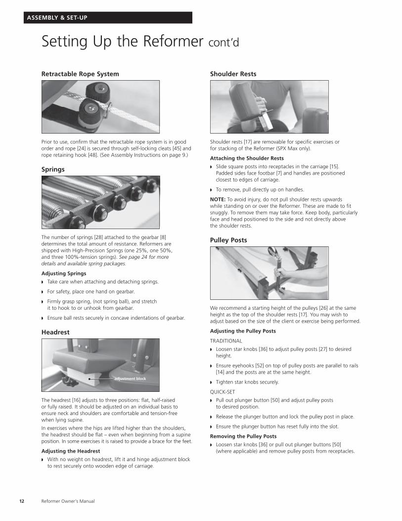
Shoulder Rests
Shoulder rests [17] are removable for specific exercises or for stacking of the Reformer (SPX Max only).
Attaching the Shoulder Rests
w Slide square posts into receptacles in the carriage [15]. Padded sides face footbar [7] and handles are positioned closest to edges of carriage.
w To remove, pull directly up on handles.
NOTE: To avoid injury, do not pull shoulder rests upwards while standing on or over the Reformer. These are made to fit snuggly. To remove them may take force. Keep body, particularly face and head positioned to the side and not directly above the shoulder rests.
Pulley Posts
We recommend a starting height of the pulleys [26] at the same height as the top of the shoulder rests [17]. You may wish to adjust based on the size of the client or exercise being performed.
Adjusting the Pulley Posts
TRADITIONAL
w Loosen star knobs [36] to adjust pulley posts [27] to desired height.
w Ensure eyehooks [52] on top of pulley posts are parallel to rails [14] and the posts are at the same height.
w Tighten star knobs securely.
QUICK-SET
w Pull out plunger button [50] and adjust pulley posts to desired position.
w Release the plunger button and lock the pulley post in place.
w Ensure the plunger button has reset fully into the slot.
Removing the Pulley Posts
w Loosen star knobs [36] or pull out plunger buttons [50] (where applicable) and remove pulley posts from receptacles.
Setting Up the Reformer cont’d
ASSEMBLY & SET-UP
13
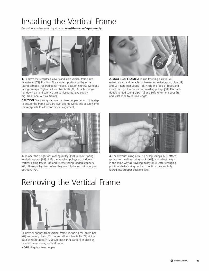
2. MAX PLUS FRAMES: To use traveling pulleys [58] extend ropes and detach double-ended swivel spring clips [19] and Soft Reformer Loops [18]. Pinch end loop of ropes and insert through the bottom of traveling pulleys [58]. Reattach double-ended spring clips [19] and Soft Reformer Loops [18] and reset rope to desired length.
1. Remove the receptacle covers and slide vertical frame into receptacles [71]. For Max Plus models, position pulley system facing carriage. For traditional models, position highest eyehooks facing carriage. Tighten all four hex bolts [72]. Attach springs, roll-down bar and safety chain as illustrated. See page 7 [fig. Traditional vertical frame].
CAUTION: We strongly advise that two people perform this step to ensure the frame bars are level and fit evenly and securely into the receptacle to allow for proper alignment.
3. To alter the height of traveling pulleys [58], pull out spring-loaded stoppers [68]. Shift the traveling pulleys up or down vertical sliding tracks [60] and release spring-loaded stoppers [68]. Shake pulleys to confirm they are fully locked into stopper positions [70].
Remove all springs from vertical frame, including roll-down bar [62] and safety chain [57]. Loosen all four hex bolts [72] at the base of receptacles [71]. Secure push-thru bar [64] in place by hand while removing vertical frame.
NOTE: Requires two people.
4. For exercises using arm [73] or leg springs [69], attach springs to traveling spring hooks [65], and adjust height in the same way as traveling pulleys [58]. After changing position, shake spring hooks to confirm they are fully locked into stopper positions [70].
Installing the Vertical FrameConsult our online assembly video at merrithew.com/eq-assembly
Removing the Vertical Frame
Reformer Owner’s Manual14
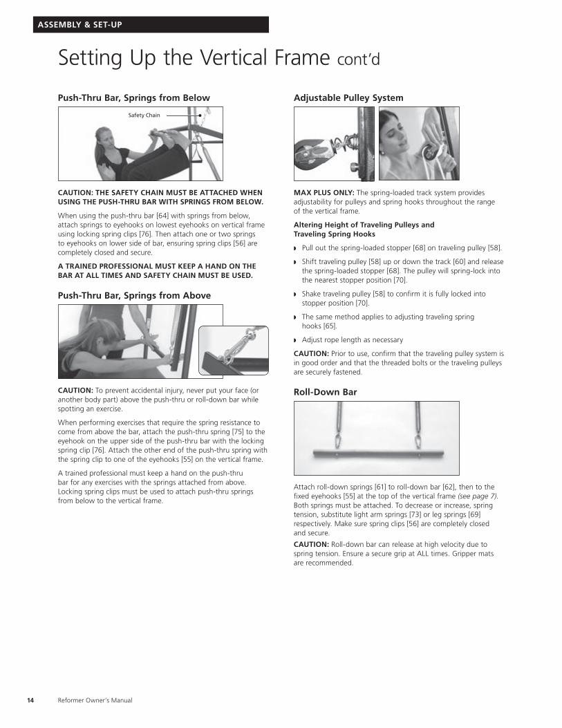
Push-Thru Bar, Springs from Below
Safety Chain
CAUTION: THE SAFETY CHAIN MUST BE ATTACHED WHEN USING THE PUSH-THRU BAR WITH SPRINGS FROM BELOW.
When using the push-thru bar [64] with springs from below, attach springs to eyehooks on lowest eyehooks on vertical frame using locking spring clips [76]. Then attach one or two springs to eyehooks on lower side of bar, ensuring spring clips [56] are completely closed and secure.
A TRAINED PROFESSIONAL MUST KEEP A HAND ON THE BAR AT ALL TIMES AND SAFETY CHAIN MUST BE USED.
Push-Thru Bar, Springs from Above
CAUTION: To prevent accidental injury, never put your face (or another body part) above the push-thru or roll-down bar while spotting an exercise.
When performing exercises that require the spring resistance to come from above the bar, attach the push-thru spring [75] to the eyehook on the upper side of the push-thru bar with the locking spring clip [76]. Attach the other end of the push-thru spring with the spring clip to one of the eyehooks [55] on the vertical frame.
A trained professional must keep a hand on the push-thru bar for any exercises with the springs attached from above. Locking spring clips must be used to attach push-thru springs from below to the vertical frame.
Adjustable Pulley System
MAX PLUS ONLY: The spring-loaded track system provides adjustability for pulleys and spring hooks throughout the range of the vertical frame.
Altering Height of Traveling Pulleys and Traveling Spring Hooks
w Pull out the spring-loaded stopper [68] on traveling pulley [58].
w Shift traveling pulley [58] up or down the track [60] and release the spring-loaded stopper [68]. The pulley will spring-lock into the nearest stopper position [70].
w Shake traveling pulley [58] to confirm it is fully locked into stopper position [70].
w The same method applies to adjusting traveling spring hooks [65].
w Adjust rope length as necessary
CAUTION: Prior to use, confirm that the traveling pulley system is in good order and that the threaded bolts or the traveling pulleys are securely fastened.
Roll-Down Bar
Attach roll-down springs [61] to roll-down bar [62], then to the fixed eyehooks [55] at the top of the vertical frame (see page 7). Both springs must be attached. To decrease or increase, spring tension, substitute light arm springs [73] or leg springs [69]respectively. Make sure spring clips [56] are completely closed and secure.
CAUTION: Roll-down bar can release at high velocity due to spring tension. Ensure a secure grip at ALL times. Gripper mats are recommended.
Setting Up the Vertical Frame cont’d
ASSEMBLY & SET-UP
15
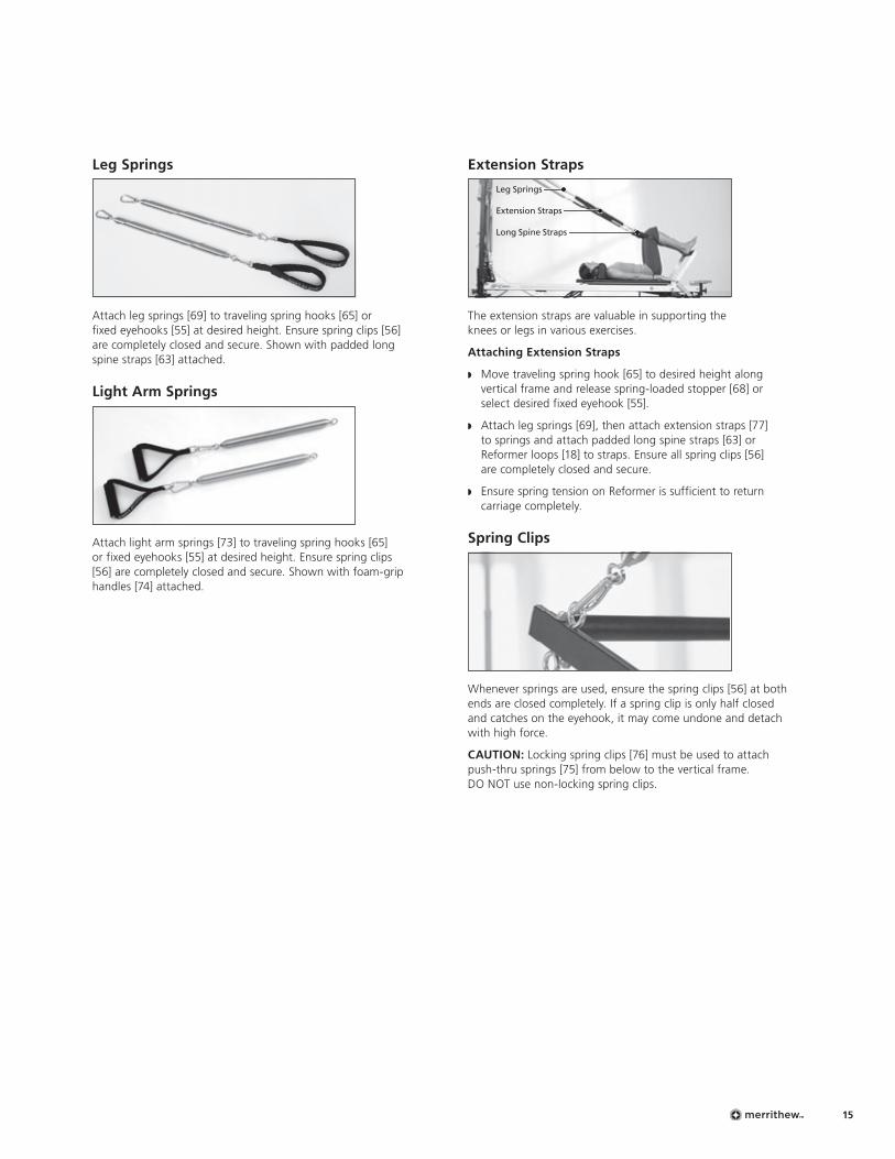
Leg Springs
Attach leg springs [69] to traveling spring hooks [65] or fixed eyehooks [55] at desired height. Ensure spring clips [56] are completely closed and secure. Shown with padded long spine straps [63] attached.
Light Arm Springs
Attach light arm springs [73] to traveling spring hooks [65] or fixed eyehooks [55] at desired height. Ensure spring clips [56] are completely closed and secure. Shown with foam-grip handles [74] attached.
Extension Straps
Leg Springs
Extension Straps
Long Spine Straps
The extension straps are valuable in supporting the knees or legs in various exercises.
Attaching Extension Straps
w Move traveling spring hook [65] to desired height along vertical frame and release spring-loaded stopper [68] or select desired fixed eyehook [55].
w Attach leg springs [69], then attach extension straps [77] to springs and attach padded long spine straps [63] or Reformer loops [18] to straps. Ensure all spring clips [56] are completely closed and secure.
w Ensure spring tension on Reformer is sufficient to return carriage completely.
Spring Clips
Whenever springs are used, ensure the spring clips [56] at both ends are closed completely. If a spring clip is only half closed and catches on the eyehook, it may come undone and detach with high force.
CAUTION: Locking spring clips [76] must be used to attach push-thru springs [75] from below to the vertical frame. DO NOT use non-locking spring clips.
Reformer Owner’s Manual16
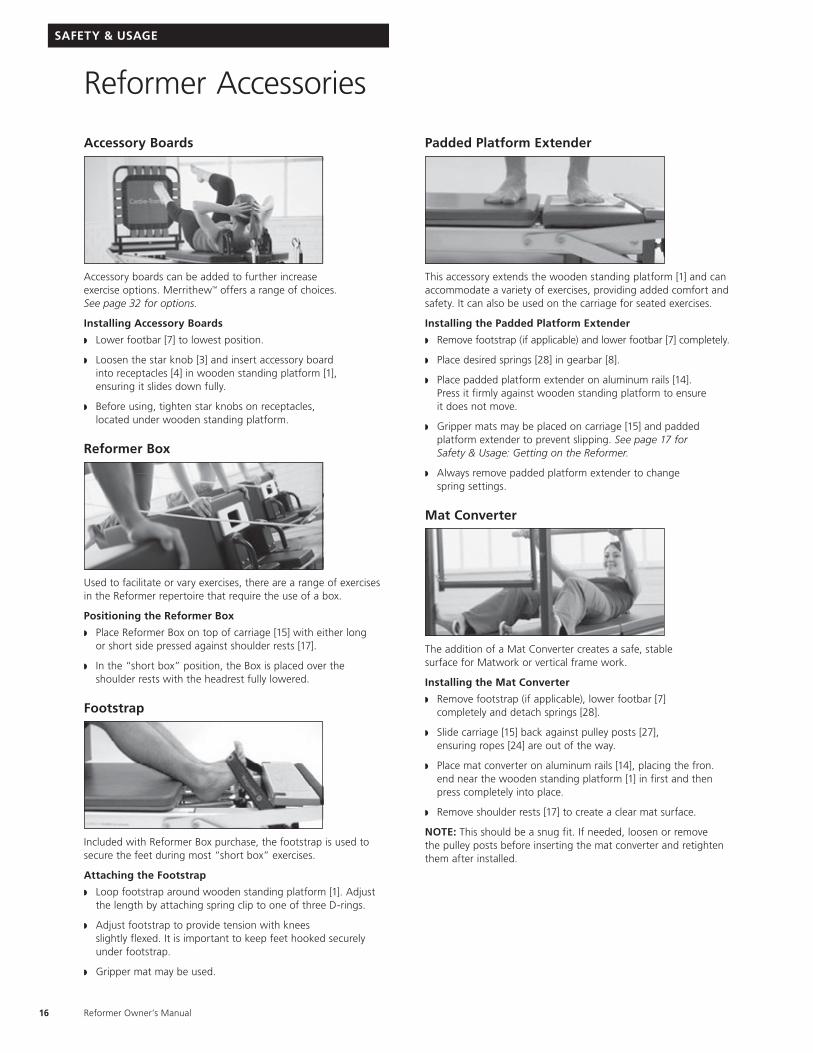
Accessory Boards
Accessory boards can be added to further increase exercise options. Merrithew™ offers a range of choices. See page 32 for options.
Installing Accessory Boards
w Lower footbar [7] to lowest position.
w Loosen the star knob [3] and insert accessory board into receptacles [4] in wooden standing platform [1], ensuring it slides down fully.
w Before using, tighten star knobs on receptacles, located under wooden standing platform.
Reformer Box
Used to facilitate or vary exercises, there are a range of exercises in the Reformer repertoire that require the use of a box.
Positioning the Reformer Box
w Place Reformer Box on top of carriage [15] with either long or short side pressed against shoulder rests [17].
w In the “short box” position, the Box is placed over the shoulder rests with the headrest fully lowered.
Footstrap
Included with Reformer Box purchase, the footstrap is used to secure the feet during most “short box” exercises.
Attaching the Footstrap
w Loop footstrap around wooden standing platform [1]. Adjust the length by attaching spring clip to one of three D-rings.
w Adjust footstrap to provide tension with knees slightly flexed. It is important to keep feet hooked securely under footstrap.
w Gripper mat may be used.
Padded Platform Extender
This accessory extends the wooden standing platform [1] and can accommodate a variety of exercises, providing added comfort and safety. It can also be used on the carriage for seated exercises.
Installing the Padded Platform Extender
w Remove footstrap (if applicable) and lower footbar [7] completely.
w Place desired springs [28] in gearbar [8].
w Place padded platform extender on aluminum rails [14]. Press it firmly against wooden standing platform to ensure it does not move.
w Gripper mats may be placed on carriage [15] and padded platform extender to prevent slipping. See page 17 for Safety & Usage: Getting on the Reformer.
w Always remove padded platform extender to change spring settings.
Mat Converter
The addition of a Mat Converter creates a safe, stable surface for Matwork or vertical frame work.
Installing the Mat Converter
w Remove footstrap (if applicable), lower footbar [7] completely and detach springs [28].
w Slide carriage [15] back against pulley posts [27], ensuring ropes [24] are out of the way.
w Place mat converter on aluminum rails [14], placing the fron. end near the wooden standing platform [1] in first and then press completely into place.
w Remove shoulder rests [17] to create a clear mat surface.
NOTE: This should be a snug fit. If needed, loosen or remove the pulley posts before inserting the mat converter and retighten them after installed.
Reformer Accessories
SAFETY & USAGE
17
1
3
2
4
Getting on the ReformerSTOP! Before getting on, ensure the carriage stopper is inserted and at least one spring is securely attached to the gearbar.
Standing or Kneeling PositionsThe carriage is a moving platform. Special attention must always be paid to maintaining your balance and stability, especially when performing kneeling or standing exercises.
When standing on the carriage with two feet, it is advisable to have a spotter to steady the carriage.
1. Before you begin, ensure the carriage stopper is inserted and that one or more springs are engaged in the gearbar to secure the carriage.
2. Step carefully with one foot onto wooden standing platform.
3. Place other foot carefully onto the carriage. A gripper mat may be used to prevent slipping. (Gripper mat not supplied, see optional accessories, page 33).
For SPX Reformers Place one foot on secured carriage. Carefully place other foot onto the wooden standing platform. A Gripper Mat may be used to prevent slipping.
Never attempt to get on the SPX Reformer by stepping on the wooden standing platform. Never stand with both feet on wooden standing platform.
Secure Hands and FeetWhenever placing hands or feet on the footbar, shoulder rests or headrest, ensure they will not slip during exercise. Gripper mats may be used.
Sitting or Lying on a BoxAlways place Reformer Box in a stable position on the Reformer and sit directly in the middle to avoid tipping. When using footstrap, ensure it is underneath the wooden standing platform and securely clipped together.
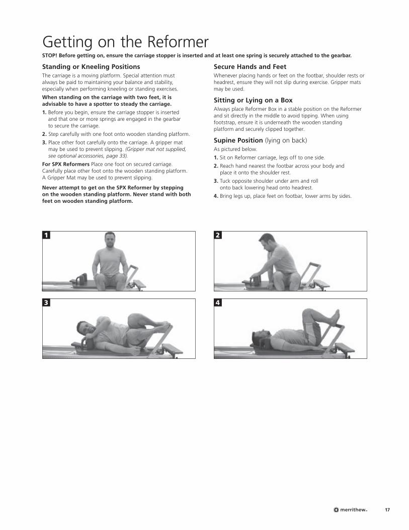
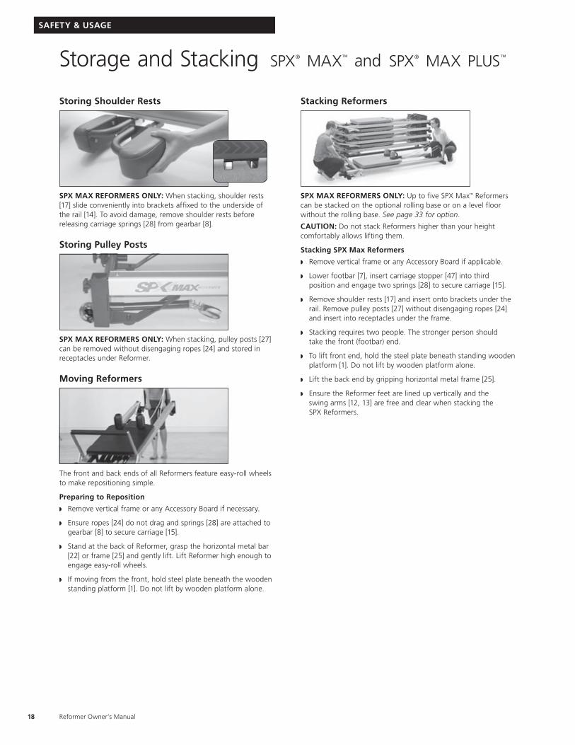
Supine Position (lying on back)As pictured below.
1. Sit on Reformer carriage, legs off to one side.
2. Reach hand nearest the footbar across your body and place it onto the shoulder rest.
3. Tuck opposite shoulder under arm and roll onto back lowering head onto headrest.
4. Bring legs up, place feet on footbar, lower arms by sides.
Reformer Owner’s Manual18
Storing Shoulder Rests
SPX MAX REFORMERS ONLY: When stacking, shoulder rests [17] slide conveniently into brackets affixed to the underside of the rail [14]. To avoid damage, remove shoulder rests before releasing carriage springs [28] from gearbar [8].
Storing Pulley Posts
SPX MAX REFORMERS ONLY: When stacking, pulley posts [27] can be removed without disengaging ropes [24] and stored in receptacles under Reformer.
Moving Reformers
The front and back ends of all Reformers feature easy-roll wheels to make repositioning simple.
Preparing to Reposition
w Remove vertical frame or any Accessory Board if necessary.
w Ensure ropes [24] do not drag and springs [28] are attached to gearbar [8] to secure carriage [15].
w Stand at the back of Reformer, grasp the horizontal metal bar [22] or frame [25] and gently lift. Lift Reformer high enough to engage easy-roll wheels.
w If moving from the front, hold steel plate beneath the wooden standing platform [1]. Do not lift by wooden platform alone.
Stacking Reformers
SPX MAX REFORMERS ONLY: Up to five SPX Max™ Reformers can be stacked on the optional rolling base or on a level floor without the rolling base. See page 33 for option.
CAUTION: Do not stack Reformers higher than your height comfortably allows lifting them.
Stacking SPX Max Reformers
w Remove vertical frame or any Accessory Board if applicable.
w Lower footbar [7], insert carriage stopper [47] into third position and engage two springs [28] to secure carriage [15].
w Remove shoulder rests [17] and insert onto brackets under the rail. Remove pulley posts [27] without disengaging ropes [24] and insert into receptacles under the frame.
w Stacking requires two people. The stronger person should take the front (footbar) end.
w To lift front end, hold the steel plate beneath standing wooden platform [1]. Do not lift by wooden platform alone.
w Lift the back end by gripping horizontal metal frame [25].
w Ensure the Reformer feet are lined up vertically and the swing arms [12, 13] are free and clear when stacking the SPX Reformers.
Storage and Stacking spx® max™ and spx® max plus™
SAFETY & USAGE
19
SPX REFORMER WITH VERTICAL STAND
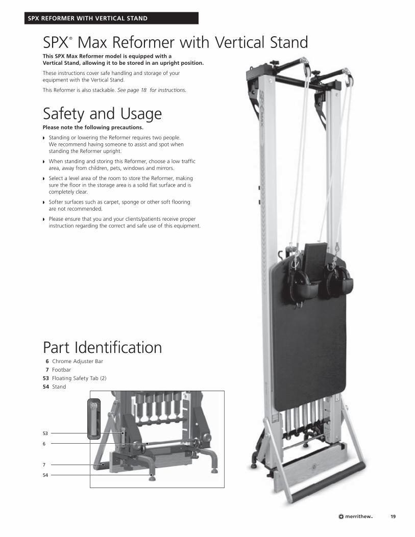
SPX® Max Reformer with Vertical StandThis SPX Max Reformer model is equipped with a Vertical Stand, allowing it to be stored in an upright position.
These instructions cover safe handling and storage of your equipment with the Vertical Stand.
This Reformer is also stackable. See page 18 for instructions.
Safety and UsagePlease note the following precautions.
w Standing or lowering the Reformer requires two people. We recommend having someone to assist and spot when standing the Reformer upright.
w When standing and storing this Reformer, choose a low traffic area, away from children, pets, windows and mirrors.
w Select a level area of the room to store the Reformer, making sure the floor in the storage area is a solid flat surface and is completely clear.
w Softer surfaces such as carpet, sponge or other soft flooring are not recommended.
w Please ensure that you and your clients/patients receive proper instruction regarding the correct and safe use of this equipment.
Part Identification6 Chrome Adjuster Bar
7 Footbar
53 Floating Safety Tab (2)
54 Stand
53
7
54
6
Reformer Owner’s Manual20
SPX REFORMER WITH VERTICAL STAND
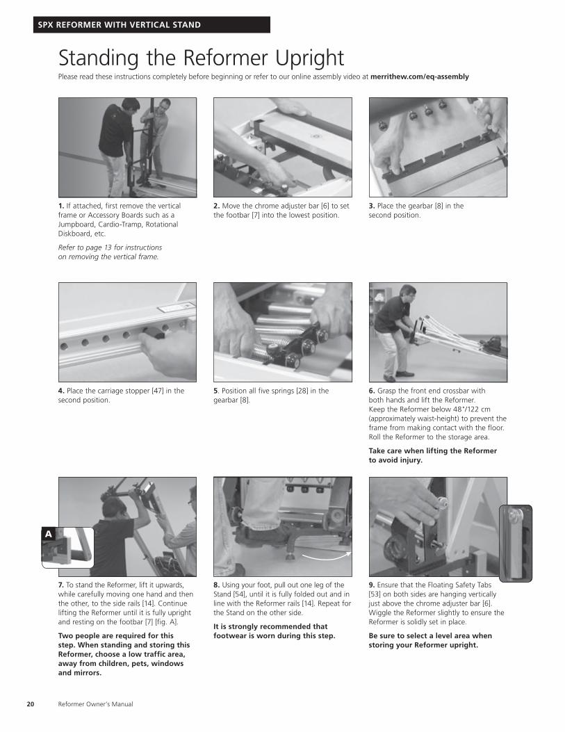
Standing the Reformer UprightPlease read these instructions completely before beginning or refer to our online assembly video at merrithew.com/eq-assembly
2. Move the chrome adjuster bar [6] to set the footbar [7] into the lowest position.
5. Position all five springs [28] in the gearbar [8].
8. Using your foot, pull out one leg of the Stand [54], until it is fully folded out and in line with the Reformer rails [14]. Repeat for the Stand on the other side.
It is strongly recommended that footwear is worn during this step.
9. Ensure that the Floating Safety Tabs [53] on both sides are hanging vertically just above the chrome adjuster bar [6]. Wiggle the Reformer slightly to ensure the Reformer is solidly set in place.
Be sure to select a level area when storing your Reformer upright.
1. If attached, first remove the vertical frame or Accessory Boards such as a Jumpboard, Cardio-Tramp, Rotational Diskboard, etc.
Refer to page 13 for instructions on removing the vertical frame.
4. Place the carriage stopper [47] in the second position.
7. To stand the Reformer, lift it upwards, while carefully moving one hand and then the other, to the side rails [14]. Continue lifting the Reformer until it is fully upright and resting on the footbar [7] [fig. A].
Two people are required for this step. When standing and storing this Reformer, choose a low traffic area, away from children, pets, windows and mirrors.
3. Place the gearbar [8] in the second position.
6. Grasp the front end crossbar with both hands and lift the Reformer. Keep the Reformer below 48"/122 cm (approximately waist-height) to prevent the frame from making contact with the floor. Roll the Reformer to the storage area.
Take care when lifting the Reformer to avoid injury.
A
21
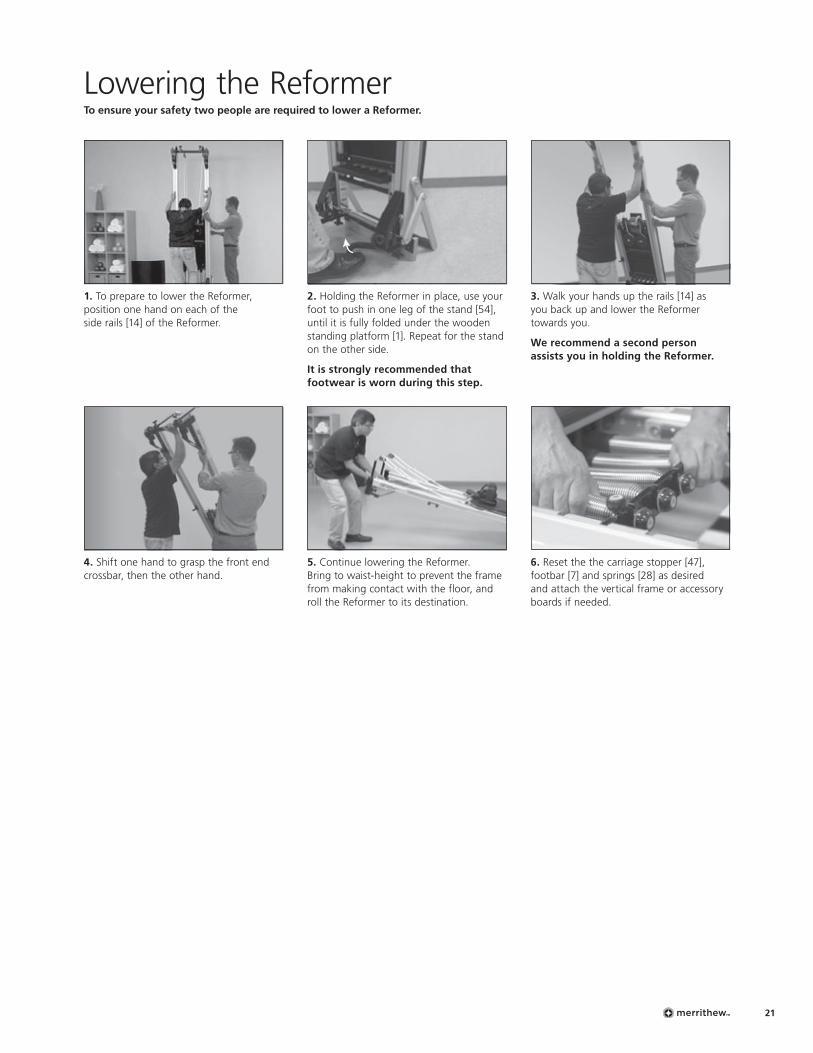
Lowering the ReformerTo ensure your safety two people are required to lower a Reformer.
2. Holding the Reformer in place, use your foot to push in one leg of the stand [54], until it is fully folded under the wooden standing platform [1]. Repeat for the stand on the other side.
It is strongly recommended that footwear is worn during this step.
5. Continue lowering the Reformer. Bring to waist-height to prevent the frame from making contact with the floor, and roll the Reformer to its destination.
1. To prepare to lower the Reformer, position one hand on each of the side rails [14] of the Reformer.
4. Shift one hand to grasp the front end crossbar, then the other hand.
3. Walk your hands up the rails [14] as you back up and lower the Reformer towards you.
We recommend a second person assists you in holding the Reformer.
6. Reset the the carriage stopper [47], footbar [7] and springs [28] as desired and attach the vertical frame or accessory boards if needed.
Reformer Owner’s Manual22
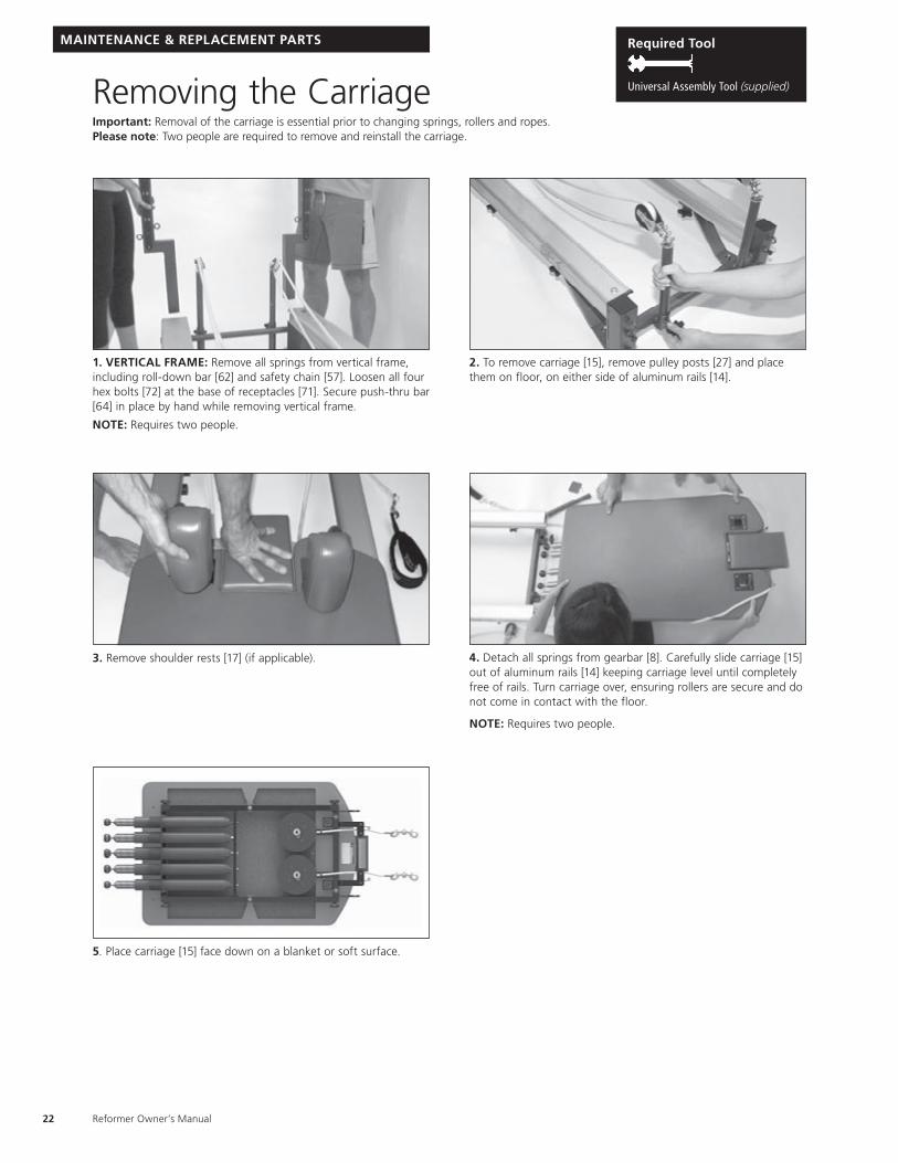
Removing the CarriageImportant: Removal of the carriage is essential prior to changing springs, rollers and ropes. Please note: Two people are required to remove and reinstall the carriage.
1. VERTICAL FRAME: Remove all springs from vertical frame, including roll-down bar [62] and safety chain [57]. Loosen all four hex bolts [72] at the base of receptacles [71]. Secure push-thru bar [64] in place by hand while removing vertical frame.
NOTE: Requires two people.
3. Remove shoulder rests [17] (if applicable). 4. Detach all springs from gearbar [8]. Carefully slide carriage [15] out of aluminum rails [14] keeping carriage level until completely free of rails. Turn carriage over, ensuring rollers are secure and do not come in contact with the floor.
NOTE: Requires two people.
2. To remove carriage [15], remove pulley posts [27] and place them on floor, on either side of aluminum rails [14].
5. Place carriage [15] face down on a blanket or soft surface.
MAINTENANCE & REPLACEMENT PARTS Required Tool
Universal Assembly Tool (supplied)
23
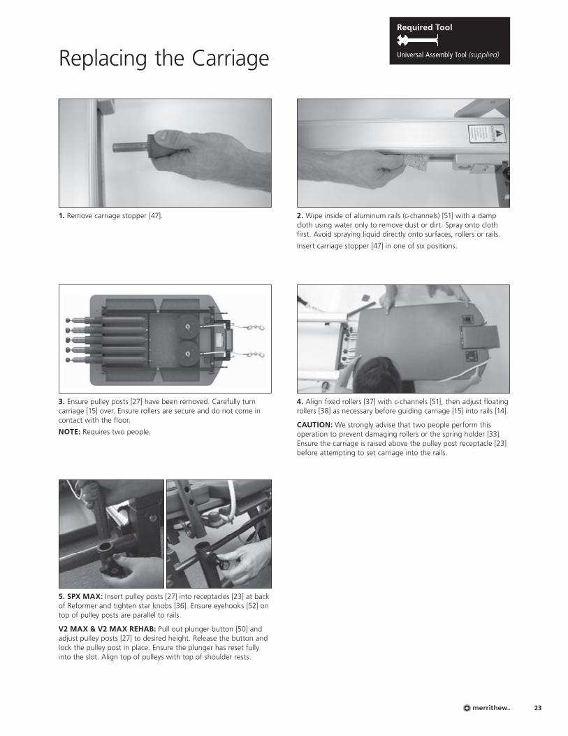
Replacing the Carriage
1. Remove carriage stopper [47].
4. Align fixed rollers [37] with c-channels [51], then adjust floating rollers [38] as necessary before guiding carriage [15] into rails [14].
CAUTION: We strongly advise that two people perform this operation to prevent damaging rollers or the spring holder [33]. Ensure the carriage is raised above the pulley post receptacle [23] before attempting to set carriage into the rails.
2. Wipe inside of aluminum rails (c-channels) [51] with a damp cloth using water only to remove dust or dirt. Spray onto cloth first. Avoid spraying liquid directly onto surfaces, rollers or rails.
Insert carriage stopper [47] in one of six positions.
3. Ensure pulley posts [27] have been removed. Carefully turn carriage [15] over. Ensure rollers are secure and do not come in contact with the floor.
NOTE: Requires two people.
5. SPX MAX: Insert pulley posts [27] into receptacles [23] at back of Reformer and tighten star knobs [36]. Ensure eyehooks [52] on top of pulley posts are parallel to rails.
V2 MAX & V2 MAX REHAB: Pull out plunger button [50] and adjust pulley posts [27] to desired height. Release the button and lock the pulley post in place. Ensure the plunger has reset fully into the slot. Align top of pulleys with top of shoulder rests.
Required Tool
Universal Assembly Tool (supplied)

black blue red black black
Reformer Owner’s Manual24
Spring Replacement Packages and SleevesTo ensure your Merrithew™ equipment works at its optimum level, as well as to ensure safety for you or your client, it is recommended that all springs are replaced every two years
Springs come in four different strengths to al. an individual customized workout. Everyone — from a client using a 25% spring to rehabilitate a shoulder injury to an elite athlete using the 125% spring to maximize their workout — can get the most out of the equipment.
Refer to the spring package details below to determine the right spring package for your needs. It is imperative to have the equipment’s serial number available when placing your spring replacement order.
Power Up Spring Package3 × 125%, 1 × 100%, 1 × 50% arrange as follows:
Place the red (100%) spring in the center, and the blue (50%) spring to one side. Place black (125%) springs in the remaining positions.
red red blue red red
Traditional Spring Package4 × 100%, 1 × 50% arrange as follows:
Place the blue (50%) spring in the center and two red (100%) springs on either side.
red white blue red red
High-Precision Spring Package3 × 100%, 1 × 50%, 1 × 25% arrange as follows:
Place the blue (50%) spring in the center, and the white (25%) spring to one side. Place red (100%) springs in remaining positions.
Determine desired replacement spring package.Springs balls are color-coded. Black = 125%, Red = 100%, Blue = 50%, White = 25%
Spring Sleeves are required for proper function of the Reformer if it features a spring holder.
MAINTENANCE & REPLACEMENT PARTS
25
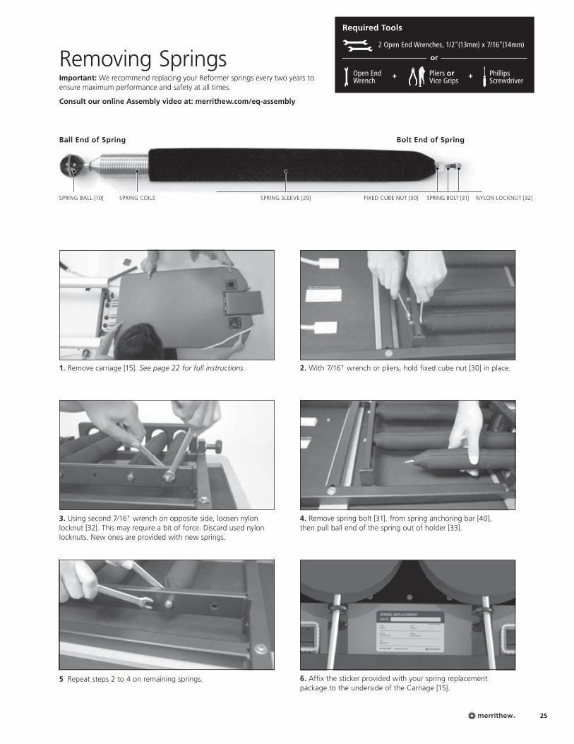
3. Using second 7⁄16" wrench on opposite side, loosen nylon locknut [32]. This may require a bit of force. Discard used nylon locknuts. New ones are provided with new springs.
5 Repeat steps 2 to 4 on remaining springs.
4. Remove spring bolt [31]. from spring anchoring bar [40], then pull ball end of the spring out of holder [33].
2. With 7/16" wrench or pliers, hold fixed cube nut [30] in place.1. Remove carriage [15]. See page 22 for full instructions.
Removing SpringsImportant: We recommend replacing your Reformer springs every two years to ensure maximum performance and safety at all times.
Consult our online Assembly video at: merrithew.com/eq-assembly
Bolt End of SpringBall End of Spring
NYLON LOCKNUT [32]SPRING BALL [10] SPRING COILS SPRING SLEEVE [29] SPRING BOLT [31]FIXED CUBE NUT [30]
6. Affix the sticker provided with your spring replacement package to the underside of the Carriage [15].
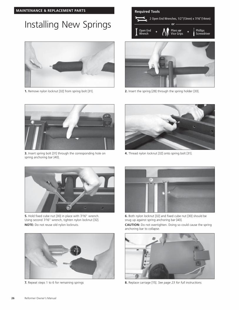
Required Tools
2 Open End Wrenches, 1/2"(13mm) x 7/16"(14mm)
Open End Wrench
Phillips Screwdriver
Pliers or Vice Grips
+ +
or
Reformer Owner’s Manual26
Installing New Springs
3. Insert spring bolt [31] through the corresponding hole on spring anchoring bar [40].
4. Thread nylon locknut [32] onto spring bolt [31].
7. Repeat steps 1 to 6 for remaining springs 8. Replace carriage [15]. See page 23 for full instructions.
6. Both nylon locknut [32] and fixed cube nut [30] should be snug up against spring anchoring bar [40].
CAUTION: Do not overtighten. Doing so could cause the spring anchoring bar to collapse.
5. Hold fixed cube nut [30] in place with 7⁄16" wrench. Using second 7⁄16" wrench, tighten nylon locknut [32].
NOTE: Do not reuse old nylon locknuts.
1. Remove nylon locknut [32] from spring bolt [31]. 2. Insert the spring [28] through the spring holder [33].
MAINTENANCE & REPLACEMENT PARTS Required Tools
2 Open End Wrenches, 1/2"(13mm) x 7/16"(14mm)
Open End Wrench
Phillips Screwdriver
Pliers or Vice Grips
+ +
or
27
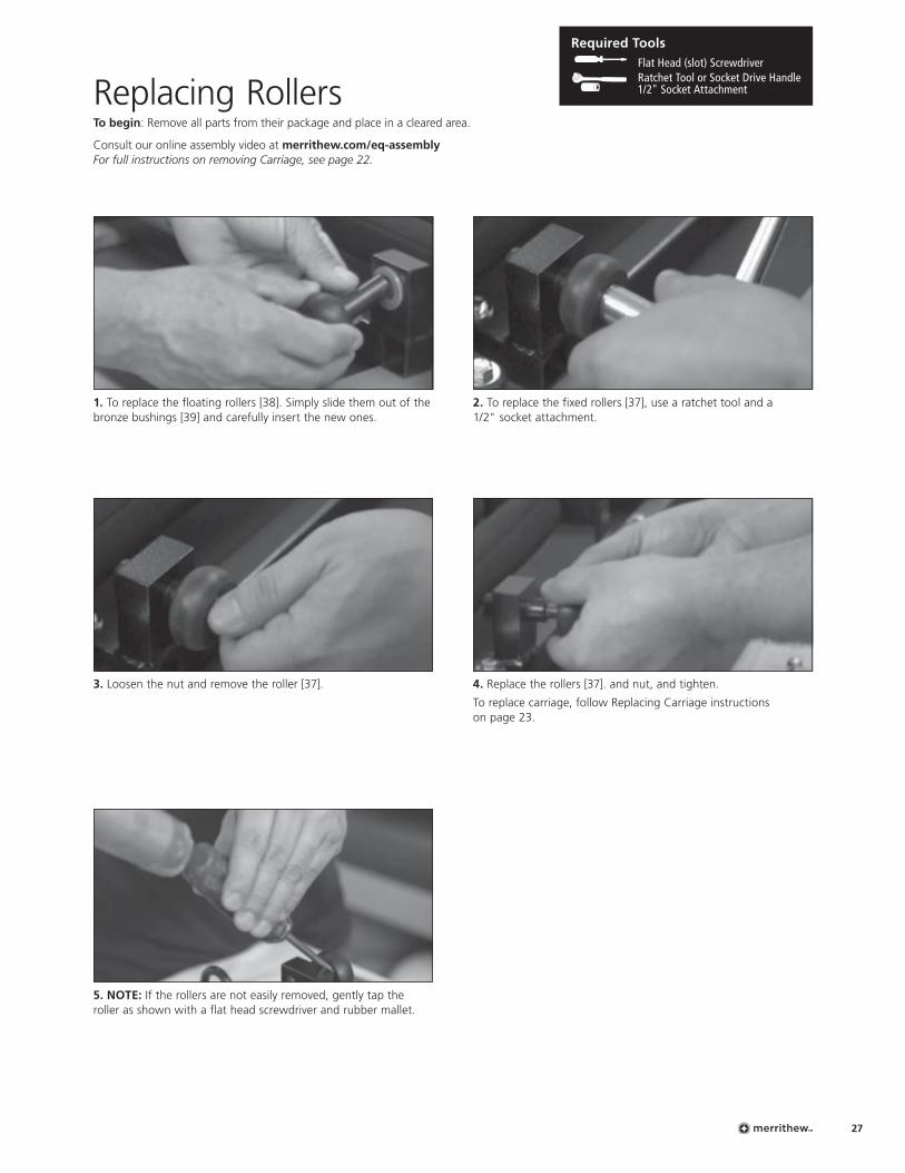
Replacing RollersTo begin: Remove all parts from their package and place in a cleared area.
Consult our online assembly video at merrithew.com/eq-assembly For full instructions on removing Carriage, see page 22.
1. To replace the floating rollers [38]. Simply slide them out of the bronze bushings [39] and carefully insert the new ones.
2. To replace the fixed rollers [37], use a ratchet tool and a 1/2" socket attachment.
4. Replace the rollers [37]. and nut, and tighten.
To replace carriage, follow Replacing Carriage instructions on page 23.
3. Loosen the nut and remove the roller [37].
5. NOTE: If the rollers are not easily removed, gently tap the roller as shown with a flat head screwdriver and rubber mallet.
Required Tools Flat Head (slot) Screwdriver
Ratchet Tool or Socket Drive Handle 1/2" Socket Attachment
Reformer Owner’s Manual28
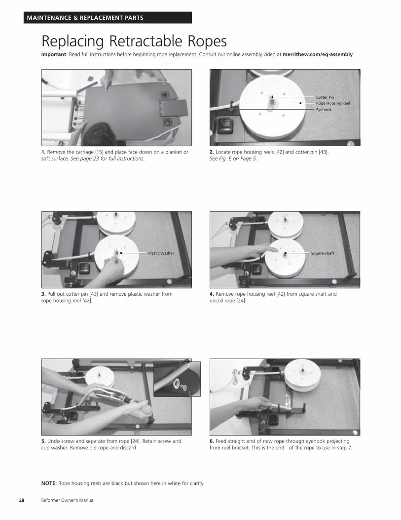
Replacing Retractable RopesImportant: Read full instructions before beginning rope replacement. Consult our online assembly video at merrithew.com/eq-assembly
2. Locate rope housing reels [42] and cotter pin [43]. See Fig. E on Page 5.
3. Pull out cotter pin [43] and remove plastic washer from rope housing reel [42].
5. Undo screw and separate from rope [24]. Retain screw and cup washer. Remove old rope and discard.
4. Remove rope housing reel [42] from square shaft and uncoil rope [24].
6. Feed straight end of new rope through eyehook projecting from reel bracket. This is the end of the rope to use in step 7.
Rope Housing Reel
Eyehook
Plastic Washer
Cotter Pin
1. Remove the carriage [15] and place face down on a blanket or soft surface. See page 23 for full instructions.
Square Shaft
NOTE: Rope housing reels are black but shown here in white for clarity.
MAINTENANCE & REPLACEMENT PARTS
29
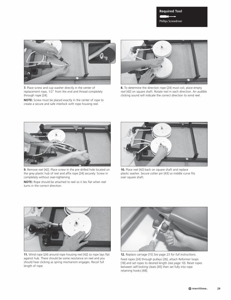
Required Tool
Phillips Screwdriver
7. Place screw and cup washer directly in the center of replacement rope, 1⁄2" from the end and thread completely through rope [24].
NOTE: Screw must be placed exactly in the center of rope to create a secure and safe interlock with rope housing reel.
9. Remove reel [42]. Place screw in the pre-drilled hole located on the grey plastic hub of reel and affix rope [24] securely. Screw in completely without over-tightening.
NOTE: Rope should be attached to reel so it lies flat when reel turns in the correct direction.
11. Wind rope [24] around rope housing reel [42] so rope lays flat against hub. There should be some resistance on reel and you should hear clicking as spring mechanism engages. Recoil full length of rope.
8. To determine the direction rope [24] must coil, place empty reel [42] on square shaft. Rotate reel in each direction. An audible clicking sound will indicate the correct direction to wind reel.
10. Place reel [42] back on square shaft and replace plastic washer. Secure cotter pin [43] so middle curve fits over square shaft.
12. Replace carriage [15] See page 23 for full instructions.
Feed ropes [24] through pulleys [26], attach Reformer loops [18] and set ropes to desired length (see page 10). Reset ropes between self-locking cleats [45] then set fully into rope retaining hooks [48].
Reel Direction
Reformer Owner’s Manual30
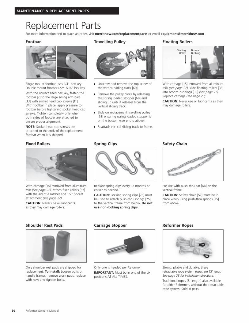
Replacement PartsFor more information and to place an order, visit merrithew.com/replacementparts or email [email protected]
Footbar
Single mount footbar uses 1/4" hex key Double mount footbar uses 3/16" hex key
With the correct sized hex key, fasten the footbar [7] to the large swing arm bars [13] with socket head cap screws [11]. With footbar in place, apply pressure to footbar before tightening socket head cap screws. Tighten completely only when both sides of footbar are attached to ensure proper alignment.
NOTE: Socket head cap screws are attached to the ends of the replacement footbar when it is shipped.
Travelling Pulley
w Unscrew and remove the top screw of the vertical sliding track [60].
w Remove the pulley block by releasing the spring loaded stopper [68] and sliding up until it releases from the vertical sliding track.
w Slide on replacement travelling pulley [58] ensuring spring loaded stopper is on the bottom (see photo above).
w Reattach vertical sliding track to frame.
Floating Rollers
Floating Roller
Bronze Bushing
With carriage [15] removed from aluminum rails (see page 22), slide floating rollers [38] into bronze bushings [39] (see page 27). Replace carriage (see page 23).
CAUTION: Never use oil lubricants as they may damage rollers.
Fixed Rollers
With carriage [15] removed from aluminum rails (see page 22), attach fixed rollers [37] with the aid of a ratchet and 1⁄2" socket attachment (see page 27).
CAUTION: Never use oil lubricants as they may damage rollers.
Spring Clips
Replace spring clips every 12 months or earlier as needed.
CAUTION: Locking spring clips [76] must be used to attach push-thru springs [75]. to the vertical frame from below. Do not use non-locking spring clips.
Safety Chain
For use with push-thru bar [64] on the vertical frame.
CAUTION: Safety chain [57] must be in place when using push-thru springs [75]. from above.
Shoulder Rest Pads
Only shoulder rest pads are shipped for replacement. To install: Loosen bolts on handle frames, remove worn pads, replace with new and tighten bolts.
Carriage Stopper
Only one is needed per Reformer.
IMPORTANT: Must be in one of the six positions AT ALL TIMES.
Reformer Ropes
Strong, pliable and durable, these retractable rope system ropes are 13' length. See page 28 for installation directions.
Traditional ropes (8' length) also available for older Reformers without the retractable rope system. Sold in pairs.
MAINTENANCE & REPLACEMENT PARTS
31
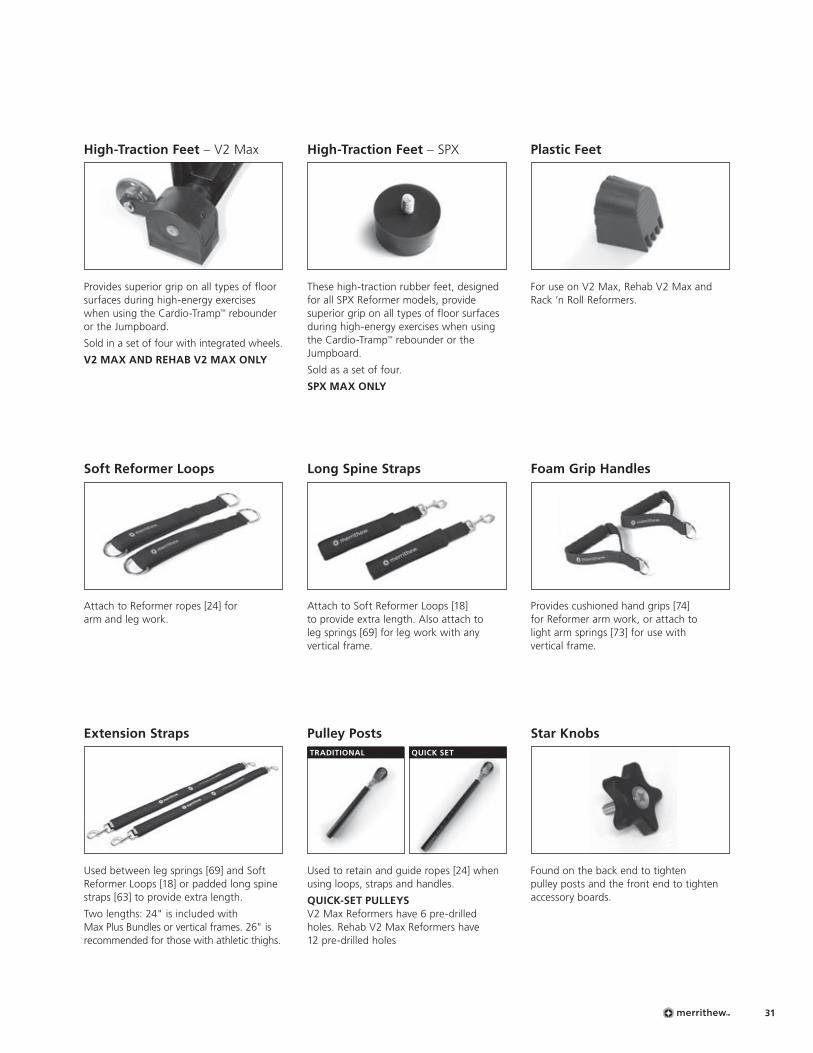
High-Traction Feet – V2 Max
Provides superior grip on all types of floor surfaces during high-energy exercises when using the Cardio-Tramp™ rebounder or the Jumpboard.
Sold in a set of four with integrated wheels.
V2 MAX AND REHAB V2 MAX ONLY
Foam Grip Handles
Provides cushioned hand grips [74] for Reformer arm work, or attach to light arm springs [73] for use with vertical frame.
Long Spine Straps
Attach to Soft Reformer Loops [18] to provide extra length. Also attach to leg springs [69] for leg work with any vertical frame.
Soft Reformer Loops
Attach to Reformer ropes [24] for arm and leg work.
High-Traction Feet – SPX
These high-traction rubber feet, designed for all SPX Reformer models, provide superior grip on all types of floor surfaces during high-energy exercises when using the Cardio-Tramp™ rebounder or the Jumpboard.
Sold as a set of four.
SPX MAX ONLY
Plastic Feet
For use on V2 Max, Rehab V2 Max and Rack ’n Roll Reformers.
Pulley Posts TRADITIONAL QUICK SET
Used to retain and guide ropes [24] when using loops, straps and handles.
QUICK-SET PULLEYS V2 Max Reformers have 6 pre-drilled holes. Rehab V2 Max Reformers have 12 pre-drilled holes
Extension Straps
Used between leg springs [69] and Soft Reformer Loops [18] or padded long spine straps [63] to provide extra length.
Two lengths: 24" is included with Max Plus Bundles or vertical frames. 26" is recommended for those with athletic thighs.
Star Knobs
Found on the back end to tighten pulley posts and the front end to tighten accessory boards.
Reformer Owner’s Manual32
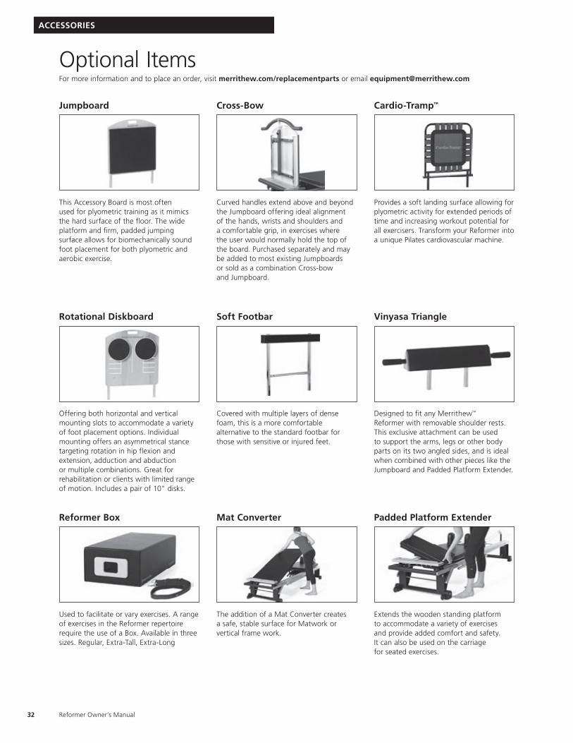
Optional ItemsFor more information and to place an order, visit merrithew.com/replacementparts or email [email protected]
ACCESSORIES
Vinyasa Triangle
Designed to fit any Merrithew™ Reformer with removable shoulder rests. This exclusive attachment can be used to support the arms, legs or other body parts on its two angled sides, and is ideal when combined with other pieces like the Jumpboard and Padded Platform Extender.
Jumpboard
This Accessory Board is most often used for plyometric training as it mimics the hard surface of the floor. The wide platform and firm, padded jumping surface allows for biomechanically sound foot placement for both plyometric and aerobic exercise.
Rotational Diskboard
Offering both horizontal and vertical mounting slots to accommodate a variety of foot placement options. Individual mounting offers an asymmetrical stance targeting rotation in hip flexion and extension, adduction and abduction or multiple combinations. Great for rehabilitation or clients with limited range of motion. Includes a pair of 10" disks.
Cross-Bow
Curved handles extend above and beyond the Jumpboard offering ideal alignment of the hands, wrists and shoulders and a comfortable grip, in exercises where the user would normally hold the top of the board. Purchased separately and may be added to most existing Jumpboards or sold as a combination Cross-bow and Jumpboard.
Soft Footbar
Covered with multiple layers of dense foam, this is a more comfortable alternative to the standard footbar for those with sensitive or injured feet.
Cardio-Tramp™
Provides a soft landing surface allowing for plyometric activity for extended periods of time and increasing workout potential for all exercisers. Transform your Reformer into a unique Pilates cardiovascular machine.
Mat Converter
The addition of a Mat Converter creates a safe, stable surface for Matwork or vertical frame work.
Padded Platform Extender
Extends the wooden standing platform to accommodate a variety of exercises and provide added comfort and safety. It can also be used on the carriage for seated exercises.
Reformer Box
Used to facilitate or vary exercises. A range of exercises in the Reformer repertoire require the use of a Box. Available in three sizes. Regular, Extra-Tall, Extra-Long
33
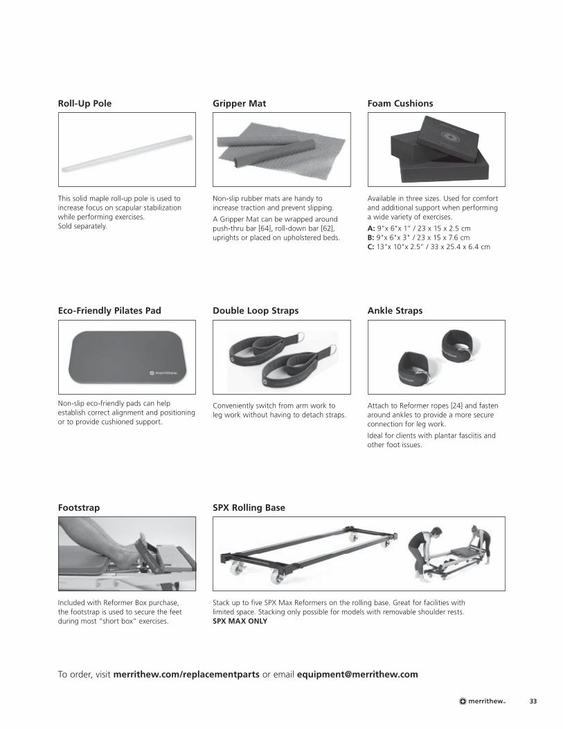
Foam Cushions
Available in three sizes. Used for comfort and additional support when performing a wide variety of exercises.
A: 9"x 6"x 1" / 23 x 15 x 2.5 cm B: 9"x 6"x 3" / 23 x 15 x 7.6 cm C: 13"x 10"x 2.5" / 33 x 25.4 x 6.4 cm
Gripper Mat
Non-slip rubber mats are handy to increase traction and prevent slipping.
A Gripper Mat can be wrapped around push-thru bar [64], roll-down bar [62], uprights or placed on upholstered beds.
Eco-Friendly Pilates Pad
Non-slip eco-friendly pads can help establish correct alignment and positioning or to provide cushioned support.
Roll-Up Pole
This solid maple roll-up pole is used to increase focus on scapular stabilization while performing exercises. Sold separately.
Double Loop Straps
Conveniently switch from arm work to leg work without having to detach straps.
Ankle Straps
Attach to Reformer ropes [24] and fasten around ankles to provide a more secure connection for leg work.
Ideal for clients with plantar fasciitis and other foot issues.
Footstrap
Included with Reformer Box purchase, the footstrap is used to secure the feet during most “short box” exercises.
SPX Rolling Base
Stack up to five SPX Max Reformers on the rolling base. Great for facilities with limited space. Stacking only possible for models with removable shoulder rests. SPX MAX ONLY
To order, visit merrithew.com/replacementparts or email [email protected]
Reformer Owner’s Manual34
THE FINE PRINT
WarrantyMerrithew™ warrants that all new equipment is free of manufacturing defects in workmanship and materials, subject to the terms below. This warranty becomes effective at the invoice date of the original purchase. Parts repaired or replaced under the terms of this warranty will be warranted for the remainder of the original warranty period.
It is the purchaser’s responsibility to notify the Company of any change of contact information. This ensures, that in the unlikely event of a replacement or safety notice, we are able to contact you immediately.
This warranty applies to equipment only:w While it remains in the possession of the original purchaser and proof
of purchase is demonstrated w If claims are made within the part-specific warranty period w If upgrades are made as required by Merrithew
This warranty shall be null and void if:w Equipment failure is a result of improper assembly,
installation or maintenancew The equipment is used for any other purpose other than as
intended, or is stored or used outdoors, or in environments without adequate climate/humidity controls
w Equipment has been subjected to accident, misuse, abuse, improper service, or any modification not authorized by Merrithew
This warranty does not cover damage to the finish of any equipment nor shipping charges, customs clearance fees (if applicable), or any costs incurred in installing repaired or replacement parts shipped under the provisions of this warranty.
Failure to change springs every two (2) years may void warranty.
Limited Lifetime WarrantyMerrithew will, at its option, repair or replace any of the parts listed below, provided that the part(s) fail due to a defect in workmanship or materials and provided such failure occurs and is reported with part-specific warranty period.w Aluminum railsw Components of the frame and related welding w Footbar mechanism (Includes swing arms, chrome adjuster bar
and associated hardware, excludes footbar)
Two (2) Year Limited WarrantyMerrithew will, at its option, repair or replace all other components, including spring holder, springs and High-Traction Reformer Feet that fail for any reason, provided such failure is reported to Merrithew within a period of two years from the invoice date of the original purchase.
One (1) Year Limited WarrantyOn fixed and floating rollers, ropes, straps, spring clips, plastic pulley post receptacle sleeves, comfort footbar, carriage stopper and traditional Reformer feet. We recommend that spring clips (including those attached to traditional-style ropes) be changed annually.
90-Day Upholstery Fabric WarrantyThe vinyl fabric upholstery and spring sleeves will be replaced if they fail to give normal wear for 90 days after delivery. Proof of damage may be required. This warranty does not cover cuts, burns, stains, soiling, pet damage or damage caused by other unreasonable use. This warranty does not apply to fabrics cleaned with abrasive, corrosive or chemical cleansers. If the identical fabric is not available, Merrithew will provide an equivalent.
Disclaimer of Implied Warranties and Limitation of RemediesRepair or replacement of defective parts is your exclusive remedy under the terms of this limited warranty. In the event of parts availability issues, Merrithew will not be responsible for any consequential or incidental damages arising from the breach of either this limited warranty or any applicable implied warranty, or for failure or damage resulting from acts of nature, improper care and maintenance, accident, alteration, replacement of parts by anyone other than Merrithew, misuse, transportation, abuse, hostile environments (inclement weather, acts of nature), improper installation or installation not in accordance with local codes or printed instructions.
This limited warranty is the sole express warranty given by Merrithew. No product performance, specification or description wherever appearing is warranted by Merrithew except to the extent set forth in this limited warranty. Any implied warranty protection arising under the laws of any state, province or territory including implied warranty of merchantability or fitness for a particular purpose, or use, is hereby limited in duration to the duration of this limited warranty.
Neither distributors, dealers, web resellers, nor the retailers selling this product have any authority to make any additional warranties or to promise remedies in addition to, or inconsistent with those stated above. Merrithew’s maximum liability, in any event, shall not exceed the purchase price of the product paid by the original purchaser.
IMPORTANTPlease keep this manual in a safe place. If you have questions, issues or are missing parts:Do NOT return this unit to your local retailer, please contact the manufacturer [email protected] 416.482.4050 | 1.800.910.0001 | 0800.328.5676 UK | ext. 0907
Make the Most of Merrithew™ EquipmentAs Leaders in Mindful Movement™, Merrithew is committed to developing unique, top-quality fitness programs based on the latest in exercise science and research. Our signature STOTT PILATES® education is unparalleled, and we bring the same expertise and passion to our full range of branded programs, including CORE™ Athletic Conditioning and Performance Training™, ZEN·GA®, Total Barre™ and Halo® Training. Join our global community of elite fitness professionals. Merrithew courses and workshops are offered worldwide.
Find courses and workshops near you at merrithew.com/education/training
Contact Us 416.482.4050 | 1.800.910.0001 | 0800.328.5676 UK | ext. 300
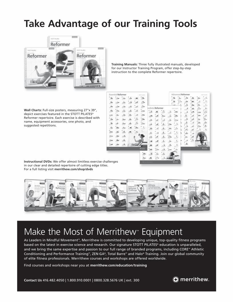
Training Manuals: Three fully illustrated manuals, developed for our Instructor Training Program, offer step-by-step instruction to the complete Reformer repertoire.
Wall Charts: Full-size posters, measuring 27"x 39", depict exercises featured in the STOTT PILATES® Reformer repertoire. Each exercise is described with name, equipment accessories, one photo, and suggested repetitions.
Instructional DVDs: We offer almost limitless exercise challenges in our clear and detailed repertoire of cutting edge titles. For a full listing visit merrithew.com/shop/dvds
Take Advantage of our Training Tools

P0
0179
-01
PM-P
001
79-4
SE
PT17
™
/® T
rade
mar
k or
reg
iste
red
trad
emar
k of
Mer
rith
ew C
orpo
rati
on,
used
und
er li
cens
e. P
rint
ed in
Can
ada.
All
righ
ts
rese
rved
. *U
S Pa
tent
No.
785
7736
, 57
9203
3, 2
1797
93 a
nd o
ther
US
and
fore
ign
pate
nts
pen
ding
.
Please keep this manual in a safe place.
IMPORTANT
This is your Reformer Serial Number:
Go to merrithew.com/warranty to activate your warranty!Get the benefits:w Ensure that you’ll be able to repair it under warranty should you encounter a problem.
w Make warranty service fast and efficient by having your information in our records.
w In the unlikely event of a replacement or safety notice, we’ll be able to contact you immediately.
w Proof of purchase for insurance purposes in the event of a loss due to fire, flood or theft.
w Stay informed of any product updates.
Can’t get online?Please fill out the warranty card enclosed with this product, and return to us.
2200 Yonge Street, Suite 500, Toronto, Ontario, Canada M4S 2C6 416.482.4050 | 1.800.910.0001 | 0800.328.5676 UK | ext. 0907 [email protected] | merrithew.com