reevaluation of holocene faulting at the kaysville site, weber
TRANSCRIPT
TECTONICS, VOL. 13, NO. 1, PAGES 1-16, FEBRUARY 1994
Reevaluation of Holocene faulting at the Kaysville site, Weber segment of the Wasatch fault zone, Utah
James P. McCalpin • Department of Geology, Utah State University, Logan
Steven L. Forman
Byrd Polar Research Center and Department of Geology, Ohio State University, Columbus
Mike Lowe
Utah Geological Survey, Salt Lake City
Abstract. The 1978 Kaysville, Utah, trench excavated by Swan and others (1980) across a large graben of the Weber segment of the Wasatch fault zone was reexcavated in 1988 to reevaluate the timing and nature of Holocene faulting. Relogging of the trench reveals evidence for five or six faulting events younger than the Provo phase of Lake Bonneville (circa 13,000 14C years B.P.). Geometric reconstruction of net vertical offset in the last three events
suggests a variation in coseismic vertical displacement at this site, ranging from a net of 1.4-3.4 m per event. The three latest faulting events occurred at shortly before 0.6-0.8 ka, 2.• 0.7 ka, and circa 3.8-7.9 ka. Earlier events cannot be directly dated because older graben-ffil sediments yielded thermoluminescence ages older than the time of deposition, and some scarp-derived coHuvial wedges beneath the trench floor were not exposed. The two younger faulting events we recognize at Kaysville correlate reasonably well with faulting events on the same segment 25 km north near East Ogden, Utah, at circa 0.8-1.2 ka and 2.5-3.0 ka (Forman and others, 1991), whereas the earlier Kaysville event is significantly older than the earliest (3.5-4.0 ka) event dated at East Ogden. The 3.5-4.0 ka ground rupture recognized at East Ogden may have died out at a subsegment boundary between the two trench sites within the 61-kin-long Weber segment.
INTRODUCTION
The Wasatch fault zone (WFZ) was a target of early palcoseismological research utilizing trench exposures to describe the sedimentologic record of normal fault displacements and to date Holocene faulting events. One of the earliest excavations (1978) near Kaysville, Utah, on the
t Now at: GEO-HAZ Consulting, Incorporated, Estes Park, Colorado.
Copyright 1994 by the American Geophysical Union.
Paper number 93TC02067. 0278-7407/94/93TC02067510.00
Weber segment of the WFZ (as defined by Machette et al, [1991, 1992]) revealed compelling evidence for multiple surface faulting events during the Holocene [Swan et al., 1980, 1981]. Two concepts developed from interpretations of this trench later became part of the foundation of modern paleoseismology. The first concept is that individual palcoseismic ruptures are often recorded by discrete wedge- shaped deposits of scarp-derived coHuvium [Hanson and Schwartz, 1982]. The second concept is that faults (or fault segments) rupture during large earthquakes within a characteristic magnitude range ("characteristic earthquakes" [Schwartz and Coppersmith, 1984]). Despite these important concepts generated by the early palcoseismic research, the chronology of palcoseismic events at Kaysville was poorly constrained by a single radiocarbon age from outside the main fault zone penetrated by the 1978 excavation.
Several improved palcoseismic techniques, developed on the WFZ and other faults in the past decade, were applied to the KaysviHe site in this study. Radiocarbon dating of soil horizons with a low organic carbon content, using conventional or accelerator mass spectroscopy (AMS) techniques, has been successful in reconstructing Holocene faulting chronologies elsewhere on the WFZ (summarized by Machette et al. [1991, 1992]). Thermoluminescence dating, used in conjunction with 14C dating, has provided additional constraints on faulting for the WFZ [Forman et al., 1989, 1991). In addition, recent work on the sedimentation patterns in normal fault zones [Nelson, 1992; McCalpin et al., 1993] and on geometry of normal surface ruptures [McCalpin, 1983, 1987] were used to refine the faulting chronology originally proposed by Swan et al. [1980].
The Kaysville site was attractive because previous trenching [Swan et al., 1981] had documented a thick, fine- grained graben fill that might yield additional 14C and TL age constraints on Holocene faulting. Our new data on fault timing and displacement add to recent mapping [Nelson and Personius, 1990, in press] and geochronologic work [Nelson, 1988; Forman et al., 1991; Macbette et al., 1992] from two trench sites farther north on the Weber segment, which at 61 km long is the second-longest segment of the WFZ. In particular, we attempt to correlate the three latest Holocene
2 McCalpin et al.: Holocene Faulting in Utah
ruptures at Kaysville with those dated at sites 25 km farther north on the same segment [Forman et al., 1991].
GEOMORPHIC SETTING
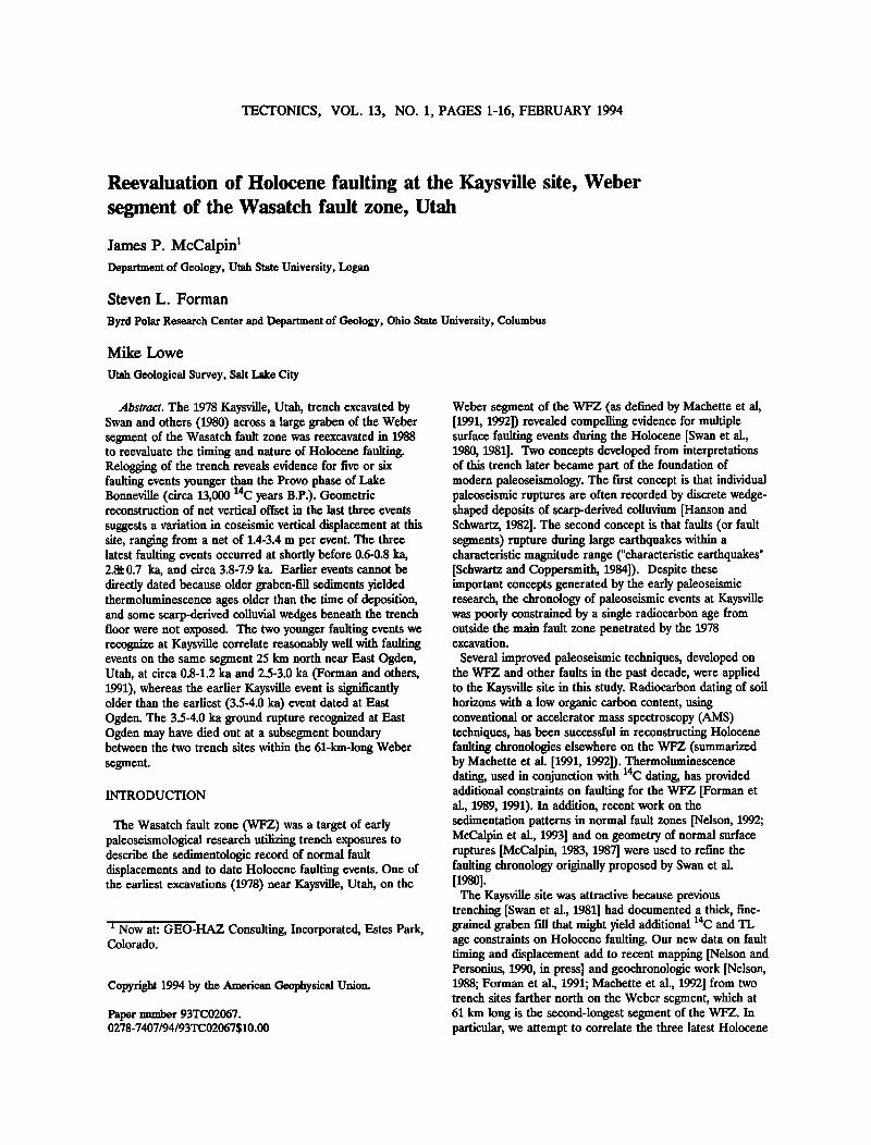
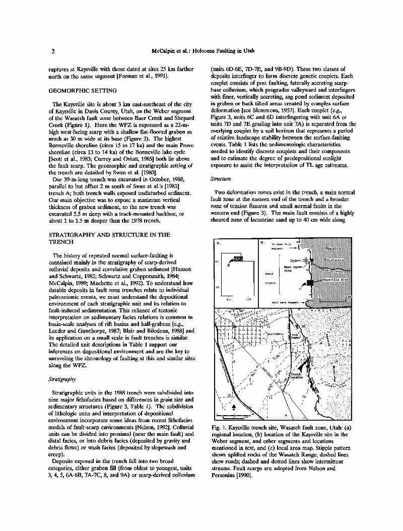
The Kaysville site is about 3 km east-southeast of the city of Kaysville in Davis County, Utah, on the Weber segment of the Wasatch fault zone between Baer Creek and Shepard Creek (Figure 1). Here the WFZ is expressed as a 22-m- high west-facing scarp with a shallow flat-floored graben as much as 30 m wide at its base (Figure 2). The highest Bonneville shoreline (circa 15 to 17 ka) and the main Provo shoreline (circa 13 to 14 ka) of the Bonneville lake cycle [Scott et al., 1983; Curmy and Oviatt, 1985] both lie above the fault scarp. The geomorphic and stratigraphic setting of the trench are detailed by Swan et al. [1980].
Our 39-m-long trench was excavated in October, 1988, parallel to but offset 2 m south of Swan et al.'s [1981] trench A; both trench walls exposed undisturbed sediment. Our main objective was to expose a maximum vertical thickness of graben sediment, so the new trench was excavated 5.5 m deep with a track-mounted backhoe, or about 1 to 1.5 m deeper than the 1978 trench.
STRATIGRAPHY AND STRUCTURE IN THE
TRENCH
The history of repeated normal surface-faulting is contained mainly in the stratigraphy of scarp-derived colluvial deposits and correlative graben sediment [Hanson and Schwartz, 1982; Schwartz and Coppersmith, 1984; McCalpin, 1989; Machette et al., 1992). To understand how datable deposits in fault zone trenches relate to individual paleoseismic events, we must understand the depositional environment of each stratigraphic unit and its relation to fault-induced sedimentation. This reliance of tectonic
interpretation on sedimentary facies relations is common in basin-scale analyses of rift basins and half-grabens [e.g., Leeder and Gawthorpe, 1987; Blair and Bilodeau, 1988] and its application on a small scale in fault trenches is similar. The detailed unit descriptions in Table i support our inferences on depositional environment and are the key to unraveling the chronology of faulting at this and similar sites along the WFZ.
Stratigraphy
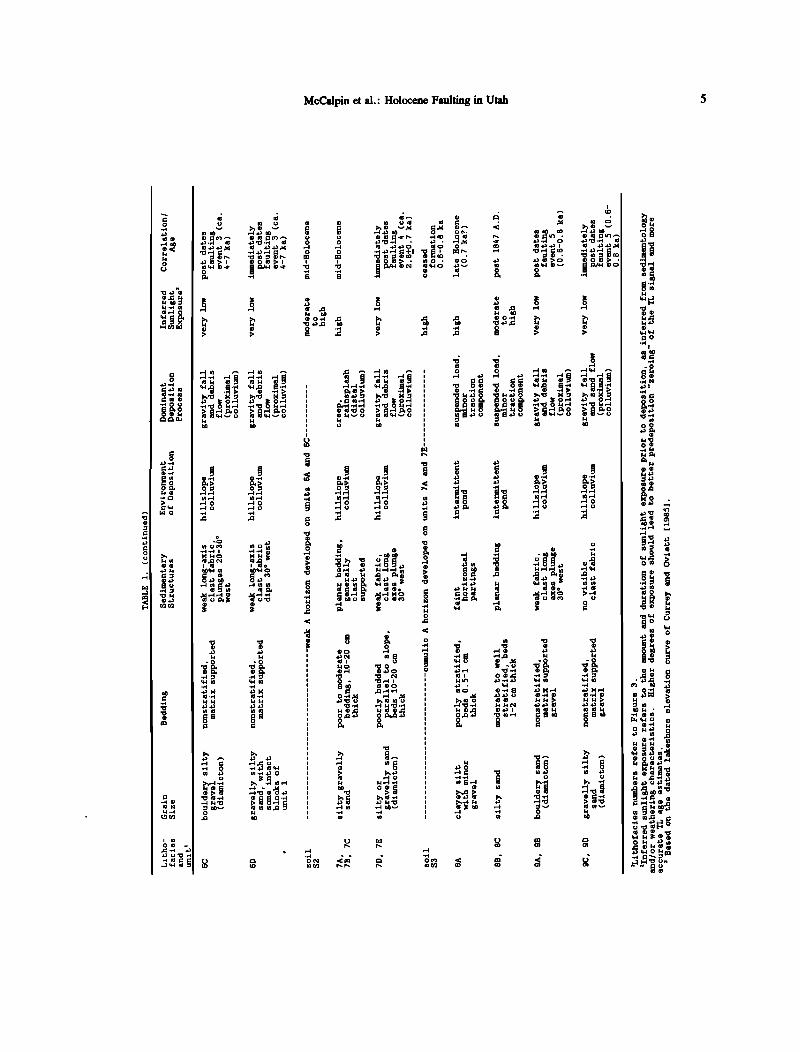
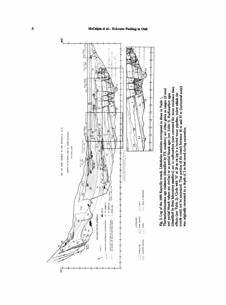
Stratigraphic units in the 1988 trench were subdivided into nine major lithofacies based on differences in grain size and sedimentary structures (Figure 3, Table 1). The subdivision of lithologic units and interpretation of depositional environment incorporate some ideas from recent lithofacies models of fault-scarp environments [Nelson, 1992]. Colluvial units can be divided into proximal (near the main fault) and distal facies, or into debris facies (deposited by gravity and debris flows) or wash facies (deposited by slopewash and creep).
Deposits exposed in the trench fall into two broad categories, either graben fill (from oldest to youngest, units 3, 4, 5, 6A-6B, 7A-7C, 8, and 9A) or scarp-derived colluvium
(units 6D-6E, 7D-7E, and 9B-9D). These two classes of deposits interf'mger to form discrete genetic couplets. Each couplet consists of post faulting, laterally accreting scarp- base colluvium, which progrades valleyward and interfmgers with freer, vertically accreting, sag pond sediment deposited in graben or back tilted areas created by complex surface deformation [see Slemmons, 1957]. Each couplet (e.g., Figure 3, units 6C and 6D interfingering with unit 6A or units 7D and 7E grading into unit 7A) is separated from the overlying couplet by a soil horizon that represents a period of relative landscape stability between the surface-faulting events. Table 1 lists the sedimentologic characteristics needed to identify discrete couplets and their components and to estimate the degree of predepositional sunlight exposure to assist the interpretation of TL age estimates.
Structure
Two deformation zones exist in the trench, a main normal fault zone at the eastern end of the trench and a broader zone of tension fissures and small normal faults in the
western end (Figure 3). The main fault consists of a highly sheared zone of lacustrine sand up to 40 cm wide along
Fig. 1. Kaysville trench site, Wasatch fault zone, Utah: (a) regional location, (b) location of the Kaysville site in the Weber segment, and other segments and locations mentioned in text, and (c) local area map. Stipple pattern shows uplifted rocks of the Wasatch Range; dashed lines show roads; dashed and dotted lines show intermittent streams. Fault scarps are adopted from Nelson and Personius [1990].
McCalpin et al.' Holocene Faulting in Utah 3
.... •-. ,• .... ..•.:•':5.. ß ...... :-.. (-:•:.. . ..... .•,. .•'• .:•....•,..::.,• .:,•..• • ..... ':•. •..:•;;.. ,.•:;,: ':;•.,.,.:;j•:;;. .......... :.:,.•;? .,•1•,,:•.: .... :.:......•..?.,:..•.• ....................... :•:.:...•:;.•?;•:•½½•:;•:.,.:•. :'•.:•,,,•...• ........ ;:?;'":".':"'"½•":"•n . •.. -"'-' ' ..... :;.--'½:•(4::":• ' ..... •:•; :•'--'•.'•.•:,.,•. ;( .......... --- , • . . '--':-.•:•.:;::.,-';.' ,......:......:... ;;':.':• •:•..:.• .--. ...... .:.:::R.-•;:..,?:• • • -. : '•.,';-.:-,,•.... • •... . .-;.' .,::.;•::,::..:.;:...... ....... :::,,:.,.... -•
'- • ':•:...'....::'- ......... --,,. "::' .,,.•... •:;..;.'?:--,:'".',:•...;j:;:•!..:,..-:::, • • .. ";¾..:.... .... ;' -,.=..,...•..;.,• . ..
.... '*'"•'1;' :•i ' ';" • .
,..• •,•, ,. . . .•. • ..k..
•..
.: -. ... .
;..•.. .... , -;-... ... . : .... ;: ß .• . .... ;..
e •,• ',•;:•::'-;;,,.:RX:;:.......:; ............... ß ..... :......'::'"•;;.,-•..-,,.,•.' ......... '*-;•;,.::..-; ..... ß .......... :i "• "•"•*'• .... '"•'"•""•'••*•"•'•••••'•;'::•";d½•:•;'•'•:"•(:•"-':• '""'"•
.... ,,.,,.:..,:.: ::... ..... .::
Fig. 2. Photograph of the Kaysville fault scarp and trench, looking east. Scarp height at left center (shadowed) is 22 m; width of graben in foreground is 30 m. The gully to the right of the trench is a local source of sediment for the graben. Note large alluvial fan at mouth of gully. Much of the fan was deposited historically and grades into graben fill unit 8B (Figure 3). The sparsely vegetated slope above the fault scarp in the background is bounded by the Bonneville highstand shoreline (upper boundary) and the Provo shoreline (lower boundary).
which most Holocene displacement has presumably occurred. The fault strikes N00ø-09øE and dips 680-70 ø W. High-resolution seismic-reflection surveys [Stephenson et al., 1993] suggest the fault dip decreases to 45 ø at 25 m depth. The 25 ø steepening of the main fault dip near the surface, which is typical of normal faults, results in creation of void space during each faulting event and provides space into which graben deposits are backtilted or downdropped.
A fissure zone extends from 11 m on the trench log (Figure 3) to beyond the western end of the trench. According to the log of Swan et al. [1980] another 9 m of faulted and fissured graben fill extends west beyond our trench to a major antithetic fault zone, which defines the western edge of the present topographic graben. The densely fissured area (Figure 3, 5-6 m on horizontal scale) corresponds to a tilt "hingeline" separating faulted but nearly horizontal graben deposits (to the west) from progressively east-tilted, relatively unfaulted graben deposits to the east. This Holocene hingeline is different from the older hingeline defined by Swan et al. [1980, their Figure 4] about 60 m west of the main fault, which affects only lithofacies 2.
Two kinds of structures exist in the fissure zone, small- displacement normal faults and open tension fissures filled with organic soil material. The small-displacement faults form a zone of dosely spaced (0.5-2.0 m), conjugate normal faults that dip 60øW and 80øE, respectively. Conjugate faults are mainly developed in the moist, massive silt of lithofacies 3. This cohesive unit probably responded to east- west stretching over the Holocene tilt hingeline by conjugate shear, whereas the overlying gravelly units may have extended by developing vertical tension fissures more suggestive of dry, brittle fracture. The fissures are filled with friable, organic-rich, dark brown, stone-free silt and sand
that is similar to the overlying soil (S3). We interpret the fissure-filling material as surface A horizon material that fell into open fractures from soil S3 after a faulting event.
Between the main fault zone and the fissure zone, the trench exposed an east-tilted, unfaulted block of Holocene graben-fill sediment. The eastward dip of beds in the sequence steepens with increasing depth, indicating greater tilt of the older beds (Figure 3). The differences between the dip of beds provide one basis for reconstructing the timing of faulting (discussed later). The eastward dip of individual beds also increases toward the main fault zone.
Projection of the Provo alluvial fan/graben fdl contact (the lithofacies 2B/3a contact) to the main fault zone suggests that the graben fill may reach a thickness of 11 m at the main fault.
GEOCHRONOLOGY
Radiocarbon Dating
One way to constrain the timing of fault events is to date organic material from A horizons of paleosols that were buried by colluvium shed from a fault scarp [Schwartz and Coppersmith, 1984; Nelson and Van Arsdale, 1986; Forman et al., 1989, 1991; Machette et al., 1992]. Fortunately, two buried paleosols (S1 and S3) with well-preserved A horizons occur in the graben sediment. The upper 10 cm of the A horizons of soils S1 and S3 were sampled for conventional radiocarbon dating (Table 2). The < 125 um fraction of these samples was isolated and organic matter concentrated following the procedure of Kihl [1975]. An estimated mean residence time (MRT) of 30• 200 years was subtracted from all laboratory inc ages (Table 2), following the

4 McCalpin et al.' Holocene Faulting in Utah
ß ,--I
0.,•
O0
q-• I
•) 0 .
4J 0•)
McCalpin et al.: Holocene Faulting in Utah
ocq
6 McCalpin et al.' Holocene Faulting in Utah
I I I I I

McCalpin et at.' Holocene Faulting in Utah 7
o o o
o o •D
0
0 0 •D
0
0 0
procedure of Machette et at. [1992, Appendix]. These ages were then calendar-corrected using the method of Stuiver and Reimer [1986].
Thermoluminescence Dating
A relatively new technique to constrain the timing of faulting events is thermoluminescence dating [McCalpin, 1986; Forman et al., 1989, 1991; McCalpin and Forman, 1991]. Exposure of mineral grains to ionizing radiation after burial causes mineral lattice damage that results in luminescence upon heating. Sediment that receives prolonged light exposure prior to deposition, for example loess and A horizons of soils, is particularly suitable for TL dating. Water-lain sediment, particularly fluvial sediment, often yields overestimates in age because of insufficient light exposure prior to deposition [Forman, 1989]. The 4/•m-ll /• m (silt) fraction was isolated for TL analyses following the procedures outlined by Forman et al. [1989, 1991]. All samples were analyzed by the total- and partial-bleach techniques, assuming a mean water content of 15ø/• 5% (Table 3). For a broader overview of TL dating applied to Quaternary deposits, the reader is referred to Forman [1989] and Forman and Machette [1991].
Ages of Trench Soils and Deposits
Both soil A horizons and fluvial/lacustrine sediments were sampled for thermoluminescence dating. The general accuracy of TL age estimates is evaluated by comparison to radiocarbon ages on soils S1 and S3, which yielded 14C ages of circa 6.• 0.3 ka and 0.6-0.• 0.2 ka, respectively. One sample from the A horizon of soil 3 yielded TL ages of 0.• 0.2 ka and 0.• 0.1 ka by the partial- and total-bleach techniques, respectively, which is in good agreement with the radiocarbon ages. The four numerical ages from the upper 10 cm of soil S3 and the one age from unit 8A provide limits on the time of burial of soil S3 by renewed sag pond deposition. In the western part of the graben (Figure 3, samples ITL 149, Beta-29901), soil S3 was buried at a mean age of 81• 287 years B.P. In contrast, numerical ages from the top of soil S3 at the toe of the fault scarp (Figure 3, 20 m on horizontal scale) indicate burial occurred after 65• 344 years B.P. (mean age of samples ITL 151 and Beta-29902) and before 60• 100 yr (ITL 169). This 200- year age discrepancy could be explained if unit 8A initially buried soil S3 in a topographic low in the western part of the graben at about 815 years B.P., and slowly accreted laterally and vertically, burying soil S3 at the toe of the scarp (at a slightly higher elevation) some 200 years later.
The inception of soil S3 formation can be estimated based on its surface age and accumulation rates of cumulic soils dated elsewhere by closely spaced vertical TL and dating. Forman et al. [1991] and Warren and McCalpin [1992] suggest that at distances of 5-10 m from the main fault, cumulic A horizons on wash facies colluvium (in semi arid climates with sagebrush vegetation) accumulate at rates of about • 1 cm/100 yr between faulting events. The 63-

8 McCalpin et al.: Holocene Faulting in Utah
TABLE 3. Equivalent Doses and TL Age Estimates for Sediments from the 1988 Kaysville Trench, Weber Segment, Wasatch Fault Zone.
Laboratory Depositional Temperature Equivalent TL Age Number Environment Method1 Range, (øC)Z Dose, (Gy) 3Estimate, (ka)4
ITL-149 buried soil A horizon regeneration 16 hour SL 250-350 9.79 + 3.19 1.6 + 0.2 total bleach 16 hour SL 250-350 10.27 _+ 1.82 1.6 _+ O.Z total bleach 8 h UV 250-350 10.29 + 1.01 1.6 _+ O.Z
partial bleach Z hour SL 250-320 524 + 1.1 8 0.8 + O.Z I%-150 buried soil A horizon total bleach 16 hour SL 250-350 40.28 + 4.84 6.5 + 0.7
total bleach 8 h UV 250-350 42.20 + 4.05 6.8 + 0.7
partial bleach 2 hour SL 250-330 43.33 + 5.26 7.0 + 0.9 ITL-151 buried soil A horizon total bleach 16 hour SL 250-400 4.37 + 0.45 0.8 + 0.1
partial bleach 1 hour SL 250-400 3.95 + 0.95 0.7 + 0.2 total bleach 16 hour SL 250-350 104.60 + 12.85 14.3 + 2.0
partial bleach Z hour SL 250-320 10Z.6Z + 14.44 14.0 + 2.0 ITL-153 fluvial/lacustrine total bleach 16 hour SL 250-350 161.22 + 27.6 28 + 5
partial bleach Z hour SL 250-320 203.38 + 41.3 35 + 7 ITL-168 fluvial/lacustrine total bleach 16 hour SL 250-350 92.71 + 8.34 16 + 2
partial bleach Z hour SL 250-320 97.74 + 13.14 17 + 3 partial bleach 10 hour SL/OF 250-320 122.60 + 18.82 22 _+ 3 partial bleach 14 hour UV/OF 250-320 107.00 + 19.76 19 + 3
ITL-169 shallow lacustrine total bleach 16 hour $L 250-370 9.55 + 0.87 1.2 + 0.2
partial bleach 1 hour SL 250-320 4.32 + 0.90 0.6 + 0.1 ITL-170 shallow lacustrine total bleach 16 hour SL 250-350 1 3.68 + 0.96 2.0 + 0.2
partial bleach Z hour SL 250-350 13.12 + 1.43 1.9 + O.Z ITL-171 buried soil A horizon total bleach 16 hour SL 250-350 30.78 + 4.64 5.0 + 0.7
partial bleach 2 hour SL 250-350 29.27 + 6.95 4.7 + 0.9 ITL-172 fluvial/lacustrine total bleach 16 hour SL 250-350 158.20 + 20.51 24 + 4
partial bleach Z hour SL 250-350 207.41 + 31.62 32 + 5
1Hours of light exposure to define residual level. SL is natural sunlight in Boulder, Colorado. UV is light from a "General Electric" 275 W ultraviolet sunlamp bulb. OF is a light exposure with wavelengths below 540 nm blocked (<1% transmission) with a Corning CS3-67 glass filter.
ZAII thermoluminescence measurements were made with a Schott UG-1 land HA-3 filters in front of the
photomultiplier tube. Samples were preheated to 150 ø C for16 hours pdor to analysis. All samples exhibited negligible anomalous fading, within analytical resolution of + 10%.
3Temperature range used to calculate equivalent dose. 4 All errors are at lo and calculated by averaging the errors across the temperature range.
cm-thick soil S3 may thus represent about 210(3:630 years of soil formation, which ended by circa 600-800 years B.P. Soil S3 may thus have begun forming by 280(3:730 yr BP (mean value of the above ages). This age range is compatible with older TL and InC age estimates for underlying soil S1 (discussed next) and with an age of 1870 + 269/-320 years B.P. on fissure-fill derived from soil S3 (Figure 3 and Table 2, sample Beta-38680).
The fissures displace all units except the youngest colluvial-graben fill couplet, indicating that they opened (due to hingeline "stretching"?) during the latest faulting event. Deposition of 8A is dated at ca. 600-800 years B.P., whereas the material at the bottom of the fissure dates at 1870
+ 269/-320 years B.P. If this basal fissure fill material fell from soil S3 during latest faulting (shortly before 600-800 years B.P.), why does it carry a Inc age of circa 1900 years B.P.? The simplest explanation is that at the time of faulting, a thick vertical slice of soil S3 fell more-or-less
intact into the fissure. The material that came to rest in the
bottom of the crack was actually derived from the lower part of soil S3, which had begun forming by circa 2.8 ka.
Concordancy between radiocarbon and TL age estimates was also obtained for buried soil S1. Sample ITL 150 from the A horizon of soil ! yielded TL ages of 6.• 0.7 ka and 6.• 0.7 ka (total bleach), and 7.• 0.9 ka (partial bleach), all of which are in good agreement with the radiocarbon age of 6.• 0.3 ka. A second sample from the A horizon of soil ! yielded somewhat younger TL ages of 5.• 0.7 ka and 4.• 0.7 ka by the total and partial bleach methods, respectively. The TL age and 14C estimates indicate that soil ! was buried by fault scarp colluvium sometime between 3.8 ka and 7.9 ka (one-sigma age range); at two sigma, all six limiting age estimates overlap in the range 5.7-6.1 ka.
The sag pond and fluvial sediment yielded TL age estimates that are often 3 to 8 times older than the
concordant TL and 14C ages on adjacent buried soils. The
McCalpin et al.: Holocene Faulting in Utah 9
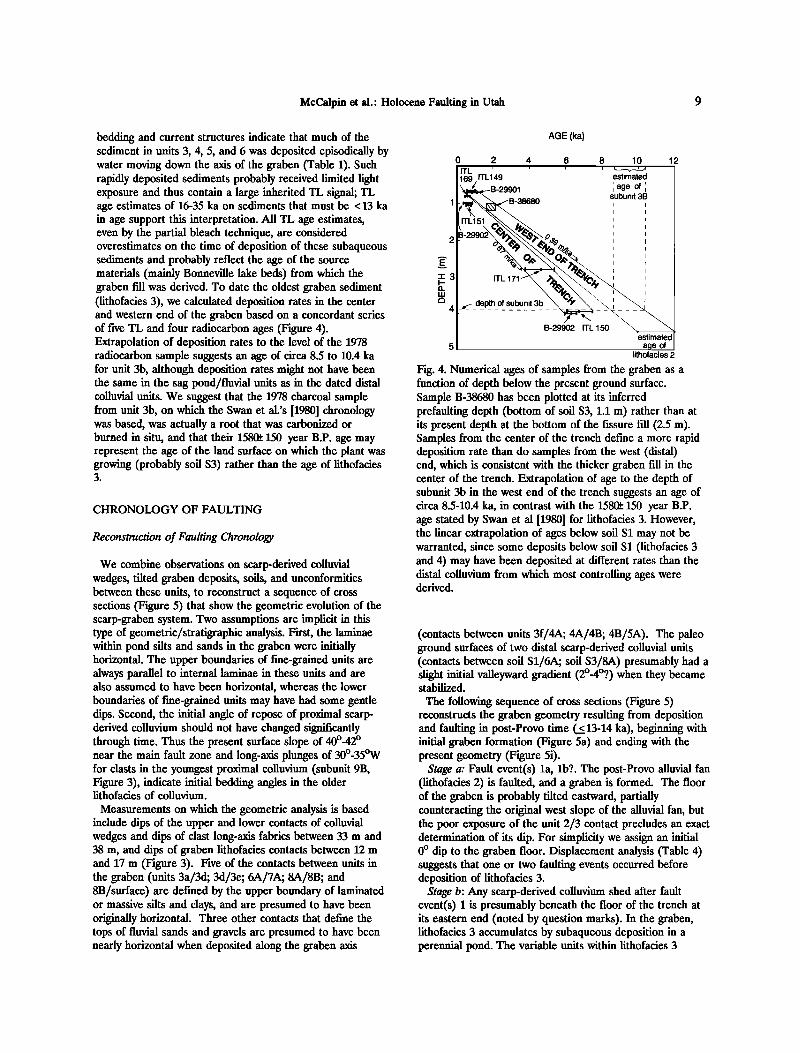
bedding and current structures indicate that much of the sediment in units 3, 4, 5, and 6 was deposited episodically by water moving down the axis of the graben (Table 1). Such rapidly deposited sediments probably received limited light exposure and thus contain a large inherited TL signal; TL age estimates of 16-35 ka on sediments that must be < 13 ka in age support this interpretation. All TL age estimates, even by the partial bleach technique, are considered overestimates on the time of deposition of these subaqueous sediments and probably reflect the age of the source materials (mainly Bonneville lake beds) from which the graben fill was derived. To date the oldest graben sediment (lithofacies 3), we calculated deposition rates in the center and western end of the graben based on a concordant series of five TL and four radiocarbon ages (Figure 4). Extrapolation of deposition rates to the level of the 1978 radiocarbon sample suggests an age of circa 8.5 to 10.4 ka for unit 3b, although deposition rates might not have been the same in the sag pond/fluvial units as in the dated distal colluvial units. We suggest that the 1978 charcoal sample from unit 3b, on which the Swan et al.'s [1980] chronology was based, was actually a root that was carbonized or burned in situ, and that their 158• 150 year B.P. age may represent the age of the land surface on which the plant was growing (probably soil S3) rather than the age of lithofacies 3.
CHRONOLOGY OF FAULTING
Reconstruction of Faulting Chronology
We combine observations on scarp-derived colluvial wedges, tilted graben deposits, soils, and unconformities between these units, to reconstruct a sequence of cross sections (Figure 5) that show the geometric evolution of the scarp-graben system. Two assumptions are implicit in this type of geometric/stratigraphic analysis. First, the laminae within pond silts and sands in the graben were initially horizontal. The upper boundaries of fine-grained units are always parallel to internal laminae in these units and are also assumed to have been horizontal, whereas the lower boundaries of fine-grained units may have had some gentle dips. Second, the initial angle of repose of proximal scarp- derived colluvium should not have changed significantly through time. Thus the present surface slope of 400-42 ø near the main fault zone and long-axis plunges of 30ø-35øW for clasts in the youngest proximal colluvium (subunit 9B, Figure 3), indicate initial bedding angles in the older lithofacies of colluvium.
Measurements on which the geometric analysis is based include dips of the upper and lower contacts of colluvial wedges and dips of clast long-axis fabrics between 33 m and 38 m, and dips of graben lithofacies contacts between 12 m and 17 m (Figure 3). Five of the contacts between units in the graben (units 3a/3d; 3d/3e; 6A/7A; 8A/8B; and 8B/surface) are defined by the upper boundary of laminated or massive silts and clays, and are presumed to have been originally horizontal. Three other contacts that define the tops of fluvial sands and gravels are presumed to have been nearly horizontal when deposited along the graben axis
AGE (ka)
0 2 4 6 8 10 12 m_ .... 169 ITL149 estimated
k•• B_29901 ;age of 1 •.••[••-38680 subunit 3B
r• depth of subunit 3b •O•,,__•".. % 4 *•
B-29902 ITL 150 -., estimated
5 aqe of J lithofacies 2
Fig. 4. Numerical ages of samples from the graben as a function of depth below the present ground surface. Sample ]3-38680 has been plotted at its i•erred prefaulting depth (bottom of soil $3, 1.1 m) rather than at its present depth at the bottom of the fissure fill (2.5 m). Samples from the center of the trench define a more rapid deposition rate than do samples from the west (distal) end, which is consistent with the thicker graben fill in the center of the trench. Extrapolation of age to the depth of subunit 3b in the west end of the trench suggests an age of circa 8.5-10.4 ka, in contrast with the 158• 150 year B.P. age stated by Swan et al [1980] for lithofacies 3. However, the linear extrapolation of ages below soil S! may not be warranted, since some deposits below soil S! (lithofacies 3 and 4) may have been deposited at different rates than the distal colluvium from which most controlling ages were derived.
(contacts between units 3f/4A; 4A/4B; 4B/5A). The paleo ground surfaces of two distal scarp-derived colluvial units (contacts between soil S1/6A; soil S3/8A) presumably had a slight initial valleyward gradient (2ø-4ø?) when they became stabilized.
The following sequence of cross sections (Figure 5) reconstructs the graben geometry resulting from deposition and faulting in post-Provo time (_5_ 13-14 ka), beginning with initial graben formation (Figure 5a) and ending with the present geometry (Figure 5i).
Stage a: Fault event(s) la, lb?. The post-Provo alluvial fan (lithofacies 2) is faulted, and a graben is formed. The floor of the graben is probably tilted eastward, partially counteracting the original west slope of the alluvial fan, but the poor exposure of the unit 2/3 contact precludes an exact determination of its dip. For simplicity we assign an initial 0 ø dip to the graben floor. Displacement analysis (Table 4) suggests that one or two faulting events occurred before deposition of lithofacies 3.
Stage b: Any scarp-derived colluvium shed after fault event(s) ! is presumably beneath the floor of the trench at its eastern end (noted by question marks). In the graben, lithofacies 3 accumulates by subaqueous deposition in a perennial pond. The variable units within lithofacies 3
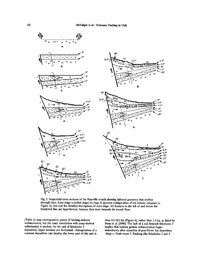
10 McCalpin et al.' Holocene Faulting in Utah
a.
• Oø 1 -- • ...... 3 •/-0ø
b.
0 o
o
320
• +3'5 o l\
d.
32.5
40 o
S2 17.5 ø
42 o
38 ½
35 o
6D+E _
S3 • S2
1 o
o 2
0 0
-4.5 o
_10 o
3 •'
÷2 0
Fig. 5. Sequential cross sections of the Kaysville trench showing inferred geometry that evolves through time, from stage a (initial stage) to stage h (present configuration of the trench; compare to Figure 3). See text for detailed descriptions of each stage. All features to the left of and below the bracketed line are hypothetical, because they were beneath the trench floor.
(Table 1) may correspond to pulses of faulting-induced sedimentation, but the exact correlation with scarp-derived colluvium(s) is unclear. At the end of lithofacies 3 deposition, upper laminae are horizontal. Extrapolation of a constant deposition rate implies the lower part of this unit is
circa 8.5-10.2 ka (Figure 4), rather than 1.5 ka, as dated by Swan et al. [1980]. The lack of a soil beneath lithofacies 3 implies that earliest graben sedimentation began immediately after cessation of post-Provo fan deposition. Stage c: Fault event 2. Faulting tilts lithofacies 2 and 3
McCalpin et al.: Holocene Faulting in Utah 11
UPTHROWN T•-I TM I ...... 1
MAIN FAULT ANTITHETIC
FAULT
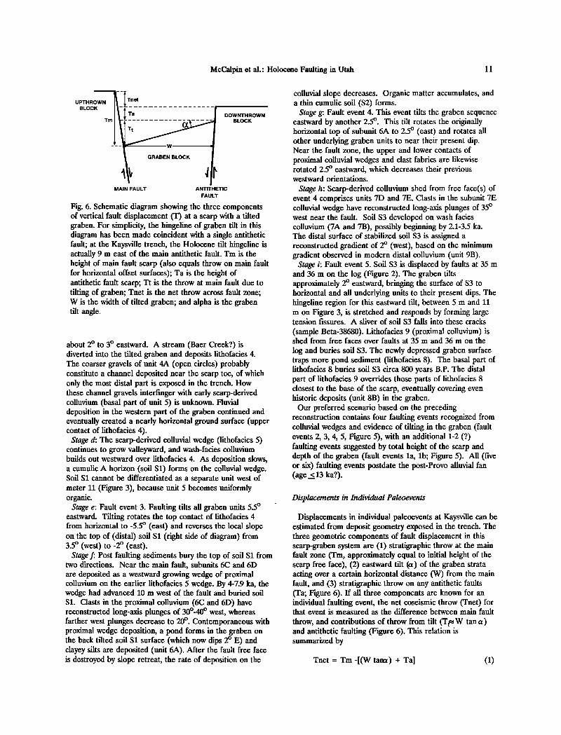
Fig. 6. Schematic diagram showing the three components of vertical fault displacement (T) at a scarp with a tilted graben. For simplicity, the hingeline of graben tilt in this diagram has been made coincident with a single antithetic fault; at the Kaysville trench, the Holocene tilt hingeline is actually 9 m east of the main antithetic fault. Tm is the height of main fault scarp (also equals throw on main fault for horizontal offset surfaces); Ta is the height of antithetic fault scarp; Tt is the throw at main fault due to tilting of graben; Tnet is the net throw across fault zone; W is the width of tilted graben; and alpha is the graben tilt angle.
about 2 ø to 3 ø eastward. A stream (Baer Creek?) is diverted into the tilted graben and deposits lithofacies 4. The coarser gravels of unit 4A (open circles) probably constitute a channel deposited near the scarp toe, of which only the most distal part is exposed in the trench. How these channel gravels interfinger with early scarp-derived colluvium (basal part of unit 5) is unknown. Fluvial deposition in the western part of the graben continued and eventually created a nearly horizontal ground surface (upper contact of lithofacies 4).
Stage d: The scarp-derived colluvial wedge (lithofacies 5) continues to grow valleyward, and wash-facies colluvium builds out westward over lithofacies 4. As deposition slows, a cumulic A horizon (soil S1) forms on the colluvial wedge. Soil S! cannot be differentiated as a separate unit west of meter 11 (Figure 3), because unit 5 becomes uniformly organic.
Stage e: Fault event 3. Faulting tilts all graben units 5.• ø eastward. Tilting rotates the top contact of lithofacies 4 from horizontal to -5.5 ø (east) and reverses the local slope on the top of (distal) soil S! (right side of diagram) from 3.5 ø (west) to-2 ø (east).
Stage f: Post faulting sediments bury the top of soil S! from two directions. Near the main fault, subunits 6C and 6D are deposited as a westward growing wedge of proximal colluvium on the earlier lithofacies 5 wedge. By 4-7.9 ka, the wedge had advanced 10 m west of the fault and buried soil S1. Clasts in the proximal colluvium (6C and 6D) have reconstructed long-axis plunges of 300-40 ø west, whereas farther west plunges decrease to 20 ø . Contemporaneous with proximal wedge deposition, a pond forms in the graben on the back tilted soil S1 surface (which now dips 2 ø E) and clayey silts are deposited (unit 6A). After the fault free face is destroyed by slope retreat, the rate of deposition on the
colluvial slope decreases. Organic matter accumulates, and a thin cumulic soil (S2) forms.
Stage g: Fault event 4. This event tilts the graben sequence eastward by another 2.5 ø. This tilt rotates the originally horizontal top of subunit 6A to 2.5 ø (east) and rotates all other underlying graben units to near their present dip. Near the fault zone, the upper and lower contacts of proximal colluvial wedges and clast fabrics are likewise rotated 2.5 ø eastward, which decreases their previous westward orientations.
Stage h: Scarp-derived colluvium shed from free face(s) of event 4 comprises units 7D and 7E. Clasts in the subunit 7E colluvial wedge have reconstructed long-axis plunges of 35 ø west near the fault. Soil S3 developed on wash facies colluvium (7A and 7B), possibly beginning by 2.1-3.5 ka. The distal surface of stabilized soil S3 is assigned a reconstructed gradient of 2 ø (west), based on the minimum gradient observed in modern distal colluvium (unit 9B).
Stage i: Fault event 5. Soil S3 is displaced by faults at 35 m and 36 m on the log (Figure 2). The graben tilts approximately 2 ø eastward, bringing the surface of S3 to horizontal and all underlying units to their present dips. The hingeline region for this eastward tilt, between 5 m and 11 m on Figure 3, is stretched and responds by forming large tension fissures. A silver of soil S3 falls into these cracks
(sample Beta-38680). Lithofacies 9 (proximal colluvium) is shed from free faces over faults at 35 m and 36 m on the
log and buries soil S3. The newly depressed graben surface traps more pond sediment (lithofacies 8). The basal part of lithofacies 8 buries soil S3 circa 800 years B.P. The distal part of lithofacies 9 overrides those parts of lithofacies 8 closest to the base of the scarp, eventually covering even historic deposits (unit 8B) in the graben.
Our preferred scenario based on the preceding reconstruction contains four faulting events recognized from colluvial wedges and evidence of tilting in the graben (fault events 2, 3, 4, 5, Figure 5), with an additional 1-2 (?) faulting events suggested by total height of the scarp and depth of the graben (fault events la, lb; Figure 5). All (five or six) faulting events postdate the post-Provo alluvial fan (age < 13 ka?).
Displacements in Individual Paleoevents
Displacements in individual paleoevents at Kaysville can be estimated from deposit geometry exposed in the trench. The three geometric components of fault displacement in this scarp-graben system are (1) stratigraphic throw at the main fault zone (Tm, approximately equal to initial height of the scarp free face), (2) eastward tilt (a) of the graben strata acting over a certain horizontal distance (W) from the main fault, and (3) stratigraphic throw on any antithetic faults (Ta; Figure 6). If all three components are known for an individual faulting event, the net coseismic throw (Tnet) for that event is measured as the difference between main fault
throw, and contributions of throw from tilt (Tt• W tan a) and antithetic faulting (Figure 6). This relation is summarized by
Tnet = Tm-[(W tam) + Ta] O)

12 McCalpin et al.' Holocene Faulting in Utah
Tm for each of the seven or eight paleoseismic events at Kaysville cannot be measured directly, because no correlative interfaulting strata are preserved on both sides of the main fault. However, diffusion modeling of fault scarp decline [Nash, 1980] predicts that over time the maximum thickness of scarp-derived colluvium approaches 50% of initial scarp height. Previous workers [Ostenaa, 1984] have suggested that subject to some limitations, maximum colluvial thickness could be multiplied by 2 to approximate the height of individual paleo-scarps (and thus Tm). We
adopt this technique and estimate Tm for each paleoevent by multiplying maximum colluvial thickness by an appropriate factor (Table 4, columns 2 and 3).
The eastward tilt of the graben during the last four paleoevents is estimated from angular unconformities in the graben fill (Figure 5). These tilts have acted over an estimated horizontal distance of 33 m (W in Figure 6, the distance from the Holocene hingeline to the main fault in Figure 3), allowing us to calculate T t. Throw on the main antithetic fault (which is beyond the western end of the 1988
Parameter Faulting Measured Event'
TABLE 4. Fault Displacement at the Kaysville Trench Site
Maximum Vertical
Colluvial Displacements, m Thickness
m Other
Main Syn- Tilt 3 Antithetic Fault z thetic Faults 4
Faults
CNVTD, s m
Displace- 95 1.36 3.57 0.5 menb per faulting event 94 2.4 4.8 'ø 0
93 2.3 '3 4.6 '4
Total thickness or 6.0/2.0 12.9/4.3 displacement in latest 3 events (t) and mean (t/3)
Total displacement •11.0 '6 •25.0 '7 across entire zone of deformation (T)
Residual between total >5.0 >12.1 _
displacement (T) and displacement in latest 3 events (t)
Number of average- 2-3 3 events displacement events events needed to account for the residual
displacement
0
0.5
none or 2.1 or 1.7-1.9 1.2 e 1.19
1.4" 1.1 or 2.3-3.4
3.2 's 0 1.4
6.8-8.0 4.9-6.1/ 1.6-2.0
10.0-11.0 '8
3.9-6.1
2-3 events
Data are from this paper ans Swan et al., 1980
' Numbers refer to faulting events defined in text. • Throw on the main fault zone, measured as stratigraphic offset, or inferred from thickness of colluvial wedges. See individual footnotes for methods of calculation.
3 Calculated as the product of the width of the tilted part of the graben (33 m) times the tangent of backtilting angles for each faulting event (from Figure 5).
4 Throw on the two major antithetic faults, measured from stratigraphic offsets in the 1978 trench [Swan et al., 1980, p. 1441].
s Cumulative net vertical tectonic displacement across the entire zone of deformation. Calculated for individual events by subtracting antithetic or tilt-induced displacement from stratigraphic displacement on the main fault.
6 From Swan et al. [1980], log of Trench A; maximum thickness in the 1988 trench was only 0.8 m, but was truncated by excavation.
7 Inferred by Swan et al. [1981, p. 23] as the vertical distance between the base of the youngest colluvial wedge and the lower inflection point on the main scarp. If accurate, this value suggests the maximum colluvial thickness was only 37Z of free face height.
8 None, if soil S3 was horizontal prior to faulting; 1.2 m if soil S3 was rotated to horizontal from a 2 ø west gradient.
9 2.1 m if all antithetic displacement occurred in the latest event, as stated by Swan et al. [1980]; 1.1 m if antithetic displacement is divided evenly between the two latest faulting events.
,o Assuming maximum colluvial thickness was 50Z of free face height "Arc of 2.5 ø backtilt over 33 m distance (see footnote 3 for method of calculation). '• 1.1 m if half of antithetic displacement occurred in penultimate event; 0 m if all antithetic displacement occurred in the latest event.
,3 Value is based on projection, assuming that lithofacies 6 was deposited on an underlying colluvial slope identical in longitudinal profile with its own upper surface, but backtilted 2 ø more. Maximum observed thickness is 1.8 m.
,4 Assumed to be twice the maximum colluvial thickness. ,s Arc of a 5.5 ø backtilt over a 33 m distance (see footnote 3 for method of calculation). ,6 Measured by projecting the surface of post Provo fan (lithofacies 2/3 contact, Figure 2) from its intersection with the bottom of the 1988 trench eastward at 13 ø to the main fault zone. This value is greater than the 8.5 m thickness of Swan et al. [1980, Figure 4] because their projected backtilt angle was only 50-6 ø. The 11 m value is a minimum because it assumes (1) backtilt does not keep increasing toward the fault, and (2) there are no buried antithetic faults beneath the trench floor. ,7 Stratigraphic separation of the contact between Bonneville lacustrine deposits and post-Provo alluvial fan across the main fault zone (as projected by Swan and others, 1981, p. 23). Because their projection assumed a maximum backtilting angle of 50-6 ø, instead of the 13 ø observed in the 1988 trench, the value cited here is a minimum estimate. m From Swan et al. [1981, p. 22]; measured by projecting the modern ground surface across the zone of deformation (same as vertical surface offset).

McCalpin et al.' Holocene Faulting in Utah 13
trench) was measured by Swan et al. [1981] at 2.2 m, based on stratigraphic separations of graben fill units. Using equation (1), we show our estimates of the net throw for each of the last three surface-rupturing events in Table 4.
The net throw across the entire deformation zone is
estimated at 1.4 m for fault event 3, 2.3-3.4 m for fault event 4, and 1.7-1.9 m for fault event 5. Only about 50% of the total displacement across the main fault, or of net displacement across the graben, or of colluvial thickness, can be accounted for by the three latest paleoevents (Table 4, row 2). Assuming that paleoearthquake displacements have been similar through time (characteristic behavior as defined by Schwartz and Coppersmith [1984]), another two or three paleoevents may have occurred (la, lb, and 2), the colluvial wedges of which are buried beneath the trench floor.
Slip Rates, Recurrence Intervals, and Paleomagnitude Estimates
The post-Provo (_5_ 13 ka?) slip rate at Kaysville was calculated by Swan et al. [1980] as 1.8 (+ 1.0/-0.6) mm/yr, based on a net 10-11 m of vertical displacement of the post- Provo alluvial fan, the age of which they estimated to be circa • 2 ka. The improved numerical age control from this study suggests the alluvial fan is considerably older, probably in the range 10-12 ka; these new values indicate a long-term (circa 12 ka to present) slip rate of 0.8-1.1 mm/yr. The mid- late Holocene slip rate defined by events 3, 4, and 5, calculated from displacement estimates in Table 4, ranges from 0.7-1.7 mm/yr to 0.9-1.2 mm/yr, depending on the maximum age assumed for soil S1 (7.9 ka versus 6.1 ka). These new values are only 50-70% of the rate calculated by Swan et al. [1980] but compare well with Holocene slip rates from other Holocene segments of the WFZ which range from 0.5-1.5 mm/yr [Machette et al., 1992, Figure 21].
Recurrence intervals can be calculated based on estimated
ages for the three events of 0.6-0.8 ka, 2.• 0.7 ka, and 3.8- 7.9 ka (preferred range of 5.7-6.1 ka). The time interval between events 3 and 4 ranges from 0.5-6.2 ka if the broadest age range is used, to 2.2-4.2 ka if the smaller (preferred) age range is used. For events 4 and 5, time intervals calculated the same way are 1.1 ka and 2.7 ka, respectively. The composite recurrence interval for events 3, 4, and 5 is 3.6 ka (based on two intervals in the span 0.8-7.9 ka) or 2.7 ka (based on two intervals in the span 0.8-6.1 ka). The composite recurrence interval for post-Provo time (_5.13 ka), assuming five or six paleoearthquakes, is 2.2-2.6 ka. According to the graphical reconstruction of fault timing (Figure 7), the recurrence interval between events early in the Holocene (la, lb, 2) must have been considerably shorter than intervals since circa 6 ka.
The magnitudes of paleoearthquakes 3, 4, and 5 can be inferred from net displacement (Table 4) compared to historic magnitude-maximum displacement relations. According to the normal fault data of Bonilla et al. [1984] our inferred displacements suggest M s 6.9 for event 3, M s 7.2 for event 4, and M s 7.0 for event 5. These magnitude estimates are minima, because the displacement observed at
the Kaysville site may not have been the maximum produced in each event.
COMPARISON OF CHRONOLOGIES AT KAYSVILLE
AND EAST OGDEN
The revised Kaysville chronology can be compared to the paleoseismic chronology deduced by Nelson [1988], Forman
A.
KAYSVILLE 1988 TRENCH KAYSVILLE 1978 TRENCH
L•thofac•es/Somls Faultrang Events L•thofac•es/Sods Faulting Events
ß .SOIL S21 #4
?
$ to 12 EVENTS?
SOIL 8t #3 SOIL $1
? I
-
i #1a, lb
Figure 7. Diagrams contrasting the stratigraphic chronology and age of inferred faulting events as interpreted in this paper (A) and in Swan et al. [1980] (B). Circled numbers show lithofacies units as defined in this
paper. Soil numbers in column A refer to this paper, and in column B are as defined by Swan et al. [1980]. Soil S3 is the same soil in both columns; column B soil S2 is the same as column A soil S1, because Swan et al. did not recognize our soil S2. Soil S1 in column B is the same as soil SO in column A. Soil S1 of Swan et al. [1980] was not observed in the 1988 trench. Because this soil should
underfie lithofacies 3, it must have developed prior to 8.5- 10 ka. We schematically show this soil as our soil SO, the age limits of which are queried. Black squares indicate TL age estimates, black circles show radiocarbon ages. Faulting events (right side of each column, numbered as in text) are inferred to have occurred during time spans in diagonal ruled boxes, with X's showing preferred age ranges, as limited by numerical ages on the left side of each column. We show when our events 4 and 5 would
have to have occurred in the Swan et al. [1980] chronology (column B). Question marks indicate uncertainty in limiting ages.
14 McCalpin et al.' Holocene Faulting in Utah
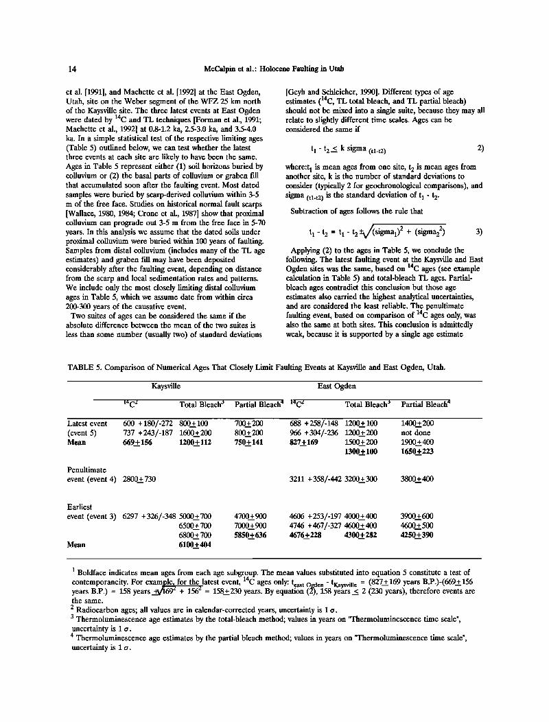
et al. [1991], and Machette et al. [1992] at the East Ogden, Utah, site on the Weber segment of the WFZ 25 km north of the Kaysville site. The three latest events at East Ogden were dated by 14C and TL techniques [Forman et al., 1991; Machette et al., 1992] at 0.8-1.2 ka, 2.5-3.0 ka, and 3.5-4.0 ka. In a simple statistical test of the respective limiting ages (Table 5) outlined below, we can test whether the latest three events at each site are likely to have been the same. Ages in Table 5 represent either (1) soil horizons buried by colluvium or (2) the basal parts of colluvium or graben fall that accumulated soon after the faulting event. Most dated samples were buried by scarp-derived colluvium within 3-5 m of the free face. Studies on historical normal fault scarps [Wallace, 1980, 1984; Crone et al., 1987] show that proximal colluvium can prograde out 3-5 m from the free face in 5-70 years. In this analysis we assume that the dated soils under proximal colluvium were buried within 100 years of faulting. Samples from distal colluvium (includes many of the TL age estimates) and graben fill may have been deposited considerably after the faulting event, depending on distance from the scarp and local sedimentation rates and patterns. We include only the most closely limiting distal colluvium ages in Table 5, which we assume date from within circa 200-300 years of the causative event.
Two suites of ages can be considered the same if the absolute difference between the mean of the two suites is
less than some number (usually two) of standard deviations
[Geyh and Schleicher, 1990]. Different types of age estimates (14C, TL total bleach, and TL partial bleach) should not be mixed into a single suite, because they may all relate to slightly different time scales. Ages can be considered the same if
t 1 - t 2 < k sigma (tl-t2) 2)
where:tl is mean ages from one site, t 2 is mean ages from another site, k is the number of standard deviations to consider (typically 2 for geochronological comparisons), and sigma (tl-t2) is the standard deviation of tl - t 2.
Subtraction of ages follows the rule that
t 1 - t 2 = t 1 - t 2 +•sigmal) 2 + (sigma22) 3) Applying (2) to the ages in Table 5, we conclude the
following. The latest faulting event at the Kaysville and East Ogden sites was the same, based on •4C ages (see example calculation in Table 5) and total-bleach TL ages. Partial- bleach ages contradict this conclusion but those age estimates also carried the highest analytical uncertainties,
Th½• and are considered the least reliable. enultimate
faulting event, based on comparison of •4 ages only, was also the same at both sites. This conclusion is admittedly weak, because it is supported by a single age estimate
TABLE 5. Comparison of Numerical Ages That Closely Limit Faulting Events at Kaysville and East Ogden, Utah.
Kaysville East Ogden
14C2 Total Bleach 3 Partial Bleach • 14C2 Total Bleach 3 Partial Bleach 4
Latest event 600 + 180/-272 800+ 100 700+200 688 + 258/-148 1200+ 100 1400+200 (event 5) 737 + 243/-187 1600+200 800+200 966 + 304/-236 1200+200 not done Mean 669 + 156 1200+ 112 750+ 141 827 + 169 1500 + 200 1900 + 400
1300+ 100 1650+ 223
Penultimate
event (event 4) 2800+ 730 3211 + 358/-442 3200+ 300 3800+400
Earliest
event (event 3) 6297 + 326/-348 5000+700 6500 + 700
6800 + 700
Mean 6100+404
4700+ 900 4606 + 253/-197 4000__+ 400 3900+600 7000+ 900 4746 + 467/-327 4600+ 400 4600+500 5850+636 4676+ 228 4300+ 282 4250+ 390
1 Boldface indicates mean ages from each age subgroup. The mean values substituted into equation 5 constitute a test of contemporaneity. For exampl% for the latest event, •4C ages only' t .... t ...... (827 + 169 years B P )-(669+ 156 ., ß east ul•aen •,aysmne -- ' ' -- years B.P.) = 158 years _-•692 + 156 •' = 158+230 years. By equation (2), 158 years < 2 (230 years), therefore events are the same.
2 Radiocarbon ages; all values are in calendar-corrected years, uncertainty is 1 o. 3 Thermoluminescence age estimates by the total-bleach method; values in years on "Thermoluminescence time scale", tincertainty is 1 o. 4 Thermoluminescence age estimates by the partial bleach method; values in years on "Thermoluminescence time scale", uncertainty is 1 o.

McCalpin et al.' Holocene Faulting in Utah 15
(based on soil accumulation rates) at Kaysville. For the earliest faulting event, all suites of age estimates at the two sites (14C and TL) fail the test of contemporaneity; therefore we conclude that these events could not have been
the same.
The age comparison above implies that the 3.5-4.0 ka surface rupture at East Ogden died out before reaching the Kaysville site, 25 km to the south. The earliest event at Kaysville (5.7-6.1 ka?), in contrast, was probably too old to have been detected at East Ogden, where trenches were excavated in a mid-Holocene fan circa 5 ka. Due to the
limited scope of our investigation, we are unable to explain exactly why a surface rupture with over 5 m vertical displacement at East Ogden would die out within the Weber segment. One possibility is that a subsegment boundary exists between the two sites. For example, Machette et al. [1987] suggested that the Provo segment (at 69 km the longest segment of the WFZ) was composed of subsegments, although more recent studies have modified that view [Machette et al., 1992]. In the latest segmentation analysis of the WFZ, Wu (1993) proposes that the Weber segment is composed of two subsegments, termed the Ogden (northern) and Bountiful (southern) subsegments, with the boundary at Weber Canyon. This subsegment boundary was defined on the basis of a large-scale wavelength analysis of fault scarps, so it lacks the multiple geological and geophysical anomalies associated with the other major segment boundaries of the WFZ [Wheeler and Krystinik, 1992]. Variations in fault scarp height along strike also permit the possibility of some kind of discontinuity at Weber Canyon [Nelson and Personius, 1990, Figure 2]. A subsegment boundary at Weber Canyon thus currently provides the most reasonable explanation for the diachroneity of earliest events at the two well-dated trench sites.
A final difference between the chronology of events at the Kaysville and East Ogden sites is the absen•ce of evidence for a very young paleoearthquake at about 500 years B.P. at Kaysville. Such an event was postulated by Machette et al. [1992, Figure 12, event D] at East Ogden, but the evidence for the event was found in only one of five trenches and in only one of two trenches on the same fault scarp. In addition, the well-dated exposure at Garner Canyon, 5 km north of East Ogden, shows no evidence for a 500-year event; the latest event there is dated at 0.8-1.2 ka. Despite the ambiguous stratigraphic evidence for a 500-year event at East Ogden, it was considered as probable because Swan et al. [1980, 1981] had dated the latest event at Kaysville as very young, circa 500 years B.P. As we have shown in this paper, however, the latest event at Kaysville actually occurred before 0.6-0.8 ka and cannot be used as supporting evidence for a very young event at East Ogden. The lack of a 500-year event at either the Garner Canyon site or the Kaysville site, on either side of the East Ogden site, casts
doubt on the validity of the proposed 500- year event at East Ogden [Machette et al., 1992].
CONCLUSIONS
Detailed stratigraphic analysis and geometrical reconstructions from the 1978 and 1988 Kaysville trenches reveal evidence for five to six paleoseismic events in the past 13 ka. Our reconstructions rely heavily on the sedimentology of graben deposits and indicators of original dip angle, such as pebble orientations in colluvium. The latest three faulting events (3-5) were accompanied by net vertical displacements of 1.4 to 3.4 m, by eastward tilting of the graben of 20-5.5 ø, and by antithetic faulting of 2.2 m per event. Evidence for the earlier two to three paleoseismic events is presumably buried beneath the trench floor.
Four radiocarbon and five TL age estimates are used to date the latest faulting event as slightly older than 0.6-0.8 ka, the penultimate event shortly before 2.• 0.7 ka, and the earliest event around 3.8-7.9 ka (preferred age range 5.7-6.1 ka). TL age estimates from buried soil A horizons are generally concordant with MRT-corrected radiocarbon ages from the same horizons, whereas TL age estimates from fine-grained sag pond silts indicate much older ages than suggested by radiocarbon ages and stratigraphy of Lake Bonneville. We infer that sag pond silts in large grabens may accumulate rapidly (Figure 2) in perennial ponds without initial "zeroing" of TL. In contrast, silts from small, intermittent sag ponds are well zeroed and yield accurate TL estimates of deposit age [Forman et al., 1989, 1991].
The two latest faulting events dated at Kaysville correlate well with the two latest events at East Ogden, 25 km to the north on the Weber segment. A third event recognized at East Ogden (3.4-4.0 ka) cannot be identified by any tectonic or depositional features at Kaysville. This event may have died out within the Weber segment, at a possible subsegment boundary at Weber Canyon which lies between the two trench sites.
Acknowledgments. We thank Ray Harvey of Fruit Heights, Utah, for allowing trenching on his property and the County Commissioners of Davis County, Utah, for providing excavating equipment and personnel. The Utah Geological and Mineral Survey provided hydraulic trench shores. D. P. Schwartz contributed many helpful observations about the 1978 trench and radiocarbon sample and also reviewed this paper, although he does not necessarily concur with our reevaluation of fault chronology. A. R. Nelson and M. N. Machette provided critical reviews and editorial comments on this paper. D. Wu provided unpublished data on the segmentation of the Weber segment. S. P. Nishenko showed J.P.M. how to test suites of radiocarbon ages for contemporaneity. This research was supported by U.S. Geological Survey contract 14-08-0001-G1396.
REFERENCES
Blair, T. C. and W.L. Bilodeau, Development of tectonic cyclothems in rift, pull-apart, and foreland basins; sedimentary response to
episodic tectonism, Geology, 1__6, 517-520, 1988. Bonilla, M. G., R.K. Mark, and J.J.
Lienkaemper, Statistical relations among
earthquake magnitude, surface rupture length, and surface fault displacement• Bull. Seismol. Soc. Am.• 74, 2379-2411, 1984.
16 McCalpin et al.: Holocene Faulting in Utah
Crone, A. J., M. N. Machette, M. G. Bonilla, J. J. Lienkaemper, K. L. Pierce, W. E. Scott, and R. C. Bucknam, Surface faulting accompanying the Borah Peak earthquake and segmentation of the Lost River fault, central Idaho T Bull. Seismol. Soc. Am.• 77, 739-770, 1987.
Currey, D. R. and G. C. Oviatt, Durations, average rates, and probable causes of Lake Bonneville expansions, stillstands, and contractions during the last deep-lake cycle, 32,000 to 10,000 years ago, in Problems of and Prospects for Predicting Great Salt Lake Levels, edited by P. A. Kay amd H. F. Diaz, pp. 9-24, Center for Public Affairs and Administration, University of Utah, Salt Lake City, 1985.
Forman, S. L., Application and limitations of thermoluminescence to date Quaternary sediments, Quat. Int. T 1, 47-59, 1989.
Forman, S. L. and M. N. Machette, Thermoluminescence dating of terrestrial sediment, in The Geology of North America• vol. K2• Quaternary Non-Glacial Geology of the Conterminus United States, edited by R. B. Morrison, pp. 61-65, Geological Society of America, 1991.
Forman, S. L., M. N. Machette, M. E. Jackson, and P. Maat, An evaluation of thermoluminescence dating of paleoearthquakes on the American Fork segment, Wasatch fault zone, Utah, J. Geophys. Res.• 94, 1622-1630, 1989.
Forman, S. L., A. R. Nelson, and J.P. McCalpin, Thermoluminescence dating of fault scarp derived colluvium: Deciphering the timing of paleoearthquakes on the Wasatch fault zone, north-central Utah, J. Geophys. Res.• 96, 595-605, 1991.
Geyh, A. A. and H. Schleicher, Absolute Age Determination, Springer-Verlag, New York, 1990.
Hanson, K.L. and D. P. Schwartz, Guidebook to Late Pleistocene and Holocene faulting along the Wasatch Front and vicinity - Little Cottonwood Canyon to Scipio, Utah, Chapman Conference on Fault Behavior and The
Earthquake Generation Process T AGU, Snowbird, Utah, Oct. 11-15, 1982.
Kihl, R., Appendix: Physical preparation of organic matter samples for C14 dating, Radiocarbon date list II from Cumberland
Peninsula, Baffin Island, N.W.T., Canada, Arct. Alp. Res.• 7, 90-91, 1975.
Leeder, M. R. and R. I. Gawthorpe, Sedimentary models for extensional tilt block/half-graben basins, in Continental Extensional Tectonics, edited by M.P. Coward, J. F. Dewey, and P. L. Hancock, Geol. Soc. London Spec. Pub. 28, 139-152, 1987.
Machette, M. N., S. F. Personius, A. R. Nelson, D. P. Schwartz, and W. R. Lund, The Wasatch fault zone, Utah-- segmentation and history of Holocene earthquakes, J. Str. Geol., 13, 137- 149, 1991.
Machette, M. N., S. F. Personius, and A. R. Nelson, Paleoseismology of the Wasatch fault zone -- a summary of recent investigations,
conclusions, and interpretations, in Assessment of Regional Earthquake Hazards and Risk along the Wasatch Front, Utah, edited by P. L. Gori and W. W. Hays, U.S. Geol. Surv. Prof. Pap. 1500-A, A1-A72, 1992.
McCalpin, J., Quaternary geology and neotectonics of the west flank of the northern
Sangre de Cristo Mountains, south-central Colorado, Colo. Sch. Mines Q., 77(3), 97 pp., 1983.
McCalpin, J., Thermoluminescence (TL) dating in seismic hazard evaluations: an example from the Bonneville Basin, Utah, Proc. Symla. En•. Geol. Soils Eng.• 22nd, 156-176, 1986.
McCalpin, J., Recommended setback distances from active normal faults, Proc. Syrup. on Eng. Geol. Soils Eng.• 23rd, 35-56, 1987.
McCalpin, J., Current investigative techniques and interpretive models for trenching active dip-slip faults, Proc. Symp. Eng. Geol. Geotech. Eng.• 25th, 249-258, 1989.
McCalpin, J., and S. L. Forman, Quaternary faulting and thermoluminescence dating of the East Cache fault zone, north-central Utah,__ Bull. Seismol. Soc. Amer.• 81, 139-161, 1991.
McCalpin, J.P., W. Zuchiewicz, and L. C. A. Jones, Sedimentology of fault-scarp-derived colluvium from the 1983 Borah Peak rupture, central Idaho, J. Sediment. Petrol. T 63, 120-130, 1993.
Nash, D. B., Morphological dating of degraded normal fault scarps, J. Geol. T 88, 353-360, 1980.
Nelson, A. R., The northern part of the Weber segment of the Wasatch fault zone near Ogden, Utah, in In the Footsteps of G.K. Gilbert--Lake Bonneville and Neotectonics of
the Eastern Basin and R.ange Province, edited by M. N. Machette• Utah Geol. Miner. Surv. Misc. Publ. T 88-1, 33-37, 1988.
Nelson, A. R., Lithofacies analysis of colluvial sediments-- An aid in interpreting the recent history of Quaternary normal faults in the Basin and Range province, western United States, J. Sediment. Petrol.• 62,607-621, 1992.
Nelson, A. R. and S. F. Personius, Preliminary surficial geologic map of the Weber segment, Wasatch fault zone, Weber and Davis Counties, Utah, scale 1:50,000, U.S. Geol. Surv. Misc. Field Stud. Map• MF-2132, 22 pp., 1990.
Nelson, A. R. and S. F. Pe•sonius, Surficial geologic map of the Weber segment, Wasatch fault zone, Weber and Davis Counties, Utah, scale 1:50,000, U.S. Geol. Surv. Misc. Invest. Map• 1-2199, 1993.
Nelson, A. R. and R. B. Van Arsdale, Recurrent late Quaternary movement on the Strawberry normal fault, Basin and Range-Colorado Plateau transition zone, Utah, Neotectonics T 1, %37, 1986.
Ostenaa, D. A., Relationships affecting estimates of surface fault displacements based on scarp-derived colluvial deposits, Geol. Soc. Am. Abstr. Programs T 16, 327, 1984.
Schwartz, D. P. and K. J. Coppersmith, Fault behavior and characteristic
earthquakes--Examples from the Wasatch and
San Andreas fault zones, J. Geophys. Res.• 89, 5681-5698, 1984.
Scott, W. E., W. D. McCoy, R. R. Shroba, and M. Rubin, Reinterpretation of the exposed record of the last two lake cycles of Lake Bonneville, western United States, Quat. Res. T 20, 261-285, 1983.
Slemmons, D.B., Geological effects of the Dixie Valley-Fairview Peak, Nevada, earthquakes of December 16, 1954, Bull. Seismol. Soc. Amer.. 47, 353-375, 1957.
Stephenson, W. J., R. B. Smith, and J. R. Pelton, A high-resolution seismic reflection and gravity survey of Quaternary deformation across the Wasatch fault, Utah, J. Geophys. Res.• 98, 8211-8223, 1993.
Stuiver, M. and P. J. Reimer, A computer program for radiocarbon age calibration,__ Radiocarbon• 28, 1022-1030, 1986.
Swan, F. H. III, D. P. Schwartz, and L. S. Cluff, Recurrence of moderate to large magnitude earthquakes produced by surface faulting on the Wasatch fault, Utah, Bull. Seismol. Soc. Am. T 70, 1431-1462, 1980.
Swan, F. H. III, D. P. Schwartz, K. L. Hanson, P. L. Knuepfer, and L. S. Cluff, Study of earthquake recurrence intervals on the Wasatch fault at the Kaysville site, Utah, U.S. Geol. Surv. Open File Rep.• 81-228, 30 pp., 1981.
Wallace, R. E., Profiles and ages of young fault scarps, north-central Nevada• Geol. Soc. Am. Bull.• 88, 1267-1281, 1977.
Wallace, R. E., Degradation of the Hebgen Lake fault scarps of 1959, Geolok, v, 8, 225-229, 1980.
Wallace, R. E., Fault scarps formed during the earthquakes of October 2, 1915, in Pleasant Valley, Nevada, and some tectonic implications, U.S. Geol. Surv. Prof. Pap.• 1274-
__A, A1-A33, 1984. Warren, G. A. and J.P. McCalpin, Quaternary
faulting on the southern Star Valley fault, western Wyoming: Geol. Soc. Am. Abstr. Programs, 24(6), 67, 1992.
Wheeler, R. B. and K. B. Krystinik, Persistent and nonpersistent segmentation of the Wasatch fault zone, Utah: statistical analysis for evaluation of seismic hazard, in Assessment of Regional Earthquake Hazards and Risk Along the Wasatch Front, Utah, edited by P. L. Gori, and W. W. Hays, U.S. Geol. Surv. Prof. Pap. 1500-B, B1-B47, 1992.
S. L. Forman, Department of Geology, Ohio State University, Columbus, OH 43210
M. Lowe, Utah Geological Survey, 2363 South Foothill Drive, Salt Lake City, UT 84109
J.P. McCalpin, Department of Geology, Utah State University, Logan, UT 84322
(Received May 5, 1992; revised July 23, 1993; accepted July 28, 1993.)