reddington setback levee erosion protection basis of ... · subject: reddington setback levee...
TRANSCRIPT
Memorandum Northwest Hydraulic Consultants 16300 Christensen Road, Suite 350 Seattle, WA 98188 206.241.6000 206.439.2420 (fax)
DATE: January 16, 2013 NHC PROJECT: 0200051 TO: Tom Bean COMPANY/AGENCY: King County WLRD FROM: Vaughn Collins, P.E., NHC Erik Peters, P.E., King County WLRD SUBJECT: Reddington Setback Levee Erosion Protection Basis of Design Fish Habitat Considerations –
Final
This memorandum summarizes the design objectives and analysis conducted in designing the system of rock barbs, rock revetments and engineered log jams (ELJs) used to protect the proposed levee from river erosion and scour risk and improve fish habitat conditions. Project design alternatives were assessed for their ability to meet project objectives and reviewed by King County, key stakeholders and permit agencies at 30% and 60% designs. Items addressed in this memorandum include: examples of similar ELJs to those proposed here; other design alternatives considered; bench elevations; inundation area – duration analysis; and expected channel and floodplain evolution under with-project conditions.
1 Design Approach – Overview
1.1 Overall Project Objectives
• Reduce the risks from flood and channel migration hazards • Avoid or minimize the environmental impacts of flood hazard management • Reduce the long-term cost of flood hazard management • Protect the levee from river scour and meet current engineering design guidelines for levee
stability.
1.2 Guiding Approach for Engineered Features to Address River Migration and Scour
• The design should account for erosion and scour risk to the setback levee in the 20-year time frame. Levee segments where the river may migrate within 20 years should not require any corrective action when exposed to river flows. For areas of the levee not expected to see exposure to main channel flows within 20 years, the design may consider lower cost alternatives including monitoring and adaptive management.

Page 2
water resource specialists
• Engineered log jams (ELJ) and other habitat-related work should be designed to meet erosion protection requirements and provide habitat benefits.
• Erosion protection design is of primary importance, but existing trees should be retained where possible.
• To allow for river function improvement, the existing levee prism will be partially removed from the floodplain as well as visible rock revetment. Individual rocks that might aid potential tree retention along the existing levee will be left in place. Riprap removal will extend below the Ordinary High Water Mark as this will be of most benefit to allow future natural channel evolution.
• Relocation of the Tacoma Water pipeline is cost prohibitive. Protection of this existing infrastructure is an important design objective. King County intends to seek Tacoma Water concurrence with project design.
• Boater safety is an important design objective that requires consideration, especially where the designs include large wood.
1.3 Key Geomorphic Findings A geomorphic assessment for the project is documented in an accompanying NHC memorandum. Key findings from the geomorphologic assessment are:
• The river has exhibited very little tendency towards large scale channel migration behavior in the last century. In the decades since the White River diversion and Howard Hanson Dam (HHD) construction, the river has been characterized by narrowing and incision within its planform. In the past 15 years, the river channel profile in the project area has remained relatively stable based on USGS Auburn gage data and channel mapping comparisons, suggesting equilibrium has been reached.
• Future behavior is expected to include progressive meander bend erosion (primarily through downstream translation) where not confined by revetments, but generally no avulsions or major changes to planform are expected because of the relatively narrow river corridor. Due to the unique situation in the River Mobile Estates (RME) wetland, channel changes here may be more rapid and complex; this is discussed further below.
• The river has built (in the few areas available to it) a lower, inset floodplain surface that is considered representative of future conditions.
Channel migration risk maps were produced for this assessment and were used to guide design decisions on type and extent of erosion protection for the various levee segments. This assessment was also used in the scour analysis.
1.4 Design Process and Justification for Basis of Design Project objectives, guiding principles, and the geomorphologic analysis were the primary components used to develop erosion protection designs for the proposed levee. In order to minimize costs and habitat impacts, a segmented design approach was used. The levee was broken into lengths of similar character, primarily based on current and projected future channel location and trends from the geomorphologic analysis. For each segment, a three-step evaluation was completed to determine the basic design approach:
Page 3
water resource specialists
• First, it was determined if levee erosion protection was not needed within the 20-50 year timeframe. Two segments were judged not to need protection in this period; they are described under the “No Levee Scour Protection” approach described in Section 1.4.1 below.
• Where it was determined erosion protection was required, the design preference was to allow channel migration near, but not up to, the levee face itself. This is referred to as the “Riparian Buffer” approach (Section 1.4.2). There were three primary reasons for this design approach:
o Allowing the river to migrate completely to the levee face increases geotechnical stability risk and in some cases makes it difficult to meet standard factors of safety.
o The proposed design improves habitat conditions by planting and allowing retention of a forested riparian buffer rather than allowing additional channel migration to the levee toe. Should the channel migrate to the levee face only minimal shade and overhanging cover would be provided by a thin screen of trees on the lower bank.
o While the project will incorporate vegetation on levee slopes, the U.S. Army Corps of Engineers is in the process of revising its policy regarding vegetation on levees. In that light, there is uncertainty regarding future management of vegetation on levee slopes. Buffer areas between the levee and channel provide more certain opportunity to provide shade and other important riparian forest functions.
• Where neither of the first two options were deemed practical, erosion protection on and immediately adjacent to the levee face itself was the only remaining design option. This is referred to as the “Protect Levee Face” approach (Section 1.4.3).
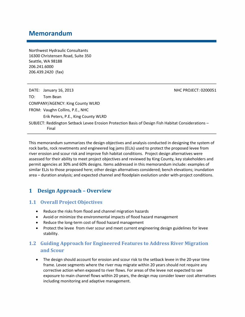
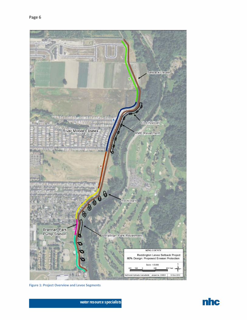
The following sections group each segment by the design approach used, and provide specific details on each segment. Figure 1 shows the proposed project elements and levee segments.
1.4.1
Two levee segments were identified as not needing scour protection - the threat of channel migration toward the setback levee was considered low within the design timeframe.
No Levee Scour Protection Approach
Segment 4:
Segment 4 is the levee length located on the inside of an existing river bend and containing the Tacoma Water pipeline. Risk to the pipeline is limited to the end of the shallow portion of the pipe which ends just landward of the existing levee. The upstream barbs protect the pipeline from channel migration; therefore, no bank protection in the form of barbs or revetments is needed within this segment itself. The pipeline itself is buried under higher ground that modeling indicates will be barely flooded even under 100-year flood conditions. No high velocity overbank flows and surface erosion is expected; therefore, no surface protection over the pipeline itself is necessary either.
Segment 6:
Segment 6 is at the north end of the project, where the setback levee alignment is consistently distant from the channel. The geomorphologic analysis shows the river has been very stable here. Combined with its location on the inside of the bend, channel migration into the setback levee is considered unlikely in the next few decades and therefore armoring is not proposed at this time.
1.4.2
A variety of structures were evaluated that could provide the desired function of allowing the river to migrate near to the levee but reliably prevent it from proceeding beyond a safe buffer distance for
Riparian Buffer Approach
Page 4
water resource specialists
Segments 1 and 3. The proposed design consists of rock barbs and independently ballasted loose wood pieces placed on the downstream side of each barb. Alternative designs, including relying on ELJs and log revetments were evaluated but determined to be less suitable, are discussed in Section 2.
The barb design provides both the levee erosion protection needed for the long term and habitat benefits, as follows:
• Separation of wood and rock alleviates concerns with wood decay resulting in voids in the armor layer.
• Use of rock provides long-term erosion protection for the levee. • The barbs themselves will create new habitat benefits for juvenile salmonids over the long term,
including the creation of new natural bank, and shallow slow water areas between each barb (see Table 2).
• As the barb is exposed to river flow, the ballasted wood is intended to launch into the scour hole that will develop off the downstream tip of the barb, thereby providing cover and habitat benefits during all flow.
• Placing wood in the lee of the barbs alleviates concerns with boater safety issues.
Segment 1:
Segment 1 extends from the upstream end of the proposed levee to the Brannan Park Pump Station. The proposed design is a series of buried rock barbs. The barbs are oriented at 45 degrees to the bank. The outer thirty feet slope down at a 10:1 slope to allow progressive overtopping of the barb under increasing water levels. The tapered tip reduces scour depths as compared to a blunt tip. The purpose of the barbs is to promote channel migration into the floodplain but halt it before it reaches the levee itself. As erosion begins, increasing lengths of barb will be exposed until the barbs begin to act as a system in limiting further erosion between them. Under this condition, the bank will consist of a series of exposed barbs with scalloped natural bank created by the river in between each one. The remaining floodplain between the levee and bankline serves as a buffer, allowing development of a riparian forest over time; no armoring is required on the levee itself.
The barb top elevations are set at the expected future inset floodplain surface to allow floodplain creation to occur should the river migrate away from the levee over time. The proposed grading leaves the ground surface over the centerline of each barb at this lower design floodplain elevation. This creates a series of floodplain alcoves that will flood on a more frequent basis than the existing high ground in between them, providing flood refugia. Independently ballasted LWD is placed on the downstream side of each barb.
Segment 3:
Segment 3 encompasses the setback levee paralleling the existing City of Auburn water quality swale and a short distance downstream. In terms of design, it is very similar to segment 1, using rock barbs to allow limited channel migration while providing erosion protection to the setback levee. Independently ballasted LWD is also added to the downstream sides of these barbs. This segment is expected to undergo active erosion soon after project completion due to its location on the outer side of the existing bend. The barbs have been designed to be the minimum length needed to protect the new levee while allowing maximum migration. The barbs extend downstream to the crossing between bends. By doing so, downstream meander translation is limited and the general channel alignment kept into the crossing to the next downstream bend. This provides the protection needed for the Tacoma Water pipeline without extensive armoring around the pipeline itself.
Page 5
water resource specialists
1.4.3
The proposed design utilizes rock revetments at the Brannan Park Pump Station and River Mobile Estates, with modifications from the Feasibility Study design. In both locations the existing bank is pulled back to minimize impacts in wetlands or below the OHWM. Alternative revetment designs were considered and determined to have lower benefits or be infeasible as discussed in Section 2.2.
Protect Levee Face Approach
The proposed design utilizes deep excavation – the estimated limits possible without dewatering – in order to provide a constructed revetment that utilizes less rock and a smaller launch toe. The rock is also ended at the 10-year flood level rather than extended up to the top of levee. Willows are incorporated into both revetments. Specific design details for each revetment are discussed below.
Segment 2:
Segment 2 is a short length immediately adjacent to the Brannan Park Pump Station. A rock revetment is proposed here due to the horizontal space constraints imposed by the pump station. The protection will be keyed into the upstream barb and wrapped around the downstream end. The existing revetment will be removed and the bank pulled back and re-graded to a 2.5H:1V slope before being re-armored. The thickened rock blanket at the toe provides the launch rock volume necessary to protect the levee from scour. Excavation for this segment will extend down to just above summer low water levels. Two willow lifts are incorporated into the revetment to provide shading and vegetation. No soil cap is proposed due to the river’s proximity and likely erosion of any soil cap placed on the rock revetment.
Segment 5:
Segment 5 primarily comprises the levee and bank of the wetland meander at River Mobile Estates. Migration into this wetland is considered very likely over time. Barbs were evaluated here but it was determined that the impact on the wetlands would be too extensive. The proposed design minimizes wetland impacts by grading the bank back and using an armored revetment with a launch toe (bench) on the levee face. A soil cap and coir lifts are proposed to be placed over the revetment to allow better vegetation growth, including three willow layers.
ELJs are designed as eight clusters along the revetment. Small rock spurs are used to support ELJs along the face. The revetment does not require the ELJs for protection, allowing for the chance some of them may decay in the future. The ELJs are designed to encourage accretion on the rock bench and the wetlands between each structure. Over time, this will build up to natural floodplain levels and allow the establishment of a riparian buffer between the river and the rock levee face. Construction of the bench also provides a working surface for installation of the erosion protection along the toe and the bank/levee face.
Page 6
water resource specialists
Figure 1: Project Overview and Levee Segments
Page 7
water resource specialists
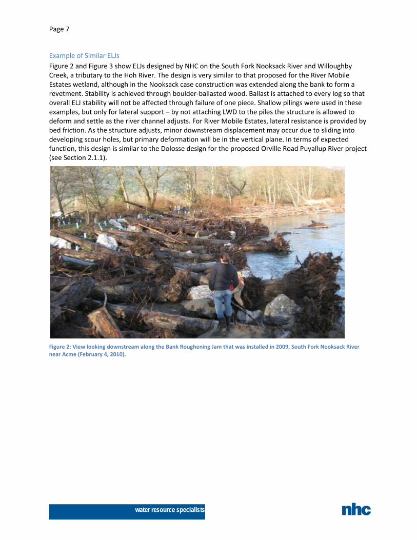
Example of Similar ELJs Figure 2 and Figure 3 show ELJs designed by NHC on the South Fork Nooksack River and Willoughby Creek, a tributary to the Hoh River. The design is very similar to that proposed for the River Mobile Estates wetland, although in the Nooksack case construction was extended along the bank to form a revetment. Stability is achieved through boulder-ballasted wood. Ballast is attached to every log so that overall ELJ stability will not be affected through failure of one piece. Shallow pilings were used in these examples, but only for lateral support – by not attaching LWD to the piles the structure is allowed to deform and settle as the river channel adjusts. For River Mobile Estates, lateral resistance is provided by bed friction. As the structure adjusts, minor downstream displacement may occur due to sliding into developing scour holes, but primary deformation will be in the vertical plane. In terms of expected function, this design is similar to the Dolosse design for the proposed Orville Road Puyallup River project (see Section 2.1.1).
Figure 2: View looking downstream along the Bank Roughening Jam that was installed in 2009, South Fork Nooksack River near Acme (February 4, 2010).
Page 8
water resource specialists
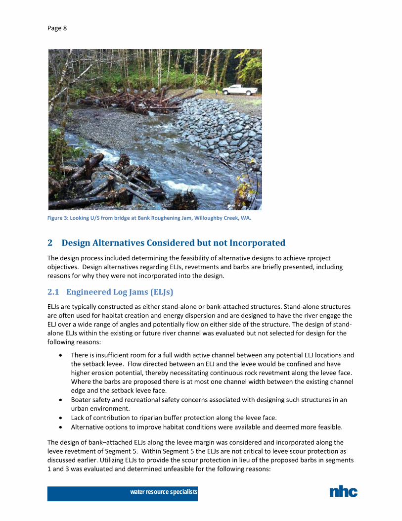
Figure 3: Looking U/S from bridge at Bank Roughening Jam, Willoughby Creek, WA.
2 Design Alternatives Considered but not Incorporated The design process included determining the feasibility of alternative designs to achieve rproject objectives. Design alternatives regarding ELJs, revetments and barbs are briefly presented, including reasons for why they were not incorporated into the design.
2.1 Engineered Log Jams (ELJs) ELJs are typically constructed as either stand-alone or bank-attached structures. Stand-alone structures are often used for habitat creation and energy dispersion and are designed to have the river engage the ELJ over a wide range of angles and potentially flow on either side of the structure. The design of stand-alone ELJs within the existing or future river channel was evaluated but not selected for design for the following reasons:
• There is insufficient room for a full width active channel between any potential ELJ locations and the setback levee. Flow directed between an ELJ and the levee would be confined and have higher erosion potential, thereby necessitating continuous rock revetment along the levee face. Where the barbs are proposed there is at most one channel width between the existing channel edge and the setback levee face.
• Boater safety and recreational safety concerns associated with designing such structures in an urban environment.
• Lack of contribution to riparian buffer protection along the levee face. • Alternative options to improve habitat conditions were available and deemed more feasible.
The design of bank–attached ELJs along the levee margin was considered and incorporated along the levee revetment of Segment 5. Within Segment 5 the ELJs are not critical to levee scour protection as discussed earlier. Utilizing ELJs to provide the scour protection in lieu of the proposed barbs in segments 1 and 3 was evaluated and determined unfeasible for the following reasons:
Page 9
water resource specialists
• ELJs are typically built projecting out from bank or levee on the order of one log length whereas the barbs are designed with projection lengths of 100-140 feet to provide the necessary separation between levee toe and future thalweg location. The design of ELJs with comparable function would require numerous piles and extensive ballast to provide lateral stability. There is no track record of comparable structures being constructed in the Pacific Northwest.
• Geotechnical information indicates that driving timber piles to support ELJs would be extremely difficult due to dense gravel layers encountered. This in turn affects construction cost as pre-drilling each timber pile or use of steel piles would be required.
• A significant spine of rock would be necessary to tie the ELJ to the levee face and ensure that flow does not try to outflank the ELJ and scour the levee.
2.1.1
Dolosse (plural of dolos) or other pre-cast concrete armor units have been used in place of anchored rock as ballast for ELJs. For example, the proposed drawings for Orville Road ELJ Setback Revetment on the Puyallup River by Pierce County include dolosse. We note that for a Green River application, the number of dolosse would need to be significantly greater than those shown on the reference Puyallup project as the jam would be fully overtopped.
Dolosse
Design considerations for incorporation of dolosse include the following:
• Most dolosse are manufactured without structural steel reinforcement. As concrete has weak tensile strength, dolosse are susceptible to fracturing if not evenly supported.
• Dolosse and woody debris should remain interlocked during settlement to prevent loss of key logs
• If designed as part of a structure without piles for lateral support the structures would shift laterally (downstream). The deformation and response to scour for high values of strain becomes difficult to predict.
• The design of riverine projects incorporating dolosse should calculate peak tensile stresses on Dolosse resulting from anticipated static and live loads and account for a level of uncertainty in calculating loads.
For this project, dolosse do not appear to provide an advantage over using chained boulder ballast in construction methods, and material costs would likely be 2-3 times higher.
2.1.2
This concept proposes to use logs with buried rootwads as upright pilings. This creates the equivalent of a bell-end pile, which offers far greater uplift resistance than a straight pile of equal depth. In order for such a concept to work, the rootwad must be protected from scour and laterally supported. Ensuring scour protection requires either placing the rootwad below scour depth, which we do not believe is feasible at the barb locations, or laying a riprap armor layer/apron around the rootwad once placed. Pile resistance requirements against lateral forces would be the same for this concept or a traditional pile, as the cross section above the bed is the same in either case. Consequently this type of piling would require a substantial rock mass around each log to provide lateral support. For this project the rock requirements and lateral stability concerns did not make the use of upright LWD pilings a feasible component for ELJ construction.
Upright LWD Pilings
Page 10
water resource specialists
2.2 Revetments Four revetment designs, including the proposed alternative, were evaluated. Other options evaluated consisted of an alternative method of rock placement and two types of log revetments.
2.2.1
The Feasibility Study proposed armoring the entire levee length with a rock revetment. The design minimized excavation costs by placing most of the rock in a wide, shallow launching apron riverward of the levee. This design was not carried further into design for several reasons including:
Launchable Rock Revetment
• The wide launch apron (60 feet or more) on the surface occupies a significant area that would not support vegetation
• Due to multipliers required when using launching rock to provide the protective rock blanket, total rock volumes are higher than necessary
• A higher quality revetment is produced by placing armor on the levee face to the maximum depth possible and minimizing reliance on launch rock
2.2.2
Log revetments for protection of the levee toe and face in lieu of the proposed rock revetments were evaluated. Revetments are only proposed where the river already is near the proposed levee (Segment 2), or site constraints prevented consideration of other options (Segment 5). In both cases, the revetment protects either important infrastructure (the Brannan Park Pump Station) or numerous homes (River Mobile Estates) immediately adjacent to the levee, in addition to the broader area of protection including a large portion of the City of Auburn. One of the major concerns with log revetments is due to wood decay over time. This can affect the integrity of the revetment, its erosion protection function, and potentially geotechnical risk factors.
Log Revetments along Levee Toe
Log revetments require larger horizontal dimensions for installation than equivalent rock revetments. While a typical rock blanket thickness is around 4- 8 feet horizontally, minimum widths for log revetments are equivalent to log lengths of 25 feet or more. There is very little room at the Brannan Park revetment to work with due to the pump station location. A log revetment here would project into the existing river channel, potentially causing opposite bank erosion.
Given that these revetments are constructed at the limits of the design channel migration corridor, and have at-risk infrastructure and homes immediately behind them, a rock revetment was selected as providing better long term performance and certainty.
2.2.3
Log revetments as a method to retain a riparian buffer in lieu of the proposed barbs (Segments 1 and 3) were also evaluated. The log revetment would be required to be constructed outboard of the levee, leading to a risk of the channel outflanking or getting behind it and thereby putting the levee at risk. To mitigate this, the area between the log revetment and levee would most likely require extensive rock armoring either surficially or in regular spaced cutoff dikes. This would interfere with the desire to have this buffer grow into a mature riparian forest. In contrast, the barb design allows significant lengths of natural bank and unarmored floodplain between each barb.
Log Revetments as River Buffer
Page 11
water resource specialists
2.3 Incorporating Wood into Rock Barbs The concept of building a barb primarily or entirely out of wood rather than rock was evaluated. In our opinion, while wood can be incorporated along the downstream side of rock barbs as is proposed, the barb itself should not be replaced with a wooden structure. Incorporating wood within a barb would add risk and uncertainty to achieving project goals for the following reasons:
• Increases the risk of voids in the rock • Combines materials with significantly different decay rates • Increases uplift forces with or without the recruitment of logs racking on exposed logs
Wood for habitat benefits has been proposed on site and adjacent to the barbs.
3 Bench Elevations Comments were received regarding design bench elevations and concerns these elevations do not provide habitat at typical rearing flows. First it should be noted that due to the removal of the water quality swale from lower Brannan Park, the bench elevations are only used over each barb, with higher ground in between. The bench elevations (top of barbs) are set at the inset floodplain elevation – the long term floodplain elevation the river is building to under the post-White River diversion/post-dam hydrologic and sediment regime. As such, they will only be inundated at around annual peak flows or greater.
Elevations that would be required to provide typical rearing habitat function are essentially main channel bed elevations at or below the OHWM. From a construction cost perspective, excavation to this level between barbs would add substantially to project cost and require removal of additional trees.
Excavation to create low flow rearing habitat in essence expands the main channel area, reducing sediment transport capacity and result in sediment deposition within newly excavated areas. An example of this has occurred on the upper Brannan Park revetment. The river here was graded to a trapezoidal channel prior to revetment placement. Over time, a forested bar has developed on the left bank that the revetment is now buried behind, indicating the dredged shape was larger than what the river could sustain under post-dam conditions. The river appears to be sized for the current hydrologic regime, and thus expansion of channel area through excavation without mechanisms to scour these areas is unlikely to persist as constructed.
The barb design provides such a mechanism by allowing for erosion of the bank between each barb by river forces. In doing so, the river will excavate these areas to sustainably sized embayments that will provide good habitat under typical flow conditions. The barbs will create greater complexity in flow velocities, water depths, and channel margins than under existing conditions.
4 Inundation Area, Flow and Duration Analysis As requested, a revised inundation area analysis has been completed to provide data on expected habitat benefits with the project. The project HEC-RAS model was run for a series of flows from 300 to 13,000 cfs under with-project and without-project conditions. The simulated water surface elevations were mapped on the new topographic surfaces received in November 2012. This revised existing grade surface is based on new ground survey data, including in the River Mobile Estates wetlands. For the future grade (with-project) surface, the 60% design plan grading was mapped onto the new existing
Page 12
water resource specialists
surface. The inundation mapping was accomplished using the HEC-RAS automated mapper tool and 1- foot resolution topographic grids based on the new surfaces. The project reach was broken up into different areas for calculation purposes.
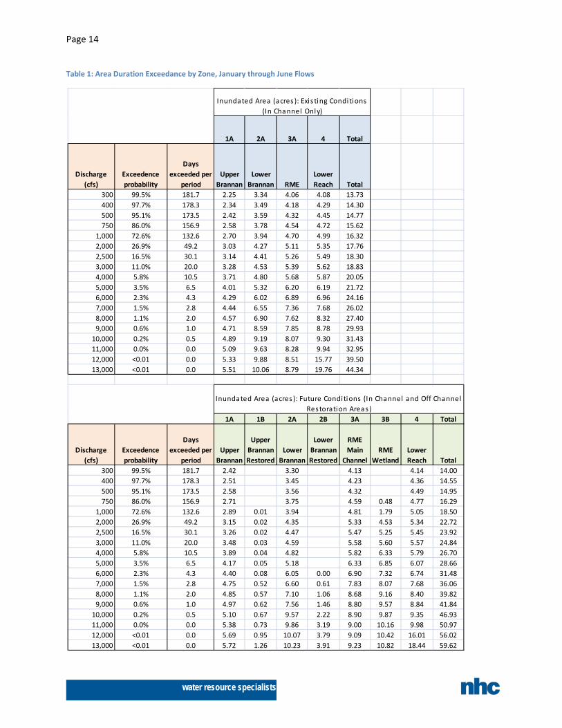
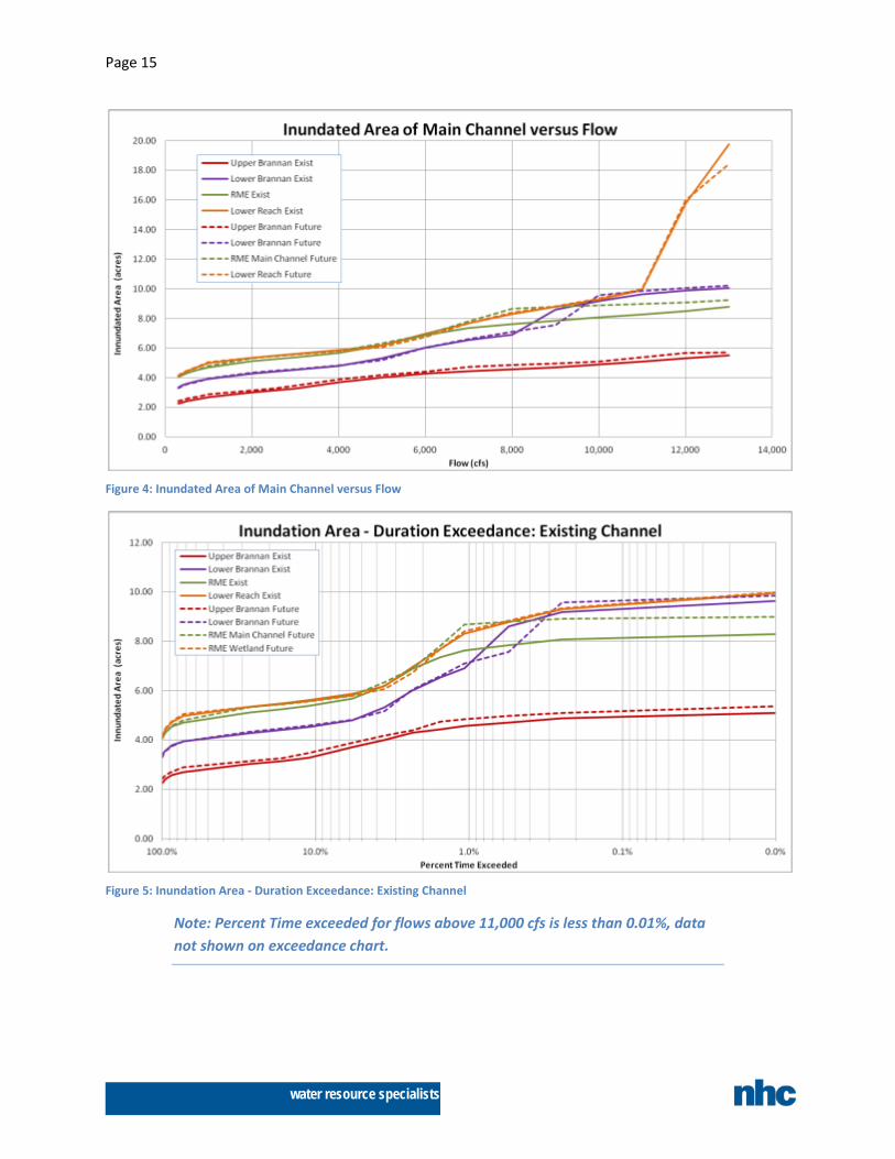
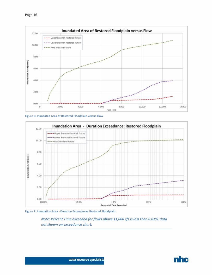
Flow exceedance probabilities were calculated using mean daily flows from January through June for water years 1962-2010 at the Auburn gage. Results are presented for both flow and percent time exceeded. Figure 8 shows mapping outputs for the with-project condition at 2000 cfs and the zones used in the analysis. Note that the zones used do not correspond with the levee segment numbering used elsewhere. Figure 4 and Figure 5 shows results for the main channel, defined as areas riverward of the existing levee crest, for both current and with-project conditions. Figure 6 and Figure 7 show with-project results for newly reconnected areas between the existing and proposed setback levee alignment. The data used in the figures is presented in Table 1. This table can be used to cross reference flow and duration exceedance values. For instance, on average a flow of 2,000 cfs is exceeded 26.9% of the time, or about 49 days, in the January through June period. Some findings of this analysis include:
• The proposed breach elevations will allow flow-through conditions in the RME wetland a significant portion of the time. The current design has both breach elevations set at 45 feet. The downstream breach is located at a culvert crossing (invert 42.7’) and this flow through elevation will be maintained.
• The model results indicate that both breaches will remain fully active to around 1700 cfs. River levels will not drop below the upper breach until 1200 cfs. The end result is that the wetland will see through-flow above 1200 cfs, or about 60% of the time in the January through June time period.
• At lower flows the RME wetland still provides potential backwater habitat benefit through the perennial downstream breach connection – for instance about 2 acres at 1000 cfs.
• The remnant levee prism at RME will begin to be submerged on the lower end at 6,600 cfs and fully submerged by 7,500 cfs. As a result connectivity between the river channel and wetland will occur along the entire reach length during all but the smallest floods.
• The Brannan Park restored areas are graded to inset floodplain elevation, and therefore do not provide significant wetted area until flows reach bankfull, or around 6,000 cfs. Note that over time the proposed barbs will erode a significant portion of this area, thereby creating habitat area at flows below 2,000 cfs.
• As might be expected, there is little change in main channel area with the project implemented. The changes that are shown are partly to existing levee and bank removal and partly due to changes in water levels for a given flow.
Some caveats that should be considered in reviewing these data include:
• The design surfaces use the older topography but the figure is based on the new topography; as a result, the upper and lower breaches at River Mobile Estates show a discontinuity in inundation extents. The modeling indicates that both breaches will be flowing when the river is at 2,000 cfs; in reality there would be a smooth transition in wetted area through the breaches.
• These results are based on a hydraulic model developed and calibrated for high flows. A check against some available data indicates the model is reproducing low flow water surface elevations reasonably well, but the overall accuracy of the model at low flows is not well defined.
• At flows below 1200 cfs, the inundated areas in River Mobile Estates are slightly biased high due to limitations in the mapping tool when areas are under backwater as opposed to flow-through conditions.
Page 13
water resource specialists
• The with-project results are for conditions immediately after construction. No attempt has been made to estimate areas under future channel migration scenarios. Overall, little change in main channel area is expected, so the values given are believed to be reasonable for a longer period of time. The type and quality of habitat within the main channel will change, especially in the vicinity of the barbs, but this has not been evaluated. As discussed in the next section, reconnection of the RME wetland will induce numerous changes to it. As the area accretes to more normal floodplain elevations the wetted areas for given flows below bankfull will decrease. Connectivity of depressions at summer low flows may increase as flow through the breaches erodes a low flow channel.
Page 14
water resource specialists
Table 1: Area Duration Exceedance by Zone, January through June Flows
1A 2A 3A 4 Total
Discharge (cfs)
Exceedence probability
Days exceeded per
periodUpper
BrannanLower
Brannan RMELower Reach Total
300 99.5% 181.7 2.25 3.34 4.06 4.08 13.73400 97.7% 178.3 2.34 3.49 4.18 4.29 14.30500 95.1% 173.5 2.42 3.59 4.32 4.45 14.77750 86.0% 156.9 2.58 3.78 4.54 4.72 15.62
1,000 72.6% 132.6 2.70 3.94 4.70 4.99 16.322,000 26.9% 49.2 3.03 4.27 5.11 5.35 17.762,500 16.5% 30.1 3.14 4.41 5.26 5.49 18.303,000 11.0% 20.0 3.28 4.53 5.39 5.62 18.834,000 5.8% 10.5 3.71 4.80 5.68 5.87 20.055,000 3.5% 6.5 4.01 5.32 6.20 6.19 21.726,000 2.3% 4.3 4.29 6.02 6.89 6.96 24.167,000 1.5% 2.8 4.44 6.55 7.36 7.68 26.028,000 1.1% 2.0 4.57 6.90 7.62 8.32 27.409,000 0.6% 1.0 4.71 8.59 7.85 8.78 29.93
10,000 0.2% 0.5 4.89 9.19 8.07 9.30 31.4311,000 0.0% 0.0 5.09 9.63 8.28 9.94 32.9512,000 <0.01 0.0 5.33 9.88 8.51 15.77 39.5013,000 <0.01 0.0 5.51 10.06 8.79 19.76 44.34
1A 1B 2A 2B 3A 3B 4 Total
Discharge (cfs)
Exceedence probability
Days exceeded per
periodUpper
Brannan
Upper Brannan Restored
Lower Brannan
Lower Brannan Restored
RME Main
ChannelRME
WetlandLower Reach Total
300 99.5% 181.7 2.42 3.30 4.13 4.14 14.00400 97.7% 178.3 2.51 3.45 4.23 4.36 14.55500 95.1% 173.5 2.58 3.56 4.32 4.49 14.95750 86.0% 156.9 2.71 3.75 4.59 0.48 4.77 16.29
1,000 72.6% 132.6 2.89 0.01 3.94 4.81 1.79 5.05 18.502,000 26.9% 49.2 3.15 0.02 4.35 5.33 4.53 5.34 22.722,500 16.5% 30.1 3.26 0.02 4.47 5.47 5.25 5.45 23.923,000 11.0% 20.0 3.48 0.03 4.59 5.58 5.60 5.57 24.844,000 5.8% 10.5 3.89 0.04 4.82 5.82 6.33 5.79 26.705,000 3.5% 6.5 4.17 0.05 5.18 6.33 6.85 6.07 28.666,000 2.3% 4.3 4.40 0.08 6.05 0.00 6.90 7.32 6.74 31.487,000 1.5% 2.8 4.75 0.52 6.60 0.61 7.83 8.07 7.68 36.068,000 1.1% 2.0 4.85 0.57 7.10 1.06 8.68 9.16 8.40 39.829,000 0.6% 1.0 4.97 0.62 7.56 1.46 8.80 9.57 8.84 41.84
10,000 0.2% 0.5 5.10 0.67 9.57 2.22 8.90 9.87 9.35 46.9311,000 0.0% 0.0 5.38 0.73 9.86 3.19 9.00 10.16 9.98 50.9712,000 <0.01 0.0 5.69 0.95 10.07 3.79 9.09 10.42 16.01 56.0213,000 <0.01 0.0 5.72 1.26 10.23 3.91 9.23 10.82 18.44 59.62
Inundated Area (acres ): Future Conditions (In Channel and Off Channel Restoration Areas)
Inundated Area (acres ): Exis ting Conditions (In Channel Only)
Page 15
water resource specialists
Figure 4: Inundated Area of Main Channel versus Flow
Figure 5: Inundation Area - Duration Exceedance: Existing Channel
Note: Percent Time exceeded for flows above 11,000 cfs is less than 0.01%, data not shown on exceedance chart.
Page 16
water resource specialists
Figure 6: Inundated Area of Restored Floodplain versus Flow
Figure 7: Inundation Area - Duration Exceedance: Restored Floodplain
Note: Percent Time exceeded for flows above 11,000 cfs is less than 0.01%, data not shown on exceedance chart.
Page 17
water resource specialists
5 Expected Post-Project Channel and Floodplain Evolution This section provides a narrative and an accompanying figure on how the channel and floodplain evolution within the project reach is expected to change once construction is complete. The focus is on potential changes in the next twenty years or so. It must be emphasized that what is presented here represents one potential future among many. The only quantitative component used is average meander migration rates based on historical data; added to this is qualitative geomorphologic analysis and professional judgment. Figure 9 shows graphically what is discussed herein.
The project geomorphology report documents the work that forms the basis for the following analysis, but was written to serve a different purpose. The geomorphology report was used to guide design and risk analysis as described earlier. As such, the hazard mapping developed shows estimates of channel migration from all possible scenarios over a variety of time windows. The zones used are deliberately coarse; they encompass a range of probabilities within them but to show finer resolution would imply greater confidence in the work than is warranted. The hazard mapping also factors in the possibility of local perturbances such as a log jam occurring anywhere along the reach. In contrast, Figure 9 shows two potential future configurations based primarily on professional judgment of what one reasonably likely scenario may be. The channel positions shown in Figure 9 fall into the appropriate hazard zones in the hazard mapping, but the hazard zones encompass much wider areas.
5.1 Segment 1: Upper Brannan Park This reach is fairly straight, with a slight meander to the right bank in the location of the forested bar on the left bank. Change due to meander migration might be expected to be relatively limited erosion of the upper end of the forested bar in the next two decades; the bar formed naturally inside a dredged trapezoidal channel and has remained stable for some time with no armoring. Scenario A in Figure 9 shows this behavior. More extensive migration westward into the barbs may require a trigger such as a log jam forming on the upper end of the bar that initiates local bank erosion into the area behind the forest where riprap removal is planned (Scenario B in Figure 9 ). The likelihood of such an event is judged high enough that barbs are warranted here, but compared to the lower three segments with armoring, this segment has perhaps the lowest probability of structure exposure in the near term. The discussion following on Lower Brannan Park describes expected evolution of the barbs when exposed to river flow.
5.2 Segment 2: Brannan Park Revetment The Brannan Park revetment is a hard point along the levee that is designed to prevent any channel migration westwards. With the relatively straight approach upstream and the downstream bend defined by the barbs, it is expected the river will remain in its current alignment along the revetment over time.
5.3 Segment 3: Lower Brannan Park The lower Brannan Park barbs are located on the outside of the bend and are expected to become exposed to flow fairly quickly as the river undergoes its natural meander migration process no longer impeded by the existing riprap revetment. It is not until a significant length of barb is exposed that they will start to limit further channel migration. Between each barb a scalloped embayment is expected to be eroded.
The areas between each barb at typical January-June flows is expected to be relatively shallow and have mostly low velocity. The overall channel margin lengths will increase from current conditions and the
Page 18
water resource specialists
unarmored lengths between each barb will provide good cover. Therefore, while the overall river widths and wetted area are not expected to increase significantly over time, the percentage of wetted area with conditions suitable for juvenile salmonids is expected to increase.
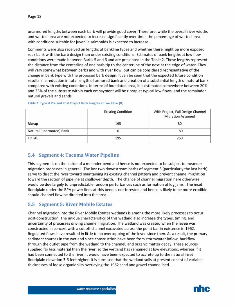
Comments were also received on lengths of bankline types and whether there might be more exposed rock bank with the barb design than under existing conditions. Estimates of bank lengths at low flow conditions were made between Barbs 5 and 6 and are presented in the Table 2. These lengths represent the distance from the centerline of one barb tip to the centerline of the next at the edge of water. They will vary somewhat between barbs and with river flow, but can be considered representative of the change in bank type with the proposed barb design. It can be seen that the expected future condition results in a reduction in total length of armored bank and creation of a substantial length of natural bank compared with existing conditions. In terms of inundated area, it is estimated somewhere between 20% and 35% of the substrate within each embayment will be riprap at typical low flows, and the remainder natural gravels and sands.
Table 2: Typical Pre and Post Project Bank Lengths at Low Flow (ft)
Existing Condition With Project, Full Design Channel Migration Assumed
Riprap 195 80
Natural (unarmored) Bank 0 180
TOTAL 195 260
5.4 Segment 4: Tacoma Water Pipeline This segment is on the inside of a meander bend and hence is not expected to be subject to meander migration processes in general. The last two downstream barbs of segment 3 (particularly the last barb) serve to direct the river toward maintaining its existing channel pattern and prevent channel migration toward the section of pipeline at shallower depth. The chance of channel migration here otherwise would be due largely to unpredictable random perturbances such as formation of log jams. The inset floodplain under the BPA power lines at this bend is not forested and hence is likely to be more erodible should channel flow be directed into the area.
5.5 Segment 5: River Mobile Estates Channel migration into the River Mobile Estates wetlands is among the more likely processes to occur post-construction. The unique characteristics of this wetland also increase the types, timing, and uncertainty of processes driving channel migration. The wetland was created when the levee was constructed in concert with a cut off channel excavated across the point bar in existence in 1962. Regulated flows have resulted in little to no overtopping of the levee since then. As a result, the primary sediment sources in the wetland since construction have been from stormwater inflow, backflow through the outlet pipe from the wetland to the channel, and organic matter decay. These sources supplied far less material than the river, so the wetland has remained at low elevations, whereas if it had been connected to the river, it would have been expected to accrete up to the natural inset floodplain elevation 3-6 feet higher. It is surmised that the wetland soils at present consist of variable thicknesses of loose organic silts overlaying the 1962 sand and gravel channel bed.
Page 19
water resource specialists
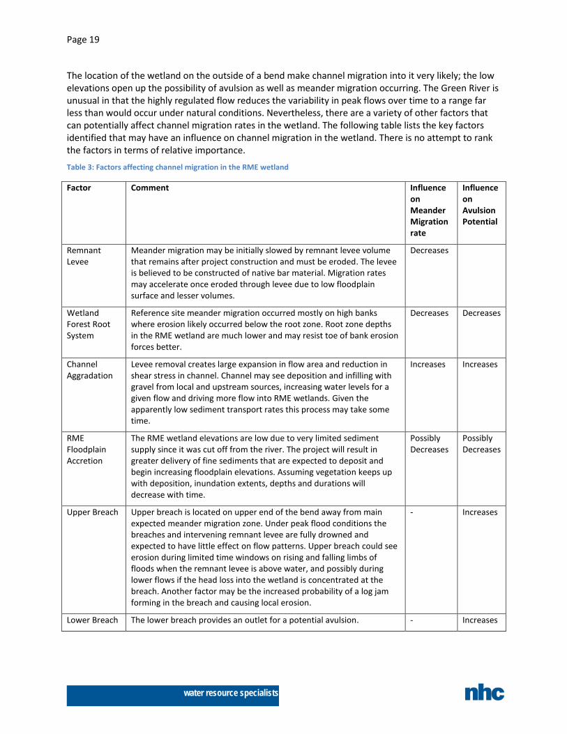
The location of the wetland on the outside of a bend make channel migration into it very likely; the low elevations open up the possibility of avulsion as well as meander migration occurring. The Green River is unusual in that the highly regulated flow reduces the variability in peak flows over time to a range far less than would occur under natural conditions. Nevertheless, there are a variety of other factors that can potentially affect channel migration rates in the wetland. The following table lists the key factors identified that may have an influence on channel migration in the wetland. There is no attempt to rank the factors in terms of relative importance.
Table 3: Factors affecting channel migration in the RME wetland
Factor Comment Influence on Meander Migration rate
Influence on Avulsion Potential
Remnant Levee
Meander migration may be initially slowed by remnant levee volume that remains after project construction and must be eroded. The levee is believed to be constructed of native bar material. Migration rates may accelerate once eroded through levee due to low floodplain surface and lesser volumes.
Decreases
Wetland Forest Root System
Reference site meander migration occurred mostly on high banks where erosion likely occurred below the root zone. Root zone depths in the RME wetland are much lower and may resist toe of bank erosion forces better.
Decreases Decreases
Channel Aggradation
Levee removal creates large expansion in flow area and reduction in shear stress in channel. Channel may see deposition and infilling with gravel from local and upstream sources, increasing water levels for a given flow and driving more flow into RME wetlands. Given the apparently low sediment transport rates this process may take some time.
Increases Increases
RME Floodplain Accretion
The RME wetland elevations are low due to very limited sediment supply since it was cut off from the river. The project will result in greater delivery of fine sediments that are expected to deposit and begin increasing floodplain elevations. Assuming vegetation keeps up with deposition, inundation extents, depths and durations will decrease with time.
Possibly Decreases
Possibly Decreases
Upper Breach Upper breach is located on upper end of the bend away from main expected meander migration zone. Under peak flood conditions the breaches and intervening remnant levee are fully drowned and expected to have little effect on flow patterns. Upper breach could see erosion during limited time windows on rising and falling limbs of floods when the remnant levee is above water, and possibly during lower flows if the head loss into the wetland is concentrated at the breach. Another factor may be the increased probability of a log jam forming in the breach and causing local erosion.
- Increases
Lower Breach The lower breach provides an outlet for a potential avulsion. - Increases
Page 20
water resource specialists
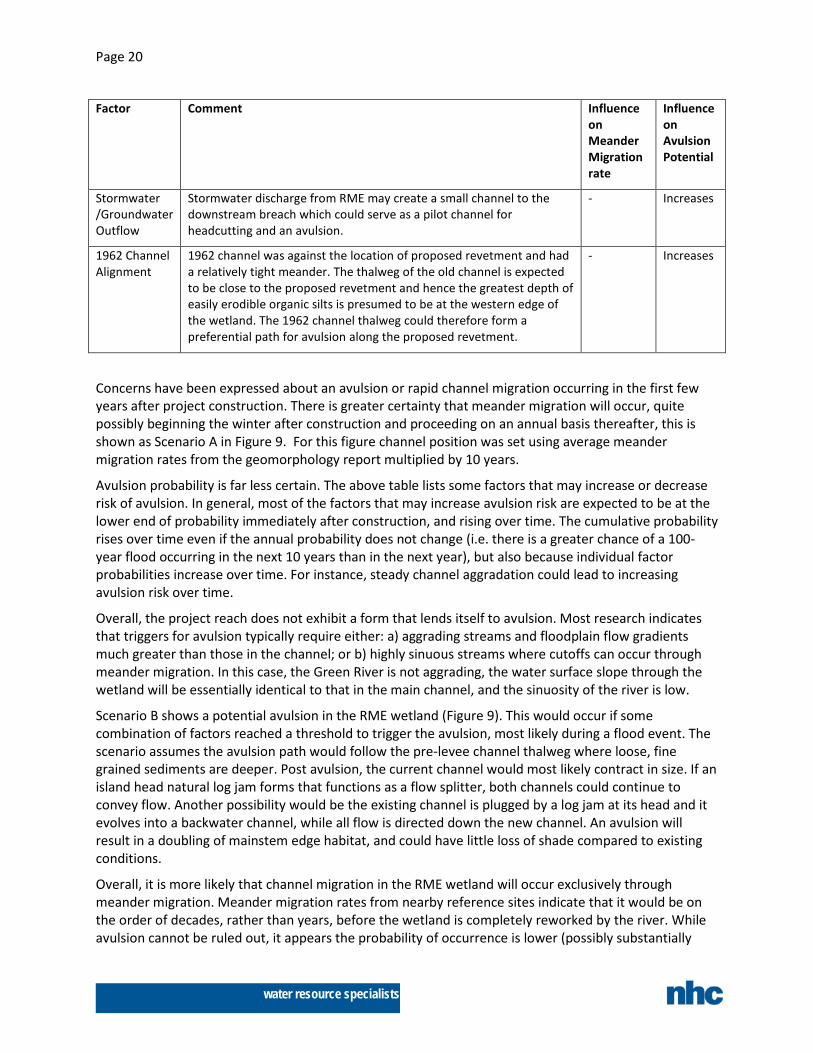
Factor Comment Influence on Meander Migration rate
Influence on Avulsion Potential
Stormwater /Groundwater Outflow
Stormwater discharge from RME may create a small channel to the downstream breach which could serve as a pilot channel for headcutting and an avulsion.
- Increases
1962 Channel Alignment
1962 channel was against the location of proposed revetment and had a relatively tight meander. The thalweg of the old channel is expected to be close to the proposed revetment and hence the greatest depth of easily erodible organic silts is presumed to be at the western edge of the wetland. The 1962 channel thalweg could therefore form a preferential path for avulsion along the proposed revetment.
- Increases
Concerns have been expressed about an avulsion or rapid channel migration occurring in the first few years after project construction. There is greater certainty that meander migration will occur, quite possibly beginning the winter after construction and proceeding on an annual basis thereafter, this is shown as Scenario A in Figure 9. For this figure channel position was set using average meander migration rates from the geomorphology report multiplied by 10 years.
Avulsion probability is far less certain. The above table lists some factors that may increase or decrease risk of avulsion. In general, most of the factors that may increase avulsion risk are expected to be at the lower end of probability immediately after construction, and rising over time. The cumulative probability rises over time even if the annual probability does not change (i.e. there is a greater chance of a 100-year flood occurring in the next 10 years than in the next year), but also because individual factor probabilities increase over time. For instance, steady channel aggradation could lead to increasing avulsion risk over time.
Overall, the project reach does not exhibit a form that lends itself to avulsion. Most research indicates that triggers for avulsion typically require either: a) aggrading streams and floodplain flow gradients much greater than those in the channel; or b) highly sinuous streams where cutoffs can occur through meander migration. In this case, the Green River is not aggrading, the water surface slope through the wetland will be essentially identical to that in the main channel, and the sinuosity of the river is low.
Scenario B shows a potential avulsion in the RME wetland (Figure 9). This would occur if some combination of factors reached a threshold to trigger the avulsion, most likely during a flood event. The scenario assumes the avulsion path would follow the pre-levee channel thalweg where loose, fine grained sediments are deeper. Post avulsion, the current channel would most likely contract in size. If an island head natural log jam forms that functions as a flow splitter, both channels could continue to convey flow. Another possibility would be the existing channel is plugged by a log jam at its head and it evolves into a backwater channel, while all flow is directed down the new channel. An avulsion will result in a doubling of mainstem edge habitat, and could have little loss of shade compared to existing conditions.
Overall, it is more likely that channel migration in the RME wetland will occur exclusively through meander migration. Meander migration rates from nearby reference sites indicate that it would be on the order of decades, rather than years, before the wetland is completely reworked by the river. While avulsion cannot be ruled out, it appears the probability of occurrence is lower (possibly substantially

Page 21
water resource specialists
lower) than meander migration and at its lowest immediately post construction, with increasing risk over time.
5.6 Segment 6: Downstream Reach Channel migration in segment 6 is expected to be mostly driven by adjustment to upstream migration in the River Mobile Estates wetland. Near term changes are therefore most likely at the upper end of the reach, tapering off as the river adjusts its form to transition back into its current alignment.

Figure 8: Inundation Area at 2000 cfs and Zones

Figure 9: Potential Future Vision