recommended preferred route option report - …...preliminary geotechnical investigation report...
TRANSCRIPT

Recommended Preferred Route Option Report Bolivia Hill Upgrade – Assessment of Route Options
August 2013 Cardno
Bolivia Hill Upgrade - Assessment of Route Options
APPENDIX I PRELIMINARY GEOTECHNICAL INVESTIGATION REPORT

Cardno (NSW/ACT) Pty Ltd trading as
Cardno Geotech Solutions
ABN 95 001 145 035
P.O Box 4224, Edgeworth 2285
Unit 4/5 Arunga Dr, Beresfield 2322
[P] 0249 494300
[F] 0249 660485
PRELIMINARY GEOTECHNICAL ASSESSMENT
BOLIVIA HILL UPGRADE, NEW ENGLAND HIGHWAY
ROUTE OPTIONS ASSESSMENT
ASHTONFIELD
Prepared for
Roads and Maritime Services
Prepared by
Cardno Geotech Solutions Pty Ltd
GS Ref: 1398-002/1
December 2012

Page i
Roads and Maritime Services Preliminary Geotechnical Assessment Proposed Bolivia Hill Upgrade, Route Options Ref GS1398-002/1, December 2012
Cardno Geotech Solutions Pty Ltd
Contents
1 INTRODUCTION ...............................................................................................................1
2 GEOTECHNICAL ASSESSMENT METHODS ..........................................................................2
2.1 DESKTOP STUDY ......................................................................................................2
2.2 FIELD MAPPING .......................................................................................................2
3 EXISTING INFRASTRUCTURE ............................................................................................2
3.1 NEW ENGLAND HIGHWAY ..........................................................................................3
3.1.1 CUTTINGS ......................................................................................................... 3
3.1.2 EMBANKMENTS ................................................................................................. 3
3.1.3 ROAD DRAINAGE................................................................................................ 6
3.2 MAIN NORTH RAILWAY LINE .......................................................................................6
3.2.1 CUTTINGS ......................................................................................................... 6
3.2.2 EMBANKMENTS ................................................................................................. 7
3.3 PYES CREEK ROAD ....................................................................................................7
4 SUMMARY OF FINDINGS .................................................................................................8
4.1 TOPOGRAPHY .........................................................................................................8
4.2 SURFACE DRAINAGE .................................................................................................8
4.3 GEOLOGY ..............................................................................................................9
4.3.1 GEOLOGICAL STRUCTURES/DEFECTS ....................................................................10
4.4 WEATHERING ....................................................................................................... 13
4.5 ROCK STRENGTH ESTIMATES ..................................................................................... 16
4.6 SOILS .................................................................................................................. 16
4.7 GROUNDWATER .................................................................................................... 16
4.8 PREVIOUS MINING ................................................................................................. 17
4.9 ACID ROCK DRAINAGE ............................................................................................. 17
4.10 STRESS RELIEF ....................................................................................................... 17
4.11 ACID SULPHATE SOILS ............................................................................................. 17
5 CONSTRUCTION MATERIALS AVAILABILITY .................................................................... 18
5.1 SITE EXCAVATIONS ................................................................................................. 18
5.2 LOCAL ROAD CONSTRUCTION MATERIALS SUPPLIERS ....................................................... 18
6 PRELIMINARY DESIGN RECOMMENDATIONS .................................................................. 19
6.1 CUTTINGS ............................................................................................................ 20
6.1.1 EXCAVATABILITY ..............................................................................................20
6.1.2 CUT SLOPE STABILITY AND DESIGN .......................................................................20
6.1.3 GROUNDWATER/CUT FLOOR CONDITIONS ............................................................22
6.2 EMBANKMENTS .................................................................................................... 22
6.2.1 FOUNDATION CONDITIONS AND SUBGRADE TREATMENT .........................................22
6.2.2 SUITABLE MATERIAL TYPES ................................................................................22
6.2.3 EMBANKMENT BATTER DESIGN...........................................................................22
6.2.4 ANTICIPATED SETTLEMENTS ...............................................................................23
6.3 REINFORCED SOIL WALLS ......................................................................................... 23
6.4 BRIDGES .............................................................................................................. 23

Page ii
Roads and Maritime Services Preliminary Geotechnical Assessment Proposed Bolivia Hill Upgrade, Route Options Ref GS1398-002/1, December 2012
Cardno Geotech Solutions Pty Ltd
6.5 PAVEMENTS ......................................................................................................... 24
7 ROUTE REALIGNMENT OPTION CONSTRAINTS ............................................................... 24
8 PROPOSED GEOTECHNICAL INVESTIGATION ................................................................... 25
9 LIMITATIONS ................................................................................................................. 26
REFERENCES ........................................................................................................................... 26
Cardno (NSW/ACT) Pty Ltd trading as
Cardno Geotech Solutions
ABN 95 001 145 035
P.O Box 4224, Edgeworth 2285
Unit 4/5 Arunga Dr, Beresfield 2322
[P] 0249 494300
[F] 0249 660485
Ref GS1398-002/1
21 December 2012
Roads and Maritime Services
C/- Cardno (NSW/ACT) Pty Ltd
PO Box 19
St Leonards 1590
Attention: John Rayment
PRELIMINARY GEOTECHNICAL ASSESSMENT
BOLIVIA HILL UPGRADE, NEW ENGLAND HIGHWAY ROUTE OPTIONS ASSESSMENT
1 INTRODUCTION
This report presents the results of a geotechnical desk top study and walkover survey for the
Bolivia Hill upgrade, route options assessment.
Cardno (NSW/ACT) have been commission by Roads and Maritime Services (RMS) to
complete a route evaluation study for the realignment of the New England Highway (NEH),
on the northern side of Bolivia Hill. The study area extends from Chainage 56400km to
Chainage 59400km along the NEH and covers an area of approximately 1.5km by 3km.
The existing NEH alignment has 2 lanes and traverses the side of a steep hill, which contains
some reasonably sharp corners and has an overall grade down to the north of 9%. It is
understood this section of the NEH has a poor crash history and the primary purpose of this
study is to define a minimum of 4 potential realignment options within the study area to
provide a safer road alignment with a proposed maximum grade of 6%. The realignment
options must include a minimum of 3 lanes, with 2 climbing (southbound) lanes and one
descending (northbound) lane.
The purpose of this geotechnical assessment was to develop an initial understanding of the
geology and geotechnical conditions within the study area and to provide preliminary
geotechnical design constraints to aid with route selection. In addition, a preliminary
assessment of local road construction material suppliers has been undertaken to assess
potential construction materials sources.

Page 2
Roads and Maritime Services Preliminary Geotechnical Assessment Proposed Bolivia Hill Upgrade, Route Options Ref GS1398-002/1, December 2012
Cardno Geotech Solutions Pty Ltd
Comments and recommendations are provided in this report on the site geology including
structural features, and preliminary design information including cut and fill batter slopes. A
geotechnical test plan for the proposed geotechnical investigation has not been included in
this report and will be provided following definition of the 4 preferred alignment options.
2 GEOTECHNICAL ASSESSMENT METHODS
2.1 DESKTOP STUDY
A desktop study was completed which comprised a review of:
Geological maps;
Topographical maps;
Acid sulphate soil maps; and
Geotechnical report prepared by RMS ‘HW9 Bolivia Hill Realignment, Preliminary
Desktop Study of Geology, Slope Stability, Geotechnical Design and Pavement
Design’, dated March 2012. The RMS report has been appended to this report for
reference purposes.
2.2 FIELD MAPPING
Field mapping was completed within the study area by a Principal Engineering Geologist
from Cardno Geotech Solutions (wholly owned subsidiary Cardno NSW/of ACT P/L) on 16 to
18 October 2012. In addition, meetings were held with two construction materials
contractors located within Tenterfield to discuss road construction materials availability.
The field mapping comprised observation of the following:
Geology exposed in rail and existing highway road cuttings;
Rail and road fill areas, particularly noting any current areas of instability;
Natural rock outcrop and hillside slopes within the study area; and
Drainage lines within the study area
Observations are shown on the attached site plans, Drawings 1A and 1B. Chainages shown
on the existing highway alignment on Drawings 1A and 1B were provided by RMS.
3 EXISTING INFRASTRUCTURE
Existing infrastructure within the study area includes:

Page 3
Roads and Maritime Services Preliminary Geotechnical Assessment Proposed Bolivia Hill Upgrade, Route Options Ref GS1398-002/1, December 2012
Cardno Geotech Solutions Pty Ltd
• A disused rail line, which was part of the Main North Railway Line, runs above the
highway and near the crest of a hill. The rail line runs sub-parallel to the highway
from the southern end of the study area to about Chainage 58400m where it veers
to the east and away from the highway,
The NEH extends from Chainage 56400m-59400m in the study area, and runs along
the side of a steep northwest facing hillside. The existing highway alignment is about
10m lower in elevation than the rail line at the southern end of the study area and
about 80m lower than the rail line at Chainage 58400m,
Pyes Creek Road joins the highway at Chainage 58900m and runs west.
A summary of conditions exposed in the road and rail alignments is provided below:
3.1 NEW ENGLAND HIGHWAY
The highway from the southern end of the study area to about Chainage 58300m, has been
constructed by cutting into the side of a northwest facing hillside and filling on the downhill
side. Cut/fill lines are expected to be within the carriageway in most areas.
3.1.1 CUTTINGS
The road contains steep cuttings (about 50˚-60˚) on the uphill (eastern side); the following
observations were made, noting that the chainages and cut height estimates are
approximate only;
• Chainage 56400km-57700km, cut heights up to 10m in distinctly weathered Granite
with close spaced jointing. Predominant joint set strikes north/south and were sub-vertical.
The cuts are about 60°, with isolated joint bounded rockfall primarily caused by tree root
jacking and weathering. Some slumping was observed in predominantly soil materials at the
edges of the cuts;
• Chainage 57700km-57900km, very high strength fresh Granite, jointing dipping out
of the cut at about 30° near the base of the cut at about Chainage 57750m. A Sub-vertical
joint surface running approximately north/south was also observed on the cut face. No sign
of slope instability was observed. The natural slope overlying this cutting is about 35°-40°
and exposes fresh Granite with minimal to no soil cover to near the crest of the slope;
• 57900km-58150km, distinctly weathered granite in a low height cutting (about 2m-
4m). Close spaced jointing with predominant joint set striking north/south. Some small
joint bounded block falls have occurred; and
• 58150km-59400km no outcrop, road alignment on shallow fill to on grade.
3.1.2 EMBANKMENTS
Fills occur on the downhill (western side) of the road and have been placed over steep
natural surface. Fill slope angles were measured using a clinometer to vary from about 37˚-
40˚.

Page 4
Roads and Maritime Services Preliminary Geotechnical Assessment Proposed Bolivia Hill Upgrade, Route Options Ref GS1398-002/1, December 2012
Cardno Geotech Solutions Pty Ltd
Fill height estimates are provided below, note the height estimates and chainages are
approximate. The fill height is the vertical distance between the fill toe and fill crest.
Chainage 57000m, 1m fill height increasing to 10m height at Ch57200m.
Ch57200m to about 57650m, 10m-15m high fill.
Ch57650m to Ch57750m, the fill height increases to an estimated 30m across a
major gully, (See Photograph 1).
57750m to 57900m, fill heights of around 10m-15m
57900m to 58300m, fill height reduces from 10m-15m to zero where the road is on
grade
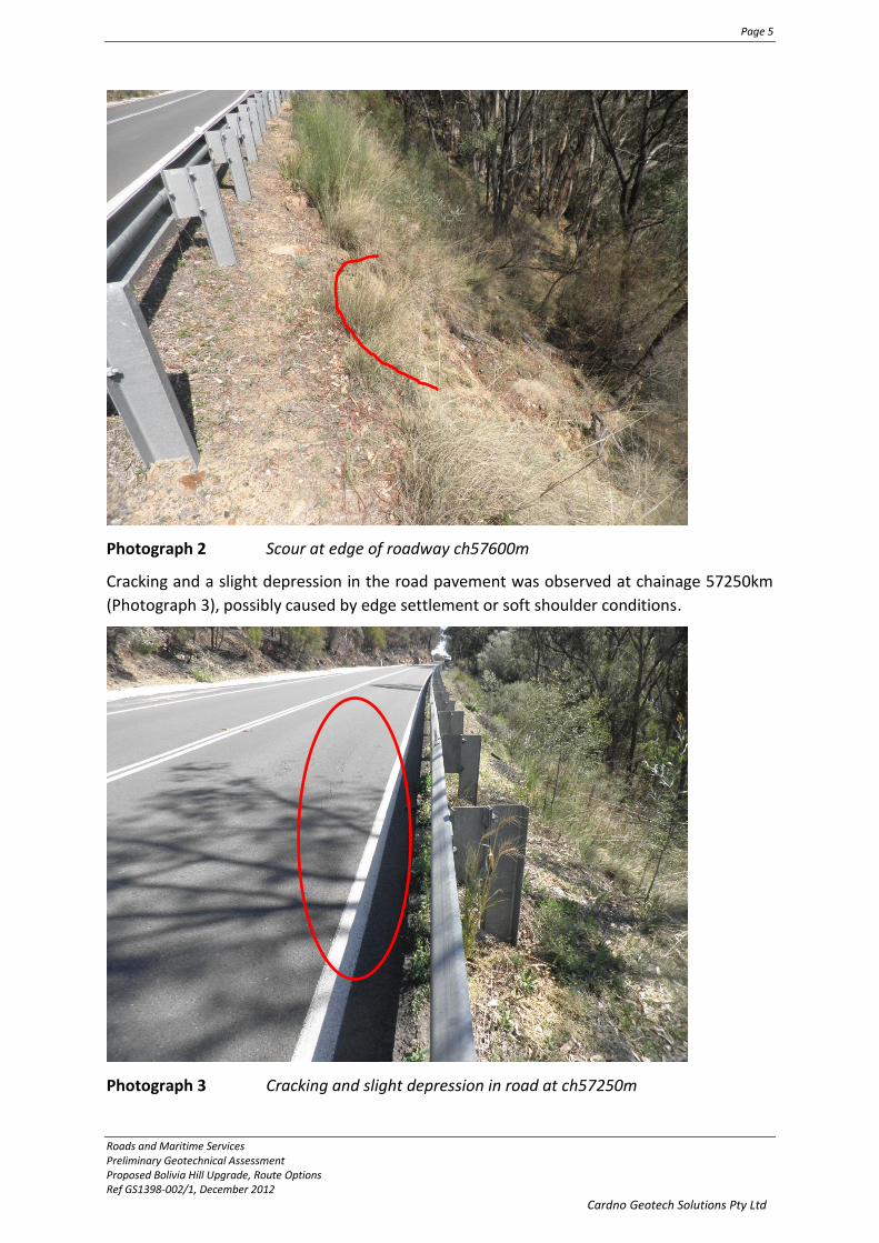
Photograph 1 High fill embankment across gully at Ch57650m to 57750m
No sign of large scale slope instability was observed on the fill slopes, some trees were
slightly bowed, suggesting possible shallow downhill creep movements. Some shallow and
small scale scouring was also observed near the road edge at Ch 57600km (Photograph 2).
Page 5
Roads and Maritime Services Preliminary Geotechnical Assessment Proposed Bolivia Hill Upgrade, Route Options Ref GS1398-002/1, December 2012
Cardno Geotech Solutions Pty Ltd
Photograph 2 Scour at edge of roadway ch57600m
Cracking and a slight depression in the road pavement was observed at chainage 57250km
(Photograph 3), possibly caused by edge settlement or soft shoulder conditions.
Photograph 3 Cracking and slight depression in road at ch57250m

Page 6
Roads and Maritime Services Preliminary Geotechnical Assessment Proposed Bolivia Hill Upgrade, Route Options Ref GS1398-002/1, December 2012
Cardno Geotech Solutions Pty Ltd
3.1.3 ROAD DRAINAGE
Surface drainage from uphill is collected in a concrete lined dish drain and directed to cross
drains which run below the pavement and discharge onto the fill slope. No drop structures
were evident; the cross drains discharge high on the embankment fills. The cross drains are
located between about Ch57100m and 58100m, spacing varies though is generally around
100m-200m.
3.2 MAIN NORTH RAILWAY LINE
A single track disused railway line, which once formed part of the Main North Railway Line,
runs above the highway from the southern end of the study area to about Ch. 58400m
where the rail line veers away and to the east of the highway. The rail line between Glen
Innes and Tenterfield is understood to have been constructed by Cobb and Co. and opened
in 1886.
The rail line has been constructed near the crest of a hill and contains a series of double
sided cuttings and embankments across drainage lines.
3.2.1 CUTTINGS
The rail cuttings expose granite rock and were generally around 70˚-80˚ and a maximum of
about 20m deep. Small diameter blast holes were observed at about 2m intervals through
the cuts indicating blasting was carried out during excavation.
A typical cut profile comprised about 1m of coarse clayey sand with occasional rounded
weathered granite corestones overlying around 1m of distinctly weathered granite then
fresh to slightly weathered coarse grained granite.
Occasional more weathered zones/seams were observed following defect/joint surfaces.
Minor instability in the form of small block falls was observed within the cuttings.

Page 7
Roads and Maritime Services Preliminary Geotechnical Assessment Proposed Bolivia Hill Upgrade, Route Options Ref GS1398-002/1, December 2012
Cardno Geotech Solutions Pty Ltd
Photograph 4 Rail Cutting, Uphill of Chainage 57000m
3.2.2 EMBANKMENTS
The rail embankments have generally been placed across gully areas with estimated
embankment heights of up to about 20m and side slopes ranging from 37˚ to 40˚. The
embankment side slopes in many areas were covered by granite boulders up to about 1m in
size. It is presumed the embankments were constructed using materials excavated from the
cuttings. The embankments are therefore likely to be comprised of slightly weathered-fresh
Granite rockfill material.
The embankment side slopes contained some trees which were bowed suggesting possible
downhill creep movements. No obvious sign of past or existing gross slope instability was
observed on the fill slopes, though RMS reports ‘small-medium sized slips are evident along
the batters as slip scars and areas of cleared or changed vegetation’.
The toe of the rail fill slopes occur around 20m-40m uphill of the NEH road cuttings.
3.3 PYES CREEK ROAD
Pyes Creek Road joins the NEH at Chainage 58900m and runs west. Within the study area
the road has been constructed over the flat lying ground within the foothills of Bolivia Hill.
No cuttings and only minor fills occur along the road.

Page 8
Roads and Maritime Services Preliminary Geotechnical Assessment Proposed Bolivia Hill Upgrade, Route Options Ref GS1398-002/1, December 2012
Cardno Geotech Solutions Pty Ltd
4 SUMMARY OF FINDINGS
4.1 TOPOGRAPHY
The study area can be divided into two separate areas, the southern area from Chainage
56400m to 58600m which is underlain by the ‘Bolivia Range Leucomonzogranite’, and the
northern area underlain by Dundee Rhyodacite (Refer Figure 1A and 1B for the inferred
geological contact).
The southern area comprises two prominent ridge lines with steep side slopes, containing
areas of sub-vertical to 60˚ Granite outcrop and soil covered slopes of up to about 20˚ to
25˚, containing scattered Granite boulders. The ridge lines are located east and west of the
current NEH alignment.
The ridge line west of the current highway alignment strikes NE/SW and has a maximum
elevation of around RL1040m within the study area. The ridge line east of the current
highway alignment strikes NNE/SSW and has a maximum elevation of around RL1000m
within the study area.
The northern part of the study area is reasonably flat lying and grass covered with no rock
outcrop.
4.2 SURFACE DRAINAGE
Surface drainage lines are shown on Figures 1A and 1B. The major drainage line runs NE/SW
on the western side of the NEH and is at an elevation of approximately RL940m at the
southern end of the subject area and falls to about RL820m towards the base of Bolivia Hill,
where it then meanders across flat lying terrain and crosses Pyes Creek Road about 400m
west of the highway.
The creek has gouged a deep (approximately 20m) steep sided gorge exposing fresh Granite
outcrop, approximately 200m west of the current road alignment, opposite chainages
57000m-57300m (refer Figure 1A). A second drainage line running sub-parallel to the main
creek occurs close to the western side of the NEH and is separated from the main creek by a
small ridge line. This creek joins the main drainage line opposite Chainage 57700m and
about 150m west of the highway.
Several drainage lines run off the two main ridge lines within the study area and connect
with the main (NE/SW) drainage line. At the time of inspection all drainage lines running off
the ridge lines were dry with only minor ponded water observed in some areas.
Brickyard Creek is also located at the northern end of the subject area within the flat lying
terrain and runs approximately NW/SE.

Page 9
Roads and Maritime Services Preliminary Geotechnical Assessment Proposed Bolivia Hill Upgrade, Route Options Ref GS1398-002/1, December 2012
Cardno Geotech Solutions Pty Ltd
4.3 GEOLOGY
Bolivia Hill is located within the New England Fold belt. Bolivia Hill is formed from an early
Triassic granitoid, the ‘Bolivia Range Leucomonzogranite’. Reference to air photos shows
major structural lineaments running in a NNE direction through the range.
The Geology maps show the Granite covering the southern, hilly part of the subject area up
to about Ch. 58100km on the NEH with the Dundee Rhyodacite over the northern end of the
study area. Our mapping suggested the contact may be closer to about Ch. 58600m.
The granite has a coarse crystalline structure comprising quartz, mica and feldspar and other
minor constituents.
Photograph 5 Fresh ‘Granite’ Rock from Rail Cutting
Rhyodacite (toscanite) is a fine-grained, extrusive, igneous rock characterized by an
adamellite mineral assemblage and composition. Most rhyodacites are porphyritic, with
quartz and plagioclase as common phenocryst types. The term ‘toscanite’ was used
originally by H. S. Washington in 1897 to describe rocks of rhyodacite composition from
Tuscany, Italy; this older term is now little used. Rhyodacites are erupted above subducted
plates and belong to the calcalkaline magma series.
No exposure of Rhyodacite was observed in the study area and it is inferred the Rhyodacite
may occur below the surface soil cover over the northern part of the study area within the
foothill region. The approximate ‘inferred’ contact is located at about Ch58600m on the
current alignment which is further north than shown on geology maps (Refer Figure 1B
attached).

Page 10
Roads and Maritime Services Preliminary Geotechnical Assessment Proposed Bolivia Hill Upgrade, Route Options Ref GS1398-002/1, December 2012
Cardno Geotech Solutions Pty Ltd
A 2m wide fresh-slightly weathered Basalt dyke was observed in rail and road cuttings and is
plotted on Figure 1A. The dyke has intruded along a north/south striking joint. Close
spaced jointing was observed either side of the dyke.
Photograph 6 Basalt dyke in road cut about ch57600m, note close spaced parallel
jointing striking north/south adjacent the dyke
The RMS report mentioned a borehole investigation for the bridge over Brickyard Creek,
which encountered sandy and clayey silts to 6m then a ‘diorite’ bedrock. RMS suggests that
assuming the rocktype was named correctly this may represent an igneous dyke.
4.3.1 GEOLOGICAL STRUCTURES/DEFECTS
A stereonet showing measured joint orientations gained from all road and rail cuttings is
shown below. Joint orientations were measured using a geological compass and are
approximate only.

Page 11
Roads and Maritime Services Preliminary Geotechnical Assessment Proposed Bolivia Hill Upgrade, Route Options Ref GS1398-002/1, December 2012
Cardno Geotech Solutions Pty Ltd
Figure 1 Stereonet Showing Contour of Poles to Joints
From the available data, 3 main joint sets were identified. All orientations are referenced to
magnetic north:
Table 1 Measured Joint Orientations
Joint Set Dip direction
(approximate range)
Dip (approximate
range)
Approximate
Average Dip/Dip
direction
1 270°-295° 65°-80° 72°/285°
2 335°-350° 80°-90° 88°/342°
3 215°-235° 78°-90° 85°/225°
The joints observed in existing road and rail cuttings were generally spaced around 0.2m-
2.0m.
A shallow joint (30˚/300˚) was observed daylighting at the base of cut slope at about
Ch57750m. The joint is inferred to be an exfoliation joint formed sub-parallel to the slope
surface. The joint surface appeared tight and contained no obvious staining or infill. No
sign of movement along the joint was observed.
The current most plausible explanation for exfoliation joints is that they are caused by large
compressive stresses parallel to the ground or outcrop surface leading to tensile cracking.
Joint spacing increases from a few centimeters near surface to a few metres with depth.

Page 12
Roads and Maritime Services Preliminary Geotechnical Assessment Proposed Bolivia Hill Upgrade, Route Options Ref GS1398-002/1, December 2012
Cardno Geotech Solutions Pty Ltd
No obvious sign of faulting or shearing was observed in surface outcrop. It is possible the
drainage line running to the west of the current alignment follows an existing shear or fault
zone. The drainage line follows the general NNE lineament observed in the Bolivia Hill
Granite.
Photograph 7 Joint Set 1 exposed in Rail Cutting, note the close joint spacing
Joint Set 1

Page 13
Roads and Maritime Services Preliminary Geotechnical Assessment Proposed Bolivia Hill Upgrade, Route Options Ref GS1398-002/1, December 2012
Cardno Geotech Solutions Pty Ltd
Photograph 8 Cutting at Ch57700m-57800m, Showing Low Angle ‘Exfoliation’ Joints,
Parallel to Slope Surface
4.4 WEATHERING
Weathering in Granite occurs by alteration of the minerals to clay, with the exception of
quartz which is resistant to weathering. Completely weathered Granite consists of a clayey
sand material, with the sand sized particles predominantly comprising quartz grains.
Weathering generally occurs preferentially along open/weathered joint surfaces
(Photograph 9), resulting in an uneven weathering profile.
Fresh-slightly weathered Granite outcrops occur along ridge lines and in some areas on the
sides of hills in the study area. Figures 1A and 1B show the areas where Granite rock is
outcropping. The rail cuttings predominantly expose slightly weathered-fresh Granite as
the cuttings occur towards the top of the hill. The NEH cuttings are on the side of the hill
and expose both distinctly weathered Granite (Photograph 10) and slightly weathered-fresh
Granite (Photograph 11). The depth of weathering in the cutting shown in Photograph 10 is
not known as weathered rock extends the full cutting height (about 10m).
The cuttings shown in Photographs 10 and 11 are separated by a steep natural gully. The
cutting in Photograph 11, north of this gully is below a natural slope that exposes rounded
fresh Granite outcrop to near the slope crest. The cutting in photograph 10, south of the
gully is located below a steep natural slope that exposes soil and scattered boulders.
A visual appraisal of rocktype exposed in the cuttings (road and rail) on both sides of the
gully suggest the same (or very similar) rocktype i.e. coarse crystalline Granite.
30˚/300˚ joints,
‘exfoliation joint’
Natural Outcrop
Cutting

Page 14
Roads and Maritime Services Preliminary Geotechnical Assessment Proposed Bolivia Hill Upgrade, Route Options Ref GS1398-002/1, December 2012
Cardno Geotech Solutions Pty Ltd
It is possible the variation in weathering of the rock exposed in the cuttings either side of
the gully may be due to variation in weathering processes, rather than a variation in
rocktype.
It is noted that the slope on the northern side of the gully from 57700m-57900m which
exposes slightly weathered-fresh Granite is parallel or sub-parallel to the major joint set,
which may affect the rate of weathering of this slope. The RMS report, however, suggests
the cutting to the north of the gully exposes ‘siliceous’ Granite which is more resistant to
weathering, to explain the variation in rock weathering either side of this gully. Sampling of
rock materials and completion of Petrographic or X-ray diffraction analysis would be
required to determine possible rock type composition variations.
Photograph 9 Example showing depth of weathering variation within rail line cut
through ridge line, with deeper weathering above zones of closer joint
spacing
Weathering Profile
Zones of Close Joint Spacing

Page 15
Roads and Maritime Services Preliminary Geotechnical Assessment Proposed Bolivia Hill Upgrade, Route Options Ref GS1398-002/1, December 2012
Cardno Geotech Solutions Pty Ltd
Photograph 10 Road cutting ch57500m-57600m, example of distinctly weathered
Granite on the side of a hill
Photograph 11 Slightly weathered-fresh granite cutting ch57800m into the side of hill
Joint set 1
Natural outcrop
Shallow exfoliation joint parallel
to slope surface
Cut

Page 16
Roads and Maritime Services Preliminary Geotechnical Assessment Proposed Bolivia Hill Upgrade, Route Options Ref GS1398-002/1, December 2012
Cardno Geotech Solutions Pty Ltd
Granite may also weather to form rounded fresh corestones within a more weathered
matrix. The corestones can be of a size ranging from about 0.5m diameter to many metres
in diameter. These conditions can cause difficulty with excavation and final trimming of cut
slopes, where high strength corestones project above the final cut profiles. Some corestone
development in a weathered matrix was observed in the railway cuttings, though depth of
weathering was minimal (generally around 1m-3m only). No corestones were observed in
the road cuttings.
4.5 ROCK STRENGTH ESTIMATES
Granite rock strength in the slightly weathered to fresh state would likely be very high
(about 60-200MPa, unconfined compressive strength). Where the Granite has weathered
to distinctly weathered, rock strength will reduce, and possibly be in the medium-high range
(about 6-60MPa, unconfined compressive strength). Intact rock strengths will be assessed
during the proposed geotechnical investigation program, in particular rock strength
variations with depth and weathering.
4.6 SOILS
Soil materials likely to be encountered within the study area include:
Granite areas (hilly terrain southern part of study area): Thin mantle of
slopewash/colluvium (possibly 1m-2m depth) of sandy soil predominantly
comprising quartz grains with variable clay and gravel content over residual
soil/completely weathered granite possibly around 1m thick. Soils are likely to be
well drained.
Rhyodacite area (flatter terrain northern part of study area), comprising two soil
types as follows:
1. Residual soils possibly comprising sandy/clayey soils to around 5m depth (not
known, estimate only)
2. Alluvial soils along and adjacent existing drainage lines possibly comprising
sandy/silty soils and gravel bands, depths to around 5m-10m, based on the RMS
report [2] discussing previous drilling near the bridge over Brickyard Creek. The RMS
report stated: ‘Boreholes drilled for a bridge reconstruction project in 1982 show
diorite bedrock at 6m below sandy and clayey silts’.
4.7 GROUNDWATER
Subsurface groundwater conditions are not known at this stage. The steep topography and
generally highly jointed nature of the Granite observed in exposure would suggest
groundwater levels may be low through the majority of the subject area, possibly rising up
from the creek lines at a shallow angle through the hills. The presence of perched aquifers
overlying less jointed Granite and near surface shallow aquifers along the drainage lines is
possible.

Page 17
Roads and Maritime Services Preliminary Geotechnical Assessment Proposed Bolivia Hill Upgrade, Route Options Ref GS1398-002/1, December 2012
Cardno Geotech Solutions Pty Ltd
4.8 PREVIOUS MINING
It is understood that gold, tin, silver, high quality silica and arsenic were previously mined in
the region. No obvious signs of previous mining activities were observed during this
inspection. The RMS report [2] indicates:
‘Many small unmapped workings were observed on the ridgeline to the east of the current
alignment, and a vertical shaft accessing a 40cm quartz vein hosting minor quantities of
sphalerite and traces of chalcopyrite in the adjacent valley to the west of the current
alignment’.
4.9 ACID ROCK DRAINAGE
Acid drainage requires the presence of sulfide minerals (sulfidic ores) in rock, particularly
iron sulfide or pyrite. These can form within veins e.g. quartz within the Granite rock. No
obvious veining was observed within outcrop in the study area. Acid rock drainage is
primarily associated with coal mining, however can occur in any metaliferous mine.
It is noted, however, that RMS report indicates past mining activities accessing quartz veins.
Therefore, it is possible that some acid producing rock will be encountered in proposed
excavations.
Sampling and laboratory testing will be required to determine the acid producing potential
of the rock material.
4.10 STRESS RELIEF
Stress relief effects caused by high horizontal stresses and rapid unloading due to
excavation of cuttings have the potential to destabilize cut faces and heaving in cut floors.
Movement due to stress relief in cuttings generally occurs along low strength bands that are
either horizontal or with a dip component out of the face, and typically occur in stratified
strata, such as sedimentary rock.
Possible conduits for stress relief movement in cut faces or cut floors within the study area
include shallow dipping exfoliation joints and/or fault/sheared zones. The expected high
frictional resistance along exfoliation joint surfaces may restrict or prevent movement due
to stress relief, however if shallow dipping joint surfaces are located close to the cut floor it
is possible stress relief may induce buckling and heaving of thin sheets of rock.
The influence of any fault/shear zones cannot be anticipated at this stage, except for stating
that the current drainage line running NE/SW to the west of the current highway alignment
through the Granite area could possibly be following a faulted/sheared zone.
4.11 ACID SULPHATE SOILS
Acid sulphate soils are those which contain iron sulphides and when exposed to air after
being disturbed produce sulfuric acid caused by oxidation of the sulphides. Acid sulphate

Page 18
Roads and Maritime Services Preliminary Geotechnical Assessment Proposed Bolivia Hill Upgrade, Route Options Ref GS1398-002/1, December 2012
Cardno Geotech Solutions Pty Ltd
soils are typically found in mangroves, salt marshes, floodplains, swamps, wetlands,
estuaries, and brackish or tidal lakes, particularly in low-lying coastal areas.
Reference to the Australian Soil Resource Information System (ASRIS) website, shows the
study area to be located within an area defined as C4 Extremely Low Probability/Very Low
Confidence. Less than 1km north of Brickyard Creek, the map shows B4 Low
Probability/Very Low Confidence of acid sulphate soils. The study area is not expected to
contain acid sulphate soils.
5 CONSTRUCTION MATERIALS AVAILABILITY
5.1 SITE EXCAVATIONS
From our site observations to date there are potentially 3 road construction material types
available on-site.
Soil and completely weathered Granite: This material may be suitable for use as
earthfill, though quantities are expected to be very low.
Distinctly weathered Granite materials (e.g. material exposed in the road cutting at
Ch. 57500m, Photograph 10) are likely to be suitable for use as earthfill, reinforced
soil wall backfill, upper zone of formation and possibly select. Crushing and/or
breakdown of oversize will be required to obtain desired materials grading.
Slightly weathered and fresh Granite is likely to be suitable as rock fill material,
bridging, drainage material, and select layers. Crushing will be required to obtain the
desired material grading, with the potential for production of other pavement
materials subject to laboratory evaluation.
The use of a blend of rockfill and earthfill in embankment construction should be avoided.
An assessment of likely quantities of site won construction materials can be made following
a geotechnical subsurface investigation and laboratory testing program. The laboratory
testing must consider specified materials requirements as outlined in RTA QA Specification
R44.
5.2 LOCAL ROAD CONSTRUCTION MATERIALS SUPPLIERS
In addition to site won materials, alternate road construction materials suppliers are
available. The following contractors were visited:

Page 19
Roads and Maritime Services Preliminary Geotechnical Assessment Proposed Bolivia Hill Upgrade, Route Options Ref GS1398-002/1, December 2012
Cardno Geotech Solutions Pty Ltd
Daryl McCarthy Constructions P/L (DMC)-discussion was held with Daryl McCarthy.
DMC operate a crushing plant with 2 crushers, 10km north of Tenterfield on the
NEH. Material for crushing is primarily sourced from a quarry about 32km west of
Tenterfield. The rock type in the quarry is Trachyte. Materials able to be produced
at the crushing plant include select fill, DGB20, DGS, sealing aggregates and concrete
aggregates. The DGB product is produced using a blend of crushed product and a
natural ridge gravel (weathered granite).
They have a history of supplying road construction materials throughout the region
and are well known to RMS.
Townes Contracting Pty Ltd (TC)-discussion was held with Daniel Townes and Stan
Hickey. TC is located within Tenterfield and operates out of numerous local quarries.
Previous upgrades around Bolivia Hill used material sourced from a weathered
Granite Quarry (Hickey’s Pit), which is located south of Bolivia Hill and about 1km
south of McClifties Road. The pit is currently closed, however, could be re-opened.
Inspection of the pit revealed excavation of the weathered Granite has occurred to a
reasonably hard base, i.e. less weathered Granite. Subsurface investigations would
be required to assess potential remaining volumes and material types in Hickey’s Pit.
Hickey’s Pit has previously supplied select material, RSW backfill and general fill.
Pavement materials have been produced previously though required blending with
crushed product to achieve desired grading.
TC also operate a NATA registered laboratory in Tenterfield which is able to do
basic materials quality testing, Grading’s, PI’s, CBR’s etc. Previous test results on
materials from Hickeys Pit are held by TC.
It is also understood that Wayne McCarthy operates a quarry on the north side of
Bolivia Hill along Castlecrag Rd. The pit was not inspected and no contact has been
made at this stage with Wayne.
6 PRELIMINARY DESIGN RECOMMENDATIONS
Geotechnical design issues for the cuttings include:
Excavatability;
Cut stability including recommendations for slope design;
Acid rock drainage; and
Groundwater/cut floor conditions.
Geotechnical issues for the embankments include:
Key in detail into steep slopes including natural slopes and existing fill embankments
for the NEH;
Suitable material types for earthfill or rockfill;

Page 20
Roads and Maritime Services Preliminary Geotechnical Assessment Proposed Bolivia Hill Upgrade, Route Options Ref GS1398-002/1, December 2012
Cardno Geotech Solutions Pty Ltd
Embankment batter design;
Foundation conditions and subgrade treatment; and
Anticipated settlements
The recommendations provided below are preliminary only and subject to review
following completion of the proposed geotechnical investigation.
6.1 CUTTINGS
6.1.1 EXCAVATABILITY
Excavation by heavy ripping should be possible within the weathered zone. Based on
exposure observed to date, the depth of weathering in Granite areas is expected to vary
considerably throughout the study area. As a preliminary estimate, the following depths of
weathering should be assumed:
Ridge lines and area of existing outcrop; 0m-5m, with undulating weathering
profile
Hillside slopes with no outcrop Around 10m-20m (to be confirmed by
future geotechnical investigations)
Within fresh rock, blasting is expected to be required.
6.1.2 CUT SLOPE STABILITY AND DESIGN
Cut slope instability may be encountered from the following sources:
Existing road and rail fills: Slip circle failure caused by oversteep or undercut slopes
and/or saturation;
Loose boulders or outcrop on steep slopes above the NEH, can be destabilised by
undercutting or vibration during excavation of adjacent cuttings;
Completely and extremely weathered Granite and soil: Slip circle failures and/or
translational sliding on the underlying less weathered rock interface. The depth of
this material on the hill side slopes within the study area is expected to be minimal;
and
Distinctly weathered-fresh Granite: Joint controlled slide/wedge/toppling failure as
discussed below:
The orientation of joint surfaces relative to the cut face orientation and slope angle,
together with the friction angle along the joint surfaces and groundwater conditions will
control the stability of cut slopes within distinctly weathered-fresh Granite.
Joint sets 1 to 3, mapped in the rail and road cuttings are generally steeply dipping and any
slope shallower than about 0.5H:1V is unlikely to undercut these defects, therefore
slide/wedge failures along these defects would be unlikely if slopes are designed at 0.5H:1V
or shallower.

Page 21
Roads and Maritime Services Preliminary Geotechnical Assessment Proposed Bolivia Hill Upgrade, Route Options Ref GS1398-002/1, December 2012
Cardno Geotech Solutions Pty Ltd
Toppling failures are possible where the steep joint surfaces dip into cut slopes of about
0.5H:1V or steeper, and are more likely where they intersect a shallow dipping joint which
daylights on the slope surface. Toppling failures will be more likely on cut slopes that run
parallel or within about 20° of the strike of the main joint set (joint set 1) identified from
mapping.
Shallow dipping (~30°) exfoliation joints have been observed in the road cutting into the side
of the hill at about Ch 57750m within slightly weathered-fresh Granite. These joints could
provide a low angle surfaces to initiate toppling.
Wedge/slide failures are possible along these low angle joints where the joint dip exceeds
the friction angle of the joint plane. It would be expected where Granite is in a slightlly
weathered-fresh state, the friction angle along these defects will be high which would
reduce the likelihood of slide/wedge failures in this material.
The following preliminary cut slope design is recommended:
2H:1V batters, maximum 10m high with 4.5m bench where cuttings occur within
existing road and/or rail fill materials;
2H:1V batters, maximum 10m high where the cut surface lies within 20m of the
natural ground surface. Bench width minimum 4.5m. Steeper slopes maybe
possible within this zone subject to specific mapping and geotechnical investigation
data;
Where the cut surface is greater than 20m below ground surface, 0.5H:1V batters,
maximum batter height 7m with minimum 4.5m wide bench . Some minor
shotcteting and isolated rock bolts may be required to cover any sheared or more
weathered zones and to secure any potentially ‘loose’ blocks. Rock bolting may also
be required on slopes that strike within about 20° of Joint Set 1, to reduce toppling
risk. These batters should also be pre-split. Presplitting must consider the guidelines
provided in Reference 1, Section 4.5.2.
Additional recommendations include:
(a) A rock catch fence must be provided on the lowest bench in cuttings where the
batter above the lowest bench is steeper than 1.5H:1V.
(b) Except for transitions at the ends of cuttings, the slopes of cutting batters must not
lie between 0.75:1 H:V and 1.5:1 H:V.
(c) Cutting batters must be laid back and curved at the ends, for a minimum 50 m in
length, to reflect the influence of the subsurface profile and to blend in with
adjacent slopes.
(d) Cut batters designed 2H:1V or shallower should be topsoiled and vegetated to
reduce the risk of scour

Page 22
Roads and Maritime Services Preliminary Geotechnical Assessment Proposed Bolivia Hill Upgrade, Route Options Ref GS1398-002/1, December 2012
Cardno Geotech Solutions Pty Ltd
6.1.3 GROUNDWATER/CUT FLOOR CONDITIONS
Groundwater tables may be intercepted by the proposed cuttings. Overall, it could be
expected that the regional groundwater table will have been drawn down in the hill areas,
daylighting at or slightly below the valley floors and rising at a shallow angle within the hill
areas.
Boreholes and piezometers are recommended for the geotechnical investigations which
should assist in identifying groundwater surface profiles. Drainage blankets may be
required in any proposed deep cuttings.
6.2 EMBANKMENTS
6.2.1 FOUNDATION CONDITIONS AND SUBGRADE TREATMENT
Foundation conditions will vary across the site. Overall, it is expected that any
embankments within the hilly terrain where Granite is exposed will require stripping of
vegetation, topsoil and any sandy soil material to expose a weathered rock material. Depths
of stripping are expected to be no more than 1m in most areas. The topsoil may be
stockpiled on site and used for later topsoiling of embankment or cut slopes designed 2H:
1V or shallower.
In the flatter terrain over the north end of the study area, removal of vegetation and topsoil
will be required to expose a clayey sandy soil subgrade. At this stage, use of bridging layers,
geo-reinforcement and/or stabilisation is not expected to be required, however may be
dependent on climatic conditions prior to and during construction.
6.2.2 SUITABLE MATERIAL TYPES
Earthfill or rockfill may be used to construct the embankments. A hybrid embankment using
a combination of earthfill and rockfill should be avoided.
Earthfill embankments by definition are described in RTA QA Specification R44, Section
5.1.1. Rockfill embankments are described in RTA QA Specification R44, Section 5.1.2.
It is expected that a large proportion of excavated material could be used as rockfill. R44
requires a maximum size of 350mm, crushing and screening of excavated materials will be
required to produce suitable rockfill.
6.2.3 EMBANKMENT BATTER DESIGN
Embankment batters constructed using earthfill material should be designed no steeper
than 2H: 1V with 4.0m wide benches at 10m vertical height intervals. Topsoiling and
vegetation of 2H: 1V embankment batters will be required to reduce potential erosion.
Embankment batters constructed using rockfill may be designed assuming a maximum side
slope angle of 40°, no benches are required. The stability of rockfill embankments should be
assessed in detail prior to finalising side slope designs.

Page 23
Roads and Maritime Services Preliminary Geotechnical Assessment Proposed Bolivia Hill Upgrade, Route Options Ref GS1398-002/1, December 2012
Cardno Geotech Solutions Pty Ltd
Rockfill batters may be preferred to reduce the footprint of the proposed embankments. It
is expected that the majority of excavated material on site will comply with rockfill
specification in R44.
6.2.4 ANTICIPATED SETTLEMENTS
Embankment settlements, where they are constructed over weathered rock subgrade will
be primarily due to the self-weight of the fill. Embankment settlements where they are
constructed over soil materials within the northern foothills of the Bolivia Range may have a
component of settlement provided by the underlying natural soils.
For preliminary estimation purposes it could be assumed the following settlements may
occur:
Earthfill embankments (1) approximately 0.25% of the fill height
Rockfill embankments (1) approximately 0.1% of the fill height
Settlement of foundation soils Prediction will require specific geotechnical
investigation and laboratory analysis.
(1) Assumed constructed in accordance R44 guidelines.
6.3 REINFORCED SOIL WALLS
The use of reinforced soil walls (RSW’s) may be considered in embankment areas traversing
steep terrain to reduce embankment footprints. Material used for RSW backfill must
comply with RTA QA Specification R57.
This material could be developed on-site using excavated material from cuttings and on-site
crushing and screening. Alternatively materials could be sourced from local quarries.
RSW’s must be subject to detailed geotechnical global stability analyses.
6.4 BRIDGES
If bridges are required, design of bridge footings should consider the following:
Selection of appropriate footing design parameters should be based on detailed
geotechnical investigations at the proposed footing locations;
Caution will be required not to found footings on ‘corestones’ within a more
weathered matrix, on-site inspection and appropriate geotechnical investigations
will be required;
Excavation for piers within slightly weathered-fresh Granite or Rhyodacite will be
extremely difficult and likely penetration depths will be minimal. Piers may
therefore be designed predominantly for end bearing. Allowable end bearing
pressures in the slightly weathered-fresh Granite and Rhyodacite are likely to be
high;

Page 24
Roads and Maritime Services Preliminary Geotechnical Assessment Proposed Bolivia Hill Upgrade, Route Options Ref GS1398-002/1, December 2012
Cardno Geotech Solutions Pty Ltd
Bored piles or pad footings are likely to be the most suitable footing types. The
possibility of collapsing ground conditions and groundwater inflows should be
considered when determining a suitable footing type adjacent drainage lines, driven
piles maybe more suitable in these areas.
6.5 PAVEMENTS
A preliminary pavement design has been prepared by RMS in their report. The RMS report
has been appended for reference purposes.
7 ROUTE REALIGNMENT OPTION CONSTRAINTS
Currently 9 route realignment options have been prepared by Cardno. They involve
realignments to the west and east of the existing highway alignment and comprise cut/fill
earthworks through the southern portion of the alignment with maximum cut depths of
around 100m and fills to around 70m height. Fill embankments are proposed over the
flatter northern part of the alignment within the foothill region grading down to rejoin the
existing alignment.
A detailed review of each option is beyond the scope of this report. We have provided
below a list of potential issues to be considered when selecting preferred options.
(a) Embankment fills constructed along existing drainage lines will require diversion of
these drainage lines. It is recommended that these alignments be avoided;
(b) Options that show an embankment over Pyes Creek Road will require either a
diversion of Pyes Creek road or an overpass bridge with spill through abutments or
reinforced earth walls;
(c) Excavation of cuttings will generally require blasting, with exceptions being
excavations into the side of hills where there is currently no Granite outcrop. Heavy
ripping may be possible to depths of around 10m-20m below ground surface in
these areas, though should be assessed by future geotechnical investigations;
(d) Where the toe of embankments are located near the base of steep hillsides, control
of upslope surface water flow will be required to prevent scour of earthfill
embankment toes, possibly combined with use of scour protection, such as
placement of coarse rock over embankment toe areas.
(e) High embankment fills should be avoided due to long term settlement issues and in
particular differential settlements where the embankments are constructed over
high relief terrain;
(f) Embankments constructed over high relief terrain such as the deeply incised gorge
west of the NEH at the south end of the study area should be avoided, due to the
difficulty with achieving compaction adjacent steep walled rock outcrop and
potential for differential settlements;
Page 25
Roads and Maritime Services Preliminary Geotechnical Assessment Proposed Bolivia Hill Upgrade, Route Options Ref GS1398-002/1, December 2012
Cardno Geotech Solutions Pty Ltd
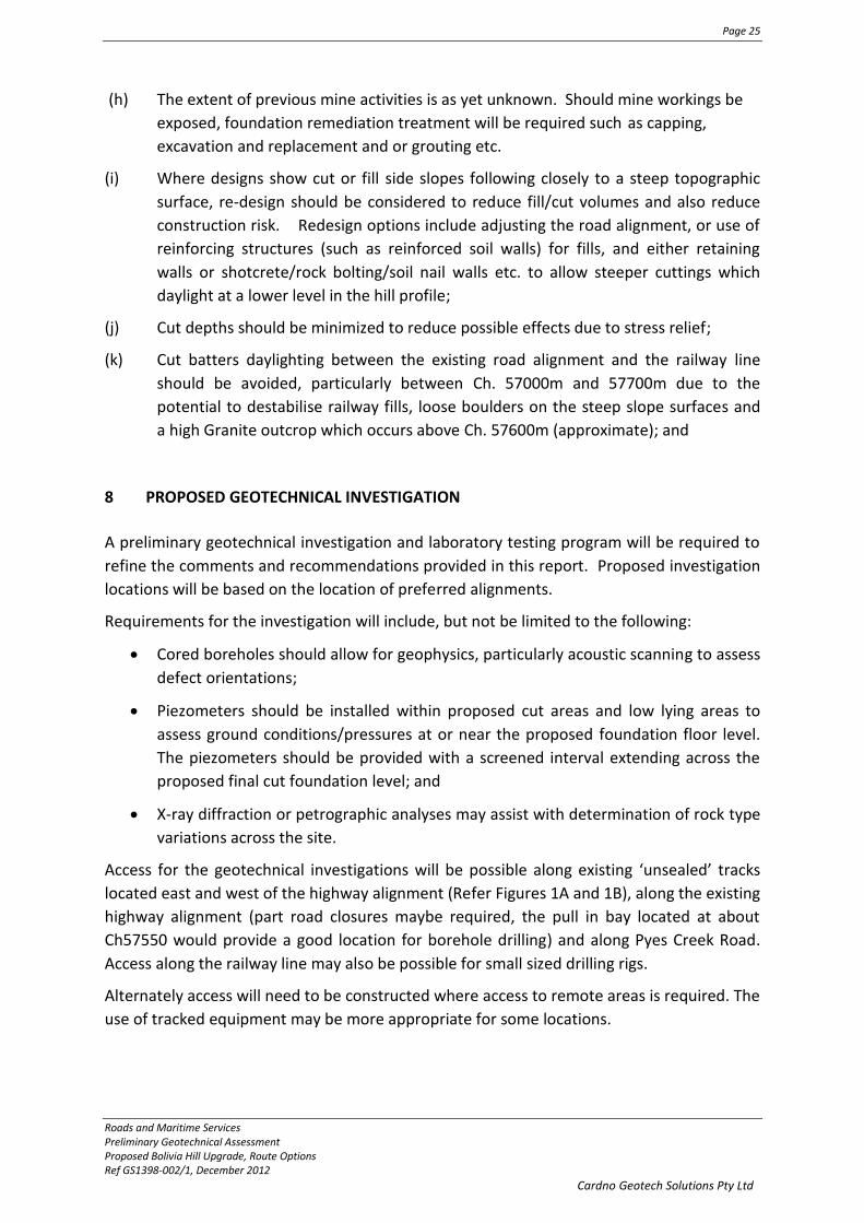
(h) The extent of previous mine activities is as yet unknown. Should mine workings be
exposed, foundation remediation treatment will be required such as capping,
excavation and replacement and or grouting etc.
(i) Where designs show cut or fill side slopes following closely to a steep topographic
surface, re-design should be considered to reduce fill/cut volumes and also reduce
construction risk. Redesign options include adjusting the road alignment, or use of
reinforcing structures (such as reinforced soil walls) for fills, and either retaining
walls or shotcrete/rock bolting/soil nail walls etc. to allow steeper cuttings which
daylight at a lower level in the hill profile;
(j) Cut depths should be minimized to reduce possible effects due to stress relief;
(k) Cut batters daylighting between the existing road alignment and the railway line
should be avoided, particularly between Ch. 57000m and 57700m due to the
potential to destabilise railway fills, loose boulders on the steep slope surfaces and
a high Granite outcrop which occurs above Ch. 57600m (approximate); and
8 PROPOSED GEOTECHNICAL INVESTIGATION
A preliminary geotechnical investigation and laboratory testing program will be required to
refine the comments and recommendations provided in this report. Proposed investigation
locations will be based on the location of preferred alignments.
Requirements for the investigation will include, but not be limited to the following:
Cored boreholes should allow for geophysics, particularly acoustic scanning to assess
defect orientations;
Piezometers should be installed within proposed cut areas and low lying areas to
assess ground conditions/pressures at or near the proposed foundation floor level.
The piezometers should be provided with a screened interval extending across the
proposed final cut foundation level; and
X-ray diffraction or petrographic analyses may assist with determination of rock type
variations across the site.
Access for the geotechnical investigations will be possible along existing ‘unsealed’ tracks
located east and west of the highway alignment (Refer Figures 1A and 1B), along the existing
highway alignment (part road closures maybe required, the pull in bay located at about
Ch57550 would provide a good location for borehole drilling) and along Pyes Creek Road.
Access along the railway line may also be possible for small sized drilling rigs.
Alternately access will need to be constructed where access to remote areas is required. The
use of tracked equipment may be more appropriate for some locations.

Page 26
Roads and Maritime Services Preliminary Geotechnical Assessment Proposed Bolivia Hill Upgrade, Route Options Ref GS1398-002/1, December 2012
Cardno Geotech Solutions Pty Ltd
9 LIMITATIONS
Cardno Geotech Solutions (CGS) have performed consulting services for this project in
general accordance with current professional and industry standards.
Cardno Geotech Solutions, or any other reputable consultant, cannot provide unqualified
warranties nor does it assume any liability for the site conditions not observed or accessible
during this assessment. Site conditions may also change subsequent to the assessment due
to ongoing use.
This report and associated documentation was undertaken for the specific purpose
described in the report and should not be relied on for other purposes. This report was
prepared solely for the use by Cardno and RMS and any reliance assumed by other parties
on this report shall be at such parties own risk.
Yours Faithfully,
CARDNO GEOTECH SOLUTIONS PTY LTD
Paul Lambert James Young
Principal Engineering Geologist Business Unit Manager- Director
REFERENCES
[1] Transport Roads and Maritime Services QA Specification R44 Earthworks, edition
3/revision 15, October 2011.
[2] RMS Report ‘HW9 Bolivia Hill Realignment, Preliminary Desktop Study of Geology,
Slope Stability, Geotechnical Design and Pavement Design’, dated March 2012
Attachments
Explanatory Notes
Figures 1A and 1B
RMS report

5800
0
5790
0
5780
0
5770
05760
05750
0
5740
0
5730
0
5720
0
5710
0
5700
0
5690
0
5680
0
5670
0
5660
0
5650
0
5640
0
83//751498
183//726317
7010//94920
86//751498
7009//94920 86//751498
165//1054742
87//751498NEW ENGLAND HIGHWAY
CH ILE FIRETRAIL
PATAGONIATRAIL
BRAZIL FIRETRAIL960
940
980
920
900
880
1000
1020
860840
1040
1060
10801100
820
980
860
®0 50 100 150 200
Metres
LegendStudy AreaCadastreChainagesRailway LineNew England HighwayRoads10m Topographic ContoursDrainage Lines
Geology:Bolivia Range LeucomonzograniteDundee Rhyodacite
Map Produced by Cardno NSW/ACT Pty Ltd (2812)Date: 2012-10-09
Coordinate System: GDA 1994 MGA Zone 56Project: NA89913018
Map: G1003_GeologyMapA.mxd 01Data Sources: NSW Land and Property Information (LPI)
HW9Bolivia Hill UpgradeGEOLOGY, SOILS AND DRAINAGE
FIGURE 1A
Scale at A31:6,000
Note: Soils throughout the study area are Cb30 - Rugged granitic areas with rock walls and tors (CSIRO)
NEW ENGLAND HIGHWAY
COLUMBIA FIRETRAILCHILE FIRETRAIL

5940
0
5930
0
5920
0
5910
0
5900
0
5890
0
5880
0
5870
0
5860
0
5850
0
5840
0
5830
0
5820
0
5810
0
5800
0
5790
0
5780
0
62//751498
7015//1065780
1//880845
63//751498
9//853518
6//8535188//853518
62//751498
7//853518
NEW ENGLAND HIGHWAY
PYES
CREEK
ROAD
PATAGONIA TRAIL
820
840
860
880
900
920940
960
800
920
BR
ICK
YAR
D C
RE
EK
®0 50 100 150 200
Metres
LegendStudy AreaCadastreChainagesRailway LineNew England HighwayRoads10m Topographic ContoursDrainage Lines
Geology:Bolivia Range LeucomonzograniteDundee Rhyodacite
Map Produced by Cardno NSW/ACT Pty Ltd (2812)Date: 2012-10-09
Coordinate System: GDA 1994 MGA Zone 56Project: NA89913018
Map: G1003_GeologyMapA.mxd 01Data Sources: NSW Land and Property Information (LPI)
HW9Bolivia Hill UpgradeGEOLOGY, SOILS AND DRAINAGE
FIGURE 1B
Scale at A31:6,000
Note: Soils throughout the study area are Cb30 - Rugged granitic areas with rock walls and tors (CSIRO)
NEW ENGLAND HIGHWAY
COLUMBIA FIRETRAILCHILE FIRETRAIL

Subsurface investigation may be conducted by one or a combination of the following methods.
Method
Test Pitting: excavation/trench
BH Backhoe bucket
EX Excavator bucket
X Existing excavation
Natural Exposure: existing natural rock or soil exposure
Manual drilling: hand operated tools
HA Hand Auger
Continuous sample drilling
PT Push tube
Hammer drilling
AH Air hammer
AT Air track
Spiral flight auger drilling
AS Large diameter short spiral auger
AD/V Continuous spiral flight auger: V-Bit
AD/T Continuous spiral flight auger: TC-Bit
Rotary non-core drilling
WS Washbore (mud drilling)
RR Rock roller
Rotary core drilling
HQ 63mm diamond-tipped core barrel
NMLC 52mm diamond-tipped core barrel
NQ 47mm diamond-tipped core barrel
Concrete coring
DT Diatube
Sampling is conducted to facilitate further assessment of selected materials encountered.
Sampling method
Disturbed sampling
B Bulk disturbed sample
D Disturbed sample
ES Environmental soil sample
Undisturbed sampling
SPT Standard Penetration Test sample
U# Undisturbed tube sample (#mm diameter)
Water samples
EW Environmental water sample
Field testing may be conducted as a means of assessment of the in-situ conditions of materials encountered.
Field testing
SPT Standard Penetration Test (blows/150mm)
HP/PP Hand/Pocket Penetrometer
Dynamic Penetrometers (blows/150mm)
DCP Dynamic Cone Penetrometer
PSP Perth Sand Penetrometer
VS Vane Shear
PBT Plate Bearing Test
If encountered with SPT or dynamic penetrometer testing, refusal (R), virtual refusal (VR) or hammer bouncing (HB) may be noted.
The quality of the rock can be assessed be the degree of fracturing and the following.
Rock quality description
TCR Total Core Recovery (%) (length of core recovered divided by the length of core run)
RQD Rock Quality Designation (%)
(sum of axial lengths of core greater than 100mm long divided by the length of core run)
Notes on groundwater conditions encountered may include.
Groundwater
Not Encountered Excavation is dry in the short term
Not Observed Groundwater observation not possible
Seepage Groundwater seeping into hole
Inflow Groundwater flowing/flooding into hole
Perched groundwater may result in a misleading indication of the depth to the true water table. Groundwater levels are likely to fluctuate with variations in climatic and site conditions.
Notes on the stability of excavations may include.
Excavation conditions
Spalling Material falling into excavation, may be described as minor or major spalling
Unstable Collapse of the majority, or one or more face, of the excavation
The methods of description and classification of soils and rocks used in this report are based on Australian Standard 1726 Geotechnical Site Investigations Code. Material descriptions are deduced from field observation or engineering examination, and may be appended or confirmed by in situ or laboratory testing. The information is dependent on the scope of investigation, the extent of sampling and testing, and the inherent variability of the conditions encountered.
Explanatory Notes

Soil types are described according to the dominant particle size on the basis of the following assessment.
Soil Classification Particle Size
CLAY < 0.002mm
SILT 0.002mm 0.075mm
SAND fine 0.075mm to 0.2mm
medium 0.2mm to 0.6mm
coarse 0.6mm to 2.36mm
GRAVEL fine 2.36mm to 6mm
medium 6mm to 20mm
coarse 20mm to 63mm
COBBLES 63mm to 200mm
BOULDERS > 200mm
Soil types are qualified by the presence of minor components on the basis of field examination or grading.
Description Percentage of minor component
Trace < 5% in coarse grained soils
< 15% in fine grained soils
With 5% to 12% in coarse grained soils
15% to 30% in fine grained soils
The strength of cohesive soils is classified by engineering assessment or field/laboratory testing as follows.
Strength Symbol Undrained shear strength
Very Soft VS < 12kPa
Soft S 12kPa to 25kPa
Firm F 25kPa to 50kPa
Stiff St 50kPa to 100kPa
Very Stiff VSt 100kPa to 200kPa
Hard H > 200kPa
Cohesionless soils are classified on the basis of relative density as follows.
Relative Density Symbol Density Index
Very Loose VL < 15%
Loose L 15% to 35%
Medium Dense MD 35% to 65%
Dense D 65% to 85%
Very Dense VD > 85%
The moisture condition of soil is described by appearance and feel and may be described in relation to the Plastic Limit (PL) or Optimum Moisture Content (OMC).
Moisture condition and description
Dry Cohesive soils; hard, friable, dry of plastic limit. Granular soils; cohesionless and free-running
Moist Cool feel and darkened colour: Cohesive soils can be moulded. Granular soils tend to cohere
Wet Cool feel and darkened colour: Cohesive soils usually weakened and free water forms when handling. Granular soils tend to cohere
The plasticity of cohesive soils is defined as follows.
Plasticity Liquid Limit
Low plasticity ≤ 35%
Medium plasticity > 35% ≤ 50%
High plasticity > 50%
The structure of the soil may be described as follows.
Zoning Description
Layer Continuous across exposure or sample
Lens Discontinuous layer (lenticular shape)
Pocket Irregular inclusion of different material
The structure may include; defects such as softened zones, fissures, cracks, joints and root-holes; and coarse grained soils may be described as strongly or weakly cemented.
The soil origin may also be noted if possible to deduce.
Soil origin and description
Fill Man-made deposits or disturbed material
Topsoil Material affected by roots and root fibres
Colluvial soil Transported down slopes by gravity
Aeolian soil Transported and deposited by wind
Alluvial soil Deposited by rivers
Lacustrine soil Deposited by lakes
Marine soil Deposits in beaches, bays, estuaries
Residual soil Developed on weathered rock
The origin of the soil generally cannot be deduced on the appearance of the material and may be assumed based on further geological evidence or field observation.
The methods of description and classification of soils used in this report are based on Australian Standard 1726 Geotechnical Site Investigations Code. In practice, if the material can be remoulded by hand in its field condition or in water it is described as a soil. The dominant soil constituent is given in capital letters, with secondary textures in lower case. In general, descriptions cover: soil type, strength / relative density, moisture, colour, plasticity and inclusions.
Explanatory Notes - General Soil Description

Sedimentary rock types are generally described according to the predominant grain size as follows.
Rock Type Description
CONGLOMERATE Rounded gravel sized fragments >2mm cemented in a finer matrix
SANDSTONE Sand size particles defined by grain size and often cemented by other materials fine 0.06mm to 0.2mm medium 0.2mm to 0.6mm coarse 0.6mm to 2mm
SILTSTONE Predominately silt sized particles
SHALE Fine particles (silt or clay) and fissile
CLAYSTONE Predominately clay sized particles
The classification of rock weathering is described based on definitions outlined in AS1726 as follows.
Term and symbol Definition
Residual Soil
RS Soil developed on extremely weathered rock; mass structure and substance are no longer evident
Extremely weathered
XW Weathered to such an extent that it has ‘soil’ properties
Distinctly weathered
DW Strength usually changed and may be highly discoloured. Porosity may be increased by leaching, or decreased due to deposition in pores
Slightly weathered
SW Slightly discoloured; little/no change of strength from fresh rock
Fresh Rock FR Rock shows no sign of decomposition or staining
Rock material strength (distinct from mass strength which can be significantly weaker due to the effect of defects) can be defined based on the point load index as follows.
Term and symbol Point Load Index Is50
Extremely low EL < 0.03MPa
Very Low VL 0.03MPa to 0.1MPa
Low L 0.1MPa to 0.3MPa
Medium M 0.3MPa to 1MPa
High H 1MPa to 3MPa
Very High VH 3MPa to 10MPa
Extremely High EH > 10MPa
For preliminary assessment and in cases where no point load testing is available, the rock strength may be assessed using the field guide specified by AS1726.
The defect spacing and bedding thickness of rocks, measured normal to defects of the same set or bedding, can be described as follows.
Definition Defect Spacing
Thinly laminated < 6mm
Laminated 6mm to 20mm
Very thinly bedded 20mm to 60mm
Thinly bedded 60mm to 0.2m
Medium bedded 0.2m to 0.6m
Thickly bedded 0.6m to 2m
Very thickly bedded > 2m
Defects in rock mass are often described by the following.
Terms
Joint JT Sheared zone SZ
Bed Parting BP Sheared surface SS
Contact CO Seam SM
Dyke DK Crushed Seam CS
Decomposed Zone DZ Infilled Seam IS
Fracture FC Foliation FL
Fracture Zone FZ Vein VN
The shape and roughness of defects are described using the following terms.
Planarity Roughness
Planar PR Very Rough VR
Curved CU Rough RF
Undulating U Smooth S
Irregular IR Polished POL
Stepped ST Slickensides SL
The coating or infill associated with defects can be described as follows.
Definition Description
Clean No visible coating or infilling
Stain No visible coating or infilling; surfaces discoloured by mineral staining
Veneer Visible coating or infilling of soil or mineral substance (<1mm). If discontinuous over the plane; patchy veneer
Coating Visible coating or infilling of soil or mineral substance (>1mm)
The methods of description and classification of rocks used in this report are based on Australian Standard 1726 Geotechnical Site Investigations Code. In general, if a material cannot be remoulded by hand in its field condition or in water it is described as a rock, is classified by its geological terms. In general, descriptions cover: rock type, degree of weathering, strength, colour, grain size, structure and minor components or inclusions.
Explanatory Notes - General Rock Description

Graphics Symbols Index
CLAYS
SILTS
SANDS
GRAVELS SEDIMENTARY ROCK
MISCELLANEOUS
METAMORPHIC ROCK
IGNEOUS ROCK
CLAY
Silty CLAY
Sandy CLAY
Gravelly CLAY
GRAVEL
Clayey GRAVEL
Silty GRAVEL
Sandy GRAVEL
COBBLES & BOULDERS
Organic SILT
SILT
Clayey SILT
Sandy SILT
Gravelly SILT
CONGLOMERATE
BRECCIA
SANDSTONE
STONE
SILTSTONE
SHALE
SAND
Clayey SAND
Silty SAND
Gravelly SAND
MUDSTONE / CLAYSTONE
COAL
FILL
TOPSOIL
CONCRETE
ASPHALT
CORE LOSS
PAVEMENT GRAVEL
PAVEMENT (Natural Gravels)
PAVEMENT (Crushed Rock)
SLATE / PHYLLITE / SCHIST
GNEISS
QUARTZITE
GRANITE
BASALT
TUFF

HW9 Bolivia Hill Realignment Preliminary Desktop Study of Geology, Slope Stability, Geotechnical Design and
Pavement Design
Brendan Mitchell Scientific Officer
Engineering Technology
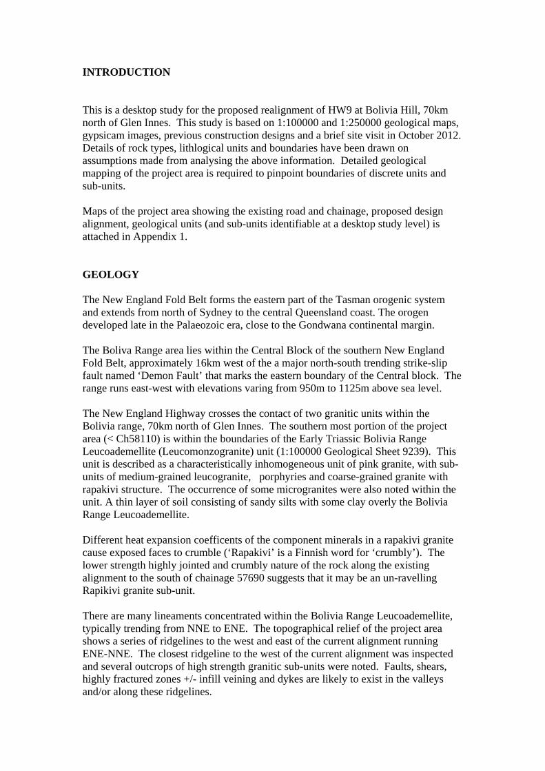
INTRODUCTION This is a desktop study for the proposed realignment of HW9 at Bolivia Hill, 70km north of Glen Innes. This study is based on 1:100000 and 1:250000 geological maps, gypsicam images, previous construction designs and a brief site visit in October 2012. Details of rock types, lithlogical units and boundaries have been drawn on assumptions made from analysing the above information. Detailed geological mapping of the project area is required to pinpoint boundaries of discrete units and sub-units. Maps of the project area showing the existing road and chainage, proposed design alignment, geological units (and sub-units identifiable at a desktop study level) is attached in Appendix 1. GEOLOGY The New England Fold Belt forms the eastern part of the Tasman orogenic system and extends from north of Sydney to the central Queensland coast. The orogen developed late in the Palaeozoic era, close to the Gondwana continental margin. The Boliva Range area lies within the Central Block of the southern New England Fold Belt, approximately 16km west of the a major north-south trending strike-slip fault named ‘Demon Fault’ that marks the eastern boundary of the Central block. The range runs east-west with elevations varing from 950m to 1125m above sea level. The New England Highway crosses the contact of two granitic units within the Bolivia range, 70km north of Glen Innes. The southern most portion of the project area (< Ch58110) is within the boundaries of the Early Triassic Bolivia Range Leucoademellite (Leucomonzogranite) unit (1:100000 Geological Sheet 9239). This unit is described as a characteristically inhomogeneous unit of pink granite, with sub-units of medium-grained leucogranite, porphyries and coarse-grained granite with rapakivi structure. The occurrence of some microgranites were also noted within the unit. A thin layer of soil consisting of sandy silts with some clay overly the Bolivia Range Leucoademellite. Different heat expansion coefficents of the component minerals in a rapakivi granite cause exposed faces to crumble (‘Rapakivi’ is a Finnish word for ‘crumbly’). The lower strength highly jointed and crumbly nature of the rock along the existing alignment to the south of chainage 57690 suggests that it may be an un-ravelling Rapikivi granite sub-unit. There are many lineaments concentrated within the Bolivia Range Leucoademellite, typically trending from NNE to ENE. The topographical relief of the project area shows a series of ridgelines to the west and east of the current alignment running ENE-NNE. The closest ridgeline to the west of the current alignment was inspected and several outcrops of high strength granitic sub-units were noted. Faults, shears, highly fractured zones +/- infill veining and dykes are likely to exist in the valleys and/or along these ridgelines.

Arsenic, Molybdenite and Tin, Tungsten, Bismuth and some Zinc were once mined in relatively small quantities from quartz veins in close proximity to the current road alignment. A brief visit to the site revealed many small unmapped workings on the ridge to the east of the current alignment, and a vertical shaft accessing a 40cm quartz vein hosting minor quantities of spahlerite (zinc sulphide) and traces of chalcopyrite (copper sulphide) in the adjacent valley to the west of the current alignment. North of Chainage 57690, sub-unit lithologies of the Bolivia Range Leucoademellite change abruptly. The rock in this portion of the project area is highly siliceous and resistant to weathering - characteristic of a porphyritic granitoid. Onion skin type jointing is commonly displayed in this sub-unit. Onion skin jointing in granitoids can be caused by either; uneven heating and cooling between the surface and interior of the rock which eventually leads to fracturing; or by the dissolution of feldspars by acidic water creating clay minerals and causing the outer layer of the rock to crumble and peel off like an onion. The project area to the north of Chainage 28110 is in the Late Permian Dundee Rhyodacite-Bolivia mass unit (1:100000 Geological Sheet 9239). The Bolivia mass is composed of a strongly porphyritic blue grey ignimbritic rhyodacite, identifieable by the presence of its quartz phenocrysts, zoned plagioclase crystals, biotite, hornblende and clinopyroxene, all set in a microgranular quartz-feldspar groundmass material. The felsic volcanic rock unit breaks down into dark brown sandy silts with clay, silty sands and sandy silts. Brickyard creek crosses the highway approx 600m north of Pyes Creek Road, and runs in an NNW direction. Boreholes drilled for a bridge reconstruction project in 1982 show diorite bedrock at 6m below sandy and clayey silts. Assuming that the bedrock was correctly identified, this would suggest that Brickyard creek may be following an intrusive diorite dyke within the Dundee Rhyodacite-Bolivia mass at this point. Similarly, Splitters Swamp Creek 2.4km up the highway is running in a NW direction - although bridge plans from 1885 show conglomerate bedrock 8m below deck level, in the context of the host environment it is likely that re-testing may reveal the creek bed to be a weathered igneous intrusion with hard core stones. QUARRIED MATERIALS With granitic materials throughout the project area, the potential for any excavated material to be reused in the job as selected material, drainage layer material, bridging layer material and bulk rock fill is high. Sampling and testing of the different sub-units identified along the project area will need to be undertaken in NATA certified laboratories to ensure materials have the characteristics required to meet the criteria set out in the RTA QA Specification R44 for each intended use. Appendix A4.2 of R44 outlines the minimum quality requirements of materials intended for re-use in construction, and is attached in Appendix 2 of this report for reference.

Site won materials found to contain acid sulphate, which is likely in areas that have been mined in the past, should be ruled out for certain uses. Sulphide bearing rock with a sulphide mineral content greater than 1% would have the potential to create a swelling road base product causing potential cracking in wearing course layers and also the potential to produce acidic runoff from earthworks structures such as road base, drainage rock and armour stone. The RTA guide to the management of acid sulphate materials should be consulted for further advice in dealing with acid sulphate rock. Aside from material won from excavations along the alignment, there are existing quarries in the vicinity of the project area, potentially capable of providing earthworks and pavement material to the project. Darryl McCarthy Constructions P/L owns and controls a Basalt quarry 32km west of Tenterfield, where material is blasted then hauled to a crushing plant 9km north of Tenterfield. The quarry produces sealing aggregates and gabion rock with a history of good performance on HW9 and HW16. The suppliers can produce a DGB20 base quality product by incorporating weathered granite gravel into the blend. Wayne McCarthy Concrete and Aggregate P/L operate a council owned Basalt quarry 2km east of Glen Innes, where materials are blasted and crushed onsite. The quarry produces sealing aggregates and gabion rock with a history of good performance on HW9 and HW12 and MR76. The suppliers can produce a DGB20 base quality product by incorporating weathered granite gravel into the blend. Recent products include a blend of crusher dust and granite gravel that appears very prone to shrinkage when stabilised. Hickeys Pit is a natural Granite gravel quarry 24km south of Tenterfield. The pit is privately owned by Mr. R. Hickey and controlled by Towne’s Contracting Pty Ltd. The pit can potentially supply select quality material, RSW backfill and general fill. Towne’s Contracting Pty Ltd also runs a NATA certified laboratory in Tenterfield. Hickeys Pit natural gravel has previously been used in bridge approaches on HW9 at Groomsbridge Tenterfield, deep lift stabilisation at Four Mile Ck and deep lift stabilisation of McClifty’s south of Bolivia Hill. It is noted that base quality materials sourced from the above quarries can be sensitive to moisture. DGB20 mixes need to be thoroughly tested to ensure compliance. A more detailed report should include a study of all surrounding pits and quarries. SLOPE STABILITY An historical railway line runs parallel on the upslope side of the highway for half of the project length. Deep rock-fill walls were constructed to support the railway line and small to medium sized slips are evident along the batters as slip scars and areas of cleared or changed vegetation. Localised areas of apparent slow creep are highlighted by the twisting of tree trunks on the rock fill batters.

A slope risk analysis conducted in 2006 identified the risk of rock falling from the railway rock fill embankment onto the existing highway around chainage 58020 as having a consequence class risk level of ARL2. Scaling and other minor remediation works have been carried out along the project area over the past few years, but have mainly only addressed loose boulders and tree root jacking in the highly jointed section south of chainage 57690. Investigations into the long term stability of the area are recommended before committing to an alignment that passes below this area. No assessments have yet been made on the 30m rock fill on the down slope side of the existing alignment, though irregularities in vegetation and scouring have been observed. GEOTECHNICAL DESIGN CUTTINGS Due to the highly jointed and weathered nature of the granite south of Chainage 57690, any excavation in this portion of the project is expected to be achievable with heavy excavators, with some provision for the use of rock-breakers and the possibility of blasting if hard un-weathered core stones are too large to break up mechanically. Due to erodible and jointed qualities which make the granite south of chainage 57690 relatively easily excavatable, consideration needs to be made to the long-term stability of any new cutting. Shallow batter angles of no less than 2(h):1(v) with maximum batter heights of 10m(v) and benches of 4m(h) are a reasonable starting point at a desktop study level. Detailed mapping and/ or intrusive geotechnical investigations are required to prescribe slope angle and batter height with some certainty. The hard siliceous granites north of Chainage 57690 are expected to be beyond the rippability threshold of heavy earthworks machinery. It is likely that the use of explosives will be necessary to cut into these rock units. Excavation of the adjacent railway line in 1880’s utilised explosives, and road cuttings in 1950’s were cut with 2m spaced blast holes. Access tracks for production drill rigs and trial blasting is will need to be considered for future excavations in this section. The hardness and resistance to weathering displayed in the rock units north of chainage 57690 would lend it to stand up very well at high angles and, with some consideration to jointing and fall zones, it is possible that batters could be sound if cut sub-vertically with maximum batter heights of 7m(v) with 4m(h) benches. ROCK-FILL EMBANKMENTS With the potential for a significant volume of rock meeting quality specifications for ‘rock-fill’ as specified in Appendix A4.2 of RTA QA Specification R44 (Appendix 2), the construction of rock-fill embankments are likely to be a preferred construction

option where embankment footprints need to be minimised. If batter angles need to be steeper than 40 degrees to minimise fill embankment footprints, other engineering options such as Reinforced Soil Walls will need to be considered. Specific requirements on rock-fill embankment materials and construction methods are outlined in: RTA QA Specification R44. Attached in Appendix 3 are example drawings of a 40 degree rock fill embankment and a 40 degree rock fill embankment transitioning into a cutting that comply with R44 construction design specifications. EARTH FILL EMBANKMENTS Where the size of fill batter footprints are less constrained, site won and imported earth fill can be used to construct earth fill embankments. Specific requirements on Earth Fill embankment materials and construction methods are outlined in: RTA QA Specification R44. Constructing 300mm lifts with a maximum rock size of less than 200mm and a maximum of 20% retained on a 37.5mm sieve is recommended to facilitate the use of a nuclear meter for compaction testing during construction. Attached in Appendix 4 are example drawings that comply with R44 construction design specifications. Illustrated are a 2:1 earth fill embankment and a 2:1 earth fill embankment transitioning into a cutting. REINFORCED SOIL WALLS (RSW) Where conditions restrict the construction of earth or rock fill embankments, engineered structures such as reinforced soils walls can be constructed sub-vertically. Earthworks in the southern end of the project and nearby natural gravel quarries may produce material that meets RTA QA Specification R57 requirements for material used as RSW backfill. Detailed geotechnical investigation and site specific designs will be required in the case that RSW walls are included for use in the project. PAVEMENT DESIGN The original pavement was constructed in 1940 with 150mm base unbound gravel over 150mm sub base unbound gravel. Since then there have been numerous chip re-seals (the last was 14mm in 2000), heavy patching and a 50mm AC overlay in 2009. A new pavement traffic loading analysis, modelled for a 20 year period, used classification count data recorded at count-station 91.169, Bolivia Hill. The records indicate that 20% of traffic is recorded as heavy vehicles. DESA was calculated at 1.29E+07 for the year 2031 using an annual growth rate of 1% (Appendix 5).

Taking into account the traffic loading, the local geology, the construction requirements in this project and assuming appropriate drainage is in place, a granular pavement with a design life of at least 20 years can be achieved with 300mm DGB20 (or 150mm DGB20 and 150mm GDS20) over 150mm of selected material. (Appendix 6). Rock-fill embankment diagrams shown in Appendix 3 and 4 are finished with the above pavement structure. The construction of trench drains or similar is recommended to prevent moisture ingress into the pavement through cut batters. In the case of encountering hard rock cutting floors or natural springs, a prevision for the addition of a 300mm drainage blanket as detailed in RTA QA Specification R44 may be required. Report prepared by: Report Reviewed and Authorised by:
Brendan Mitchell Geoff Kearns Scientific Officer Supervising Geotechnical Scientist March 2012 March 2012

Appendix 1
Geology Maps

Appendix 2
R44 A4.2

Appendix 3
Rock fill embankment

Appendix 4
Earth Fill Embankment

Appendix 5
Traffic Loading

Appendix 6
Pavement Design

860
880
840
900
820
920
940
960
980
860
920
5926059200
5914059100
5906059020
5898058940
5890058860
5882058780
5874058700
5866058620
5856058500
5844058380
5832058260
5820058140
5806057980
5792057860
5782057780
576605758057500
5742057360
5730057240
5718057120
57060
LegendExisting Alignment
Design Alignment
Contours
BoliviaRangeLeucograniteSuite
BoliviaMass
Weathered Jointed Granitoid
Siliceous Granitoid
High Strength Granite Outcrops
HW9 Bolivia Hill Realignment

#
SANDY CREEK
BRICKYARD CREEK
SPLITTERS SWAMP CK

(RTA COPYRIGHT AND USE OF THIS DOCUMENT - Refer to the Foreword after the Table of Contents)
Earthworks R44
Ed 3 / Rev 15 61
A4.2 Properties
Clause Location Value Test Pre-Treatment Test Condition
2.8.2 Material for Upper Zone of Formation other than Selected Material:
a) CBR10 day 8 min T117 T102/T103 100% Compaction b) Plasticity Index 25 max T109 T102/T103 2.8.3.1 Site won Selected Material: a) Selected Material Zone top 150 mm layer
CBR4 day – characteristic value (Q) Refer NOTES 3 and 4
30 min T117 T102/T103 100% Compaction
b) rest of Selected Material Zone CBR4 day – characteristic value (Q ) Refer NOTE 4
15 min T117 T102/T103 100% Compaction
c) Plasticity Index 15 max T109 T102/T103 NA 2.8.4 Verge material - CBR4 day 15 min T117 T102/T103 100% Compaction - Plasticity Index 6 and 12 T109 T102/T103 3.2 Shallow Embankments - CBR10 day 8 min T117 T102/T103 100% Compaction - Plasticity Index 25 max T109 T102/T103 3.4 Cutting Floors a) CBR10 day 8 min T117 T102/T103 100% Compaction b) Plasticity Index 25 max T109 T102/T103
Drainage Blanket: a) Point Load Strength Index Is(50) 1 MPa min T223 NA NA 3.2.5 &
3.4.2b) Wet/Dry Strength Variation 35% max T215 T102 NA
3.4.3 Type C3 Foundations in cuttings – backfill - CBR10 day 8 min T117 T102/T103 100% Compaction - Plasticity Index 25 max T109 T102/T103 5.1.1.1 Earth fill at “spill-through” bridge abutment
zone
- CBR10 day - characteristic value (Q ) Refer NOTE 4
15 min T117 T102/T103 100% Compaction
- Plasticity Index 15 max T109 T102/T103 - Emerson Class 5 min AS
1289.3.8.15.1.2.2 Rock Fill: a) Point Load Strength Index Is(50) 1 MPa min T223 NA NA b) Wet/Dry Strength Variation 35% max T215 T102 NA 5.3 Rock Facing: a) Point Load Strength Index Is(50) 1 MPa min T223 NA NA b) Wet/Dry Strength Variation 35% max T215 T102 NA
LEGEND: NA = not applicable max = maximum min = minimum
Note 1: Pre-treatment is not required where samples are taken from the compacted formation. Compaction for CBR test must be (% of MDD for Standard Compaction) shown in right column.
Note 2: Where pre-treatment is shown as “T102/T103”, determine the appropriate pre-treatment regime for the material in accordance with Clause 2.8.1.

150Verge 150 Verge
1252:1 125 2:1
700
300
40 Deg~1.2:1
40 Deg~1.2:1
Diagramatic only: NOT TO SCALE
TYPICAL ROCK FILL SECTION
Rockfill
Non-Select UZF CBR >8
Capping Layer
Base Quality DGB20Sub Base Quality DGS20
Selected MaterialSelected Material

C TYPICAL ROCK FILL TRANSITIONING INTO CUT SECTION150150125 Verge 2:1125
Non-Select UZF 900 Non-Select UZF 900
Capping Layer 300
Cut Fill Transition10m
800
Existing 500 Rockfill40 deg~1.2:1
500
Diagramatic only: NOT TO SCALE
1000
1200
Base Quality DGB20Sub Base Quality DGS20
Selected MaterialSelected Material
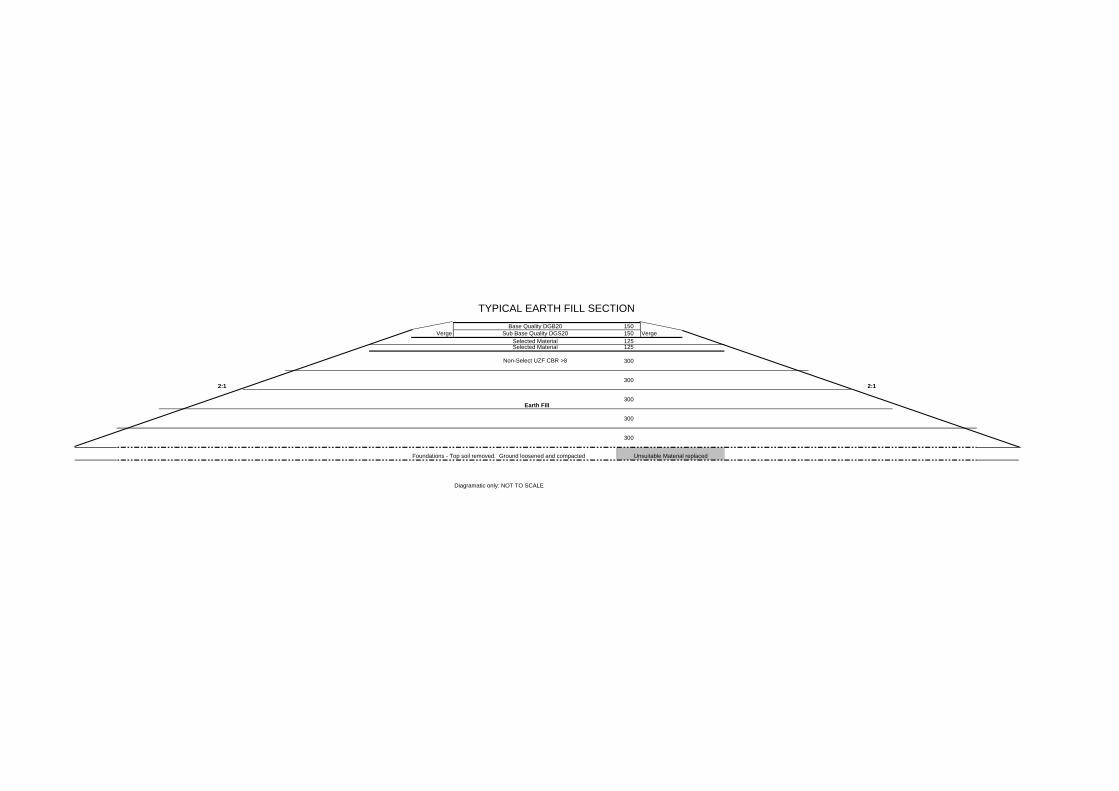
TYPICAL EARTH FILL SECTION150
Verge 150 Verge125125
300
2:1300
2:1
Earth Fill300
300
300
Foundations - Top soil removed. Ground loosened and compacted
Diagramatic only: NOT TO SCALE
Unsuitable Material replaced
Non-Select UZF CBR >8
Base Quality DGB20Sub Base Quality DGS20
Selected MaterialSelected Material

TYPICAL EARTH FILL TRANSITIONING INTO CUT SECTION150150125 Verge125
Non-Select UZF 900 Non-Select UZF 900
Cut Fill Transition10m
2:1
Existing Earth Fill
300mm Lifts
Diagramatic only: NOT TO SCALE
Base Quality DGB20Sub Base Quality DGS20
900
1800
Selected MaterialSelected Material

PAVEMENT TRAFFIC LOADINGS - ANALYSIS RESULTS
Input DetailsProject title :
Analysis by :Analysis date :
Design Year 1 : 2012Year 1 AADT : 4,173 Axle-Pairs
Axle-pairs/vehicle : 1.38DF - AADT direction factor : 1
NHVAG : 2.96 HVAG/HV%HV - Heavy Vehicles : 20.0%
LDF - Heavy Vehicles in design lane : 1.00
Flexible RigidDesign life : 20 years 40 years
Annual growth rate : 1.0% 1.0%
Analysis method : Presumptive data
ESA per HVAG : 0.90
SAR/ESA :
TLD Title:
TLD workbook filename:
TLD worksheet name: N/A
HVAG proportions: N/ASAST SADT TAST TADT TRDT QADTN/A N/A N/A N/A N/A N/A
Analysis DetailsPTL design filename :
PTL software version : 3M
Flexible Pavement Design LoadingsTotal at Year 20 (2031)
NDT :DESA :
CGF :
Fatigue of asphalt (SAR5) : Asphalt: 1.1Rutting & shape loss (SAR7) : Subgrade: 1.6
Fatigue of cemented materials (SAR12) : Cemented: 12.0
Rigid Pavement Design LoadingsNDT : 3.19E+07 HVAG at Year 40 (2051)
CGF :
General DetailsESA per Heavy Vehicle : 2.66
NHVAG : 2.96 HVAG/HVESA per HVAG : 0.90
SAST SADT TAST TADT TRDT QADTESA per axle group : N/A N/A N/A N/A N/A N/A
1.42E+07SAR/ESA
121.1 1.6
1.29E+07
Asphalt Cemented
9 December 2011
Subgrade
HW9 Bolivia Hill
G:\Eng Tech\BUS_UNITS\Geotechnical\0HW09New_England\Bolivia Hill\Calcs\Pavement Traffic Loadings.ptl
48.9
N/A
N/A
Brendan Mitchell
2.07E+071.55E+08
22.0
1.44E+07

FLEXIBLE PAVEMENT DESIGN - SUMMARY REPORTProject DetailsProject title:Location:Designer:Date of design:Comments:Design reliability: 95%
Traffic DetailsAsphalt Subgrade Cemented
Design traffic (SAR): 1.42E+07 2.07E+07 1.55E+08
Design period: 20 yearsAnnual growth rate: 1.0%
Layer DetailsLayer Thickness Ev Sub- Lower % Vol
No (mm) Material (MPa) layer? I/F Bitumen1 150 Granular 300 yes Rough N/A2 150 Granular 250 yes Rough N/A3 125 Granular 200 yes Rough N/A4 125 Sel. S/G 150 yes Rough N/A5 S/Inf Subgrade 50 N/A N/A N/A
Load DetailsHalf/Full axle model: FullTyre contact stress: 750 kPa
Design Details
Design filename:FPD software version: 5SCIRCLY software version: 5.0r (1 July 2010)
ResultsLayer Thickness Ev Poisson's Lower
No (mm) Description (MPa) Ev/Eh Ratio I/F 1-3.1 85 300 2.0 0.35 Rough 1-3.2 85 235 2.0 0.35 Rough 1-3.3 85 185 2.0 0.35 Rough 1-3.4 85 145 2.0 0.35 Rough 1-3.5 85 114 2.0 0.35 Rough 4.1 25 89 2.0 0.35 Rough 4.2 25 79 2.0 0.35 Rough 4.3 25 71 2.0 0.35 Rough 4.4 25 63 2.0 0.35 Rough 4.5 25 56 2.0 0.35 Rough 5 S/Inf 50 2.0 0.45 N/A
Layer Failure Failure Life Year ofNo Description Criterion Hor. Vert. Reps. Consumed Failure1 N/A N/A N/A N/A N/A N/A2 N/A N/A N/A N/A3 N/A N/A N/A N/A N/A N/A4 Rutting N/A 743 4.81E+07 43% 425 Rutting N/A 806.8 2.70E+07 77% 26Granular Subgrade
Granular BaseGranular Sub-baseSelected MaterialSelected Material
S/L Sel. S/G
S/L Sel. S/GGranular Subgrade
Max. Microstrain
S/L Sel. S/GS/L Sel. S/GS/L Sel. S/G
S/L GranularS/L Granular
S/L Granular
Description
Bolivia Hill RealignmentHW9 70km North of Glen InnisBrendan Mitchell12 December 2011
S/L Granular
Granular BaseGranular Sub-baseSelected MaterialSelected Material
Granular Subgrade
S/L Granular
G:\Eng Tech\BUS_UNITS\Geotechnical\0HW09New_England\Bolivia Hill\Calcs\Design1.fpd
Page 1 of 1