recent advances on electrically conductive adhesivesjagar/assets/agar_ectc_2010_2.pdf · 2010 12th...
TRANSCRIPT
2010 12th Electronics Packaging Technology Conference
Recent Advances on Electrically Conductive Adhesives
Rongwei Zhang1,2, Josh C. Agar2, C. P. Wong1,2,3 1School of Chemistry and Biochemistry and 2School of Materials Science and Engineering, Georgia Institute of Technology,
771 Ferst Drive, Atlanta, Georgia 30332 3Faculty of Engineering, The Chinese University of Hong Kong, Hong Kong Phone: 404-894-8391, fax: 404-894-9140, email: [email protected]
Abstract
As one of the promising lead-free interconnection materials, electrically conductive adhesive (ECA) has made considerable advances in recent years. Compared to metal solder, ECAs offer numerous advantages, such as environmental friendliness (elimination of lead usage and flux cleaning), mild processing conditions, fewer processing steps (reducing processing cost), low stress on the substrates and fine pitch capability. However, ECAs have some challenging issues, such as lower electrical and thermal conductivities compared to solder joints, conductivity fatigue in reliability tests, limited current carrying capability, poor impact performance, etc. To meet specific applications required for emerging electronic packaging technologies, worldwide research efforts have been devoted to improving the performance of ECAs, such as electrical and mechanical properties and the reliability under various conditions. Here, we summarize recent advances in isotropically conductive adhesive (ICA) technology. We mainly discuss how the electrical and reliability properties of ICAs can be engineered for electronic packaging applications.
Introduction to Electrically Conductive Adhesives (ECAs) With the new emphasis on green, sustainable technologies,
research into science and engineering of interconnect materials has changed dramatically. Research efforts have focused on two lead-free alternatives, lead-free metal solder alloys and polymer-based Electrically Conductive Adhesives (ECAs). [1-7] A number of lead-free solder alloys have found their way in commercial products. However, these lead-free solders possess technical limits, such as processibility, wetting capability, mechanical properties, fatigue and thermal behavior. Most significantly, current commercially available lead-free solders chosen by the majority of the US electronic industry, such as tin/silver (Sn/Ag) and tin/silver/copper (Sn/Ag/Cu), have higher melting temperatures (~220 oC) than eutectic tin-lead solder (183 oC). The higher melting temperatures result in solder reflow temperatures from 230 oC to over 260 oC. These higher processing temperatures severely limit the applicability of lead-free solders to organic/polymer packaged components and low-cost organic printed circuit boards/substrates. Moreover, the exposure of electronics to higher temperatures degrades component reliability. In addition, high reflow temperatures increase energy consumption and consequently the environmental and financial costs. Some low melting point lead-free alloys have been developed such as Sn/In (Tm, 120 oC) and Sn/Bi (Tm, 138 oC) (7). However, their material properties and processibility are still of concern. [8-9]
Compared to metal solder technology, ECAs offer numerous advantages, such as environmental friendliness
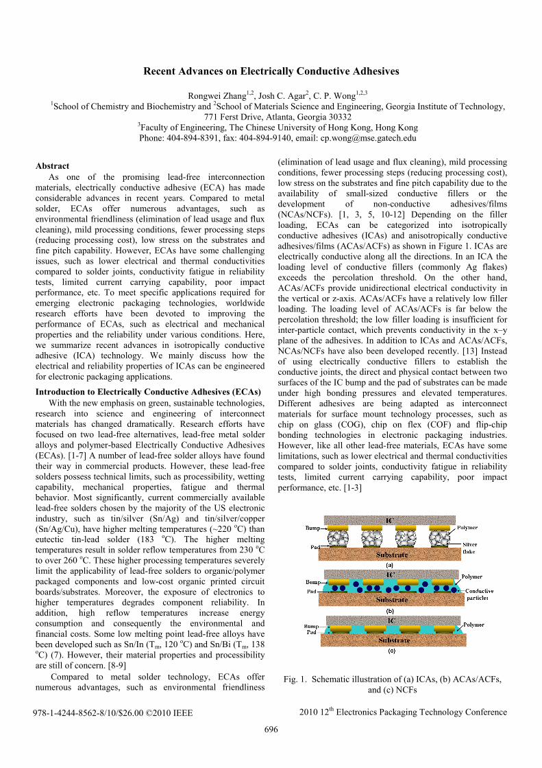
(elimination of lead usage and flux cleaning), mild processing conditions, fewer processing steps (reducing processing cost), low stress on the substrates and fine pitch capability due to the availability of small-sized conductive fillers or the development of non-conductive adhesives/films (NCAs/NCFs). [1, 3, 5, 10-12] Depending on the filler loading, ECAs can be categorized into isotropically conductive adhesives (ICAs) and anisotropically conductive adhesives/films (ACAs/ACFs) as shown in Figure 1. ICAs are electrically conductive along all the directions. In an ICA the loading level of conductive fillers (commonly Ag flakes) exceeds the percolation threshold. On the other hand, ACAs/ACFs provide unidirectional electrical conductivity in the vertical or z-axis. ACAs/ACFs have a relatively low filler loading. The loading level of ACAs/ACFs is far below the percolation threshold; the low filler loading is insufficient for inter-particle contact, which prevents conductivity in the x–y plane of the adhesives. In addition to ICAs and ACAs/ACFs, NCAs/NCFs have also been developed recently. [13] Instead of using electrically conductive fillers to establish the conductive joints, the direct and physical contact between two surfaces of the IC bump and the pad of substrates can be made under high bonding pressures and elevated temperatures. Different adhesives are being adapted as interconnect materials for surface mount technology processes, such as chip on glass (COG), chip on flex (COF) and flip-chip bonding technologies in electronic packaging industries. However, like all other lead-free materials, ECAs have some limitations, such as lower electrical and thermal conductivities compared to solder joints, conductivity fatigue in reliability tests, limited current carrying capability, poor impact performance, etc. [1-3]
Fig. 1. Schematic illustration of (a) ICAs, (b) ACAs/ACFs, and (c) NCFs
696
978-1-4244-8562-8/10/$26.00 ©2010 IEEE
2010 12th Electronics Packaging Technology Conference
The discussion in the following sections mainly focuses on isotropically conductive adhesives (ICAs). ICA mainly consists of a polymeric resin (epoxy, silicone, polyurethane or polyimide) that provides physical and mechanical properties such as adhesion, mechanical strength, impact strength, and metal fillers (silver, gold, nickel or copper) that conduct electricity. [1, 14-18] Table 1 shows a general comparison between tin-lead solder and generic commercialized ICAs. [19] Note that the performance of ICAs is strongly dependent on the filler loading level, polymer matrix, the interaction between fillers and polymer matrix, processing conditions, etc.
Table 1. Conductive adhesives compared with solder. [19]
Characteristic Sn/Pb solder ICA Volume resistivity
(Ω cm) 0.000015 0.00035
Typical junction R (mΩ)
10-15 <25
Thermal conductivity
(W/m K)
30 3.5
Shear strength (psi) >2200 2000 Finest pitch (mil) 12 <6-8
Minimum processing temperature
(oC)
215 150-170
Environmental impact
Negative Very minor
Thermal fatigue Yes Minimal
Conduction Mechanisms of ICAs The formation of electrical conductive paths in ICAs is
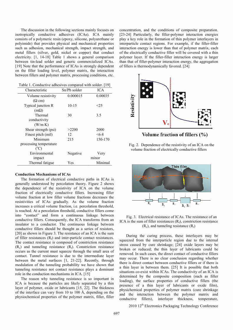
generally understood by percolation theory. Figure 2 shows the dependence of the resistivity of ICA on the volume fraction of electrically conductive fillers. Increasing filler volume fraction at low filler volume fractions decreases the resistivities of ICAs gradually. As the volume fraction increases a critical volume fraction, i.e. percolation threshold, is reached. At a percolation threshold, conductive fillers come into “contact” and form a continuous linkage between conductive fillers. Consequently, the ICA transforms from an insulator to a conductor. The continuous linkage between conductive fillers should be thought as a series of resistors, [20] as shown in Figure 3. The resistance of an ICA is the sum of filler resistances (Rf) and inter-particle contact resistances. The contact resistance is composed of constriction resistance (Rc) and tunneling resistance (Rt). Constriction resistance occurs as the current must squeeze through the small area of contact. Tunnel resistance is due to the intermediate layer between the metal surfaces [1, 21-22]. Recently, through modulation of the tunneling probability we have shown that tunneling resistance not contact resistance plays a dominant role in the conduction mechanisms in ICA. [15]
The reason why tunneling resistance is so important in ICA is because the particles are likely separated by a thin layer of polymer, oxide or lubricants [15, 22]. The thickness of the interface can vary from 10 to 100 Å, depending on the physiochemical properties of the polymer matrix, filler, filler
concentration, and the conditions of composite preparation. [23-24] Particularly, the filler-polymer interaction energies play a key role in the formation of thin polymer interlayers in interparticle contact regions. For example, if the filler-filler interaction energy is lower than that of polymer matrix, each of the electrically conductive filler will be covered with a thin polymer layer. If the filler-filler interaction energy is larger than that of filler-polymer interaction energy, the aggregation of fillers is thermodynamically favored. [24]
Fig. 2. Dependence of the resistivity of an ICA on the volume fraction of electrically conductive fillers
Fig. 3. Electrical resistance of ICAs. The resistance of an ICA is the sum of filler resistances (Rf), constriction resistance
(Rc), and tunneling resistance (Rt) During the curing process, these interlayers may be
squeezed from the interparticle region due to the internal stress caused by cure shrinkage; [24] oxide layers may be broken or reduced; the thin layer of lubricants could be removed. In such cases, the direct contact of conductive fillers may occur. There is no clear conclusion regarding whether there is direct contact between conductive fillers or if there is a thin layer in between them. [25] It is possible that both situations co-exist within ICAs. The conductivity of an ICA is determined by the composite composition (such as filler loading), the surface properties of conductive fillers (the presence of a thin layer of lubricants or oxide film), physichemical properties of polymer matrix (cure shrinkage and the interaction between the polymer matrix and conductive fillers), interlayer thickness, temperature,
697
2010 12th Electronics Packaging Technology Conference
processing conditions of ICAs, etc. [24] In order to achieve conductivity, the volume fraction of conductive fillers in an ICA must be equal to or higher than the critical volume fraction. Similar to solders, ICAs provide the dual functions of electrical connection and mechanical bonding in an interconnection joint. In ICA joints, the polymer resin provides mechanical stability and the conductive filler provides electrical conductivity. Filler loadings which are too high cause mechanical integrity of adhesive joints to deteriorate. Therefore, the challenge in formulating ICAs is to maximize conductive filler content to achieve high electrical conductivity without adversely affecting the mechanical properties. In typical ICA formulation, the volume fraction of conductive fillers is about 25–30%. [26-27]
Improvement of Electrical Conductivity Compared with metal solders, ICAs have lower electrical
conductivity. There is an increasing need for ICAs with higher electrical conductivity in the electronic industry. Various approaches to formulate highly conductive ICAs have been reported in recent years. These approaches include (1) increasing the polymer matrix shrinkage; (2) incorporation of short-chain diacids and reducing agents; (3) low temperature transient liquid phase sintering; (4) incorporation of one-dimensional conductive fillers; (5) low temperature sintering of Ag nanoparticles. [1] We mainly focus on the last two technologies.
High-aspect-ratio conductive fillers enable the establishment of conductive networks within a polymer matrix at much lower filler loading than that of spherical particles. A low filler loading enables the preparation of highly conductive ICAs without degradation of ICA mechanical properties and processibility. Wu et al. reported that the resistivity of ICAs filled with 56 wt% Ag nanowires (30 nm in diameter and a length up to 1.5 μm) was 1.2×10⁻⁴ Ω cm. The resistivity was significantly lower than that of ICAs filled with 1 μm and 100 nm Ag particles. [28] Several possible reasons for the improved electrical conductivity were proposed, including larger contact area, fewer contact points, more stable contact and enhanced tunneling between these particles due to the presence of a small amount of Ag nanoparticles. Moreover, ICAs filled with Ag nanowires have a better shear strength on an alumina plate (17.6 MPa) than that of ICAs filled with micron-sized Ag particles (17.3 MPa). [28] Similar results were reported by Tao et al. [29] Chen et al. demonstrated that the resistivity of ICAs could be improved by adding diluents containing Ag nanoparticles and Ag nanowires. [30] Besides Ag nanowires, carbon nanotubes (CNTs) have also been added to ICA formulations to improve electrical conductivity. Table 2 shows the effect of adding multi-walled CNTs (MWCNTs) on the electrical resistivity of Ag filled ICAs with different Ag contents. [31] The addition of MWCNTs into the formulation improves the electrical conductivity dramatically for ICAs whose filler loading is below percolation threshold. One dimensional fillers like CNTs, improve the contact between conductive fillers and facilitate the formation of 3-D conductive networks. This improved contact between conductive fillers is especially significant prior to reaching the percolation threshold. However, no significant improvement of electrical conductivity is observed when the Ag filler loadings reach the percolation threshold. Oh et al. investigated
the effect of adding single-walled CNTs (SWCNTs) with different surface properties on the electrical resistivity of a commercial Ag paste filled with 80 wt% Ag powders. [32] It was found that the addition of raw SWCNTs into the Ag paste did not improve the electrical conductivity. The addition of an optimized amount (1.5 wt%) of acid-treated SWCNTs can decrease the electrical resistivity significantly. This decrease in resistivity was the result of increased dispersion and p-doping effects. However, the resistivity increased with the addition of more acid-treated SWCNTs. With the addition of Ag-plated SWCNTs, the resistivity of the commercial Ag-filled ICA was decreased by 83%.
Recently, Ag nanoparticles are proposed to be used as conductive fillers for ICAs in an attempt to improve the electrical conductivity. The addition of Ag nanoparticles increased the number of contact points between conductive fillers. Although the incorporation of Ag nanoparticles decreases the resistivity near the percolation threshold, [33] the addition of Ag nanoparticles into micro-sized Ag flakes usually increase the resistivity dramatically if no sintering occurs. The increase in resistivity is the result of increased contact resistance. [33-36] Through SEM studies, Ye et al. observed that addition of Ag nanoparticles into a polymer matrix with micron-sized conductive fillers decreases the chance of direct contact among micron-sized fillers and the contact area between nano- and micron- sized particles is smaller than that between micron-sized particles. [34] In addition, the number of contact points significantly increase. As a result, contact resistance of ICAs filled with nano- and micron-sized particles increases as the percentage of Ag nanoparticles increases. However, some research has shown that the electrical conductivity of ICAs can be significantly improved by the addition of Ag nanoparticles. [16, 35, 37-38]
Table 2. Electrical properties of the CNTs/Ag/epoxy
composites with different compositions. [31] Ag(wt%) 45 52 57 66.5 72
Bulk resistivity of ICAs,
ρ1 (Ω⋅cm)
>>108 6.91×10⁶ 1.04×10⁶ 1.01×10⁴ 1.5×10⁻³
Bulk resistivity of ICAs with the
addition of CNTs, ρ2 (Ω⋅cm)
4.8×10³ 3.82×101 2.4×10⁻² 6.47×10⁻³ 1.43×10⁻³
CNTs (wt%)
1.35 1.0 0.4 0.27 0.24
ρ1/ρ2 ---- ≈105 ≈108 ≈106 1.05
In order to develop highly conductive ICAs filled with Ag
nanoparticles, it is essential to achieving the sintering between conductive fillers to reduce or eliminate contact resistance effectively within the polymer matrix at curing temperatures. Sintering is dependent on many factors such as organic molecules on the nanoparticle surfaces, particle size, pressure, atmospheric gas, temperature and sintering duration. [39] In particular, removal of organic molecules (or silver oxide) from the surface of Ag nanoparticles plays an important role in sintering onsets, extent of densification and final grain size.
698
2010 12th Electronics Packaging Technology Conference
[40] The challenges of low temperature sintering (<200 oC) of Ag nanoparticles within the polymer matrix lies in the facts that (i) most excellent polymeric dispersants [41-44] (such as polyvinylpyrrolidone) or other small molecules with a long alkyl chain [45-46] do not desorb or decompose at low temperatures. This is a problem because the removal of organic molecules is a prerequisite for sintering to occur; (ii) the sintering of Ag nanoparticles in polymer composites is hindered by high volume fraction (typically 70-80 vol%) of highly cross-linked polymer matrices. [35] The synthesis of Ag nanoparticles that sinter at low temperatures is critical for the preparation of highly conductive ICAs.
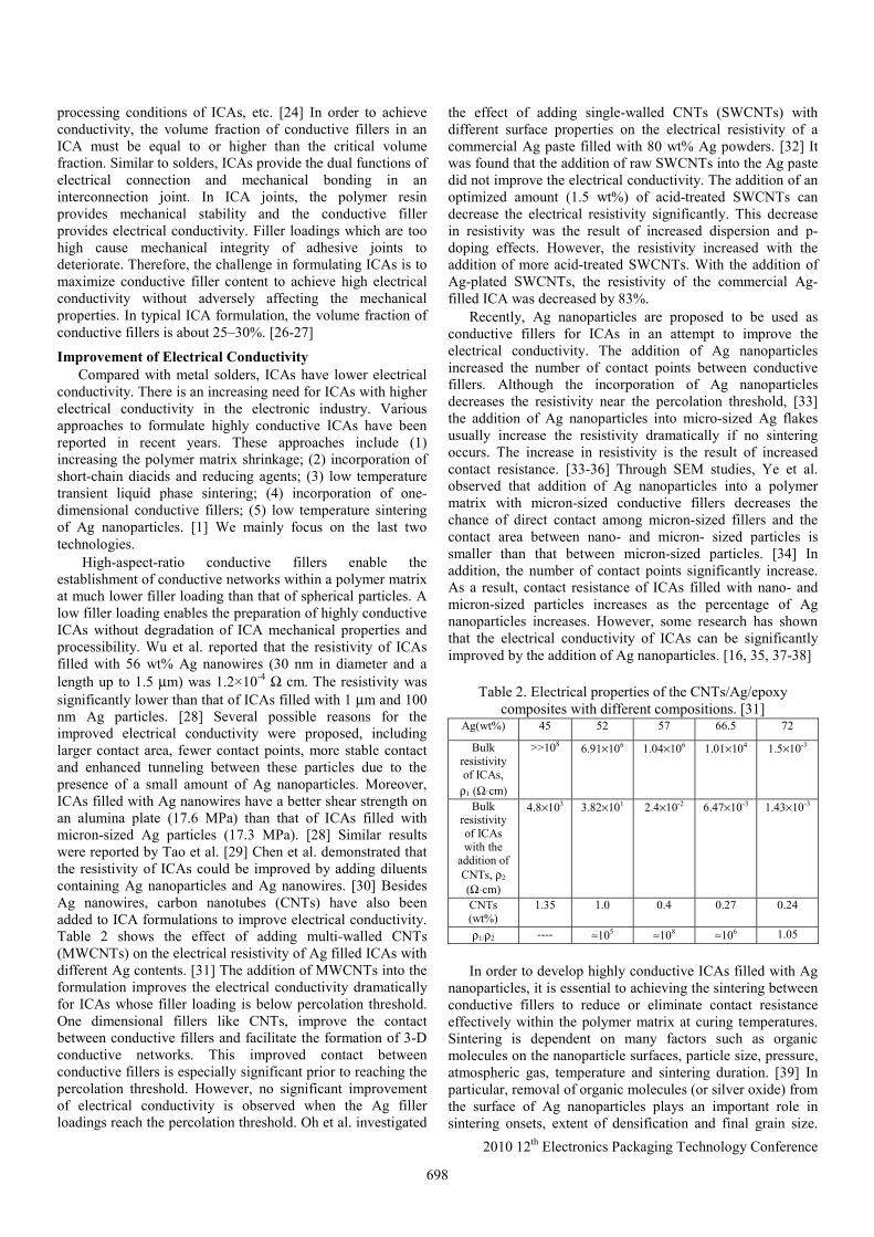
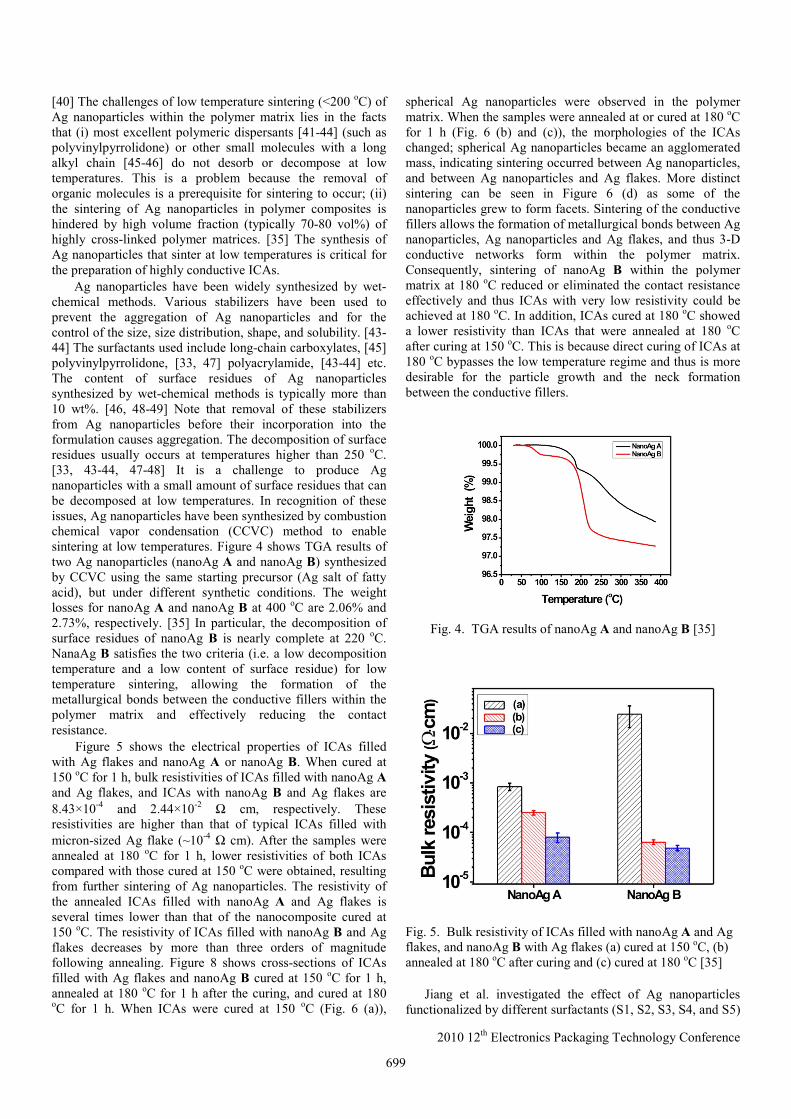
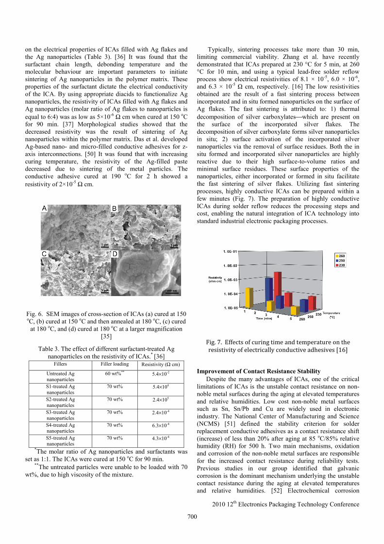
Ag nanoparticles have been widely synthesized by wet-chemical methods. Various stabilizers have been used to prevent the aggregation of Ag nanoparticles and for the control of the size, size distribution, shape, and solubility. [43-44] The surfactants used include long-chain carboxylates, [45] polyvinylpyrrolidone, [33, 47] polyacrylamide, [43-44] etc. The content of surface residues of Ag nanoparticles synthesized by wet-chemical methods is typically more than 10 wt%. [46, 48-49] Note that removal of these stabilizers from Ag nanoparticles before their incorporation into the formulation causes aggregation. The decomposition of surface residues usually occurs at temperatures higher than 250 oC. [33, 43-44, 47-48] It is a challenge to produce Ag nanoparticles with a small amount of surface residues that can be decomposed at low temperatures. In recognition of these issues, Ag nanoparticles have been synthesized by combustion chemical vapor condensation (CCVC) method to enable sintering at low temperatures. Figure 4 shows TGA results of two Ag nanoparticles (nanoAg A and nanoAg B) synthesized by CCVC using the same starting precursor (Ag salt of fatty acid), but under different synthetic conditions. The weight losses for nanoAg A and nanoAg B at 400 oC are 2.06% and 2.73%, respectively. [35] In particular, the decomposition of surface residues of nanoAg B is nearly complete at 220 oC. NanaAg B satisfies the two criteria (i.e. a low decomposition temperature and a low content of surface residue) for low temperature sintering, allowing the formation of the metallurgical bonds between the conductive fillers within the polymer matrix and effectively reducing the contact resistance. Figure 5 shows the electrical properties of ICAs filled with Ag flakes and nanoAg A or nanoAg B. When cured at 150 oC for 1 h, bulk resistivities of ICAs filled with nanoAg A and Ag flakes, and ICAs with nanoAg B and Ag flakes are 8.43×10⁻⁴ and 2.44×10⁻² Ω cm, respectively. These resistivities are higher than that of typical ICAs filled with micron-sized Ag flake (~10-4 Ω cm). After the samples were annealed at 180 oC for 1 h, lower resistivities of both ICAs compared with those cured at 150 oC were obtained, resulting from further sintering of Ag nanoparticles. The resistivity of the annealed ICAs filled with nanoAg A and Ag flakes is several times lower than that of the nanocomposite cured at 150 oC. The resistivity of ICAs filled with nanoAg B and Ag flakes decreases by more than three orders of magnitude following annealing. Figure 8 shows cross-sections of ICAs filled with Ag flakes and nanoAg B cured at 150 oC for 1 h, annealed at 180 oC for 1 h after the curing, and cured at 180 oC for 1 h. When ICAs were cured at 150 oC (Fig. 6 (a)),
spherical Ag nanoparticles were observed in the polymer matrix. When the samples were annealed at or cured at 180 oC for 1 h (Fig. 6 (b) and (c)), the morphologies of the ICAs changed; spherical Ag nanoparticles became an agglomerated mass, indicating sintering occurred between Ag nanoparticles, and between Ag nanoparticles and Ag flakes. More distinct sintering can be seen in Figure 6 (d) as some of the nanoparticles grew to form facets. Sintering of the conductive fillers allows the formation of metallurgical bonds between Ag nanoparticles, Ag nanoparticles and Ag flakes, and thus 3-D conductive networks form within the polymer matrix. Consequently, sintering of nanoAg B within the polymer matrix at 180 oC reduced or eliminated the contact resistance effectively and thus ICAs with very low resistivity could be achieved at 180 oC. In addition, ICAs cured at 180 oC showed a lower resistivity than ICAs that were annealed at 180 oC after curing at 150 oC. This is because direct curing of ICAs at 180 oC bypasses the low temperature regime and thus is more desirable for the particle growth and the neck formation between the conductive fillers.
Fig. 4. TGA results of nanoAg A and nanoAg B [35]
Fig. 5. Bulk resistivity of ICAs filled with nanoAg A and Ag flakes, and nanoAg B with Ag flakes (a) cured at 150 oC, (b) annealed at 180 oC after curing and (c) cured at 180 oC [35]
Jiang et al. investigated the effect of Ag nanoparticles functionalized by different surfactants (S1, S2, S3, S4, and S5)
699
2010 12th Electronics Packaging Technology Conference
on the electrical properties of ICAs filled with Ag flakes and the Ag nanoparticles (Table 3). [36] It was found that the surfactant chain length, debonding temperature and the molecular behaviour are important parameters to initiate sintering of Ag nanoparticles in the polymer matrix. These properties of the surfactant dictate the electrical conductivity of the ICA. By using appropriate diacids to functionalize Ag nanoparticles, the resistivity of ICAs filled with Ag flakes and Ag nanoparticles (molar ratio of Ag flakes to nanoparticles is equal to 6:4) was as low as 5×10⁻⁶ Ω cm when cured at 150 oC for 90 min. [37] Morphological studies showed that the decreased resistivity was the result of sintering of Ag nanoparticles within the polymer matrix. Das et al. developed Ag-based nano- and micro-filled conductive adhesives for z-axis interconnections. [50] It was found that with increasing curing temperature, the resistivity of the Ag-filled paste decreased due to sintering of the metal particles. The conductive adhesive cured at 190 oC for 2 h showed a resistivity of 2×10⁻⁵ Ω cm.
Fig. 6. SEM images of cross-section of ICAs (a) cured at 150 oC, (b) cured at 150 oC and then annealed at 180 oC, (c) cured
at 180 oC, and (d) cured at 180 oC at a larger magnification [35]
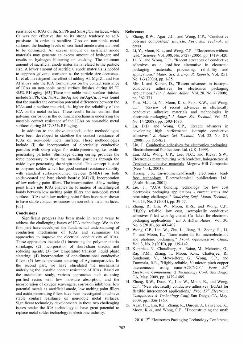
Table 3. The effect of different surfactant-treated Ag nanoparticles on the resistivity of ICAs.* [36]
Fillers Filler loading Resistivity (Ω cm)
Untreated Ag nanoparticles
60 wt%** 5.4×10⁻²
S1-treated Ag nanoparticles
70 wt% 5.4×10⁴
S2-treated Ag nanoparticles
70 wt% 2.4×10⁵
S3-treated Ag nanoparticles
70 wt% 2.4×10⁻⁴
S4-treated Ag nanoparticles
70 wt% 6.3×10⁻⁴
S5-treated Ag nanoparticles
70 wt% 4.3×10⁻⁴
*The molar ratio of Ag nanoparticles and surfactants was set as 1:1. The ICAs were cured at 150 oC for 90 min.
**The untreated particles were unable to be loaded with 70 wt%, due to high viscosity of the mixture.
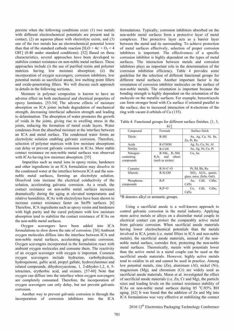
Typically, sintering processes take more than 30 min, limiting commercial viability. Zhang et al. have recently demonstrated that ICAs prepared at 230 °C for 5 min, at 260 °C for 10 min, and using a typical lead-free solder reflow process show electrical resistivities of 8.1 × 10⁻⁵, 6.0 × 10⁻⁶, and 6.3 × 10⁻⁵ Ω cm, respectively. [16] The low resistivities obtained are the result of a fast sintering process between incorporated and in situ formed nanoparticles on the surface of Ag flakes. The fast sintering is attributed to: 1) thermal decomposition of silver carboxylates⎯which are present on the surface of the incorporated silver flakes. The decomposition of silver carboxylate forms silver nanoparticles in situ; 2) surface activation of the incorporated silver nanoparticles via the removal of surface residues. Both the in situ formed and incorporated silver nanoparticles are highly reactive due to their high surface-to-volume ratios and minimal surface residues. These surface properties of the nanoparticles, either incorporated or formed in situ facilitate the fast sintering of silver flakes. Utilizing fast sintering processes, highly conductive ICAs can be prepared within a few minutes (Fig. 7). The preparation of highly conductive ICAs during solder reflow reduces the processing steps and cost, enabling the natural integration of ICA technology into standard industrial electronic packaging processes.
Fig. 7. Effects of curing time and temperature on the resistivity of electrically conductive adhesives [16] Improvement of Contact Resistance Stability
Despite the many advantages of ICAs, one of the critical limitations of ICAs is the unstable contact resistance on non-noble metal surfaces during the aging at elevated temperatures and relative humidities. Low cost non-noble metal surfaces such as Sn, Sn/Pb and Cu are widely used in electronic industry. The National Center of Manufacturing and Science (NCMS) [51] defined the stability criterion for solder replacement conductive adhesives as a contact resistance shift (increase) of less than 20% after aging at 85 oC/85% relative humidity (RH) for 500 h. Two main mechanisms, oxidation and corrosion of the non-noble metal surfaces are responsible for the increased contact resistance during reliability tests. Previous studies in our group identified that galvanic corrosion is the dominant mechanism underlying the unstable contact resistance during the aging at elevated temperatures and relative humidities. [52] Electrochemical corrosion
700
2010 12th Electronics Packaging Technology Conference
persists when the following conditions exist: (1) two metals with different electrochemical potentials are present and in contact, (2) an aqueous phase with electrolyte exists, and (3) one of the two metals has an electrochemical potential lower than that of the standard cathode reaction [H2O + 4e- + O2 = 4 OH-] (0.40 under standard conditions). [52] Based on these characteristics, several approaches have been developed to stabilize contact resistance on non-noble metal surfaces. These approaches include (i) the use of purified resins and polymer matrices having low moisture absorption; (ii) the incorporation of oxygen scavengers, corrosion inhibitors, low potential metals as sacrificial anode, low melting point fillers and oxide-penetrating fillers. We will discuss each approach in details in the following sections.
Moisture in polymer composites is known to have an adverse effect on both mechanical and electrical properties of epoxy laminates. [53-54] The adverse effects of moisture absorption on ICA joints include degradation of mechanical strength, decreasing interfacial adhesion strength and leading to delamination. The absorption of water promotes the growth of voids in the joints, giving rise to swelling stress in the joints, inducing the formation of metal oxide layers. Water condenses from the absorbed moisture at the interface between an ICA and metal surface. The condensed water forms an electrolytic solution enabling galvanic corrosion. Therefore, selection of polymer matrices with low moisture absorptions can delay or prevent galvanic corrosion in ICAs. More stable contact resistance on non-noble metal surfaces was observed with ICAs having low moisture absorption. [55] Impurities such as metal ions in epoxy resins, hardeners and other ingredients in an ICA formulation may dissolve in the condensed water at the interface between ICA and the non-noble metal surfaces, forming an electrolyte solution. Dissolved ions increase the electrical conductivity of the solution, accelerating galvanic corrosion. As a result, the contact resistance on non-noble metal surfaces increases dramatically during the aging at elevated temperatures and relative humidities. ICAs with electrolytes have been shown to increase contact resistance faster on Sn/Pb surfaces. [6] Therefore, ICA ingredients such as epoxy resins and hardeners with high purity and the cured polymers with low moisture absorption tend to stabilize the contact resistance of ICAs on the non-noble metal surfaces.
Oxygen scavengers have been added into ICA formulations to slow down the rate of corrosion. [56] Ambient oxygen molecules diffuse into the interface between ICA and non-noble metal surfaces, accelerating galvanic corrosion. Oxygen scavengers incorporated in the formulation react with ambient oxygen molecules and consume them. The reactivity of an oxygen scavenger with oxygen is important. Common oxygen scavengers include hydrazine, carbohydrazide, hydroquinone, gallic acid, propyl gallate, hydroxylamines and related compounds, dihydroxyacetone, 1, 2-dihydro-1,2, 4, 5-tetrazines, erythorbic acid, and oximes. [57-60] Note that oxygen can diffuse into the interface when oxygen scavengers are completely consumed. Therefore, the incorporation of oxygen scavengers can only delay, but not prevent galvanic corrosion.
Another way to prevent galvanic corrosion is through the incorporation of corrosion inhibitors into the ICA
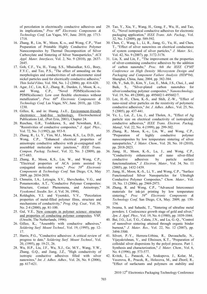
formulations. Typically, corrosion inhibitors absorbed on the non-noble metal surfaces form a protective layer of metal complexes. This protective layer acts as a barrier layer between the metal and its surrounding. To achieve protection of metal surfaces effectively, selection of proper corrosion inhibitors is important. The effectiveness of a specific corrosion inhibitor is highly dependent on the types of metal surfaces. The interaction between metals and corrosion inhibitors plays an important role in the determination of the corrosion inhibition efficiency. Table 4 provides some guideline for the selection of different functional groups for different metal surfaces. Another important factor is the orientation of corrosion inhibitor molecules on the surface of non-noble metals. The orientation is important because the bonding strength is highly dependent on the orientation of the molecule on the metallic surfaces. For example, benzotriazole can form stronger bond with Cu surface if oriented parallel to the surface, due to increased interaction of π-electrons of the ring with vacant d orbitals of Cu (135).
Table 4. Functional groups for different surface finishes. [1, 3,
61] Compound Formula Surface finish
Thiols R-SH Au, Ag, Cu, Ni, Sn, Zn, Pt, Ru
Acids R-COOH Ag, Fe, Co, Ni, Al Nitriles R-C≡N Au, Ag, Ni, Cu, Pt Nitrogen-
containing compounds
R-NH2, R2-NH, R3N, and others (such as azoles)
Cu, Au
Cyanates R-N=C=O Pt, Pd, Rh, Ru Silanols R-Si-OH SiO2, Al2O3, quartz,
glass, mica, ZnSe, GeO2 Phosphorus
compounds R3P Au, CdS, CdSe,
CdTe R3P=O Co, CdS, CdSe,
CdTe *R denotes alkyl or aromatic groups.
Using a sacrificial anode is a well-known approach to
control galvanic corrosion in the metal industry. Applying more active metals or alloys on a dissimilar metal couple in electrical contact can protect the comparably active metal from galvanic corrosion. When sacrificial anode materials having lower electrochemical potentials than the metals involved in ICA joints (i.e. metal fillers in ICA and non-noble metals), the sacrificial anode materials, instead of the non-noble metal surface, corrodes first, protecting the non-noble metal surfaces. Theoretically, metals with potentials lower than the active metal in a metal couple can be used as the sacrificial anode materials. However, highly active metals tend to oxidize in air and cannot be used in practice. Among low potential metals, zinc (Zn), aluminum (Al), nickel (Ni), magnesium (Mg), and chromium (Cr) are widely used as sacrificial anode materials. Moon et al. investigated the effect of sacrificial anode materials (i.e. Zn, Cr and Mg), the particle sizes and loading levels on the contact resistance stability of ICAs on non-noble metal surfaces during 85 oC/85% RH aging. [62] It was found that the addition of Zn and Mg into ICA formulations was very effective at stabilizing the contact
701
2010 12th Electronics Packaging Technology Conference
resistance of ICAs on Sn, Sn/Pb and Sn/Ag/Cu surfaces, while Cr was not effective due to its strong tendency to self-passivate. In order to stabilize ICAs on non-noble metal surfaces, the loading levels of sacrificial anode materials need to be optimized. An excess amount of sacrificial anode materials may generate an excess amount of hydrogen and results in hydrogen blistering or cracking. The optimum amount of sacrificial anode materials is related to the particle size. A lower amount of sacrificial anode materials is needed to suppress galvanic corrosion as the particle size decreases. Li et al. investigated the effect of adding Al, Mg, Zn and two Al alloys into the ICA formulations on the contact resistance of ICAs on non-noble metal surface finishes during 85 oC /85% RH aging. [63] These non-noble metal surface finishes include Sn/Pb, Cu, Ni/Au, Sn/Ag and Sn/Ag/Cu. It was found that the smaller the corrosion potential differences between the ICAs and a surface material, the higher the reliability of the ICA on the metal surface. These results further confirm that galvanic corrosion is the dominant mechanism underlying the unstable contact resistance of the ICAs on non-noble metal surfaces during 85 oC/85% RH aging.
In addition to the above methods, other methodologies have been developed to stabilize the contact resistance of ICAs on non-noble metal surfaces. These methodologies include (i) the incorporation of electrically conductive particles with sharp edges for oxide-penetrating, i.e. oxide-penetrating particles. Shrinkage during curing provides the force necessary to drive the metallic particles through the oxide layer penetrating the virgin metal. This concept is used in polymer–solder which has good contact resistance stability with standard surface-mounted devices (SMDs) on both solder-coated and bare circuit boards; [64] (ii) Incorporation of low melting point fillers. The incorporation of low melting point fillers into ICAs enables the formation of metallurgical bonds between low melting point fillers and non-noble metal surfaces. ICAs with low melting point fillers have been shown to have stable contact resistances on non-noble metal surfaces. [65]
Conclusions Significant progress has been made in recent years to
address the challenging issues of ICA technology. We in the first part have developed the fundamental understanding of conduction mechanism of ICAs and summarize the approaches to improve the electrical conductivity of ICAs. These approaches include (1) increasing the polymer matrix shrinkage; (2) incorporation of short-chain diacids and reducing agents; (3) low temperature transient liquid phase sintering; (4) incorporation of one-dimensional conductive fillers; (5) low temperature sintering of Ag nanoparticles. In the second part, we have elucidated the mechanisms underlying the unstable contact resistance of ICAs. Based on the mechanism study, various approaches such as using purified resins with low moisture absorption, and the incorporation of oxygen scavengers, corrosion inhibitors, low potential metals as sacrificial anode, low melting point fillers and oxide-penetrating fillers have been investigated to achieve stable contact resistance on non-noble metal surfaces. Significant technology developments in these two challenging issues render the ICA technology to have great potential to replace metal solder technology in electronic industry.
References 1. Zhang, R.W., Agar, J.C., and Wong, C.P., "Conductive
polymer composites," Encyclo. Poly. Sci. Technol., in press.
2. Li, Y., Moon, K.-s., and Wong, C.P., "Electronics without lead," Science, Vol. 308, No. 5727 (2005), pp. 1419-1420.
3. Li, Y. and Wong, C.P., "Recent advances of conductive adhesives as a lead-free alternative in electronic packaging: materials, processing, reliability and applications," Mater. Sci. & Eng., R: Reports, Vol. R51, No. 1-3 (2006), pp. 1-35.
4. Mir, I. and Kumar, D., "Recent advances in isotropic conductive adhesives for electronics packaging applications," Int. J. Adhes. Adhes., Vol. 28, No. 7 (2008), pp. 362-371.
5. Yim, M.J., Li, Y., Moon, K.-s., Paik, K.W., and Wong, C.P., "Review of recent advances in electrically conductive adhesive materials and technologies in electronic packaging," J. Adhes. Sci. Technol., Vol. 22, No. 14 (2008), pp. 1593-1630.
6. Lu, D.D. and Wong, C.P., "Recent advances in developing high performance isotropic conductive adhesives," J. Adhes. Sci. Technol., Vol. 22, No. 8-9 (2008), pp. 835-851.
7. Liu, J., Conductive adhesives for electronics packaging, Electrochemical Publications Ltd. (UK, 1999).
8. Lau, J.H., Wong, C.P., Lee, N.C., and Ricky, S.W., Electronics manufacturing with lead-free, halogen-free & Conductive-adhesive materials, Mcgraw-Hill Companies (New York, 2003).
9. Hwang, J.S., Environmental-friendly electronics: lead-free technology, Electrochemical publications Ltd., (Asahi House, 2001).
10. Liu, J., "ACA bonding technology for low cost electronics packaging applications - current status and remaining challenges," Soldering Surf. Mount Technol., Vol. 13, No. 3 (2001), pp. 39-57.
11. Zhang, R., Lin, W., Moon, K.-S., and Wong, C.P., "Highly reliable, low cost, isotropically conductive adhesives filled with Ag-coated Cu flakes for electronic packaging applications " Int. J. Adhes. Adhes., Vol. 30, No. 6 (2010), pp. 403-407.
12. Wong, C.P., Lin, W., Zhu, L., Jiang, H., Zhang, R., Li, Y., and Moon, K., "Nano materials for microelectronic and photonic packaging," Front. Optoelectron. China, Vol. 3, No. 2 (2010), pp. 139-142.
13. Kumbhat, N., Choudhury, A., Raine, M., Mehrotra, G., Raj, P.M., Zhang, r., Moon, K.-s., Chatterjee, R., Sundaram, V., Meyer-Berg, G., Wong, C.P., and Tummala, R.R., "Highly-reliable, 30 micron pitch copper interconnects using nano-ACF/NCF," Proc 59th Electronic Components & Technology Conf, San Diego, CA, May. 2009, pp. 1479-1485.
14. Zhang, R.W., Duan, Y., Lin, W., Moon, K., and Wong, C.P., "New electrically conductive adhesives (ECAs) for flexible interconnect applications," Proc 59th Electronic Components & Technology Conf, San Diego, CA, May. 2009, pp. 1356-1360.
15. Agar, J.C., Lin, K.J., Zhang, R., Durden, J., Lawrence, K., Moon, K.-s., and Wong, C.P., "Deconstructing the myth
702
2010 12th Electronics Packaging Technology Conference
of percolation in electrincally conductive adhesives and its implications," Proc 60th Electronic Components & Technology Conf, Las Vagas, NV, June. 2010, pp. 1713-1718.
16. Zhang, R., Lin, W., Moon, K.-s., and Wong, C.P., "Fast Preparation of Printable Highly Conductive Polymer Nanocomposites by Thermal Decomposition of Silver Carboxylate and Sintering of Silver Nanoparticles," ACS Appl. Mater. Interfaces, Vol. 2, No. 9 (2010), pp. 2637-2645.
17. Goh, C.F., Yu, H., Yong, S.S., Mhaisalkar, S.G., Boey, F.Y.C., and Teo, P.S., "The effect of annealing on the morphologies and conductivities of sub-micrometer sized nickel particles used for electrically conductive adhesive," Thin Solid Films, Vol. 504, No. 1-2 (2006), pp. 416-420.
18. Agar, J.C., Lin, K.J., Zhang, R., Durden, J., Moon, K.-s., and Wong, C.P., "Novel PDMS(silicone)-in-PDMS(silicone): Low cost flexible electronics without metallization", Proc 60th Electronic Components & Technology Conf, Las Vagas, NV, June. 2010,, pp. 1226-1230.
19. Gilleo, K. and in: Huang, J.s.E., Environment-friendly electronics: lead-free technology, Electrochemical Publications Ltd., (Port Erin, 2001), Chapter 24.
20. Ruschau, G.R., Yoshikawa, S., and Newnham, R.E., "Resistivities of conductive composites," J. Appl. Phys., Vol. 72, No. 3 (1992), pp. 953-9.
21. Zhang, R., Li, Y., Yim, M.J., Moon, K.S., Lu, D.D., and Wong, C.P., "Enhanced electrical properties of anisotropic conductive adhesive with pi-conjugated self-assembled molecular wire junctions," IEEE Trans. Compon. Packag. Technol., Vol. 32, No. 3 (2009), pp. 677-683.
22. Zhang, R., Moon, K.S., Lin, W., and Wong, C.P., "Electrical properties of ACA joints assisted by conjugated molecular wires," Proc 59th Electronic Components & Technology Conf, San Diego, CA, May 2009, pp. 2034-2038.
23. Chmutin, I.A., Letyagin, S.V., Shevchenko, V.G., and Ponamorcnko, A.T., "Conductive Polymer Composites: Structure, Contact Phenomena, and Anisotropy," Vysokomol. Soedin. Ser. A, Vol. 36, 1994),
24. Roldughin, V.I. and Vysotskii, V.V., "Percolation properties of metal-filled polymer films, structure and mechanisms of conductivity," Prog. Org. Coat., Vol. 39, No. 2-4 (2000), pp. 81-100.
25. Gul, V.E., New concepts in polymer science: structure and properties of conducting polymer composites, VSP, (Utrecht, The Netherlands, 1996).
26. Gilleo, K., "Assembly with conductive adhesives," Soldering Surf. Mount Technol., Vol. 19, (1995), pp. 12-17.
27. Harris, P.G., "Conductive adhesives: A critical review of progress to date," Soldering Surf. Mount Technol., Vol. 20, (1995), pp. 19-21, 26.
28. Wu, H.P., Liu, J.F., Wu, X.J., Ge, M.Y., Wang, Y.W., Zhang, G.Q., and Jiang, J.Z., "High conductivity of isotropic conductive adhesives filled with silver nanowires," Int. J. Adhes. Adhes., Vol. 26, No. 8 (2006), pp. 617-621.
29. Tao, Y., Xia, Y., Wang, H., Gong, F., Wu, H., and Tao, G., "Novel isotropical conductive adhesives for electronic packaging application," IEEE Trans. Adv. Packag., Vol. 32, No. 3 (2009), pp. 589-592.
30. Chen, C., Wang, L., Li, R., Jiang, G., Yu, H., and Chen, T., "Effect of silver nanowires on electrical conductance of system composed of silver particles," J. Mater. Sci., Vol. 42, No. 9 (2007), pp. 3172-3176.
31. Lin, X. and Lin, F., "The improvement on the properties of silver-containing conductive adhesives by the addition of carbon nanotube," Proc. 6th the IEEE CPMT Conference on High Density Microsystem Design and Packaging and Component Failure Analysis (HDP'04), Shanghai, China, June, 2004, pp. 382-384.
32. Oh, Y., Suh, D., Kim, Y., Lee, E., Mok, J.S., Choi, J., and Baik, S., "Silver-plated carbon nanotubes for silver/conducting polymer composites," Nanotechnology, Vol. 19, No. 49 (2008), pp. 495602/1-495602/7.
33. Lee, H.-H., Chou, K.-S., and Shih, Z.-W., "Effect of nano-sized silver particles on the resistivity of polymeric conductive adhesives," Int. J. Adhes. Adhes., Vol. 25, No. 5 (2005), pp. 437-441.
34. Ye, L., Lai, Z., Liu, J., and Tholen, A., "Effect of Ag particle size on electrical conductivity of isotropically conductive adhesives," IEEE Trans. Electron. Packag. Manuf., Vol. 22, No. 4 (1999), pp. 299-302.
35. Zhang, R., Moon, K.-s., Lin, W., and Wong, C.P., "Preparation of highly conductive polymer nanocomposites by low temperature sintering of silver nanoparticles," J. Mater. Chem., Vol. 20, No. 10 (2010), pp. 2018-2023.
36. Jiang, H., Moon, K.-S., Lu, J., and Wong, C.P., "Conductivity enhancement of nano silver-filled conductive adhesives by particle surface functionalization," J. Electron. Mater., Vol. 34, No. 11 (2005), pp. 1432-1439.
37. Jiang, H., Moon, K.-S., Li, Y., and Wong, C.P., "Surface Functionalized Silver Nanoparticles for Ultrahigh Conductive Polymer Composites," Chem. Mater., Vol. 18, No. 13 (2006), pp. 2969-2973.
38. Zhang, R. and Wong, C.P., "Advanced Interconnect materials for ink-jet printing by low temperature sintering," Proc 59th Electronic Components & Technology Conf, San Diego, CA, May. 2009, pp. 150-154.
39. Iwama, S. and Sahashi, T., "Sintering of ultrafine metal powders. I. Coalescence growth stage of gold and silver," Jpn. J. Appl. Phys., Vol. 19, No. 6 (1980), pp. 1039-1044.
40. Bai, J.G., Lei, T.G., Calata, J.N., and Lu, G.-Q., "Control of nanosilver sintering attained through organic binder burnout," J. Mater. Res., Vol. 22, No. 12 (2007), pp. 3494-3500.
41. Silvert, P.-Y., Herrera-Urbina, R., Duvauchelle, N., Vijayakrishnan, V., and Elhsissen, K.T., "Preparation of colloidal silver dispersions by the polyol process. Part 1. Synthesis and characterization," J. Mater. Chem., Vol. 6, No. 4 (1996), pp. 573-577.
42. Kvitek, L., Panacek, A., Soukupova, J., Kolar, M., Vecerova, R., Prucek, R., Holecova, M., and Zboril, R., "Effect of surfactants and polymers on stability and
703
2010 12th Electronics Packaging Technology Conference
antibacterial activity of silver nanoparticles (NPs)," J. Phys. Chem. C, Vol. 112, No. 15 (2008), pp. 5825-5834.
43. Xiong, Y., Siekkinen, A.R., Wang, J., Yin, Y., Kim, M.J., and Xia, Y., "Synthesis of silver nanoplates at high yields by slowing down the polyol reduction of silver nitrate with polyacrylamide," J. Mater. Chem., Vol. 17, No. 25 (2007), pp. 2600-2602.
44. Chen, M., Wang, L.-Y., Han, J.-T., Zhang, J.-Y., Li, Z.-Y., and Qian, D.-J., "Preparation and Study of Polyacryamide-Stabilized Silver Nanoparticles through a One-Pot Process," J. Phys. Chem. B, Vol. 110, No. 23 (2006), pp. 11224-11231.
45. Yamamoto, M., Kashiwagi, Y., and Nakamoto, M., "Size-Controlled Synthesis of Monodispersed Silver Nanoparticles Capped by Long-Chain Alkyl Carboxylates from Silver Carboxylate and Tertiary Amine," Langmuir, Vol. 22, No. 20 (2006), pp. 8581-8586.
46. Yamamoto, M. and Nakamoto, M., "Novel preparation of monodispersed silver nanoparticles via amine adducts derived from insoluble silver myristate in tertiary alkylamine," J. Mater. Chem., Vol. 13, No. 9 (2003), pp. 2064-2065.
47. Kotthaus, S., Guenther, B.H., Haug, R., and Schaefer, H., "Study of isotropically conductive bondings filled with aggregates of nano-sized Ag-particles," IEEE Trans Compon. Packag. Manuf. Technol., Part A, Vol. 20, No. 1 (1997), pp. 15-20.
48. Dong, T.-Y., Chen, W.-T., Wang, C.-W., Chen, C.-P., Chen, C.-N., Lin, M.-C., Song, J.-M., Chen, I.-G., and Kao, T.-H., "One-step synthesis of uniform silver nanoparticles capped by saturated decanoate: direct spray printing ink to form metallic silver films," Phys. Chem. Chem. Phys., Vol. 11, No. 29 (2009), pp. 6269-6275.
49. Nguyen, B.T., Gautrot, J.E., Nguyen, M.T., and Zhu, X.X., "Nitrocellulose-stabilized silver nanoparticles as low conversion temperature precursors useful for inkjet printed electronics," J. Mater. Chem., Vol. 17, No. 17 (2007), pp. 1725-1730.
50. Das, R.N., Egitto, F.D., and Markovich, V.R., "Nano- and micro-filled conducting adhesives for z-axis interconnections: new direction for high-speed, high-density, organic microelectronics packaging," Circuit World, Vol. 34, No. 1 (2008), pp. 3-12.
51. Zwolinski M, H.J., Rubon H, Zaks Y., Proc. 2nd
international conference o adhesive joining and coating technology in electronics manufacturing, Stockholm, Sweden, 1996.
52. Lu, D., Tong, Q.K., and Wong, C.P., "Mechanisms underlying the unstable contact resistance of conductive adhesives," IEEE Trans. Electron. Packag. Manuf., Vol. 22, No. 3 (1999), pp. 228-232.
53. Antoon, M.K., Koenig, J.L., and Serafini, T., "Fourier-transform infrared study of the reversible interaction of water and a crosslinked epoxy matrix," J. Polym. Sci., Polym. Phys. Ed., Vol. 19, No. 10 (1981), pp. 1567-75.
54. Antoon, M.K. and Koenig, J.L., "Irreversible effects of moisture on the epoxy matrix in glass-reinforced composites," J. Polym. Sci., Polym. Phys. Ed., Vol. 19, No. 2 (1981), pp. 197-212.
55. Lu, D. and Wong, C.P., "Novel conductive adhesives for surface mount applications," J. Appl. Polym. Sci., Vol. 74, No. 2 (1999), pp. 399-406.
56. Leidheiser, H., Jr., "Mechanism of corrosion inhibition with special attention to inhibitors in organic coatings," J. Coat. Technol., Vol. 53, No. 678 (1981), pp. 29-39.
57. Reardon, P.A., in Corrosion'86 (Paper No. 175), Natural Association of Corrosion Engineers, Houston, TX., 1986,
58. Reardon, P.A. and Bernahl, W.E., in Corrosion'87 (Paper No. 438), Natural Association of Corrosion Engineers, Houston, TX., 1987,
59. Noack, M.G., "in Corrosion'89 (Paper No. 436), Natural Association of Corrosion Engineers, Houston, TX.," 1989,
60. Romaine, S., in Proceedings of the America Power Conference, Chicago, IL, Apr. 1986, pp. 1066-1073.
61. Love, J.C., Estroff, L.A., Kriebel, J.K., Nuzzo, R.G., and Whitesides, G.M., "Self-Assembled Monolayers of Thiolates on Metals as a Form of Nanotechnology," Chem. Rev., Vol. 105, No. 4 (2005), pp. 1103-1169.
62. Moon, K.-S., Liong, S., Li, H., and Wong, C.P., "Stabilizing contact resistance of isotropically conductive adhesives on various metal surfaces by incorporating sacrificial anode materials," J. Electron. Mater., Vol. 33, No. 11 (2004), pp. 1381-1388.
63. Li, H., Moon, K.-S., and Wong, C.P., "A novel approach to stabilize contact resistance of electrically conductive adhesives on lead-free alloy surfaces," J. Electron. Mater., Vol. 33, No. 2 (2004), pp. 106-113.
64. Gallagher, C., Matijasevic, G., and Capote, M.A., "Transient liquid phase sintering conductive adhesives for mechanical, electrical and thermal interconnects," US Patent 5853622, 1998.
65. Lu, D. and Wong, C.P., "Isotropic conductive adhesives filled with low-melting-point alloy fillers," IEEE Trans Electron. Packag. Manuf., Vol. 23, No. 3 (2000), pp. 185-190.
704