receivers design - texas a&m universitys-sanchez/receiversdesign_hesam.pdf · chameleon* (wifi...
TRANSCRIPT

Receivers Design:Receivers Design:CASE STUDIES
Hesam Amir-Aslanzadeh Email: [email protected]
Dr. Edgar Sánchez-SinencioHesam Amir-Aslanzadeh Email: [email protected]
Dr. Edgar Sánchez-Sinencio
Analog and Mixed Signal Center (AMSC), Texas A&M Universityhttp://amsc.tamu.edu, May 8th 2008
3rd Austin Conference on Integrated Systems & Circuits 20083rd Austin Conference on Integrated Systems & Circuits 2008
An Invited TalkAn Invited Talk

Purpose:
Discussing Receiver Design DecisionsArchitecturesTechnology
Future TrendsApplicationsTechnologyStandards
Outline
Introduction: Wireless Revolution?Architecture SelectionCase Studies:
Radios Designed in AMSCRecent TrendsEmerging TechnologiesConclusion

Source: Intel; Martin Cooper (ArrayComm)
Wireless Revolution?
Moore’s Law: number of transistors double every 2 yearsCooper’s Law: Spectrum efficiency doubles every 2 ½ yearsWireless systems cost per delivery halves almost every 5 years
1900 1910 1920 1930 1940 1950 1960 1970 1980 1990 2000 2010Year
Moore's Law
Cooper's Law
Wireless System Cost
USD
($)
Spec
trum
Effi
cien
cy
Num
ber
of T
rans
isto
rs
1
1 trillion
$1 Million
$0.01
2300
1 billion

Wireless Standards
Data Rate Range Cost
WiMax 15 Mb 5 km $8
3G 14 Mb 10 km $6
WiFi 54 Mb 50-100 m $4
Bluetooth 700 kb 10m $1
ZigBee 250 kb 30m $4
UWB ~400Mb 5-10m $5
RFID 1-200kb 0.01-10m $0.04

Direct Conversion
High level integration.No image rejection required.Less components, possible low power consumptionDC offset.Flicker Noise
0 ω0
ωLO
0

Low IF Receiver
High level integration and possible low power designFlicker noise less significant in signal bandDC offset can be easily removedImage rejectionFolded-back interference
0 ω0
ωLO
0 ωIF

Bluetooth Receiver6 Ph.D. Students, 1 Faculty
Chameleon Receiver7 Ph.D. Students, 1 Faculty
Ultra-Wideband Receiver
4 Ph.D. Students, 2 Faculty
ZigBee Transceiver6 Ph.D. and 1 M.S. Students, 1 Faculty
MICS Transceiver4 Ph.D. Students, 1 Faculty
Millimeter-waveDual standard Receiver
2 Ph.D. Students, 2 Faculty
RadiosDesigned in
AMSC(2001-2008)

Data rate/Range

BluetoothApplications

LNA
AGC ADC
AGC ADC
90
PLL
LNA 90
PLL
AGC ADC
Bluetooth Architectures
Direct-Conversion ReceiverDC offset and flicker noise problem: 99% of signal power is within DC to 430kHz.A fast settling AGC may be required for GFSK demodulation.
Low-IF ReceiverGreatly alleviated DC offset and Flicker noise problem.Relaxed image rejection requirement (~33 dB).
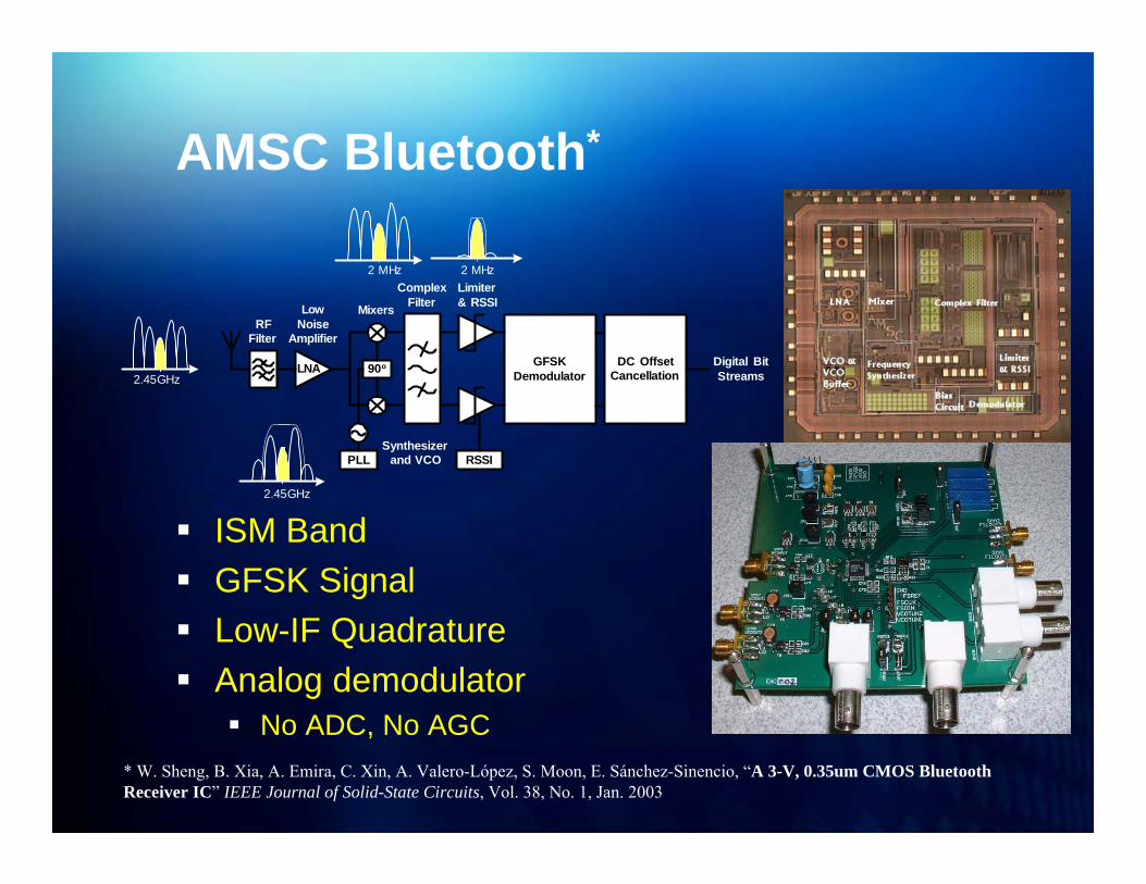
AMSC Bluetooth*
ISM BandGFSK SignalLow-IF QuadratureAnalog demodulator
No ADC, No AGC* W. Sheng, B. Xia, A. Emira, C. Xin, A. Valero-López, S. Moon, E. Sánchez-Sinencio, “A 3-V, 0.35um CMOS Bluetooth Receiver IC” IEEE Journal of Solid-State Circuits, Vol. 38, No. 1, Jan. 2003
LNA 90o
PLL
RFFilter
LowNoise
Amplifier
RSSISynthesizer
and VCO
ComplexFilter
GFSKDemodulator
DC OffsetCancellation
Mixers
Limiter& RSSI
Digital BitStreams2.45GHz
2.45GHz
2 MHz 2 MHz

Chameleon(Bluetooth/WiFi)
Applications

Standard comparison
Bluetooth Wi-Fi
RF Frequency 2.4GHz 2.4GHz
Sensitivity -70dBm -80dBm
Maximum Signal -20dBm -4dBm
Modulation GFSK CCK
Data rate 1Mb/s 1, 2, 5.5, 11Mb/s
Channel Bandwidth 1MHz 22MHz

Chameleon* (Wifi /Bluetooth)
Direct conversion allows for maximum block sharingShared RF front-end and programmable baseband componentsProgrammable channel selection filter with constant linearityAC coupled VGA with constant output offsetOn-chip time-interleaved pipeline ADC
* A. A. Emira, A. Valedes-Garcia, B. Xia, A. N. Mohieldin, A. Y. Valero-López, S. T. Moon, C. Xin, E. Sánchez-Sinencio, “Chameleon: A Dual-Mode 802.11b/Bluetooth Receiver System Design” IEEE Journal of Solid-State Circuits, Vol. 53, No. 5, May 2006

Ultra WidebandCommunication

Ultra-Wideband Communication
UWB ApplicationsCertified wireless USB
Hub and dongle adapter kitsEmbedded laptop solutionsReal Time Location System
Late take-off in 200740,000 units shipped in 2007400,000,000[1] predicted by 2013Tremendous potential in handsetsPossibility of integration w/ Bluetooth
[1] ABI Research prediction
Wireless USB (Courtesy of Belkin)
RTLS System (Courtesy of MultiSpectral Solutions)

Pulse-based UWB
Short burst of electromagnetic energyEfficient battery useMulti-path fading immunitySecureHigh Crest factor (PAR)Not immune to ISI
ApplicationsRadar/Imaging (1-100M Pulse/S)Precision Asset localizationRFIDCommunication (1-2G Pulse/S)
0 1 2 3 4 5 6 7 8 9 10 11 12 13 14Frequency [GHz]
Nor
mal
ized
-1 0 1Time [ns]
Nor
mal
ized

MB-OFDM UWB
7500 MHz divided into 14 bands of 528 MHzOnly first Band Group is mandatoryAll-band receiver is challenging
Range of frequencies to be generated spans several gigahertzSwitch time between different bands within band group should be less than 9.5ns
* C. Mishra, A. Valedes-Garcia, F. Bahmani, Anuj Batra, E. Sánchez-Sinencio, J. Silva-Martinez,“Frequency Planning and Synthesizer Architectures for Multiband OFDM UWB Radios” IEEE Transactions on Microwave Theory and Techniques, Vol. 53, No. 12, December 2005

AMSC UWB*
Direct Conversion ReceiverFull implementation from LNA to ADCIncludes on-chip rejection of interference in the 5.2GHz U-NII band (WLAN)On-Chip Synthesizer generates the 11 required carriers
* A. Valedes-Garcia, C. Mishra, F. Bahmani, J. Silva-Martinez, E. Sánchez-Sinencio, “An 11-Band 3-10 GHz Receiver in SiGeBiCMOS for Multiband OFDM UWB Communications” IEEE Journal of Solid-State Circuits, Vol. 42, No. 2, April 2007
`
LNA with5.2 GHz Notch PGA
PGALPF
LPF
I Q
11 Bands 3.7-10.1GHzFrequency Synthesizer
Linear PhaseAnalog Base Band
FixedPLL
Notchtuning
1 GS/s
6bit I&Q
ADCs
8.448GHz
528MHz
I&QMixer
PLL & VCO
LNA + Mixer& Notch Filter
FrequencySynthesizer
Filter VGA

Maximum conversion gain 78-67 dB
Noise figure across bands 5-10 dB
IIP3 for band group 1 (worst case) -9 dBm
Baseband group delay variation <0.6 nS
Active area 5.6 mm2 including pads
Current consumption 114 mA
Supply voltage 2.5 V
Package QFN
Technology IBM 6HP 0.25um SiGe
First 3-10GHz MB-OFDM UWB receiver.Features first 3-10GHz 11 band fast switching frequency synthesizer.First UWB receiver beyond 5GHz demonstrated in package
Highlight of Experimental Results
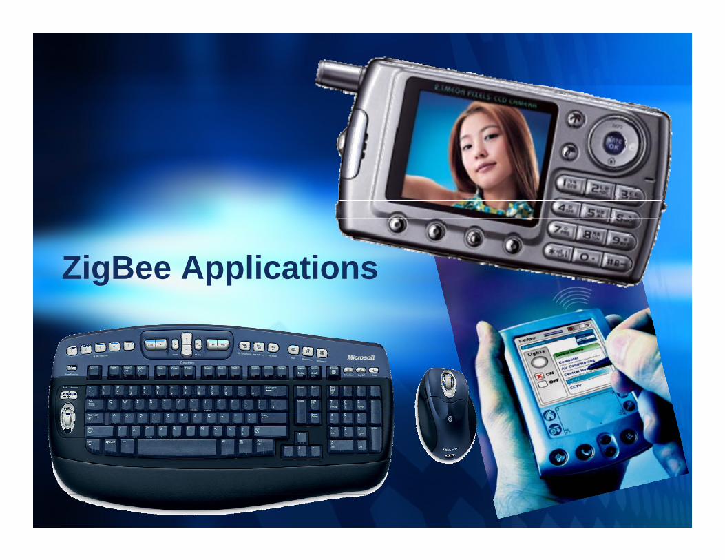
ZigBee Applications

AMSC ZigBee Transceiver*
Very low-power standardDirect Conversion / ISM BandOQPSK Signal w/ sine-wave shapingAnalog Mo/Dem
CoherentNon-Coherent
PA
LPF
LPF
1.5 MHz
1.5 MHz
LNA
QI
BPF
BPF
100 kHz -1.5 MHz
100 kHz -1.5 MHz
VGA
VGA
Moduator/
DemodulatorSynthesizer
I Q
* Under fabrication; Team Members: Faisal Hussien, Hesam A. Aslanzadah, Sang Wook Park, Didem Turker, Rangakrishnan Srinivasan, Felix Fernandez, Mohamed Mobarak, Gang Bu, Edgar Sánchez-Sinencio
Integer-N SynthesizerSwitching-Type PA
Constant-envelope signal

Recent Trendsin Wireless Technologies

Recent TrendsMulti-Standard Transceivers
Multifunctional, Multi-band, Concurrent radiosAdaptive Radios
Software-Defined RadioBaseband blocks
ReconfigurableProgrammablePower-Adjustable
High IntegrationAntenna integration at millimeter-wave frequencies
Wearable devicesUltra low-power reliable RF/Analog
MIMOIEEE 802.11n, WiMax, …

Emerging Technologies
Concept: Quantum tunnelingLow-Cost MIM technologyPhiar Inc. models fT of 1.8 THz for MIIMIM transistors to be produced in 2008“Amorphous and compatible with a wide range of substrate materials”
Single chip CMOS 60-GHz transceiver possible w/ digital CMOS and integrated antenna + front-end in MIM
Electron Tunneling used in a Diode(Source: Phiar.com)
Metal1 Metal2Insulator
-20 -10 0 10 20 30 40 50
Distance(A)
Bias Voltage
Ener
gy (e
v)
9.8
10.3
10.8
11.3
11.8

Emerging Technologies
Concept: Green WirelessNo Battery, No wireBuilding/Home/Industrial AutomationRadio Module
Energy Scavenging: 50uWRange: 300m (free field) / 30m(Building)868MHz (license free) / 315MHz (less crowded)Data rate: 125kbps
How?Avoid over-crowded ISM band (2.4GHz)ASK / 1% duty cycleMultiple short telegrams (1ms) w/ checksum
Torre Espacio Building,Madrid, is automated using self-powered wireless network of 4200 switches, 13500 addressable luminaries and 4500 blinds
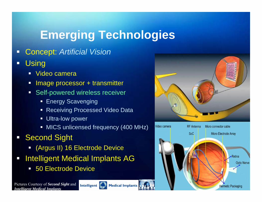
Emerging TechnologiesConcept: Artificial VisionUsing
Video cameraImage processor + transmitterSelf-powered wireless receiver
Energy ScavengingReceiving Processed Video DataUltra-low powerMICS unlicensed frequency (400 MHz)
Second Sight(Argus II) 16 Electrode Device
Intelligent Medical Implants AG 50 Electrode Device
Pictures Courtesy of Second Sight and Intelligent Medical Implants

Emerging Technologies
Wireless HD (High Definition)Three contenders:
UWB (MBOA)IEEE 802.11n60 GHz license-free waveband
4000/25000392500760 GHz74/24822400.67IEEE 802.11n200/480-45201.5 (1 BG)UWB
Data rate [Mbps]
Typ./Max.Pmax [dBm]
Channel BW[MHz]
Available Spectrum[GHz]

Medical Implant Communications Service*
* Under Tape-out; Team: Félix O. Fernández-Rodríguez, Mohamed S. Mobarak, Mohammed M. Abdul-Latif, Jincheng Li, KwisungYoo, Edgar Sánchez-Sinencio
Possible scenario where patient conditions can be addressed remotely in real time using both implanted
and wearable devices
`
Hospital
Implanted devices
Wearable devices
Wearable base station
Concept: Wearable Communication device$40B Market by 2011Implantable Medical Devices (IMD)
Heart diseasesNeurological disorders, …
402-405MHz band

LNA
LO
FrequencySynthezier
Mixer
Complex Image Rejection
Filter
Pre-Amplifier & Limitter
Demodulator
SAW Filter
Architecture:
Measured and simulated return loss for stacked implantable planar inverted-F antenna implanted into different biological tissue
Why 402-405 MHz?Good radio propagation characteristic within human body (less return loss)Suitable to meet MICS requirements (e.g. size, power, antenna performance and relaxed receiver design)
-106dBmSensitivity> 250 kbpsData rate

AMSC MM-wave Receiver*
Project GoalsDesign/Implementation of a dual band receiver for the ISM(24GHz)and LDMS(31GHz) bands The receiver should comply with IEEE802.16 standard
MM-wave Dual Band receiverThe RF front-end is reusedSub-harmonic mixing to reduce LO frequencyBand selection is preformed at IF
* Under Design; Team: Mohamed El-Nozahi, Ahmed Amer, Kamran Entesari and Edgar Sanchez-Sinencio

Conclusion
Wireless applications in all areas of our lives
Cartoons courtesy of The Economist (by Bell Mellor)
Medical, Environmental, Communication, House Automation, Security, …
Different architectures for varying applications

Thank YouQ&A