realistic antenna array modeling for 5g communications...mimic in hfss 3d layout 3d em simulation of...
TRANSCRIPT

Realistic Antenna Array Modeling for 5G Communications
Laila Salman, Fred.German, Safa Salman, Sergio Melais & Arien Sligar
ANSYS Inc.

The Evolution of the Network*
*https://www.akuaroworld.com/wp-content/uploads/2016/09/2do-arte-1.jpg
1980s - Basic voice Analog protocols
1990s - Voice using digital standards
2000s - Broadband IP protocol
2010s - Unified standards - LTE
2020s+ - New infrastructure - High speed and capacity

2020s+ - New infrastructure - High speed and capacity
So what do we expect from 5G?
• 5G will be everywhere • 5G and IoT go hand in hand • 5G must handle more users and even 4K data transfer
New Frequency (28 GHz)…. New Band …. New Problems!
Interference and Jamming
New infrastructure
Thermal issues and overheating
Detuning
Loss of connectivity and Network outage
Sensitivity to weather
Line of sight
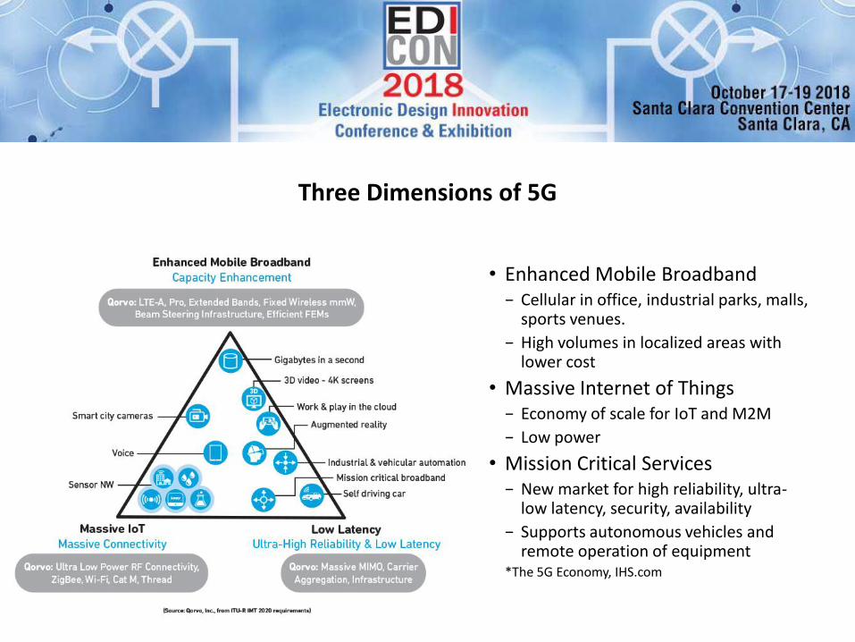
Three Dimensions of 5G
• Enhanced Mobile Broadband − Cellular in office, industrial parks, malls,
sports venues.
− High volumes in localized areas with lower cost
• Massive Internet of Things − Economy of scale for IoT and M2M
− Low power
• Mission Critical Services − New market for high reliability, ultra-
low latency, security, availability
− Supports autonomous vehicles and remote operation of equipment
*The 5G Economy, IHS.com

5G Active Antenna System: Multi-Scale + Multi-Domain
MIMIC in HFSS 3D Layout
3D EM Simulation of Amp Package
3D EM Simulation of Circulator
Antenna Element/Array
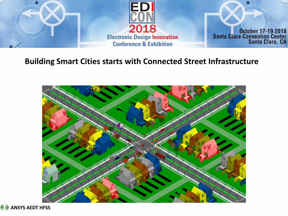
Building Smart Cities starts with Connected Street Infrastructure
ANSYS AEDT HFSS
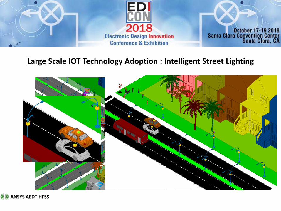
Large Scale IOT Technology Adoption : Intelligent Street Lighting
ANSYS AEDT HFSS

Unit Cell

Array Design Methodology
• Antenna Element Design
– Antenna element design
– Quickly predict performance when integrated into finite array
– Standalone antenna element, or unit cell (infinite array) analysis
8 Element Array Panel
128 Element Phased Array
Single Antenna Element
Multiple Array Panels integrated on Platform
Antenna with Radome Integration
• Finite Array Analysis
– Analysis of finite array to accurately capture all effects
– Edge effects, mutual coupling, active S-parameters
• Array Platform Integration and Performance
– Real world phased array performance including platform effects
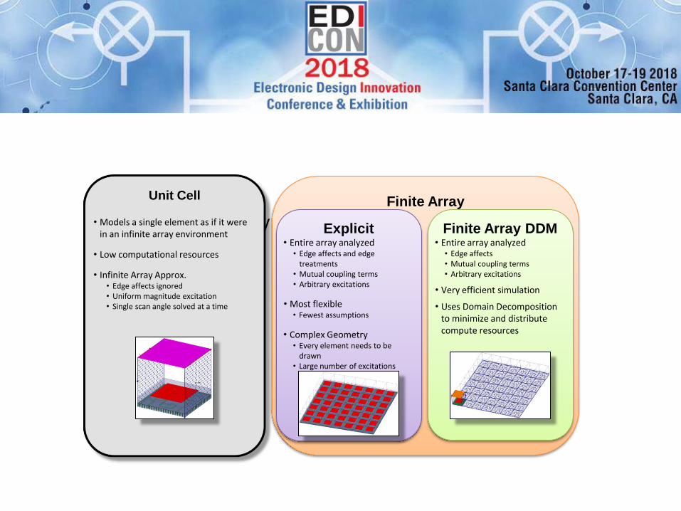
Array Analysis Approaches
Unit Cell
• Models a single element as if it were in an infinite array environment
• Low computational resources
• Infinite Array Approx. • Edge affects ignored • Uniform magnitude excitation • Single scan angle solved at a time
Finite Array
Explicit • Entire array analyzed
• Edge affects and edge treatments
• Mutual coupling terms • Arbitrary excitations
• Most flexible • Fewest assumptions
• Complex Geometry • Every element needs to be
drawn • Large number of excitations
Finite Array DDM • Entire array analyzed
• Edge affects • Mutual coupling terms • Arbitrary excitations
• Very efficient simulation
• Uses Domain Decomposition to minimize and distribute compute resources

Unit Cell
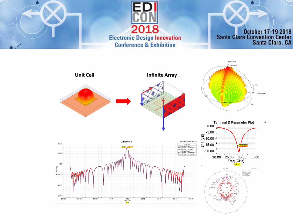
Unit Cell Infinite Array

Unit Cell Infinite Array
Finite Array DDM
256 element array
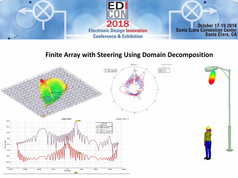
Finite Array with Steering Using Domain Decomposition
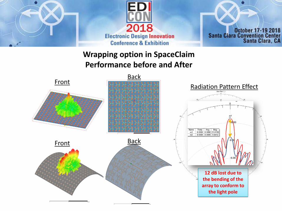
Wrapping option in SpaceClaim Performance before and After
Radiation Pattern Effect Front
Front
Back
Back
12 dB lost due to the bending of the array to conform to
the light pole

Array on Platform
Electrically large
environment (1400 λ)

HFSS Solver Overview
ANSYS Domain Decomposition Method
Savant: Shooting Bouncing Ray
ANSYS Domain Decomposition Method
Geometry and Material Complexity
Ele
ctri
cal S
ize
HFSS: Finite Elements
HFSS-IE: Fast Method of Moments
The ANSYS Solution
Geometry and Material Complexity
Ele
ctri
cal S
ize
HFSS: Finite Elements
HFSS-IE: Fast Method of Moments

In free space
Array on Platform Results
Far Field Link
and GPU Accelerated
with SBR+ Installed on Platform (Metal Pole)
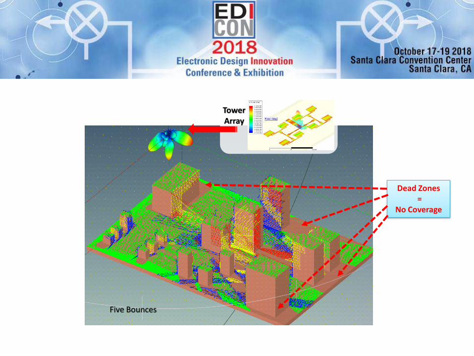
Shooting and bouncing rays Single bounce Two Bounces Three Bounces Four Bounces Five Bounces
Tower Array
Dead Zones =
No Coverage

Advanced Electromagnetic Solution for Electrically Large Geometry: Fully Coupled Hybrid Solution
Integral Equation, Physical Optics or Shooting Bouncing Ray –Tower Geometry
Finite Element Method for antenna array
Hybrid Solution Combining multiple numerical techniques in a hybrid solution allows for most efficient solution to this electrically large complex problem Fully coupled solutions
Coupling Matrix

Encrypted 3D Components
Original Antenna Simulation
Model
• Geometry may contains
sensitive IP that may make
it difficult/undesirable to
share with others
Encrypted Model
• Full fidelity of original model
encapsulated and encrypted
• Visibility of geometry and fields are
defined by original model creator
• 3D EM simulation
Installed Antenna Performance with
Encrypted Model
• Maintains accuracy and details of
original component, but without
exposing sensitive IP

Large Scale Simulations with SBR: Received signal strength evaluation
Position 1 Position 2 Position 3
Transmitter – Fixed Beam Antenna Array
Position 1
Position 2
Position 3
Receiver Location
Electrically very large, multi-path environment • Observation of fading effects as receiver travels
along path • Reduced signal strength as receiver travels in
direction with increased blockage • Fixed antenna

• 5G utilizes adaptive beamforming
• Enabling technology multi-user massive MIMO
• More efficient usage of radiated power
Adaptive Beamforming
Fixed Beam Array Antenna typical in 4G Adaptive Phased Array Antenna for 5G
• Fixed beam antenna systems – Limiting factor of many 3G/4G networks
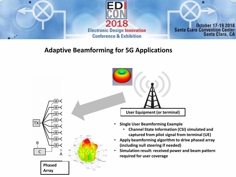
Adaptive Beamforming for 5G Applications
User Equipment (or terminal)
Phased Array
• Single User Beamforming Example • Channel State Information (CSI) simulated and
captured from pilot signal from terminal (UE) • Apply beamforming algorithm to drive phased array
(including null steering if needed) • Simulation result: received power and beam pattern
required for user coverage

Adaptive Beamforming: Line of Sight Example
• Demonstration of adaptive beamforming algorithm implemented using a hybrid FEM-SBR solution − Phased array (Base station) solved using
faDDM
− Separation between UE and Base Station simulated using SBR solver
• 100 meter separation at 28GHz (10,000λ)
User Equipment
Base Station
Base Station Gain Spherical
Plot

Adaptive Beamforming: Non-Line of Sight Example
• Demonstration of adaptive beamforming algorithm for dynamic scenario where LoS is temporarily blocked − Metal plate used to provide blockage
and multi-path propagation potential
− Secondary beam seen when plates transition across line of sight
Metal Objects

Large Scale Simulation for 5G (28GHz) Base Station Performance
• Physics based simulation of large scale environments − Shooting Bouncing Ray (SBR) for efficient
simulation of electrically large environment.
− Accurate representation of antenna array through FEM simulation
• Evaluate system performance − Antenna Array
− Site evaluation
− Beamforming, null steering algorithms
− Received power at user equipment
− Base station to base station interference or unintentional jamming
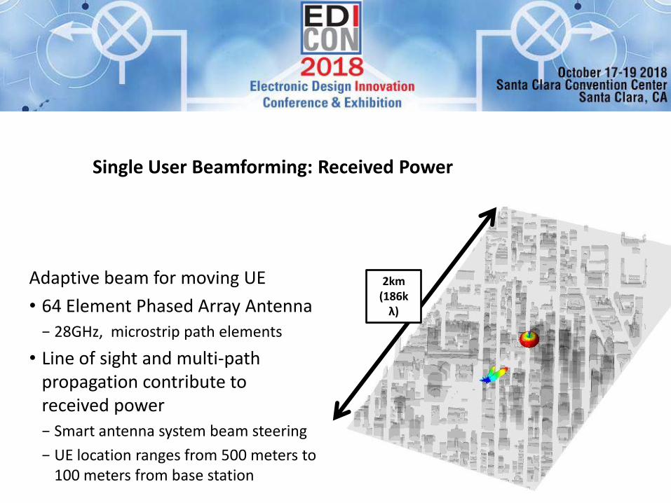
Single User Beamforming: Received Power
Adaptive beam for moving UE
• 64 Element Phased Array Antenna
− 28GHz, microstrip path elements
• Line of sight and multi-path propagation contribute to received power
− Smart antenna system beam steering
− UE location ranges from 500 meters to 100 meters from base station
2km (186k
λ)

UE Received Power for Adaptive Antenna Array
• Power received by UE for path along city street
• Single user adaptive beamforming, no interference − Includes multi-path propagation
− Up to 7 bounces (SBR solution setting)

Base Station Handoff
• Device travels along street in dense urban environment
• UE travels between coverage zones of two base stations − Observe received power from both
sites
• Site evaluation
• Base Station to Base Station Interference
Base Station Antenna Array 1
Base Station Antenna Array 2
Device traveling 0.5km in dense urban environment

Base Station Handoff: Received Power and Coverage Zones
Base stations approximate cell coverage zones
Base Station 2 Base Station 1
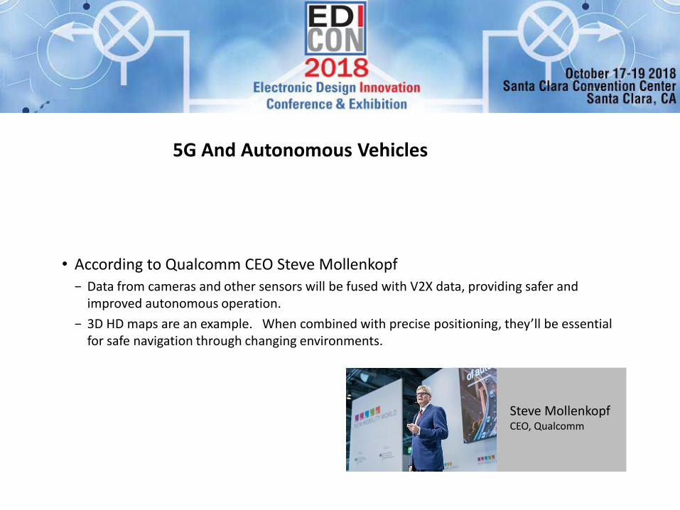
5G And Autonomous Vehicles
• According to Qualcomm CEO Steve Mollenkopf − Data from cameras and other sensors will be fused with V2X data, providing safer and
improved autonomous operation.
− 3D HD maps are an example. When combined with precise positioning, they’ll be essential for safe navigation through changing environments.
Steve Mollenkopf CEO, Qualcomm
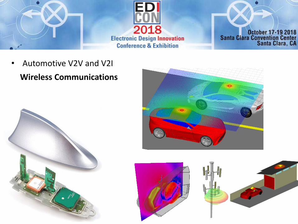
Wireless Communications
• Automotive V2V and V2I

Engineering Design Challenges facing the IoT V2V Communication Systems …
ANSYS AEDT HFSS / RF Option (EMIT)
DSRC Ceramic Patch Antenna (5.9 GHz)
DSRC radios easily configured from standards-based Wi-Fi library models
Propagation models provide rapid path-loss calculations for a variety of environments and conditions

Environment Effects on V2V Links
5.9 GHz Antenna System Simulations

Thank You!!!
• Connect with Me
• Connect with ANSYS, Inc.
– LinkedIn ANSYSInc
– Twitter @ANSYS_Inc
– Facebook ANSYSInc
• Follow our Blog ansys-blog.com