real -time object detectio n, tracking , and 3d ... · real -time object detectio n, tracking , and...
TRANSCRIPT

REAL-TIME OBJECT DETECTION, TRACKING, AND 3D POSITIONING IN A MULTIPLE CAMERA SETUP
Y. J. Lee *, A. Yilmaz
Dept. of Civil, Environmental and Geodetic Engineering, The Ohio State University, Columbus, Ohio, USA –
(lee.3043, yilmaz.15)@osu.edu
Commission III, WG III/3
KEY WORDS: Multiple camera tracking, multi- camera detection, real-time positioning ABSTRACT: We introduce a real-time object positioning system that naturally combines detection, tracking, and 3D positioning in a multiple camera setup. Depending on the task, the detection, tracking, and positioning steps, when performed independently have limitations due to the loss of temporal and geometric constraints. We conjecture that the detection and tracking steps do not always estimate a correct solution due to incorrect matches, appearance variations or occlusions. In order to offset these problems, we use the geometry between the target object and cameras to refine detection and tracking result and provide persistent and reliable solution to 3D positioning. The geometry is introduced to the detection and tracking steps by simultaneously solving the 3D position of the target object by using a bundle adjustment step. Test results show that the system provides reliable solution at the speed of six to ten frames per second for a four high definition camera setup running on a single computer.
* Corresponding author.
1. INTRODUCTION
Real-time multi-camera object tracking and 3D positioning have many applications such as in automated surveillance (Qu, et al., 2007) and objects monitoring (Krumm, et al., 2000), yet it remains a challenging research task (Straw, et al., 2011). Although, there is a large number of object detection and tracking algorithms, most of them have limitations related to appearance variations and occlusions. Solving object detection, tracking, and positioning simultaneously in a multiple high definition camera setup is not an easy task and requires efficient algorithmic development. This constraint has resulted in a small number of articles published on 3D tracking. The earliest study on the topic dates back to Krumm, et al.’s (2000) study that performed multi-person tracking by using two sets of stereo cameras. They performed tracking on three computers; two of which are used to process the stero cameras and the other computer is used to combine the two independent results. The processing speed of their implementaion was 3.5 frames per second (fps). In Qu, et al. (2007), the multi camera multi-target tracking is performed by using a bayesian framework to overcome occlusions problem of mutiple targets. In another work, Straw, et al (2011) introduced the real-time multi-camera 3D tracking system to track insects. Their method used an extended Kalman filter and the nearest neighbor association for matching insects. One of their setups consisted of eleven inexpensive standard definition cameras and nine computers for processing camera outputs. The processing speed of their implementaion was 60 fps. In this paper, we design a real time object tracking system that naturally combines detection, tracking and precise 3D positioning by means of multiple camera geometry. The object detection and tracking steps reliably finds the target object
position in the images, which are refined by imposing the geometric relations between the cameras. Our system setup consists of a laptop computer and four high definition cameras connected to the computer. In contrast to earlier studies, our goal in this paper is to estimate precise 3D object location in real time. In order to realize this, we fuse the result of detection and tracking steps with geometric constraints defined between multiple cameras. In particular, the geometry serves as a quality indicator for the detection or tracking results and can be used to automatically recognize and correct errors during occlusions. The limitation of our current implementation is that the proposed method works for only a single target with a specially designed marker. Test result shows that the system provides precise 3D position of the target object automatically at 10 frames per second when all four cameras are online. The rest of this paper is organized as follows. Sec. 2 introduces the system configuration; Sec. 3 provides detailed discussions on detection, tracking, and refinement processes; Sec. 4 presents experimental results; and Sec. 5 conclusions the paper.
2. SYSTEM CONFIGURATION
The system that implements the proposed approach consists of a processing computer, four high definition Gigabit Ethernet (GigE) cameras, and a Gigabit Ethernet switch (see Figure 1). The four cameras are placed on the opposite corners of the site to reduce object occlusions and provide better geometry with wide baseline. In real time processing the data transmit-rate is an important system parameter. Because of this, while the cameras can be connected via wireless network, we chose a wired network for the four Gigabit Ethernet Vision cameras. The GigE vision
ISPRS Annals of the Photogrammetry, Remote Sensing and Spatial Information Sciences, Volume II-3/W2, 2013ISA13 - The ISPRS Workshop on Image Sequence Analysis 2013, 11 November 2013, Antalya, Turkey
This contribution has been peer-reviewed. The double-blind peer-review was conducted on the basis of the full paper. 31

camera uses the Ethernet communication protocol that transmits data up to 125MB/s and via up to 100 meter cable. The 125MB/s data transmit rate enables to use up to a maximum of four cameras for real-time processing. The camera selected for this system provides 1292×964 resolution with up to 30 fps frame rate.
Figure 1. System configuration
The interior and exterior orientations of the cameras are estimated using photogrammetric process. In particular, we calibrated the lenses using self-calibration method for fixed focal lens cameras. The elements of exterior orientation, which include the spatial position and angular orientation of an image (Wolf & Dewitt, 2000), are estimated by using bundle adjustment. The targets used for the exterior orientation are installed on the wall of the target area and its 3D coordinates are precisely measured by a total station. 2.1 Time Synchronization of Cameras and Frame Rate
Time synchronization between the cameras is important for acquiring images at the same time epoch and estimating 3D coordinates of a moving object. In our implementation, we used software triggering, which sends request to all cameras simultaneously and receives time synchronized images from the cameras. The frame rate in this set up is defined based on the image acquisition delay and processing delay. The image transmission time is negligible due to the fact it is significantly smaller than the former two delays. The acquisition delay depends on the exposure time which is related to the environment lighting to acquire a clean image. Therefore, the optimal exposure time that compromises between a good frame rate and an acceptable image quality is chosen prior to processing images.
Figure 2. Target object (yellow box) and its templates
3. DETECTION, TRACKING AND REFINEMENT
We define detection as the process of finding object of interest in an image without knowing its prior position in the previous frame while tracking is defined as the process that estimates object location based on the object’s position in the previous frame. In the following discussion, we will give details of these
steps as well as the geometric refinement of detection and tracking for reliable positioning of the target object. We will start the discussion by introducing the object we are interested in estimating precise 3D location.
3.1 The Target Object
Our goal in this paper is precise location of a construction tool as shown in Figure 2 (left). In order to offset appearance variation with viewpoint changes, we detect and track part of the object which appears the same from different directions. In order to facilitate this, we designed the object shown in Figure 2 (yellow box), which is a series of black, white and black stripes. In this setup, the target object can be detected by using special templates, which are scale and rotation invariant (see right in Figure 2 for examples). Note that, an alternative method is to use a single template (potentially generated from the objects appearance in the first frame) and detect/track the object by minimizing a cost function, which contains scale and rotation as its parameters. This treatment, however, is computationally more expensive than using multiple templates; hence, our choice is due to the real time processing needs. The special templates are generated to overcome scale changes in the object. Each scaled template set is associated with multiple rotated templates generated from different rotation angles. Number of scale sets is calculated based on the maximum and minimum distances of the object from the cameras. Rotation angle interval between templates is set to ten degrees. 3.2 Detection
Considering the resolution of the acquired images (1292×964) and use of no prior location information, the detection step is the most time consuming task of the proposed system. In order to reduce the search space, we use background subtraction to reduce the object search to only the moving regions in the image. The search for the object is then performed via image matching. The background subtraction process labels every pixel in the image into foreground and background. The labeling is achieved by generating a background model and testing pixels against the model to verify if they satisfy the model. The pixels that do not satisfy the model become the foreground pixels and correspond to the moving regions in the image. The literature contains different models to address illumination variations and dynamic backgrounds. In our paper, we adopted the mixture of Gaussians model which uses linear combination of Gaussians. The labeled foreground pixels are conjectured to contain the object of interest. Within the region labeled as foreground, the location of the object of interest is detected via template matching. We particularly choose cross-correlation as the similarity measure. Prior to finding the target, it is important to predict the scale of the target object to reduce template search time. In our implementation, the search for the template is governed by first using the estimated 3D coordinates of the target object in the previous frame. This estimation process provides a means to compute the scales for each camera. Once the scales are known, we perform template matching for all rotation angles in that scale to find the best match. Following the template matching step, a refinement process assesses
ISPRS Annals of the Photogrammetry, Remote Sensing and Spatial Information Sciences, Volume II-3/W2, 2013ISA13 - The ISPRS Workshop on Image Sequence Analysis 2013, 11 November 2013, Antalya, Turkey
This contribution has been peer-reviewed. The double-blind peer-review was conducted on the basis of the full paper. 32
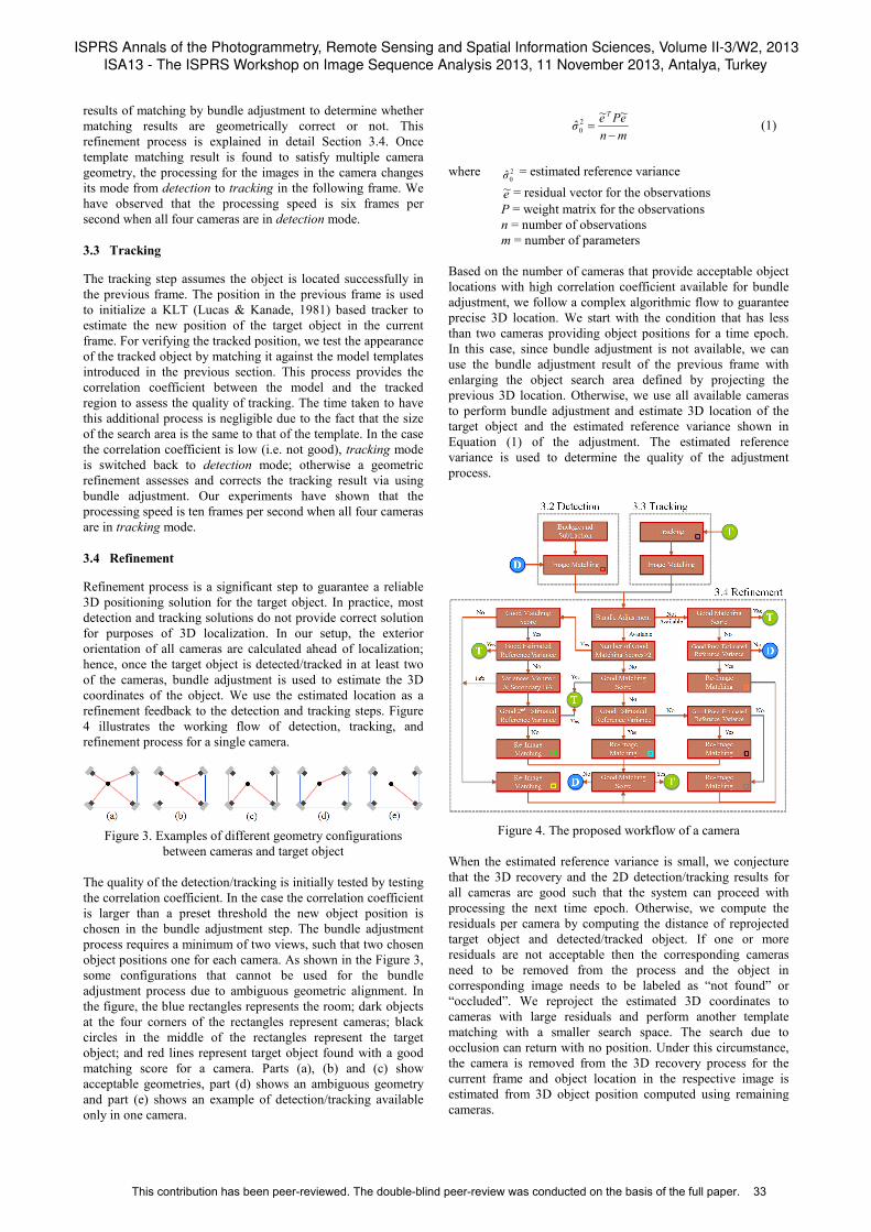
results of matching by bundle adjustment to determine whether matching results are geometrically correct or not. This refinement process is explained in detail Section 3.4. Once template matching result is found to satisfy multiple camera geometry, the processing for the images in the camera changes its mode from detection to tracking in the following frame. We have observed that the processing speed is six frames per second when all four cameras are in detection mode. 3.3 Tracking
The tracking step assumes the object is located successfully in the previous frame. The position in the previous frame is used to initialize a KLT (Lucas & Kanade, 1981) based tracker to estimate the new position of the target object in the current frame. For verifying the tracked position, we test the appearance of the tracked object by matching it against the model templates introduced in the previous section. This process provides the correlation coefficient between the model and the tracked region to assess the quality of tracking. The time taken to have this additional process is negligible due to the fact that the size of the search area is the same to that of the template. In the case the correlation coefficient is low (i.e. not good), tracking mode is switched back to detection mode; otherwise a geometric refinement assesses and corrects the tracking result via using bundle adjustment. Our experiments have shown that the processing speed is ten frames per second when all four cameras are in tracking mode. 3.4 Refinement
Refinement process is a significant step to guarantee a reliable 3D positioning solution for the target object. In practice, most detection and tracking solutions do not provide correct solution for purposes of 3D localization. In our setup, the exterior orientation of all cameras are calculated ahead of localization; hence, once the target object is detected/tracked in at least two of the cameras, bundle adjustment is used to estimate the 3D coordinates of the object. We use the estimated location as a refinement feedback to the detection and tracking steps. Figure 4 illustrates the working flow of detection, tracking, and refinement process for a single camera.
Figure 3. Examples of different geometry configurations
between cameras and target object The quality of the detection/tracking is initially tested by testing the correlation coefficient. In the case the correlation coefficient is larger than a preset threshold the new object position is chosen in the bundle adjustment step. The bundle adjustment process requires a minimum of two views, such that two chosen object positions one for each camera. As shown in the Figure 3, some configurations that cannot be used for the bundle adjustment process due to ambiguous geometric alignment. In the figure, the blue rectangles represents the room; dark objects at the four corners of the rectangles represent cameras; black circles in the middle of the rectangles represent the target object; and red lines represent target object found with a good matching score for a camera. Parts (a), (b) and (c) show acceptable geometries, part (d) shows an ambiguous geometry and part (e) shows an example of detection/tracking available only in one camera.
mnePeσ
T
−=
~~ˆ 2
0 (1)
where 2
0σ̂ = estimated reference variance e~ = residual vector for the observations P = weight matrix for the observations n = number of observations m = number of parameters Based on the number of cameras that provide acceptable object locations with high correlation coefficient available for bundle adjustment, we follow a complex algorithmic flow to guarantee precise 3D location. We start with the condition that has less than two cameras providing object positions for a time epoch. In this case, since bundle adjustment is not available, we can use the bundle adjustment result of the previous frame with enlarging the object search area defined by projecting the previous 3D location. Otherwise, we use all available cameras to perform bundle adjustment and estimate 3D location of the target object and the estimated reference variance shown in Equation (1) of the adjustment. The estimated reference variance is used to determine the quality of the adjustment process.
Figure 4. The proposed workflow of a camera
When the estimated reference variance is small, we conjecture that the 3D recovery and the 2D detection/tracking results for all cameras are good such that the system can proceed with processing the next time epoch. Otherwise, we compute the residuals per camera by computing the distance of reprojected target object and detected/tracked object. If one or more residuals are not acceptable then the corresponding cameras need to be removed from the process and the object in corresponding image needs to be labeled as “not found” or “occluded”. We reproject the estimated 3D coordinates to cameras with large residuals and perform another template matching with a smaller search space. The search due to occlusion can return with no position. Under this circumstance, the camera is removed from the 3D recovery process for the current frame and object location in the respective image is estimated from 3D object position computed using remaining cameras.
ISPRS Annals of the Photogrammetry, Remote Sensing and Spatial Information Sciences, Volume II-3/W2, 2013ISA13 - The ISPRS Workshop on Image Sequence Analysis 2013, 11 November 2013, Antalya, Turkey
This contribution has been peer-reviewed. The double-blind peer-review was conducted on the basis of the full paper. 33
Index Classification of a match
Detection
Tracking
Refined match which had a good matching score as well as large residual when # of good scores>2 by current frame geometry
Refined match which had a not good matching score when # of good scores>2 by current frame geometry
Refined match which had a not good matching score when # of good scores=2 by current frame geometry
Refined match which had a not good matching score when # of good scores<2 by previous frame geometry
Refined match which had a not good matching score when # of good scores=2 by previous frame geometry
Refined match which had a not good matching score when # of good scores=2 by no geometry
Table 1. Classification of a match We should note that not all observations with large residuals are incorrect. These observations are due to a possible incorrect observation increasing the residuals of the correct observations. In other words, a match with large residual also can be a correct match. In this case, we find correct observations by performing a secondary bundle adjustment on different sets of images and monitoring their estimated reference variances. The camera sets with the lowest estimated reference variance is chosen as the set of true matches. In this step, 3D coordinates and it confidences of the target object are reestimated from the set and are used to guide the template search for the camera with large residuals.
4. EXPERIMENT
We designed and implemented a real-time system as a proof of concept for the algorithmic layout. Program is implemented in C++ language with parallel processing and testing environment is Window 7 running on a laptop computer with Intel i7-3632QM CPU and 16GB RAM. Target area is an 8m×5m×2.5m room and four GigE cameras installed at the each corner of the room. The implemented system estimates position of the target object about 6 to 10 fps processing speed. Note that FPS values in Figure 6~9 do not reflect the real-time values as the results are generated offline for the sake of providing visual results in this paper.
Figure 5. Legend for the screenshots; Camera ID (left) and
information on a single camera screen (right)
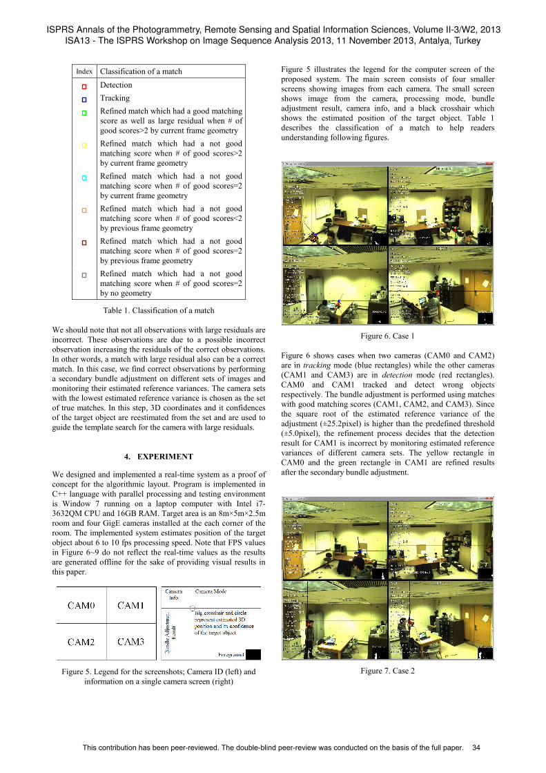
Figure 5 illustrates the legend for the computer screen of the proposed system. The main screen consists of four smaller screens showing images from each camera. The small screen shows image from the camera, processing mode, bundle adjustment result, camera info, and a black crosshair which shows the estimated position of the target object. Table 1 describes the classification of a match to help readers understanding following figures.
Figure 6. Case 1
Figure 6 shows cases when two cameras (CAM0 and CAM2) are in tracking mode (blue rectangles) while the other cameras (CAM1 and CAM3) are in detection mode (red rectangles). CAM0 and CAM1 tracked and detect wrong objects respectively. The bundle adjustment is performed using matches with good matching scores (CAM1, CAM2, and CAM3). Since the square root of the estimated reference variance of the adjustment (±25.2pixel) is higher than the predefined threshold (±5.0pixel), the refinement process decides that the detection result for CAM1 is incorrect by monitoring estimated reference variances of different camera sets. The yellow rectangle in CAM0 and the green rectangle in CAM1 are refined results after the secondary bundle adjustment.
Figure 7. Case 2
ISPRS Annals of the Photogrammetry, Remote Sensing and Spatial Information Sciences, Volume II-3/W2, 2013ISA13 - The ISPRS Workshop on Image Sequence Analysis 2013, 11 November 2013, Antalya, Turkey
This contribution has been peer-reviewed. The double-blind peer-review was conducted on the basis of the full paper. 34
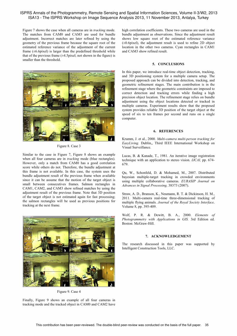
Figure 7 shows the case when all cameras are in tracking mode. The matches from CAM0 and CAM3 are used for bundle adjustment. Incorrect matches are later refined by using the geometry of the previous frame because the square root of the estimated reference variance of the adjustment of the current frame (±6.6pixel) is larger than the predefined threshold while that of the previous frame (±4.5pixel; not shown in the figure) is smaller than the threshold.
Figure 8. Case 3
Similar to the case in Figure 7, Figure 8 shows an example when all four cameras are in tracking mode (blue rectangles). However, only a match from CAM0 has a good correlation score while others do not. Therefore, the bundle adjustment at this frame is not available. In this case, the system uses the bundle adjustment result of the previous frame when available since it can be assume that the motion of the target object is small between consecutives frames. Salmon rectangles in CAM1, CAM2, and CAM3 show refined matches by using the adjustment result of the previous frame. Note that 3D position of the target object is not estimated again for fast processing; the salmon rectangles will be used as previous positions for tracking at the next frame.
Figure 9. Case 4
Finally, Figure 9 shows an example of all four cameras in tracking mode and the tracked object in CAM0 and CAM2 have
high correlation coefficients. These two cameras are used in the bundle adjustment as observations. Since the adjustment result shows low square root of the estimated reference variance (±0.6pixel), the adjustment result is used to refine 2D object location in the other two cameras. Cyan rectangles in CAM1 and CAM3 show refined result.
5. CONCLUSIONS
In this paper, we introduce real-time object detection, tracking, and 3D positioning system for a multiple camera setup. The proposed approach can be divided into detection, tracking, and geometric refinement stages. The main contribution is in the refinement stage where the geometric constraints are imposed to correct detection and tracking errors while finding a high precision object location. The refinement stage relies on bundle adjustment using the object locations detected or tracked in multiple cameras. Experiment results show that the proposed system provides reliable 3D position of the target object at the speed of six to ten frames per second and runs on a single computer.
6. REFERENCES
Krumm, J. et al., 2000. Multi-camera multi-person tracking for EasyLiving. Dublin,, Third IEEE International Workshop on Visual Surveillance. Lucas, B. & Kanade, T., 1981. An iterative image registration technique with an application to stereo vision. IJCAI, pp. 674-679. Qu, W., Schonfeld, D. & Mohamed, M., 2007. Distributed bayesian multiple-target tracking in crowded environments using multiple collaborative cameras. EURASIP Journal on Advances in Signal Processing, 38373 (2007). Straw, A. D., Branson, K., Neumann, R. T. & Dickinson, H. M., 2011. Multi-camera real-time three-dimensional tracking of multiple flying animals. Journal of the Royal Society Interface, Volume 8, pp. 395-409. Wolf, P. R. & Dewitt, B. A., 2000. Elements of Photogrammetry with Applications in GIS. 3rd Edition ed. Boston: McGraw-Hill.
7. ACKNOWLEDGEMENT
The research discussed in this paper was supported by Intelligent Construction Tools, LLC.
ISPRS Annals of the Photogrammetry, Remote Sensing and Spatial Information Sciences, Volume II-3/W2, 2013ISA13 - The ISPRS Workshop on Image Sequence Analysis 2013, 11 November 2013, Antalya, Turkey
This contribution has been peer-reviewed. The double-blind peer-review was conducted on the basis of the full paper. 35