real-time communication systems for small autonomous robots · real-time communication systems for...
TRANSCRIPT

Diplomarbeit
Real-time CommunicationSystems for
Small Autonomous Robots
ausgefuhrt zum Zwecke der Erlangung desakademischen Grades eines Diplom - Ingenieurs am
Institut fur Computertechnik 384 der
Technischen Universitat Wien
unter der Leitung von
O. Univ. - Prof. Dr. Dietmar Dietrich
und
Univ.Ass. Dr. Stefan Mahlknecht
Univ.Ass. Dr. Wilfried Elmenreich
als verantwortlich mitwirkende Assistenten durch
Stefan KrywultMatr. - Nr. 9827121
Anton-Bosch-Gasse 4/Stg. 1/5, 1210 Wien
Wien, im Oktober 2006 . . . . . . . . . . . . . . . . . . . . . . . . . . . . . . . . .

Abstract
Autonomous systems perform complex tasks to analyse and to react ontheir environment. One way to handle this complexity is distributing thefunctionality on several hardware modules. Even in small autonomoussystems the predictability of the communication and the synchronization ofall modules is vitally important.
This thesis provides a survey of five protocols that play a major role inthe automotive industry and in the domain of real-time communication:CAN, LIN, Flexray, TTP/C, and TTP/A. The protocols are compared andanalysed regarding their suitability for small autonomous systems.
Following the results of this investigation, TTP/A is ported to the hard-ware of the Tinyphoon robot, a research platform for small autonomous anddistributed systems. On the basis of the outcome of the case study enhance-ments and adoptions of TTP/A are proposed. To address the diversity ofhardware a general concept of making TTP/A more portable is elaborated.
1

Kurzfassung
Autonome Systeme analysieren ihr Umfeld und reagieren entsprechenddarauf. Um die Komplexitat dieser Funktionalitat besser handhabbar zumachen, wird sie auf mehrere Hardwaremodule aufgeteilt. Auch fur kleineautonome Systeme sind die Vorhersagbarkeit der Kommunikation zwischendiesen Modulen und die Synchronisierung des gesamten Systems von großerBedeutung.
Diese Arbeit beschreibt die Protokolle CAN, LIN, Flexray, TTP/C undTTP/A, die in der Automobilindustrie und im Bereich der Echtzeitkom-munikation eine wichtige Rolle spielen und vergleicht sie bezuglich ihrerVerwendbarkeit fur kleine autonome Systeme.
Den Resultaten dieser Untersuchung entsprechend wird TTP/A auf dieHardware des Tinyphoon Roboters, eine Forschungsplattform fur kleine au-tonome und verteilte Systeme, portiert. Basierend auf den Ergebnissen dieserFallstudie werden Erweiterungen und Anpassungen fur TTP/A vorgeschla-gen. Um der Vielfaltigkeit der Hardware in verteilten Systemen Rechnung zutragen, wird ein Konzept erstellt, wie die aktuelle TTP/A Implementierungportabler gestaltet werden kann.
2

Contents
Contents i
List of Figures iv
List of Tables v
List of Listings vi
1 Introduction 11.1 Background . . . . . . . . . . . . . . . . . . . . . . . . . . . . 11.2 Problem Statements ... . . . . . . . . . . . . . . . . . . . . . . 21.3 Outline of Thesis . . . . . . . . . . . . . . . . . . . . . . . . . 3
2 Real-time Protocols 42.1 Concepts . . . . . . . . . . . . . . . . . . . . . . . . . . . . . 4
2.1.1 Basic Terms . . . . . . . . . . . . . . . . . . . . . . . . 42.1.2 Real-Time . . . . . . . . . . . . . . . . . . . . . . . . . 62.1.3 Fault Tolerance . . . . . . . . . . . . . . . . . . . . . . 7
2.2 CAN . . . . . . . . . . . . . . . . . . . . . . . . . . . . . . . . 72.2.1 Mode of Operation . . . . . . . . . . . . . . . . . . . . 72.2.2 Additional Services . . . . . . . . . . . . . . . . . . . . 82.2.3 Packet Format . . . . . . . . . . . . . . . . . . . . . . 92.2.4 Data Encoding . . . . . . . . . . . . . . . . . . . . . . 112.2.5 Physical Layer . . . . . . . . . . . . . . . . . . . . . . 112.2.6 Real-Time Extensions . . . . . . . . . . . . . . . . . . 122.2.7 Efficiency . . . . . . . . . . . . . . . . . . . . . . . . . 142.2.8 Availability . . . . . . . . . . . . . . . . . . . . . . . . 15
2.3 LIN . . . . . . . . . . . . . . . . . . . . . . . . . . . . . . . . 162.3.1 Mode of Operation . . . . . . . . . . . . . . . . . . . . 162.3.2 Additional Services . . . . . . . . . . . . . . . . . . . . 172.3.3 Frame Format . . . . . . . . . . . . . . . . . . . . . . 182.3.4 Data Encoding . . . . . . . . . . . . . . . . . . . . . . 192.3.5 Physical Layer . . . . . . . . . . . . . . . . . . . . . . 192.3.6 Host Interface . . . . . . . . . . . . . . . . . . . . . . . 20
i
2.3.7 Efficiency . . . . . . . . . . . . . . . . . . . . . . . . . 202.3.8 Availability . . . . . . . . . . . . . . . . . . . . . . . . 21
2.4 Flexray . . . . . . . . . . . . . . . . . . . . . . . . . . . . . . 212.4.1 Mode of Operation . . . . . . . . . . . . . . . . . . . . 212.4.2 Additional Services . . . . . . . . . . . . . . . . . . . . 252.4.3 Frame Format . . . . . . . . . . . . . . . . . . . . . . 262.4.4 Data Encoding . . . . . . . . . . . . . . . . . . . . . . 282.4.5 Physical Layer . . . . . . . . . . . . . . . . . . . . . . 292.4.6 Host Interface . . . . . . . . . . . . . . . . . . . . . . . 302.4.7 Efficiency . . . . . . . . . . . . . . . . . . . . . . . . . 302.4.8 Availability . . . . . . . . . . . . . . . . . . . . . . . . 31
2.5 TTP/C . . . . . . . . . . . . . . . . . . . . . . . . . . . . . . 312.5.1 Mode of Operation . . . . . . . . . . . . . . . . . . . . 322.5.2 Additional Services . . . . . . . . . . . . . . . . . . . . 352.5.3 Frame Format . . . . . . . . . . . . . . . . . . . . . . 372.5.4 Data Encoding . . . . . . . . . . . . . . . . . . . . . . 382.5.5 Physical Layer . . . . . . . . . . . . . . . . . . . . . . 392.5.6 Host Interface . . . . . . . . . . . . . . . . . . . . . . . 392.5.7 Efficiency . . . . . . . . . . . . . . . . . . . . . . . . . 402.5.8 Availability . . . . . . . . . . . . . . . . . . . . . . . . 41
2.6 TTP/A . . . . . . . . . . . . . . . . . . . . . . . . . . . . . . 412.6.1 Mode of Operation . . . . . . . . . . . . . . . . . . . . 422.6.2 Additional Services . . . . . . . . . . . . . . . . . . . . 432.6.3 Frame Format . . . . . . . . . . . . . . . . . . . . . . 452.6.4 Data Encoding . . . . . . . . . . . . . . . . . . . . . . 462.6.5 Physical Layer . . . . . . . . . . . . . . . . . . . . . . 462.6.6 Application Interface . . . . . . . . . . . . . . . . . . . 472.6.7 Efficiency . . . . . . . . . . . . . . . . . . . . . . . . . 472.6.8 Availability . . . . . . . . . . . . . . . . . . . . . . . . 48
2.7 Other Protocols . . . . . . . . . . . . . . . . . . . . . . . . . . 482.7.1 Real-time Ethernet . . . . . . . . . . . . . . . . . . . . 482.7.2 USB . . . . . . . . . . . . . . . . . . . . . . . . . . . . 49
2.8 Comparison . . . . . . . . . . . . . . . . . . . . . . . . . . . . 50
3 Tinyphoon 553.1 Subsystems . . . . . . . . . . . . . . . . . . . . . . . . . . . . 57
3.1.1 Motion Unit . . . . . . . . . . . . . . . . . . . . . . . 573.1.2 Vision Unit . . . . . . . . . . . . . . . . . . . . . . . . 593.1.3 Decision Making Unit . . . . . . . . . . . . . . . . . . 60
3.2 Communication . . . . . . . . . . . . . . . . . . . . . . . . . . 603.2.1 Data Provided/Needed by the Subunits . . . . . . . . 603.2.2 Real-Time Requirements . . . . . . . . . . . . . . . . . 613.2.3 Fault Tolerance / Dependability Requirements . . . . 623.2.4 Data Throughput . . . . . . . . . . . . . . . . . . . . . 63
ii
3.2.5 Maintainability . . . . . . . . . . . . . . . . . . . . . . 633.2.6 Debugging and Monitoring . . . . . . . . . . . . . . . 633.2.7 Cost . . . . . . . . . . . . . . . . . . . . . . . . . . . . 643.2.8 Implementation Effort . . . . . . . . . . . . . . . . . . 643.2.9 Comprehensibility of Interfaces . . . . . . . . . . . . . 64
4 Analysis 654.1 Current Communication . . . . . . . . . . . . . . . . . . . . . 654.2 Features vs. Complexity . . . . . . . . . . . . . . . . . . . . . 664.3 HW Versus SW . . . . . . . . . . . . . . . . . . . . . . . . . . 664.4 RT Communication in SW . . . . . . . . . . . . . . . . . . . . 67
4.4.1 Time-Triggered CAN . . . . . . . . . . . . . . . . . . . 674.4.2 LIN . . . . . . . . . . . . . . . . . . . . . . . . . . . . 684.4.3 TTP/A . . . . . . . . . . . . . . . . . . . . . . . . . . 68
4.5 Results . . . . . . . . . . . . . . . . . . . . . . . . . . . . . . . 69
5 TTP/A on the Tinyphoon 705.1 Existing TTP/A . . . . . . . . . . . . . . . . . . . . . . . . . 70
5.1.1 Source Code . . . . . . . . . . . . . . . . . . . . . . . 705.1.2 Architecture . . . . . . . . . . . . . . . . . . . . . . . 715.1.3 Bus Subsystem . . . . . . . . . . . . . . . . . . . . . . 74
5.2 HW UART . . . . . . . . . . . . . . . . . . . . . . . . . . . . 755.2.1 Receiving . . . . . . . . . . . . . . . . . . . . . . . . . 755.2.2 Sending . . . . . . . . . . . . . . . . . . . . . . . . . . 78
5.3 Portable TTP/A . . . . . . . . . . . . . . . . . . . . . . . . . 805.3.1 Compiler Independence . . . . . . . . . . . . . . . . . 805.3.2 Hardware Abstraction Layer . . . . . . . . . . . . . . 805.3.3 Linker Script . . . . . . . . . . . . . . . . . . . . . . . 83
5.4 Evaluation . . . . . . . . . . . . . . . . . . . . . . . . . . . . . 865.4.1 TTP/A on the LPC 2119 . . . . . . . . . . . . . . . . 865.4.2 Suggested Improvements . . . . . . . . . . . . . . . . . 87
6 Conclusion 896.1 Contribution . . . . . . . . . . . . . . . . . . . . . . . . . . . 896.2 Outlook . . . . . . . . . . . . . . . . . . . . . . . . . . . . . . 90
Bibliography 91
iii
List of Figures
2.1 Structure of a Node . . . . . . . . . . . . . . . . . . . . . . . 52.2 Examples for Cluster Topologies . . . . . . . . . . . . . . . . 52.3 CAN Frame Format . . . . . . . . . . . . . . . . . . . . . . . 92.4 TT-CAN System Matrix[FMD+00] . . . . . . . . . . . . . . . 132.5 Structure of a LIN Frame[LIN03] . . . . . . . . . . . . . . . . 182.6 Structure of a Flexray Communication Cycle[Fle05b] . . . . . 222.7 Flexray Frame Format . . . . . . . . . . . . . . . . . . . . . . 262.8 TTP/C Cluster Cycle[TTA03] . . . . . . . . . . . . . . . . . . 332.9 TTP/C Frame Formats[TTA03] . . . . . . . . . . . . . . . . . 392.10 TTP/C Slot Timing[TTA03] . . . . . . . . . . . . . . . . . . 402.11 TTP/A Multi Partner Round[EHK+02] . . . . . . . . . . . . 422.12 Structure of a TTP/A Communication Cycle[EHK+02] . . . 452.13 Structure of a TTP/A Master – Slave Round[EHK+02] . . . 452.14 Structure of a TTP/A Frame[EHK+02] . . . . . . . . . . . . 462.15 Comparison of the Protocols . . . . . . . . . . . . . . . . . . . 52
3.1 The Tinyphoon Robot . . . . . . . . . . . . . . . . . . . . . . 553.2 System Architecture of the Tinyphoon Robot . . . . . . . . . 563.3 The Motion Unit . . . . . . . . . . . . . . . . . . . . . . . . . 573.4 The TinyVision subsystem . . . . . . . . . . . . . . . . . . . . 59
5.1 UML Activity Chart of the TTP/A Implementation . . . . . 725.2 Layers of the Portable TTP/A implementation . . . . . . . . 81
iv
List of Tables
2.1 CAN Physical Layers . . . . . . . . . . . . . . . . . . . . . . . 122.2 Flexray Physical Layer Characteristics . . . . . . . . . . . . . 292.3 Comparison of Protocol Characteristics . . . . . . . . . . . . 51
3.1 Input/Output Data of the Vision Unit . . . . . . . . . . . . . 613.2 Input/Output Data of the Motion Unit . . . . . . . . . . . . 613.3 Input/Output Data of the Decision Unit . . . . . . . . . . . . 623.4 Tinyphoon Communication Requirements . . . . . . . . . . . 63
5.1 Timer HAL Macros . . . . . . . . . . . . . . . . . . . . . . . . 825.2 Additional Timer HAL Macros for the Software UART . . . . 835.3 UART HAL Macros . . . . . . . . . . . . . . . . . . . . . . . 845.4 HAL Macros for Memory Access . . . . . . . . . . . . . . . . 845.5 HAL Macros for En-/Disabling Interrupts . . . . . . . . . . . 855.6 HAL Macros for the Node and I/O Configuration . . . . . . . 855.7 HAL Macros for Controlling an External Transceiver . . . . . 85
v

List of Listings
5.1 Interface of the Bus Subsystem . . . . . . . . . . . . . . . . . 745.2 Structure for Bus Operations . . . . . . . . . . . . . . . . . . 745.3 HW UART Receive Initialization . . . . . . . . . . . . . . . . 755.4 HW UART Receive Setup . . . . . . . . . . . . . . . . . . . . 765.5 HW UART Handle Received Byte . . . . . . . . . . . . . . . 775.6 HW UART Receive Time-Out . . . . . . . . . . . . . . . . . . 775.7 HW UART Receive Interrupt . . . . . . . . . . . . . . . . . . 785.8 HW UART Initialize Transmission . . . . . . . . . . . . . . . 795.9 HW UART Perform Transmission . . . . . . . . . . . . . . . 79
vi

How wonderful it isthat nobody need wait a single moment
before starting to improve the world.
Anne Frank (1929 - 1945), 1952Diary of a Young Girl
Chapter 1
Introduction
In many applications embedded systems take over even security and safetyrelevant tasks. Small integrated computer systems have been developedfor controlling their environment (e. g., drive/fly by wire). The logicalconsequence is the development of completely autonomous systems. Theyexplore their environment and cope with their tasks without a human user’saction. Autonomous systems need to be able to collect relevant data oftheir environment with sensors, to make decisions based on that data andto influence the environment using actuators.
1.1 General Issue and Background
With the increasing computing power the complexity of embedded systemsgrows. Handling this complexity is a difficult issue that can be managedusing distributed systems i. e., the system is subdivided in smaller partsthat act jointly. The success and the quality of the collaboration highlydepends on the communication system.
The communication system that connects the parts of an autonomousdistributed system has to guarantee that the required pieces of informationare delivered to the various subsystems with an almost constant delay andearly enough, so that the autonomous system can react on changes of itsenvironment in time i. e., real-time communication.
The case study and target platform of this work is the Tinyphoon researchplatform, a small robot for playing robot soccer in the Mirosot league.Because of its modular design a high performance real-time protocol isneeded, which permits a communication suitable for such an autonomoussystem in a highly dynamic environment.
1

1.2. PROBLEM STATEMENTS ... CHAPTER 1. INTRODUCTION
1.2 Problem Statements and Methodology
This work shows the applicability of a time-triggered approach as a solutionto the problem of real-time communication in small real-time systems withspecial communication requirements.
The limited resources, the need of fast real-time communication and thevariety of the involved platforms leads to high requirements:
• real-time: guaranteed transmission before a specified deadline
• performance: communication speed and efficiency
• integration: connection of the subsystems to the communication sys-tem
• availability: available in software and/or in hardware as chip or asintellectual properties
• portability: implementation for all platforms are available or sourcecode can be ported easily
• resource-saving: low usage of Flash memory and Random Access Mem-ory (RAM), small geometrical footprint and low power consumption
• licence: cost and conditions of licencing should allow the use in non-mass products with total system costs of less than Euro 2000.-
Two ways are chosen in this work to come up with a solution to thisproblem: Firstly, widely used popular protocols and decided real-timeprotocols are compared and analyzed. Secondly the open real-time protocolTime-Triggered Protocol – Class A (TTP/A) that has a small footprintand is designed to be implemented on off-the-shelf microcontrollers, isimplemented keeping the source code portable. TTP/A is then used on aplatform of the Tinyphoon project. This case study is expected to reveal,which features are missing, which features are not used at all and whichissues have to be solved when making a real-time communication systemportable to many different hardware platforms.
The outcome of this work is relevant for the fast growing domain of highperformance distributed real-time systems with low resource requirementse. g., in the automotive industry and small autonomous systems.
2
1.3. OUTLINE OF THESIS CHAPTER 1. INTRODUCTION
1.3 Outline of Thesis
This thesis is divided in two parts. The first one (chapter 2) explains thebasic terms and concepts and discusses the advantages and disadvantages ofvarious real-time communication systems (TTP/A, TTP/C and Flexray).Moreover, Controller Area Network (CAN) and Local Interconnect Network(LIN) are included within this discussion because of their importance inthe automotive sector. The basic features of the USB protocol and somereal-time Ethernet variants are also explained.
The second part gives an overview of the target platform and the commu-nication requirements of its subsystems (chapter 3). Then the applicabilityof the protocols that are discussed in the first section, for small automotivedistributed systems is analyzed (chapter 4). Finally, a design of a platformindependent and enhanced version of the TTP/A protocol is proposed as asolution for the Tinyphoon robot and similar systems (chapter 5).
The thesis ends with a conclusion that sums up the contributions of thiswork and gives an outlook on future developments (chapter 6).
3
A man with a watch knows what time it is.A man with two watches is never sure.
Segal’s Law
Chapter 2
Real-time Protocols
This chapter explains basic concepts of real-time communication protocols,provides a survey of protocols that play a major role in the automotiveindustry. In contrast to LIN, Flexray, Time-Triggered Protocol – Class C(TTP/C), and TTP/A the CAN protocol has not been designed as real-timeprotocol but an extension exists that allows its use in a real-time environ-ment. Each protocol is described for its own then main attributes of theprotocols (e. g., performance, efficiency,...) are compared.
2.1 Concepts
In this section some basic terms are explained that are used in the followingdescriptions of the real-time communication protocols. Then the meaningof real-time and fault-tolerance is discussed.
2.1.1 Basic Terms
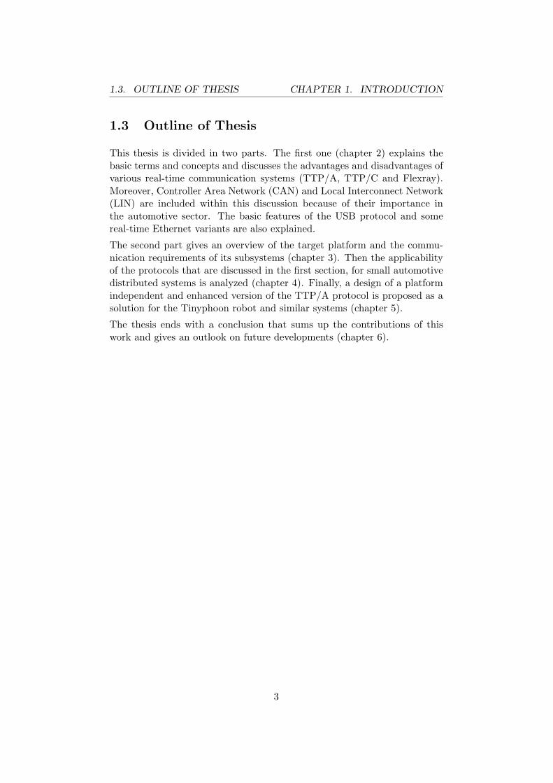
A node is an entity with a processor that runs an application. The appli-cation uses a communication protocol either in form of a software layer orin form of a piece of hardware. The bus transceiver converts logical signalsin according voltage levels. In figure 2.1 the general structure of a node isshown. The bus is the medium (e. g., a kind of wire or fiber), which all nodesare connected to. The whole network, including the nodes an the bus, iscalled cluster. The data packet that is transported through the network iscalled frame. Message can be used as synonym for frame and is often usedon a higher abstraction level.
The manner how the nodes are connected to each other is called topol-ogy. Common network topologies for real-time communication are the bustopology, the star topology and combinations of these two topologies. Star
4
2.1. CONCEPTS CHAPTER 2. REAL-TIME PROTOCOLS
Figure 2.1: Structure of a Node
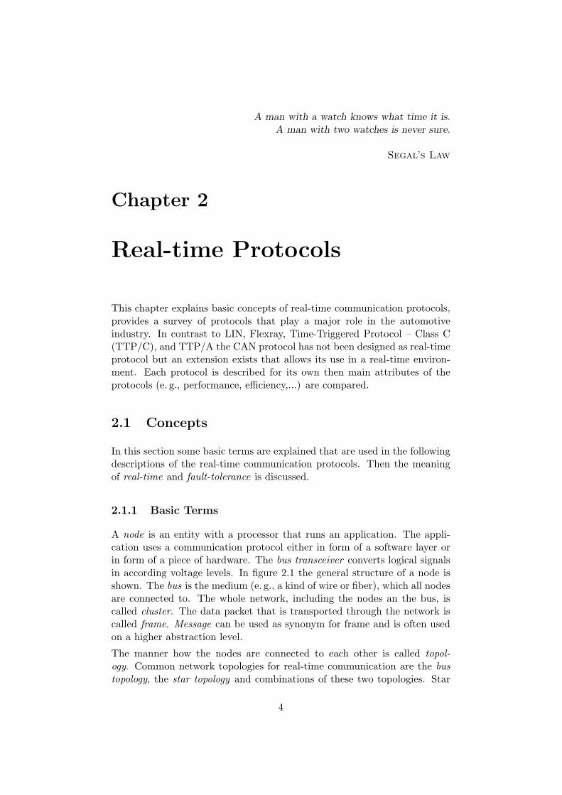
topologies can be passive (the branchings of the star are just connected at acentral point) or active (the branchings of the star are connected to a centralelectronic device). In normal networks there is only one bus. To ensure thatin case of a bus failure the communication can be continued, the bus can bereplicated. In figure 2.2 three examples for redundant topologies are shown.
(a) Redundant Bus (b) Redundant ActiveStar
(c) Redundant Mixed
Figure 2.2: Examples for Cluster Topologies
Babbling idiots are faulty nodes that transmit data on the bus constantlyand detain other nodes from sending. Bus guardians can be used to avoidthis if the communication schedule is defined a priori. The bus guardianscan be situated on the nodes (local bus guardians) or in a central devicelike a star coupler (central bus guardian). The bus guardians check on thebasis of the communication schedule, if a node is allowed to write on thebus at a given time and detain faulty nodes from monopolizing the bus.
If communication is triggered by the occurrence of a particular event, itis event-triggered (e. g., everytime the temperature of a room changes aframe is transmitted). In time-triggered communication networks only theprogression of time determines when a frame is sent (e. g., the temperatureof the room is transmitted every 30 seconds). The time-triggered approachhas two major advantages: The communication is predictable (e. g., oneframe every 30 seconds) and it supports a defined error detection latency
5

2.1. CONCEPTS CHAPTER 2. REAL-TIME PROTOCOLS
for omission failures (in our example a node is detected faulty, if no framehas been sent for 31 seconds). The major disadvantages of time-triggeredcommunication is that in many cases bandwidth is wasted, becauseredundant information is transmitted (e. g., five frames are sent with theinformation ”24C”, then with ”25C”; in an event-triggered system onlytwo frames are needed instead of six). Moreover, events can be missed isthe time-triggered communication is too slow (e. g., the room temperatureincreases from 24C to 26C within 30 seconds; the time-triggered systemonly sends two messages, the event-triggered three). However, it dependson the application whether this is a problem and whether it can be avoidedby increasing the update rate of the time-triggered system.
The efficiency of a communication protocol is the proportion of the du-rations of the transmission of the plain payload and of the complete dataframe. The efficiency strongly depends on the actual application. In thefollowing the best case efficiency of the protocols is calculated.
2.1.2 Real-Time
In a real-time systems the correctness of a result does not only depend onits value but also on the time[Kop97]. The error in the time domain can beas severe as an error in the value domain.
Every communication protocol delays the messages that it transports. Real-time protocols ensure that this delay is predictable and that the deadlinefor the arrival of the message is not missed. Moreover, by using a real-timeprotocol the jitter of that delay can be kept small. That means, that fromone communication round to another the delay is almost constant. This isimportant for the implementation of feedback control algorithms, which arein general unable to handle varying delays.
If the clocks of all nodes in a cluster are synchronized, a global time isestablished. In a cluster with a global time a time stamp refers to thesame moment in time on all nodes. The clocks of a cluster cannot besynchronized perfectly[Kop97]. The greatest difference between two clocksin a cluster is the precision of the cluster.
Three types of real-time systems can be distinguished based on the conse-quences when a deadline is missed[Kop97]:
Soft Real-Time In soft real-time systems the violation of a deadline causesonly a degradation of the service that is provided by the system (e. g.,voice-over-IP, video streaming, ...).
Firm Real-Time In a firm real-time system the violation of a deadline
6

2.2. CAN CHAPTER 2. REAL-TIME PROTOCOLS
prevents the system from working correctly but the malfunction hasno drastic consequences (e.g. small robots)
Hard Real-Time In hard real-time systems the violation of a deadlinecauses a catastrophe (e. g., fly-by-wire system, nuclear plant automa-tization, break-by-wire, ...).
2.1.3 Fault Tolerance
A fault-tolerant system continues being fully operational even if faults occur.The type and number of faults that have to be tolerated are specified in thefault hypothesis. Faults that are not covered by the fault hypothesis, couldcause a malfunction. To prevent the system from a steady malfunction anever-give-up strategy can be implemented. It tries to bring the systemback to an operational state even after an unexpected fault.
2.2 Controller Area Network
The first CAN specification was released by the Robert Bosch GmbH inthe year 1985. It describes the implementation of the first (physical) andthe second (data link) layer of the Open System Interconnect (OSI) model.Currently various implementations for the application layer of CAN com-munication systems exist (e.g. CANopen, SDS, DeviceNet and CAL) andCAN has become an International Organization for Standardization (ISO)standard. This standard with the number 11898 is divided in four parts: 1.data link layer and physical signalling, 2. high-speed medium access unit,3. low-speed, fault-tolerant, medium dependent interface, 4. time-triggeredcommunication.1
2.2.1 Mode of Operation
CAN nodes do not have addresses, but Instead every message has an identi-fier. The nodes of a cluster have to know, which messages they are interestedin and how to interpret them.
The medium access in a CAN cluster is controlled in a decentralized way.Data is encoded using a recessive and a dominant voltage level where adominant level always prevails a recessive one. Every node of the clusterlistens on the bus and verifies, that no other node is currently sending.Then the node starts the transmission of the message identifier field. Afterapplying the appropriate voltage level (recessive or dominant) according tothe bit being transmitted, the node checks the state of the bus. If it is equal
1available at www.iso.org
7

2.2. CAN CHAPTER 2. REAL-TIME PROTOCOLS
to the state aimed by the node the transmission of the bit is successful. Ifthe node tries to transmit a recessive symbol but the bus stays at a dominantlevel, another node is transmitting a dominant Symbol simultaneously. Thatis the other node has started transmitting a message with a higher priorityat the same time.
This technique of distributed arbitration is called Carrier Sense MultipleAccess/Collision Avoidance (CSMA/CA). If messages collide, the messagewith the identifier starting with the most dominant bits has the high-est priority and is transmitted successfully. The transmission of all othermessages is canceled. They are retransmitted as soon as the bus is idle again.
CAN defines four different types of frames. Remote frames are used torequest data from another node, which responds with the according dataframe with the same identifier. Data frames may also be sent spontaneously.Error and overflow frames are used to signal error conditions on the bus.
2.2.2 Additional Services
Beyond the normal data transportation CAN provides two additional ser-vices.
Acknowledgement
During the transmission of a frame a recessive bit is sent, the acknowledge-ment slot. This bit is overwritten with a dominant one by a receiver, if theframe has been received successfully. By checking the acknowledgement slota sender can notice if its transmission has been received successfully by atleast one node.
Error Signaling and Fault Confinement
All nodes perform tests to detect various errors (bit monitoring, bit stuff-ing check, frame check, acknowledgement and Cyclic Redundancy Check(CRC)). A detected error can be signaled to the other nodes by transmit-ting an error frame. Thus, all nodes of the clusters are informed aboutthe error and may discard the received message to keep the data consistentwithin the cluster. The transmitters will try to resend the message as soonas the bus is available again.
The reception of an error frame and the results of the own error detection areused to maintain two counters, one for receiving and one for transmittingerrors. The current value of these counters represents the quality of the
8
2.2. CAN CHAPTER 2. REAL-TIME PROTOCOLS
communication. Their values are increased in case of an error and decreasedwhenever communication is performed successfully.
Depending on these two values the CAN is one of the three states:
Error active The controller participates in the communication and sendserror frames when it detects an error.
Error passive The controller participates in the communication and sus-pends communication for the time of one error frame when it detectsan error.
Bus off The controller does not participate in the communication at all.
2.2.3 Packet Format
Four different frame formats are defined in the CAN specification:
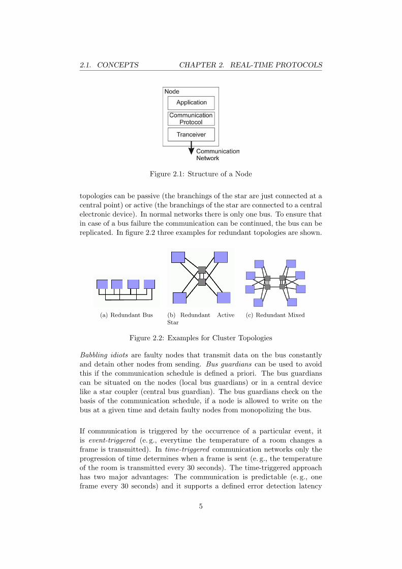
Data frame Data frames are used for sending application data from onenode to another. In figure 2.3 the structure of the CAN data frame isshown.
Figure 2.3: CAN Frame Format
SOF The start of frame field is a single dominant bit that marks thestart of the data or remote frame.
Identifier The identifier is used for classifying the type of the mes-sage. This field is also used for prioritizing the frames using theCSMA/CA technique.
RTR The Remote Transmission Request (RTR) bit is used to dis-tinguish data (RTS bit is dominant) and remote frames (RTRbit is recessive). This bit is also used for Carrier Sense MultipleAccess/Collision Detection (CSMA/CD).
r1 and r0 The bits r0 and r1 are reserved. They have to be trans-mitted as dominant bits but are ignored by the receiver.
9

2.2. CAN CHAPTER 2. REAL-TIME PROTOCOLS
Data Length Code The data length code stores the length of thepayload. It is encoded as standard binary number from zeroto eight. The first bit is the Most Significant Bit (MSB) anddominant bits represent a binary zero and recessive bits a binaryone.
Data The data field contains the payload and is transferred MSBfirst.
CRC The CRC code is 15 bits long and is generated from all fields de-scribed above using the generator polynomial shown in equation2.1.
x15 + x14 + x10 + x8 + x7 + x4 + x3 + 1 (2.1)
CRC Delimiter This single recessive bit delimits the CRC.
Acknowledge Slot This single recessive bit is overwritten by the re-ceiver, if a correct frame has been received.
Acknowledge Delimiter Another single recessive bit.
End of Frame The end of the frame is signaled by 7 recessive bits.
Remote frame This type of frames is used for polling other nodes. Thestructure of these frames is almost the same as the structure of thedata frames. But remote frames do not have a payload, the RemoteTransmission Request (RTR) bit is recessive and the data length codeis interpreted as the length of the requested data.
Error frame Error frames are used for signaling errors. It consists of sixto twelve dominant bits and eight recessive ones.
Overload frame These frames consist of six dominant and twelve recessiveones. They can only be distinguished from error frames because of thecontext they occur in.
Two data or remote frames are always divided by at least three recessivebits if no overload or error frame is transmitted.
Part B of the CAN specification introduces extended frames. These frameshave a 29 bit long identifier field. The additional 18 bits of the identifierare prefixed with the substitute remote request bit (SRR, recessive) and theidentifier extension bit (IDE, also recessive) and are filled in after the elevenidentifier bits of the standard frame.
In this way the SRR bit replaces the RTR bit of the standard frame and theIDE bit the reserved bit r1. Standard and extended frames are distinguishedby the IDE bit. Thus, both type of frames can be used within the samecluster.
10

2.2. CAN CHAPTER 2. REAL-TIME PROTOCOLS
2.2.4 Data Encoding
CAN uses the Non-Return to Zero (NRZ) encoding. A bit is signaled byapplying a dominant voltage level to the bus or releasing it for the completebit time.
On all fields of data or remote frames except the delimiters, the acknowledg-ment slot and the end of frame field bit stuffing is applied. Whenever fiveequal bits are transmitted consecutively a complementary bit is filled in.
Some error and overflows violate the bit stuffing rule and can thus be iden-tified as bit stuffing errors.
2.2.5 Physical Layer
Multiple standards describe a physical layer for CAN . The most importantones are:2
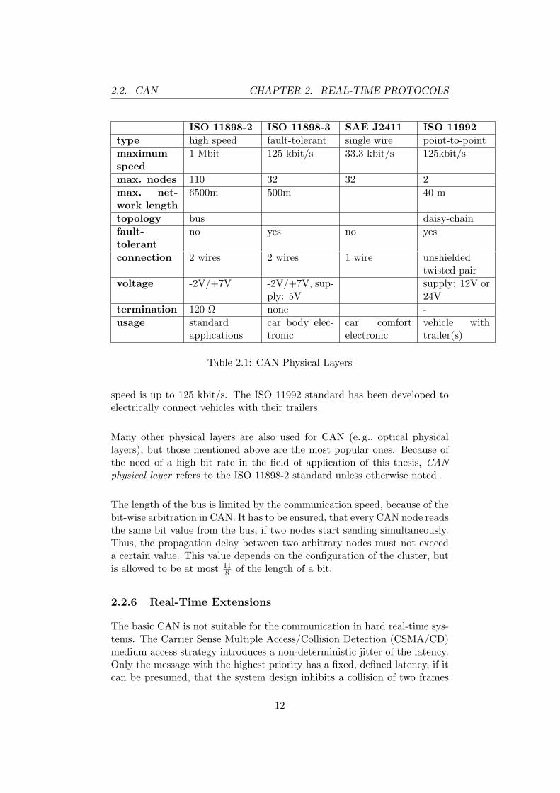
ISO 11898-2 high speed This physical layer specification provides acommunication speed of up to 1 Mbit and is the most common physicallayer for CAN networks. Signals are transmitted differentially on two wiresusing -2 V and +7 V. Only bus topology is allowed. Each end of the bushas to be terminated with a 120Ω resistor.
ISO 11898-3 fault-tolerant This specification targets applicationswhere fault tolerance is required. It needs no termination resistors andsupports various topologies. During normal operation differential commu-nication is used as in ISO 11898-2 at a speed of up to 125kbit/s. Butcommunication can be performed even using only one of the two wires ina degraded mode with reduced communication speed. This fact makes thisphysical layer fault-tolerant. The ISO 11898-3 specification is mainly usedin the automotive industry for car body electronics.
SAE J2411 single wire This specification has been designed for thecontrol of comfort electronics in cars. Short single wire networks of almostany topology can be created. A maximum of 32 nodes can communicatein this network with a speed of 33.3 kbit/s. A high speed diagnostic modeallows speeds up to 83.3 kbit/s.
ISO 11992 point-to-point In this specification a physical layer isdefined using daisy-chaining to connect the nodes. The networks must havea bus topology and must not exceed 40m of length. The communication
2http://www.can-cia.org/can/physical-layer/
11
2.2. CAN CHAPTER 2. REAL-TIME PROTOCOLS
ISO 11898-2 ISO 11898-3 SAE J2411 ISO 11992type high speed fault-tolerant single wire point-to-pointmaximumspeed
1 Mbit 125 kbit/s 33.3 kbit/s 125kbit/s
max. nodes 110 32 32 2max. net-work length
6500m 500m 40 m
topology bus daisy-chainfault-tolerant
no yes no yes
connection 2 wires 2 wires 1 wire unshieldedtwisted pair
voltage -2V/+7V -2V/+7V, sup-ply: 5V
supply: 12V or24V
termination 120 Ω none -usage standard
applicationscar body elec-tronic
car comfortelectronic
vehicle withtrailer(s)
Table 2.1: CAN Physical Layers
speed is up to 125 kbit/s. The ISO 11992 standard has been developed toelectrically connect vehicles with their trailers.
Many other physical layers are also used for CAN (e. g., optical physicallayers), but those mentioned above are the most popular ones. Because ofthe need of a high bit rate in the field of application of this thesis, CANphysical layer refers to the ISO 11898-2 standard unless otherwise noted.
The length of the bus is limited by the communication speed, because of thebit-wise arbitration in CAN. It has to be ensured, that every CAN node readsthe same bit value from the bus, if two nodes start sending simultaneously.Thus, the propagation delay between two arbitrary nodes must not exceeda certain value. This value depends on the configuration of the cluster, butis allowed to be at most 11
8 of the length of a bit.
2.2.6 Real-Time Extensions
The basic CAN is not suitable for the communication in hard real-time sys-tems. The Carrier Sense Multiple Access/Collision Detection (CSMA/CD)medium access strategy introduces a non-deterministic jitter of the latency.Only the message with the highest priority has a fixed, defined latency, if itcan be presumed, that the system design inhibits a collision of two frames
12
2.2. CAN CHAPTER 2. REAL-TIME PROTOCOLS
with the highest priority. The jitter of the latency is undetermined even formessages with the second highest priority, because the whole capacity ofthe bus may be used for messages with the highest priority and starvationof nodes that try to send messages with a smaller priority, might occur.
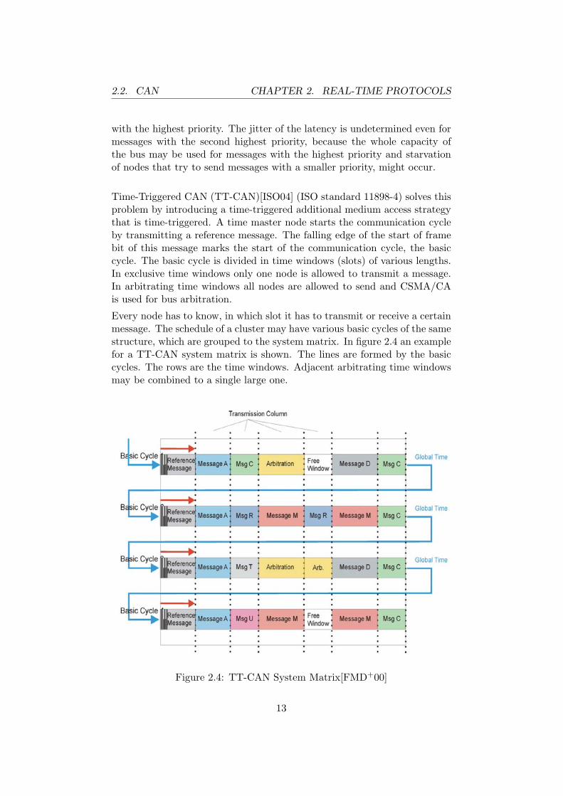
Time-Triggered CAN (TT-CAN)[ISO04] (ISO standard 11898-4) solves thisproblem by introducing a time-triggered additional medium access strategythat is time-triggered. A time master node starts the communication cycleby transmitting a reference message. The falling edge of the start of framebit of this message marks the start of the communication cycle, the basiccycle. The basic cycle is divided in time windows (slots) of various lengths.In exclusive time windows only one node is allowed to transmit a message.In arbitrating time windows all nodes are allowed to send and CSMA/CAis used for bus arbitration.
Every node has to know, in which slot it has to transmit or receive a certainmessage. The schedule of a cluster may have various basic cycles of the samestructure, which are grouped to the system matrix. In figure 2.4 an examplefor a TT-CAN system matrix is shown. The lines are formed by the basiccycles. The rows are the time windows. Adjacent arbitrating time windowsmay be combined to a single large one.
Figure 2.4: TT-CAN System Matrix[FMD+00]
13
2.2. CAN CHAPTER 2. REAL-TIME PROTOCOLS
Two levels of TT-CAN are defined. TT-CAN level one the time ismeasured in bit times of the CAN bus. Thus, the timeliness of the of thecommunication can be guaranteed, but no global time is established. Level2 of TT-CAN addresses this feature. The time master includes its currenttime in the reference message. The other nodes measure the time betweentwo reference messages and correct their clocks to match the values sent bythe master. The time in TT-CAN level 2 clusters is measured in NetworkTime Unit (NTU). The duration of a NTU is in the same order as theduration of one bit time. A global time with a precision of one NTU can beestablished.
The time master is obviously a single point of failure. Therefore, the timemaster can be replicated in a TT-CAN cluster. If no traffic is receiveda potential time master starts sending reference frames with a certainpriority. If it receives a reference frame with a lower priority, it transmitsa reference frame at the start of the next basic cycle. The other timemaster loses the arbitration because of the CSMA/CA algorithm. Thus,conflicts between potential time masters that start sending coinstan-taneously are resolved and the potential time master with the highestpriority succeeds. When an expected reference frame is not sent within acertain time-out, potential time masters start transmitting reference frames.
Though TT-CAN can be build in software using a CAN controller, thehardware of this controller at least has to be equipped with an additionalcircuitry for time-stamping incoming messages[HMFH00].
2.2.7 Efficiency
The maximum length of the payload of a CAN frame is eight bytes (= 64bits = Tpayload max). The overhead caused by wrapping the payload in aframe (Tframing) is calculated according to equation 2.7.
nheader = nsof + nid + nrtr + nreserved + nlengthcode = (2.2)= 1 + 11 + 1 + 2 + 4 = 19 (2.3)
ntrailer = ncrc + ncrcdel + nackslot + nackdel + neof = (2.4)= 15 + 1 + 1 + 1 + 7 = 25 (2.5)
Tframing = (nheader + ntrailer) · Tbit = (2.6)= (19 + 25) · Tbit = 44 · Tbit (2.7)
Another overhead (Tcoding) is added because bit stuffing is performed andthe bus has to be released for at least three bit times before a new frame is
14
2.2. CAN CHAPTER 2. REAL-TIME PROTOCOLS
started. The amount of bits that are stuffed in the frame depends on thecontent of the frame and the identifier. Thus, an upper and a lower boundare calculated for the coding overhead.
Tcoding max = nstuffbits max · Tbit + Tinterframe = (2.8)
=nheader + nmaxpayload + ncrc
5· Tbit + 3 · Tbit = (2.9)
= (19 + 64 + 15
5+ 3) · Tbit = (
985
+ 3) · Tbit = 22 · Tbit (2.10)
Tcoding min = (0 + 3) · Tbit = 3 · Tbit (2.11)
efficiencymax =Tpayload max
Tpayload max + Tframing + Tcoding min= (2.12)
=64 · Tbit
(64 + 44 + 3) · Tbit=
64 · Tbit
111 · Tbit= 0.5766 (2.13)
efficiency ′max =Tpayload max
Tpayload max + Tframing + Tcoding max= (2.14)
=64 · Tbit
(64 + 44 + 22) · Tbit=
64 · Tbit
130 · Tbit· Tbit = 0.4923 (2.15)
Depending on content and the identifier of the frames from zero to 19 bitsare stuffed in the frame. The maximum efficiency of CAN is 57.66% if no bitstuffing occurs. The TT-CAN protocol is less efficient because an additionaloverhead is caused by embedding the communication in time slots.
2.2.8 Availability
CAN controllers are available in many different versions: as IntellectualProperty (IP) (e.g. net list), as stand-alone controller or integrated in vari-ous microcontrollers.
Due to this variety and the low costs of these hardware implementations,software implementations of CAN are not common.
Manufactures of CAN enabled Integrated Circuits (IC) have to license CANfrom the Robert Bosch GmbH.
15

2.3. LIN CHAPTER 2. REAL-TIME PROTOCOLS
2.3 Local Interconnect Network
The Local Interconnect Network (LIN) is developed by the LIN consortium3.This protocol has been designed to satisfy the needs of the automotive indus-try for cheap and simple communication protocol for multiplexing varioussignals on a single bus. LIN can be used for real-time communication, butit does not offer a global-time or fault-tolerance features. The protocol canbe implemented in hardware and in software even on low performance off-the-shelf microcontrollers using a standard Universal Asynchronous Receiverand Transmitter (UART). This description of the LIN protocol is based onthe LIN specification 2.0 issued in 2003[LIN03].
2.3.1 Mode of Operation
LIN is a master-slave protocol. In every cluster a single master polls theslaves for a certain information according to its internal schedule. Thepolling process is implemented by splitting the LIN frame. The headeris sent by the master. It contains unique mark for the frame start and anidentifier that informs the nodes about the length and the meaning of thedata. The actual data is then sent in the response field by the slaves, whichis responsible for sending this type of messages. Every LIN master nodealso incorporates a client implementation, which is used for sending andreceiving data as well as for error detection.
Beyond 60 identifiers (0 – 59) for data frames special identifiers exist fordiagnostic frames (60 and 61) and user defined frames (62). The identifier63 is reserved for future use. The payload has a maximum length of eightbytes and is divided in signals. A signal is a value of a certain meaning anda certain length. LIN frames with the same identifier always contain thesame signals at the same position.
Each node has to be configured to read the frames, it is interested in, fromthe bus, and to respond to headers of frames it has to transmit. The com-plete schedule of the communication is only known by the master and isprocessed cyclically.
The LIN specification defines three modes a frame can be transmitted:
Unconditional frames These frames are standard way of transmittingframes. When the transmission of a certain frame is scheduled, themaster sends the header and the according node completes the framewith its data and a checksum.
Event-triggered frames To reduce the average bandwidth requirementsfor rarely changing signals, event-triggered frames have been intro-
3http://www.linlin-subbus.org
16

2.3. LIN CHAPTER 2. REAL-TIME PROTOCOLS
duced. Multiple nodes may react on the same identifier. The slavesonly respond on the header if they have something to transmit (e. g.,an event has occurred). If none of the slaves responds, the masterknows that no event happened. If one of the slaves replies, the frameis received correctly. However, another slave also may have started atransmission and stopped sending as it noticed the ongoing bus ac-tivity. Therefore, the master has to schedule another event triggeredframe to ensure that there are no other events pending. If more thanone slave responds on the header, the frame is corrupted, the masterdetects a checksum error and has to poll all slaves using unconditionalframes. The answers of the slaves contain the identifier of the re-lated unconditional frame. Thus, it can be distinguish, which eventoccurred.
Sporadic frames Sporadic frames can be scheduled by the master infree slots of the predefined, fixed communication schedule, wheneverneeded. Usually the slave implementation of the master node trans-mits the data of this frame.
2.3.2 Additional Services
Beyond the standard communication features, LIN offers means for diag-nostic communication and status management is able wake-up a sleepingcluster.
Diagnostic Communication
The LIN consortium has defined a special diagnostic transport layer. Di-agnostic communication is performed using special frames, master requestframes (identifier 60) and slave response frames (identifier 61).
The nodes of a LIN cluster have a node address for diagnostic communi-cation. Slaves can be addressed and messages up to 4095 bytes can beexchanged. The diagnostic transport layer fragments and defragments themessages accordingly, so they can be transported using the diagnostic framesthat carry at most eight bytes. Thus, the same diagnostic protocols can beused in the LIN cluster and on a higher level communication systems thatthe cluster might be connected to.
Status management
Every node has to report its state with at least one bit in one of the un-conditional frames, which it transmits. This bit is set, if an error occurredduring sending or receiving the response fields. The bit is cleared after its
17
2.3. LIN CHAPTER 2. REAL-TIME PROTOCOLS
transmission. The master processes these bits an deduces the state of thenodes.
But also the slave nodes use this information and the information aboutsuccessful data transfers to appraise their current status.
Cluster Wake-up
The master can put the cluster in sleep mode by sending a master requestframe with the invalid node address zero. Once the cluster is asleep everynode can wake it up by keeping the bus in the dominant state for 250µs to5ms. After the end of the wake-up signal all salves are ready for participat-ing in the communication within 100ms. The master starts executing itscommunication schedule not longer than 150ms after this signal.
2.3.3 Frame Format
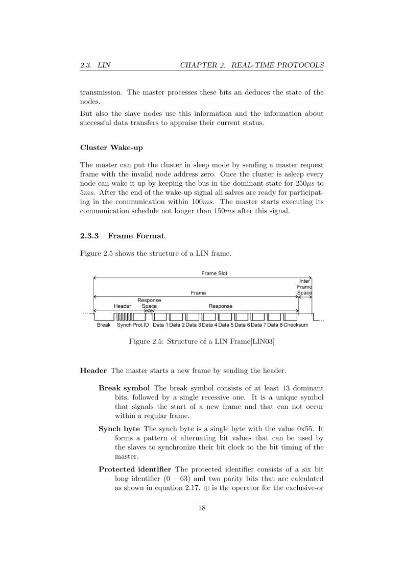
Figure 2.5 shows the structure of a LIN frame.
Figure 2.5: Structure of a LIN Frame[LIN03]
Header The master starts a new frame by sending the header.
Break symbol The break symbol consists of at least 13 dominantbits, followed by a single recessive one. It is a unique symbolthat signals the start of a new frame and that can not occurwithin a regular frame.
Synch byte The synch byte is a single byte with the value 0x55. Itforms a pattern of alternating bit values that can be used bythe slaves to synchronize their bit clock to the bit timing of themaster.
Protected identifier The protected identifier consists of a six bitlong identifier (0 – 63) and two parity bits that are calculatedas shown in equation 2.17. ⊕ is the operator for the exclusive-or
18

2.3. LIN CHAPTER 2. REAL-TIME PROTOCOLS
operation and ID [i] is the bit number i of the ID.
Bit6 = ID [0]⊕ ID [1]⊕ ID [2]⊕ ID [4] (2.16)Bit7 = ¬(ID [1]⊕ ID [3]⊕ ID [4]⊕ ID [5]) (2.17)
Response A slave responds to the header and completes the frame by trans-mitting the response field.
Data The data field contains at least one at most eight bytes of data.Signals with a length of more than one byte are transmitted inlittle-endian order.
Checksum In the LIN specification two types of checksums are de-fined. The classic checksum is calculated using the bytes of thedata field only. The calculation of the extended checksum alsoincludes the protected identifier. Both types of checksums arecalculated in the same way: All bytes are added in a eight bitregister. In case of an overflow, the carry bit is also added. Theinverted result of this calculation is then used as checksum.
2.3.4 Data Encoding
LIN uses standard UART frames with NRZ encoding. The frames have onestart, one stop bit and eight data bits that are sent Least Significant Bit(LSB) first.
There is only one exception. The break field consists of at least of 13 con-secutive dominant bits. This pattern is not a valid UART frame.
Every two bytes of a frame may be separated with an additional space. Thetotal length of the space must be smaller than 40% of the total frame length.
Two frames are separated by an inter frame space.
2.3.5 Physical Layer
LIN uses an improved version of the physical layer defined in the ISO stan-dard 91414. The bidirectional bus consists of a single wire and supports adata rate of up to 20 kbit/s. The LIN bus forms a wired AND gate. EveryLIN transmitter has a built-in pull-up resistor and can pull the bus down toground level with a transistor. The recessive state (≥0.6V) signals a logicalone and the dominant state (≤0.4V) signals a logical zero.
The maximum length of the LIN bus is 40 meters and up to 16 LIN nodesmay be connected.
4available at http://www.iso.org
19

2.3. LIN CHAPTER 2. REAL-TIME PROTOCOLS
2.3.6 Host Interface
The LIN specification defines a set of C-functions as interface to the hostapplication. This set includes functions for initialization, for manipulatingand querying the predefined signals, for managing the schedule in themaster node and for controlling the bus interface. A configuration and adiagnostic Application Programming Interface (API) are also available.
Beyond the programming interface the LIN specification specifies a file for-mats that store all communication-relevant settings, e. g., signals, framesand the master schedule (LIN description file) as well as a description ofLIN nodes (node capability file). These file formats ensure the correct col-laboration of development tools of various companies.
2.3.7 Efficiency
The maximum efficiency of a LIN frame can be calculated from the trans-ferred bytes of data and the minimal slot length that is needed to schedulethis message.
Theader is the amount of time for transmitting the header that has always thesame length. Tdata max is the time needed for transferring the payload data ofthe maximum length of eight bytes. Tresponse max includes Tdata max and thetime needed to transmit the checksum. Header and response transmissiontime are added to get the minimum time Tframe max for transmitting a LINframe with a payload of maximum length.
Theader = (Tbreak + Tsynch + Tid) · Tbit = (2.18)= (14 + 10 + 10) · Tbit = 34 · Tbit (2.19)
Tdata max = Ndata max · 10 · Tbit = (2.20)= 8 · 10 · Tbit = 80 · Tbit (2.21)
Tresponse max = Tdata max + Tcrc = (2.22)= 80 · Tbit + 10 · Tbit = 90 · Tbit (2.23)
Tframe max = (Theader + Tresponse max) · Tbit = (2.24)= (34 + 90) · Tbit = 124 · Tbit (2.25)
According to the LIN specification, the minimum length of a frame slot is40% longer than the minimum length of the packet that is sent in the slot.
Tframe slot = Tframe max · 1.4 = (2.26)= 124 · Tbit · 1.4 = 173.6 · Tbit (2.27)
20
2.4. FLEXRAY CHAPTER 2. REAL-TIME PROTOCOLS
The efficiency of LIN is calculated by opposing the minimum time for a frameslot (Tframe slot) and the time for sending the actual payload (Tdata max).
efficiencymax =Tdata max
Tframe slot= (2.28)
=80 · Tbit
173.6 · Tbit=
80173.6
= 0.4608 (2.29)
The upper bound for the efficiency of the LIN protocol is thus 46.08%.
2.3.8 Availability
LIN is often implemented in software, but there are also hardware imple-mentations and LIN IPs.
Only members may use intellectual properties of the LIN consortium. Tobecome an associated member an admission fee of $ 10,000.– and an annualfee has to be paid. Members do not have to pay any license fees for theirproducts that use LIN. The specification is openly available for downloadon the website of the consortium5.
2.4 Flexray
Flexray is an upcoming standard for real-time communication in the auto-motive industry. It is developed by the Flexray consortium6. This section isbased on the Flexray Protocol Specification[Fle05b] and the Flexray Physi-cal Layer Specification[Fle05a].
2.4.1 Mode of Operation
The Flexray protocol is executed in communication cycles. Each cycle con-sists of a static segment, a dynamic segment, a symbol window and a net-work idle time. The length of each segment is specified in macroticks. If nodynamic segment or the symbol is not used the length of the respective seg-ment can be set to zero. The static and dynamic segments are divided intotime slots. The clocks of all nodes are synchronized. Therefore, every nodeknows the number of the current slot and when a new slot starts. An actionpoint is defined by specifying the number of macroticks since the start of aslot. The transmitting node starts sending at the according action point.
5http://www.lin-subbus.org/frontend/stylesheets/request_doc.htm, visited on2006-10-06
6http://www.flexray.org
21

2.4. FLEXRAY CHAPTER 2. REAL-TIME PROTOCOLS
Every frame has an identifier that specifies the number of the slot, which ithas to be sent in. For every channel each identifier must not be used morethan once within one communication cycle.
Figure 2.6 shows the structure of a Flexray communication cycle.
Figure 2.6: Structure of a Flexray Communication Cycle[Fle05b]
There are three possibilities how communication in a Flexray cluster can beperformed:
1. The dynamic segment is not used. All communication is performedwithin the static segment.
2. Only one static slot is used for synchronization. The actual communi-cation is performed within the dynamic segment.
3. Both, the static and the dynamic segment are used for communication.
It depends on the requirements of the application, which of these modes ofoperation is adequate.
Static Segment
The static segment is used to exchange information with a guaranteed max-imum delay and jitter. Time Division Multiple Access (TDMA) is used forarbitration within the static segments. The segment is divided into timeslots with the same length that is equal for both channels.
The application can decide to send the same frame on both channels. Thus,faults on one channel can be tolerated. If fault tolerance is not needed thecommunication speed can be doubled for particular slots by sending differentframes on each channel.
22

2.4. FLEXRAY CHAPTER 2. REAL-TIME PROTOCOLS
Dynamic Segment
The dynamic segment is used to exchange information that has to be trans-mitted in varying and unknown intervals, efficiently. However, generally it isnot possible to determine a maximum delay for frames that are transmittedwithin the dynamic segment. Mini-slotting is used for the arbitration withinthis segment. The segment is divided into mini-slots. Dynamic slots are su-perimposed on them. If no data is transmitted in a dynamic slot, it onlyconsists of one single mini-slot. Otherwise the dynamic slot is expanded overas many mini-slots as needed for the transmission of the complete frame.The number of mini-slots depends on the length of the dynamic segment andmust not be exceeded. The smaller the identifier of a frame, the smaller isthe number of the slot a message is assigned to and the higher is the priorityof this message.
Symbol Window
In this segment symbols (such as the Media Access Test Symbol) may betransmitted. The protocol performs no arbitration for this segment. Thishas to be handled by the application.
Network Idle Time
No communication is allowed during the network idle time. The length ofthe idle time is the total length of the communication cycle minus the lengthof the static segment, of the dynamic segment and of the symbol window.
Addressing Modes
The nodes of a Flexray cluster do not have an address on the protocollayer. But all frames have an identifier that enables the receiving nodes tofilter incoming messages. Only those important for the application layer arestored.
Clock Synchronization
The right timing is crucial for the communication within a Flexray cluster.All nodes must agree on the number and the start of the current macrotick.This can only be guaranteed by performing a clock synchronization.
Within a Flexray cluster this is performed using the Fault-Tolerant MidpointAlgorithm[LL84]. Every node saves the arrival time of data frames that aretransmitted in the static segment and have a special bit set. These framesare called Sync Frames and are transmitted from nodes that have a reliable
23
2.4. FLEXRAY CHAPTER 2. REAL-TIME PROTOCOLS
clock that should be used for synchronization. Then the sender’s actionpoint (the point in time when the sender started transmitting the frame)is estimated by considering propagation delay. The difference between theestimated action point of the sending nodes and the action point of thereceiving node are stored in a sorted list. If a frame is transmitted an bothchannels, the smaller difference is stored in the list.
The k smallest and the k largest values are removed from the list, where kis calculated from the number of stored differences (n) using equation 2.30.
k =
0 if 1 ≤ n ≤ 21 if 3 ≤ n ≤ 72 if 8 ≤ n
(2.30)
The largest and the smallest of the remaining values are averaged to cal-culate the midpoint value. This value interpreted as the deviation of thenode’s clock from the global time. Offset and rate error are calculated fromthe deviation and corrected every second communication cycle during thenetwork idle time.
In a Flexray cluster with a communication speed of 10Mbit/s the clocks canbe synchronized with a precision better than 1µs.[Fle05b]
Node Integration
When a new node is connected to a cluster it has to adopt the currenttiming of the cluster to be able to join the communication. The processof integration differs for normal nodes and nodes that can initiate a clusterstart-up (coldstart nodes)
Normal nodes These listen on both Flexray channels and tries to receivetwo valid startup frames from a coldstart node, adopts its timing andperforms clock synchronization. Then it searches for startup framesfrom two distinct coldstart nodes and checks whether they fit in theown schedule. If this is the case for four cluster cycles and clocksynchronization can be performed without errors the node enters thenormal operation mode.
Coldstart nodes These perform a very similar procedure of integration,but they start normal operation after synchronizing themselves withat least one coldstart node for three cluster cycles.
Cluster Startup
If coldstart nodes do not receive any Flexray frames during the process ofintegration they initiate a cluster startup. The application may veto the
24

2.4. FLEXRAY CHAPTER 2. REAL-TIME PROTOCOLS
startup.
The startup is initiated by sending a Collision Avoidance Symbol (CAS).Then the coldstart node starts sending startup frames accordingly to itsschedule. If a startup frame is received between the transmission of the CASand the first transmission of the startup frame the node stops the startupand tries to integrate on the other coldstart node that transmitted thisframe. Thus, the scheduling of the startup frame decides, which coldstartnode performs the startup if more then one node initiated the cluster startupsimultaneously by sending the CAS.
Fault Handling
A fatal error within the protocol engine or the product specific part causesthe Flexray node to stop participating in the communication immediately.This stop can also be encompassed by the application through the ControllerHost Interface (CHI) .
Non fatal errors may cause the protocol engine to only degrade the commu-nication service that means it receives data frames from the bus but doesnot transmit any. However, the exact behavior in such cases depends on theconfiguration.
2.4.2 Additional Services
Beyond the basic data transportation features Flexray provides followingadditional services.
Fault Tolerance
Flexray supports the implementation of a fault-tolerant communication.The dual-channel topology provides means to implement communicationsystems that can tolerate the breakdown of one channel. But Flexray doesnot provide a complete ready-to-use solution.
Also the clock synchronization algorithm, the node integration and clusterstart-up process of Flexray are designed to tolerate faults. However, a faulthypothesis is not part of the Flexray specification.
In an additional specification bus guardians for Flexray controller are de-scribed. These guardians are are used locally, directly on the Flexray node.The bus guardians protect only the static segment against timing violations.
25

2.4. FLEXRAY CHAPTER 2. REAL-TIME PROTOCOLS
Global Time
To synchronize the medium access of the nodes within the TDMA schemethe clocks of the communication controllers have to be synchronized as de-scribed earlier. All communication controller of a Flexray cluster agree witha limited deviation on this time. It is made available to the host applicationand can be used for performing actions synchronously to the communicationor for time-stamping.
Membership
Flexray supports the implementation of a membership service but does notprovide a ready-to-use solution.
The frame format defines a flag that specifies whether a membership vec-tor is included within the payload or not. During a communication cycleFlexray controllers process the vector from all valid incoming frames fromboth channels and perform an or-operation. The result can be used by theapplication for implementing a membership service. It is the responsibil-ity of the application software to calculate and to transmit an appropriatenetwork management vector.
Cluster Wake-Up
To save energy a cluster can be set to sleep mode. Every node of the clustercan wake it up by sending the wake-up symbol. The transmission of thissymbol is triggered by the host application. The bus drivers of the othernodes detect the wake-up symbol and wake the communication controllerthat inform the host processor. The wake-up is only sent on one of the twochannels to ensure that communication is still possible, in case a faulty nodesends wake-up symbols continuously.
2.4.3 Frame Format
The Flexray frame format is shown in figure 2.7.
Figure 2.7: Flexray Frame Format
26

2.4. FLEXRAY CHAPTER 2. REAL-TIME PROTOCOLS
Header segment This segment contains important information about theframe.
Bits These bits are used to mark special frames.
Reserved Bit This bit is reserved for future use, must be trans-mitted as 0 and must be ignored when it is received.
Payload Preamble Bit This bit indicates that additional in-formation is stored at the beginning of the payload segment.
Null Frame Indicator If this bit is set the data in the payloadsegment is invalid.
Sync Frame Indicator If this bit is set, the node should usethe timing of this frame for its synchronization process.
Startup Frame Indicator This bit indicates whether theframe is a startup frame or not. Frames having this bit setare used for cluster startup and also have to be sync frames.
Frame ID The frame identifier specifies the slot, which the frame hasto be transmitted in. Therefore, every identifier may only be usedonce per communication round and per channel. 0 is an invalidframe identifier.
Length The length of the payload segment in words (two bytes).
Header CRC Some parts of the data in the header (sync and startupframe indicator, frame identifier and payload length) is relevantfor the right operation of the protocol. Hence, it is protected withthis additional header CRC. The CRC code is 11 bits long and isgenerated using the polynomial shown in equation 2.31.
x11+x9+x8+x7+x2+1 = (x+1)·(x5+x3+x1)·(x5+x4+x3+x+1)(2.31)
0x01A is used as initialization vector of the header CRC.
Cycle Count This field contains the the value of the communicationcycle counter of the sending node.
Payload segment In this segment the actual application data is transmit-ted. According to the value the state of the payload preamble bit in theheader segment additional administrative information might precedethe payload.
For frames transmitted within the static segment this information is anetwork management vector. With network management vectors thatare received during a communication cycle a bitwise OR operation isperformed and the result is made available to the application layer atthe end of the cycle. The length of the network management vectorhas to be configured in the communication controller. All additional
27

2.4. FLEXRAY CHAPTER 2. REAL-TIME PROTOCOLS
network management functionality has to be performed by the appli-cation software.
For frames within the dynamic segment the additional information is a16 bit long message identifier. This identifier may be used by receivingnodes for filtering certain packages. However, it is the task of theapplication to set the identifier and the payload preamble indicatorcorrectly.
The maximum length of the payload is limited by the number of bitsthat are used for encoding it. The seven bit long length field limitsthe maximum size of the payload to (27 − 1) · 2 = 127 · 2 = 254 Bytes.
Trailer segment The trailer segment contains a 24 bit CRC code. It is 11bits long and is generated using the polynomial shown in equation 2.32.
x24+x22+x20+x19+x18+x16+x14+x13+x11+x10+x8+x7+x6+x3+x+1 =
= (x+1)2·(x11+x9+x8+x7+x5+x3+x2+x+1)·(x11+x9+x8+x7+x6+x3+1)(2.32)
0xFEDCBA is used as initialization vector for frames sent throughchannel A and 0xABCDEF for those on channel B.
2.4.4 Data Encoding
The bits of the Flexray data frames are transmitted using the NRZ encoding.Before and after the actual frame data and between every two transmittedbytes special bit sequences are inserted to support synchronization betweensender and receiver.
Transmission Start Sequence Each transmission is started by pullingthe data line low for a predefined amount of time. This period is usedfor setting up active star coupler accordingly.
Frame Start Sequence Each data frame is preceded with one high bit.
Byte Start Sequence Each data byte is preceded with one high and onelow bit.
Frame End Sequence One low bit and one high bit are appended to eachframe.
Dynamic Trailing Sequence After the transmission of the last bit of aframe within the dynamic segment, the data line is hold low until thenext minislot. Then, a single high bit is transmitted.
Three different bit sequences may be transmitted as symbols:
28

2.4. FLEXRAY CHAPTER 2. REAL-TIME PROTOCOLS
poi
nt-
to-p
oint
pas
sive
bus
pas
sive
star
acti
vest
ar
maximum distance between two nodes 24m 24m 24m 24m to/from starminimum number of stubs 0 4 3 2maximum number of stubs 0 22 22 -minimum number of splices 0 2 1 -maximum number of splices 0 - 1 -
Table 2.2: Flexray Physical Layer Characteristics
Collision Avoidance Symbol This symbol is transmitted by pulling thedata line low for a certain amount of time. It is preceded by a trans-mission start sequence. The symbol is used during the cold start todetermine the leading cold start node. All other nodes integrate onthis node and synchronize their communication on it.
Media Access Test Symbol This symbol looks like the collision avoid-ance symbol. However, they can be distinguished because the mediaaccess test symbol is sent within the symbol window. The transmissionof this symbol is triggered via the CHI .
Wakeup Symbol This symbol consists of alternating sequences of low andhigh bits. The sequences have a predefined length. The number ofsignal changes also can be configured. The symbol is used to wake upthe sleeping nodes of a cluster. It may only be transmitted on onechannel at a time. Its transmission is triggered by the host.
2.4.5 Physical Layer
A passive bus, a passive star, or an active star topology can be used in aFlexray cluster. It is also possible to use a combination of the active starand the bus topology. The nodes of a Flexray cluster can be interconnectedwith one or two busses. If two busses are used, both have to belong to onesingle cluster. Bridges between different clusters can only be built using asecond communication controller.
A dedicated electrical physical layer specification for Flexray systems exists[Fle05a]. It defines a differential transmission using ± 600mV.
The maximum distance between two active stars is limited to 24m. Onlytwo active stars are allowed to be placed on every signal path.
29
2.4. FLEXRAY CHAPTER 2. REAL-TIME PROTOCOLS
The information is sent over the network using the NRZ coding and a max-imum speed of 10 Mbit/s.
2.4.6 Host Interface
The Flexray host interface is divided in two parts, the protocol data inter-face and the message data interface. The protocol data interface allows toconfigure the protocol parameters, to control the protocol execution (e. g.,change the execution state, perform external clock synchronization), andto read the status of the protocol execution (e. g., slot counter, macro tickcounter, clock rate correction).
Through the message data interface the received data can be accessed andthe data that has to be transmitted, is be handed over to the communica-tion controller. This interface is also used for configuring the handling ofincoming and outgoing data (e. g., in which time slot data is stored in whichbuffer).
Beyond, the host interface offers additional services: Received messages canbe filtered using the first two bytes of their payload. A powerful, con-figurable interrupt logic can provide interrupts on all important protocolevents. Moreover, the network management service preprocesses all incom-ing network management vectors (all vectors of a communication cycle areor-ed and the result is made available to the application).
2.4.7 Efficiency
For the calculation of the efficiency, only the static segment is considered.The maximum length of the payload of a Flexray frame is 240 bytes (= 1920bits = npayload max). The overhead caused by wrapping the payload in aframe (Tframeing) is calculated according to equation 2.34.
Tframing = (nheader + ntrailer) · Tbit = (2.33)= (5 · 8 + 3 · 8) · Tbit = 64 · Tbit (2.34)
Another overhead (Tcoding) is added because additional bits have to be trans-mitted at the start of a transmission, of a frame, and of a byte, as well asat the end of each frame.
Tcoding = (ntransmission start + nframe start + nbyte start · nbytes max + nframe end) · Tbit =(2.35)
= (3 + 1 + 2 · 240 + 2) · Tbit = 486 · Tbit (2.36)
30
2.5. TTP/C CHAPTER 2. REAL-TIME PROTOCOLS
efficiencymax =Tmaxpayload
Tmaxpayload + Tframeoverhead + Tcoding= (2.37)
=1920 · Tbit
(1920 + 64 + 486) · Tbit= 0.7773 (2.38)
According to equation 2.38 the maximum efficiency of the Flexray frameencoding is 77.73%. However, this calculation does not consider the paddingtime of the frames in the time slots. This time depends on the topology of thecluster. A lower bound for the maximum efficiency can be calculated fromthe maximum slot duration (Tslot max). According to [Fle05b] tslot max = 659Macroticks. At 10Mbit/s a Macrotick has a length of at least 1µs. ThusTslot max = 659µs.
efficiencymax lo =Tmaxpayload
Tslot max= (2.39)
=1920 · Tbit
659µs=
1920 · 10−7s
6590 · 10−6s= 0.2914 (2.40)
The lower bound for the maximum efficiency is 29.14%.
2.4.8 Availability
At the day of writing several Flexray implementations are available. TheRobert Bosch GmbH7 offers a Flexray intellectual property (IP) module thatis called E-Ray and that can be synthesized either as a stand-alone deviceor as part of another IC.
Freescale Semiconductors8 produces stand alone Flexray controllers calledMFR4200 and MFR4300.
Currently no software implementations of the Flexray protocol are known.
The development of Flexray is managed by the Flexray consortium. Aregistered copy of the Flexray specification is available for free, but the useof the intellectual property is only allowed to members. Memberships areavailable for EUR 7.500,- and for EUR 15.000,-.9
2.5 TTP/C
The TTP/C is a part of the Time-Triggered Architecture (TTA) and themajor member of the time triggered protocol family. It is developed by the
7www.bosch.com8www.freescale.com9according to the information on the Flexray website at 2006-08-26
31

2.5. TTP/C CHAPTER 2. REAL-TIME PROTOCOLS
TTA-Group10 and is mainly used in the avionic industry. Class C refersto the group of applications that TTP/C is designed for, as defined by theSociety of Automobile Engineers (SAE)11. Class C communication protocolsprovide high speed communication at minimum 125kbit/s that can be usedfor real-time control (e.g. engine control, brake by wire).
This chapter is based on the specification of the version 1.1 of the TTP/C[TTA03].
2.5.1 Mode of Operation
TTP/C uses a TDMA scheme to access the bus after a successful startuphas been accomplished. In a TDMA round every node may access the busonly once. At a configured time it is allowed to transmit data for a pre-defined time (node slot). Thus, all nodes in the cluster have to agree onthe actual time. This is achieved by synchronizing the clocks of the nodesas described later in this section. A appropriate configuration for the com-munication has to be created for every node. It is stored in the MessageDescriptor List (MEDL), a data structure in the Communication NetworkInterface (CNI), the application interface of the communication controller.The communication has to be designed in a way that at no time more thanone node is allowed to transmit data on the bus.
The TTP/C communication controller decides according to the MEDL whendata has to be transmitted on or received from the bus, and where in theCNI the data is read from and stored to, respectively. The application cannot influence the timing of the communication. The CNI forms a temporalfirewall[Kop97].
TDMA rounds with the same sequence of slots are grouped forming a clustercycle. Nodes with the same position within different TDMA rounds of thesame cluster cycle are equal in length and have the same sending node. Thecluster cycle is repeated continuously. Every node sends the same piece ofdata (same length and same semantic meaning) in its slot within a particulartype of TDMA round. The content of a frame may differ from one TDMAround to another. Figure 2.8 shows the structure of a cluster cycle.
Cluster Mode
Distributed systems may have more than one functional behavior, which arecalled modes. Depending on the current task of the system the mode canbe changed accordingly. Each mode of the distributed systems requires theexchange of a different set of data. TTP/C reflects these needs by allowing
10http://www.ttagroup.org11www.sae.org
32

2.5. TTP/C CHAPTER 2. REAL-TIME PROTOCOLS
Figure 2.8: TTP/C Cluster Cycle[TTA03]
the definition of multiple cluster cycles and offering means for switchingbetween them safely.
At least two cluster modes have to exist in every TTP/C cluster: the startupmode and one application mode. If it is required by the application addi-tional application modes can be added. Special modes may also be designedfor debugging, diagnosis or maintenance.
Virtual member nodes
In TTP/C a fixed slot in every TDMA round is allocated for every node.However, in a TTP/C cluster physical nodes may share a single node slot.The transmission of the data is multiplexed. The physical nodes access thebus alternately. They behave like a single node that is called virtual membernode.
Controller State
The controller state (C-state) is composed of a set of values that reflect theactual state of the communication controller:
Global Time The time of the start of the current slot in macroticks.
Round Slot Position The number of the current slot in the cluster cycle.
Cluster Mode The current cluster mode (defines, which schedule is used).
Deferred Pending Mode Changes Pending mode changes that will beperformed at the start of a new cluster cycle.
Membership Information Information about the activity of the nodesin the cluster. The membership information is consistent among allcluster nodes.
33

2.5. TTP/C CHAPTER 2. REAL-TIME PROTOCOLS
Thus, the C-state must be equal on all nodes under normal operating con-ditions. Otherwise, one or more nodes would violate the timing when theyaccess the bus or they do not agree on the list of active nodes. TTP/Cprovides means to check the consistency of the C-state on all nodes and torecover from C-state errors (Never Give Up (NGU) strategy).
Clock Synchronization
TTP/C uses the Fault-Tolerant Average (FTA) algorithm [KO03] to syn-chronize the clocks of the nodes: Every node measures the time betweenthe expected and the real arrival time of a data frame. The propagationdelay is considered by subtracting a configurable amount of time from themeasurement. If the received data frame is sent by a node with a preciseclock (according to the MEDL of the receiving node), the measured timedifference is included in the calculation of the clock correction term. It isstored on a push-down stack with a depth of four entries. At a slot thatis configured in the MEDL, all nodes calculate the correction term. Thesmallest and the largest value are removed from the stack. The average ofthe two remaining values is then used as clock correction term.
The nodes correct their clocks by a configurable number of microticks every-time a definable number of macroticks has elapsed until the complete clockcorrection term has been applied.
TTP/C also supports the synchronization to an external clock. The hostapplication informs the TTP/C controller about an external clock correctionterm, that is added to the internal one.
At minimum four nodes are needed to be able to tolerate one byzantine faultper TDMA round[KHK+96]. A dependable clock synchronization is crucialfor the functioning of the TDMA bus accessing strategy.
According to [KHK+96] the achievable precision of the ensemble of clocksin a typical cluster with a communication speed of 10Mbit/s is better than0.25µs.
Node Integration
An integrating node has to adopt the current C-state of the cluster. It listensfor frames, which include the current C-state (frames with explicit C-state,see 2.5.3). Within two TDMA rounds at least one frame with an explicitC-state has to be transmitted in order to allow integration of nodes. If sucha frame is received, the node sets its own C-state accordingly and startsparticipating in the communication in a passive way: frames are receivedand handed to the host and clock synchronization is performed. After aconfigurable number of correct frames has been received and more correct
34
2.5. TTP/C CHAPTER 2. REAL-TIME PROTOCOLS
than incorrect frames have been received (clique avoidance, see 2.5.2) thenode starts sending in its assigned slot.
Cluster Startup
A node performs a cold start, if its configuration allows a cold start andthe node has not received any frames during the integration process for acertain time. The node sends cold start frames (see 2.5.3) on both channels.It then receives frames until the it reaches its own sending slot. If the nodehas received frames and the majority of them have the same C-state, thenode starts transmitting frames according to its schedule.
In case that the majority of nodes in the cluster have another C-state, or incase that no frame has been received the node starts the integration processagain. The number of cold start attempts that my be performed is limited,to detain cold starting nodes with an incoming link failure from continuouslyimpeding the communication on the bus.
Cold start integration enabled nodes integrate on cold start frames. Thisprocess is very similar to the normal node integration. The main differencesis that cold start frames may collide. If this collision is detected by allnodes, the integrity of the frame destroyed and the frame is ignored. Acritical situation may occur, if two nodes send a cold start frame at almostthe same time. Due to the propagation delay of the bus, these two framesmay be received by the other nodes in a different order on networks witha bus topology. In networks with star topology each of the replicated starcouplers may decide differently, which frame comes in first.
TTP/C solves this problem by introducing the big bang. Every integratingnode ignores the first cold start frame. The cold starting nodes receive noresponse and retries the cold start after a certain time. This retry time-out islarger than the maximum propagation delay of the bus and is unique withinthe cluster. Therefore, there is no collision during the second attempt of thecold start and all nodes integrate on the same cold start node.
2.5.2 Additional Services
Besides the normal data transfer TTP/C offers some additional services.These are described in this section.
Fault Tolerance
One of the main design goals of TTP/C is fault tolerance. An additionalspecification for a fault tolerant layer (FT-COM) on top of TTP/C exists.It has the same interface as the normal CNI. Under this interface the com-
35

2.5. TTP/C CHAPTER 2. REAL-TIME PROTOCOLS
plete implementation of the fault tolerant communication is hidden. There-fore, the FT-COM CNI is completely transparent for the host application.The fault tolerant layer uses the replicated communication channels of theTTP/C bus.
TTP/C specifies central bus guardians that are displaced from the commu-nication controllers and powered by their own supply. Thus, the likelinessof a failure of the node and the bus guardian at the same time is reducedbecause of the spacial distance.
Other services that are described in the next sections the membership ser-vice, the implicit acknowledgement and the clique avoidance improve theability of detecting and handling faults additionally.
Global Time
To synchronize the medium access of the nodes within the TDMA schemethe clocks of the communication controllers have to be synchronized as de-scribed earlier. All communication controller of a TTP/C cluster agree witha limited deviation on this time. It is made available to the host applicationand can be used for performing actions synchronously to the communicationor for time-stamping.
Membership
Every TTP/C communication controller implements a membership vector.Every bit in this vector represents a node of the cluster. If a valid frame isreceived from a certain node in its sending slot within the TDMA round,the according bit in the vector is set to one. Otherwise, the bit is set tozero. The membership vector is part of the C-state. Thus, all nodes of acluster have to agree on the current membership vector.
Implicit Acknowledgement
A TTP/C controller can detect outgoing link failures using the membershipinformation of its successors. If the membership information is includedexplicitly in the frame only the according bit has to be checked. Otherwise,the membership information is only part of the CRC calculation. In thiscase the receiving node calculates both possible CRCs and compares it tothe received one. There are three possible cases:
1. The received CRC and the first calculated checksum are equal: Thelast transmission has been successful.
36

2.5. TTP/C CHAPTER 2. REAL-TIME PROTOCOLS
2. The received CRC and the second calculated checksum are equal: Adisturbance during either the last transmission or during the receptionoccurred. The following frame has to be investigated to make a finaldecision about the acknowledgement.
3. The received CRC is and both calculated CRCs are unequal: Thetransmission of the successor has been disturbed. Further investigationis needed to make a final decision about the acknowledgement.
In case a further investigation is needed the frame sent by the successor ofthe successor is used similarly to the description above to make a decision.If again both checksums are unequal, the frame of the next successor is used,and so forth.
Clique Avoidance
All nodes of a TTP/C cluster have to agree on the cluster’s current C-state.The C-state is communicated either implicitly or explicitly whenever a nodetransmits a frame. Groups of nodes that agree on the same C-state arecalled cliques. It is crucial for the proper functioning of the communication,that the developing of such cliques is avoided.
To detect cliques every node counts agreed and disagreed frames:
Agreed Frames are received frames with implicit C-state that pass theCRC test, received frames with explicit C-state that pass the CRCtest and contain the same C-state as the receiving node and framesthat are transmitted.
Disagreed Frames are received frames with implicit C-state that do notpass the CRC test and received frames with explicit C-state that passthe CRC test but do not contain the same C-state as the receivingnode.
If the number of the disagreed frames is larger than that of the agreed ones,it is very likely, that there are at least two cliques and the node is not amember of the largest one. In such a case the node stops participating inthe communication immediately. Thus, the formation of cliques is avoided.
2.5.3 Frame Format
TTP/C uses three different types of frames:
Frames with explicit C-state This type of frame consist of a frame typeidentifier, a possible mode change request, the C-state of the sending
37

2.5. TTP/C CHAPTER 2. REAL-TIME PROTOCOLS
communication controller and a CRC. Included in this CRC but notwithin the data frame is the schedule identifier of the frame. Integrat-ing nodes can only synchronize themselves on frames with an explicitC-state.
Frames with implicit C-state These frames are very similar to those ofthe preceding type. However, they only include the C-state in thecalculation of the CRC but not in the actual data frame. This allowsthe C-state of a controller to be tested for consistency without trans-mitting it. The disadvantage of this technique is, that communicationfailures and differences in the C-state can not be distinguished. Inmany cases communication failures are transient failures that do notrequire any action from the node whereas an illegal C-state is a criticalerror that detains the node from participating in the communicationcorrectly.
Coldstart frames This is a special type of frames. It is only used duringthe startup of the cluster. These frames have no payload and nocomplete C-state. They only transport a part of C-state (the currentglobal time and the current round slot) that is necessary for a node tosynchronize itself during the cluster startup.
In figure 2.9 the structure of these three types of frames is shown.
In current implementations maximum frame length is limited to 240 bytes.In a frame with an implicit C-state thereof 3 bytes are used for the CRCand one byte for the header.[Kop01].
2.5.4 Data Encoding
The TTP/C specification does not define a certain bit encoding. Only thetiming of the transmission of the data frames within the TDMA slots isspecified in a more detailed way.
A TDMA slot starts with the transmission of a node (transmission phase -TP). After the transmission the receiving nodes process the received dataframe (post-receive phase - PRP). Before a node starts sending, it has toprepare the data frame (pre-send phase - PSP). This has accomplished be-fore a new slot starts, in order that the transmission starts exactly on thebeginning of the time slot. In the time between post-receive phase and pre-send phase the communication controller is idle. The bus is only accessedduring the transmission phase.
Figure 2.10 depicts the slot timing.
38
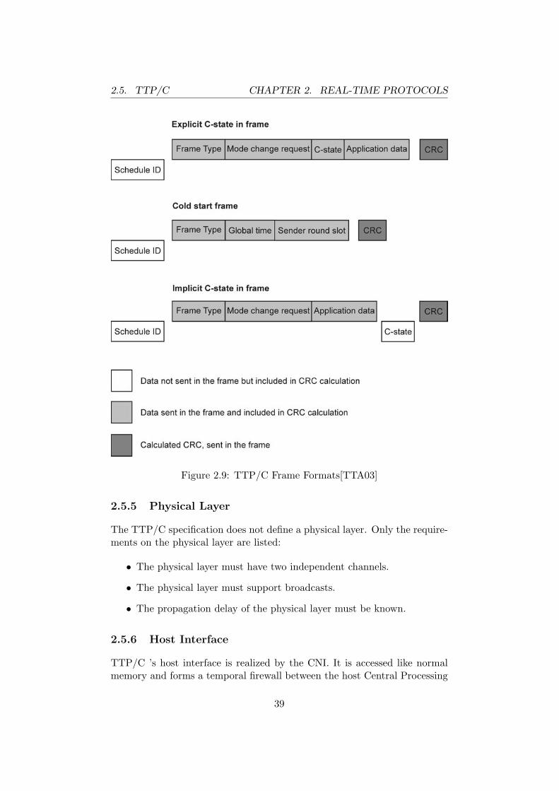
2.5. TTP/C CHAPTER 2. REAL-TIME PROTOCOLS
Figure 2.9: TTP/C Frame Formats[TTA03]
2.5.5 Physical Layer
The TTP/C specification does not define a physical layer. Only the require-ments on the physical layer are listed:
• The physical layer must have two independent channels.
• The physical layer must support broadcasts.
• The propagation delay of the physical layer must be known.
2.5.6 Host Interface
TTP/C ’s host interface is realized by the CNI. It is accessed like normalmemory and forms a temporal firewall between the host Central Processing
39
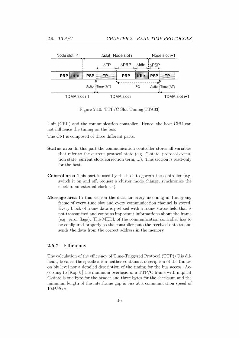
2.5. TTP/C CHAPTER 2. REAL-TIME PROTOCOLS
Figure 2.10: TTP/C Slot Timing[TTA03]
Unit (CPU) and the communication controller. Hence, the host CPU cannot influence the timing on the bus.
The CNI is composed of three different parts:
Status area In this part the communication controller stores all variablesthat refer to the current protocol state (e.g. C-state, protocol execu-tion state, current clock correction term, ...). This section is read-onlyfor the host.
Control area This part is used by the host to govern the controller (e.g.switch it on and off, request a cluster mode change, synchronize theclock to an external clock, ...)
Message area In this section the data for every incoming and outgoingframe of every time slot and every communication channel is stored.Every block of frame data is prefixed with a frame status field that isnot transmitted and contains important informations about the frame(e.g. error flags). The MEDL of the communication controller has tobe configured properly so the controller puts the received data to andsends the data from the correct address in the memory.
2.5.7 Efficiency
The calculation of the efficiency of Time-Triggered Protocol (TTP)/C is dif-ficult, because the specification neither contains a description of the frameson bit level nor a detailed description of the timing for the bus access. Ac-cording to [Kop01] the minimum overhead of a TTP/C frame with implicitC-state is one byte for the header and three bytes for the checksum and theminimum length of the interframe gap is 5µs at a communication speed of10Mbit/s.
40
2.6. TTP/A CHAPTER 2. REAL-TIME PROTOCOLS
Tpayload max = npayload max · 8 · Tbit = (2.41)= 236 · 8 · Tbit = 1888 · Tbit (2.42)
Tframing = nframing · 8 · Tbit (2.43)= 4 · 8 · Tbit = 32 · Tbit (2.44)
efficiencymax =Tpayload max
Tpayload max + Tframing + Tinterframe gap= (2.45)
=1888 · Tbit
1888 · Tbit + 32 · Tbit + 5µs= (2.46)
=1888 · 0.1µs
1920 · 0.1µs + 5µs=
188.8µs
197µs= 0.9584 (2.47)
The maximum efficiency that can be achieved in a TTP/C cluster is 95.8%.
2.5.8 Availability
TTP/C is available as IP from TTChip12 and as complete IC (e.g.AS8202NF from Austria Micro Systems13).
TTP/C has been designed to be implemented in silicon. Hence, there is nosoftware implementation available.
The development of TTP/C is managed by the TTA-Group14. A registeredcopy of the TTP/C specification is available for free. Chip designers andproducers have to pay a license fee for using the intellectual property.
The TTA-Group accepts associate members (companies that develop prod-ucts related to TTP/C ) and affiliate members (companies that want to useTTP/C related technology). Only the committee members have an influenceon the development of TTP/C .
2.6 TTP/A
TTP/A is a member of the time triggered protocol family for SAE class Aapplications. Class A covers low speed communication (about 10kbit/s) inthe domain of convenience features in vehicles. TTP/A has been designedto be implemented in software on small off-the-shelf microcontrollers and isused for sensor actuator bus systems. TTP/A is not fault tolerant and israrely used by the industry.
12http://www.ttchip.com13http://www.austriamicrosystems.com14http://www.ttagroup.com
41
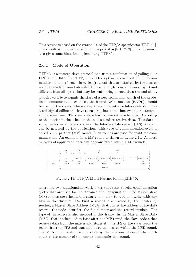
2.6. TTP/A CHAPTER 2. REAL-TIME PROTOCOLS
This section is based on the version 2.0 of the TTP/A specification[EEE+01].The specification is explained and interpreted in [EHK+02]. This documentalso gives some hints for implementing TTP/A.
2.6.1 Mode of Operation
TTP/A is a master slave protocol and uses a combination of polling (likeLIN) and TDMA (like TTP/C and Flexray) for bus arbitration. The com-munication is performed in cycles (rounds) that are started by the masternode. It sends a round identifier that is one byte long (fireworks byte) anddifferent from all bytes that may be sent during normal data transmissions.
The firework byte signals the start of a new round and, which of the prede-fined communication schedules, the Round Definition List (RODL), shouldbe used by the slaves. There are up to six different schedules available. Theyare designed offline and have to ensure, that at no time two nodes transmitat the same time. Thus, each slave has its own set of schedules. Accordingto the entries in the schedule the nodes send or receive data. This data isstored in a special data structure, the Interface File system (IFS) where itcan be accessed by the application. This type of communication cycle iscalled Multi partner (MP) round. Such rounds are used for real-time com-munication. An example for a MP round is shown in figure 2.11. At most62 bytes of application data can be transferred within a MP rounds.
Figure 2.11: TTP/A Multi Partner Round[EHK+02]
There are two additional firework bytes that start special communicationcycles that are used for maintenance and configuration. The Master slave(MS) rounds are scheduled regularly and allow to read and write arbitraryfiles in the cluster’s IFS. First a record is addressed by the master bysending a Master Slave Address (MSA) that carries the address of the datarecord: the node identifier, the file number and the record number. Thetype of the access is also encoded in this frame. In the Master Slave Data(MSD) that is scheduled at least after one MP round, the slave node eitherreceives data from the master and stores it in its IFS or the slave reads therecord from the IFS and transmits it to the master within the MSD round.The MSA round is also used for clock synchronization. It carries the epochcounter, the number of the current communication round.
42

2.6. TTP/A CHAPTER 2. REAL-TIME PROTOCOLS
As the description above shows, the proper reception of the fireworks byteis crucial for a slave to participate in the communication correctly. Thus,the fireworks bytes are protected by a code with a Hamming distance of atleast four[HH00]. The fireworks byte of the MSA round is 0x55. This bitpattern allows clock synchronization and an automatic baud rate detection.The lower three bits of the fireworks bytes specify the number of thecommunication schedule used for this round. Thus, there are eight differentrounds (0–7). Schedule number five (fireworks byte 0x55) is reserved forthe MSA round and number one is reserved for the MSD (fireworks byte0x49).
The execution of task can be triggered internally when a execution of a file isscheduled in the RODL or externally by the master, when the MSA containsan execution command. This feature is used to synchronize the actions of aTTP/A node to the communication.
2.6.2 Additional Services
Beyond the basic functionality for transferring data TTP/A offers additionalservices for synchronizing the cluster, for network management and for ac-cessing the data stored in the IFS of a cluster. The features membershipservice, cluster wake-up, and baptizing are optional and need not be part ofevery TTP/A implementation.
Global Time
TTP/A provides a simple clock synchronization that is not fault tolerant.The slaves synchronize their clocks on the start of the fireworks bytes thatare sent by the master. Additionally, the slaves adopt the epoch counter,which is included in every MSA round.
However, the protocol is designed to be implemented on very cheap hardwareand not every node is expected to have a precise crystal oscillator. Toguarantee that even in long MP rounds the clock precision of such nodesis good enough to be able to participate in the communication withoutviolating the timing constraints of the TDMA scheme, TTP/A slave nodescan be resynchronized on arbitrary bytes in this round. The time slots thatare used for synchronization are marked with a special flag in the scheduleof the slaves.
The clock synchronization has to be precise enough to ensure that the timedifference between the expected and the real start of a transmission neverexceeds the duration of one bit.
43

2.6. TTP/A CHAPTER 2. REAL-TIME PROTOCOLS
Membership Service
TTP/A provides a simple membership service that is not fault-tolerant. Themaster of the cluster maintains two membership vectors. In one a flag isset for every slave if it participates in the communication in MP rounds asexpected. The other vector provides information, if the slave nodes haveresponded in the last MSD round correctly after they had been addressedfor a read access in the previous MSA round.
Sleep mode
A cluster can be put in sleep mode by the master by sending a specialexecution command during the MSA round. The cluster wakes up again assoon as traffic is detected on the bus.
Baptizing
For configuration and debugging the slaves of a TTP/A cluster have tobe addressed in the MSA round. This address can be assigned staticallyat compile time or dynamically when the node is connected to the bus.A baptizing algorithm as proposed in [EHPS02] is used for the dynamicassignment. The problem is that all unbaptized that only all unbaptizednodes can addressed at once.
First the unique physical name of an unbaptized node has to be found:
1. The master write a physical name in a special record on all unbaptizednodes.
2. The master triggers a comparison of this physical name with the uniquename of the unbaptized nodes.
3. In the following MSD round only unbaptized nodes respond with aphysical name identifier that is greater than or equal the value writtenin step 1.
4. By repeating this algorithm a binary search is implemented.
Then the logical name has to be assigned:
1. The new logical name is written to a special record on all unbaptizednodes.
2. The master triggers the execution of a task that copies the logicalname to the intended location in the IFS if the physical name of thenode is equal to the comparison value.
44
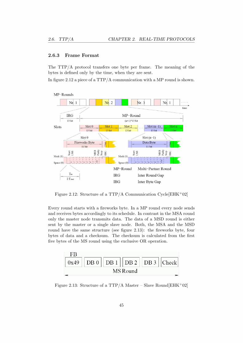
2.6. TTP/A CHAPTER 2. REAL-TIME PROTOCOLS
2.6.3 Frame Format
The TTP/A protocol transfers one byte per frame. The meaning of thebytes is defined only by the time, when they are sent.
In figure 2.12 a piece of a TTP/A communication with a MP round is shown.
Figure 2.12: Structure of a TTP/A Communication Cycle[EHK+02]
Every round starts with a fireworks byte. In a MP round every node sendsand receives bytes accordingly to its schedule. In contrast in the MSA roundonly the master node transmits data. The data of a MSD round is eithersent by the master or a single slave node. Both, the MSA and the MSDround have the same structure (see figure 2.13): the fireworks byte, fourbytes of data and a checksum. The checksum is calculated from the firstfive bytes of the MS round using the exclusive OR operation.
Figure 2.13: Structure of a TTP/A Master – Slave Round[EHK+02]
45

2.6. TTP/A CHAPTER 2. REAL-TIME PROTOCOLS
2.6.4 Data Encoding
TTP/A uses the NRZ encoding. The data is transmitted in standard UARTframes with a start bit, eight data bits, a parity bit, and a stop bit.
A bus idle time of one bit time before and after the UART frame is added.These idle times form a two bit Inter Byte Gap (IBG) when the frames aresent consecutively. Figure 2.14 shows a TTP/A byte frame.
Figure 2.14: Structure of a TTP/A Frame[EHK+02]
Two communication rounds are divided by a Inter Round Gap (IRG) of atleast 13 bit times. During this time the bus is idle.
2.6.5 Physical Layer
The definition of the physical layer is not within the scope of the TTP/Aspecification. The specification only defines the requirements on the physicallayer:
• The physical layer has to support the transportation of UART mes-sages.
• If the baptizing feature of TTP/A is used, the physical layer alsohas to support concurrent transmissions. A collision may destroy thetransmitted frames, but the master has to be able to detect that thereis ongoing communication on the bus.
The timing of the TTP/A protocol is defined on bit level. One node sendsafter the other and the gaps between two frames on the bus is fixed to 2 bittimes. Although this gap allows some jitter, this fact puts a restriction onthe length of the TTP/A bus.
46
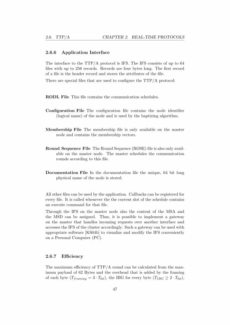
2.6. TTP/A CHAPTER 2. REAL-TIME PROTOCOLS
2.6.6 Application Interface
The interface to the TTP/A protocol is IFS. The IFS consists of up to 64files with up to 256 records. Records are four bytes long. The first recordof a file is the header record and stores the attributes of the file.
There are special files that are used to configure the TTP/A protocol:
RODL File This file contains the communication schedules.
Configuration File The configuration file contains the node identifier(logical name) of the node and is used by the baptizing algorithm.
Membership File The membership file is only available on the masternode and contains the membership vectors.
Round Sequence File The Round Sequence (ROSE) file is also only avail-able on the master node. The master schedules the communicationrounds according to this file.
Documentation File In the documentation file the unique, 64 bit longphysical name of the node is stored.
All other files can be used by the application. Callbacks can be registered forevery file. It is called whenever the the current slot of the schedule containsan execute command for that file.
Through the IFS on the master node also the content of the MSA andthe MSD can be assigned. Thus, it is possible to implement a gatewayon the master that handles incoming requests over another interface andaccesses the IFS of the cluster accordingly. Such a gateway can be used withappropriate software [KS04b] to visualize and modify the IFS convenientlyon a Personal Computer (PC).
2.6.7 Efficiency
The maximum efficiency of TTP/A round can be calculated from the max-imum payload of 62 Bytes and the overhead that is added by the framingof each byte (Tframing = 3 · Tbit), the IBG for every byte (TIBG ≥ 2 · Tbit),
47

2.7. OTHER PROTOCOLS CHAPTER 2. REAL-TIME PROTOCOLS
the IRG (TIRG ≥ 13 · Tbit), and the fireworks byte.
Tmax payload = Nmax payload · 8 · Tbit = (2.48)= 62 · 8 · Tbit = 496 · Tbit (2.49)
Tmax round = (Nmax payload + 1) · (8 · Tbit + Tframing + TIBG) + TIRG =(2.50)
= (63 · 13 + 13) · Tbit = 832 · Tbit (2.51)
efficiencymax =Tmax payload
Tmax round= (2.52)
=496 · Tbit
832 · Tbit= 0.5962 (2.53)
The upper bound for the efficiency of TTP/A is 59.62%.
2.6.8 Availability
The TTP/A protocol has been standardized in the Smart TransducerSpecification[OMG02] of the Object Modelling Group15. The specificationof the TTP/A protocol is available for free. Moreover, the source code of aC-implementation for the eight bit microcontrollers from Atmel16 is availableunder a modified version of the BSD license17.
Currently no pure hardware implementation of TTP/A exists, but an en-hanced UART supporting synchronization and time-stamping in hardwarehas been implemented[DEE03].
2.7 Other Real-Time Protocols
2.7.1 Real-time Ethernet
Ethernet is not suitable for real-time application because of its mediumaccess strategy. The CSMA/CD technique just detects collision and triesto retransmit the frame after a random time. Thus, CSMA/CD is notpredictable and frames may even get lost. However, due to the enormoussuccess of Ethernet within the last decade, Ethernet components havebecome very cheap. Meanwhile industrial Ethernet is even used in plantautomatization.
15http://www.omg.org16http://www.atmel.com17available at http://www.vmars.tuwien.ac.at/ttpa
48

2.7. OTHER PROTOCOLS CHAPTER 2. REAL-TIME PROTOCOLS
To make Ethernet suitable for real-time applications, the use of CSMA/CDhas to be avoided, that means that collisions have to be avoided. Mainly,there are three approaches for solving this problem:
Topology based Switched Ethernet avoids collision by establishing apoint-to-point connection between sender and receiver. Thus no colli-sions can occur. The problem of this solution is that switches createan additional, unpredictable delay.
Software based Examples for software based solutions are Powerlink andthe IEEE 1588 Precise Clock Synchronization Protocol. A low-leveldriver is used for synchronizing the clocks of the nodes and to establisha TDMA scheme on top of Ethernet to allow a collision free commu-nication. The precision that can be reached using these techniques iscoarse.
Hardware based Examples hardware based solution are PROFInet V3,EtherCAT and Time-Triggered Ethernet. PROFInet enforces aTDMA based access scheme through the hardware. EtherCAT uses akind of master-slave concept, where the frames from the master arepiped through one node after the other. The major problem of thesemethods is, that new, proprietary hardware is needed. Time-TriggeredEthernet also uses special switches but allows standard Ethernet con-trollers to participate in the communication that is not time critical.
A detailed discussion of these approaches can be found in [KS04a].
The components of real-time Ethernet are too large as they could be usedon small robots.
2.7.2 Universal Serial Bus
Another very wide spread protocol is the Universal Serial Bus (USB)protocol[USB00]. The USB protocol is a master-slave protocol. The hostcontroller, the master, polls data from the slaves. The USB specificationdefines various transfer modes that fit needs of different applications. Twoof them are interesting for real-time communication:
Isochronous Transfer For every connection with this transfer type a con-figurable bandwidth is assigned. In case of an error no retransmissionis scheduled.
Interrupt Transfer This transfer mode allows fast polling of the slave inregular intervals (up to one access every millisecond in high speedmode). In case of a transmission error the slave is polled once more.
49

2.8. COMPARISON CHAPTER 2. REAL-TIME PROTOCOLS
More and more microcontroller with included USB slave controllers arebrought on the market . There are also stand-alone ICs available. It ismuch more difficult to find USB host controllers. They are integrated inpowerful microprocessors or are designed as Peripheral Component Inter-connect (PCI) devices.
One of the major problems of using USB for real-time communication is,that the scheduling of the messages is performed by the driver of the hostcontroller. This task and the control of the USB host controller make thedriver complex. Moreover, important features like the clock synchronizationare missing.
2.8 Comparison
In table 2.3 the five protocols described above are compared.
The appearance of the specifications of Flexray and TTP/C shows the differ-ent design philosophies: Flexray is defined very precisely using Specificationand Description Language (SDL) diagrams, but leaves the implementationof many higher level services (e. g., the membership service) to the appli-cation designer. On the contrary the TTP/C specification defines a lot ofsophisticated features as part of the protocol, but does not give any detailedinformation for the implementation. A comparison of a previous version ofFlexray with TTP/C is presented in [Kop01].
Flexray allows event-triggered communication in the dynamic segment. Inthe static segment all time slots have the same length, but a node is allowedto send in various of these slots. TTP/C schedules slots with varying lengthswithin a TDMA cycle, but every node is allowed to transmit data at mostonce in a cycle.
Most of the algorithms used in the TTP/C protocol and some used in theFlexray protocol are verified formally. Another difference is that TTP/C alsosupports the use of central bus guardians. Flexray uses local bus guardians.
TTP/A provides real-time communication, but no fault tolerance. It is theonly protocol that is only available as software implementation. LIN canbe also used for real-time communication, but lacks the functionality of aglobal time. These two protocols are compared in detail in [EK04].
CAN is the only protocol that is not suitable for real-time communication.But a real-time communication capable protocol (TT-CAN) can be builtwith adapted hardware and an additional software layer.
50
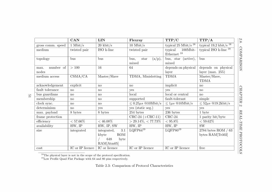
2.8.
CO
MPA
RIS
ON
CH
AP
TE
R2.
RE
AL-T
IME
PR
OT
OC
OLS
CAN LIN Flexray TTP/C TTP/Agross comm. speed 1 Mbit/s 20 kbit/s 10 Mbit/s typical 25 Mbit/s 18 typical 19,2 kbit/s 18
medium twisted pair ISO k-line twisted pair typical 100Mbit-Ethernet 18
typical ISO k-line 18
topology bus bus bus, star (a/p),mixed
bus, star (active),mixed
bus
max. number ofnodes
> 100 16 64 depends on physicallayer
depends on physicallayer (max. 255)
medium access CSMA/CA Master/Slave TDMA, Minislotting TDMA Master/Slave,TDMA
acknowledgement explicit no no implicit nofault tolerance no no yes yes nobus guardians no no local local or central nomembership no no supported fault-tolerant simpleclock sync. no no ≤ 0.25µs @10Mbit/s ≤ 1µs @10Mbit/s ≤ 52µs @19.2kbit/sdeterminism no yes yes (static seg.) yes yesmax. payload 8 bytes 8 bytes 254 bytes 236 bytes 1 byteframe protection CRC-24 (+CRC-11) CRC-24 1 parity bit/byteefficiency < 57.66% < 46.08% > 29.14%, < 77.73% < 95.8% < 59.62%availability HW, IP HW, IP, SW HW, IP HW, IP SWsize integrated integrated, 3.1
kbyte ROM/ 648 byteRAM[Atm05]
LQFP6419 LQFP8019 2784 bytes ROM / 63bytes RAM[Tro02]
cost IC or IP licence IC or licence IC or IP licence IC or IP licence free
18The physical layer is not in the scope of the protocol specification.19Low Profile Quad Flat Package with 64 and 80 pins respectively.
Table 2.3: Comparison of Protocol Characteristics
51

2.8. COMPARISON CHAPTER 2. REAL-TIME PROTOCOLS
Figure 2.15 shows a diagram that compares the most important attributesof the protocols. The attributes have been selected accordingly to the re-quirements that are put on a communication system when it is used on asmall autonomous system.
(a) CAN (b) LIN
(c) Flexray (d) TTP/C
(e) TTP/A
Figure 2.15: Comparison of the Protocols
Speed The comparison of the gross speed of the protocols shows thatFlexray and TTP/C are high speed protocols whereas LIN and TTP/A areused for low speed applications. CAN also allows high speed communication
52

2.8. COMPARISON CHAPTER 2. REAL-TIME PROTOCOLS
but far not as fast as Flexray and TTP/C. Because of the large differencesof the speed of the protocols a logarithmic scale has been used for speed inthe diagrams in figure 2.15.
Efficiency The most efficient protocol is TTP/C, which includes impor-tant protocol data only in the calculation of the CRC. Thus, the currentstate of the nodes can checked without transmitting any extra bytes. Theefficiency of CAN and TTP/A is comparable to the average efficiency ofFlexray. But in many application the efficiency of Flexray exceeds that ofCAN and TTP/A. The polling technique reduces the efficiency of LIN.
Max. Data Chunks The maximum length of data chunks that can betransmitted without fragmentation is limited to eight bytes in CAN andLIN. TTP/A solely uses frames with the length of a single byte. However,up to 62 bytes can be transmitted consecutively, because no additional pro-tocol information is stuffed in the frames. Flexray and TTP/C allow thetransmission of up to 254 and 236 bytes respectively in a single data frame.
Global Time CAN and LIN do not provide a global time for synchroniz-ing action in the cluster and for creating timestamps that are valid on allnodes of the cluster. The precision of the global time in a TTP/A cluster isnot as accurate as that of the global time in a Flexray or TTP/C cluster.The two latter protocols allow a clock synchronization with a precision bet-ter than one microsecond. Because of the large differences of the precisionof the global time in Flexray, TTP/C, and TTP/A clusters the logarithmof the reciprocal precision has been used for the diagram in figure 2.15.
Fault Tolerance Flexray and TTP/C are the only two communicationsystems that are fault-tolerant. They have replicated communication chan-nels, fault-tolerant start-up, and clock synchronization algorithms and busguardians. A specification of a transparent fault tolerance layer is availablefor TTP/C. The Flexray protocol leaves the design of such a layer to thedeveloper of the application.
Dependability Flexray and TTP/C have been designed to provide a highdependability. Especially the algorithms used by TTP/C have undergonenumerous tests and have been verified formally. CAN has been approved formany years and has be integrated in billions of products. TTP/A has notbeen thoroughly tested in everyday life, but its design addresses the issueof dependability. LIN is used for convenience functions in the automotiveindustry and dependability is not a main design criteria of LIN.
53

2.8. COMPARISON CHAPTER 2. REAL-TIME PROTOCOLS
Simplicity LIN is a very simple protocol. Especially a slave implementa-tion can be realized with very little effort. The implementation of TTP/Ais more sophisticated, but the effort is still in the same magnitude. Themedium access technique of CAN makes an implementation more elaborate.Flexray and TTP/C are far more complex than the three other protocols.
Cheapness The cost of using the protocols in an application is comparableto their simplicity. The simpler the protocol the cheaper is its use. However,apart from mass production this is not true for CAN. Because of the highnumber of applications that use this protocol, CAN controllers are verycommon and cheap.
Smallness LIN and TTP/A can be implemented in software occupyingsome hundred bytes of FLASH memory. CAN controllers are integrated onmany microcontrollers and no additional space on the Printed Circuit Board(PCB) is needed. In contrast, Flexray and TTP/C are only available as sep-arate communication controllers. Some implementations are even realizedin large Field Programmable Gate Arrays (FPGA).
54
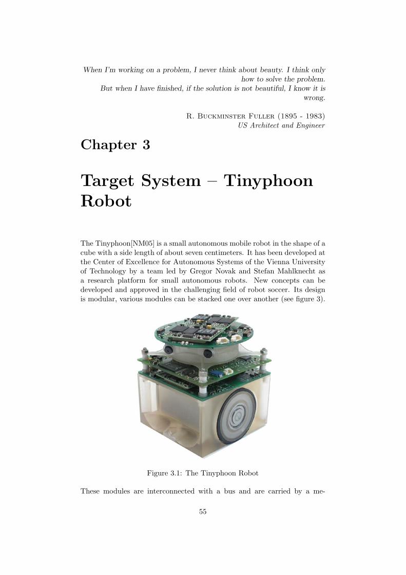
When I’m working on a problem, I never think about beauty. I think onlyhow to solve the problem.
But when I have finished, if the solution is not beautiful, I know it iswrong.
R. Buckminster Fuller (1895 - 1983)US Architect and Engineer
Chapter 3
Target System – TinyphoonRobot
The Tinyphoon[NM05] is a small autonomous mobile robot in the shape of acube with a side length of about seven centimeters. It has been developed atthe Center of Excellence for Autonomous Systems of the Vienna Universityof Technology by a team led by Gregor Novak and Stefan Mahlknecht asa research platform for small autonomous robots. New concepts can bedeveloped and approved in the challenging field of robot soccer. Its designis modular, various modules can be stacked one over another (see figure 3).
Figure 3.1: The Tinyphoon Robot
These modules are interconnected with a bus and are carried by a me-
55

CHAPTER 3. TINYPHOON
chanical system that has been designed for playing robot soccer. Thismechatronic part is about three centimeters high and is equipped with twostrong DC motors. Moreover, the rechargeable battery for powering theTinyphoon is stored here.
Three electronic modules have been designed up to now: a Vision Unit, aDecision Making Unit and a Motion Unit controlling the locomotion. Ad-ditional modules are planned to host extra sensors or provide computingpower. The current architecture of the Tinyphoon robot is shown in figure3.
Figure 3.2: System Architecture of the Tinyphoon Robot
56
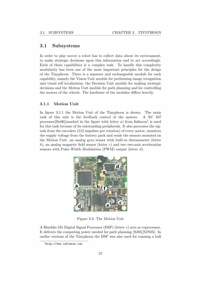
3.1. SUBSYSTEMS CHAPTER 3. TINYPHOON
3.1 Subsystems
In order to play soccer a robot has to collect data about its environment,to make strategic decisions upon this information and to act accordingly.Each of these capabilities is a complex task. To handle this complexitymodularity has been one of the most important principles for the designof the Tinyphoon. There is a separate and exchangeable module for eachcapability, namely the Vision Unit module for performing image recognitionand visual self localization, the Decision Unit module for making strategicdecisions and the Motion Unit module for path planning and for controllingthe motors of the wheels. The hardware of the modules differs heavily.
3.1.1 Motion Unit
In figure 3.1.1 the Motion Unit of the Tinyphoon is shown. The maintask of this unit is the feedback control of the motors. A XC 167processor[Sie06](marked in the figure with letter a) from Infineon1 is usedfor this task because of its outstanding peripherals. It also processes the sig-nals from the encoders (512 impulses per rotation) of every motor, monitorsthe supply voltage from the battery pack and reads the sensors mounted onthe Motion Unit: an analog gyro sensor with built-in thermometer (letterb), an analog magnetic field sensor (letter c) and two two-axis accelerationsensors with Pules Width Modulation (PWM) output (letter d).
Figure 3.3: The Motion Unit
A Blackfin 531 Digital Signal Processor (DSP) (letter e) acts as coprocessor.It delivers the computing power needed for path planning [SJ05][SJN05]. Inearlier versions of the Tinyphoon the DSP was also used for running a ball
1http://www.infineon.com
57

3.1. SUBSYSTEMS CHAPTER 3. TINYPHOON
detection algorithm[MON05]. It is connected with the XC 167 via a fastSPI connection.
Moreover, the Motion Unit is equipped with a radio module (letter f ) thatallows exchanging information with other Tinyphoon robots and receivingcommands from a personal computer.
The motor driver (letter g) controls the supply voltage of the motors ac-cordingly to the PWM signals from the XC 176.
The communication interface to other modules will be implemented on theXC 167, there is no dedicated communication controller.
XC 167CS The XC 167CS is a 16-bit automotive microcontroller with 5pipeline stages and runs at 40 Mhz. It has multiple register banks allowingfast context switches. It has several powerful peripherals that support akind of Direct Memory Access (DMA) mode. Some of the main features ofthe XC 167CS are listed below:
• 6 kbyteon-chip Static Random Access Memory (SRAM), 128 kbyteon-chip Flash Program Memory, 512 kbyteexternal Random Access Mem-ory (RAM)
• One cycle 16bit multiplication and one cycle Multiply and Accumulate(MAC) instruction
• 16 channel Analog Digital Converter (ADC) (10-bit or 8-bit, conver-sion Time down to 2.55µs)
• 16 programmable Interrupt priorities for 77 sources
• Five multifunctional timers/counters (with the functionality of a twochannel decoder)
• Two 16-channel capture/compare units and flexible PWM signal gen-eration
• Two synchronous/asynchronous serial communication channels (US-ART), two high-speed synchronous serial communication channels
• Dual CAN Interface
• I2C bus interface
Blackfin coprocessor The Blackfin processor is connected to the XC 167via a Serial Peripheral Interface (SPI) interface. It runs at 600 MHz andworks as coprocessor. The Blackfin processor from Analog Devices 2 is a
2www.analogdevices.com
58

3.1. SUBSYSTEMS CHAPTER 3. TINYPHOON
mixture of a microprocessor and a DSP. Therefore, it is perfectly suited fornumber crunching applications like path planning.
Sensors A gyro sensor detects the rotation of the robot and two orthog-onally mounted acceleration sensors sense the change of velocity in eachdirection. The magnetic field of the earth is also measured, but the re-sults of this sensor are disturbed because of the strong magnetic fields ofthe electro motors. 2 magnetic encoders on the wheels with 512 pulses perrotation
3.1.2 Vision Unit
The Vision Unit subsystem is shown in figure 3.1.2. The Vision Unit enablesthe robot to get an overview about its environment. Two CMOS cameraswith a resolution of 640 x 480 take pictures simultaneously. Each of them isconnected to a separate core of a dual-core Blackfin 561[Dev06] DSP fromAnalog Devices3 (marked with letter h). The two cores perform edge andcolor blob detection. The gathered data is then sent to a single-core Blackfin537 DSP (letter i) via SPI4, where the two-dimensional edges are combinedand three-dimensional lines are calculated. Based on the blobs and the linesobject recognition can be performed. More details about the vision systemcan be found [BAS+06].
Figure 3.4: The TinyVision subsystem
The complete subsystem is mounted on a head that can be rotated bya stepper motor. This motor is controlled by a LPC 2119 ARM7-TDMIprocessor[Phi06] (letter j ) that also functions as a communication interfaceto the other subsystems. It is connected to the single-core DSP via SPI.
3http://www.analog.com4Serial Peripheral Interface
59

3.2. COMMUNICATION CHAPTER 3. TINYPHOON
3.1.3 Decision Making Unit
An embedded 32-bit processor provides the necessary computation power fordecision making. A built-in floating point unit supports algorithms based onfuzzy logic or neuronal networks and various filter algorithms. Linux or Win-dows CE can be used as operating system on this platform. The processorsof the MCP family with Power architecture from Freescale5 are currentlyevaluated regarding its use on the Decision Making Unit. S fuzzy logicframework for the Decision Unit has already been implemented [Web06].
Two tasks are assigned to the Decision Making Unit:
1. It merges the data received from the sensors on the Motion Unit, fromthe vision unit and from other robots to create a world model.
2. Decisions are made based upon the interpretation of this world modeland a predefined strategy.
Integrating a communication system with high real-time requirements aspart of such a complex software system is only possible using special oper-ating systems (e.g. Real-Time Linux). Therefore, we decided to integrate aLPC 2119 ARM7-TDMI processor for handling the communication.
3.2 Communication Requirements
This section analyzes the data to be exchanged and additional attributes ofthe communication system.
3.2.1 Data Provided/Needed by the Subunits
Tables 3.1, 3.2, and 3.3 show the data that needs to be communicated byeach module with a description of the data, its length, the transmissiondirection (input or output) and the update interval.
Table 3.1 lists the data that is sent and received by the Vision Unit. TheVision Unit has to be configured with the description of the objects thathave to be recognized. The more different types of objects are to be searchedfor in the image the slower runs the detection algorithm. A maximum ofeight object descriptions can be processed at a time. But these descriptionscan be changed for every new image. A list of the recognized objects is thentransmitted by the Vision Unit. Moreover, the to-be and the current positionof the rotatable head and and the result of the visual self-localization has tobe communicated.
5http://www.freescale.com
60

3.2. COMMUNICATION CHAPTER 3. TINYPHOON
Description Len Dir Intervalobject descriptions 8 · 32 I 20msdetected objects 16 · 8 O 20msto-be head position 2 I 20mslast head position 2 O 20msself-localization 6 O 20ms
Table 3.1: Input/Output Data of the Vision Unit
The communication requirements of the Motion Unit are shown in table 3.2.It receives a command specifying the action to be performed with the nec-essary parameters. The Motion Unit provides the data collected from thesensors as well as commands and data from other robots that is received viathe wireless link.
Description Len Dir Intervalcommand 12 I 20msposition delta 6 O 20msgyro sensor 2 O 20msacceleration sensor 2*2*2 O 20msmagnetic field 2 O 20mstemperature sensor 1 O 1000mssupply voltage 1 O 1000msremote command 32 O 20msremote response 32 I 20msremote robot data 3*64 O 20ms
Table 3.2: Input/Output Data of the Motion Unit
The communication requirements of the Decision Unit are shown in table3.3. The results of the object recognition of the Vision Unit, data receivedvia the serial link and the information from the sensors on the Motion Unitare combined with the knowledge about the environment (e.g. the footballground, the soccer game) to a more reliable world model.
3.2.2 Real-Time Requirements
The main sensor of the Tinyphoon is the camera system. The maximumupdate frequency of the Vision Unit is 50 Hz. This frequency is also usedfor scheduling communication cycles. A trigger for the communication maybe received via the wireless link to synchronize the robots. This is important,
61

3.2. COMMUNICATION CHAPTER 3. TINYPHOON
Description Len Dir Intervalcurrent position 6 O 20msteammates 3 · 6 O 20msopponents 4 · 6 O 20msball 4 O 20msgoals 2 · 6 O 20msboards 4 · 6 O 20ms
Table 3.3: Input/Output Data of the Decision Unit
because information about recognized objects is exchanged among the robotsand this is much more useful if the robots rate exactly the same situation.
The maximum speed of the Tinyphoon robot is 4 m/s. Therefore, an objectmay move up to 2 · 8 cm from one image to another (e.g. two Tinyphoonrobots driving with full speed in opposite directions). State estimation canbe used to calculate the likely position of objects in the near future. However,this requires that the point in time when the picture is taken is knownexactly.
If an error of ≤ 1 mm is considered as negligible, the overall jitter (includingthe jitter of the communication) has to be smaller than 125 µs.
3.2.3 Fault Tolerance / Dependability Requirements
Every functional unit exists only once on the Tinyphoon. Therefore, there isno fault tolerance on level of functional units. This is not a serious problembecause a fail safe state exists, the robot can stop all motors at any time.
The communication system is partly integrated on functional units (e.g. theXC 167 microcontroller on the Motion Unit) and can not be replicated toprovide redundancy.
Moreover, all subsystems depend on each other. The Tinyphoon can notcontinue operation when a subsystem fails. However, the failure of a sub-system or of the communication system must be detectable for every otherunit to change to a safe state.
The length of the communication wires amounts only in a few centimetersand using the physical layer with differential signal transmission protects thedata on the bus against electromagnetic disturbance (e.g. from the motors).
The small size of the Tinyphoon robot guarantees that no human and nomachine could be harmed in case of a failure. Hence, features related tofault tolerance need not be considered when a communication protocol forthe Tinyphoon robot is selected.
62
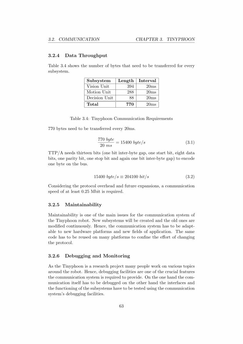
3.2. COMMUNICATION CHAPTER 3. TINYPHOON
3.2.4 Data Throughput
Table 3.4 shows the number of bytes that need to be transferred for everysubsystem.
Subsystem Length IntervalVision Unit 394 20msMotion Unit 288 20msDecision Unit 88 20msTotal 770 20ms
Table 3.4: Tinyphoon Communication Requirements
770 bytes need to be transferred every 20ms.
770 byte
20 ms= 15400 byte/s (3.1)
TTP/A needs thirteen bits (one bit inter-byte gap, one start bit, eight databits, one parity bit, one stop bit and again one bit inter-byte gap) to encodeone byte on the bus.
15400 byte/s ≡ 204100 bit/s (3.2)
Considering the protocol overhead and future expansions, a communicationspeed of at least 0.25 Mbit is required.
3.2.5 Maintainability
Maintainability is one of the main issues for the communication system ofthe Tinyphoon robot. New subsystems will be created and the old ones aremodified continuously. Hence, the communication system has to be adapt-able to new hardware platforms and new fields of application. The samecode has to be reused on many platforms to confine the effort of changingthe protocol.
3.2.6 Debugging and Monitoring
As the Tinyphoon is a research project many people work on various topicsaround the robot. Hence, debugging facilities are one of the crucial featuresthe communication system is required to provide. On the one hand the com-munication itself has to be debugged on the other hand the interfaces andthe functioning of the subsystems have to be tested using the communicationsystem’s debugging facilities.
63

3.2. COMMUNICATION CHAPTER 3. TINYPHOON
For software development a Joint Test Action Group (JTAG)interface[IEE90] exists for every microcontroller or processor. How-ever, JTAG debugging interfaces are not compatible for devices fromdifferent vendors. Thus, a mechanism is needed to access the interface ofevery subsystem.
In the future we also plan to simulate parts of the Tinyphoon in softwarefor testing purposes. Hence, a fast real-time communication between thesimulation host (typically a standard personal computer) and the respectiveTinyphoon hardware will be required.
3.2.7 Cost
The latest technologies are used to build the Tinyphoon, which is very cost-intensive. However, the cost for particular development tools turned out tobe much more expensive than the actual hardware. Therefore, the avail-ability of free or low priced development tools and documentation is vitallyimportant for future extensions.
3.2.8 Implementation Effort
Currently various platforms are used on the Tinyphoon. Therefore, thecommunication system has to be integrated on each of this platforms. Asmall implementation effort allows the fast adaption of the communicationsystem to new hardware platforms.
3.2.9 Comprehensibility of Interfaces
On large microcontrollers or processors a communication layer is introduced.So only a few developer get in touch with the interface of the communicationsystem directly. Application programmers can use an API to access thefunctionality of the communication system. As the Tinyphoon is a veryheterogeneous system a comprehensible interface makes it easier to portthis API to other platforms.
64

It requires a very unusual mindto undertake the analysis of the obvious.
Alfred North Whitehead (1861 - 1947)English Mathematician and Philosopher
Chapter 4
Problem Analysis
This section analyses existing implementation of the communication on theTinyphoon robot and discusses the suitability of the real-time protocolsdescribed in chapter 2 for the use on this autonomous system.
4.1 Current Communication
Currently, two modules for the Tinyphoon are available: the Motion Unitand the Vision Unit module. The two modules originally communicatedusing the CAN protocol. The communication was performed by theintegrated CAN controllers of the XC 167 on the Motion Unit and of theLPC 2119 on the Vision Unit. The LPC 2119 has been added to theschematics of the Vision Unit to perform the rotation of the head and allcommunication related tasks, whereas the XC 167 has to perform manyother, partly time critical tasks: reading the sensors and the encoders,generating the PWM signals for the motors, sending and receiving datathrough the wireless link and communicate with its co-processor.
The hardware of the modules has been designed in a way that allowsconnecting a CAN transceiver either to the I/O pins of the integratedCAN controller or to the I/O pins of the UART of the LPC 2119 and theXC 176, respectively. This guarantees flexibility and allows the softwareimplementation of a communication protocol. Thus, a communicationprotocol that can be implemented in software and that uses the serial portscan be integrated on the Tinyphoon without having to modify the hardware.
For the FIRA World Championship in Summer 2006 a stripped-down versionof the Tinyphoon has been created. It consists only of a motion and a visionunit. These two modules communicate with a very simple protocol, based on
65
4.2. FEATURES VS. COMPLEXITY CHAPTER 4. ANALYSIS
standard UART frames. There is no mechanism for bus arbitration requiredbecause the connection is bidirectional. However, the communication systemturned out to be one of the most error-prone subsystems. Problems withthe interpretation of the semantic and the structure could be solved byrendering the specification of the protocol more precisely. But the receptionof messages asynchronously to the program execution caused unexpectedproblems that were hard to track down and solutions were quite complex.Moreover, this approach is not applicable for systems with more than twocommunication partners.
4.2 Features Versus Complexity
Flexray and TTP/C offer by far the most features related to real-time andfault tolerance. The communication controllers have interfaces with sev-eral communication parameters that have to be configured extensively toestablish a communication. This can hardly be accomplished without usingspecial tools, like cluster designers. These tools are very expensive. Thefault-tolerant features of Flexray and TTP/C would lead to an unnecessaryoverhead since the intended application does not require fault-tolerance.Moreover, with a small number of nodes as on the Tinyphoon both com-munication systems only run in a degraded mode that is not really fault-tolerant.
CAN, LIN, and TTP/A provide less features but the configuration and theuse of the communication interfaces are much simpler. Anyway, TTP/Aeven provides a simple membership service and a global time that is requiredto synchronize tasks in different subsystems.
4.3 Hardware Versus Software Implementation
Small systems like the Tinyphoon put strong restrictions on the design of thePCB. An external communication controller needs additional space on thePCB. It may not be possible on all systems to provide this space. However,on the Vision Unit the LPC 2119 microcontroller is only used for the gen-eration of a PWM signal for rotating the head and for the communication.The PWM signal could also be generated on one of the Blackfin DSP. TheMF4300 Flexray controller has about the same size as the LPC 2119. Thus,the communication controller could be used instead of the microcontroller.
On the Motion Unit the XC 167 performs many tasks and can not bereplaced by a communication controller. Because of the high number ofsensors and the necessary analog circuitry there is not enough space foran additional communication controller without a complete redesign of the
66

4.4. RT COMMUNICATION IN SW CHAPTER 4. ANALYSIS
Motion Unit.
Software implementations of communication systems require additional cal-culation time and peripherals. On the LPC 2119 of the Vision Unit enoughresources are available. The XC 167 on the Motion Unit is also equippedwith enough peripherals and plenty of calculation time is available, becausecalculation intensive tasks are delegated to the coprocessor. However, theXC 167 already has to perform some time-critical tasks. These have to becombined with the requirements of the communication system. One possi-bility is that the scheduler of the communication also triggers all the othertime critical tasks.
4.4 Real-time Communication in Software
This section discusses the feasibility of the software implementation of time-triggered CAN, LIN and TTP/A on the Tinyphoon hardware.
4.4.1 Time-Triggered CAN
The most obvious idea is to use a software layer above CAN that makesthe communication predictable and fits the needs of real-time applicationsby bypassing the CSMA/CA bus access schema. TDMA and clock synchro-nization can be used to avoid collisions on the bus completely. TT-CANfollows this strategy.
This approach uses the integrated CAN controllers for handling the commu-nication. Only the timing is controlled by the software layer, which reducesthe effort of the implementation. However, TT-CAN implementations needan adapted CAN controller that supports the handling of timing informationin hardware. Each node has to synchronize itself on the reference messageof the master node. The controller has to measure the start of the mes-sage exactly and supply the software layer with this information[HMFH00].Usually, CAN controllers only inform the software when a message has beenreceived. This technique does not allow a precise clock synchronization.Thus, the communication is not efficient because long breaks between twomessages have to be scheduled and the temporal coordination of actions inthe subsystems is hardly possible.
Another critical point is the implementation effort on the LPC 2119 andthe XC 176 platform respectively. To our knowledge, currently no suchimplementation is available, least of all a free one.
67
4.4. RT COMMUNICATION IN SW CHAPTER 4. ANALYSIS
4.4.2 LIN
LIN is designed to be implemented on small microcontrollers with a stan-dard UART. Both microcontrollers a perfectly adequate for implementingLIN. Moreover, a lot of source code for various LIN implementations isavailable on the Internet. Moreover, the compatibility of developmenttools is guaranteed by the LIN specification that defines file formats forthe description of complete LIN clusters and single LIN nodes. Thus,application specific tools can be developed that interface with off-the-shelfLIN configuration tools.
The major disadvantage of LIN is the lacking of a global time. Thus, LIN canbe used for real-time communication but not for synchronizing actions withinthe cluster. As argued above, this is a crucial feature of a communicationsystem that is used on an autonomous system like the Tinyphoon.
The slow nominal communication speed is an additional, but minor problem.
4.4.3 TTP/A
TTP/A is very efficient (see table 2.3) and the source code of an open sourceimplementation in C1 exists, which can be used for free, even for commercialapplications. TTP/A offers clock synchronization and a comprehensibleapplication interface, the IFS. The global time allows the the generation oftime stamps that are valid in the whole cluster.
Hence, TTP/A fulfils all major requirements for the communication on theTinyphoon. However, there are some issues that require a closer investiga-tion:
• The performance has to be boosted. The transmission is byte-orientedwith a synchronization event between every two bytes, limiting theperformance and the efficiency.
• In the current implementation, the error handling of messages has to bedone by the application, increasing the complexity of the applicationsoftware.
• The existing implementation is designed for eight bit microcontrollerfrom Atmel2. The effort for porting the code to other platforms (16-and 32-bit platforms) has to be evaluated.
• The C implementation of TTP/A uses a software UART, but only
1available at http://www.vmars.tuwien.ac.at/ttpa2http://www.atmel.com
68
4.5. RESULTS CHAPTER 4. ANALYSIS
pins with hardware UART functionality are connected to the bustransceivers on the modules of the Tinyphoon.
4.5 Results
The discussion in this chapter has shown that the lack of space on the PCBdoes not allow the use of an external communication controller and thatthe multitude of features of Flexray and TTP/C makes their interfaces verycomplex. Thus, a software implementation of a simpler protocol is suggested.
The implementation of time-triggered CAN would require extra hardwaresupport that currently is not available on the Tinyphoon robot. LIN can beimplemented with small effort, but lacks features like a global time. More-over, the frame length of CAN and LIN is limited to eight bytes. Thus, longpieces of data have to be fragmented into several frames. The fragmentationand defragmentation produces an additional overhead in the complexity ofthe software implementation and the execution of the communication.
TTP/A is more efficient than CAN and LIN. It features a global time andthe byte-wise transmission of the payload allows the exchange of messagesup to 62 bytes without any fragmentation.
Due to these reasons we decided to evaluate TTP/A on the hardware of theTinyphoon.
69
There are three principal means of acquiring knowledge ...observation of nature, reflection, and experimentation.
Observation collects facts; reflection combines them;experimentation verifies the result of that combination.
Denis DiderotFrench Author and Philosopher (1713 - 1784)
Chapter 5
TTP/A on the Tinyphoon
This chapter describes the techniques used to make the existing implementa-tion of TTP/A portable and to adapt it for the Tinyphoon platform. Finally,the result of the implementation are evaluated and discussed.
5.1 Existing TTP/A implementation
The existing implementation of TTP/A was written by ChristianTrodhandl1. In contrast to the first version that is realized in assemblerand therefore is extremely hardware dependent, the current version is writ-ten in C. The TTP/A is targeted to the the AVR platform from the Atmel2.
5.1.1 Source Code
The source was developed for the AVR enabled version of the GNU C Com-piler (GCC). It uses some features of the GCC that are not compliant withthe American National Standards Institute (ANSI) C standard[ANS89].
The source code is organized three subdirectories:
/src This directory contains the actual source code of the TTP/A protocol.
/include In this directory the header files are store. It has to be added tothe application that wants to use the TTP/A protocol.
/ldscripts The linker scripts for the special memory sections of the protocolcode are stored here.
The code is divided in six logical parts:1available at http://www.vmars.tuwien.ac.at/ttpa2http://www.atmel.com
70
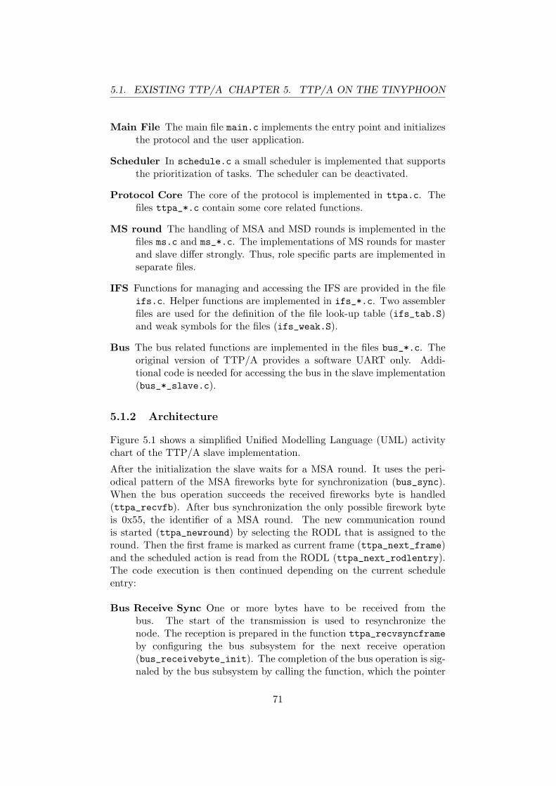
5.1. EXISTING TTP/A CHAPTER 5. TTP/A ON THE TINYPHOON
Main File The main file main.c implements the entry point and initializesthe protocol and the user application.
Scheduler In schedule.c a small scheduler is implemented that supportsthe prioritization of tasks. The scheduler can be deactivated.
Protocol Core The core of the protocol is implemented in ttpa.c. Thefiles ttpa_*.c contain some core related functions.
MS round The handling of MSA and MSD rounds is implemented in thefiles ms.c and ms_*.c. The implementations of MS rounds for masterand slave differ strongly. Thus, role specific parts are implemented inseparate files.
IFS Functions for managing and accessing the IFS are provided in the fileifs.c. Helper functions are implemented in ifs_*.c. Two assemblerfiles are used for the definition of the file look-up table (ifs_tab.S)and weak symbols for the files (ifs_weak.S).
Bus The bus related functions are implemented in the files bus_*.c. Theoriginal version of TTP/A provides a software UART only. Addi-tional code is needed for accessing the bus in the slave implementation(bus_*_slave.c).
5.1.2 Architecture
Figure 5.1 shows a simplified Unified Modelling Language (UML) activitychart of the TTP/A slave implementation.
After the initialization the slave waits for a MSA round. It uses the peri-odical pattern of the MSA fireworks byte for synchronization (bus_sync).When the bus operation succeeds the received fireworks byte is handled(ttpa_recvfb). After bus synchronization the only possible firework byteis 0x55, the identifier of a MSA round. The new communication roundis started (ttpa_newround) by selecting the RODL that is assigned to theround. Then the first frame is marked as current frame (ttpa_next_frame)and the scheduled action is read from the RODL (ttpa_next_rodlentry).The code execution is then continued depending on the current scheduleentry:
Bus Receive Sync One or more bytes have to be received from thebus. The start of the transmission is used to resynchronize thenode. The reception is prepared in the function ttpa_recvsyncframeby configuring the bus subsystem for the next receive operation(bus_receivebyte_init). The completion of the bus operation is sig-naled by the bus subsystem by calling the function, which the pointer
71
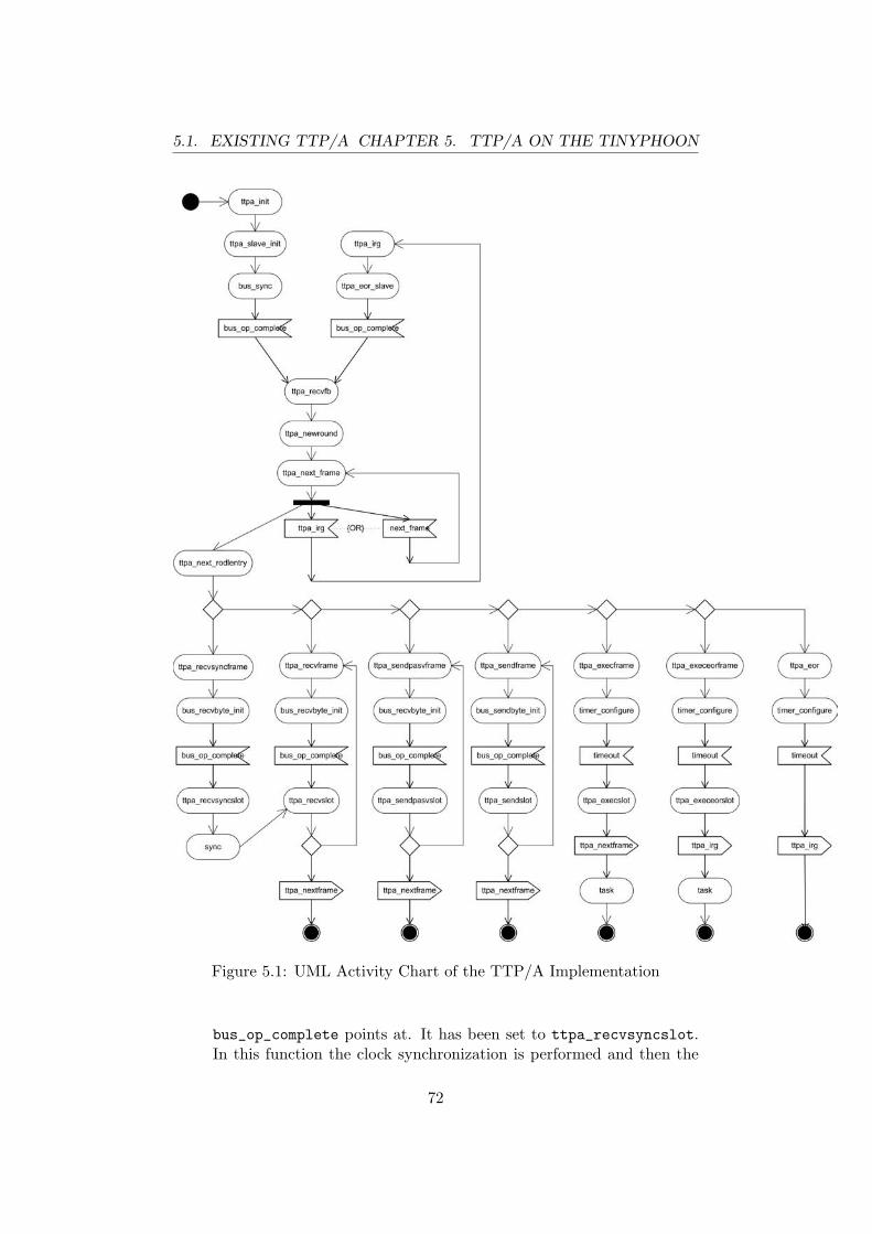
5.1. EXISTING TTP/A CHAPTER 5. TTP/A ON THE TINYPHOON
Figure 5.1: UML Activity Chart of the TTP/A Implementation
bus_op_complete points at. It has been set to ttpa_recvsyncslot.In this function the clock synchronization is performed and then the
72

5.1. EXISTING TTP/A CHAPTER 5. TTP/A ON THE TINYPHOON
handler for received bytes, ttpa_recvslot, is called. If there are morebytes that have to be received, the normal receive operation (see nextparagraph) is performed. Otherwise, a new frame is started.
Bus Receive This operation is the same as the one described above, butno clock synchronization is performed.
Bus Send Passive This operation is performed in the send slots of thenode when the node tries to integrate itself in the cluster. It is usedat start-up or after an error. The node tries to receive somethingin its send slots to ensure that no other node uses these slots fortransmissions. Thus, collisions due to wrong configurations can beavoided. First ttpa_sendpasvframe configures the bus subsystem(bus_recvbyte_init) for receiving and waits for the completion ofthis operation. Then ttpa_sendpasvslot is called. If the receive op-eration was not successful, the slot is empty and the node can use itfor transmissions. If there are more slots to be tested, this operationis repeated, otherwise the handling of the next frame is started.
Bus Send Once the node has verified, that its send slot is free,it uses this operation to transmit data in the slot. Inttpa_sendbyte_init the bus subsystem is configured for a transmis-sion (bus_send_byte_init). After the completion of the bus opera-tion, ttpa_sendslot is called. If more bytes have to be transmitted,the send operation is repeated. Otherwise, otherwise the handling ofthe next frame is started.
Execute This operation executes a task that has either been defined by theapplication or by the protocol (e. g., for handling MS rounds). In thefunction ttpa_execframe a timer is configured to generate a time-outevent at the start of the time slot. After the time-out the functionttpa_execslot is called. It triggers the preparation of the next frameand then performs the configured task.
Execute at the End of the Round Also the IRG can be used for exe-cuting tasks. This operation is almost the same as the normal executeoperation but it signals the end of a communication round instead ofpreparing the next frame.
End of the Round If the communication round is finished and no taskexecution is scheduled for the IRG, tis operation is performed. Inttpa_eor a timer is configured to trigger the start of a new round atthe appropriate point of time.
After the processing of the frame either a new frame or a new communi-cation round is started. In the first case ttpa_next_frame is called and
73

5.1. EXISTING TTP/A CHAPTER 5. TTP/A ON THE TINYPHOON
the next scheduled action is read from the RODL (ttpa_next_rodlentry).In the second case the slave node executes the function ttpa_eor_slavethat configures the bus subsystem for the reception of a new fireworksbyte. As soon as the bus operation is finished, the fireworks byte is inter-preted (ttpa_fbrecv) and the according communication round is started(ttpa_newround).
5.1.3 Bus Subsystem
The read and write operations on the bus are performed through the bussubsystem. This design decision makes it easy to integrate new implementa-tions of the bus access. Listing 5.1 shows the interface of the bus subsystemthat is defined in bus.h.
int bus_init(void);void bus_sendbyte_init(bus_iobuf_t *param);void bus_recvbyte_init(bus_iobuf_t *param);void bus_sync(void);void (* volatile bus_op_complete) (bus_iobuf_t *);
Listing 5.1: Interface of the Bus Subsystem
The interface defines function for initializing the bus subsystem and for ini-tiating a transmission or a reception of a byte. On slave nodes an additionalfunction for synchronizing with the bus has to be implemented. A pointerbus_op_complete has to be set to a function that is called after the busoperation has been finished. The configuration and the result of a bus op-eration is stored in the structure bus_iobuf_t. Listing 5.2 shows the fieldsof this structure.
typedef struct bus_iobuf_t uint8_t buf;parity_t par;uint16_t slotstart;union status_t
struct fields_t unsigned spdup : 3;unsigned timeout : 1;
fields;bus_io_err_t error;
status; bus_iobuf_t;
Listing 5.2: Structure for Bus Operations
74

5.2. HW UART CHAPTER 5. TTP/A ON THE TINYPHOON
The field uint8_t buf stores the byte that has to be transmitted or thathas been received. The field parity_t par is an enumeration type thatspecifies the parity. The number of the microtick when a byte has tobe transmitted or has been received is stored in uint16_t slot_start.The union status stores a speed-up factor and a timeout flag, when thestructure is used for the configuration of a bus operation, or an error fieldwhen the structure is used for returning the result of an operation.
5.2 Hardware UART Implementation
The TTP/A implementation originally uses a UART that is implementedin software. This ensures a very precise synchronization because an inputcapture logic is used to detect the start of a transmission with the precisionof one internal micro tick. However, the software implementation needs oneinterrupt for every bit. This leads to a high interrupt load even at smallbit rates and influences coexisting applications on the same microcontroller.Thus, the bus interface has also been implemented using a hardware UART.Due to the schematics of the Tinyphoon’s modules only this implementationcan be used for the communication.
The source code shown in the next sections 5.2.1 and 5.2.2 has been designedto work with the Hardware Abstraction Layer (HAL) proposed in section5.3.2. All hardware specific parts are replaced by the call of a macro.
5.2.1 Receiving
The code for receiving a byte from the bus is divided in four functions anda interrupt service routine.
The first function is part of the bus interface and is called by the TTP/Acore code to initiate the reception of a byte in the next time slot. Thefunction bus_recvbyte_init has a parameter of the type bus_iobuf_t *(see listing 5.3). It stores the time-out of this parameter in its own datastructure, sets the global pointer for the timer callback to the setup func-tion and configures the timer to raise an interrupt on the start of the nextslot. HAL_HW_UART_RECV_SU_CORR can be used to correct a possible delayof the hardware UART. Then, the function bus_transcvr_recv switches apossible transceiver to receive mode, if needed. The UART receive interruptis still disabled.
void bus_recvbyte_init(bus_iobuf_t *param)
bus_hwuart_buf.timeout =
75

5.2. HW UART CHAPTER 5. TTP/A ON THE TINYPHOON
param ->status.fields.timeout;
ttpa_sig_oc = (void (*)()) bus_recvbyte_setup;
hal_set_timer_compare_value(param ->slotstart +HAL_HW_UART_RECV_SU_CORR + ttpa_bitlength );
hal_delete_compare_match_interrupt ();hal_enable_compare_match_interrupt ();
bus_transcvr_recv ();
hal_uart_rx_disable ();
Listing 5.3: HW UART Receive Initialization
On the start of the time slot bus_recvbyte_setup is called (see listing 5.4).The expected transmission starts one bit time after the call of this function.First the reception of bytes is enabled and the output compare logic isconfigured to generate a match event 12.5 bit times after the start of theslot. Following, the call back that is called, when a byte is received by theUART, is set to bus_recvbyte.
The bus subsystem has to implement two modes of byte reception, one withtime-out and another without a time-out. In the case that a time-out isused, the pointer for the callback of the compare match interrupt is set tobus_recvbyte_to and the interrupt is enabled. Otherwise, the interrupt isdisabled.
At the end of the function pending UART receive interrupts are cleared andthe interrupt is enabled.
void bus_recvbyte_setup(void)hal_uart_rx_enable ();hal_inc_timer_compare_value (12 * ttpa_bitlength +
ttpa_bitlength >>1);bus_uart_recv = bus_recvbyte;
if(bus_hwuart_buf.timeout) ttpa_sig_oc = (void (*)()) bus_recvbyte_to;hal_delete_compare_match_interrupt ();hal_enable_compare_match_interrupt ();
else hal_disable_compare_match_interrupt ();
hal_delete_uart_receive_interrupt ();
76
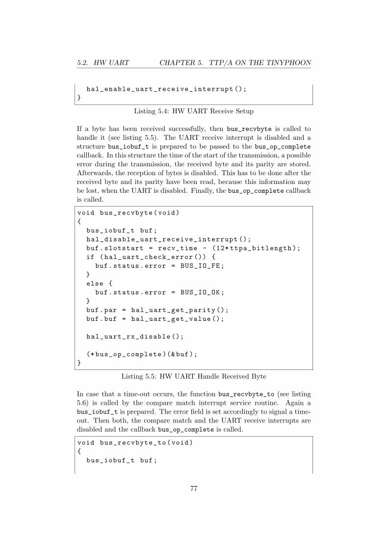
5.2. HW UART CHAPTER 5. TTP/A ON THE TINYPHOON
hal_enable_uart_receive_interrupt ();
Listing 5.4: HW UART Receive Setup
If a byte has been received successfully, then bus_recvbyte is called tohandle it (see listing 5.5). The UART receive interrupt is disabled and astructure bus_iobuf_t is prepared to be passed to the bus_op_completecallback. In this structure the time of the start of the transmission, a possibleerror during the transmission, the received byte and its parity are stored.Afterwards, the reception of bytes is disabled. This has to be done after thereceived byte and its parity have been read, because this information maybe lost, when the UART is disabled. Finally, the bus_op_complete callbackis called.
void bus_recvbyte(void)
bus_iobuf_t buf;hal_disable_uart_receive_interrupt ();buf.slotstart = recv_time - (12* ttpa_bitlength );if (hal_uart_check_error ())
buf.status.error = BUS_IO_FE;else
buf.status.error = BUS_IO_OK;buf.par = hal_uart_get_parity ();buf.buf = hal_uart_get_value ();
hal_uart_rx_disable ();
(* bus_op_complete )(& buf);
Listing 5.5: HW UART Handle Received Byte
In case that a time-out occurs, the function bus_recvbyte_to (see listing5.6) is called by the compare match interrupt service routine. Again abus_iobuf_t is prepared. The error field is set accordingly to signal a time-out. Then both, the compare match and the UART receive interrupts aredisabled and the callback bus_op_complete is called.
void bus_recvbyte_to(void)
bus_iobuf_t buf;
77

5.2. HW UART CHAPTER 5. TTP/A ON THE TINYPHOON
buf.status.error = BUS_IO_TIMEOUT;
hal_delete_compare_match_interrupt ();hal_enable_compare_match_interrupt ();hal_disable_uart_receive_interrupt ();
(* bus_op_complete )(& buf);
Listing 5.6: HW UART Receive Time-Out
The last piece of the hardware UART implementation for the reception ofbytes is the interrupt service routine for the UART receive interrupt (seelisting 5.7). It stores the time of the reception of the byte and adds acorrection value to consider the different delays of different hardware UART.Then the callback, which the pointer bus_op_complete points at is called.
hal_uart_receive_interrupt ()
recv_time = hal_get_timer ();recv_time += HAL_HW_UART_RECV_CORR;(* bus_uart_recv )();
Listing 5.7: HW UART Receive Interrupt
5.2.2 Sending
The implementation for sending bytes is realized in two functions. The firstone is called by the TTP/A core to configure the transmission of a byte forthe next time slot. The second is used internally as callback for the timer,when the transmission starts.
The function bus_sendbyte_init (see listing 5.8) is part of the bus inter-face. It initiates the transmission of a byte at the beginning of the next timeslot. The byte to be transmitted, its parity and the start of the next timeslot is passed to the function in a bus_iobuf_t structure.
The parameters for the transmission are copied to local data structuresand the callback for the compare match interrupt service routine is set tobus_sendbyte. Then, the compare value is set accordingly, so that thecompare match interrupt is raised exactly when the transmission has to bestarted. Possibly pending compare match interrupts are deleted and theinterrupt is enabled. Finally, a possible transceiver is switched to transmitmode.
78
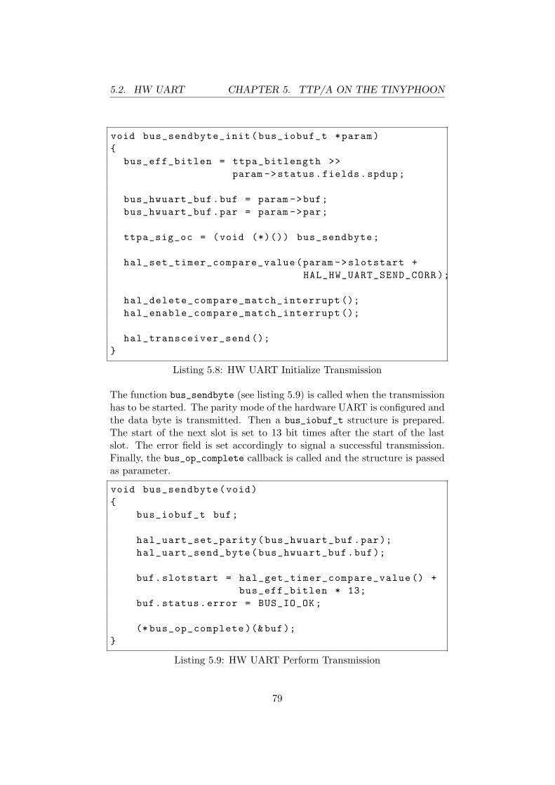
5.2. HW UART CHAPTER 5. TTP/A ON THE TINYPHOON
void bus_sendbyte_init(bus_iobuf_t *param)
bus_eff_bitlen = ttpa_bitlength >>param ->status.fields.spdup;
bus_hwuart_buf.buf = param ->buf;bus_hwuart_buf.par = param ->par;
ttpa_sig_oc = (void (*)()) bus_sendbyte;
hal_set_timer_compare_value(param ->slotstart +HAL_HW_UART_SEND_CORR );
hal_delete_compare_match_interrupt ();hal_enable_compare_match_interrupt ();
hal_transceiver_send ();
Listing 5.8: HW UART Initialize Transmission
The function bus_sendbyte (see listing 5.9) is called when the transmissionhas to be started. The parity mode of the hardware UART is configured andthe data byte is transmitted. Then a bus_iobuf_t structure is prepared.The start of the next slot is set to 13 bit times after the start of the lastslot. The error field is set accordingly to signal a successful transmission.Finally, the bus_op_complete callback is called and the structure is passedas parameter.
void bus_sendbyte(void)
bus_iobuf_t buf;
hal_uart_set_parity(bus_hwuart_buf.par);hal_uart_send_byte(bus_hwuart_buf.buf);
buf.slotstart = hal_get_timer_compare_value () +bus_eff_bitlen * 13;
buf.status.error = BUS_IO_OK;
(* bus_op_complete )(& buf);
Listing 5.9: HW UART Perform Transmission
79

5.3. PORTABLE TTP/ACHAPTER 5. TTP/A ON THE TINYPHOON
5.3 Portable TTP/A Implementation
Based on the description of the TTP/A implementation above, an architec-ture and modifications of the source code are proposed in this section, tomake the main part of the C implementation independent from the targetplatform. The adoptions are minimized and pooled in two files, one forthe processor architecture and one for the concrete hardware of the node(including processor model and I/O configuration).
5.3.1 Compiler Independence
Many hardware platforms are only supported by a single compiler and thereis no universal compiler. Therefore, a portable source code has to be writtenin a way, that as many compilers as possible are able to compile it correctly.These compilers are often very specialized, limited and/or proprietary. How-ever, every modern compiler is at least compatible to the C standard ofANSI. Source code that does not use any other C constructs than definedby this standard is understood by most of the compilers. Thus, the firststep of creating a portable version of TTP/A is replacing constructs thatare not compliant with the ANSI C standard. Especially constructs for thedefinition and initialization of complex data types (e. g., anonymous struc-tures, initialization of selected fields of a structure, ...) that are supportedby the GCC are not part of the ANSI C standard.
5.3.2 Hardware Abstraction Layer
To make the source code independent from the hardware the implementa-tion of a HAL is proposed. The HAL defines a standardized interface tothe hardware at a very low level of abstraction. The level has to be thatlow, because portability has not been considered consequently during designphase of the implementation. One the one hand there is an interface to thebus subsystem that allows a high level of abstraction. It would allow driverlike implementation of the bus subsystem. On the other hand the timerused by TTP/A is read, written and configured in several protocol states.Moreover, in the current source code the timer hardware is accessed directly,there is no abstract software interface.
Figure 5.2 shows the proposed architecture for a portable version of aTTP/A implementation.
The HAL is implemented using macros. The advantage of macros is that itis guaranteed, that no overhead is added to the code. Almost all compilersunderstand macros. Another possibility is the use of inline functions. Acompiler can check the syntax of a call of an inline function in contrast to
80
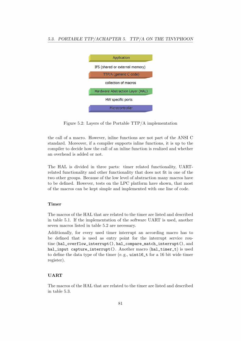
5.3. PORTABLE TTP/ACHAPTER 5. TTP/A ON THE TINYPHOON
Figure 5.2: Layers of the Portable TTP/A implementation
the call of a macro. However, inline functions are not part of the ANSI Cstandard. Moreover, if a compiler supports inline functions, it is up to thecompiler to decide how the call of an inline function is realized and whetheran overhead is added or not.
The HAL is divided in three parts: timer related functionality, UART-related functionality and other functionality that does not fit in one of thetwo other groups. Because of the low level of abstraction many macros haveto be defined. However, tests on the LPC platform have shown, that mostof the macros can be kept simple and implemented with one line of code.
Timer
The macros of the HAL that are related to the timer are listed and describedin table 5.1. If the implementation of the software UART is used, anotherseven macros listed in table 5.2 are necessary.
Additionally, for every used timer interrupt an according macro has tobe defined that is used as entry point for the interrupt service rou-tine (hal_overflow_interrupt(), hal_compare_match_interrupt(), andhal_input capture_interrupt(). Another macro (hal_timer_t) is usedto define the data type of the timer (e. g., uint16_t for a 16 bit wide timerregister).
UART
The macros of the HAL that are related to the timer are listed and describedin table 5.3.
81

5.3. PORTABLE TTP/ACHAPTER 5. TTP/A ON THE TINYPHOON
Macro Descriptionhal_configure_timer() Configures timer for use with
TTP/Ahal_set_timer(value) Sets TTP/A timer/counter to
valuehal_get_timer() Sets TTP/A timer/counter to
valuehal_set_timer_compare_value(value) Sets TTP/A timer/counter
compare register to valuehal_inc_timer_compare_value(value) Sets TTP/A timer/counter
compare register to valuehal_get_timer_compare_value() Sets TTP/A timer/counter
compare register to valuehal_delete_compare_match_interrupt() Deletes eventually pending
timer overflow interrupthal_enable_compare_match_interrupt() Enables timer overflow inter-
rupthal_disable_compare_match_interrupt() Disables timer overflow inter-
rupthal_delete_overflow_interrupt() Deletes eventually pending
timer overflow interrupthal_enable_overflow_interrupt() Enables timer overflow inter-
rupthal_disable_overflow_interrupt() Disables timer overflow inter-
rupthal_delete_input_capture_interrupt() Deletes eventually pending
timer overflow interrupt
Table 5.1: Timer HAL Macros
Other Issues
Some more macros are defined in the HAL for accessing to Flash memoryand Electrically Erasable Programmable Read-Only Memory (EEPROM),for enabling and disabling interrupts, for configuring the node, for readingthe I/O pin for the software UART and for controlling a possible, externaltransceiver. These macros are described in table 5.4, 5.5, 5.6, and 5.7.
The macros for accessing the EEPROM may be defined as constant numbersif on a particular platform no EEPROM is available. The parts of the codefor accessing the EEPROM is never executed, if no files of the IFS areconfigured to be stored in the EEPROM.
The macros related to the transceiver may be empty if no transceivers areused that need to be switched between transmit and receive mode.
82

5.3. PORTABLE TTP/ACHAPTER 5. TTP/A ON THE TINYPHOON
Macro Descriptionhal_enable_input_capture_interrupt() Enables timer input capture
interrupthal_disable_input_capture_interrupt() Disables timer input capture
interrupthal_set_input_capture_falling_edge() Configures input capture
mechanism to trigger on afalling edge
hal_set_input_capture_raising_edge() Configures input capturemechanism to trigger on araising edge
hal_set_input_capture_toggle_edge() Configures input capturemechanism to trigger on anyedge
hal_get_input_capture_value() Reads value from input cap-ture register
hal_set_pin_on_compare_match(value) Configures compare matchlogic to set pin state to valueon next match event
Table 5.2: Additional Timer HAL Macros for the Software UART
5.3.3 Linker Script
A special linker script is used for generating special sections for the IFS anda table of tasks that is executed during the initialization. The linker scriptstrongly depends on the used platform and of the linker. Thus it has tobe changed accordingly. Unfortunately, at the time of writing there is nodocumentation about the layout of these sections available.
The according linker file for a target platform have to be created using thelinker file of the available implementation as example. For many linkergraphical tools exist, which allow a convenient adaptation of the linker files.In many cases linker files have to be created for new projects anyway.
83

5.3. PORTABLE TTP/ACHAPTER 5. TTP/A ON THE TINYPHOON
Macro Descriptionhal_uart_configure() Configures the UARThal_uart_set_parity(value) Sets parity mode to even or to
oddhal_uart_rx_disable() Disables reception of bytes (of-
ten also the received data iscleared)
hal_uart_rx_enable() Enables reception of byteshal_uart_send_byte(value) Transmits the byte valuehal_uart_get_value() Returns last byte receivedhal_uart_check_error() Checks whether an error oc-
curred during reception of thelast byte
hal_uart_get_parity() Returns parity of the last bytereceived
hal_uart_receive_interrupt() Header of UART receive inter-rupt
hal_delete_uart_receive_interrupt() Deletes possibly pendingUART receive interrupt
hal_enable_uart_receive_interrupt() Enables UART receive inter-rupt
hal_disable_uart_receive_interrupt() Disables UART receive inter-rupt
Table 5.3: UART HAL Macros
Macro Descriptionhal_progmem_read_byte() Reads a byte from the pro-
gram memory (usually flashROM)
hal_progmem_read_word() Reads a word from the pro-gram memory (usually flashROM)
hal_eeprom_is_ready() Returns true if the EEPROMis ready for a read or write op-eration
hal_eeprom_read_byte() Reads a byte from the EEP-ROM
Table 5.4: HAL Macros for Memory Access
84

5.3. PORTABLE TTP/ACHAPTER 5. TTP/A ON THE TINYPHOON
Macro Descriptionhal_enable_interrupts() Globally enables interruptshal_disable_interrupts() Globally disables interrupts
Table 5.5: HAL Macros for En-/Disabling Interrupts
Macro Descriptionhal_configure_swuart_io() Configures the I/O pins used
by the software UARThal_configure_node_swuart() Performs node specific config-
uration that is related to thesoftware UART
hal_configure_hwuart() Performs general configura-tion that is related to thehardware UART
hal_configure_node_hwuart() Performs node specific config-uration that is related to thehardware UART
hal_sw_uart_rxpin_is_high() Tests whether the receive pinof the software UART is at ahigh level
Table 5.6: HAL Macros for the Node and I/O Configuration
Macro Descriptionhal_init_transceiver() Initializes the transceiverhal_transceiver_recv() Switches the transceiver to re-
ceive modehal_transceiver_send() Switches the transceiver to
transmit mode
Table 5.7: HAL Macros for Controlling an External Transceiver
85
5.4. EVALUATION CHAPTER 5. TTP/A ON THE TINYPHOON
5.4 Evaluation
To evaluate the proposed HAL architecture on the one hand and the ap-plicability of TTP/A on the current Tinyphoon hardware TTP/A has beenported to the LPC 2119 from Philips Semiconductors3. The experiencesgained during porting have been used to improve the HAL architecture andto suggest improvements of the TTP/A protocol that make it even moresuitable for the use on small autonomous robots.
5.4.1 TTP/A on the LPC 2119
The LPC 2119[Phi06] microcontroller bases upon the ARM7 core. It hasbeen selected to be used on the Tinyphoon because of its powerful archi-tecture despite its small footprint. It features the standard peripherals ofa typical microcontroller (UART, timers with input capture and comparematch logic, I/O ports, I2C and CAN bus, ...).
A test cluster consisting of a master and a slave node has been build. TheWinARM version of the ARM GCC 4.0.2 has been used for the develop-ment. The original TTP/A implementation also has been written for aversion of the GCC. Thus, all compiler extensions that are not supportedby the ANSI C standard have been disabled to emulate a compiler thatunderstands ANSI C constructs only.
During the implementation of the HAL some problems had to be solved:
• The AVR platform supports at most 16-bit wide timers whereas thetimer registers of the LPC 2119 are 32 bit wide. A special data typehas been defined that has the same bit width as the timer registers.Whenever the value of a timer is stored in a variable, this data typehas to be used.
• The timers of the LPC 2119 can not raise an interrupt when the timerregister overflows. Thus, this behavior has to be emulated using an-other compare match unit.
• The interrupt concept of the LPC 2119 is much more complex thanthat of the AVR microcontrollers. The macros have been designedin a way to support both of them. However, on platforms with acomplex interrupt logic some additional steps might be necessary tillthe interrupt service routine is called correctly (e. g., entries in linkerand/or start-up files, modifications of interrupt vector table, ...
3now NXP, http://www.nxp.com
86

5.4. EVALUATION CHAPTER 5. TTP/A ON THE TINYPHOON
• The timings might vary from one platform to another (e. g., the UARTreceive interrupt is raised earlier or later after the reception of a byte).To solve this problem correction values are used in the critical partsof the source code.
• The adaption of the linker file turned out to be a very cumbersomejob.
• The implementation of the hardware UART has not improved themaximum performance as expected. The reason for this behavior is,that the action for the next frame is prepared in the inter frame gapafter the previous bus operation has been finished. The implemen-tation of the software UART stops the reception of a byte after theraising edge of the stop bit has been detected. In contrast the hard-ware UART samples mid of the stop bit and then raises the receiveinterrupt. Therefore, the preparation time for the next slot is evenshorter and the maximum baud rate is smaller than that of the imple-mentation using a software UART.
5.4.2 Suggested Improvements of TTP/A
The suggestions are based on the issues that came up during porting andtesting TTP/A on the hardware of the Tinyphoon. The problems aregrouped in three categories: enhancing performance, improving the han-dling of large chunks of data and avoiding the use of linker scripts.
Enhancing Performance
A hardware UART has been implemented in order to improve the perfor-mance of TTP/A while the load of the microcontroller is reduced. However,tests have shown, that on the AVR platform the hardware UART configura-tion (up to 16000 bit/s) does not even reach the performance of the versionusing the software UART (up to 19200 bit/s).
The different way of stop bit detection in combination with the way ofpreparing the next byte frame causes this problem. The hardware UARTgenerates a receive interrupt after the stop bit has been sampled in themiddle of the bit, whereas the software UART stops receiving as soon theraising edge of the stop bit has been detected. The preparation of the nextframe slot is started as soon as the reception or transmission of the lastslot has been completed. Thus, the preparation time is shorter when thehardware UART is used.
To solve this problem the preparation of next frame slot can be startedwhile the preceding frame is still being received or transmitted. In this
87

5.4. EVALUATION CHAPTER 5. TTP/A ON THE TINYPHOON
moment the communication is completely handled by the hardware UART.Therefore, the computing power of the CPU can be used for the preparation.
The frames of TTP/A are 13 bits long. but the maximum length of a trans-mission with a hardware UART is twelve bits (one start bit, eight data bits,one parity bit and two stop bits). Thus, a continuous transmission usinga standard hardware UART is impossible. This restriction impedes theexploitation of the powerful features of more enhanced hardware UART thatallow the transmission of multiple bytes without the interaction of the CPU.
Moreover, the transmission of every byte has to be triggered by a timer. Onethe one hand this increases the load on the CPU(e. g., timer configuration,interrupt handling) on the other hand not only the start of a transmissionbut the complete transmission is closely related to the timing, which makesa separate implementation of the UART and the timer subsystems hardlypossible. Hence, the code lacks portability.
Handling of Large Data Packets
TTP/A has been designed as communication protocol for smart transduc-ers. The protocol is adequate for exchanging small amounts of data. Itcauses only a little overhead but only supports frames with the length ofone byte. Though many frames can be scheduled consecutively to avoidfragmentation of the payload, TTP/A provides no means to check the in-tegrity of the complete payload. Thus, the application has to ensure, thatall bytes of the payload have been communicated successfully. A checksummechanism as provided by LIN would reduce the effort for the applicationdesign. Additionally, the encapsulation of an integrity check in the protocolensures the compatibility thereof among all TTP/A nodes.
Linker Scripts
Linker scripts are highly hardware and linker dependent. The process ofporting TTP/A also includes the complex adaption of the linker scripts.This effort only can be reduced by avoiding linker scripts. The currentversion of the TTP/A implementation uses them heavily for providing acomfortable programming interface while keeping memory requirements low.
In the future configuration tools will be available that can configure the IFSand the RODL of TTP/A nodes. Hence, there programming interface willnot be used by the programmer directly and can be designed in a way thatno linker scripts are needed.
88

A conclusion is the placewhere you got tired thinking.
Martin H. FischerAmerican (German-born) Physician and Author (1879 - 1962)
Chapter 6
Conclusion
This chapter summarizes the contribution of this thesis and gives an outlookon future work in the covered domain.
6.1 Contribution of This Thesis
This thesis has described the five real-time protocols CAN, LIN, Flexray,TTP/C, and TTP/A in detail. The comparison of the protocols alsoconsiders the special needs of small autonomous systems. All importantcharacteristics are listed in table form and the main attributes are alsocompared in a diagram.
The communication requirements of the subsystems of the Tinyphoon robothave been analyzed. Each subsystem and the data it needs or provideshas been described. This analysis of the communication on the Tinyphoonhas shown, that real-time features (e. g., predictable communication, smalljitter, global time) improve the interaction of the subsystems and allownew approaches of application design. Fault tolerance is not an issue onsmall robots but a high data throughput and the maintainability of thecommunication system are vitally important.
CAN and LIN lack some of the important real-time features whereasFlexray and TTP/C are very complex. TTP/A combines the basicreal-time features with a small implementation footprint. Its standardizeddebugging and configuration interface allows the observation of the commu-nication and the platform-independent tuning of the configuration of eachsubsystem. TTP/A is implemented in software and coexists with otherapplications, which saves valuable space on the PCB. Moreover, the sourcecode of TTP/A is available for free. Because of these features TTP/A has
89
6.2. OUTLOOK CHAPTER 6. CONCLUSION
been evaluated on the Tinyphoon robot.
Based on an analysis of the mode of operation of the current TTP/Aimplementation an architecture for making TTP/A portable is proposed.A HAL has been designed and implemented on the original platform of theTTP/A implementation. A case study on the hardware of the Tinyphoonrobot has proved the capability of this concept and that TTP/A can beused for the communication on small autonomous systems.
Based on the evaluation of this case study a proposal for further improve-ments of TTP/A have been derived. Methods have been proposed to makeTTP/A easier to port to new hardware platforms and to make it even moresuitable for the use on small autonomous systems like the Tinyphoon robot.
6.2 Outlook to Future Work
Currently a new protocol based on TTP/A is being developed. Itsperformance will be boosted by supporting the application of the advancedfeatures of modern, powerful UART hardware units. The protection ofdata frames with a checksum will ease the handling of large chunks of data.This protocol will suit the needs of small autonomous systems even betterthan TTP/A.
The communication architecture of the Tinyphoon robot has to be revised inthe future. The current implementations of the subsystems are designed ac-cording to the event-triggered paradigm. With the introduction of a globaltime base the complete system can be synchronized. Hence, all measure-ments on the robot can be triggered at the same point in time, whichmakes the fusion of the result considerably easier. Therefore, we plan tointegrate real-time communication on the Tinyphoon robot and to use atime-triggered software design.
In the future the wireless communication system of the Tinyphoon robot canbe used to synchronize measurements within a group of robots. This sim-plifies the exchange and the interpretation of data about their environment.Thus, a distributed world model of all robots can be established.
The separation of the communication protocol from the application reducesthe effort of maintaining the source code. The communication system canbe added to the software of new subsystems easily.
90

Bibliography
[ANS89] ANSI – American National Standard Institute. Ansi standardx3.159-1989, December 1989.
[Atm05] Atmel Corporation. Application note AVR322: LIN v1.3 protocolimplementation on atmel avr microcontrollers, 05 2005.
[BAS+06] M. Bader, M. Albero, R. Sablatnig, J. E. Simo, G. Benet, G. No-vak, and F. Blanes. ”embedded real-time ball detection unit forthe yabiro biped robot”. In ”Fourth Workshop on Intelligent Solu-tions in Embedded Systems (WISES’06)”, Vienna, Austria, 2006.
[DEE03] Martin Delvai, Ulrike Eisenmann, and Wilfried Elmenreich. Ageneric architecture for integrated smart transducers. In Proceed-ings of the 13th International Conference on Field ProgrammableLogic and Applications, Lecture Notes in Computer Science, Lis-boa, Portugal, September 2003. Springer Verlag.
[Dev06] Analog Devices. Datasheet Blackfin 561, 2006.
[EEE+01] Stephan Eberle, Christian Ebner, Wilfried Elmenreich, GeorgFarber, Peter Gohner, Wolfgang Haidinger, Michael Holzmann,Robert Huber, Ralf Schlatterbeck, Hermann Kopetz, and AlecStothert. Specification of the ttp/a protocol. Research Report61/2001, Technische Universitat Wien, Institut fur Technische In-formatik, Treitlstr. 1-3/182-1, 1040 Vienna, Austria, 2001.
[EHK+02] Wilfried Elmenreich, Wolfgang Haidinger, Raimund Kirner,Thomas Losert, Roman Obermaisser, and Christian Trodhandl.TTP/A smart transducer programming - a beginner’s guide. Re-search Report 33/2002, Technische Universitat Wien, Institut furTechnische Informatik, Treitlstr. 1-3/182-1, 1040 Vienna, Austria,2002.
[EHPS02] Wilfried Elmenreich, Wolfgang Haidinger, Philipp Peti, andLukas Schneider. New node integration for master-slave fieldbus
91
BIBLIOGRAPHY BIBLIOGRAPHY
networks. In Proceedings of the 20th IASTED International Con-ference on Applied Informatics (AI 2002), pages 173–178, Feb.2002.
[EK04] Wilfried Elmenreich and Stefan Krywult. Comparison of fieldbusprotocols LIN 1.0, LIN 2.0, and TTP/A. Research Report 3/2004,Technische Universitat Wien, Institut fur Technische Informatik,Treitlstr. 1-3/182-1, 1040 Vienna, Austria, 2004.
[Fle05a] FlexRay Consortium. FlexRay communication system, electricalphysical layer specification, version 2.0, 2005.
[Fle05b] FlexRay Consortium. FlexRay communication system, protocolspecification, version 2.0, 2005.
[FMD+00] Thomas Fuhrer, Bernd Muller, Werner Dieterle, FlorianHartwich, Robert Hugel, Michael Walther, and Robert BoschGmbH. Time triggered communication on CAN. In Proceedingsof the 7th International CAN Conference, Amsterdam, 2000.
[HH00] Wolfgang Haidinger and Robert Huber. Generation and analysisof the codes for TTP/A fireworks bytes. Research Report 5/2000,Technische Universitat Wien, Institut fur Technische Informatik,Treitlstr. 1-3/182-1, 1040 Vienna, Austria, 2000.
[HMFH00] Florian Hartwich, Bernd Muller, Thomas Fuhrer, and RobertHugel. CAN network with time triggered communication. In Pro-ceedings of the 7th International CAN Conference, Amsterdam,2000.
[IEE90] IEEE – Institute of Electrical and Electronics Engineers. Ieeestandard 1149.1: Standard test access port and boundary-scanarchitecture, 1990.
[ISO04] ISO – International Organization for Standardization. Road ve-hicles – controller area network (CAN) – Part 4: Time-triggeredcommunication, 2004.
[KHK+96] H. Kopetz, R. Hexel, A. Kruger, D. Millinger, and A. Schedl.A synchronization strategy for a TTP/C controller. In Appli-cation of Multiplexing Technology (SP-1137), Detroid, MI, USA,February 1996. Society of Automotive Engineers, SAE Press.
[KO03] H. Kopetz and W. Ochsenreiter. Clock synchronization in dis-tributed real-time systems. In IEEE Transactions on Computers,pages 933–940, August 2003.
92

BIBLIOGRAPHY BIBLIOGRAPHY
[Kop97] Kopetz. Real-time systems: design principles for distributed em-bedded applications. Kluwer Academic Publishers, 1997.
[Kop01] Hermann Kopetz. A comparison of TTP/C and FlexRay. Re-search Report 10/2001, Technische Universitat Wien, Institut furTechnische Informatik, Treitlstr. 1-3/182-1, 1040 Vienna, Austria,2001.
[KS04a] Stefan Krywult and Christian Steiner. Survey on present real-time ethernet solutions. Research Report 12/2004, TechnischeUniversitat Wien, Institut fur Technische Informatik, Treitlstr.1-3/182-1, 1040 Vienna, Austria, 2004.
[KS04b] Stefan Krywult and Christian Steiner. TTP/A gateway. Re-search Report 37/2004, Technische Universitat Wien, Institut furTechnische Informatik, Treitlstr. 1-3/182-1, 1040 Vienna, Austria,2004.
[LIN03] LIN Consortium. LIN Specification Package, Revision 2.0,September 2003.
[LL84] J. Lundelius and N. Lynch. A new fault-tolerant algorithm forclock synchronization. In Proceedings of PODC ’84, New York,NY, USA, 1984. ACM Press.
[MON05] S. Mahlknecht, R. Oberhammer, and G. Novak. ”real-time imagerecognition system for tiny autonomous mobile robots”. Real-Time Systems, 29, 2005.
[NM05] G. Novak and S. Mahlknecht. Tinyphoon - a tiny autonomous mo-bile robot. Technical report, Institute for Computer Technology,Vienna Universitys of Technology, Vienna, Austria, 2005.
[OMG02] OMG – Object Management Group. Smart transducers interfacespecification v1.0 – ptc/2002-10-02, 08 2002.
[Phi06] Philips. Datasheet LPC2119, 2006.
[Sie06] Siemens. Datasheet XC167, 2006.
[SJ05] M. Seyr and S. Jakubek. ”mobile robot predictive trajectorytracking”. In Proceedings of the 2005 ICINCO, ICINCO, 2005.
[SJN05] M. Seyr, S. Jakubek, and G. Novak. Neural network predictivetrajectory tracking of an autonomous two-wheeled mobile robot.In Proceedings of the 16th IFAC World Congress, Elsevier, Prag,2005.
93
BIBLIOGRAPHY BIBLIOGRAPHY
[Tro02] Christian Trodhandl. Architectural Requirements for TTP/ANodes. Master’s thesis, Technische Universitat Wien, Institut furTechnische Informatik, Treitlstr. 3/3/182-1, 1040 Vienna, Aus-tria, May 2002.
[TTA03] TTAGroup. Time-triggered protocol TTP/C high-level specifica-tion document, Protocol Version 1.1, edition 1.4.3, 2003.
[USB00] USB Implementers Forum. Universal serial bus specification, re-vision 2.0, 04 2000.
[Web06] Daniel Weber. Decision making in the robot soccer domain. Mas-ter’s thesis, Vienna University of Technology, 2006.
94