real-time communication in vehicular ad hoc networks (vanets) · i real-time communication in...
TRANSCRIPT

I
Real-time Communication in Vehicular Ad
Hoc Networks (VANETs)
Yizhou Zhang
A thesis submitted to the University of Dublin, Trinity College
in fulfillment of the requirements for the degree of
Master of Science
September 2006

DECLARATION
I declare that the work described in this dissertation is,
except where otherwise stated, entirely my own work and
has not been submitted as an exercise for a degree at this or
any other university.
_______________________________
Yizhou Zhang September 09, 2006
II

PERMISSION TO LEND AND/OR COPY
I agree that Trinity College Library may lend or copy this
dissertation upon request.
_______________________________
Yizhou Zhang September 09, 2006
III

ACKNOWLEDGEMENTS
I wish to express my sincere gratitude to my supervisor Dr. Vinny Cahill for his comments and encouragements all through this research endeavour.
Cheers to the many honours students with whom I have studied this year. We are still the same mirthful people as we were before we started and now I think we always will be.
Finally I would like to thank my family for their support and understanding, to whom I owe so much.
.
IV
ABSTRACT
Ad hoc networks in which no centralized static station or infrastructure is
supported are gaining increasing popularity. Due to mobility, the topology of
the networks changes continuously and wireless links break down and
reorganize frequently. These features cause traditional real-time
communication protocols to be inapplicable in a mobile setting.
The increasing research of real-time communication in Mobile Ad Hoc
Wireless Networks (MANETs) is to enable distributed applications among
mobile nodes in infrastructure-free environments. Vehicular Ad Hoc
Networks (VANETs) characterized by nodes with relatively high mobility
and various disturbed environments represent a number of remarkable
challenge dissimilar to MANETs. Applications of inter-vehicle and
vehicle-to-roadside wireless communication that make use of VANETs
require reliable communication that provides a guarantee of real-time
message propagation. Nowadays, most of researches in VANETs domain
concentrate on the development of layered communication protocols.
In this dissertation, we analyze and compare relevant technologies in the
fields of VANETs and Discrete Event Simulation (DES). Then, we utilize Java,
a modern object-oriented language supporting multiple threads and
providing GUI-style model development tools, to develop a vehicular traffic
simulation. On top of the traffic simulation, we perform Time-Bounded
Medium Access Control (TBMAC) protocol. In the end, we evaluate the
performance of the simulation and discuss its merits and pitfalls.
V

TABLE OF CONTENTS
Chapter 1 Introduction 1
1.1 Motivation . . . . . . . . . . . . . . . . . . . . . . . . . . . . . . . . . . . . . . . . . . . . . . . . 1
1.2 Scope . . . . . . . . . . . . . . . . . . . . . . . . . . . . . . . . . . . . . . . . . . . . . . . . . . . . . 2
1.3 Objectives . . . . . . . . . . . . . . . . . . . . . . . . . . . . . . . . . . . . . . . . . . . . . . 3
1.4 Dissertation Roadmap . . . . . . . . . . . . . . . . . . . . . . . . . . . . . . . . . . . . . . 3
Chapter 2 Background 5
2.1 IEEE 802.11 . . . . . . . . . . . . . . . . . . . . . . . . . . . . . . . . . . . . . . . . . . . . . . 5
2.2 MANETs . . . . . . . . . . . . . . . . . . . . . . . . . . . . . . . . . . . . . . . . . . . . . . . . 7
2.3 VANETs . . . . . . . . . . . . . . . . . . . . . . . . . . . . . . . . . . . . . . . . . . . . . . 8
2.4 State of the Art . . . . . . . . . . . . . . . . . . . . . . . . . . . . . . . . . . . . . . . . . . 9
2.5 TBMAC Protocol . . . . . . . . . . . . . . . . . . . . . . . . . . . . . . . . . . . . . . 10
Chapter 3 Related Works 15
3.1 Physical Protocol . . . . . . . . . . . . . . . . . . . . . . . . . . . . . . . . . . . . . . . . 15
3.2 MAC Protocol . . . . . . . . . . . . . . . . . . . . . . . . . . . . . . . . . . . . . . . . 17
3.3 Routing Protocol . . . . . . . . . . . . . . . . . . . . . . . . . . . . . . . . . . . . . . . . 19
3.3.1 Table-driven Routing Protocol. . . . . . . . . . . . . . . . . . . . . . . . . . . 20
3.3.2 Source-driven Routing Protocol . . . . . . . . . . . . . . . . . . . . . . . . 21
3.3.3 Location-driven Routing Protocol. . . . . . . . . . . . . . . . . . . . . . 22
3.4 Simulation . . . . . . . . . . . . . . . . . . . . . . . . . . . . . . . . . . . . . . 23
3.4.1 MANETs/VANETs Simulation. . . . . . . . . . . . . . . . . . . . . . 24
VI

3.4.1.1 Ns-2 . . . . . . . . . . . . . . . . . . . . . . . . . . . . . . . . . . . . 24
3.4.1.2 GloMoSim / QualNet . . . . . . . . . . . . . . . . . . . . . . . . . . . . . 24
3.4.1.3 TOSSIM / TOSSF . . . . . . . . . . . . . . . . . . . . . . . . . . . . . . . . . . 25
3.4.1.4 SWANS / JiST . . . . . . . . . . . . . . . . . . . . . . . . . . . . . . . . . 25
3.4.2 Traffic Simulation . . . . . . . . . . . . . . . . . . . . . . . . . . . . . . . . . . 25
Chapter 4 Design 27
4.1 Introduction . . . . . . . . . . . . . . . . . . . . . . . . . . . . . . . . . . . . . . . . . . . 27
4.2 Requirements Specification . . . . . . . . . . . . . . . . . . . . . . . . . . . . . . . . 28
4.2.1 Realistic Vehicular Mobility Model . . . . . . . . . . . . . . . . . . . . . . .28
4.2.2 Individual Behaviour. . . . . . . . . . . . . . . . . . . . . . . . . . . . . . . . . . . .29
4.2.3 Visualisation and Animated Graphics. . . . . . . . . . . . . . . . . . . . 29
4.2.4 Modularization and Aggregation Method. . . . . . . . . . . . . . . .30
4.3 Choices of Simulation Modes . . . . . . . . . . . . . . . . . . . . . . . . . . . . . . 30
4.3.1 Rationale of Simulation Study. . . . . . . . . . . . . . . . . . . . . . . . . . .30
4.3.2 Discrete Event Simulation. . . . . . . . . . . . . . . . . . . . . . . . . . . . . . 32
4.3.3 Microscopic Simulation. . . . . . . . . . . . . . . . . . . . . . . . . . . . . . . . 33
4.4 Object Oriented Simulation Tool . . . . . . . . . . . . . . . . . . . . . . . . 34
4.5 VANETs Simulation . . . . . . . . . . . . . . . . . . . . . . . . . . . . . . . . . . . . . . . 35
4.5.1 Vehicle Mobility. . . . . . . . . . . . . . . . . . . . . . . . . . . . . . . . . . . . . . . 35
4.5.1.1 Vehicle velocity . . . . . . . . . . . . . . . . . . . . . . . . . . . . . 36
4.5.1.2 Acceleration and Deceleration . . . . . . . . . . . . . . . . . 36
4.5.1.3 Interdependent movement . . . . . . . . . . . . . . . . . . . . 36
4.5.1.4 Simplified modelling factors . . . . . . . . . . . . . . . . . . . . . 36
4.5.2 Roadway Layout. . . . . . . . . . . . . . . . . . . . . . . . . . . . . . . . . . . . . . . 37
VII
4.5.3 Roadside Base Station and Cell. . . . . . . . . . . . . . . . . . . . . . . . . 37
4.5.4 Send and Receive Messages. . . . . . . . . . . . . . . . . . . . . . . . . . . . . 38
4.5.4.1 Intra-cell communication . . . . . . . . . . . . . . . . . . . . . . . . . . 39
4.5.4.2 Inter-cell communication . . . . . . . . . . . . . . . . . . . . . . . . . 39
4.5.5 VANETs Simulation Structure. . . . . . . . . . . . . . . . . . . . . . . . . . .40
4.6 TBMAC Application Programming Interface . . . . . . . . . . . . . . . . . 41
4.7 Scenarios and Use Cases . . . . . . . . . . . . . . . . . . . . . . . . . . . . . . . . . . . 42
4.7.1 TBMAC Execution. . . . . . . . . . . . . . . . . . . . . . . . . . . . . . . . . . . . 42
4.7.1.1 Clock synchronisation . . . . . . . . . . . . . . . . . . . . . . . . . . . . 43
4.7.1.2 Time slot scheduling . . . . . . . . . . . . . . . . . . . . . . . . . . . . . . 43
4.7.1.3 Slot management . . . . . . . . . . . . . . . . . . . . . . . . . . . . 44
4.7.2 Vehicle Behaviour . . . . . . . . . . . . . . . . . . . . . . . . . . . . . . . . . . . . . 44
4.7.3 Use Case . . . . . . . . . . . . . . . . . . . . . . . . . . . . . . . . . .. . . . . . . . . . . 46
4.8 Summary . . . . . . . . . . . . . . . . . . . . . . . . . . . . . . . . . . . . . . . . . . . . . . . 47
Chapter 5 Implementation 48
5.1 Introduction . . . . . . . . . . . . . . . . . . . . . . . . . . . . . . . . . . . . . . . . . . . . 48
5.2 Development Tools . . . . . . . . . . . . . . . . . . . . . . . . . . . . . . . . . . . . . . 49
5.3 Components . . . . . . . . . . . . . . . . . . . . . . . . . . . . . . . . . . . . . . . . . . . . 51
5.3.1 Roadway. . . . . . . . . . . . . . . . . . . . . . . . . . . . . . . . . . . . . . . . . . . . . .51
5.3.1.1 No-passing line . . . . . . . . . . . . . . . . . . . . . . . . . . . . 51
5.3.1.2 Passing line . . . . . . . . . . . . . . . . . . . . . . . . . . . . . . . . . . . . . . . 52
5.3.1.3 Base Station . . . . . . . . . . . . . . . . . . . . . . . . . . . . . . . . . . . . . . 53
5.3.2 Lane. . . . . . . . . . . . . . . . . . . . . . . . . . . . . . . . . . . . . . . . . . . . . . . . . . 54
5.3.3 Vehicle . . . . . . . . . . . . . . . . . . . . . . . . . . . . . . . . .. . . . . . . . . . . 55
VIII

5.3.3.1 Dynamic object . . . . . . . . . . . . . . . . . . . . . . . . . . . . . 55
5.3.3.2 Static specifics . . . . . . . . . . . . . . . . . . . . . . . . . . . . . . . . . . . . 55
5.3.3.3 Vehicle generation . . . . . . . . . . . . . . . . . . . . . . . . . . . . . 55
5.3.3.4 Vehicle velocity and inter-vehicle distance . . . . . . . . . . . . 56
5.3.3.5 Vehicle image . . . . . . . . . . . . . . . . . . . . . . . . . . . . . . . . . . . 57
5.3.4 Cell. . . . . . . . . . . . . . . . . . . . . . . . . . . . . . . . . . . . . . . . . . . . . . . . . . 58
5.3.5 Base Station. . . . . . . . . . . . . . . . . . . . . . . . . . . . . . . . . . . . . . . . . . . .59
5.3.6 TBMAC Processor . . . . . . . . . . . . . . . . . . . . . . . . . . . . . . . . . . . . . 60
5.3.6.1 Global time synchronizing . . . . . . . . . . . . . . . . . . . . . . . . . 60
5.3.6.2 Time scheduling . . . . . . . . . . . . . . . . . . . . . . . . . . . . . 60
5.3.6.3 Slot management . . . . . . . . . . . . . . . . . . . . . . . . . . . . . . . . 61
5.3.6.4 Packet exchange . . . . . . . . . . . . . . . . . . . . . . . . . . . . . . . . . . 62
5.4 Summary . . . . . . . . . . . . . . . . . . . . . . . . . . . . . . . . . . . . . . . . . . . . . . . . 62
Chapter 6 Evaluation 63
6.1 Performance . . . . . . . . . . . . . . . . . . . . . . . . . . . . . . . . . . . . . . . . 63
6.2 Criteria of Evaluation . . . . . . . . . . . . . . . . . . . . . . . . . . . . . . . . . . . . 65
6.3 Investigation . . . . . . . . . . . . . . . . . . . . . . . . . . . . . . . . . . . . . . . 66
6.3.1 Vehicular Mobility Model. . . . . . . . . . . . . . . . . . . . . . . . . . . 67
6.3.2 Vehicle Generation . . . . . . . . . . . . . . . . . . . . . . . . . . . . . . 67
6.3.3 Vehicle Image . . . . . . . . . . . . . . . . . . . . . . . . . . . . . . . . . . . . . . . 68
6.3.4 TBMAC Communication. . . . . . . . . . . . . . . . . . . . . . . . . . . . . . . . 68
6.3.5 Software Usability . . . . . . . . . . . . . . . . . . . . . . . . . . . . . . . . 69
6.4 Summary . . . . . . . . . . . . . . . . . . . . . . . . . . . . . . . . . . . . . . . . . . 69
IX
Chapter 7 Conclusion 71
7.1 Summary . . . . . . . . . . . . . . . . . . . . . . . . . . . . . . . . . . . . . . . . . . 71
7.2 Future Work . . . . . . . . . . . . . . . . . . . . . . . . . . . . . . . . . . . . . . . . . . . 72
7.3 Lessons Learned. . . . . . . . . . . . . . . . . . . . . . . . . . . . . . . . . . . . . . . 73
Bibliography 74
X

LIST OF FIGURES
Figure 2.1: Time Relationship ........................................................................... 6
Figure 2.2: Backoff Process................................................................................ 7
Figure 2.3: Cells................................................................................................. 11
Figure 3.1: Classification of MAC Protocols................................................. 19
Figure 4.1: Ways to Learn a Realistic System ............................................... 31
Figure 4.2: Continuous Simulation Model.................................................... 32
Figure 4.3: Discrete Simulation Model .......................................................... 33
Figure 4.4: Layout of Roadway ...................................................................... 37
Figure 4.5: Base Stations and Cells................................................................. 38
Figure 4.6: TBMAC Round Structure ............................................................ 39
Figure 4.7: VANETs Structure ........................................................................ 40
Figure 4.8: TBMAC API................................................................................... 42
Figure 4.9: Slot Scheduling.............................................................................. 43
Figure 4.10: TBMAC Communication ........................................................... 45
Figure 4.11: Use Case ....................................................................................... 46
Figure 5.1: No-passing Line ............................................................................ 52
Figure 5.2: Dash Passing Line......................................................................... 53
Figure 5.3: Base Stations on the Roadside..................................................... 53
XI
LIST OF TABLES
Table 6.1: Performance Environment ......................................................... 64
Table 6.2: Desirable Properties of a Simulation ........................................ 65
Table 6.3: Desirable Properties of a Simulation ........................................ 70
XII

Chapter 1
Introduction
In this chapter, we introduce the motivation of this dissertation. Next we
identify the scope of this project. Then the objective of the dissertation is
clarified. In the end, we outline the roadmap of the dissertation.
1.1 Motivation
Vehicular ad hoc wireless networks (VANETs) are a particularly challenging
class of mobile ad hoc wireless networks (MANETs) that are currently
attracting the extensive attention of research in the field of wireless
networking as well as automotive industries.
Communication in mobile ad hoc wireless networks bolsters various
distributed applications among mobile nodes in infrastructure-free
environments. Characterised by relatively high mobility, communication in
VANETs exhibits stronger challenges than that in other general MANETs.
Infrastructure-free environments and higher dynamic network topology
cause frequent network partition. Moreover, vehicular ad hoc wireless
networks is often deployed by the constraint of roadways where trees,
buildings and other assorted obstacles influence the practical transmission
effects as compared to generic open fields.
1

The collaboration of governments, standardization bodies and manufacturers
around the world expedites the advance of Intelligent Transportation Systems
(ITS) [29],[30],[31],[51]. As an essential part of ITS research, the potential
achievement of VANETs research lies on the development of vehicular
communication system that enables convenient, stable and economical
distribution of data to benefit the safety and comfort “on the road”.
Among various communication applications in VANETs, there is a wide
range of important applications involving traffic safety, traffic monitoring and
unpiloted vehicles applications demand time restraint communication in Ad
Hoc wireless networks. We call these distributed time restraint applications as
real-time communication.
As discussed above, highly dynamic nodes and no centre stationary server
will cause the collision on wireless medium in the communication of VANETs.
On the contention medium, packet delays and losses occur frequently.
Real-time communication is easy to be frustrated in these scenarios. Therefore,
it is necessary to develop a set of effective mechanism to guarantee the
completion of these time-sensitive communications in a restrictive time
period.
1.2 Scope
Having known about the promising future and tough challenges of VANETs,
we center focus on the special field of MANETs, real-time vehicle-to-vehicle
communication and roadside-to-vehicle communication in vehicular ad hoc
wireless networks.
2

1.3 Objective
For this dissertation the primary goal is background research.
First of all, we need to learn about relevant techniques such as 802.11
Standard, MANETs and so on.
Next, we should get familiar with some specific expertise, for example
various simulation concepts and models.
Then we are going to search and investigate some related works, for example
various routing issues, medium access control approaches.
The second goal of this dissertation is to carry out project development
aiming to build a software simulation of traffic environment, on top of which
we attempt to simulate the performance of a newly developed MAC protocol,
Time-Bounded Medium Access Control (TBMAC) protocol.
1.4 Dissertation Roadmap
The remainder of this dissertation is organized as follows.
In Chapter 2, we provide an outline of background technology about
VANETs, especially the TBMAC protocol.
In Chapter 3, we investigate some related works, for example various
communication layer protocols and simulation works.
3

In Chapter 4, we give the detail design of traffic simulation and TBMAC
simulation.
In Chapter 5, we describe the implementation of traffic simulation and the
performance of the TMBAC protocol.
In Chapter 6, we evaluate both the traffic simulation and the TBMAC
simulation.
In Chapter 7, we draw a conclusion with this dissertation.
4

Chapter 2
Background
In this chapter we outline the background knowledge of IEEE 802.11,
MANETs and Vehicular Ad Hoc Networks. Then we give a quick overview to
the state of the art. In the end, we pay a close attention to TBMAC protocol
and real-time communication issue.
2.1 IEEE 802.11
The fundamental access method of the IEEE 802.11 MAC [21] is a distributed
coordination function (DCF) known as a carrier sense multiple access with
collision avoidance (CSMA/CA).
The IEEE 802.11 DCF is a contention-based MAC protocol. This medium
access protocol states that when a frame arrives at the terminal medium
access channel the status of the medium access must be checked. If the
channel is idle at that time or during a DIFS (DCF Interframe Space) time
interval, the frame can be transmitted. Otherwise, the medium access will
invoke the backoff procedure to reduce the probability of colliding with any
other waiting station when the medium becomes idle again. This mechanism
is called Binary Exponential Backoff (BEB) mechanism. Figure 2.1 shows the
time relationship in IEEE 802.11 DCF.
5
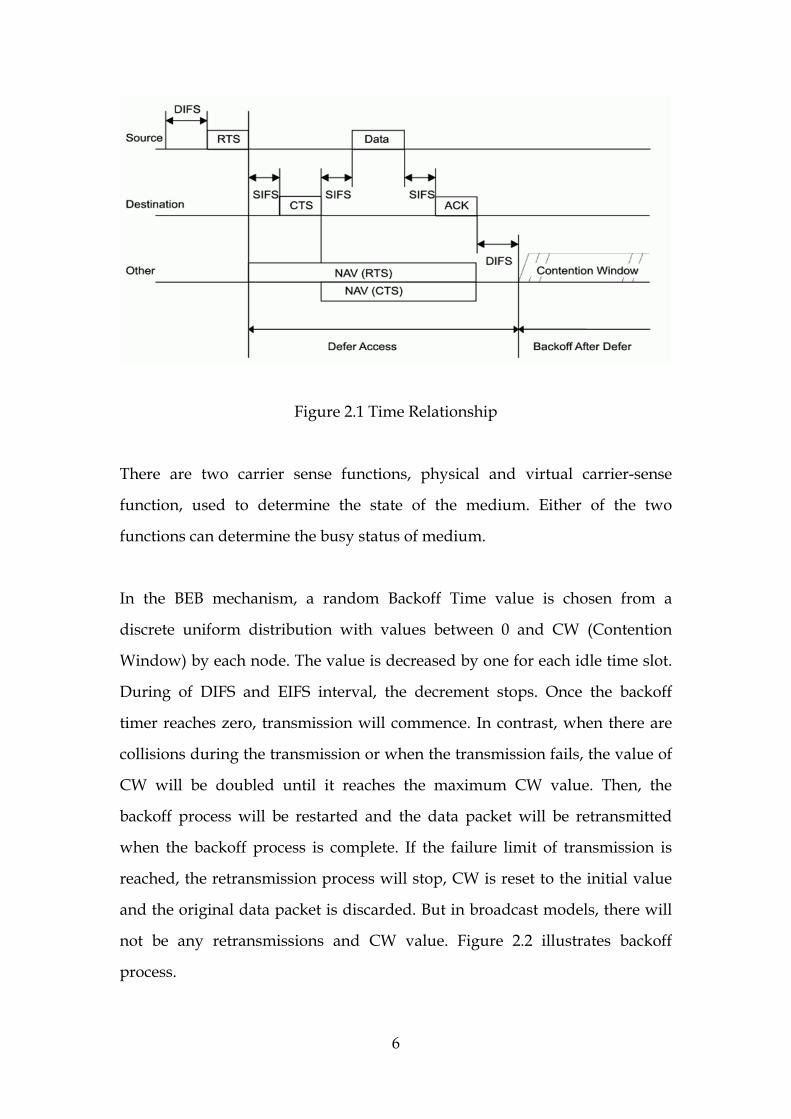
Figure 2.1 Time Relationship
There are two carrier sense functions, physical and virtual carrier-sense
function, used to determine the state of the medium. Either of the two
functions can determine the busy status of medium.
In the BEB mechanism, a random Backoff Time value is chosen from a
discrete uniform distribution with values between 0 and CW (Contention
Window) by each node. The value is decreased by one for each idle time slot.
During of DIFS and EIFS interval, the decrement stops. Once the backoff
timer reaches zero, transmission will commence. In contrast, when there are
collisions during the transmission or when the transmission fails, the value of
CW will be doubled until it reaches the maximum CW value. Then, the
backoff process will be restarted and the data packet will be retransmitted
when the backoff process is complete. If the failure limit of transmission is
reached, the retransmission process will stop, CW is reset to the initial value
and the original data packet is discarded. But in broadcast models, there will
not be any retransmissions and CW value. Figure 2.2 illustrates backoff
process.
6

Figure 2.2 Backoff Process
2.2 MANETs
Mobile Ad-hoc networks (MANETs) refer to self-organizing wireless
networks consisting of mobile nodes and supporting no fixed infrastructure.
The power limitations depress the range of radio transmission. To relay the
message throughout the whole network, each node in MANETs acts as a
router. Consequently, MANETs must be a distributed multi-hop network
with a time-varying topology.
Owing to self-organizing, MANETs is fittest to be deployed in
infrastructure-free environments, such as emergency rescue, military, airports,
sports stadiums, campus, disaster management as well as sensor network.
Based on such a broad application, the research and deployment of MANETs
must increasingly prevail.
7

2.3 VANETs
With the development of Intelligent Transportation System (ITS), Vehicular
Ad-hoc Networks (VANETs) become an emerging research area. As a specific
type of MANETs, VANETs have some similar characteristics to MANETs, e.g.
short radio transmission range, low bandwidth, omnidirectional broadcast
and limited storage capacity [10][22].
In addition to these similarities, the communication in VANETs meets some
particular challenging characteristics:
1) Rapid topology changes;
2) Frequent network partition;
3) Small effective network diameter;
4) Limited redundancy in time and in function.
5) Position predictability
6) Relatively sufficient power
Position predictability and relatively sufficient power may be utilized to give
support to inter-vehicle and vehicle-to-roadside communication, while rapid
topology changes, frequent network partition, small effective network
diameter and limited redundancy in time and in function aggravate the
difficulties to communication in VANETs.
8

In VANETs scenarios there are three most crucial challenges playing a vital
role to achieve stable and effective communication [2] that are
1) How to efficiently utilize limited bandwidth,
2) How to maintain the dynamically fragmented topology
3) How to achieve low-latency in delivering real-time information in
various situations.
2.4 State of the Art
On top of the aforementioned salient features and challenges on
communication in VANETs, a large number of research works have been
performed in various architectural layers in order to better fulfill the demands
of the communication in VANETs
At the routing layer, MANET research has focused on the development of
various routing protocols, analysis of these approaches under various
mobility models, and attempts to manage mobility-related routing issues [3].
In MAC layer, there are a large number of researches collision decision,
multiple channels, energy efficiency, directional antennas utilization and QoS
scheme.
Additionally, many other researches are done in physical layer for improving
bandwidth efficiency.
We will describe some of these related works in the next chapter.
9
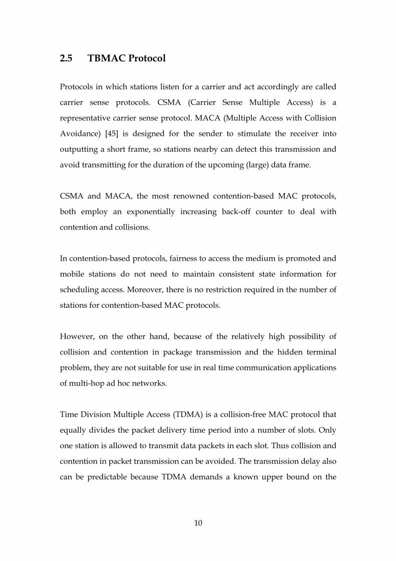
2.5 TBMAC Protocol Protocols in which stations listen for a carrier and act accordingly are called
carrier sense protocols. CSMA (Carrier Sense Multiple Access) is a
representative carrier sense protocol. MACA (Multiple Access with Collision
Avoidance) [45] is designed for the sender to stimulate the receiver into
outputting a short frame, so stations nearby can detect this transmission and
avoid transmitting for the duration of the upcoming (large) data frame.
CSMA and MACA, the most renowned contention-based MAC protocols,
both employ an exponentially increasing back-off counter to deal with
contention and collisions.
In contention-based protocols, fairness to access the medium is promoted and
mobile stations do not need to maintain consistent state information for
scheduling access. Moreover, there is no restriction required in the number of
stations for contention-based MAC protocols.
However, on the other hand, because of the relatively high possibility of
collision and contention in package transmission and the hidden terminal
problem, they are not suitable for use in real time communication applications
of multi-hop ad hoc networks.
Time Division Multiple Access (TDMA) is a collision-free MAC protocol that
equally divides the packet delivery time period into a number of slots. Only
one station is allowed to transmit data packets in each slot. Thus collision and
contention in packet transmission can be avoided. The transmission delay also
can be predictable because TDMA demands a known upper bound on the
10
number of stations in the network [28].
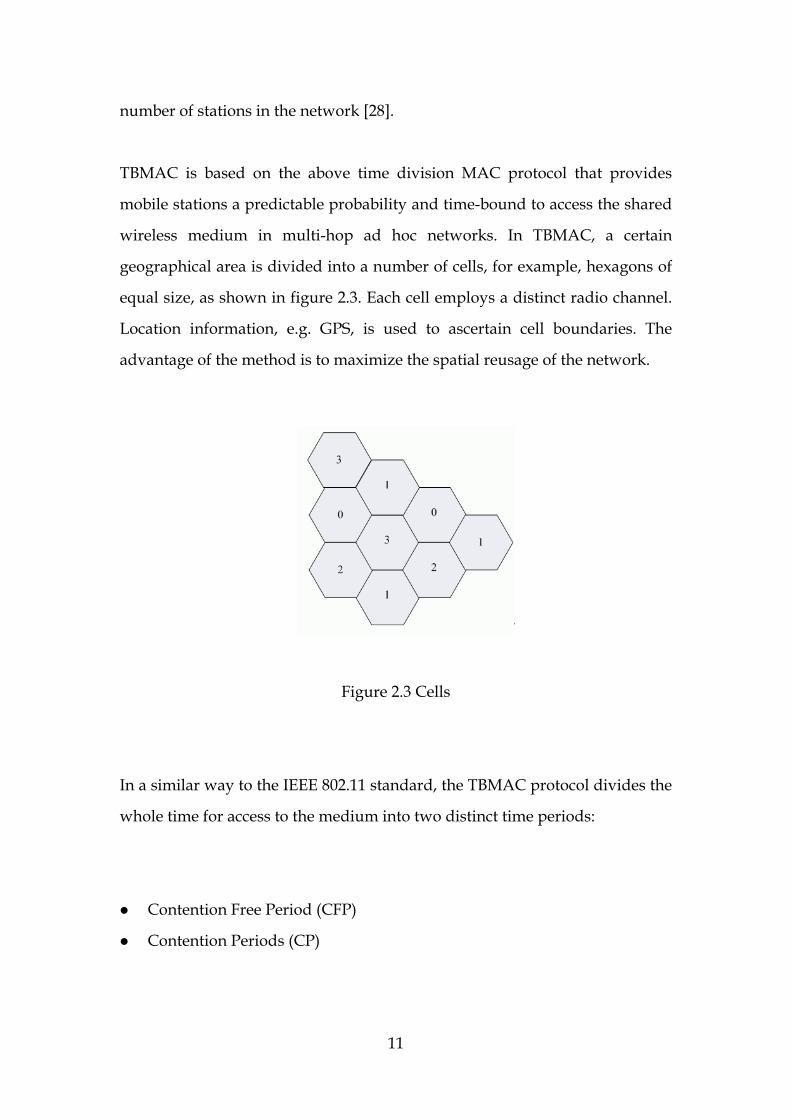
TBMAC is based on the above time division MAC protocol that provides
mobile stations a predictable probability and time-bound to access the shared
wireless medium in multi-hop ad hoc networks. In TBMAC, a certain
geographical area is divided into a number of cells, for example, hexagons of
equal size, as shown in figure 2.3. Each cell employs a distinct radio channel.
Location information, e.g. GPS, is used to ascertain cell boundaries. The
advantage of the method is to maximize the spatial reusage of the network.
Figure 2.3 Cells
In a similar way to the IEEE 802.11 standard, the TBMAC protocol divides the
whole time for access to the medium into two distinct time periods:
Contention Free Period (CFP)
Contention Periods (CP)
11

Mobile stations, which have no allocated CFP slots, contend and negotiate an
agreement on slot allocation in the CP and transmit data packets using the
allocated slots in the CFP. The CFP and CP constitute a TBMAC cycle. In a
TBMAC cycle, medium access in the CFP is similar to TDMA, while in the CP
it is similar to CSMA.
Unlike the PCF (Point Coordination Function) of the IEEE 802.11 standard,
the TBMAC protocol is not dependent on a particular point coordinator. To
ensure every station in a TBMAC cell comes to a consistent view of CFP slot
assignments, a lightweight synchronous atomic broadcast protocol is
exploited.
The TBMAC protocol uses two data structures, Slot Owners and Slot Bitmap.
Slot Owners stores mobile stations addresses and the corresponding allocated
CFP slots. Slot Bitmap uses two bits to represent the four possible states for
each slot: Owner, Other, Collision, Available. The Slot Bitmap, together with
source and destination, current slot number, message type, protocol
extensions and additional information, makes up the CFP header which is
included in the packet a mobile host sends in its CFP slot.
CFP slot management is composed of three parts:
Allocating a Slot
Deallocating a Slot
Inter-Cell Communication
12

Clock synchronisation is necessary for the TBMAC protocol to achieve slot
management. GPS facilitates to establish clock synchronisation of all mobile
stations in the network with microsecond-level precision.
The TBMAC protocol handles slot allocation in these potential scenarios as
follows:
One station enters or powers on in an active cell.
Two or more stations attempt to join an active cell at the same time.
One station enters or powers on in an empty cell.
Two or more stations attempt to join a cell nearly simultaneously.
Roughly, when a joining station is in need of slot allocation, it will monitor
the current state of the cell, then floods requests and negotiates an agreement
on slot allocation in the CFP. On the other hand, a set of atomic broadcast
metrics is utilized to deal with Slot Deallocation in the TBAMC protocol.
If there is a demand for inter-cell communication between two mobile stations
in adjoining cells, two particular inter-cell CFP slots will be allocated to the
two cells respectively. In a new version of TBMAC protocol, an Inter-cell
Communication Period (ICP) is proposed especially for message exchange
between cells.
Apart from the CFP and the CP, the new scheme of TBMAC assigns a time
period especially for inter-cell message exchange. Once a mobile node
attempts to send packets to another node in adjoining cell, it issues a request.
13
Then the node can carry out transmission on condition that the desired ICP
time slots are assigned to it. In this case, a TBMAC round comprises One CFP,
one CP and one ICP. To avoid potential collisions in the ICP, a mechanism
needs to be exploited to elect a gateway node to preside over the
communication with certain nodes.
14
Chapter 3
Related Works
In this chapter we describe some related works treating of layered
communication protocols, MANETs/VANETs simulations as well as traffic
and vehicular mobility simulation.
3.1 Physical Protocol
The Physical protocol is the lowest layer in a network stack. Nature imposes
two fundamental limits on all channels, and these determine their bandwidth.
These limits are the Nyquist limit, which deals with noiseless channels, and
the Shannon limit, that deals with noisy channels [47].
The Physical layer offers services as follows: carrier sensing, Clear Channel
Assessment (CCA); sending and receiving packets; received energy detection
on received packets; changing channels on physical layers that support
multiple channels and changing the state of the transceiver [50].
To meet the demand of bandwidth, some researches are done in physical
layer. Different frequency bands could be devoted to the different types of
15

messages, with varying transmission powers for each. For example, in [8] the
authors use a combination of low-frequency long-range infrastructure-based
communications and high-frequency vehicle–to-vehicle communication in
order to accommodate the varying delivery requirements for each message
type.
FCC ruling defines DSRC have six service channels and one control channel.
The control channel is to be regularly monitored by all vehicles. Safety
message is denoted to highest priority. [3]
In mobile Ad Hoc network, there are two kinds of nodes – exposed nodes
which are within the interference range of each other, and hidden nodes
which are out of interference range. The number of exposed nodes impacts
network throughput. We can increase the network throughput not only by
incrementing the number of nodes, but also enlarging the network size while
keeping traffic load constant [1].
However, the number of exposed nodes is related with radio range. Since the
interference radius is proportional to the radio range, increasing the radio
range to increase link stability, path life, or network connectivity will decrease
the network throughput. On the other hand, directional antennae could be
used to reduce the interference range. In this way, a transmission interferes
only with nodes in the direction of the transmission. However, directional
antennas increase the number of hidden nodes and have an adverse affect on
intrusion-detection systems. [9]
16

3.2 MAC Protocol
The MAC layer is the bottom part of the data link layer. The MAC layer
coordinates access to the communication medium by defining a set of rules
that allow fair and efficient sharing of common resource among multiple
users.
Characterized by the mobile nodes without centralized control in VANETs,
dynamically allocating slots, codes and channels is needed. VANETs are
multi-hop networks, MAC protocols of VANETs should coordinate the
channel access among these multiple nodes so as to utilize medium access
adequately.
Due to share medium access, simultaneous transmissions by two or more
nodes in a certain range cause signals collide and interfere with each other. In
another case, terrain condition and movement of mobile nodes affect signal
strength available to receiver. More hidden nodes will lead to more
retransmission and reservation packets so that they will interfere with other
ongoing transmission and cause collision.
Selecting an optimal radio transmission range is a tradeoff between maximize
the transmission channel reutilization and multi-hop forwarding, thus
affecting the aggregate throughput in ad hoc networks.
17
However, the effective transmission range depends on the number of nodes
in a certain area and their location and moving speed. Wireless channels are
time-varying and location dependent, data transmission rate should be
adaptive in VANETs.
Traditional MAC protocols such as TDMA, FDMA and CDMA are not
suitable in vehicular scenarios [3]. RTS/CTS scheme, such as MACA,
MACAW and FAMA is theoretically unsuited for broadcast. In MAC layer,
the most important thing is to organize the access to medium, or say
congestion control. In normal way, time slot and spectrum could be reserved.
For example, R-ALOHA is a famous slot-reservation MAC protocol,
discussed in [18]. The wireless token ring protocol (WTRP) is also a medium
access control protocol for wireless networks. WTRP guarantees quality of
service (QoS) in terms of bounded latency and reserved bandwidth, which are
critical in many real-time applications [19]. The optimum transmission
probability at MAC layer for each message is then identified to reduce the
packet collision probability. In [2], the writer proposes a Vehicular Collision
Warning Communication (VCWC) protocol that defines congestion control
policies so that a low message delivery delay can be achieved and a large
number of co-existing abnormal vehicles can be supported.
In the end of this section, we provide a structural illustration, shown as Figure
3.1, to demonstrate the classification of various MAC protocols [32].
18
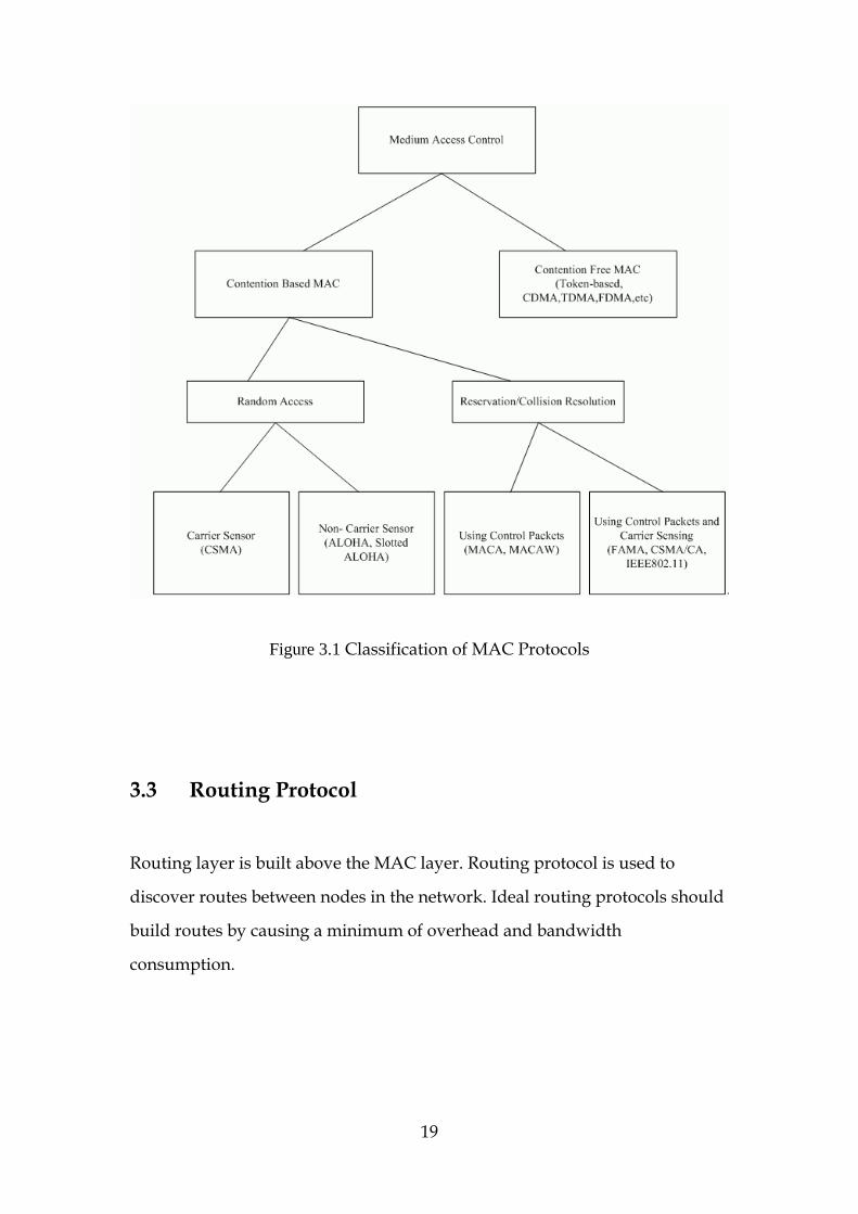
Figure 3.1 Classification of MAC Protocols
3.3 Routing Protocol
Routing layer is built above the MAC layer. Routing protocol is used to
discover routes between nodes in the network. Ideal routing protocols should
build routes by causing a minimum of overhead and bandwidth
consumption.
19
There are two widely used types of protocols in network routing: table-driven
protocols and source-driven protocols. Table-driven protocols use proactive
methods to maintain network topology.
3.3.1 Table-driven Routing Protocol
Table-driven routing protocols attempt to maintain consistent, up-to-date
routing information by broadcasting transmission that requires each node to
maintain one or more tables to store routing information.
Once there are changes in network topology, propagating update information
throughout the whole network has to be performed in order to maintain a
consistent network view. For instance, the Destination Sequenced Distance
Vector Routing protocol (DSDV) described is a famous table-driven algorithm
based on the classical Bellman-Ford routing mechanism. The Cluster-head
Gateway Switch Routing (CGSR) protocol defines several heuristic routing
schemes in a clustered multi-hop mobile wireless network. The Wireless
Routing Protocol (WRP) is another table-based protocol with the goal of
keeping routing information consistent among all nodes in the network.
Each node in the network is responsible for maintaining four tables: distance
table, routing table link-cost table, message retransmission list (MRL) table.
Optimized Link State Routing Protocol (OLSR) is also a kind of proactive
protocol. This algorithm floods broadcast message just through the nodes
selected by Multipoint Relays (MPRs)
20
3.3.2 Source-driven Routing Protocol
Different from table-driven routing, source-driven routing protocols, also
called on-demand routing, use a reactive way to find a route if it is desired by
source node.
The Ad Hoc On-Demand Distance Vector (AODV) routing protocol [52]
develops on top of DSDV algorithm previously. Basically, it minimizes the
number of required broadcasts by creating routes on a demand basis, as
opposed to maintaining a complete list of routes as in the DSDV algorithm
[53]. AODV broadcasts a route request (RREQ) packet from the initiator and
then the requests are forwarded until the destination is found. AODV utilizes
destination sequence numbers to ensure all routes are loop-free and contain
the most recent route information. The Dynamic Source Routing (DSR)
protocol provides a mechanism to make each node maintain route caches
which contain newly updated information. The Temporally Ordered Routing
Algorithm (TORA) is a highly adaptive loop-free distributed routing
algorithm based on the concept of link reversal. TORA is proposed to operate
in a highly dynamic mobile networking environment. The key design concept
of TORA is the localization of control messages to a very small set of nodes
near the occurrence of a topological change. The Associativity-Based Routing
(ABR) protocol defines a routing metric named as degree of association
stability. That is free from loops, deadlock, and packet duplicates. Signal
Stability-Based Adaptive Routing protocol (SSR) employs route selection
criteria to choose the routes that have “stronger” connectivity. SSR can be
divided into two cooperative protocols: the Dynamic Routing Protocol (DRP)
and the Static Routing Protocol (SRP).
21
In [4], the authors devised a model for discovery of spatio-temporal resources
in an infrastructure-less environment, in which the database is distributed
among the moving objects. In this model, two vehicles exchange their local
databases when their distance is smaller than the wireless transmission range.
Also [5] proposes 2 new flooding strategies based on an adaptive algorithm
VON. 1-hop which enhances traditional source routing for low mobility
nodes, reacting to VON efficiency decay and answer path routing failure. On
the other hand, 2.5-hop also reacts to VON efficiency decay and answers path
routing failure, but presents lower successful rates and is less redundant.
3.3.3 Location-driven Routing Protocol
In recent years, a number of location-based protocols are emerging. With the
development of location dependent service such as Global Position System
(GPS) and Adaptive Cruise Control (ACC), a lot of work has extended
location-based forwarding strategies, there are several routing-related
research efforts: location Service, recovery strategies, vehicle movement
patterns, digital maps and navigation systems [16].
In [6], the author described and analyzed a vehicle-vehicle Location-Based
Broadcast (LBB) communication protocol which is designed to meet the
application of DSRC. Cluster-Based Location Routing (CBLR) protocol,
somewhat reactive and distributed algorithm based on location of the nodes
is presented in [11] to Inter-vehicular and vehicle-to-roadside
communications. Using location-based routing, messages will likely be
delivered to vehicles in a zone of relevance for a given message [15].
22

In VANETs, limited resource (e.g. bandwidth) is obvious challenge.
Comparing with the other routing protocols, reactive protocols, in general, are
expensive in time consuming. Moreover, the incremental transmission
volume always leads to collision in medium access and communication
latency.
In the other hand, highly mobile nodes cause rapid changes in link
connectivity (e.g. link failure and topology changing) which causes many
paths to disconnect before they can be utilized. Thus preactive routing
protocols normally find routes before sending messages, they are not likely to
provide robust enough support to routing in VANETs.
However, location-based routing still does not address the frequent
fragmentation of the network. For this, epidemic routing protocols and hybrid
communication strategies are emerging. Epidemic routing protocols require
the prioritization of messages in the transmission queue; this prioritization
should reflect the time- and distance-varying importance of the messages. [4],
[9], [17]
3.4 Simulation
A simulation is a system that takes a simulating experiment description to
realize the experiment by running episodes and executing models). As a
result, a simulation produces data or generates scenarios to reflect the
behaviour of expected object in the real world.
The development of simulation is a complex work. Thus, some dedicated
23
simulation languages are created to simplify simulation development. But
these languages are domain-specific and thus have to suffer from
specialization. Nowadays, more and more simulations are developed by
generic programming language.
3.4.1 MANETs / VANETs Simulation
In this section, we sketch some famous MANETs/VANETs simulation.
3.4.1.1 Ns-2
Ns-2 [27] is a discrete event networks simulator written in a combination of
C++ and OTcl, a Tcl script language with object-oriented extensions
developed at MIT. Now, Ns-2 is the most widely used network simulator. It is
originally designed to simulate wireless LAN protocols. With unremitting
update, NS2 features a comprehensive model for simulating multi-hop
wireless networks nowadays. It can support TDMA MAC protocol.
3.4.1.2 GloMoSim / QualNet
GloMoSim [26] is a simulator designed for mobile wireless networks. It is
written in parsec, a variant of C with parallel programming extensions.
Further development of GloMoSim has been commercialized into the QualNet
product (http://www.scalable-networks.com/) since year 2000. GloMoSim
can support mobile wireless routing protocols, CSMA MAC protocols and
UDP and TCP communication. GloMoSim is also adept at simulating of
mobile IP networks.
24

3.4.1.3 TOSSIM / TOSSF
TOSSIM [54] and TOSSF [55] are both simulators built on TinyOS. [11]. In
particular, they are developed purposely to simulate the Berkeley MICA Mote
hardware platform. They also can simulate any TinyOS applications. One
flaw of TOSSIM is lack of a radio model. TOSSF tackles that limitation of
TOSIM but it is not as accurate as TOSIM. They are very useful for debugging
applications.
3.4.1.4 SWANS / JiST
Different from above simulators, SWANS / JiST uses Java, a standard
object-oriented language, to develop a new Java-based simulation framework.
JiST is a discrete event simulation engine that features high throughput and
automatic porting of application code to run in simulation time. SWANS is a
scalable wireless network simulator built upon the JiST platform. SWANS is
an application of JiST and create a simulation library.
Apart from the simulators outlined above, there are also some famous and
widely used MANETs/VANETs simulators. MATLAB, CSIM, OPNET and
SHIFT[20]are the delegates among them.
3.4.2 Traffic Simulation
Besides network simulations, a well-designed traffic simulation is also
essential to successfully simulate VANETs applications.
A few projects exist treating of traffic simulation. CORSIM [56] is one of the
most widely used microscopic vehicle traffic simulations. As a microscopic
25

conceptual simulation, CORSIM traces and represent individual action of
each vehicle [13]. Bonn-Motion [57] can generate simple vehicle movement
patterns that are used as trace files in network simulators. Vissim [58]
provides an implementation to approximate urban vehicle movement using a
microscopic simulation approach. It is developed by Java language. SUMO
[59] is designed to provide a common platform for testing and comparing
models of vehicle behaviour, traffic light optimization, routing etc. it is
written by usage of the standard C++. SUMO exploits microscopic,
space-continuous and time-discrete car-following model to implement vehicle
movements. STRAW [60] is built upon JiST/SWANS network simulation. It
provide a vehicular mobility model by usage of map data for real US cities
and limit their mobility according to vehicular congestion and simplified
traffic control mechanisms.
26
Chapter 4
DESIGN After covering much of the background research, we have already analyzed
and compared various existing communication protocols and a variety of
simulation works. From this chapter we start to develop a VANET
environment simulation and then build a TBMAC protocol simulation on top
of the implemented VANET scenario. This chapter aims to describe the design
architecture as well as to provide the details of each architectural component.
We also compare and contrast diverse simulation approaches and then pick
up the appropriate approaches. Moreover, we shall exhibit the corresponding
design issues behind the approach selection.
4.1 Introduction Performance evaluation is a crucial part of designing and validating new
protocols in the computer and communication fields. In [35] the authors state
that a realistic mobility model in an appropriate level of detail determines the
accuracy of network simulation results. For that reason, in this project the
most important challenge is to create a traffic simulation that accounts for
individual vehicular motion and the circumstance of radio transmission cell
so as to perform the TBMAC protocol in a simulated VANET environment.
27
As described in Chapter 3, TBMAC is a MAC protocol specially designed to
provide predictable access to wireless communication medium. In order to
evaluate the TBMAC protocol as well as other high layer protocols (e.g.
routing protocol) in further steps, this project intends to set up a simulation
environment consisting of two components, one is a vehicular mobility model
for simulating the movement of vehicles, the state of roadways and the
cellular structure built upon roadside base stations. The other is a TBMAC
Application Programming Interface (API) that accounts for the manner in
which the messages are exchanged.
4.2 Requirements Specification
A requirement is a statement that identifies a capability, characteristic or
quality factor of a system in order for it to have value and utility to design a
system. Requirements specification provides a range of underlying demands
for all of the following development work.
4.2.1 Realistic Vehicular Mobility Model
The mobility model of vehicular nodes is one of the most significant factors
that impact the results of VANETs evaluation by making use of this
simulation. Thus we should try to make the motion of simulated vehicles
similar to the way of vehicles perform in the real world. A realistic mobility
model facilitates to produce accurate results reflecting the practical
performance of a VANET.
28

4.2.2 Individual Behaviour
Different from some famous simulators which are designed to provide
large-scale transportation simulation environments to test and evaluate
macroscopical traffic phenomena such as the change of traffic flow and the
position where traffic jams easily occur. The primary objective of this
simulation is to perform and evaluate a new MAC protocol. Therefore, the
simulation focuses on the fashion of message exchanging and the
management of simulation time. To achieve that aim, we should pay a detail
attention to the behaviour of individual vehicle in a small-scale traffic
scenario. The vehicular behaviour contains not only the way of movement but
also the manner of sending and receiving messages.
4.2.3 Visualisation and Animated Graphics
The simulation scenarios are supposed to be shown on-screen as 2D graphics
including road-like background, dividing lines on the road, and a shape of
sorts to characterize base stations and transmission cells. However, vehicles in
simulation ought to be represented as animated images with a range of
speeds. Visualisation and animation will give an intuitive presentation to end
users.
In sum, simulation scenarios of this project will be initialized and manifested
through a user-friendly graphical user interface (GUI). In addition to show
the running of the expected simulation, the GUI can also be used to view and
edit the simulation parameters of a given scenario through the use of a series
of defined variables and a configuration file.
29

4.2.4 Modularization and Aggregation Method
Even though the primary version of this simulation is designed only to
perform the TBMAC protocol, we should take modular aggregation concept
into consideration in the very beginning of the design phase.
As known to all, one of the most essential concepts of the computer networks
is network layering stack that allows developing various layer protocols of
networks in hierarchical levels [47].
In the future work, the simulation and implementation on physical layer, data
link and network layer must be developed. These models of different layers
have to coexist. Since in multi layer simulation scenarios, the parameters of
some models may influence the other hierarchical levels.
From integrated view of cross layer network simulation, for the evaluation of
routing algorithms MAC and network layers have to be simultaneously
simulated. For transport layer MAC layer has to be modelled. Those
cross-layer simulations happen to be difficult to operate, but they are
promising methods. [46]
4.3 Choices of Simulation Modes
4.3.1 Rationale of Simulation Study
Simulation is a technique of imitating the behaviour of some real-life system
by means of an analogous model to gain information and further facilitate
30

learning about the system. In [34], the authors outline three conventional
methods that are experimental model, analytical model and simulation model.
With the assist of the three models, we can understand a realistic system.
Figure 4.1 illustrates the relationship of experimental model, analytical model
and simulation model and how they lead to learn the system in the real
world.
Normally we use experimental studies restricted to some partial fields in a
whole system. While analytical studies can only deal with large-scale systems
of reasonable complexity. Simulation studies are most suitable applied in
such new generations of computing networks and telecommunication
systems as mobile ad hoc networks.
Figure 4.1 Ways to Learn a Realistic System
31

4.3.2 Discrete Event Simulation
According to the particular logical facets that a system intends to represent,
simulation models can artificially be categorized as continuous simulation
models and discrete simulation models [36].
In continuous simulations the state of the system changes continuously with
time elapsing, as illustrated in Figure 4.2. The state change of a continuous
system can be described by some known differential equations.
Figure 4.2 Continuous Simulation Model
On the other hand, the state of a discrete system changes just only at a
discrete set of selected time points (or say moments) in a determined period
[49], as shown in Figure 4.3. For instance, in a traffic modeling scenario,
vehicle arrival at a certain point that occurs at distinct points in a scheduled
period can be considered as an event. A unit in a traffic environment, e.g. a car,
32
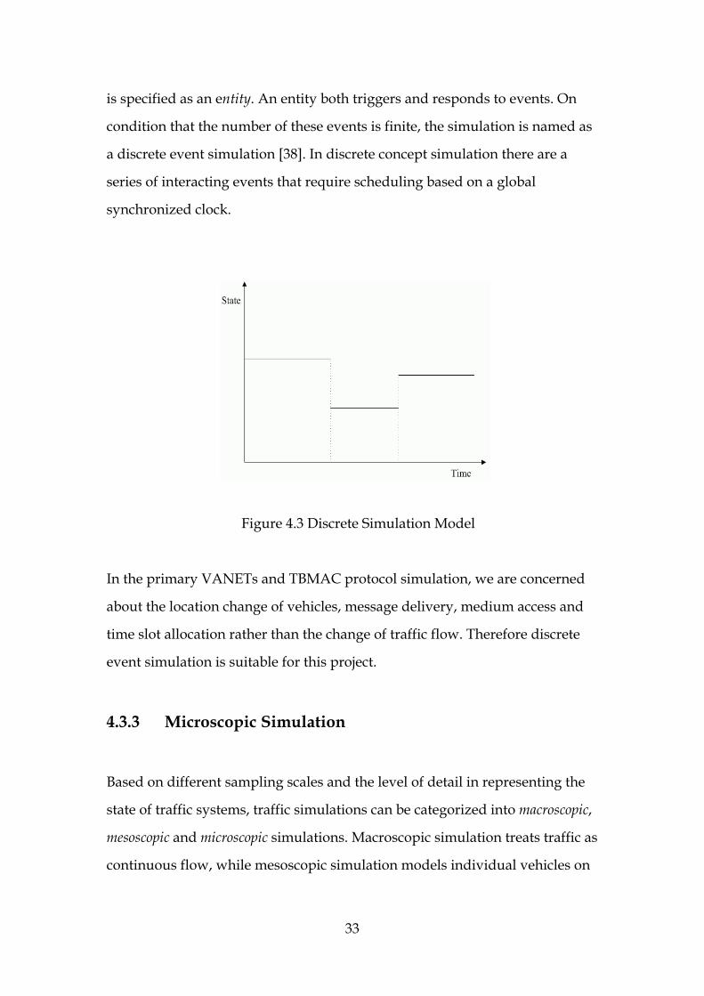
is specified as an entity. An entity both triggers and responds to events. On
condition that the number of these events is finite, the simulation is named as
a discrete event simulation [38]. In discrete concept simulation there are a
series of interacting events that require scheduling based on a global
synchronized clock.
Figure 4.3 Discrete Simulation Model
In the primary VANETs and TBMAC protocol simulation, we are concerned
about the location change of vehicles, message delivery, medium access and
time slot allocation rather than the change of traffic flow. Therefore discrete
event simulation is suitable for this project.
4.3.3 Microscopic Simulation
Based on different sampling scales and the level of detail in representing the
state of traffic systems, traffic simulations can be categorized into macroscopic,
mesoscopic and microscopic simulations. Macroscopic simulation treats traffic as
continuous flow, while mesoscopic simulation models individual vehicles on
33

an aggregate level and pays attention to some integral factors, i.e. traffic
throughput [24].
In contrast to macroscopic and mesoscopic simulation, microscopic
simulation concentrates on capturing the behaviour of vehicles in detail [42].
Accordingly, macroscopic and mesoscopic simulation are both weak to
instantaneously respond to changes in modeling traffic system, whereas
microscopic simulation models can better simulate the spatio-temporal
changes of vehicles individually [38]. Furthermore, the rapid advancement of
computer processors helps address the suspicion on the consumption of
computational capabilities in microscopic simulation.
In this dissertation we are concerned about the behaviour of individual
vehicle in motion and communication in pairs. Obviously, microscopic
simulation concept fits our expected simulation very well.
4.4 Object Oriented Simulation Tool
Object oriented concept is increasingly impacting the way in which software
developers think about software. Object oriented principles arose from
SIMULA67, researching simulation-based languages. The power of object
oriented techniques lies in the ability to produce ‘modular’ code (named as
classes) that can be easily modified and reused [40]. The intention behind
Object Oriented Programming (OOP) concept is that the objects in object
oriented software represent the similar behaviour and relationship to the
entities in the real world. Therefore object oriented technique is inherently
suitable for simulation development.
34

Object Oriented Programming differs from traditional program development,
such as functional programming or procedural programming, in the way of
structuring the data and the code of software. Object Oriented Programming
simplifies software complexity by means of encapsulating functions and
procedures into an object. Accordingly, this project employed Java
programming language to develop TBMAC simulation. As a full object
oriented language, Java language has a number of merits benefiting
simulation development, such as hierarchy, inheritance, class structure,
modularity and polymorphism. Moreover, there are some subtle but
important particulars that Java language provides to avail building
simulation, for instance, automatic garbage collection, type-safety and
reflection [41]. In virtue of Java, we segment the simulation into a set of
non-overlapping entities.
Java also provides the excellent support for programming Graphical User
Interface (GUI) as well as 2D animated graphics. Furthermore, in the future
work, not only MAC layer protocol but also some high layer communication
protocol and applications should be simulated and implemented on the
simulation.
4.5 VANETs Simulation
4.5.1 Vehicle Mobility
To simulate VANETs, one of the key factors is the vehicle mobility model that
not only determines the location of vehicles but also influences the network
topology, network connectivity and the access to medium [23].
35

4.5.1.1 Vehicle velocity
The speed of a vehicle determines the location change of the vehicle in a
certain time. The various speeds of vehicles cause the change of network
topology. In this project we set the bound of vehicle speed from 0 to 100
km/h.
4.5.1.2 Acceleration and Deceleration
In the real world, there are few scenarios in which a vehicle keeps the same
speed for a long time. So we introduce the concept of acceleration and
deceleration into this work.
4.5.1.3 Interdependent movement
It is well known that the movement of vehicles is constrained not only by the
shape of the road but also by neighbouring vehicles. The speed limitation of a
vehicle should be considered as a mixture of the highest speed bound and the
front vehicle speed.
4.5.1.4 Simplified modeling factors
Apart from these highlighted specifics described above, we make some
unconcerned factors straightforward so as to simplify the complexity of the
whole system. For example, some vehicle motions such as lane change and
overtaking other vehicles.
36

4.5.2 Roadway Layout
As mentioned above, the behaviour of nearby vehicles and the speed
limitation impact vehicle motion. Moreover, vehicle motion must be
constrained to roads. The boundaries of roadways confine the movement of
vehicles to a predefined route. Due to the constrained route, the network
topology and the routing pattern can be better predicted. The roadway is
designed as a two-lane street, and each lane supports an opposite driving
direction. Because we mainly want to examine TBAMC slot management
influenced by the vehicle speed and location, we make a simplified
assumption that the roadways are straight, the terrain is tacit to be constantly
flat and the junction of roadway is ignored, as plotted in Figure 4.4.
Figure 4.4 Layout of Roadway
4.5.3 Roadside Base Station and Cell
VANETs combine vehicle-to-vehicle communication and roadside-to-vehicle
communication. Vehicle-to-vehicle and roadside-to-vehicle communication
37

relies on the infrastructure-less network structure. However, different from
other general MANETs, a roadside base station that plays a fixed node in
VANETs normally acts as a master, namely a coordinator, in the
infrastructure-less network structure. The range of radio transmission
determines the size of the area that a roadside base station covers.
Theoretically, a cell and all of its contiguous cells should be covered by the
radio transmission from the base station in itself. The cells could be shaped as
a cellular structure that is illustrated in Figure 4.5. Each cell contains one and
only one roadside base station. The number of vehicles is dynamic based on
the movement of vehicles.
Figure 4.5 Base Stations and Cells
4.5.4 Send and Receive Messages
Both vehicles and base stations are nodes in VANETs communicating with
each other by sending and receiving packets.
38

4.5.4.1 Intra-cell communication
According to the TBMAC protocol, access to the wireless medium for
intra-cell communication is divided into CFP and CP. The CFP and the CP are
also equally divided into a series of time slots. The periodicity of packet
transmission within a cell is defined within the CFP. Thus time slots in the
CFP are assigned to vehicles in order that each vehicle can send packets in a
dedicated and predictable duration. Moreover the possibility of collision can
be avoided to a large degree. Newly arriving mobile nodes in a cell negotiate
the allocation of CFP slots in the CP.
4.5.4.2 Inter-cell communication
If a vehicle attempts to send a message over cell boundaries, it will send the
message to the base station in the same cell. The base station, playing a role as
a gateway, relays the message to the base station in the destination cell. At last
the terminal vehicle gets the message from the base station of its own cell.
Furthermore, the new version of the TBMAC protocol assigns an Inter-cell
Communication Period (ICP) especially for inter-cell communication, as
illustrated in Figure 4.6. Base stations can employ the time slots in the ICP to
perform inter-cell communication.
Figure 4.6 TBMAC Round Structure
39
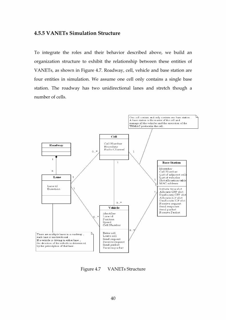
4.5.5 VANETs Simulation Structure
To integrate the roles and their behavior described above, we build an
organization structure to exhibit the relationship between these entities of
VANETs, as shown in Figure 4.7. Roadway, cell, vehicle and base station are
four entities in simulation. We assume one cell only contains a single base
station. The roadway has two unidirectional lanes and stretch though a
number of cells.
Figure 4.7 VANETs Structure
40

4.6 TBMAC Application Programming Interface
On top of the traffic simulation proposed above, we attempt to investigate the
impact of the TBMAC protocol performing on both the MAC layer and high
layers. Consequently, we can evaluate the performance of the TBMAC
protocol accurately. In network simulation the TBMAC protocol is
responsible to control the access to the medium, i.e. initiate a set of time slots
and manage slot allocation. One obvious advantage of this TBMAC approach
is to minimize the occurrences of collisions among mobile nodes in accessing
wireless channels.
However, how to perform slot management is decided by the layers above
the MAC layer, such as Quality of Service (QoS) layer, Routing layer and
Admission Control layer. For example, when a car comes into a new cell,
Admission Control layer will monitor this event and send a request to MAC
layer to ask for allocating CFP slots to the car. As for how many CFP slots
should be allocated to the car, that demand will be proposed by the QoS
layers.
To sum up, the ideal TBMAC protocol model should allow new models in
other layers to be aggregated on top of itself with ease. Therefore, it is
necessary for the TBAMC protocol to provide an application programming
interface (API) to facilitate the communication with other layers, as illustrated
in Figure 4.8.
41

Figure 4.8 TBMAC API
4.7 Scenarios and Use Cases
The base station and vehicles represent master slave behaviour [44] in the
communication in a cell. We designate the roadside base station as a
permanent master in its own cell and vehicles act as slaves. So, in this project
there are no empty cell scenarios. Every cell is always an active cell.
4.7.1 TBMAC Execution
The base station takes charge of almost all management tasks, e.g. clock
synchronisation, admission control, slot allocation maintenance and inter-cell
communication. We focus on the execution of the TBMAC protocol.
42

4.7.1.1 Clock synchronisation
First of all, we should set up a global time in the whole cells by a clock
synchronisation mechanism, for example Christian’s Method. As such, the
base station in each cell has a synchronous clock to initiate the TBMAC
protocol. For Clock synchronisation of all the nodes in a cell, we propose to
use master-slave global time method that has been used in several related
works.
4.7.1.2 Time slot scheduling
Firstly, a beforehand determined period of performing simulation is divided
into a sequence of TBMAC rounds. As discussed previously, the duration of
each TBMAC round is equal and a TBMAC round is also segmented into a
series of time slots with equal size. According to the definition of TBMAC
protocol, we specify these time slots into three types, Contention Free Period
(CFP), Contention Period (CP) and Inter-cell Communication Period (ICP).
However the size of time slot is related to the size of the packet to be sent.
Moreover, the maximum size of a packet is constrained by the bandwidth of
radio channel. According to the experiment carried out in [43], we define time
slot size is 50ms. Next, A TBMAC round is statically divided into twenty time
slots, ten for CFP, four for CP and six for ICP. Thus, a cycle of TBMAC costs
1000ms, as shown in Figure 4.9.
50ms
CFP ICPCP
1000ms
Figure 4.9 Slot Scheduling
43
In the future work, the division of TBMAC round and slot size could be
allowed being dynamic according to vehicle speed and QoS demand.
4.7.1.3 Slot management
When a base station of a cell gets a request for CFP allocation, it will check the
current state of CFP allocation and the list of vehicles in the cell. If it is a new
identifier of the vehicle, then base station will add the node identifier into the
list of vehicles. Then the base station assigns corresponding CFP time slots to
the vehicle. This message includes the MAC address of the base station and
the time stamp of the master clock. In the end the state of CFP allocation will
be updated. In the same way deallocating CFP slots are performed by base
station. ICP slots are separately plotted out for inter-cell packet transfer by the
communication between base stations.
4.7.2 Vehicle Behaviour
Vehicles act as mobile nodes with diverse speed in VANETs. When a vehicle
enters into a cell, it can sense the new cell and realize the change of position
by passing through the boundary of the cell. After monitoring a full CFP cycle,
the vehicle broadcasts the messages about itself, i.e. speed, identifier in the
following CP. If it needs to send packets, the vehicle can also send a slot
allocation request in the CP. Once the vehicle gets the CFP slots assigned by
base station, it can send data in the corresponding CFP time slots.
If a vehicle needs to send packets to a neighbouring cell, it still uses the CFP
slots to deliver the packets to its own base station. The base station will be
responsible to send the packets across cells in the ICP.
44

When a vehicle is going to leave a cell, it sends a request for CFP slot
deallocation to the base station.
We use Figure 4.10 to illustrate the scenario in which a vehicle performs
communication by following the TBAMC protocol.
Enter
Intra-cell communication
Inter-cell communication
Slot request
Listening
50ms
CFP ICPCP
Send requests for CFP/ICP
slot
Send Packets to the nodes in a
cell
Send Packets to the nodes in a adjacent cell
Figure 4.10 TBMAC Communication
45

4.7.3 Use Case
Based on the scenarios described above, we develop use cases to represent a
set of similar scenarios all with the same type of user. UML diagram here is
employed to show two actors: “Base station” and “Vehicle” and a number of
use cases. The use case diagram is illustrated in Figure 4.11.
Figure 4.11 Use Case
46
4.8 Summary
In this chapter we first outline the specification of requirements. We also
choose appropriate simulation approaches according to the expected
functionalities of the simulation. Next, the development tool of simulation is
compared and selected. Then, we discuss the main factors influencing the
design of VANETs and give an overview of VANET simulation architecture.
In the end, we design a scheme to simulate the TBMAC protocol performing
over VANETs simulation as well as establish an API to facilitate the
interaction of TBMAC layer and higher layers.
47
Chapter 5
Implementation
In this phase, we endeavor to implement the simulation by following design
principle provided in the design phase. This chapter outlines the
implementation of the design architecture presented in Chapter 5. First of all,
we describe development tools and value their avail. Next we identify and
decide on optional techniques for implementing each component of the
architecture. We also detail these choices and methods we made in the
process of implementation.
5.1 Introduction
This simulation is designed to be component based. We try to develop this
program incrementally. In that case, we ascertain that each implemented
components works correctly and achieves the expected independent
functionalities before we move on building the next components.
The components are organized in as follows: roadway, lane, vehicle, cell,
baseStation and tBMAC. Each component involves one or more classes
attempting to achieve a group of relative functionalities. We endeavor to
make each component variable levels of detail so as to enhance the
configurability of the simulation
48

To avoid the confusion from the denotation of component and class, we
define the name of component is low case italic type (e.g. vehicle), while class
is upper case italic type (e.g. Vehicle).
5.2 Development Tools
All code in this simulation will be written in Java programming language. We
use Java 1.5 version and employ Eclipse platform as Integrated Development
Environment (IDE). Graphics will be rendered by the use of Java Swing and
AWT graphics package. JUnit is used for unit testing.
We outline some of these tools and their value in simulation development.
• Swing and AWT
Friendly User Interface (UI) has been a basic requirement to
simulations nowadays. Java provides several powerful graphic packets
to facilitate the development of graphical user interface (GUI), such as
Abstract Window Toolkit (AWT), the Standard Widget Toolkit (SWT)
and Swing. Via GUI, users visually see the performance and results of
simulations. Furthermore users can make interactions with simulations,
for example setting and modifying parameters about simulation
ingredients.
Because AWT is thought to be function-limited but require less
memory, we will use it to do a portion of graphical works, for example
layout manager and event-handling.
49

Swing is a part of the Java Foundation Classes (JFC), a collection of
technologies that includes Swing, AWT, Java 2D, Java Drag and Drop,
etc. Swing is thought to provide a more well-designed and higher level
programming model. Most Java GUI programming in this simulation
will be executed by Swing.
• Threads
From a real-world traffic view, multiple entities take various actions
concurrently. Threads allow performing multiple tasks at the same
time. From a programming point of view, creating multiple threads is
equivalent to being able to invoke multiple methods at the same time.
Java Thread constructor with its comprehensive libraries offers a
vigorous support to concurrent execution. No matter in implementing
vehicular mobility model or in performing TBMAC communication
can Java Thread play a vital role.
• JUnit
From a software engineering point of view, testing is an essential work
in simulation development. For this project, we employ JUnit to do
unit-level testing automatically. JUnit is a framework for writing unit
tests that supports to incrementally develop the simulation. Unit
testing proves that the desired features have been achieved. Moreover,
it keeps the completed code stable and maintainable.
50

5.3 Components
5.3.1 Roadway
We apply Java Swing and AWT graphic packages to create the main window
and manifest roadway and roadside base station on the screen. We assume
that roadway could be single-lane or multiple-lane based on the configuration
of users.
private static final double LANE_WIDTH = 100; private static final int NUM_LANES = 4; private static final double ROADWAY_WIDTH = LANE_WIDTH * NUM_LANES;
More explicitly, there are some dividing lines on the roadway to separate
lanes. According to traffic road in the real world, we specify several sorts of
traffic dividing lines by the definition of a number of corresponding variable
parameters.
5.3.1.1 No-passing line
There is a no-passing line in the middle of roadway to separate two groups of
diverse directional lanes. The no-passing line might be double-yellow-line or
single–yellow-line according to various traffic laws.
private static final double LINE_SPACE = LINE_WIDTH / 3;
51

Figure 5.1 No-passing Line
5.3.1.2 Passing line
There are also passing lines to divide uniform directional lanes. The passing
line is drawn as a dash line.
private static final double DASH_LENGTH = LANE_WIDTH / 5; private static final double DASH_SPACE = DASH_LENGTH / 3;
public void paintPassingLine(double y) {
double x = ROADWAY_LEFT; Drawline dashline; while (x < ROADWAY_RIGHT) { dashline = new Drawline(x, y, DASH_LENGTH, LINE_WIDTH); dashline.setColor(Color.white); x = x + DASH_LENGTH + DASH_SPACE; } }
52

Through above steps, we can get a roadway graphic as demonstrated in
Figure 5.2.
Figure 5.2 Dash Passing Line
5.3.1.3 Base Station
Different from dynamic vehicular nodes, base stations is a group of static
images regularly distributing on the both sides of the roadway. It displays on
the screen based on the location of roadway illustrated as Figure 5.3.
Figure 5.3 Base Stations on the Roadside
53

5.3.2 Lane
Unlike component roadway mainly takes control of drawing background and
graphics on the screen, component lane is responsible to create moveable
vehicles passing through a particular lane. We use while loop inside run
method to aperiodically initiate a vehicle in left or right end of a lane.
On the other hand, the constructor of class Vehicle needs to get an empty lane
so as to appear a new vehicle on a multi-lane roadway.
ranlan = new Random(System.currentTimeMillis()); public Lane getRandomNextLane () {
if (laneLeftEnd.isEmpty ()) return null; Object[] list = laneLeftEnd.toArray (); int temp = ranlan.nextInt (laneLeftEnd.size ()); return (Lane)list[temp]; }
The component lane publics a series of variables, such as the speed limitation
of this lane, the starting point on the screen, exact position while running, that
are useful to component vehicle.
54

5.3.3 Vehicle
5.3.3.1 Dynamic object
In order to make vehicles dynamic, we build a DynamicObject class to
represent a general moveable object. In each discrete time point, the position
of the object should be updated so as to show it moving. We use positionTrans()
method to keep posted the position change of a vehicle. In the same way, we
use accelerate() and decelerate() method to update the velocity of the object.
5.3.3.2 Static specifics
We build a Vehicle class to represent each specific vehicle and a range of
distinct static parameters will be passed to Vehicle. Class Vehicle extends
DynamicObject. We define the method run() to start the Vehicle. In class Vehicle,
We create a number of parameters to indicate the position in which a vehicle
is situated, the speed with which the vehicle is moving, the image used to
manifest the vehicle and so on. These parameters will be provided to the
constructor of the vehicle. To sense which cell it is located, we also set the
boundary of cells as a parameter and present it to the constructor.
We use System.currentTimeMillis() to get the current time. Thus component
lane can record the time of each vehicle appears and disappears.
5.3.3.3 Vehicle generation
In simulation environment we should specify the time interval in which pairs
of vehicles appear on the screen. A parameter will be created to determine the
number of vehicles in a lane at the same time. On the other hand, it is should
be specified that how long on earth is the time interval after which a vehicle
55

appears at a particular lane. We set a random pause time within a
configurable range as the time interval.
5.3.3.4 Vehicle velocity and inter-vehicle distance
To avoid collision accidents (car crash is indeed a realistic traffic affair, but we
do not care about it in this simulation), vehicles should keep a proper safe
distance. There are several types of car-following models to determine the
distance [25],[48].
We use linear car-following model. When a vehicle is generated, it will get a
random initial speed. We temporarily set the speed ranging from 0.025 to
0.166 pixels/millisecond.
public class RandomSpeedGenerator { public double max; public double min; public RandomSpeedGenerator (double min, double max) {
this.min = min; this.max = max;
} public double nextValue() {
return min + Math.random() * (max - min); } public String toString() {
return "RandomSpeedGenerator ranges from " + min + " to " + max; }
56

For a driving vehicle A, if there is no preceding vehicle within a safe distance
of S meters, vehicle A will increase its speed by accelerate() method until
getting the speed limit. On the other hand, if there is a foregoing vehicle B
within the safe distance S meters, vehicle A will reduce its speed by
decelerate() method. But somewhat dissimilar to realistic situation, if vehicle
A approaches a frontal vehicle B within a risky distance R meters, vehicle A
will stop at once. We use a piece of pseudo code to represent this logic (x
stands for the distance between two vehicles);
function Speed_updating (speed V) {
if x>S ; {
accelerate(); }
else { if x<=S && x>R;{ decelerate();
}
else { V = 0; } } update Speed; }
5.3.3.5 Vehicle image
Vehicles get images according to the starting point they are placed, because a
vehicle in left or right direction requires different images. We build 12 images,
57

6 for right and 6 for left. There are bus, van, SUV, car, SRV and ambulance.
Component lane will help class Vehicle recognize diverse Vehicle Images and
keep the VehicleImage appearing on the tracks by use of an instance variable.
5.3.4 Cell
Cells exhibit cellular structures built upon the position of base stations. A Cell
accounts for the range of radio transmission disseminated from a base station.
We use the methods provided by Java Swing and AWT to draw polygons
representing the cells. We outline a small piece of code to interpret the
algorithm of hexagon.
public void DrawHex(Graphics g) { int i; Polygon cell = new Polygon(); for (i = 0; i < 6; i++)
{
(cell).addPoint( (int)(x + Global.r * Math.cos(i * Math.PI / 3)), (int)(y + Global.r * Math.sin(i * Math.PI / 3)));
} g.setColor(Color.gray); g.drawPolygon(cell); }
A cell with a unique identifier has knowledge about its boundaries. When a
vehicle “enters” in a cell, the vehicle should be aware of overlapping the
boundary of cell. We use the resume() and suspend() methods of Java’s class
58

Thread to implement the enter() method. The method suspend() temporarily
halts a thread; while resume() allows the thread to resume. Class Cell involves
the definition of overlap() method that makes a VehicleImage as a parameter
and returns a boolean value to Vehicle.
public boolean condition(VehicleImage) { return true;
}
Then class Vehicle passes vehicleid, laneid to Cell. Cell adds the vehicleid as index
word into a table which records the status of all the vehicles in the cell.
In the contrary, once vehicle leave a cell by touch the boundary of the cell in
the second time, the boolean value is changed and returned to class Vehicle
again.
5.3.5 Base Station
Base station acts as a master node in communication of vehicular networks. It
takes on the responsibility for most work of managing the TBMAC protocol.
We establish two components (baseStation and tBMAC) to implement the
simulation of the TBMAC protocol. We will detail the operation of baseStation
in implementing TBMAC execution in the next section, together with tBMAC.
Additionally, baseStation maintains two tables. One records the status of all
the vehicles in a cell and the other minutes time slot owners. As a node in
VANET, baseStation also need to invoke SendPacket() method and
ReceivePacket() method provided by component tBMAC to perform
communication.
59
5.3.6 TBMAC Processor
TBMAC processor component, named tBMAC, interacts with the traffic
simulation consisting of the five components as above, roadway, lane, vehicle,
cell and baseStation. We break down the execution of implementing
component tBMAC as follows.
5.3.6.1 Global time synchronizing
In simulated VANETs, we make a master-slave scheme. Base station, as the
master node in a cell, has responsibility to announce the standard time as well
as the knowledge on the message delay between two nodes. This global time
method has proved to be able to achieve the precision of 10 millisecond level
by some related work, such as Mica.
5.3.6.2 Time scheduling
In the beginning, class TimeScheduler calls InitiateSlot() method to break a
predefined cycle time into a number of time slots in equal size and categorize
them to three group, CFP, CP and ICP. To simplify this work in this thesis, we
define the cycle time is 1000ms, the size of time slot is 20ms. They could be
configurable in the UI panel in the future work.
In addition, we make a little change of TBMAC description about ICP for
speeding up the development. ICP time slot is set as global time slot which
can perform not only intra-cell communication but also inter-cell
communication, while CFP time slot is made as local time slot that only
perform intra-cell communication.
60

In the end, we join the above approaches and choices together. The TBMAC
cycle time is divided into CFP, ICP and CP. We create cfp(), icp() and cp()
methods to respectively execute intra-cell communication, inter-cell
communication as the manner discussed above.
public interface CycleTime { void cfp(); void icp() throws StopCycle; void cp(); }
5.3.6.3 Slot management
RequestSlotAllocation() method is invoked by Vehicle. Class Vehicle sets the
requests of vehicle identifier, expected accepter and real-time constraint as
parameters of RequestSlotAllocation(). This method is non-blocking and thus
the return value only identifies the success or failure status of submitting the
slot allocation request.
After receive the slot allocation request, class SlotManagement invokes
AllocateSlot() method which can be blocking. The return value is the slot
number assigned to the requesting vehicle. If this call is successful, slot owner
table will be renewed.
Similar to the process of slot allocation, vehicle executes slot deallocation to
use RequestSlotDeallocation() method which is non-blocking and return value
indicates the success or failure status of submitting the slot deallocation
request. If there is a request for deallocating time slot, class SlotManagement
invokes DellocateSlot() method which might be blocking. Slot owner table will
be renewed after successful call.
61

5.3.6.4 Packet exchange
As mentioned before, SendPacket() method and ReceivePacket() method are
implemented by component tBMAC to meet the requires of message exchange
from vehicle and baseStation.
Here we give a description of method SendPacket() for example.
SendPacket() calls the parameters of allocated time slot number as well as
message type and address. Packets can be sent only in the specific time slots.
SendPacket() is a non-blocking method. The return value from invocation of
SendPacket() implicates the success or failure of starting the packet
transmission process. We assume that value 0 will be returned if transmission
starts successfully. If a negative value is returned, transmission failure occurs.
In the case of failure, the method SendPacket() may block.
5.4 Summary
In this chapter, we discussed on the subject of how to implement the
components of VANETs simulation and TBMAC simulation in detail. The
interaction of these components is also explained. The component roadway,
lane, vehicle and cell achieve most of functionalities of traffic simulation.
Component baseStation relates the traffic simulation with TBMAC simulation.
Component tBMAC, together with baseStation and vehicle, performs
vehicle-to-vehicle communication and vehicle-to-roadside communication by
following the TBMAC protocol.
62

Chapter 6
Evaluation
This Chapter intends to test and investigate the performance of the simulation.
Based on the experiment, we attempt to evaluate the strengths and
weaknesses of this simulation.
6.1 Performance
The first step of evaluation is setting up a test platform which combines
hardware equipments and software system. Because this simulation is
designed for simulating small-scale traffic environments, we do not need a
powerful computing platform.
The performance measurements of the simulation were taken on two
computers. One is Dell Latitude D400 laptop computer with Mobile Intel
Pentium M 1300 MHz CPU, 1M On-Die Full-speed L2 Cache and 512M
DDR333 SDRAM. The other is HP VL400 Desktop computer with Intel
Pentium III 800EB CPU, 256K On-Die Full-speed L2 cache and 128M PC133
SDRAM. Dell Latitude D400 is running the Windows XP with SP2 and Java 2
JDK (v1.5), while HP VL400 Desktop computer is running on top of Windows
2000 with SP4 and Java 2 JDK (v1.4.1).
63

The performance environments are summarized in Table 6.1.
DELL latitude D400 laptop HP VL400 desktop
Processor Intel Pentium M 1300Mhz with 1M
cache Intel Pentium III 800EB with 256K
cache
Memory 512M DDR266 SDRAM 128M PC133 SDRAM
Mainboard Intel Montara-GM i855GM Intel 82815E
Video Adapter Intel 82855 GME Graphics Controller ATI Rage128 Ultra 16M
Hard Disk 40GB 5400rpm Ultra-ATA100 40GB 7200rpm Ultra-ATA100
Operating System Windows XP with SP2 Windows 2000 with SP4
Runtime Environment
Java SDK 1.5 Java SDK 1.4.1
Table 6.1 Performance Environment
We run the simulation on Dell D400 laptop over 16 hours straightly. It
performed stably and the animation of vehicles is always running smoothly.
The simulation was running on the HP VL400 computer approximately 9
hours all along. There was no failure occurring in that duration. But if some
tasks were executed on the background, the movement of vehicles sometimes
might forward with a length of hop.
This behaviour is caused by the shortage of system memory. The background
tasks make contention of memory with Java program. Additionally, if too
64

many classes were put in the packet vehicle, especially some large abstract
class (e.g. DynamicObject class), the hop action would happen frequently.
We build an additional packet that includes several general functional classes
separately. The packet is imported by other packets if needed. That
modification improved the smooth movement of vehicles on the platform
with lack of memory.
6.2 Criteria of Evaluation
Most of simulation evaluation in VANETs concentrated on quantitative
analysis and mathematical statistics. For example, to evaluate a traffic flow
simulation, these expected properties, that are list in Table 6.2, are deemed to
be important.
Property Description
correctness To get valid simulation results are essential demand to a simulation
efficiency An eligible simulation should have a proper performance in terms of
throughput and memory
transparency The correctness of a simulation should be irrelated to the change of
efficiency.
simplicity A "good" simulation should use a standard language to write a simple
program.
Table 6.2 Desirable Properties of a Simulation
65
However, the scope of this project centres on implementing a small-scale
traffic model in order that a VANET platform could be made available to
simulate vehicle-to-vehicle communication and vehicle-to-roadside
communication by use of TBMAC communication protocol. Small-scale
microscopic simulation is more concerned about the behaviour of individual
vehicle than statistical data.
For performing the TBMAC protocol decently, an adequate, high performing
traffic simulation tool is absolutely necessary. An eligible traffic simulation
accounts for the movement of vehicles in a geographic scenario. The first
important feature is its interactivity. In order to show multiple vehicles on the
road, it is crucial to be able to influence behavior of vehicles by each other
during simulating. In addition, a traffic simulator must be as realistic as
possible. Lanes, crossing lines and common traffic behaviours should be
implemented. A microscopic traffic model taking care of speed and position
of individual vehicle is desired too.
As thus, in order to reasonably evaluate this simulation, we should pay more
attention to usability and visualization quality of the simulation rather than
validation and verification.
6.3 Investigation
So far, we have observed the performance of the simulation as well as have
already elucidated the standards of evaluation. We attempt to investigate and
estimate the simulation in detail.
66
6.3.1 Vehicular Mobility Model
Random waypoint model and scenario-based mobility model [12] are often
used in vehicular traffic simulations. However, in our project, we make use of
a linear car-following model to generate vehicular mobility model. The
car-following model is plain but efficient.
Interactivity is very important feature of vehicular mobility model. The
interdependent motion of vehicles in this simulation is realistic and
convincing. As expected, vehicles can increase speed when there is no vehicle
within the safe distance. Also, vehicles reduce their speed when approaching
a slow vehicle within safe distance. But the stop action that happens to a
vehicle gets close to the frontal vehicle in the bound of risky distance seems a
little abrupt.
On the other hand, this is a simple traffic simulation. Some important traffic
affairs were not involved in the simulation, such as overtaking, car crash and
lane change. As for the layout of roadway, we do not put junctions on the
roadway and the terrain is always flat.
6.3.2 Vehicle Generation
The generation of vehicles seems natural and the gaps between continuous
vehicles are practical. For the reason that the maximum number of vehicles in
a lane and the number of lanes in a roadway both can be adjusted, we can
easily determine the total number of vehicles which execute TBMAC
communication in the whole simulation window.
67
6.3.3 Vehicle Image
The animation of vehicles gives observers intuitional perception on the
dynamic traffic environment. The vivid images of vehicle play a key role in
the vehicular animation. We select two types of vehicle images, planform type
and side elevation type. After comparing both of them, we decided to use the
plan form type as the vehicle image in simulation. Although the side
elevation type exhibits more details of a vehicle, the plan form type of images
give us the more realistic impression in the background of the roadway.
6.3.4 TBMAC Communication
Since we do not need to realize the implementation of the TBMAC protocol in
this project, we can not get the actual experimental data from the test, such as
noise calculation, signal reception, end-to-end delay, packets delivery ratios
(PDR) and so on.
However, we simulate the execution of inter-vehicle and vehicle-to-roadside
communication by following the TBMAC protocol on top of the traffic
simulation.
Firstly, TBMAC cycle time and dedicated time slots are specified.
Intra-cell communication is successfully modeled by using CFP slot. The
problem lies on inter-cell communication. Especially, on the condition that
one vehicle is executing intra-cell communication with another node; the
vehicle passes over the boundary and enters in the neighbouring cell in the
duration of packet exchanging. In that case, the communication will break off
because the local CFP slot can not be used in another cell.
68

6.3.5 Software Usability
The TBMAC protocol must make a number of interactions with higher layer
protocols to fulfill time slot management. Owing to the merits of
Object-Oriented programming, Java language facilitates cross-layer
simulation development. We also wrote the software incrementally in the
beginning of the implementation in order to make preparation for being
integrated into a cross layer network simulation.
From analysis phase, the configurability of the simulation has been
emphasized. We build a number of variable parameters to define various
characteristics of entities in traffic simulation, e.g. roadway, lane, vehicle.
We also make TBMAC cycle time and CFP/CP time slot initialization
configurable.
6.4 Summary
In this chapter, we argued evaluation standard. Then, after setting up the
simulation environments, we performed our simulation and look into its
performance. According to the investigation, we discussed the merits and
pitfalls of this simulation.
To summarize the discussion in the above sections, we outline the advantages
and weaknesses of the simulation in Table 6.3.
69
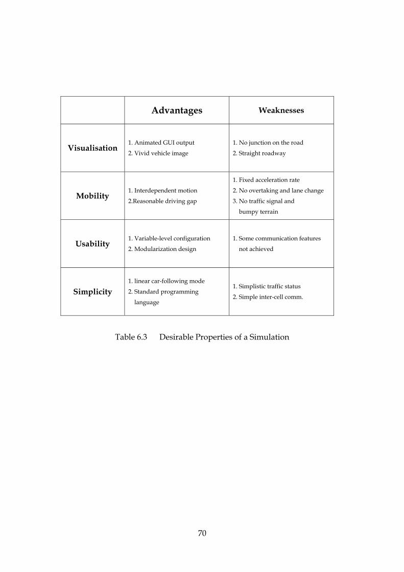
Advantages Weaknesses
Visualisation 1. Animated GUI output
2. Vivid vehicle image
1. No junction on the road
2. Straight roadway
Mobility 1. Interdependent motion
2.Reasonable driving gap
1. Fixed acceleration rate
2. No overtaking and lane change
3. No traffic signal and
bumpy terrain
Usability 1. Variable-level configuration
2. Modularization design
1. Some communication features
not achieved
Simplicity 1. linear car-following mode
2. Standard programming
language
1. Simplistic traffic status
2. Simple inter-cell comm.
Table 6.3 Desirable Properties of a Simulation
70

Chapter 7
Conclusion
7.1 Summary
In the beginning of this project, we made background research in the fields of
Ad Hoc wireless networks, layered communication protocols, traffic
simulation and MANETs/VANETs simulation.
After research work, we implemented a realistic traffic environment
simulation. Based on vehicular mobility model and GUI-based roadway
layout, the traffic simulation presents the scenarios in which various types of
vehicles are driving forward through the whole lane. The motion of an
on-screen vehicle follows the shape of the roadway as well as interacts with
the movement of nearby vehicles. We also represented a number of base
stations and cells in the simulation.
On top of the traffic environment simulation we simulated vehicle-to-vehicle
communication and vehicle-to-roadside communication by the rules of the
TBMAC protocol.
Upon implementing the simulation, we investigated its performance and
evaluated the features it present.
71
7.2 Future Works
Traffic simulation is a complex system that attracts a lot of research interest.
This project follows some sophisticated theoretics, algorithms and approaches
to implement a microscopic small-scale traffic simulation. Some functional
limitations in this simulation made it unsuitable to perform large wireless
network simulation.
Thereby, the first step of future work is to enhance the vehicular mobility
model. For instance, to make the traffic simulation more realistic, we should
add the overtaking and lane change functions. The terrain should be
diversiform. The diverse terrains pose different effects on the speed of the
vehicle.
The development of TBMAC API is in progress. To boost the improvement of
TBMAC API is another important task in the future. The TBMAC protocol has
close relationship with higher layer protocols. It is necessary to provide a
interface so as to facilitate the communication between MAC layer and higher
layers.
In addition, communications in VANETs demands multi-layer collaboration.
The advance of higher layer (e.g. some routing protocols) also will speed up
the progress of the TBMAC layer.
72
7.3 Lessons Learned
In this project we utilize Java language to program the simulation. The Java’s
powerful graphical packets make work on GUI easier than expected. More
important, discrete event models are represented as a set of active entities. In
Java language, thread method is well suitable to manifest a group of active
entities. Therefore, Java thread gives a great support to simulate discrete
event-based scenarios.
As an Object-Oriented language, Java programming, no doubt, smooths the
progress of implementing the modularization design, and thus make cross
layer wireless network simulation possible.
In the end, we learned from this project that translating communication
protocols into the implementation on top of simulators is also a challenging
work.
73
Bibliography
[1] D. D. Perkins, H. D. Hughes, and C. B. Owen, “Factors affecting the
performance of ad hoc networks,” presented at the IEEE Int. Conf.
Communications,New York, 2002.
[2] X. Yang, J. Liu, F. Zhao, and N. Vaidya, “A Vehicle-to-Vehicle
Communication Protocol for Cooperative Collision Warning,” in Proc.
MobiQuitous 2004, Boston, MA, USA, August 2004.
[3] Xu, Q., Mak, T., Ko, J. and Sengupta, R., “Vehicle-to-vehicle safety messaging
in DSRC.” in Proceedings of the first ACM workshop on Vehicular ad hoc
networks, (2004), ACM Press.
[4] B. Xu, A. Ouksel, and O.Wolfson, “Opportunistic resource exchange in
inter-vehicle ad-hoc networks,” presented at the IEEE Int. Conf. Mobile Data
Management, Berkeley, CA, Jan. 2004.
[5] Rodolfo Oliveira, Luis Bernardo, Paulo Pinto, “Flooding Techniques for
Resource Discovery on High Mobility MANETs”, iwwan2005
[6] Q. Xu, R. Sengupta, and D. Jiang. “Design and Analysis of Highway Safety
Communication Protocol in 5.9 GHz Dedicated Short Range Communication
Spectrum”. In IEEE VTC 2003 Spring, 2003.
74

[7] Y.-B. Ko and N. H. Vaidya, “GeoTORA: A protocol for geocasting in mobile ad
hoc networks,” presented at the International Conf. Network Protocols, Osaka,
Japan, Nov. 2000.
[8] K. A. Redmill, M. P. Fitz, S. Nakabayashi, T. Ohyama, F. Ozguner’’’]]]],
U.Ozguner, O. Takeshita, K. Tokuda, and W. Zhu, “An incident warning system
with dual frequency communications capability,” presented at the IEEE Intelligent
Vehicles Symp., Columbus, OH, June 2003.
[9] J. Blum and A. Eskandarian and L Hoffman. "Challenges of Intervehicle Ad
Hoc Networks" IEEE Transaction on Intelligent Transportation Systems,
5(4):347--351. 2004.
[10] T. Nadeem, S. Dashtinezhadd, C. Liao, and L. Iftode. “TrafficView:
Traffic Data Dissemination Using Car-to-Car Communication. “ACM Sigmobile
Mobile Computing and Communications Review, Special Issue on Mobile
Data Management, 19, July 2004.
[11] R. A. Santos, R. M. Edwards AMIEE, MIEEE and N. L. Seed, “Supporting
Inter-Vehicular and Vehicle-Roadside Communications over a Cluster-Based
Wireless Ad-Hoc Routing Algorithm”, WISICT 2004, University of Sheffield.
[12] P. Johansson, T. Larsson, N. Hedman, B. Mielczarek, and M.Degermark,
“Scenario-based performance analysis for routing protocols for mobile ad-hoc
networks,” presented at the Annu. Int. Conf. Mobile Computing and
Networking, Seattle, WA, Aug. 1999.
75

[13] L. E. Owen, Y. Zhang, L. Rao, and G. McHale, “Traffic flow simulation
using CORSIM,” presented at the 2000 Winter Simulation Conf., Orlando, FL,
Dec. 2000.
[14] J. Broch, D. A. Maltz, D. B. Johnson, Y.-C. Hu, and J. Jetcheva, “A
performance comparison of multi-hop wireless ad hoc network routing protocols,”
presented at the 4th Annu. ACM/IEEE Int. Conf. Mobile Computing and
Networking, Dallas, TX, 1998.
[15] K. A. Redmill, M. P. Fitz, S. Nakabayashi, T. Ohyama, F. Ozguner, U.
Ozguner, O. Takeshita, K. Tokuda, and W. Zhu, “An incident warning system
with dual frequency communications capability” presented at the IEEE Intelligent
Vehicles Symp., Columbus, OH, June 2003.
[16] H. Hartenstein, B. Bochow, A. Ebner, M. Lott, M. Radimirsch, and D.
Vollmer “Position-Aware Ad Hoc Wireless Networks for Inter-Vehicle
Communications: the Fleetnet Project” In Proc. ACM Mobihoc’01, 2001.
[17] Wu, H., R. Fujimoto, R. Guensler, M. Hunter. “MDDV: A Mobility-Centric
Data Dissemination Algorithm for Vehicular Networks” In Proceedings of the
First ACM Workshop on Vehicular Ad Hoc Networks (VANET) in
conjunction with Mobicom. October 2004.
[18] N. Abramson, “The Throughput of Packet Broadcasting Channels” IEEE
Trans. Commun., vol. COM-25, no. 10, Jan 1977.
76
[19] M. Ergen, et al., “Wireless Token Ring Protocol,” SCI 2002.
[20] Christopher Carlson, Wendy Cheng, Juli Satoh “Daimler-Chrysler Shift
Simulator Design Document”, ME210,1998.
[21] Y. Wang and J. J. Garcia-Luna-Aceves. “A New Hybrid Channel Access
Scheme for Ad Hoc Networks”, ACM WINET Journal, Special Issue on Ad-Hoc
Networks, Vol. 10, No. 4, July 2004.
[22] L. Briesemeister and G. Hommel, “Disseminating Messages among Highly
Mobile Hosts Based on Inter-vehicle Communication”, IEEE Intelligent Vehicle
Symposium, Piscataway NJ, 2000.
[23] G.Cugola, E. D. Nitto and A. Fuggetta, "The JEDI event-based infrastructure
and its application to the development of the OPSS WFMS", IEEE Transactions on
Software Engineering, 27 (9). pp.827-858, 2001.
[24] Helbing, D., et al., “Micro- and Macrosimulation of Freeway Traffic”,
Mathematical and Computer Modelling, pp. 517-547, 2002.
[25] Burghout, W., H. Koutsopoulos, and I. Andreasson, “Loading of vehicles in
microscopic simulation models”, International Journal of Transportation
Management: Submitted for review, 2004.
[26] X. Zeng, R. L. Bagrodia, and M. Gerla. “GloMoSim: a library for parallel
simulation of large-scale wireless networks.” In PADS, May 1998.
77
[27] ns-2 - the network simulator, http://www.isi.edu/nsnam/ns/.
[28] Kopetz, Hermann, “Real-Time Systems: Design Principles for Distributed
Embedded Applications”, Kluwer Academic Publishers, 1997.
[29] DSRC—Dedicated Short Range Communications Project,
http://www.leearmstrong.com/DSRC/DSRCHomeset.htm.
[30] C2C-CC - Car-to-Car Communication Consortium,
http://www.car-to-car.org.
[31] Internet ITS - Internet ITS Consortium, http://www.internetits.org.
[32] Sunil Kumar, Vineet S. Raghavan , Jing Deng “ Medium Access Control protocols for ad hoc wireless networks: A survey”, Ad Hoc Networks 4 (2006) 326–358
[33] C. Schroth, F. Doetzer, T. Kosch, B. Ostermaier, M. Strassberger
”Simulating the traffic effects of vehicle-to-vehicle messaging systems” In
Proceedings of the 5th IEEE International Conference on ITS
Telecommunications, Brest, France, June 2005.
[34] R. Jain, “The art of computer performance analysis: Techniques for Experimental
Design, Measurement, Simulation and Modelling” , Wiley, 1991.
[35] HEIDEMANN, J., BULUSU, N., ELSON, J., INTANAGONWIWAT, C.,
CHAN LAN, K., XU, Y., YE, W.,ESTRIN, D., AND GOVINDAN, R. “Effects of
detail in wireless network simulation.” In Proc. of SCS Multiconference (2001).
78

[36] J. Misra, “Distributed discrete event simulation” ACM Computing Surveys,
18(1):39–65, Mar. 1986
[37] WU, H., FUJIMOTO, R., GUENSLER, R., AND HUNTER, M. “Mddv: a
mobility-centric data dissemination algorithm for vehicular networks” In Proc. of
ACM VANET (2004).
[38] R.Jayakrishnan, Cristian E.Cortes, Riju Lavanya, Laia Pages, “Simulation
of Urban Transportation Networks with Multiple Vehicle Classes and Services:
Classifications, Functional Requirements and General-Purpose Modeling Schemes”
Institute of Transportation Studies, University of California, Irvine, CA
92697-3600, U.S.A. August 2002
[39] Law and Kelton, Simulation Modeling and Analysis, 2nd ed., McGraw Hill,
New York 1991
[40] Shewchuk, J.P. & Chang, T.C. 1991. "An approach to object-oriented discrete
event simulation of manufacturing systems." Proceedings Winter Simulation
Conference, Phoenix, Arizona, USA: IEEE: 302-311.
[41] JiST / SWANS - Java in Simulation Time / Scalable Wireless Ad hoc
Network Simulator, http://jist.ece.cornell.edu/jist-user/index.html
[42] Wilco Burghout, Haris N. Koutsopoulos, Ingmar Andreasson “Hybrid
Mesoscopic-Microscopic Traffic Simulation”, Centre for traffic simulation (CTR),
Royal Institute of Technology, SE-10044 Stockholm, Sweden.
79

[43] Kane Kim and Yuqing Li “Toward Easily Analyzable Sensor Networks via
Structuring of Time-Triggered Tasks” Proc. FTDCS 2003 (9th IEEE Workshop on
Future Trends of Distributed Computing Systems), San Juan, Puerto Rico,
May 2003, pp. 344-351.
[44] Rahnema, M. “Overview of the GSM system and protocol architecture. “ IEEE
Communications Magazine 31, 4 (Apr 1993), 92–100.
[45] P. Karn, "MACA—A new channel access method for packet radio," in
ARRL/CRRL Amateur Radio 9th Computer Networking Conference, 1990,
pp. 134–140.
[46] Riadh DHAOU, Vincent GAUTHIER, M. Issoufou Tiado, Monique
BECKER, Andre-Luc BEYLOT “Cross Layer Simulation: Application to
Performance Modelling of Networks composed of MANETs and Satellites”
[47] Andrew S. Tanenbaum “Computer Networks, Fourth Edition”, Prentice Hall,
ISBN : 0-13-066102-3, March 17, 2003
[48] Rothery, R. W. “Car following models. In Trac Flow Theory (1992)”,
Transportation Research Board, Special Report 165.
[49] R. M. Fujimoto. “Parallel and distributed simulation.” In Winter Simulation
Conf., pages 118–125, Dec. 1995.
[50] Thomas W. Carley, “Sidh: A Wireless Sensor. Network Simulator” ISR Technical Reports,. 2004.
80

[51] “DSRC—Dedicated Short Range Communications Project,” http://www.leearmstrong.com/DSRC/DSRCHomeset.htm.
[52] PERKINS, C. “Ad hoc on demand distance vector (aodv) routing”, 1997.
[53] PERKINS, C., AND BHAGWAT, P. Highly, “dynamic destination sequenced
distance-vector routing (DSDV) for mobile computers”, In Proc. of ACM
SIGCOMM (1994).
[54] Levis P., Lee N., Welsh M., Culler D. 2003. “TOSSIM: Accurate and Scalable
Simulation of Entire TinyOS Applications” In Proceedings of the ACM
Conference on Embedded Networked Sensor Systems (SenSys), 2003.
[55] Perrone L. F., Nicol D. 2002. “A Scalable Simulator for TinyOS
Applications“ In Proceedings of the Winter Simulation Conference, 2002.
[56] S. Marti, T. J. Giuli, K. Lai, and M. Baker, “Mitigating routing misbehavior in
mobile ad hoc networks,” presented at the Annu. Int. Conf. Mobile Computing
and Networking, Boston, MA, Aug. 2000.
[57] Bonnmotion - a mobility scenario generation and analysis tool.”
http://web.informatik.uni-bonn.de/IV/Mitarbeiter/dewaal/BonnMotion.
[58] Vissim - Visual Traffic Simulation
http://www.tomfotherby.com/Contents/Education/Project/index.html
[59] SUMO – Simulation of Urban Mobility,
http://sumo.sourceforge.net/overview.shtml
81
[60] STRAW - STreet RAndom Waypoint - vehiclar mobility model for
network simulations
http://www.aqualab.cs.northwestern.edu/projects/STRAW/index.php
82