yamada air-operated diaphragm pumps dp 10 manual.pdf · maintenance manual yamada air-operated...
TRANSCRIPT

MAINTENANCE MANUAL
YAMADA AIR-OPERATED DIAPHRAGM PUMPS
DP-10 series
Doc. No. NDP015M-14
WARNING ▪ For your own safety, be sure to read procedures carefully before performing
maintenance on this product. After reading this document, be sure to keep it handy for future reference.
This maintenance manual covers what you should know about maintenance of the Yamada DP-10 series Diaphragm Pumps. This edition is based on the standards for the March 2009 production run. Remember, the specifications are always subject to change; therefore, some of the information in this edition may not apply to new specifications.
·Warnings and Cautions For safe use of this product, be sure to note the following: In this document, warnings and cautions are indicated by symbols. These symbols are for those who will operate this product and for those who will be nearby, for safe operation and for prevention of personal injury and property damage. The following warning and caution symbols have the meanings described below. Be sure to remember their meanings.
If you ignore the warning described and operate the product in an improper manner, there is danger of serious bodily injury or death. If you ignore the caution described and operate the product in an improper manner, there is danger of personal injury or property damage.
Furthermore, to indicate the type of danger and damage, the following symbols are also used along with those mentioned above:
This symbol indicates a DON'T, and will be accompanied by an explanation on something you must not do.
This symbol indicates a DO, and will be accompanied by instructions on something you must do in a certain situation.
WARNING ▪ Before starting maintenance work, cut off the feed air and clean the pump. If air pressure or
residue remain in the pump, there is danger of explosion, or possible poisoning resulting in serious injury or death if chemicals adhere to the skin or are accidentally swallowed.
(For details on cleaning the pump, refer to Chapter 6 of the operating manual.)
▪ When replacing parts, be sure to use the recommended genuine parts or Equivalents. Use of other parts may cause a malfunction of the product.
CAUTION ▪ When it is instructed that special tools must be used, be sure to use the specified tools.
Otherwise, the pump may be damaged.
▪ Refer to 10.1 "Specifications" in the Operating Manual. Also, remember that the pump is heavy, and extreme care must be taken when lifting it.
WARNING :
CAUTION :
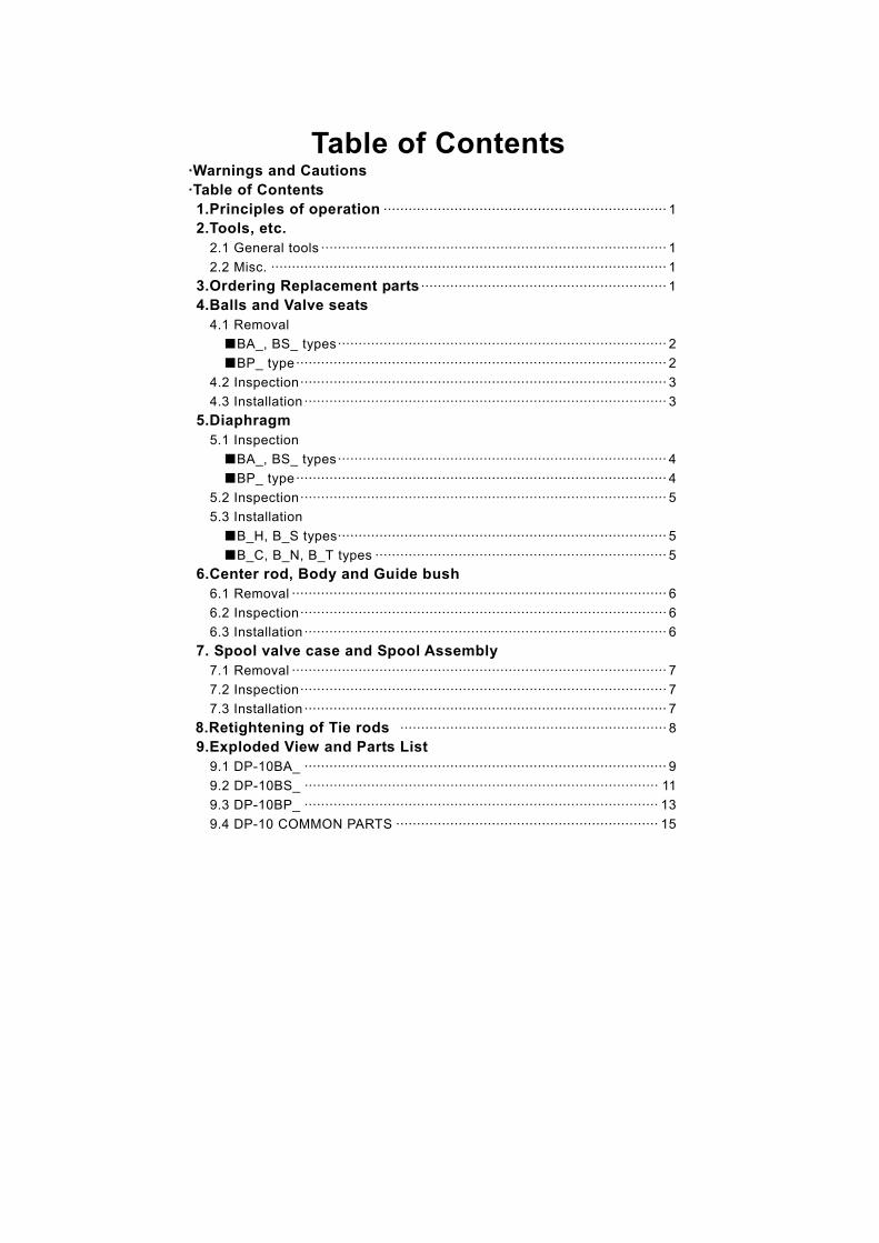
Table of Contents ·Warnings and Cautions
·Table of Contents
1.Principles of operation ···································································· 1
2.Tools, etc. 2.1 General tools ··················································································· 1
2.2 Misc. ······························································································· 1
3.Ordering Replacement parts ··························································· 1
4.Balls and Valve seats 4.1 Removal
■BA_, BS_ types··············································································· 2
■BP_ type ························································································· 2
4.2 Inspection························································································ 3
4.3 Installation ······················································································· 3
5.Diaphragm 5.1 Inspection
■BA_, BS_ types··············································································· 4
■BP_ type ························································································· 4
5.2 Inspection························································································ 5
5.3 Installation
■B_H, B_S types··············································································· 5
■B_C, B_N, B_T types ······································································ 5
6.Center rod, Body and Guide bush 6.1 Removal ·························································································· 6
6.2 Inspection························································································ 6
6.3 Installation ······················································································· 6
7. Spool valve case and Spool Assembly 7.1 Removal ·························································································· 7
7.2 Inspection························································································ 7
7.3 Installation ······················································································· 7
8.Retightening of Tie rods ································································ 8 9.Exploded View and Parts List 9.1 DP-10BA_ ······················································································· 9
9.2 DP-10BS_ ····················································································· 11
9.3 DP-10BP_ ····················································································· 13
9.4 DP-10 COMMON PARTS ······························································· 15

1
1.Principles of operation There are two diaphragms fixed to the center rod, one at each end. When compressed air is supplied to air chamber b (right side, see Fig. 1.1), the center rod moves to the right, the material in material chamber B is pushed out, and at the same time material is sucked into material chamber A. When the center rod is moved full-stroke to the right, the air switch valve is switched, compressed air is sent to air chamber a (left side, see Fig.1.2), and the center rod moves to the left. The material in material chamber A is pushed out, and at the same time material is sucked into material chamber B.
Through repetition of this operation, material is repeatedly taken in and discharged out.
2.Tools, etc. 2.1 General tools ·Socket wrenches 13mm ·Hexagonal box wrenches 5mm, 6mm ·Open-end wrenches 21mm(BP_)
·Snap ring plyer
2.2 Misc. ·Assembly oil Turbine oil none addition class 1( equivalent to ISO VG32 grade ) ·Nuts M8×1.25 (BA_, BS_)
· Grease Urea grease grade (NLGI) No.2
3.Ordering Replacement parts For accurate and speedy shipment of parts, be sure to order the right parts for your model to distributor. Indicate the part numbers, descriptions, and quantities.
2
4.Balls and Valve seats 4.1 Removal ■ BA_, BS_ types See [9. Exploded View] on after p.9.(Fig. 4.1, 4.2, 4.3 and 4.4 show the DP-BA_.)
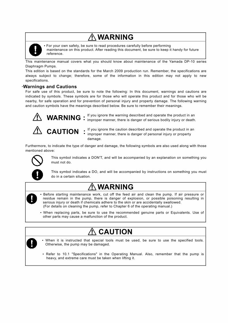
▪ Remove the 4 retainer bolts from the out manifold, and remove the out manifold. [Fig.4.1]
▪ Remove the O ring, valve stopper, ball and valve seat. [Fig.4.2]
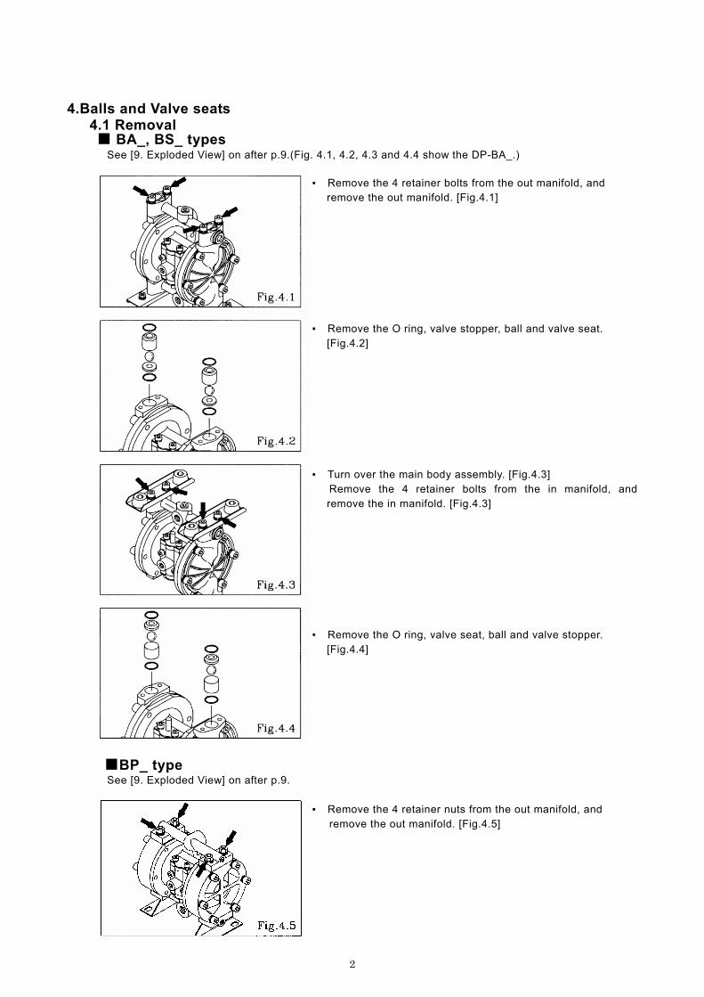
▪ Turn over the main body assembly. [Fig.4.3] Remove the 4 retainer bolts from the in manifold, and
remove the in manifold. [Fig.4.3]
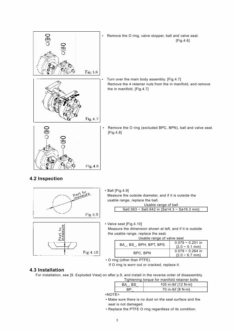
▪ Remove the O ring, valve seat, ball and valve stopper.
[Fig.4.4]
■BP_ type See [9. Exploded View] on after p.9.
▪ Remove the 4 retainer nuts from the out manifold, and remove the out manifold. [Fig.4.5]
3
▪ Remove the O ring, valve stopper, ball and valve seat. [Fig.4.6]
▪ Turn over the main body assembly. [Fig.4.7] Remove the 4 retainer nuts from the in manifold, and remove the in manifold. [Fig.4.7]
▪ Remove the O ring (excluded BPC, BPN), ball and valve seat.
[Fig.4.8]
4.2 Inspection
▪ Ball [Fig.4.9]
Measure the outside diameter, and if it is outside the usable range, replace the ball.
Usable range of ball Sø0.563 ~ Sø0.642 in {Sø14.3 ~ Sø16.3 mm}
▪ Valve seat [Fig.4.10] Measure the dimension shown at left, and if it is outside the usable range, replace the seat.
Usable range of valve seat
BA_, BS_, BPH, BPT, BPS 0.079 ~ 0.201 in {2.0 ~ 5.1 mm}
BPC, BPN 0.079 ~ 0.264 in {2.0 ~ 6.7 mm}
▪ O ring (other than PTFE) If O ring is worn out or cracked, replace it.
4.3 Installation For installation, see [9. Exploded View] on after p.9, and install in the reverse order of disassembly.
Tightening torque for manifold retainer bolts
BA_, BS_ 105 in-lbf {12 N-m}
BP_ 70 in-lbf {8 N-m}
<NOTE> ▪ Make sure there is no dust on the seal surface and the
seal is not damaged. ▪ Replace the PTFE O ring regardless of its condition.

4
5.Diaphragm 5.1 Removal ■BA_, BS_ types See [9. Exploded View] on after p.9. (Fig.5.1 and 5.2 show the DP-BA_.)
▪ Remove the ball and valve seat etc.(see [ 4.1 Removal BA_, BS_ types] on p. 4) ▪ Remove the 12 retainer bolts from the out chamber, and
remove the out chamber. [Fig.5.1]
▪ Remove the nuts on both sides of the center rod. [Fig.5.2] ▪ After the nuts on one side have been removed, remove the
center disk and diaphragm. [Fig.5.2]
▪ Remove the nuts on the opposite side using the double nut. [Fig.5.3] ▪ Remove the coned disk spring, center disk and diaphragm.
■BP_ type See [9. Exploded View] on after p.9
▪ Remove the ball and valve seat etc.(see [ 4.1 Removal BP_
type] on p. 2) ▪ Remove the 12 retainer bolts from the out chamber, and
remove the out chamber. [Fig.5.4]
▪ Remove the center disk from one side. [Fig.5.5] ▪ After the center disk (outside) has been removed, remove the
diaphragm and the center disk (inside).

5
▪ Remove the center disk and diaphragm from the opposite
side using the double nut. [Fig.5.6] Be careful not to scratch or score the center rod.
5.2 Inspection ▪ Diaphragm
If the diaphragm is worn out or damaged, replace it. New replace just one diaphragm.
Guideline of diaphragm life CR, NBR, PTFE 10,000,000 cycle
TPEE, TPO 15,000,000 cycle (When used with clean water at room temperature)
5.3 Installation ■B_H, B_S types For installation, see [9. Exploded View] on after p.9, and install in the reverse order of disassembly. ▪ Apply assembly grease to the center rod, and insert it into
the main body. ▪ Keep the convex side to the outside (cf.Fig.5.7). ▪ Tighten the center disk using the open-end wrenches for the DP-10BP_. (No coned disk springs and nuts are needed.) ▪ Tighten the out chamber temporarily at first. ▪ After installation of the out chambers on both sides, place the
pump on a flat surface and stand the pump upright for further assembly.
Tightening torque for center rod and out chamber Center rod Out chamber
122 in-lbf {14 N-m} 105 in-lbf {12 N-m}
<NOTE> ▪ Make sure there is no dust on the seal surface in order to
prevent seal damaged ▪ Tighten the bolts gradually in a diagonal sequence with even
torque. [Fig.5.8].
■B_C, B_N, B_T types
For installation, see [9. Exploded View] on after p. 9, and install in the reverse order of disassembly. ▪ Apply assembly grease to the center rod, and insert it into
the main body. ▪ Keep the marking “LIQUID” to liquid end for CR, NBR
diaphragms. ▪ Keep the convex side to the outside for PTFE diaphragm. ▪ Install the O ring (cf. Fig.5.8). ▪ Tighten the center disk using the open-end wrenches for the DP-10BP_. (No coned disk springs and nuts are needed.) ▪ After installation of the out chambers on both sides, place the
pump on a flat surface and stand the pump upright for further assembly.
Tightening torque for center rod and out chamber. Center rod Out chamber
122 in-lbf {14 N-m} 105 in-lbf {12 N-m} <NOTE>
▪ Make sure there is no dust on the seal surface in order to prevent seal damaged. ▪ Replace the PTFE O ring by new one. ▪ Tighten the bolts gradually in a diagonal sequence with even torque. [Fig.5.10]
Fig.5.8
Fig.5.9
Fig.5.10

6
6.Center rod, Body and Guide bush 6.1 Removal See [9. Exploded View] on after p.9. ▪ Remove the diaphragm etc.(see [5.1 Removal] on p. 4) ▪ Remove the snap ring using the snap ring plyer, and remove
the guide bush, spacer and center rod assembly. [Fig.6.1]
6.2 Inspection
▪ Center rod assembly [Fig.6.2]
Measure the outside diameter (A), and if it is outside the usable range, replace the slipper seal. Usable range of Slipper seal (A)
ø0.783 ~ø0.787 in {ø19.9 ~ø20.0 mm}
Measure the outside diameter (B), and if it is outside the usable range, replace the center rod Slipper seal.
Usable range of Center rod(B) ø0.547 ~ø0.551 in {ø13.9 ~ø14.0 mm}
▪ Sleeve [Fig.6.3]
Measure the inside diameter, and if it is outside the usable range, replace the Sleeve.
Remove the Sleeve from the Spacer side.
Usable range of sleeve ø0.7874 ~ø0.7906 in {ø20.00 ~ø20.08 mm}
▪ Guide bush [Fig.6.4]
Measure the inside diameter, and if it is outside the usable range, replace the guide bush.
Usable range of Guide bush ø0.5520 ~ø0.5544 in {ø14.02 ~ø14.08 mm}
▪ O ring
If the O ring is worn out or cracked, replace it.
6.3 Installation For installation, see [9. Exploded View] on after p.9, and install in the reverse order of disassembly
<NOTE> ▪ Make sure there is no dust on the seal surface and it is
not damaged. ▪ Apply grease to packing.
7
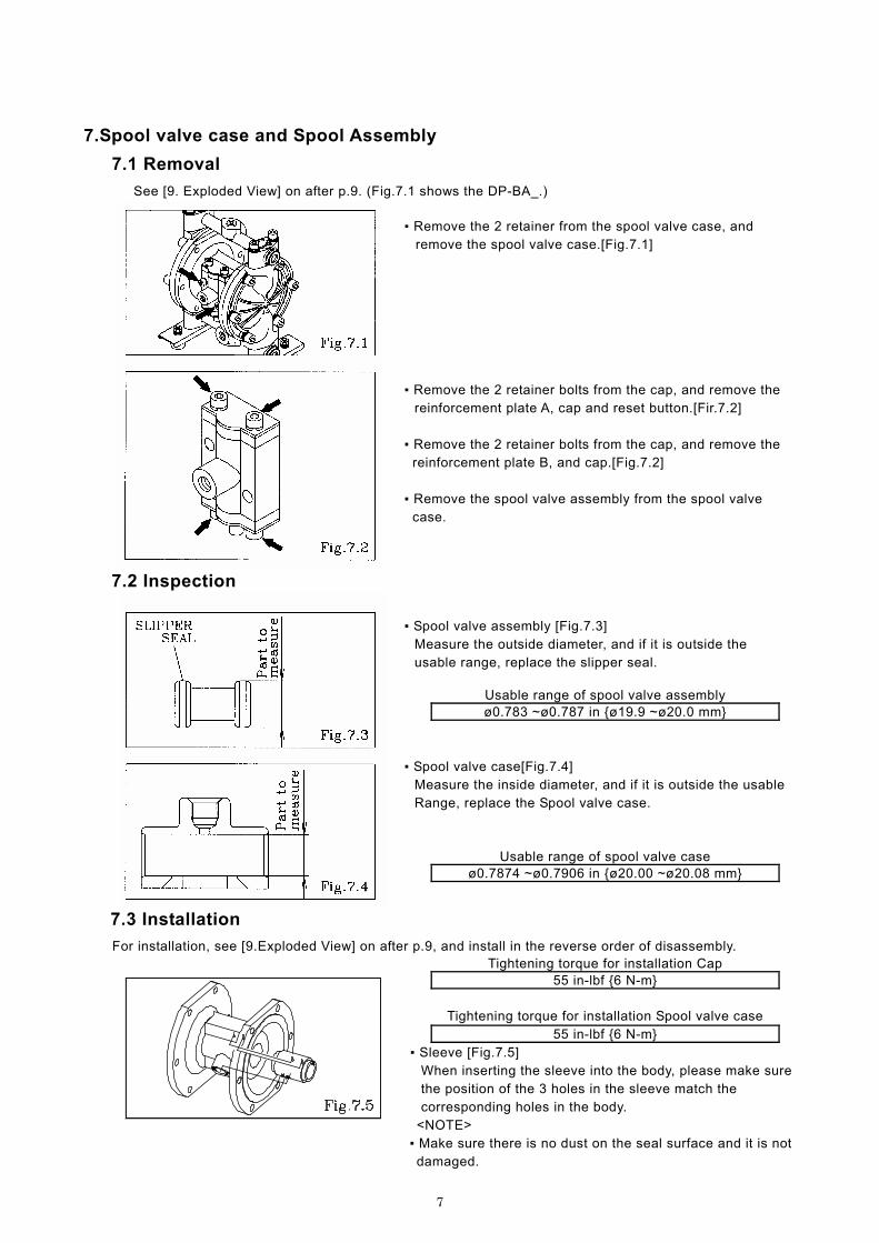
7.Spool valve case and Spool Assembly
7.1 Removal
See [9. Exploded View] on after p.9. (Fig.7.1 shows the DP-BA_.) ▪ Remove the 2 retainer from the spool valve case, and remove the spool valve case.[Fig.7.1] ▪ Remove the 2 retainer bolts from the cap, and remove the
reinforcement plate A, cap and reset button.[Fir.7.2] ▪ Remove the 2 retainer bolts from the cap, and remove the
reinforcement plate B, and cap.[Fig.7.2] ▪ Remove the spool valve assembly from the spool valve
case.
7.2 Inspection
▪ Spool valve assembly [Fig.7.3]
Measure the outside diameter, and if it is outside the usable range, replace the slipper seal.
Usable range of spool valve assembly ø0.783 ~ø0.787 in {ø19.9 ~ø20.0 mm}
▪ Spool valve case[Fig.7.4]
Measure the inside diameter, and if it is outside the usable Range, replace the Spool valve case.
Usable range of spool valve case ø0.7874 ~ø0.7906 in {ø20.00 ~ø20.08 mm}
7.3 Installation
For installation, see [9.Exploded View] on after p.9, and install in the reverse order of disassembly. Tightening torque for installation Cap
55 in-lbf {6 N-m}
Tightening torque for installation Spool valve case
55 in-lbf {6 N-m} ▪ Sleeve [Fig.7.5]
When inserting the sleeve into the body, please make sure the position of the 3 holes in the sleeve match the corresponding holes in the body.
<NOTE> ▪ Make sure there is no dust on the seal surface and it is not damaged.

8
8. Retightening of Tie rods
▪ All bolts should be retorqued:
(1) Right before start up.
(2) There are any leaks of material on daily inspecting a pump.
Retain bolts for the
out chamber Retain bolts for the
manifold
DP-10 BP_ 105 in-lbf {12 N-m} 70 in-lbf {8 N-m}
<NOTE>
▪ Retighten the Out chamber and then the manifold in this order. [Fig.8.1]. ▪ Tighten the bolts in the order shown. [Fig.8.2]
Fig.8.2
9
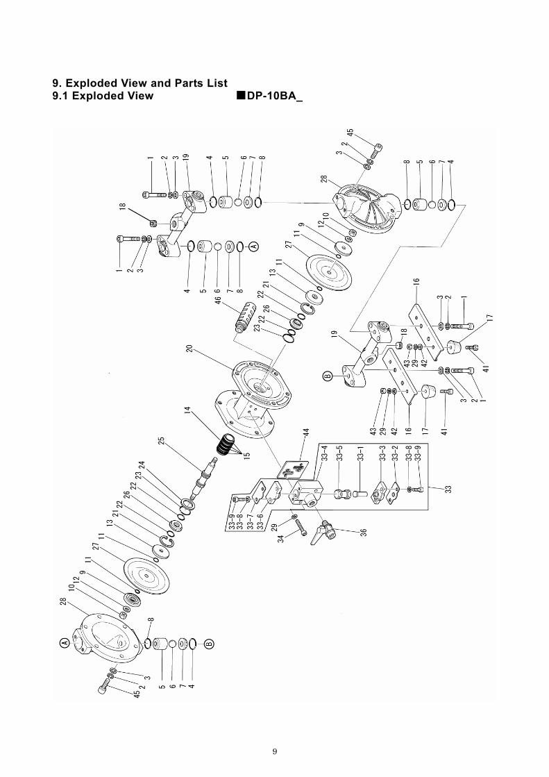
9. Exploded View and Parts List 9.1 Exploded View ■DP-10BA_

10
NO. BA□ DESCRIPTION Q'TY NOTE1 681295 HEXAGON SOCKET HEAD BOLT 8 M8x1.25x452 681300 SPRING LOCK WASHER 203 631329 PLAIN WASHER 204 643018 O RING 4 P21 PTFE5 771368 VALVE STOPPER 46 Tab.1 BALL 47 710638 VALVE SEAT 48 643017 O RING 4 P20 PTFE9 708770 CENTER DISK 2
10 681849 NUT 2 M8x1.2511 Tab.2 O RING 412 684916 CONED DISK SPRING 213 709512 CENTER DISK 214 714678 SLEEVE 115 684900 O RING 416 710586 PUMP BASE 217 771123 CUSHION 418 709872 HEXAGON SOCKET HEAD PLUG 2 3/8"19 802591 MANIFOLD ASSEMBLY 220 715107 BODY 121 630807 RETAINING RING R TYPE 222 684284 PACKING 423 640131 O RING 2 G30 24 772651 SPACER 125 801785 CENTER ROD ASSEMBLY 126 772619 GUIDE BUSH 227 Tab.3 DIAPHRAGM 228 710572 OUT CHAMBER 229 681855 SPRING LOCK WASHER 633 804505 VALVE BODY ASSEMBLY 134 682918 HEXAGON SOCKET HEAD BOLT 2 M6x1x3536 683055 BALL VALVE 1 1/4"41 621102 BOLT 4 M6x1x2242 631328 PLAIN WASHER 443 628010 NUT 4 M6x144 771358 GASKET 145 682944 HEXAGON SOCKET HEAD BOLT 12 M8x1.25x2546 682520 SILENCER 151 790911 NAME PLATE 1
NOTE) NO.51(NAME PLATE) IS NOT INDICATED IN EXPLODED VIEW
9.1 Parts List ■DP-10BA_
11
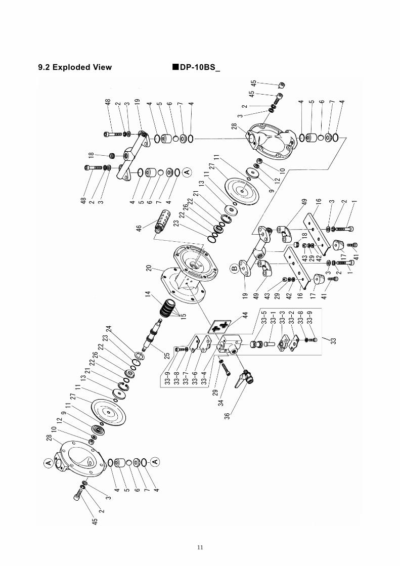
9.2 Exploded View ■DP-10BS_

12
NO. BS□ DESCRIPTION Q'TY NOTE1 682971 HEXAGON SOCKET HEAD BOLT 4 M8x1.25x402 681300 SPRING LOCK WASHER 203 631329 PLAIN WASHER 204 Tab.4 O RING 85 710637 VALVE STOPPER 46 Tab.1 BALL 47 708913 VALVE SEAT 49 708506 CENTER DISK 2
10 681849 NUT 2 M8x1.2511 Tab.2 O RING 412 684916 CONED DISK SPRING 213 709512 CENTER DISK 214 714678 SLEEVE 115 684900 O RING 416 710586 PUMP BASE 217 771123 CUSHION 418 710914 HEXAGON SOCKET HEAD PLUG 2 3/8"19 831559 MANIFOLD ASSEMBLY 220 715107 BODY 121 630807 RETAINING RING R TYPE 222 684284 PACKING 4 MYA-1423 640131 O RING 2 G30 NBR24 772651 SPACER 125 801785 CENTER ROD ASSEMBLY 126 772619 GUIDE BUSH 227 Tab.3 DIAPHRAGM 228 710660 OUT CHAMBER 229 681855 SPRING LOCK WASHER 633 804505 VALVE BODY ASSEMBLY 134 682918 HEXAGON SOCKET HEAD BOLT 2 M6x1x3536 683055 BALL VALVE 1 1/4"41 621102 BOLT 4 M6x1x2242 631328 PLAIN WASHER 443 628010 NUT 4 M6x144 771358 GASKET 145 682944 HEXAGON SOCKET HEAD BOLT 12 M8x1.25x2546 682520 SILENCER 148 681297 HEXAGON SOCKET HEAD BOLT 4 M8x1.25x2049 771380 SPACER 251 790911 NAME PLATE 1
NOTE) NO.51(NAME PLATE) IS NOT INDICATED IN EXPLODED VIEW
9.2 Parts List ■DP-10BS_
13
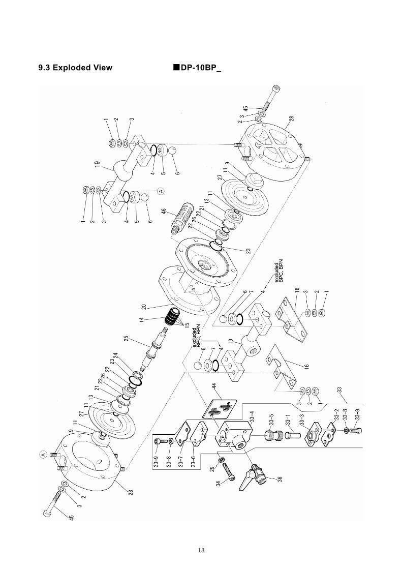
9.3 Exploded View ■DP-10BP_

14
NO. BP□ DESCRIPTION Q'TY NOTE1 628012 NUT 8 M8x1.252 681300 SPRING LOCK WASHER 203 631329 PLAIN WASHER 204 Tab.5 O RING -5 771136 VALVE STOPPER 26 Tab.1 BALL 47 Tab.6 VALVE SEAT 29 770968 CENTER DISK 2
11 Tab.2 O RING 413 708770 CENTER DISK 214 714678 SLEEVE 115 684900 O RING 416 708511 PUMP BASE 219 831316 MANIFOLD ASSEMBLY 220 715107 BODY 121 630807 RETAINING RING R TYPE 222 684284 PACKING 4 MYA-1423 640131 O RING 2 G30 NBR24 772651 SPACER 125 801785 CENTER ROD ASSEMBLY 126 772619 GUIDE BUSH 227 Tab.3 DIAPHRAGM 228 780194 OUT CHAMBER 229 681855 SPRING LOCK WASHER 233 804505 VALVE BODY ASSEMBLY 134 682918 HEXAGON SOCKET HEAD BOLT 2 M6x1x3536 683055 BALL VALVE 1 1/4"44 771358 GASKET 145 682945 HEXAGON SOCKET HEAD BOLT 12 M8x1.25x5046 682520 SILENCER 151 790911 NAME PLATE 1
NOTE) NO.51(NAME PLATE) IS NOT INDICATED IN EXPLODED VIEW
9.3 Parts List ■DP-10BP_

15
Tab.1 BALLTYPE BA/BS/BP□ MATERIAL TYPE BA/BS/BP□ MATERIALB□C 770970 CR B□C 640005 NBRB□N 770972 NBR B□N 640005 NBRB□T 770931 PTFE B□T 643005 PTFEB□H 770972 NBR B□HB□S 771978 EPDM B□S
Tab.3 DIAPHRAGMTYPE BA/BS/BP□ MATERIAL TYPE BS□ MATERIALB□C 770971 CR B□C 640018 NBRB□N 770973 NBR B□N 640018 NBRB□T 770933 PTFE B□T 643018 PTFEB□H 771372 TPEE B□H 640018 NBRB□S 771972 TPO B□S 684112 EPDM
Tab.6 VALVE SEATTYPE BP□ MATERIAL Q'TY TYPE BP□ MATERIALBPC 640018 NBR 2 BPC 770975 CRBPN 640018 NBR 2 BPN 770976 NBRBPT 643018 PTFE 4 BPT 771187 PPGBPH 640018 NBR 4 BPH 771187 PPGBPS 684112 EPDM 4 BPS 771187 PPG
Tab.2 O RING(P8)
Tab.4 O RING(P21)
Tab.5 O RING(P21)
804505 VALVE BODY ASSEMBLYNO. PART NO DESCRIPTION Q'TY NOTE
33-1 706798 PUSH ROD 133-2 710587 REINFORCEMENT PLATE A 133-3 771357 CAP 133-4 710853 SPOOL VALVE CASE 133-5 801404 SPOOL VALVE ASSEMBLY 133-6 771356 CAP 133-7 710636 REINFORCEMENT PLATE B 133-8 681855 SPRING LOCK WASHER 433-9 682943 HEXAGON SOCKET HEAD BOLT 4 M6x1x18
9.4 Parts List ■DP-10 COMMON PARTS

YAMADA AMERICA, INC
955 E. ALGONQUIN RD., ARLINGTON HEIGHTS, IL 60005, USA PHONE: 1-847-631-9200 or 1-800-990-7867 (Toll Free) FAX : 1-847-631-9273
www.yamadapump.com
Manufactured by:
YAMADA CORPORATION International Department 1-1-3 CHOME, MINAMI MAGOME, OHTA-KU, TOKYO, 143-8504, JAPAN PHONE : +81-(0)3-3777-0241 FAX : +81-(0)3-3777-0584
200906 NDP015M