ways for implementing highly-predictable embedded systems ...cdn.intechweb.org/pdfs/29201.pdf ·...
TRANSCRIPT
1
Ways for Implementing Highly-Predictable Embedded Systems Using Time-Triggered
Co-Operative (TTC) Architectures
Mouaaz Nahas and Ahmed M. Nahhas Department of Electrical Engineering, College of Engineering and Islamic Architecture,
Umm Al-Qura University, Makkah, Saudi Arabia
1. Introduction
Embedded system is a special-purpose computer system which is designed to perform a small number of dedicated functions for a specific application (Sachitanand, 2002; Kamal, 2003). Examples of applications using embedded systems are: microwave ovens, TVs, VCRs, DVDs, mobile phones, MP3 players, washing machines, air conditions, handheld calculators, printers, digital watches, digital cameras, automatic teller machines (ATMs) and medical equipments (Barr, 1999; Bolton, 2000; Fisher et al., 2004; Pop et al., 2004). Besides these applications, which can be viewed as “noncritical” systems, embedded technology has also been used to develop “safety-critical” systems where failures can have very serious impacts on human safety. Examples include aerospace, automotive, railway, military and medical applications (Redmill, 1992; Profeta et al., 1996; Storey, 1996; Konrad et al., 2004).
The utilization of embedded systems in safety-critical applications requires that the system should have real-time operations to achieve correct functionality and/or avoid any possibility for detrimental consequences. Real-time behavior can only be achieved if the system is able to perform predictable and deterministic processing (Stankovic, 1988; Pont, 2001; Buttazzo, 2005; Phatrapornnant, 2007). As a result, the correct behavior of a real-time system depends on the time at which these results are produced as well as the logical correctness of the output results (Avrunin et al., 1998; Kopetz, 1997). In real-time embedded applications, it is important to predict the timing behavior of the system to guarantee that the system will behave correctly and consequently the life of the people using the system will be saved. Hence, predictability is the key characteristic in real-time embedded systems.
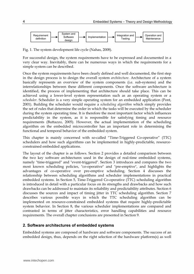
Embedded systems engineers are concerned with all aspects of the system development including hardware and software engineering. Therefore, activities such as specification, design, implementation, validation, deployment and maintenance will all be involved in the development of an embedded application (Fig. 1). A design of any system usually starts with ideas in people’s mind. These ideas need to be captured in requirements specification documents that specify the basic functions and the desirable features of the system. The system design process then determines how these functions can be provided by the system components.
www.intechopen.com
Embedded Systems – Theory and Design Methodology
4
Requirement
definitionImplementation
System and
Software
design
Integration and
Testing
Operation and
Maintenance
Fig. 1. The system development life cycle (Nahas, 2008).
For successful design, the system requirements have to be expressed and documented in a very clear way. Inevitably, there can be numerous ways in which the requirements for a simple system can be described.
Once the system requirements have been clearly defined and well documented, the first step in the design process is to design the overall system architecture. Architecture of a system basically represents an overview of the system components (i.e. sub-systems) and the interrelationships between these different components. Once the software architecture is identified, the process of implementing that architecture should take place. This can be achieved using a lower-level system representation such as an operating system or a scheduler. Scheduler is a very simple operating system for an embedded application (Pont, 2001). Building the scheduler would require a scheduling algorithm which simply provides the set of rules that determine the order in which the tasks will be executed by the scheduler during the system operating time. It is therefore the most important factor which influences predictability in the system, as it is responsible for satisfying timing and resource requirements (Buttazzo, 2005). However, the actual implementation of the scheduling algorithm on the embedded microcontroller has an important role in determining the functional and temporal behavior of the embedded system.
This chapter is mainly concerned with so-called “Time-Triggered Co-operative” (TTC) schedulers and how such algorithms can be implemented in highly-predictable, resource-constrained embedded applications.
The layout of the chapter is as follows. Section 2 provides a detailed comparison between the two key software architectures used in the design of real-time embedded systems, namely "time-triggered" and "event-triggered". Section 3 introduces and compares the two most known scheduling policies, "co-operative" and "pre-emptive", and highlights the advantages of co-operative over pre-emptive scheduling. Section 4 discusses the relationship between scheduling algorithms and scheduler implementations in practical embedded systems. In Section 5, Time-Triggered Co-operative (TTC) scheduling algorithm is introduced in detail with a particular focus on its strengths and drawbacks and how such drawbacks can be addressed to maintain its reliability and predictability attributes. Section 6 discusses the sources and impact of timing jitter in TTC scheduling algorithm. Section 7 describes various possible ways in which the TTC scheduling algorithm can be implemented on resource-constrained embedded systems that require highly-predictable system behavior. In Section 8, the various scheduler implementations are compared and contrasted in terms of jitter characteristics, error handling capabilities and resource requirements. The overall chapter conclusions are presented in Section 9.
2. Software architectures of embedded systems
Embedded systems are composed of hardware and software components. The success of an embedded design, thus, depends on the right selection of the hardware platform(s) as well
www.intechopen.com
Ways for Implementing Highly-Predictable Embedded Systems Using Time-Triggered Co-Operative (TTC) Architectures
5
as the software environment used in conjunction with the hardware. The selection of hardware and software architectures of an application must take place at early stages in the development process (typically at the design phase). Hardware architecture relates mainly to the type of the processor (or microcontroller) platform(s) used and the structure of the various hardware components that are comprised in the system: see Mwelwa (2006) for further discussion about hardware architectures for embedded systems.
Provided that the hardware architecture is decided, an embedded application requires an appropriate form of software architecture to be implemented. To determine the most appropriate choice for software architecture in a particular system, this condition must be fulfilled (Locke, 1992): “The [software] architecture must be capable of providing a provable prediction of the ability of the application design to meet all of its time constraints.”
Since embedded systems are usually implemented as collections of real-time tasks, the various possible system architectures may then be determined by the characteristics of these tasks. In general, there are two main software architectures which are typically used in the design of embedded systems:
Event-triggered (ET): tasks are invoked as a response to aperiodic events. In this case, the system takes no account of time: instead, the system is controlled purely by the response to external events, typically represented by interrupts which can arrive at anytime (Bannatyne, 1998; Kopetz, 1991b). Generally, ET solution is recommended for applications in which sporadic data messages (with unknown request times) are exchanged in the system (Hsieh and Hsu, 2005).
Time-triggered (TT): tasks are invoked periodically at specific time intervals which are known in advance. The system is usually driven by a global clock which is linked to a hardware timer that overflows at specific time instants to generate periodic interrupts (Bennett, 1994). In distributed systems, where multi-processor hardware architecture is used, the global clock is distributed across the network (via the communication medium) to synchronise the local time base of all processors. In such architectures, time-triggering mechanism is based on time-division multiple access (TDMA) in which each processor-node is allocated a periodic time slot to broadcast its periodic messages (Kopetz, 1991b). TT solution can suit many control applications where the data messages exchanged in the system are periodic (Kopetz, 1997).
Many researchers argue that ET architectures are highly flexible and can provide high resource efficiency (Obermaisser, 2004; Locke, 1992). However, ET architectures allow several interrupts to arrive at the same time, where these interrupts might indicate (for example) that two different faults have been detected at the same time. Inevitably, dealing with an occurrence of several events at the same time will increase the system complexity and reduce the ability to predict the behavior of the ET system (Scheler and Schröder-Preikschat, 2006). In more severe circumstances, the system may fail completely if it is heavily loaded with events that occur at once (Marti, 2002). In contrast, using TT architectures helps to ensure that only a single event is handled at a time and therefore the behavior of the system can be highly-predictable.
Since highly-predictable system behavior is an important design requirement for many embedded systems, TT software architectures have become the subject of considerable attention (e.g. see Kopetz, 1997). In particular, it has been widely accepted that TT
www.intechopen.com
Embedded Systems – Theory and Design Methodology
6
architectures are a good match for many safety-critical applications, since they can help to improve the overall safety and reliability (Allworth, 1981; Storey, 1996; Nissanke, 1997; Bates; 2000; Obermaisser, 2004). Liu (2000) highlights that TT systems are easy to validate, test, and certify because the times related to the tasks are deterministic. Detailed comparisons between the TT and ET concepts were performed by Kopetz (1991a and 1991b).
3. Schedulers and scheduling algorithms
Most embedded systems involve several tasks that share the system resources and communicate with one another and/or the environment in which they operate. For many projects, a key challenge is to work out how to schedule tasks so that they can meet their
timing constraints. This process requires an appropriate form of scheduler1. A scheduler can be viewed as a very simple operating system which calls tasks periodically (or aperiodically) during the system operating time. Moreover, as with desktop operating systems, a scheduler has the responsibility to manage the computational and data resources in order to meet all temporal and functional requirements of the system (Mwelwa, 2006).
According to the nature of the operating tasks, any real-time scheduler must fall under one of the following types of scheduling policies:
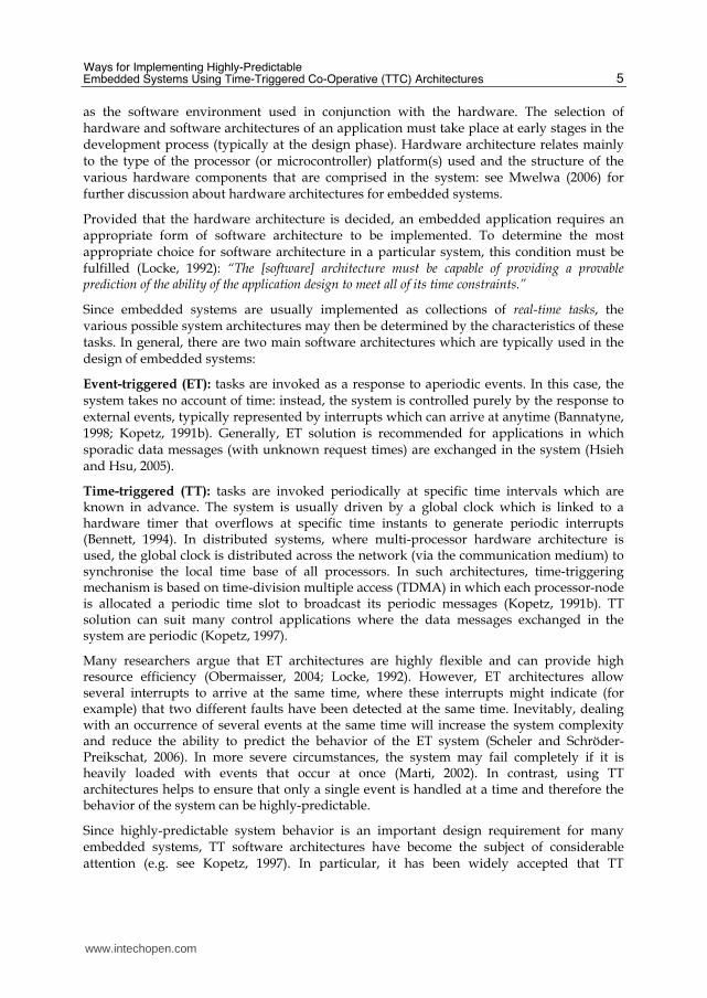
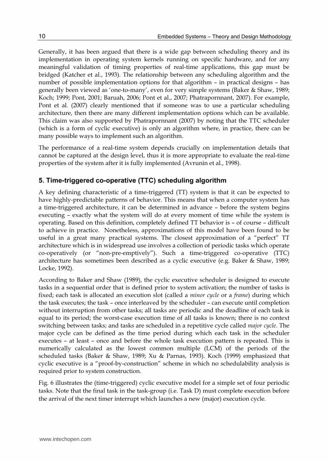
Pre-emptive scheduling: where a multi-tasking process is allowed. In more details, a task with higher priority is allowed to pre-empt (i.e. interrupt) any lower priority task that is currently running. The lower priority task will resume once the higher priority task finishes executing. For example, suppose that – over a particular period of time – a system needs to execute four tasks (Task A, Task B, Task C, Task D) as illustrated in Fig. 2.
A
C
B
D
Time
Fig. 2. A schematic representation of four tasks which need to be scheduled for execution on a single-processor embedded system (Nahas, 2008).
Assuming a single-processor system is used, Task C and Task D can run as required where Task B is due to execute before Task A is complete. Since no more than one task can run at the same time on a single-processor, Task A or Task B has to relinquish control of the CPU.
1 Note that schedulers represent the core components of “Real-Time Operating System” (RTOS) kernels. Examples of commercial RTOSs which are used nowadays are: VxWorks (from Wind River), Lynx (from LynxWorks), RTLinux (from FSMLabs), eCos (from Red Hat), and QNX (from QNX Software Systems). Most of these operating systems require large amount of computational and memory resources which are not readily available in low-cost microcontrollers like the ones targeted in this work.
www.intechopen.com
Ways for Implementing Highly-Predictable Embedded Systems Using Time-Triggered Co-Operative (TTC) Architectures
7
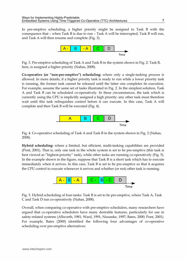
In pre-emptive scheduling, a higher priority might be assigned to Task B with the consequence that – when Task B is due to run – Task A will be interrupted, Task B will run, and Task A will then resume and complete (Fig. 3).
Time
BA - - A C D
Fig. 3. Pre-emptive scheduling of Task A and Task B in the system shown in Fig. 2: Task B, here, is assigned a higher priority (Nahas, 2008).
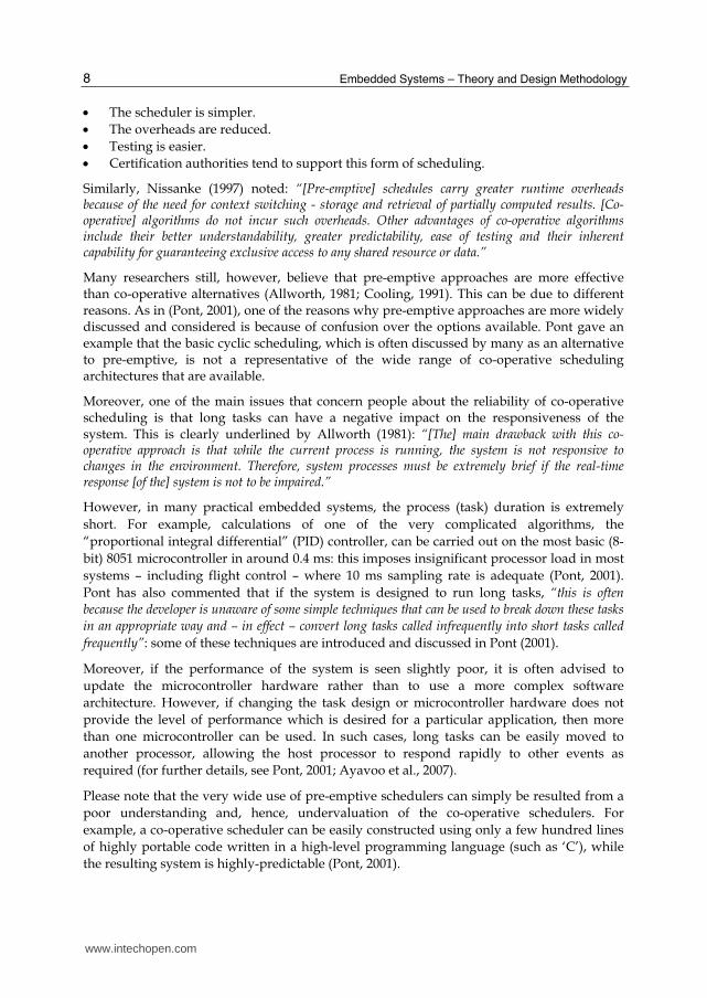
Co-operative (or “non-pre-emptive”) scheduling: where only a single-tasking process is
allowed. In more details, if a higher priority task is ready to run while a lower priority task
is running, the former task cannot be released until the latter one completes its execution.
For example, assume the same set of tasks illustrated in Fig. 2. In the simplest solution, Task
A and Task B can be scheduled co-operatively. In these circumstances, the task which is
currently using the CPU is implicitly assigned a high priority: any other task must therefore
wait until this task relinquishes control before it can execute. In this case, Task A will
complete and then Task B will be executed (Fig. 4).
Time
B C DA
Fig. 4. Co-operative scheduling of Task A and Task B in the system shown in Fig. 2 (Nahas, 2008).
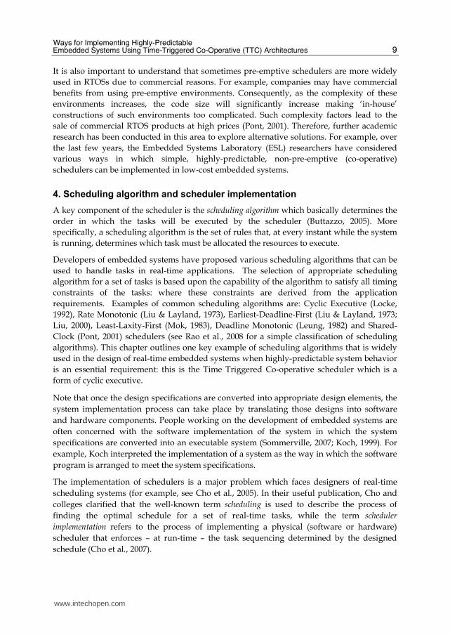
Hybrid scheduling: where a limited, but efficient, multi-tasking capabilities are provided
(Pont, 2001). That is, only one task in the whole system is set to be pre-emptive (this task is
best viewed as “highest-priority” task), while other tasks are running co-operatively (Fig. 5).
In the example shown in the figure, suppose that Task B is a short task which has to execute
immediately when it arrives. In this case, Task B is set to be pre-emptive so that it acquires
the CPU control to execute whenever it arrives and whether (or not) other task is running.
Time
B C - DA - - A B - C
Fig. 5. Hybrid scheduling of four-tasks: Task B is set to be pre-emptive, where Task A, Task C and Task D run co-operatively (Nahas, 2008).
Overall, when comparing co-operative with pre-emptive schedulers, many researchers have
argued that co-operative schedulers have many desirable features, particularly for use in
safety-related systems (Allworth, 1981; Ward, 1991; Nissanke, 1997; Bates, 2000; Pont, 2001).
For example, Bates (2000) identified the following four advantages of co-operative
scheduling over pre-emptive alternatives:
www.intechopen.com
Embedded Systems – Theory and Design Methodology
8
The scheduler is simpler.
The overheads are reduced.
Testing is easier.
Certification authorities tend to support this form of scheduling.
Similarly, Nissanke (1997) noted: “[Pre-emptive] schedules carry greater runtime overheads because of the need for context switching - storage and retrieval of partially computed results. [Co-operative] algorithms do not incur such overheads. Other advantages of co-operative algorithms include their better understandability, greater predictability, ease of testing and their inherent capability for guaranteeing exclusive access to any shared resource or data.”
Many researchers still, however, believe that pre-emptive approaches are more effective than co-operative alternatives (Allworth, 1981; Cooling, 1991). This can be due to different reasons. As in (Pont, 2001), one of the reasons why pre-emptive approaches are more widely discussed and considered is because of confusion over the options available. Pont gave an example that the basic cyclic scheduling, which is often discussed by many as an alternative to pre-emptive, is not a representative of the wide range of co-operative scheduling architectures that are available.
Moreover, one of the main issues that concern people about the reliability of co-operative scheduling is that long tasks can have a negative impact on the responsiveness of the system. This is clearly underlined by Allworth (1981): “[The] main drawback with this co-operative approach is that while the current process is running, the system is not responsive to changes in the environment. Therefore, system processes must be extremely brief if the real-time response [of the] system is not to be impaired.”
However, in many practical embedded systems, the process (task) duration is extremely
short. For example, calculations of one of the very complicated algorithms, the
“proportional integral differential” (PID) controller, can be carried out on the most basic (8-
bit) 8051 microcontroller in around 0.4 ms: this imposes insignificant processor load in most
systems – including flight control – where 10 ms sampling rate is adequate (Pont, 2001).
Pont has also commented that if the system is designed to run long tasks, “this is often because the developer is unaware of some simple techniques that can be used to break down these tasks
in an appropriate way and – in effect – convert long tasks called infrequently into short tasks called
frequently”: some of these techniques are introduced and discussed in Pont (2001).
Moreover, if the performance of the system is seen slightly poor, it is often advised to
update the microcontroller hardware rather than to use a more complex software
architecture. However, if changing the task design or microcontroller hardware does not
provide the level of performance which is desired for a particular application, then more
than one microcontroller can be used. In such cases, long tasks can be easily moved to
another processor, allowing the host processor to respond rapidly to other events as
required (for further details, see Pont, 2001; Ayavoo et al., 2007).
Please note that the very wide use of pre-emptive schedulers can simply be resulted from a
poor understanding and, hence, undervaluation of the co-operative schedulers. For
example, a co-operative scheduler can be easily constructed using only a few hundred lines
of highly portable code written in a high-level programming language (such as ‘C’), while
the resulting system is highly-predictable (Pont, 2001).
www.intechopen.com
Ways for Implementing Highly-Predictable Embedded Systems Using Time-Triggered Co-Operative (TTC) Architectures
9
It is also important to understand that sometimes pre-emptive schedulers are more widely
used in RTOSs due to commercial reasons. For example, companies may have commercial
benefits from using pre-emptive environments. Consequently, as the complexity of these
environments increases, the code size will significantly increase making ‘in-house’
constructions of such environments too complicated. Such complexity factors lead to the
sale of commercial RTOS products at high prices (Pont, 2001). Therefore, further academic
research has been conducted in this area to explore alternative solutions. For example, over
the last few years, the Embedded Systems Laboratory (ESL) researchers have considered
various ways in which simple, highly-predictable, non-pre-emptive (co-operative)
schedulers can be implemented in low-cost embedded systems.
4. Scheduling algorithm and scheduler implementation
A key component of the scheduler is the scheduling algorithm which basically determines the
order in which the tasks will be executed by the scheduler (Buttazzo, 2005). More
specifically, a scheduling algorithm is the set of rules that, at every instant while the system
is running, determines which task must be allocated the resources to execute.
Developers of embedded systems have proposed various scheduling algorithms that can be
used to handle tasks in real-time applications. The selection of appropriate scheduling
algorithm for a set of tasks is based upon the capability of the algorithm to satisfy all timing
constraints of the tasks: where these constraints are derived from the application
requirements. Examples of common scheduling algorithms are: Cyclic Executive (Locke,
1992), Rate Monotonic (Liu & Layland, 1973), Earliest-Deadline-First (Liu & Layland, 1973;
Liu, 2000), Least-Laxity-First (Mok, 1983), Deadline Monotonic (Leung, 1982) and Shared-
Clock (Pont, 2001) schedulers (see Rao et al., 2008 for a simple classification of scheduling
algorithms). This chapter outlines one key example of scheduling algorithms that is widely
used in the design of real-time embedded systems when highly-predictable system behavior
is an essential requirement: this is the Time Triggered Co-operative scheduler which is a
form of cyclic executive.
Note that once the design specifications are converted into appropriate design elements, the
system implementation process can take place by translating those designs into software
and hardware components. People working on the development of embedded systems are
often concerned with the software implementation of the system in which the system
specifications are converted into an executable system (Sommerville, 2007; Koch, 1999). For
example, Koch interpreted the implementation of a system as the way in which the software
program is arranged to meet the system specifications.
The implementation of schedulers is a major problem which faces designers of real-time
scheduling systems (for example, see Cho et al., 2005). In their useful publication, Cho and
colleges clarified that the well-known term scheduling is used to describe the process of
finding the optimal schedule for a set of real-time tasks, while the term scheduler
implementation refers to the process of implementing a physical (software or hardware)
scheduler that enforces – at run-time – the task sequencing determined by the designed
schedule (Cho et al., 2007).
www.intechopen.com
Embedded Systems – Theory and Design Methodology
10
Generally, it has been argued that there is a wide gap between scheduling theory and its implementation in operating system kernels running on specific hardware, and for any meaningful validation of timing properties of real-time applications, this gap must be bridged (Katcher et al., 1993). The relationship between any scheduling algorithm and the number of possible implementation options for that algorithm – in practical designs – has generally been viewed as ‘one-to-many’, even for very simple systems (Baker & Shaw, 1989; Koch; 1999; Pont, 2001; Baruah, 2006; Pont et al., 2007; Phatrapornnant, 2007). For example, Pont et al. (2007) clearly mentioned that if someone was to use a particular scheduling architecture, then there are many different implementation options which can be available. This claim was also supported by Phatrapornnant (2007) by noting that the TTC scheduler (which is a form of cyclic executive) is only an algorithm where, in practice, there can be many possible ways to implement such an algorithm.
The performance of a real-time system depends crucially on implementation details that cannot be captured at the design level, thus it is more appropriate to evaluate the real-time properties of the system after it is fully implemented (Avrunin et al., 1998).
5. Time-triggered co-operative (TTC) scheduling algorithm
A key defining characteristic of a time-triggered (TT) system is that it can be expected to have highly-predictable patterns of behavior. This means that when a computer system has a time-triggered architecture, it can be determined in advance – before the system begins executing – exactly what the system will do at every moment of time while the system is operating. Based on this definition, completely defined TT behavior is – of course – difficult to achieve in practice. Nonetheless, approximations of this model have been found to be useful in a great many practical systems. The closest approximation of a “perfect” TT architecture which is in widespread use involves a collection of periodic tasks which operate co-operatively (or “non-pre-emptively”). Such a time-triggered co-operative (TTC) architecture has sometimes been described as a cyclic executive (e.g. Baker & Shaw, 1989; Locke, 1992).
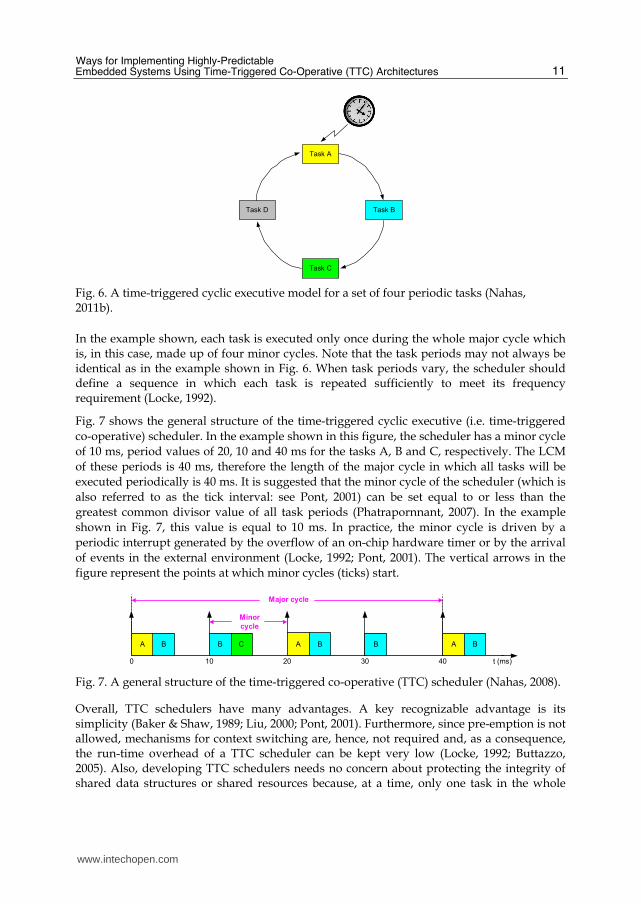
According to Baker and Shaw (1989), the cyclic executive scheduler is designed to execute tasks in a sequential order that is defined prior to system activation; the number of tasks is fixed; each task is allocated an execution slot (called a minor cycle or a frame) during which the task executes; the task – once interleaved by the scheduler – can execute until completion without interruption from other tasks; all tasks are periodic and the deadline of each task is equal to its period; the worst-case execution time of all tasks is known; there is no context switching between tasks; and tasks are scheduled in a repetitive cycle called major cycle. The major cycle can be defined as the time period during which each task in the scheduler executes – at least – once and before the whole task execution pattern is repeated. This is numerically calculated as the lowest common multiple (LCM) of the periods of the scheduled tasks (Baker & Shaw, 1989; Xu & Parnas, 1993). Koch (1999) emphasized that cyclic executive is a “proof-by-construction” scheme in which no schedulability analysis is required prior to system construction.
Fig. 6 illustrates the (time-triggered) cyclic executive model for a simple set of four periodic
tasks. Note that the final task in the task-group (i.e. Task D) must complete execution before
the arrival of the next timer interrupt which launches a new (major) execution cycle.
www.intechopen.com
Ways for Implementing Highly-Predictable Embedded Systems Using Time-Triggered Co-Operative (TTC) Architectures
11
Task B
Task C
Task D
Task A
Fig. 6. A time-triggered cyclic executive model for a set of four periodic tasks (Nahas, 2011b).
In the example shown, each task is executed only once during the whole major cycle which is, in this case, made up of four minor cycles. Note that the task periods may not always be identical as in the example shown in Fig. 6. When task periods vary, the scheduler should define a sequence in which each task is repeated sufficiently to meet its frequency requirement (Locke, 1992).
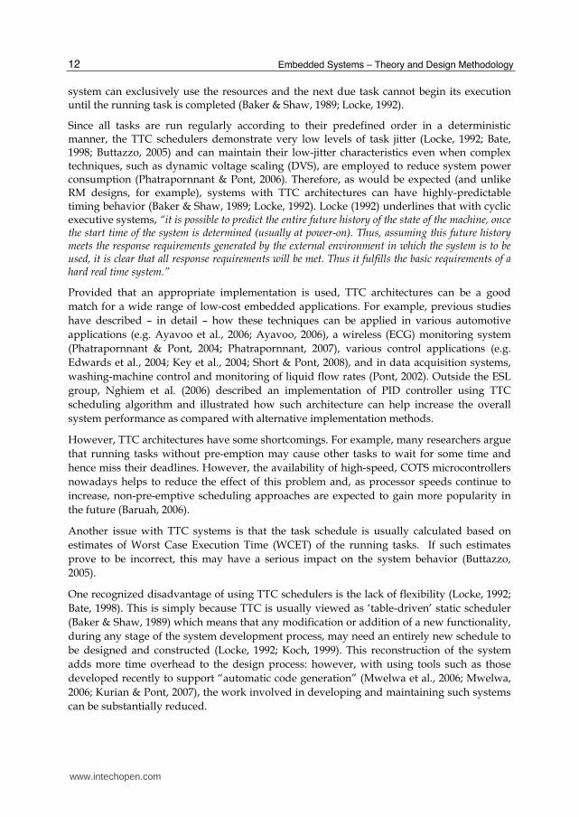
Fig. 7 shows the general structure of the time-triggered cyclic executive (i.e. time-triggered
co-operative) scheduler. In the example shown in this figure, the scheduler has a minor cycle
of 10 ms, period values of 20, 10 and 40 ms for the tasks A, B and C, respectively. The LCM
of these periods is 40 ms, therefore the length of the major cycle in which all tasks will be
executed periodically is 40 ms. It is suggested that the minor cycle of the scheduler (which is
also referred to as the tick interval: see Pont, 2001) can be set equal to or less than the
greatest common divisor value of all task periods (Phatrapornnant, 2007). In the example
shown in Fig. 7, this value is equal to 10 ms. In practice, the minor cycle is driven by a
periodic interrupt generated by the overflow of an on-chip hardware timer or by the arrival
of events in the external environment (Locke, 1992; Pont, 2001). The vertical arrows in the
figure represent the points at which minor cycles (ticks) start.
A C
Minor
cycle
Major cycle
t (ms)0 10 20
A
30 40
B BBB A B
Fig. 7. A general structure of the time-triggered co-operative (TTC) scheduler (Nahas, 2008).
Overall, TTC schedulers have many advantages. A key recognizable advantage is its simplicity (Baker & Shaw, 1989; Liu, 2000; Pont, 2001). Furthermore, since pre-emption is not allowed, mechanisms for context switching are, hence, not required and, as a consequence, the run-time overhead of a TTC scheduler can be kept very low (Locke, 1992; Buttazzo, 2005). Also, developing TTC schedulers needs no concern about protecting the integrity of shared data structures or shared resources because, at a time, only one task in the whole
www.intechopen.com
Embedded Systems – Theory and Design Methodology
12
system can exclusively use the resources and the next due task cannot begin its execution until the running task is completed (Baker & Shaw, 1989; Locke, 1992).
Since all tasks are run regularly according to their predefined order in a deterministic manner, the TTC schedulers demonstrate very low levels of task jitter (Locke, 1992; Bate, 1998; Buttazzo, 2005) and can maintain their low-jitter characteristics even when complex techniques, such as dynamic voltage scaling (DVS), are employed to reduce system power consumption (Phatrapornnant & Pont, 2006). Therefore, as would be expected (and unlike RM designs, for example), systems with TTC architectures can have highly-predictable timing behavior (Baker & Shaw, 1989; Locke, 1992). Locke (1992) underlines that with cyclic executive systems, “it is possible to predict the entire future history of the state of the machine, once the start time of the system is determined (usually at power-on). Thus, assuming this future history meets the response requirements generated by the external environment in which the system is to be used, it is clear that all response requirements will be met. Thus it fulfills the basic requirements of a hard real time system.”
Provided that an appropriate implementation is used, TTC architectures can be a good
match for a wide range of low-cost embedded applications. For example, previous studies
have described – in detail – how these techniques can be applied in various automotive
applications (e.g. Ayavoo et al., 2006; Ayavoo, 2006), a wireless (ECG) monitoring system
(Phatrapornnant & Pont, 2004; Phatrapornnant, 2007), various control applications (e.g.
Edwards et al., 2004; Key et al., 2004; Short & Pont, 2008), and in data acquisition systems,
washing-machine control and monitoring of liquid flow rates (Pont, 2002). Outside the ESL
group, Nghiem et al. (2006) described an implementation of PID controller using TTC
scheduling algorithm and illustrated how such architecture can help increase the overall
system performance as compared with alternative implementation methods.
However, TTC architectures have some shortcomings. For example, many researchers argue
that running tasks without pre-emption may cause other tasks to wait for some time and
hence miss their deadlines. However, the availability of high-speed, COTS microcontrollers
nowadays helps to reduce the effect of this problem and, as processor speeds continue to
increase, non-pre-emptive scheduling approaches are expected to gain more popularity in
the future (Baruah, 2006).
Another issue with TTC systems is that the task schedule is usually calculated based on
estimates of Worst Case Execution Time (WCET) of the running tasks. If such estimates
prove to be incorrect, this may have a serious impact on the system behavior (Buttazzo,
2005).
One recognized disadvantage of using TTC schedulers is the lack of flexibility (Locke, 1992;
Bate, 1998). This is simply because TTC is usually viewed as ‘table-driven’ static scheduler
(Baker & Shaw, 1989) which means that any modification or addition of a new functionality,
during any stage of the system development process, may need an entirely new schedule to
be designed and constructed (Locke, 1992; Koch, 1999). This reconstruction of the system
adds more time overhead to the design process: however, with using tools such as those
developed recently to support “automatic code generation” (Mwelwa et al., 2006; Mwelwa,
2006; Kurian & Pont, 2007), the work involved in developing and maintaining such systems
can be substantially reduced.
www.intechopen.com
Ways for Implementing Highly-Predictable Embedded Systems Using Time-Triggered Co-Operative (TTC) Architectures
13
Another drawback of TTC systems, as noted by Koch (1999), is that constructing the cyclic executive model for a large set of tasks with periods that are prime to each other can be unaffordable. However, in practice, there is some flexibility in the choice of task periods (Xu & Parnas, 1993; Pont, 2001). For example, Gerber et al. (1995) demonstrated how a feasible solution for task periods can be obtained by considering the period harmonicity relationship of each task with all its successors. Kim et al. (1999) went further to improve and automate this period calibration method. Please also note that using a table to store the task schedule is only one way of implementing TTC algorithm where, in practice, there can be other implementation methods (Baker & Shaw, 1989; Pont, 2001). For example, Pont (2001) described an alternative to table-driven schedule implementation for the TTC algorithm which has the potential to solve the co-prime periods problem and also simplify the process of modifying the whole task schedule later in the development life cycle or during the system run-time.
Furthermore, it has also been reported that a long task whose execution time exceeds the period of the highest rate (shortest period) task cannot be scheduled on the basic TTC scheduler (Locke, 1992). One solution to this problem is to break down the long task into multiple short tasks that can fit in the minor cycle. Also, possible alternative solution to this problem is to use a Time-Triggered Hybrid (TTH) scheduler (Pont, 2001) in which a limited degree of pre-emption is supported. One acknowledged advantage of using TTH scheduler is that it enables the designer to build a static, fixed-priority schedule made up of a collection of co-operative tasks and a single (short) pre-emptive task (Phatrapornnant, 2007). Note that TTH architectures are not covered in the context of this chapter. For more details about these scheduling approaches, see (Pont, 2001; Maaita & Pont, 2005; Hughes & Pont, 2008; Phatrapornnant, 2007).
Please note that later in this chapter, it will be demonstrated how, with extra care at the implementation stage, one can easily deal with many of the TTC scheduler limitations indicated above.
6. Jitter in TTC scheduling algorithm
Jitter is a term which describes variations in the timing of activities (Wavecrest, 2001). The
work presented in this chapter is concerned with implementing highly-predictable
embedded systems. Predictability is one of the most important objectives of real-time
embedded systems which can simply be defined as the ability to determine, in advance,
exactly what the system will do at every moment of time in which it is running. One way in
which predictable behavior manifests itself is in low levels of task jitter.
Jitter is a key timing parameter that can have detrimental impacts on the performance of
many applications, particularly those involving period sampling and/or data generation
(e.g. data acquisition, data playback and control systems: see Torngren, 1998). For example,
Cottet & David (1999) show that – during data acquisition tasks – jitter rates of 10% or more
can introduce errors which are so significant that any subsequent interpretation of the
sampled signal may be rendered meaningless. Similarly, Jerri (1977) discusses the serious
impact of jitter on applications such as spectrum analysis and filtering. Also, in control
systems, jitter can greatly degrade the performance by varying the sampling period
(Torngren, 1998; Marti et al., 2001).
www.intechopen.com
Embedded Systems – Theory and Design Methodology
14
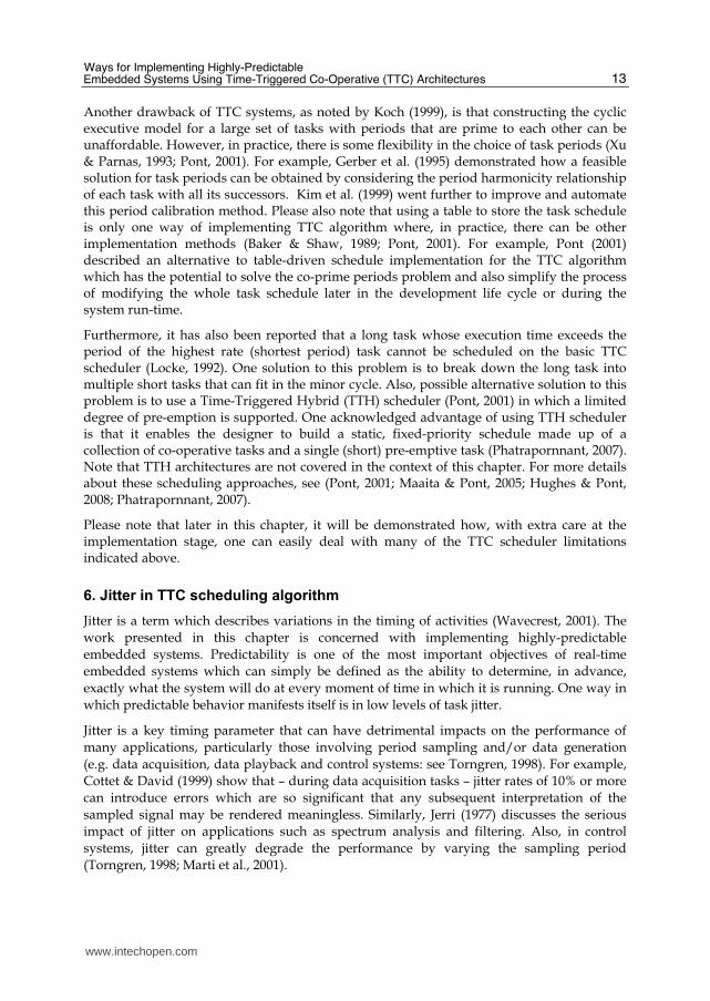
When TTC architectures (which represent the main focus of this chapter) are employed, possible sources of task jitter can be divided into three main categories: scheduling overhead variation, task placement and clock drift.
The overhead of a conventional (non-co-operative) scheduler arises mainly from context switching. However, in some TTC systems the scheduling overhead is comparatively large and may have a highly variable duration due to code branching or computations that have non-fixed lengths. As an example, Fig. 8 illustrates how a TTC system can suffer release jitter as a result of variations in the scheduler overhead (this relates to DVS system).
Speed
Over
head TaskOverheadTask
Task
Period
OverheadTask
Over
headTask
Task
Period
Task
Period
Fig. 8. Release jitter caused by variation of scheduling overhead (Nahas, 2011a).
Even if the scheduler overhead variations can be avoided, TTC designs can still suffer from jitter as a result of the task placement. To illustrate this, consider Fig. 9. In this schedule example, Task C runs sometimes after A, sometimes after A and B, and sometimes alone. Therefore, the period between every two successive runs of Task C is highly variable. Moreover, if Task A and B have variable execution durations (as in Fig. 8), then the jitter levels of Task C will even be larger.
Speed
Task
A
Task
C
Task
Period
Task
Period
Task
Period
Task
C
Task
A
Task
C
Task
B
Task
C
Task
B
Fig. 9. Release jitter caused by task placement in TTC schedulers (Nahas, 2011a).
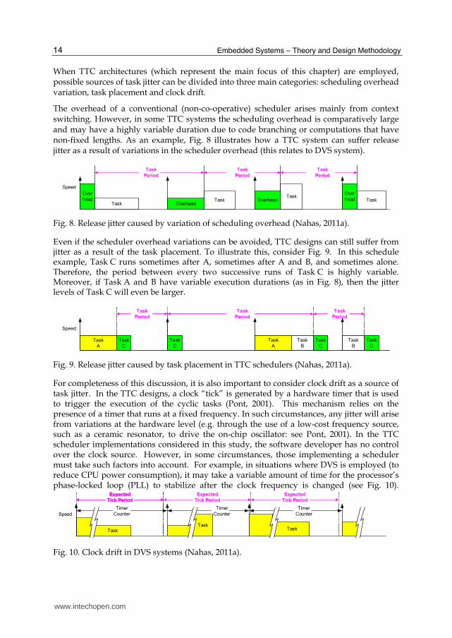
For completeness of this discussion, it is also important to consider clock drift as a source of task jitter. In the TTC designs, a clock “tick” is generated by a hardware timer that is used to trigger the execution of the cyclic tasks (Pont, 2001). This mechanism relies on the presence of a timer that runs at a fixed frequency. In such circumstances, any jitter will arise from variations at the hardware level (e.g. through the use of a low-cost frequency source, such as a ceramic resonator, to drive the on-chip oscillator: see Pont, 2001). In the TTC scheduler implementations considered in this study, the software developer has no control over the clock source. However, in some circumstances, those implementing a scheduler must take such factors into account. For example, in situations where DVS is employed (to reduce CPU power consumption), it may take a variable amount of time for the processor’s phase-locked loop (PLL) to stabilize after the clock frequency is changed (see Fig. 10).
Expected
Tick Period
Expected
Tick Period
Speed
Task
Expected
Tick Period
Expected
Tick Period
Timer
Counter
Task
Timer
Counter
Task
Timer
Counter
Fig. 10. Clock drift in DVS systems (Nahas, 2011a).
www.intechopen.com
Ways for Implementing Highly-Predictable Embedded Systems Using Time-Triggered Co-Operative (TTC) Architectures
15
As discussed elsewhere, it is possible to compensate for such changes in software and thereby reduce jitter (see Phatrapornnant & Pont, 2006; Phatrapornnant, 2007).
7. Various TTC scheduler implementations for highly-predictable embedded systems
In this section, a set of “representative” examples of the various classes of TTC scheduler implementations are reviewed. In total, the section reviews six TTC implementations.
7.1 Super loop (SL) scheduler
The simplest practical implementation of a TTC scheduler can be created using a “Super
Loop” (SL) (sometimes called an “endless loop: Kalinsky, 2001). The super loop can be used
as the basis for implementing a simple TTC scheduler (e.g. Pont, 2001; Kurian & Pont, 2007).
A possible implementation of TTC scheduler using super loop is illustrated in Listing 1.
int main(void)
{
...
while(1)
{
TaskA();
Delay_6ms();
TaskB();
Delay_6ms();
TaskC();
Delay_6ms();
}
// Should never reach here
return 1
}
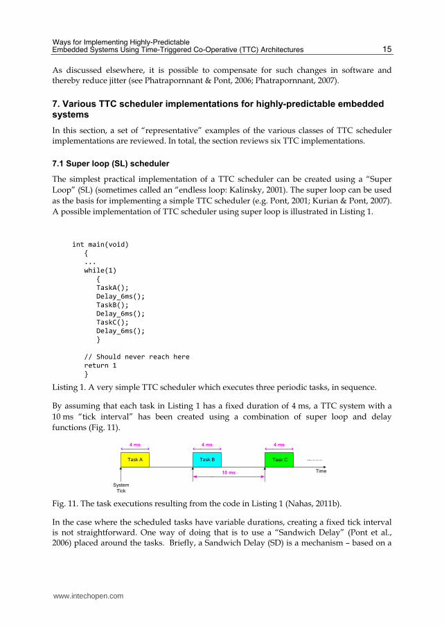
Listing 1. A very simple TTC scheduler which executes three periodic tasks, in sequence.
By assuming that each task in Listing 1 has a fixed duration of 4 ms, a TTC system with a
10 ms “tick interval” has been created using a combination of super loop and delay
functions (Fig. 11).
Time
System
Tick
Task A
10 ms
Task B Task C
4 ms 4 ms 4 ms
Fig. 11. The task executions resulting from the code in Listing 1 (Nahas, 2011b).
In the case where the scheduled tasks have variable durations, creating a fixed tick interval is not straightforward. One way of doing that is to use a “Sandwich Delay” (Pont et al., 2006) placed around the tasks. Briefly, a Sandwich Delay (SD) is a mechanism – based on a
www.intechopen.com
Embedded Systems – Theory and Design Methodology
16
hardware timer – which can be used to ensure that a particular code section always takes approximately the same period of time to execute. The SD operates as follows: [1] A timer is set to run; [2] An activity is performed; [3] The system waits until the timer reaches a pre-determined count value.
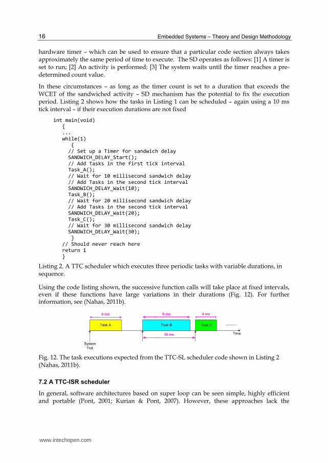
In these circumstances – as long as the timer count is set to a duration that exceeds the WCET of the sandwiched activity – SD mechanism has the potential to fix the execution period. Listing 2 shows how the tasks in Listing 1 can be scheduled – again using a 10 ms tick interval – if their execution durations are not fixed
int main(void) { ... while(1) { // Set up a Timer for sandwich delay SANDWICH_DELAY_Start(); // Add Tasks in the first tick interval Task_A(); // Wait for 10 millisecond sandwich delay // Add Tasks in the second tick interval SANDWICH_DELAY_Wait(10); Task_B(); // Wait for 20 millisecond sandwich delay // Add Tasks in the second tick interval SANDWICH_DELAY_Wait(20); Task_C(); // Wait for 30 millisecond sandwich delay SANDWICH_DELAY_Wait(30); } // Should never reach here return 1 }
Listing 2. A TTC scheduler which executes three periodic tasks with variable durations, in sequence.
Using the code listing shown, the successive function calls will take place at fixed intervals, even if these functions have large variations in their durations (Fig. 12). For further information, see (Nahas, 2011b).
Time
System
Tick
10 ms
Task B Task CTask A
6 ms 9 ms 4 ms
Fig. 12. The task executions expected from the TTC-SL scheduler code shown in Listing 2 (Nahas, 2011b).
7.2 A TTC-ISR scheduler
In general, software architectures based on super loop can be seen simple, highly efficient and portable (Pont, 2001; Kurian & Pont, 2007). However, these approaches lack the
www.intechopen.com
Ways for Implementing Highly-Predictable Embedded Systems Using Time-Triggered Co-Operative (TTC) Architectures
17
provision of accurate timing and the efficiency in using the power resources, as the system always operates at full-power which is not necessary in many applications.
An alternative (and more efficient) solution to this problem is to make use of the hardware resources to control the timing and power behavior of the system. For example, a TTC scheduler implementation can be created using “Interrupt Service Routine” (ISR) linked to the overflow of a hardware timer. In such approaches, the timer is set to overflow at regular “tick intervals” to generate periodic “ticks” that will drive the scheduler. The rate of the tick interval can be set equal to (or higher than) the rate of the task which runs at the highest frequency (Phatrapornnant, 2007).
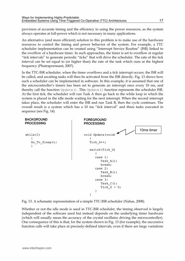
In the TTC-ISR scheduler, when the timer overflows and a tick interrupt occurs, the ISR will be called, and awaiting tasks will then be activated from the ISR directly. Fig. 13 shows how such a scheduler can be implemented in software. In this example, it is assumed that one of the microcontroller’s timers has been set to generate an interrupt once every 10 ms, and
thereby call the function Update(). This Update() function represents the scheduler ISR. At the first tick, the scheduler will run Task A then go back to the while loop in which the system is placed in the idle mode waiting for the next interrupt. When the second interrupt takes place, the scheduler will enter the ISR and run Task B, then the cycle continues. The overall result is a system which has a 10 ms “tick interval” and three tasks executed in sequence (see Fig. 14)
while(1)
{
Go_To_Sleep();
}
BACKGROUND
PROCESSINGFOREGROUND
PROCESSING
void Update(void)
{
Tick_G++;
switch(Tick_G)
{
case 1:
Task_A();
break;
case 2:
Task_B();
break;
case 3:
Task_C();
Tick_G = 0;
}
}
10ms timer
while(1)
{
Go_To_Sleep();
}
BACKGROUND
PROCESSINGFOREGROUND
PROCESSING
void Update(void)
{
Tick_G++;
switch(Tick_G)
{
case 1:
Task_A();
break;
case 2:
Task_B();
break;
case 3:
Task_C();
Tick_G = 0;
}
}
10ms timer
Fig. 13. A schematic representation of a simple TTC-ISR scheduler (Nahas, 2008).
Whether or not the idle mode is used in TTC-ISR scheduler, the timing observed is largely independent of the software used but instead depends on the underlying timer hardware (which will usually mean the accuracy of the crystal oscillator driving the microcontroller). One consequence of this is that, for the system shown in Fig. 13 (for example), the successive function calls will take place at precisely-defined intervals, even if there are large variations
www.intechopen.com
Embedded Systems – Theory and Design Methodology
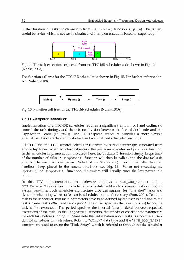
18
in the duration of tasks which are run from the Update()function (Fig. 14). This is very useful behavior which is not easily obtained with implementations based on super loop.
C
Tick interval
TimeTick 0 Tick 1
BIdle
mode
Tick 2
A
Major
cycle
Tick 3
Fig. 14: The task executions expected from the TTC-ISR scheduler code shown in Fig. 13 (Nahas, 2008).
The function call tree for the TTC-ISR scheduler is shown in Fig. 15. For further information, see (Nahas, 2008).
Main () Sleep ()Task ()Update ()
Fig. 15: Function call tree for the TTC-ISR scheduler (Nahas, 2008).
7.3 TTC-dispatch scheduler
Implementation of a TTC-ISR scheduler requires a significant amount of hand coding (to control the task timing), and there is no division between the “scheduler” code and the “application” code (i.e. tasks). The TTC-Dispatch scheduler provides a more flexible alternative. It is characterized by distinct and well-defined scheduler functions.
Like TTC-ISR, the TTC-Dispatch scheduler is driven by periodic interrupts generated from
an on-chip timer. When an interrupt occurs, the processor executes an Update() function. In the scheduler implementation discussed here, the Update() function simply keeps track of the number of ticks. A Dispatch() function will then be called, and the due tasks (if any) will be executed one-by-one. Note that the Dispatch() function is called from an “endless” loop placed in the function Main(): see Fig. 16. When not executing the Update() or Dispatch() functions, the system will usually enter the low-power idle mode.
In this TTC implementation, the software employs a SCH_Add_Task() and a SCH_Delete_Task() functions to help the scheduler add and/or remove tasks during the system run-time. Such scheduler architecture provides support for “one shot” tasks and dynamic scheduling where tasks can be scheduled online if necessary (Pont, 2001). To add a task to the scheduler, two main parameters have to be defined by the user in addition to the task’s name: task’s offset, and task’s period. The offset specifies the time (in ticks) before the task is first executed. The period specifies the interval (also in ticks) between repeated executions of the task. In the Dispatch() function, the scheduler checks these parameters for each task before running it. Please note that information about tasks is stored in a user-
defined scheduler data structure. Both the “sTask” data type and the “SCH_MAX_TASKS” constant are used to create the “Task Array” which is referred to throughout the scheduler
www.intechopen.com
Ways for Implementing Highly-Predictable Embedded Systems Using Time-Triggered Co-Operative (TTC) Architectures
19
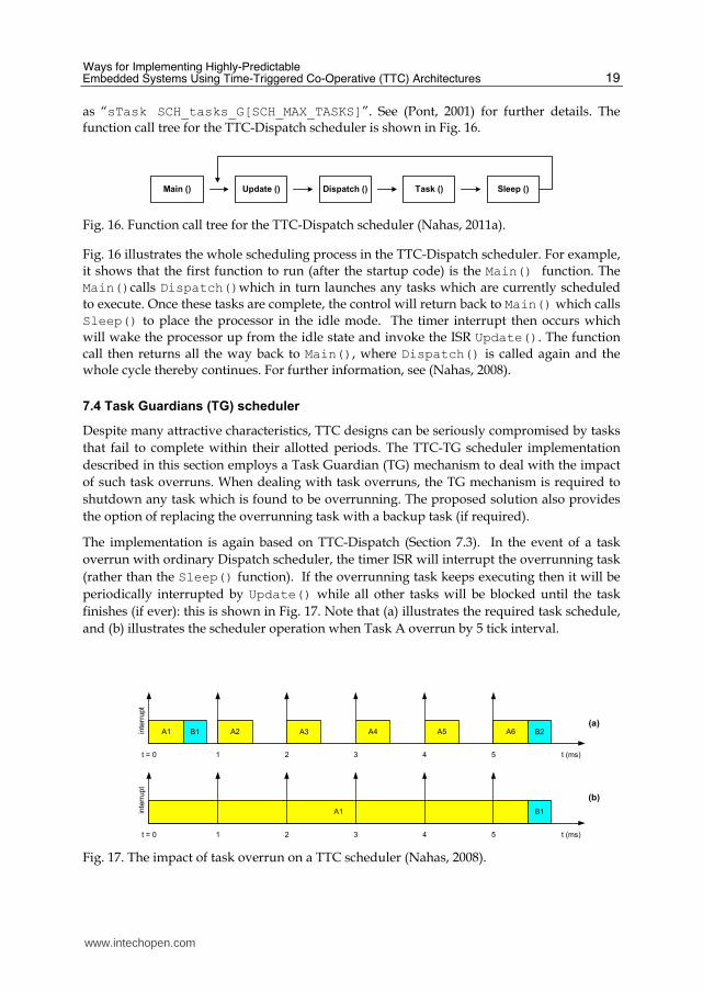
as “sTask SCH_tasks_G[SCH_MAX_TASKS]”. See (Pont, 2001) for further details. The function call tree for the TTC-Dispatch scheduler is shown in Fig. 16.
Main () Sleep ()Task ()Dispatch ()Update ()
Fig. 16. Function call tree for the TTC-Dispatch scheduler (Nahas, 2011a).
Fig. 16 illustrates the whole scheduling process in the TTC-Dispatch scheduler. For example, it shows that the first function to run (after the startup code) is the Main() function. The Main()calls Dispatch()which in turn launches any tasks which are currently scheduled to execute. Once these tasks are complete, the control will return back to Main() which calls
Sleep() to place the processor in the idle mode. The timer interrupt then occurs which will wake the processor up from the idle state and invoke the ISR Update(). The function call then returns all the way back to Main(), where Dispatch() is called again and the whole cycle thereby continues. For further information, see (Nahas, 2008).
7.4 Task Guardians (TG) scheduler
Despite many attractive characteristics, TTC designs can be seriously compromised by tasks
that fail to complete within their allotted periods. The TTC-TG scheduler implementation
described in this section employs a Task Guardian (TG) mechanism to deal with the impact
of such task overruns. When dealing with task overruns, the TG mechanism is required to
shutdown any task which is found to be overrunning. The proposed solution also provides
the option of replacing the overrunning task with a backup task (if required).
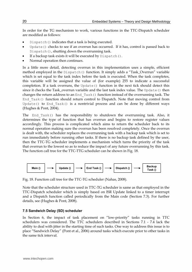
The implementation is again based on TTC-Dispatch (Section 7.3). In the event of a task
overrun with ordinary Dispatch scheduler, the timer ISR will interrupt the overrunning task
(rather than the Sleep() function). If the overrunning task keeps executing then it will be
periodically interrupted by Update() while all other tasks will be blocked until the task
finishes (if ever): this is shown in Fig. 17. Note that (a) illustrates the required task schedule,
and (b) illustrates the scheduler operation when Task A overrun by 5 tick interval.
A1 B1 A2 A3 A4 A5 A6 B2
t = 0 1 2 3 4 5 t (ms)
inte
rrupt
A1 B1inte
rrupt
(a)
(b)
t = 0 1 2 3 4 5 t (ms)
Fig. 17. The impact of task overrun on a TTC scheduler (Nahas, 2008).
www.intechopen.com
Embedded Systems – Theory and Design Methodology
20
In order for the TG mechanism to work, various functions in the TTC-Dispatch scheduler are modified as follows:
Dispatch() indicates that a task is being executed.
Update() checks to see if an overrun has occurred. If it has, control is passed back to
Dispatch(), shutting down the overrunning task.
If a backup task exists it will be executed by Dispatch().
Normal operation then continues.
In a little more detail, detecting overrun in this implementation uses a simple, efficient
method employed in the Dispatch() function. It simply adds a “Task_Overrun” variable which is set equal to the task index before the task is executed. When the task completes, this variable will be assigned the value of (for example) 255 to indicate a successful
completion. If a task overruns, the Update() function in the next tick should detect this since it checks the Task_overrun variable and the last task index value. The Update() then changes the return address to an End_Task() function instead of the overrunning task. The End_Task() function should return control to Dispatch. Note that moving control from Update() to End_Task() is a nontrivial process and can be done by different ways (Hughes & Pont, 2004).
The End_Task() has the responsibility to shutdown the overrunning task. Also, it determines the type of function that has overrun and begins to restore register values accordingly. This process is complicated which aims to return the scheduler back to its normal operation making sure the overrun has been resolved completely. Once the overrun is dealt with, the scheduler replaces the overrunning task with a backup task which is set to run immediately before running other tasks. If there is no backup task defined by the user, then the TTC-TG scheduler implements a mechanism which turns the priority of the task that overrun to the lowest so as to reduce the impact of any future overrunning by this task. The function call tree for the TTC-TTG scheduler can be shown in Fig. 18.
Main ()Backup
Task ()Dispatch ()End Task ()Update ()
Fig. 18. Function call tree for the TTC-TG scheduler (Nahas, 2008).
Note that the scheduler structure used in TTC-TG scheduler is same as that employed in the TTC-Dispatch scheduler which is simply based on ISR Update linked to a timer interrupt and a Dispatch function called periodically from the Main code (Section 7.3). For further details, see (Hughes & Pont, 2008).
7.5 Sandwich Delay (SD) scheduler
In Section 6, the impact of task placement on “low-priority” tasks running in TTC schedulers was considered. The TTC schedulers described in Sections 7.1 - 7.4 lack the ability to deal with jitter in the starting time of such tasks. One way to address this issue is to place “Sandwich Delay” (Pont et al., 2006) around tasks which execute prior to other tasks in the same tick interval.
www.intechopen.com
Ways for Implementing Highly-Predictable Embedded Systems Using Time-Triggered Co-Operative (TTC) Architectures
21
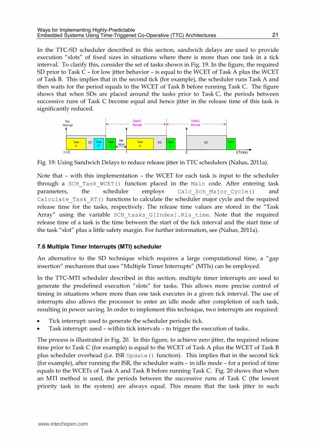
In the TTC-SD scheduler described in this section, sandwich delays are used to provide execution “slots” of fixed sizes in situations where there is more than one task in a tick interval. To clarify this, consider the set of tasks shown in Fig. 19. In the figure, the required SD prior to Task C – for low jitter behavior – is equal to the WCET of Task A plus the WCET of Task B. This implies that in the second tick (for example), the scheduler runs Task A and then waits for the period equals to the WCET of Task B before running Task C. The figure shows that when SDs are placed around the tasks prior to Task C, the periods between successive runs of Task C become equal and hence jitter in the release time of this task is significantly reduced.
Task
A
Task
C
Task C
Period
Task
C
Task
B
t (Ticks)t = 0 1 2
Task C
Period
Task
C
Tick
Interrupt
Idle
ModeSD SD SDTask
A
Fig. 19: Using Sandwich Delays to reduce release jitter in TTC schedulers (Nahas, 2011a).
Note that – with this implementation – the WCET for each task is input to the scheduler
through a SCH_Task_WCET() function placed in the Main code. After entering task
parameters, the scheduler employs Calc_Sch_Major_Cycle() and
Calculate_Task_RT() functions to calculate the scheduler major cycle and the required
release time for the tasks, respectively. The release time values are stored in the “Task
Array” using the variable SCH_tasks_G[Index].Rls_time. Note that the required
release time of a task is the time between the start of the tick interval and the start time of
the task “slot” plus a little safety margin. For further information, see (Nahas, 2011a).
7.6 Multiple Timer Interrupts (MTI) scheduler
An alternative to the SD technique which requires a large computational time, a “gap
insertion” mechanism that uses “Multiple Timer Interrupts” (MTIs) can be employed.
In the TTC-MTI scheduler described in this section, multiple timer interrupts are used to
generate the predefined execution “slots” for tasks. This allows more precise control of
timing in situations where more than one task executes in a given tick interval. The use of
interrupts also allows the processor to enter an idle mode after completion of each task,
resulting in power saving. In order to implement this technique, two interrupts are required:
Tick interrupt: used to generate the scheduler periodic tick.
Task interrupt: used – within tick intervals – to trigger the execution of tasks.
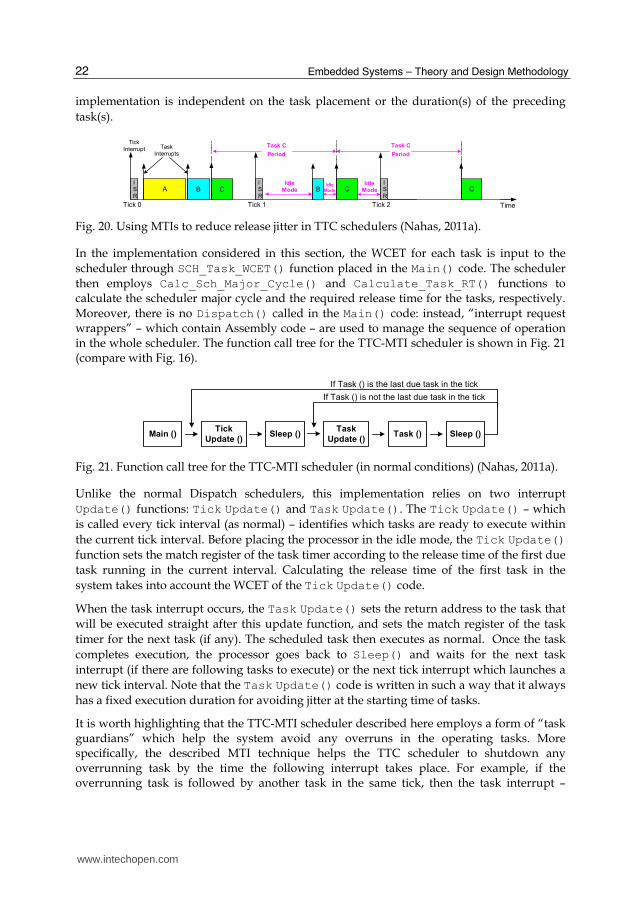
The process is illustrated in Fig. 20. In this figure, to achieve zero jitter, the required release
time prior to Task C (for example) is equal to the WCET of Task A plus the WCET of Task B
plus scheduler overhead (i.e. ISR Update() function). This implies that in the second tick
(for example), after running the ISR, the scheduler waits – in idle mode – for a period of time
equals to the WCETs of Task A and Task B before running Task C. Fig. 20 shows that when
an MTI method is used, the periods between the successive runs of Task C (the lowest
priority task in the system) are always equal. This means that the task jitter in such
www.intechopen.com
Embedded Systems – Theory and Design Methodology
22
implementation is independent on the task placement or the duration(s) of the preceding
task(s).
A C
Task C
Period
CB B
TimeTick 0 Tick 1 Tick 2
Task C
Period
C
Tick
Interrupt Task
Interrupts
IdleMode
Idle
Mode
IS
R
IS
R
IS
R
Idle
Mode
Fig. 20. Using MTIs to reduce release jitter in TTC schedulers (Nahas, 2011a).
In the implementation considered in this section, the WCET for each task is input to the
scheduler through SCH_Task_WCET() function placed in the Main() code. The scheduler then employs Calc_Sch_Major_Cycle() and Calculate_Task_RT() functions to calculate the scheduler major cycle and the required release time for the tasks, respectively. Moreover, there is no Dispatch() called in the Main() code: instead, “interrupt request wrappers” – which contain Assembly code – are used to manage the sequence of operation in the whole scheduler. The function call tree for the TTC-MTI scheduler is shown in Fig. 21 (compare with Fig. 16).
Main ()Tick
Update ()Sleep ()
Task
Update ()Task () Sleep ()
If Task () is not the last due task in the tick
If Task () is the last due task in the tick
Fig. 21. Function call tree for the TTC-MTI scheduler (in normal conditions) (Nahas, 2011a).
Unlike the normal Dispatch schedulers, this implementation relies on two interrupt
Update() functions: Tick Update() and Task Update(). The Tick Update() – which
is called every tick interval (as normal) – identifies which tasks are ready to execute within
the current tick interval. Before placing the processor in the idle mode, the Tick Update()
function sets the match register of the task timer according to the release time of the first due
task running in the current interval. Calculating the release time of the first task in the
system takes into account the WCET of the Tick Update() code.
When the task interrupt occurs, the Task Update() sets the return address to the task that
will be executed straight after this update function, and sets the match register of the task
timer for the next task (if any). The scheduled task then executes as normal. Once the task
completes execution, the processor goes back to Sleep() and waits for the next task
interrupt (if there are following tasks to execute) or the next tick interrupt which launches a
new tick interval. Note that the Task Update() code is written in such a way that it always
has a fixed execution duration for avoiding jitter at the starting time of tasks.
It is worth highlighting that the TTC-MTI scheduler described here employs a form of “task guardians” which help the system avoid any overruns in the operating tasks. More specifically, the described MTI technique helps the TTC scheduler to shutdown any overrunning task by the time the following interrupt takes place. For example, if the overrunning task is followed by another task in the same tick, then the task interrupt –
www.intechopen.com
Ways for Implementing Highly-Predictable Embedded Systems Using Time-Triggered Co-Operative (TTC) Architectures
23
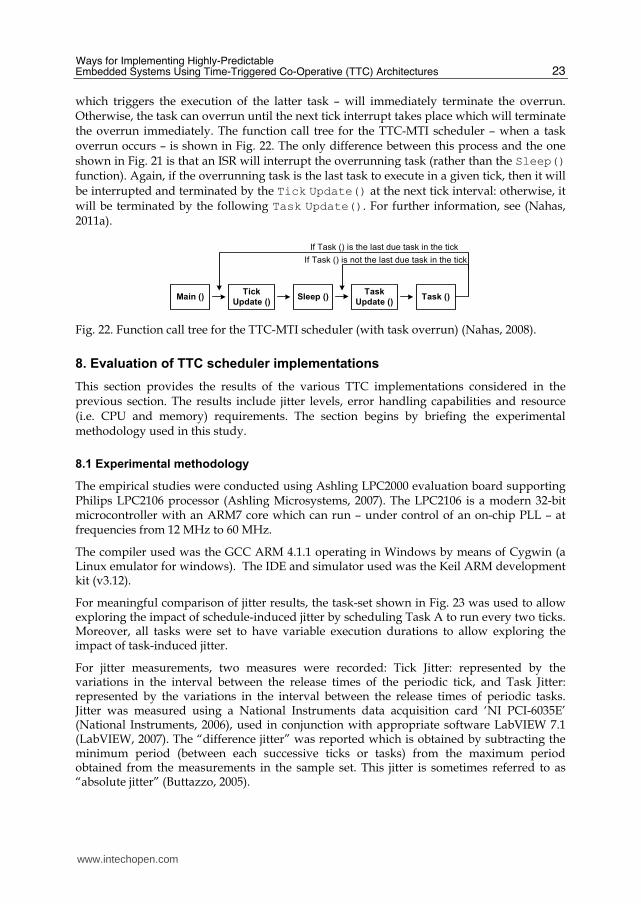
which triggers the execution of the latter task – will immediately terminate the overrun. Otherwise, the task can overrun until the next tick interrupt takes place which will terminate the overrun immediately. The function call tree for the TTC-MTI scheduler – when a task overrun occurs – is shown in Fig. 22. The only difference between this process and the one shown in Fig. 21 is that an ISR will interrupt the overrunning task (rather than the Sleep() function). Again, if the overrunning task is the last task to execute in a given tick, then it will
be interrupted and terminated by the Tick Update() at the next tick interval: otherwise, it will be terminated by the following Task Update(). For further information, see (Nahas, 2011a).
Main ()Tick
Update ()Sleep ()
Task
Update ()Task ()
If Task () is not the last due task in the tick
If Task () is the last due task in the tick
Fig. 22. Function call tree for the TTC-MTI scheduler (with task overrun) (Nahas, 2008).
8. Evaluation of TTC scheduler implementations
This section provides the results of the various TTC implementations considered in the previous section. The results include jitter levels, error handling capabilities and resource (i.e. CPU and memory) requirements. The section begins by briefing the experimental methodology used in this study.
8.1 Experimental methodology
The empirical studies were conducted using Ashling LPC2000 evaluation board supporting Philips LPC2106 processor (Ashling Microsystems, 2007). The LPC2106 is a modern 32-bit microcontroller with an ARM7 core which can run – under control of an on-chip PLL – at frequencies from 12 MHz to 60 MHz.
The compiler used was the GCC ARM 4.1.1 operating in Windows by means of Cygwin (a Linux emulator for windows). The IDE and simulator used was the Keil ARM development kit (v3.12).
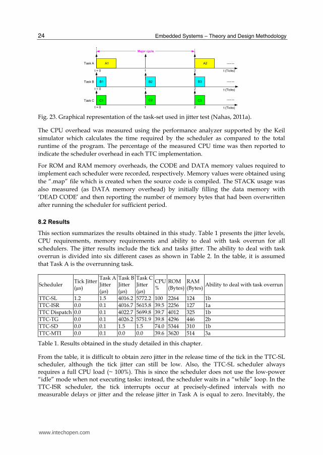
For meaningful comparison of jitter results, the task-set shown in Fig. 23 was used to allow exploring the impact of schedule-induced jitter by scheduling Task A to run every two ticks. Moreover, all tasks were set to have variable execution durations to allow exploring the impact of task-induced jitter.
For jitter measurements, two measures were recorded: Tick Jitter: represented by the variations in the interval between the release times of the periodic tick, and Task Jitter: represented by the variations in the interval between the release times of periodic tasks. Jitter was measured using a National Instruments data acquisition card ‘NI PCI-6035E’ (National Instruments, 2006), used in conjunction with appropriate software LabVIEW 7.1 (LabVIEW, 2007). The “difference jitter” was reported which is obtained by subtracting the minimum period (between each successive ticks or tasks) from the maximum period obtained from the measurements in the sample set. This jitter is sometimes referred to as “absolute jitter” (Buttazzo, 2005).
www.intechopen.com
Embedded Systems – Theory and Design Methodology
24
B1
A1
B2
C1
t = 0 1
C2
t = 0 1
t (Ticks)t = 0 1
Task A
Task B
Task C
t (Ticks)
t (Ticks)
Major cycle
B3
A2
C3
2
2
2
Fig. 23. Graphical representation of the task-set used in jitter test (Nahas, 2011a).
The CPU overhead was measured using the performance analyzer supported by the Keil
simulator which calculates the time required by the scheduler as compared to the total
runtime of the program. The percentage of the measured CPU time was then reported to
indicate the scheduler overhead in each TTC implementation.
For ROM and RAM memory overheads, the CODE and DATA memory values required to
implement each scheduler were recorded, respectively. Memory values were obtained using
the “.map” file which is created when the source code is compiled. The STACK usage was
also measured (as DATA memory overhead) by initially filling the data memory with
‘DEAD CODE’ and then reporting the number of memory bytes that had been overwritten
after running the scheduler for sufficient period.
8.2 Results
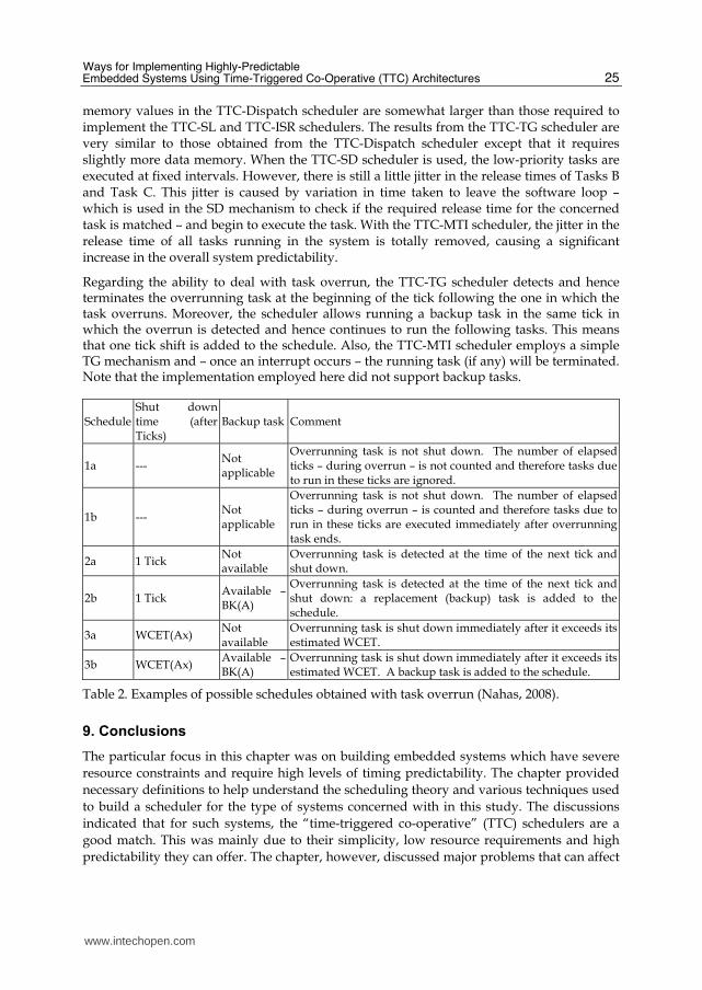
This section summarizes the results obtained in this study. Table 1 presents the jitter levels,
CPU requirements, memory requirements and ability to deal with task overrun for all
schedulers. The jitter results include the tick and tasks jitter. The ability to deal with task
overrun is divided into six different cases as shown in Table 2. In the table, it is assumed
that Task A is the overrunning task.
Scheduler Tick Jitter(µs)
Task AJitter (µs)
Task BJitter (µs)
Task CJitter (µs)
CPU%
ROM (Bytes)
RAM (Bytes)
Ability to deal with task overrun
TTC-SL 1.2 1.5 4016.2 5772.2 100 2264 124 1b
TTC-ISR 0.0 0.1 4016.7 5615.8 39.5 2256 127 1a
TTC Dispatch 0.0 0.1 4022.7 5699.8 39.7 4012 325 1b
TTC-TG 0.0 0.1 4026.2 5751.9 39.8 4296 446 2b
TTC-SD 0.0 0.1 1.5 1.5 74.0 5344 310 1b
TTC-MTI 0.0 0.1 0.0 0.0 39.6 3620 514 3a
Table 1. Results obtained in the study detailed in this chapter.
From the table, it is difficult to obtain zero jitter in the release time of the tick in the TTC-SL scheduler, although the tick jitter can still be low. Also, the TTC-SL scheduler always requires a full CPU load (~ 100%). This is since the scheduler does not use the low-power “idle” mode when not executing tasks: instead, the scheduler waits in a “while” loop. In the TTC-ISR scheduler, the tick interrupts occur at precisely-defined intervals with no measurable delays or jitter and the release jitter in Task A is equal to zero. Inevitably, the
www.intechopen.com
Ways for Implementing Highly-Predictable Embedded Systems Using Time-Triggered Co-Operative (TTC) Architectures
25
memory values in the TTC-Dispatch scheduler are somewhat larger than those required to implement the TTC-SL and TTC-ISR schedulers. The results from the TTC-TG scheduler are very similar to those obtained from the TTC-Dispatch scheduler except that it requires slightly more data memory. When the TTC-SD scheduler is used, the low-priority tasks are executed at fixed intervals. However, there is still a little jitter in the release times of Tasks B and Task C. This jitter is caused by variation in time taken to leave the software loop – which is used in the SD mechanism to check if the required release time for the concerned task is matched – and begin to execute the task. With the TTC-MTI scheduler, the jitter in the release time of all tasks running in the system is totally removed, causing a significant increase in the overall system predictability.
Regarding the ability to deal with task overrun, the TTC-TG scheduler detects and hence terminates the overrunning task at the beginning of the tick following the one in which the task overruns. Moreover, the scheduler allows running a backup task in the same tick in which the overrun is detected and hence continues to run the following tasks. This means that one tick shift is added to the schedule. Also, the TTC-MTI scheduler employs a simple TG mechanism and – once an interrupt occurs – the running task (if any) will be terminated. Note that the implementation employed here did not support backup tasks.
Schedule Shut down time (after Ticks)
Backup task Comment
1a --- Not applicable
Overrunning task is not shut down. The number of elapsed ticks – during overrun – is not counted and therefore tasks due to run in these ticks are ignored.
1b --- Not applicable
Overrunning task is not shut down. The number of elapsed ticks – during overrun – is counted and therefore tasks due to run in these ticks are executed immediately after overrunning task ends.
2a 1 Tick Not available
Overrunning task is detected at the time of the next tick and shut down.
2b 1 Tick Available –BK(A)
Overrunning task is detected at the time of the next tick and shut down: a replacement (backup) task is added to the schedule.
3a WCET(Ax) Not available
Overrunning task is shut down immediately after it exceeds its estimated WCET.
3b WCET(Ax) Available –BK(A)
Overrunning task is shut down immediately after it exceeds its estimated WCET. A backup task is added to the schedule.
Table 2. Examples of possible schedules obtained with task overrun (Nahas, 2008).
9. Conclusions
The particular focus in this chapter was on building embedded systems which have severe
resource constraints and require high levels of timing predictability. The chapter provided
necessary definitions to help understand the scheduling theory and various techniques used
to build a scheduler for the type of systems concerned with in this study. The discussions
indicated that for such systems, the “time-triggered co-operative” (TTC) schedulers are a
good match. This was mainly due to their simplicity, low resource requirements and high
predictability they can offer. The chapter, however, discussed major problems that can affect
www.intechopen.com
Embedded Systems – Theory and Design Methodology
26
the performance of TTC schedulers and reviewed some suggested solutions to overcome
such problems.
Then, the discussions focused on the relationship between scheduling algorithm and scheduler implementations and highlighted the challenges faced when implementing software for a particular scheduler. It was clearly noted that such challenges were mainly caused by the broad range of possible implementation options a scheduler can have in practice, and the impact of such implementations on the overall system behavior.
The chapter then reviewed six various TTC scheduler implementations that can be used for resource-constrained embedded systems with highly-predictable system behavior. Useful results from the described schedulers were then provided which included jitter levels, memory requirements and error handling capabilities. The results suggested that a “one size fits all” TTC implementation does not exist in practice, since each implementation has advantages and disadvantages. The selection of a particular implementation will, hence, be decided based on the requirements of the application in which the TTC scheduler is employed, e.g. timing and resource requirements.
10. Acknowledgement
The research presented in this chapter was mainly conducted in the Embedded Systems Laboratory (ESL) at University of Leicester, UK, under the supervision of Professor Michael Pont, to whom the authors are thankful.
11. References
Allworth, S.T. (1981) “An Introduction to Real-Time Software Design”, Macmillan, London. Ashling Microsystems (2007) “LPC2000 Evaluation and Development Kits datasheet”,
available online (Last accessed: November 2010) http://www.ashling.com/pdf_datasheets/DS266-EvKit2000.pdf Avrunin, G.S., Corbett, J.C. and Dillon, L.K. (1998) “Analyzing partially-implemented real-
time systems”, IEEE Transactions on Software Engineering, Vol. 24 (8), pp.602-614. Ayavoo, D. (2006) “The Development of Reliable X-by-Wire Systems: Assessing The
Effectiveness of a ‘Simulation First’ Approach”, PhD thesis, Department of Engineering, University of Leicester, UK.
Ayavoo, D., Pont, M.J. and Parker, S. (2006) “Does a ‘simulation first’ approach reduce the effort involved in the development of distributed embedded control systems?”, 6th UKACC International Control Conference, Glasgow, Scotland, 2006.
Ayavoo, D., Pont, M.J., Short, M. and Parker, S. (2007) "Two novel shared-clock scheduling algorithms for use with CAN-based distributed systems", Microprocessors and Microsystems, Vol. 31(5), pp. 326-334.
Baker, T.P. and Shaw, A. (1989) “The cyclic executive model and Ada. Real-Time Systems”, Vol. 1 (1), pp. 7-25.
Bannatyne, R. (1998) “Time triggered protocol-fault tolerant serial communications for real-time embedded systems”, WESCON/98 Conference Proceedings, Anaheim, CA, USA, pp. 86-91.
Barr, M. (1999) “Programming Embedded Systems in C and C++”, O'Reilly Media.
www.intechopen.com
Ways for Implementing Highly-Predictable Embedded Systems Using Time-Triggered Co-Operative (TTC) Architectures
27
Baruah S.K. (2006) “The Non-preemptive Scheduling of Periodic Tasks upon Multiprocessors”, Real-Time Systems, Vol. 32, pp. 9-20.
Bate, I.J. (1998), “Scheduling and Timing Analysis for Safety Critical Real-Time Systems”, PhD thesis, Department of Computer Science, University of York.
Bates, I. (2000) “Introduction to scheduling and timing analysis”, in The Use of Ada in Real-Time System, IEE Conference Publication 00/034.
Bolton, W. (2000) “Microprocessor Systems”, Longman. Buttazzo, G. (2005), “Hard real-time computing systems: predictable scheduling algorithms
and applications”, Second Edition, Springer. Cho, Y., Yoo, S., Choi, K., Zergainoh, N.E. and Jerraya, A. (2005) “Scheduler implementation
in MPSoC Design”, In: Asia South Pacific Design Automation Conference (ASPDAC’05), pp. 151-156.
Cho, Y., Zergainoh, N-E., Yoo, S., Jerraya, A.A. and Choi, K. (2007) “Scheduling with accurate communication delay model and scheduler implementation for multiprocessor system-on-chip”, Design Automation for Embedded Systems, Vol. 11 (2-3), pp. 167-191.
Cooling, J.E. (1991) “Software design for real time systems”, Chapman and Hall. Cottet, F. (2002) “Scheduling in Real-time Systems”, Wiley. Fisher, J.A., Faraboschi, P. and Young, C. (2004) “Embedded Computing: A VLIW Approach
to Architecture, Compilers and Tools”, Morgan Kaufmann. Hsieh, C-C. and Hsu, P-L. (2005) “The event-triggered network control structure for CAN-
based motion system”,Proceeding of the 2005 IEEE conference on Control Applications, Toronto, Canada, August 28 – 31, 2005.
Hughes, Z.M. and Pont, M.J. (2008) “Reducing the impact of task overruns in resource-constrained embedded systems in which a time-triggered software architecture is employed”, Trans Institute of Measurement and Control.
Jerri, A.J. (1977), “The Shannon sampling theorem: its various extensions and applications a tutorial review”, Proc. of the IEEE, Vol. 65, pp. 1565-1596.
Kalinsky, D. (2001) “ Context switch, Embedded Systems Programming”, Vol. 14(1), 94-105. Kamal, R. (2003) “Embedded Systems: Architecture, Programming and Design”, McGraw-
Hill. Katcher, D., Arakawa, H. and Strosnider, J. (1993) “Engineering and analysis of fixed
priority schedulers”, IEEE Transactions on Software Engineering, Vol. 19 (9), pp. 920-934.
Kim, N., Ryu, M., Hong, S. and Shin, H. (1999) “Experimental Assessment of the Period Calibration Method: A Case Study”, Real-Time Systems, Vol. 17 (1), pp. 41-64.
Koch, B. (1999) “The Theory of Task Scheduling in Real-Time Systems: Compilation and Systematization of the Main Results”, Studies thesis, University of Hamburg.
Konrad, S., Cheng, B.H. C. and Campbell, L.A. (2004) “Object analysis patterns for embedded systems”, IEEE Transactions on Software Engineering, Vol. 30 (12), pp. 970- 992.
Kopetz, H. (1991a) “Event-triggered versus time-triggered real-time systems”, In: Proceedings of the InternationalWorkshop on Operating Systems of the 90s and Beyond, London, UK, Springer-Verlag, pp. 87-101.
Kopetz, H. (1991b), “Event-triggered versus time-triggered real-time systems”, Technical Report 8/91, Technical University of Vienna, Austria.
www.intechopen.com
Embedded Systems – Theory and Design Methodology
28
Kopetz, H. (1997) “Real-time systems: Design principles for distributed embedded applications”, Kluwer Academic.
Kurian, S. and Pont, M.J. (2007) “Maintenance and evolution of resource-constrained embedded systems created using design patterns”, Journal of Systems and Software, Vol. 80 (1), pp. 32-41.
LabVIEW (2007) “LabVIEW 7.1 Documentation Resources”, WWW website (Last accessed: November 2010) http://digital.ni.com/public.nsf/allkb/06572E936282C0E486256EB0006B70B4
Leung J.Y.T. and Whitehead, J. (1982) “On the Complexity of Fixed-Priority Scheduling of Periodic Real-Time Tasks”, Performance Evaluation, Vol. 2, pp. 237-250.
Liu, C.L. and Layland, J.W. (1973), “Scheduling algorithms for multi-programming in a hard real-time environment”, Journal of the AVM 20, Vol. 1, pp. 40-61.
Liu, J.W.S. (2000), “Real-time systems”, Prentice Hall. Locke, C.D. (1992), “Software architecture for hard real-time applications: cyclic executives
vs. fixed priority executives”, Real-Time Systems, Vol. 4, pp. 37-52. Maaita, A. and Pont, M.J. (2005) “Using 'planned pre-emption' to reduce levels of task jitter
in a time-triggered hybrid scheduler”. In: Koelmans, A., Bystrov, A., Pont, M.J., Ong, R. and Brown, A. (Eds.), Proceedings of the Second UK Embedded Forum (Birmingham, UK, October 2005), pp. 18-35. Published by University of Newcastle upon Tyne
Marti, P. (2002), “Analysis and design of real-time control systems with varying control timing constraints”, PhD thesis, Automatic Control Department, Technical University of Catalonia.
Marti, P., Fuertes, J.M., Villa, R. and Fohler, G. (2001), “On Real-Time Control Tasks Schedulability”, European Control Conference (ECC01), Porto, Portugal, pp. 2227-2232.
Mok, A.K. (1983) “Fundamental Design Problems of Distributed Systems for the Hard Real-Time Environment”, Ph.D Thesis, MIT, USA.
Mwelwa, C. (2006) “Development and Assessment of a Tool to Support Pattern-Based Code Generation of Time-Triggered (TT) Embedded Systems”, PhD thesis, Department of Engineering, University of Leicester, UK.
Mwelwa, C., Athaide, K., Mearns, D., Pont, M.J. and Ward, D. (2006) “Rapid software development for reliable embedded systems using a pattern-based code generation tool”, Paper presented at the Society of Automotive Engineers (SAE) World Congress, Detroit, Michigan, USA, April 2006. SAE document number: 2006-01-1457. Appears in: Society of Automotive Engineers (Ed.) “In-vehicle software and hardware systems”, Published by Society of Automotive Engineers.
Nahas, M. (2008) “Bridging the gap between scheduling algorithms and scheduler implementations in time-triggered embedded systems”, PhD thesis, Department of Engineering, University of Leicester, UK.
Nahas, M. (2011a) "Employing two ‘sandwich delay’ mechanisms to enhance predictability of embedded systems which use time-triggered co-operative architectures", International Journal of Software Engineering and Applications, Vol. 4, No. 7, pp. 417-425
www.intechopen.com
Ways for Implementing Highly-Predictable Embedded Systems Using Time-Triggered Co-Operative (TTC) Architectures
29
Nahas, M. (2011b) "Implementation of highly-predictable time-triggered cooperative scheduler using simple super loop architecture", International Journal of Electrical and Computer Sciences,Vol. 11, No. 4, pp. 33-38.
National Instruments (2006) “Low-Cost E Series Multifunction DAQ – 12 or 16-Bit, 200 kS/s, 16 Analog Inputs”, available online (Last accessed: November 2010) http://www.ni.com/pdf/products/us/4daqsc202-204_ETC_212-213.pdf
Nghiem, T., Pappas, G.J., Alur, R. and Girard, A. (2006) “Time-triggered implementations of dynamic controllers”, Proceedings of the 6th ACM & IEEE International conference on Embedded software, Seoul, Korea, pp. 2-11.
Nissanke, N. (1997) “Real-time Systems”, Prentice-Hall. Obermaisser, R (2004) “Event-Triggered and Time-Triggered Control Paradigms”, Kluwer
Academic. Phatrapornnant, T. (2007) “Reducing Jitter in Embedded Systems Employing a Time-
Triggered Software Architecture and Dynamic Voltage Scaling”, PhD thesis, Department of Engineering, University of Leicester, UK.
Phatrapornnant, T. and Pont, M.J. (2004) “The application of dynamic voltage scaling in embedded systems employing a TTCS software architecture: A case study”, Proceedings of the IEE / ACM Postgraduate Seminar on “System-On-Chip Design, Test and Technology”, Loughborough, UK, 15 September 2004. Published by IEE. ISBN: 0 86341 460 5 (ISSN: 0537-9989), pp. 3-8.
Phatrapornnant, T. and Pont, M.J. (2006), “Reducing jitter in embedded systems employing a time-triggered software architecture and dynamic voltage scaling”, IEEE Transactions on Computers, Vol. 55 (2), pp. 113-124.
Pont, M.J. (2001) “Patterns for time-triggered embedded systems: Building reliable applications with the 8051 family of microcontrollers”, ACM Press / Addison-Wesley.
Pont, M.J. (2002) “Embedded C”, Addison-Wesley. Pont, M.J., Kurian, S. and Bautista-Quintero, R. (2006) “Meeting real-time constraints using
‘Sandwich Delays’”, In: Zdun, U. and Hvatum, L. (Eds) Proceedings of the Eleventh European conference on Pattern Languages of Programs (EuroPLoP '06), Germany, July 2006: pp. 67-77. Published by Universitätsverlag Konstanz.
Pont, M.J., Kurian, S., Wang, H. and Phatrapornnant, T. (2007) “Selecting an appropriate scheduler for use with time-triggered embedded systems”, Paper presented at the twelfth European Conference on Pattern Languages of Programs (EuroPLoP 2007).
Pop et al., 2002 Pop, P., Eles, P. and Peng, Z. (2004) “Analysis and Synthesis of Distributed Real-Time
Embedded Systems”, Springer. Profeta III, J.A., Andrianos, N.P., Bing, Yu, Johnson, B.W., DeLong, T.A., Guaspart, D. and
Jamsck, D. (1996) “Safety-critical systems built with COTS”, IEEE Computer, Vol. 29 (11), pp. 54-60.
Rao, M.V.P, Shet, K.C, Balakrishna, R. and Roopa, K. (2008) “Development of Scheduler for Real Time and Embedded System Domain”, 22nd International Conference on Advanced Information Networking and Applications - Workshops, 25-28 March 2008, AINAW, pp. 1-6.
Redmill, F. (1992) “Computers in safety-critical applications”, Computing & Control Engineering Journal, Vol. 3 (4), pp.178-182.
www.intechopen.com
Embedded Systems – Theory and Design Methodology
30
Sachitanand, N.N. (2002). “Embedded systems - A new high growth area”. The Hindu. Bangalore.
Scheler, F. and Schröder-Preikschat, W. (2006) “Time-Triggered vs. Event-Triggered: A matter of configuration?”, GI/ITG Workshop on Non-Functional Properties of Embedded Systems (NFPES), March 27 – 29, 2006, Nürnberg, Germany.
Sommerville, I. (2007) “Software engineering”, 8th edition, Harlow: Addison-Wesley. Stankovic, J.A. (1988) “Misconceptions about real-time computing”, IEEE Computers, Vol.
21 (10). Storey, N. (1996) “Safety-critical computer systems”, Harlow, Addison-Wesley. Torngren, M. (1998), “Fundamentals of implementing real-time control applications in
distributed computer systems”, Real-Time Systems, Vol. 14, pp. 219-250. Ward, N.J. (1991) “The static analysis of a safety-critical avionics control systems”, Air
Transport safety: Proceedings of the Safety and Reliability Society Spring Conference, In: Corbyn D.E. and Bray, N.P. (Eds.)
Wavecrest (2001), “Understanding Jitter: Getting Started”, Wavecrest Corporation. Xu , J. and Parnas, D.L. (1993) “On satisfying timing constraints in hard - real - time
systems”, IEEE Transactions on Software Engineering, Vol. 19 (1), pp. 70-84.
www.intechopen.com
Embedded Systems - Theory and Design MethodologyEdited by Dr. Kiyofumi Tanaka
ISBN 978-953-51-0167-3Hard cover, 430 pagesPublisher InTechPublished online 02, March, 2012Published in print edition March, 2012
InTech EuropeUniversity Campus STeP Ri Slavka Krautzeka 83/A 51000 Rijeka, Croatia Phone: +385 (51) 770 447 Fax: +385 (51) 686 166www.intechopen.com
InTech ChinaUnit 405, Office Block, Hotel Equatorial Shanghai No.65, Yan An Road (West), Shanghai, 200040, China
Phone: +86-21-62489820 Fax: +86-21-62489821
Nowadays, embedded systems - the computer systems that are embedded in various kinds of devices andplay an important role of specific control functions, have permitted various aspects of industry. Therefore, wecan hardly discuss our life and society from now onwards without referring to embedded systems. For wide-ranging embedded systems to continue their growth, a number of high-quality fundamental and appliedresearches are indispensable. This book contains 19 excellent chapters and addresses a wide spectrum ofresearch topics on embedded systems, including basic researches, theoretical studies, and practical work.Embedded systems can be made only after fusing miscellaneous technologies together. Various technologiescondensed in this book will be helpful to researchers and engineers around the world.
How to referenceIn order to correctly reference this scholarly work, feel free to copy and paste the following:
Mouaaz Nahas and Ahmed M. Nahhas (2012). Ways for Implementing Highly-Predictable Embedded SystemsUsing Time-Triggered Co-Operative (TTC) Architectures, Embedded Systems - Theory and DesignMethodology, Dr. Kiyofumi Tanaka (Ed.), ISBN: 978-953-51-0167-3, InTech, Available from:http://www.intechopen.com/books/embedded-systems-theory-and-design-methodology/ways-for-implementing-highly-predictable-embedded-systems-using-time-triggered-co-operative-ttc-arch
© 2012 The Author(s). Licensee IntechOpen. This is an open access articledistributed under the terms of the Creative Commons Attribution 3.0License, which permits unrestricted use, distribution, and reproduction inany medium, provided the original work is properly cited.