volume i rnal report vacuum jacketed composite · pdf filevolume i rnal report vacuum jacketed...
TRANSCRIPT

A CR-134550
Volume I Rnal Report
Vacuum Jacketed Composite PropulsionFeedlines for Cryogenic Launch
and Space Vehicles
by
D. E. Spond, D. J. Laintz, C. A. Hall and D. E. Dulaigh
MARTIN MARIETTA CORPORATION
Prepared for
NATIONAL AERONAUTICS AND SPACE ADMINISTRATION
V X'.W NASA Lewis Research Center
Contract NAS3-16762
Joseph Notardonato, Project Manager
\P . .
I.c-rert . Ju i : - . 1 J72 - ( a a r c i / i :iiristtoP H C . * v : , O C . _ _ CcCi 22. GJ/J1
https://ntrs.nasa.gov/search.jsp?R=19740010392 2018-05-14T19:57:26+00:00Z

U.S. DEPARTMENT OF COMMERCENational Technical Information Service
N74-18505
VACUUM JACKETED COMPOSITEPROPULSION FEEDINES FOR CRYOGENICLAUNCH AND SPACE VEHICLES
NASA LEWIS RESEARCH CENTERCLEVELAND, OH
MAR 84

1. Report No.
NASA CR-1345502. Government Accession No.
4. Title and Subtitle
Vacuum Jacketed Composite Propulsion Feedlines for CryogenicLaunch and Space Vehicles
7. Author(s)
D. E. Spend, D. J. Laintz, C. A . Hall, D. E. Dulaigh
9. Performing Organization Name and Address
Martin Marietta CorporationP. 0. Box 179Denver, Colorado 80201
12. Sponsoring Agency Name and Address
National Aeronautics and Space AdministrationLewis Research CenterCleveland, Ohio 44135
3. Recipient's Catalog No.
5. Report DateMarch 1974
6. Performing Organization Code04236
8. Performing Organization Report No.
10. Work Unit No.
It. Contract or Grant No.
NAS3-16762
13. Type of Report and Period CoveredFinal ReportJune 1972 to August 1973
14. Sponsoring Agency Code
15. Supplementary Notes
16. Abstract
Thin metallic liners that provide leak-free service in cryogenic propulsion systems are over-wrapped with a glass-fiber composite that provides strength and protection from handling dam-age. The resultant tube is lightweight, strong, and has a low thermal flux. The insidecommodity flow line and the outside vacuum jacket were fabricated using this method. Severaltypes of vacuum jackets were fabricated and tested at operating temperatures from 294 to 21 K
. (+70 to -423°F) and operating pressures up to 69 N/cm2 (100 psi). The primary objective ofthe program was to develop vacuum jacket concepts, using previously developed concepts forthe inner line. All major program objectives were met resulting in a design concept that isadaptable to a wide range of aerospace vehicle requirements. Major items of development in-cluded convolution of thin metallic sections up to 46 cm (18 in.) in diameter, design and fab-rication of an extremely lightweight tension membrane concept for the vacuum jacket, and ana-lytical tools that predict the failure mode and levels. An attempt to bond the vacuum jacketliner to the composite overwrap was unsuccessful resulting in the premature failure of severallines. A redesign, which is not dependent upon bonding, was successful. Weight savings ofover 50% are attainable for vacuum jacketed composite feedlines when compared to conventionalconfigurations and materials of construction.
17. Key Words (Suggested by Author (si)
CompositeCryogenic
- Eeedline . . . . . . . .Overwrap
- Vacuum Jacketed Lines - - - - - - - - - - - - -
18. Distribution Statement
Unclassified - Unlimited
19. Security Classif. (of this report) 20. Security Class! f. .(of this page) 21. No. of Pages 22. Price'
Unclassified Unclassified 1 2> 1 ty/£iOC
For sale by the National Technical Information Service. Springfield. Virginia 22151

FOREWORD
The work described herein was conducted by Martin MariettaCorporation, Denver Division, under NASA Contract NAS3-16762,under the management of the NASA Project Manager, Mr. JosephNotardonato, Propulsion Systems Branch, NASA-Lewis ResearchCenter, Cleveland, Ohio.
This final report is published in two volumes: Volume Idescribes the results of the program and Volume II containsrelated appendixes.
In addition to the stated authors, the following personsprovided major assistance: Messrs. Clifford S. Foster, JohnR. Lager, Gary E. Wilson, Stanley R. Tomer, Walter L. McKenna,William E. Mohr, Timothy P. Quinn, Connie E. Lynch, and DonaldA. Stang. Major contributors at the Grumman Aerospace Corpor-ation included Messrs. Michael J. Martin, Benjamin Aleck, andCarlos Cacho-Negrete.
ii

TABLE OF CONTENTS
Vol I
Page
Foreword ................................ iiSymbols .............. .......... ...... . . viiDefinition of Terms . . . . . . . . ..... ....... . ........ xiSummary ................................ xiv
INTRODUCTION . . . .......... ' . . ............... 1
CONCEPTUAL DESIGN ........................... 4
CONCEPT EVALUATION ................ ........... 17
PRELIMINARY TESTING .............. ............ 34
TEST ITEM DESIGN ........... ................. 41
FABRICATION ..... ...... . ................ . . 49
TESTING ..... . .......................... 74
ANALYSIS OF RESULTS ...................... .... 100
RECOMMENDATIONS AND ADDITIONAL WORK REQUIRED .............. 119
SUMMARY OF RESULTS ........................... 121
REFERENCES .................. • ............. 123
DISTRIBUTION LIST ............... ........ .... 124thru135
Vol II
AppendixesA - STRUCTURAL ANALYSIS .............. .......... 1B - THERMAL PERFORMANCE - COMPOSITE VERSUS ALL-METAL INNER LINE FOR
VACUUM JACKETED COMPOSITE LINE ................... 17C - HEAT TRANSFER PERFORMANCE, VACUUM END CLOSURES FOR VACUUM JACKETED
COMPOSITE LINES .......................... 29D - FAILURE ANALYSES - VACUUM JACKETED COMPOSITE LINES COLLAPSE
FAILURE ............... ...... ......... 39E - TENSION MEMBRANE - DETAILED INFORMATION ........ ...... 63
iii

Figure1 Comparison of Overwrap Weight and Cost Per Unit Length Versus
Inner Line Diameter 122 Vacuum Acquisition Port 133 Vacuum Jacketed Composite Line, Concept 1 (O.D. Glass Ribs) ... 144 Vacuum Jacketed Composite Line, Concept 2 (Outside Convolute
Stiffeners) 145 Vacuum Jacketed Composite Line, Concept 3 (Internal Supports
No Convolutes) 156 Vacuum Jacketed Composite Line, Concept 4 (I.D. Convolutes with
External Glass) 157 Vacuum Jacketed Composite Line, Concept 5 (Tension Membrane) . . 168 Circumferential Stiffener Concepts 309 Vacuum Jacket Axial Compression Loading Capability . . . . . . . 3110 Random Vibration Input (Shuttle Launch) . 3211 Vacuum Jacketed Composite Line Weight [42 N/cm2 (60 psi)
Absolute Operating Pressure] . . . . 3312 Vacuum Jacketed Composite Line Weight [69 N/cm2 (100 psi)
Absolute Operating Pressure] 3313 Vacuum Shell Integrity Test Configuration 3814 Bond Tensile Test Specimen, Before and After Testing 3915 Outgassing Test Results after Test Sample 1 Had Been Vacuum
Postcured for 48 Hours 4016 Outgassing Test Results after Test Sample 2 Had Been Vacuum
Postcured for 72 Hours . . . . . 4017 Inner Line and Vacuum Jacket End Fitting Configuration 4618 Vacuum Jacket Installation Over Inner Line 4619 Tension Membrane Installation Over Inner Line ... 4620 Typical Test Item Assembly Configuration and Instrumentation . . 4721 Leak Check, Proof Pressure and Overwrap Tool 4722 Nylon Bag Assembly on Vacuum Jacketed Line 4823 Generalized Fabrication Flow Chart for Inner Lines 5824 Generalized Fabrication Flow Chart for the Vacuum Jackets
(Excluding Tension Membrane Vacuum Jackets) 5825 Generalized Fabrication Flow Chart for the Tension Membrane
Vacuum Jacket 5926 Generalized Fabrication Flow Chart for the Assembly of the
Inner Lines and the Vacuum Jackets 5927 Peeled and Unpeeled Resistance Welded Liners, 5 cm (2 in.)
Diameter 6028 Resistance Welded Inner Line Liner, 38 cm (15 in.) Inconel 718. . 6029 Fusion Welded Vacuum Jacket Liner, 20 cm (8 in.) Diameter,
Inconel 718, External Convolutes (Concept 2) 6130 Fusion Welded Vacuum Jacket Liner, 20 cm (8 in.) Diameter,
Inconel 718, Smooth Liner To Be Used with External GlassRibs (Concept 1) 61
31 Fusion Welded Vacuum Jacket Liner, 20 cm (8 in.) Diameter,Inconel 718, Internal Convolutes (Concept 4) 61
32 Fusion Welded Vacuum Jacket Liner, 46 cm (18 in.) Diameter,Inconel 718, Smooth Liner To Be Used with Internal Hoop Supports(Concept 3) . . . _ . . ' 61
•iv

33 Fusion Welded Vacuum Jacket Liner, 46 cm (18 in.) Diameter,Inconel 718, External Convolutes (Concept 2) ... 61
34 Tension Membrane Vacuum Jacket (Concept 5) 6335 External Convolute Formation Tools .. 6436 Internal Convolute Formation Tools . . . . 6437 Tension Membrane Bulging Sequence Preform to Postform
(Concept 5) 6538 Rings Installed in Tension Membrane Vacuum Jacket (Concept 5). . . 6639 Tension Membrane Vacuum Jacket Welded to Composite Inner Line
(Concept 5) 6640 Overwrap Cure Cycle for Inner Line 6741 Overwrap Cure Cycle for Vacuum Jackets 6742 Composite Inner Line with Center Support Pad for Vacuum Jacket
Standoff 6843 Overwrapped Composite Vacuum Jackets, 20 cm (8 in.) Diameter . . 6944 Overwrapped Composite Vacuum Jacket, 46 cm (18 in.) Diameter
(Concept 3) 7045 Overwrapped Composite Vacuum Jacket, 46 cm (18 in.) Diameter,
External Convolute (Concept 2) 7046 Internal Hoop Support Installation (Concept 3) 7147 Segment of Composite I-Beam Shaped Standoff 7248 Typical Aluminized Mylar Installation .T 7249 Test Specimens Welded Together with Welded End Caps .7350 Testing Definition and Sequence 8651 Test Item Instrumentation 8652 Vacuum Acquisition and Decay Test Setup 8753 Vacuum Outgassing Test 8854 M-Tube Vacuum Decay Test (82 days) 8955 Strain Cycle Test Setup Shox<ring 38 cm (15 in.) Diameter Tubes . . ,.' 9056 Strain Cycle Test Schematic . 9057 Thermocouple Location for Inner Line Temperature Distribution . . '9158 Temperature Profile of 38 cm (15 in.) Inner Line (B) 9159 Temperature Profile Radially Through End Closure of 46 cm
(18 in.) Tube 9260 Thermocouple Location for End Closure Temperature Distribution. . 9261 Pressure Surge Cycle Test Fixture Schematic 9362 Pressure Surge Test Setup 9363 A-B Tube Assembly Installed for Acoustic Test 9464 Acoustic Test Instrumentation 9465 Cryogenic Acoustic Test, Liquid Nitrogen Supply and Vent
System 9566 Typical Input Spectrum (160 dB) 9667 Typical Input Spectrum (167 dB) 9668 Typical Acceleration Spectral Density Plot 9769 Typical Strain Spectral Density Plot 9770 External Collapse Test Setup Schematic 9871 External Collapse Test "Chamber 9872 Tube C after External Collapse 9973 Tube C after External Collapse (Inner Line) 9974 Wall Thickness Comparison for Inconel 718 and Stainless Steel
Tubes - 112

75 Comparison of Fusion and Resistance Welding Techniques for InnerLine Fabrication 113
76 Required Vacuum Jacket Liner Thickness Versus Diameter 11477 Recommended Vacuum Jacketed End Closure and Standoff 11578 Recommended Vacuum Jacketed Composite Line 11679 S-IVB, S-II and Centaur State-of-the-Art LH2 Lines . . . . . . . 11780 Advanced Design, Vacuum Jacketed Line, Reference 4 118
TableI Design Criteria . . . . . . . . . 5II Vacuum Jacket Concepts and Selection Rationale 7III Vacuum Jacket Liner Material Selection 9IV Preliminary Stability Analysis Summary Vacuum Jackets -
Orthotropic Cylinders 10V Vacuum Jacket Design Details Summary 19VI Inner Line/Vacuum Jacket Configurations (Dynamic Analysis) ... 22VII Fundamental Frequencies of Line Configurations 24VIII Vacuum Jacketed Composite Lines, Maximum 3° Deflection and 3o
Bending Moments 25IX Unit Cost Comparison, 61 cm (24 in.) Long Line 25X Design Details, Preliminary Vacuum Jacket Test Specimens . . . . 35XI Test Item Physical Dimensions and Properties 42XII Required Vacuum Jacket Liner Thickness to Withstand 25 N/cm2
(36.7 psi) External Pressure Versus Liner Diameter 45XIII Inner Line Test Item Overwrap Parameters 53XIV Vacuum Jacket Test Item Overwrap Parameters . 54XV Summary of Test Results 75XVI Inner Liner Leakage Data 76XVII Vacuum Decay Data 76XVIII Vacuum Acquisition and Decay Test Data 78XIX Acoustic Test, Peak Frequency Accelerometer and Strain Gage Data. 84XX Weight Comparison, Composite Versus Tension Membrane Vacuum
Jacketed Lines 104XXI Weight Comparison, 36 cm (14 in.) Diameter, 305 cm (120 in.)
Long Vacuum Jacketed Lines Ill
vi

SYMBOLS
A Area, cm2 (in.2)
A Cross-sectional liner area, cm2 (in.2)
A Cross-sectional overwrap area, cm2 (in.2)
a Membrane width, cm (in.)
b Membrane length, cm (in.)
b Base, cm (in.)
C Circumference, cm (in.)
C Specific heat, cal/g/°K (Btu/lb/°F)P
D Diameter, cm (in.)
d Resonant frequency, Hz . ..-„
dB Decibel .
e Emittance
E Composite modulus of elasticity (metal liner plus over-C wrap), N/cm2 (psi)
E Modulus of elasticity (liner), N/cm2 (psi)Li
E Modulus of elasticity (overwrap), N/cm2 (psi)o
E. Circumferential modulus of elasticity, N/cm2 (psi)6
E Meridional modulus of elasticity, N/cm2 (psi)
e Strain, cm/cm (in./in.)
e. Strain in liner, cm/cm (in./in.)
e Strain in overwrap, cm/cm (in./in.)o
e Strain in x direction (along tube centerline), cm/cm (in./in.)x
e. Strain in hoop direction, cm/cm (in./in.), h - - . . . . . . . . .
F Force, N (Ib)
F Force in liner, N (Ib)L
vii
F Force in overwrap, N (Ib)
Fc Factor of safetyO
f Frequency for mode shape, Hzmn
G Acceleration (number of g's)
g Acceleration of gravity, cm/sec2 (in./sec2)
g Acceleration spectral density, g2/Hz
Hz Frequency in Hertz
h Height, cm (in.)
I Moment of inertia, cm1* (in.1*)
i Current, amperes
L Length, cm (in.)
Y Hottel gray body factor
M Molecular weight, moles
m Bending moment, cm-N (in.-lb)
mn Mode shape
n Number of cycles
P Pressure, N/cm2 (psi)
P - Load per unit length, N/cm (Ib/in.)
PT Load in liner, N/cm (Ib/in.)Li
P Load in overwrap N/cm (Ib/in.)o
P Uniform load intensity
AP Pressure drop N/cm2 (psi or microns)
Q Flow rate
Qp Magnification factor
q Radiation heat transfer, W/m (Btu/hr-ft)
R Ring radius, cm (in.)
viii

R Ideal gas constant, J "K"1 mol"1 (Ib-raole °F)
R Resistances, ohms
rj Radius of curvature, cm (in.)
r Radius, cm (in.)
s Time, seconds
S Stress, N/cm2 (lb/in.2)
S Stress in hoop direction, N/cm2 (lb/in.2)
SL Stress in liner, N/cm2 (lb/in.2).
S Stress in overwrap, N/cm2 (lb/in.2)
S Stress in x direction, N/cm2 (lb/in.2)X
S Yield stress, N/cm2 (lb/in.2)
S Stress in z direction, N/cm2 (lb/in.2)z
S. Meridional stress, N/cm2 (lb/in.2)<J>
T Temperature, °K (°F)
T Torque, cm-N (in.-lb)
t Thickness, cm (in.)
AT Change in liner temperature, °K (°R)Li
AT Change in overwrap temperature, °K (°R)o
V Volume, liters (in.3)
W Weight, kg (Ib)
w Weight/unit area, kg/cm2 (lb/in.2)
X Deflection ratio
Y Distance from neutral axis to extreme fiber, cm (in.)
Z Stefan-Boltzmann constant, W/m2-! (Btu/ft2-hr "R14)
Z Uniform tension per unit length, N/cm (lb/in.)Li
a Sigma (statistical)
ix

<5 Damping ratio2
<J> Fluctuating pressure spectral density, -— — 1 ^—1
v Microns of Hg
A Deflection, cm (in.)
a Coefficient of thermal expansion, cm/cm/°K (in./in./°F)
a Liner coefficient of thermal expansion in axial direction,cm/cm/°K (in./in./° F)
oc Overwrap coefficient of thermal expansion in axial direc-° tion, cm/cm/°K (in./in./°F)
v Poisson's ratio
p Density, kg/cm3 (lb/in.3)
Subscripts
AT Axial tension
B Bending
BL Bending in liner
c Composite
c Curved section
DTC Differential thermal contraction
IP Internal pressure
i Outside surface of inner line
L Liner
o Overwrap, or the inside surface of the vacuum jacket
rms Random
st Shear stress due to torsion
s Straight section
T Total
TC Tensile stress in inner line liner
x Longitudinal Directionx

DEFINITION OF TERMS
A listing, of commonly used terms and their definitions fol-lows . Familiarity with these terms should help the reader tounderstand the technical aspects of this document.
Inner Line
Vacuum Jacket
Composite Vacuum Jacket
Line carrying the commodity.
Outer line.
A vacuum jacket concept that incorpo-rates a thin metallic liner and com-posite material to provide strengthand handling damage resistance. Atypical composite vacuum jacket isshown in the sketch.
Alumlnized Mylar(1 Layer)
Overwrap
Liner
Composite VacuumJacket
Composite InnerLine
End Fitting
XI

Tension Membrane VacuumJacket
A vacuum jacket concept that relies ontension in the metallic structure forload carrying. This concept has theappearance of a suspension bridge and,because the structure is in tension itcan be loaded heavily without loss ofreliability. It is a very lightweightconcept. A tension membrane vacuumjacket is shown in the sketch.
Tension Membrane
Aluminized Mylar(1 layer)
Overwrap on Inner Line
Composite Inner Line
End Fitting
Overwrap
Liner
Total fiberglass composite thickness0.05 cm (0.020 in.) consisting of 2layers of hoop wrap and a h layer ofaxial cloth or 2 layers of hoop wrapapplied in a criss-cross pattern.
Thin wall metal tube under the over-wrap.
xii

Standoff
End Closure
Stiff End Closure
Flexible End Closure
End Fitting
Solid State Bonding
Support between the vacuum jacket andthe inner line.
Metal membrane that seals the vacuumannulus between the inner line and thevacuum jacket.
End closure capable of transferringall the loading due to thermal contrac-tion of the inner line to the vacuumjacket and the load caused by externalpressure to the inner line.
End closure incapable of transferringthe loading caused by thermal contrac-tion of the inner line to the vacuumjacket; divides the load caused byexternal pressure between the innerline and the vacuum jacket.
Metal ring welded to the ends of theliner providing a surface for weldingthe end closure and a butt weld endfor attaching one tube to another.
Explosive bonding technique used tojoin two dissimilar metals such asaluminum to Inconel or stainless steel.
xiii

SUMMARY
This is the final report of a 14-month program that was con-ducted under Contract NAS3-16762. The objective of the programwas to develop lightweight vacuum jacketed composite tubing foruse as cryogenic plumbing on launch and space vehicles. Twelvetubes of two different inside diameters [13 and 38 cm (5 and 15in.)] were fabricated in 3 different types of each size. Eachtube was 61 cm (24 in.) long. The tubes were joined together insets of two for testing.
The tubing in this program was intended to be representativeof flight configuration for cryogenic feedlines for LH2 servicewhere vacuum jackets are mandatory. The sizes are representativeof the Shuttle main propulsion arid the Space Tug feedlines.
An analysis program assessed thermal, structural, weight, andfabrication parameters, and formed the basis for the tubing de-sign. Ultimately, thin metallic liners 0.008 to 0.013 cm (0.003to 0.005 in.) thick were selected as the primary load-carryingmember. Ten of these liners were overwrapped with glass-fibersimpregnated with a resin matrix suitable for cryogenic servicefor the inner line. A resin matrix suitable for ambient andslightly elevated temperatures was used for the outer jacket.The overwrapped composite was used to strengthen the liners andprotect them from handling damage. Two of. the tubes were of thetension membrane type consisting of a composite overwrappedinner line and a nonoverwrapped vacuum jacket. Concurrent withthe analysis effort, preliminary tests were performed to aid inselecting materials and methods of construction.
The 12 tubes required for test were designed, fabricated,and verified ready for test. Tube fabrication included linerwelding, joining of the liners to end fittings, instrumentationinstallation, overwrapping and curing, and a series of in-processleak checks and other quality determinations. After these in-dividual subassembly steps were completed, the inner line and thevacuum jacket were joined by welding. Vacuum outgassing andvacuum acquisition completed the fabrication.
The tubes were subjected to a series of tests including leak-age, pressure cycling, temperature cycling, pressure surge,acoustics, and burst. One of the tubes failed during the firstvacuum acquisition test. It was subsequently determined that thebond between the jacket liner and overwrap failed because ofatmospheric pressure acting between the overwrap and the liner.
xiv

A temporary fix, installed to permit testing to continue, provedcapable of protecting the tubes and transferring the loading tothe overwrap from the liner, but it was rather complex and had alow reliability. During subsequent testing several other linesbecame separated from the overwrap and immediately failed.
A single tube of a modified vacuum jacket design using a metalliner 0.030 cm (0.012 in.) thick was fabricated. This liner wascapable of carrying external pressure but was still .susceptible tohandling damage. The vacuum jacket was overwrapped, in the samemanner as the other test specimens, to provide protection fromdamage during handling. This tube passed all tests, was damage-resistant and of lighter weight than, conventional all-metal vac-uum jacketed lines.
The tension membrane concept, designed and fabricated byGrumman Aerospace Corporation, passed all tests and becomes avery strong candidate for vacuum jacketed feedlines. Its twomain advantages are the very lightweight construction and themetal is in the predictable tensile stress mode instead of beingsubjected to the less predictable compressive buckling mode. Thetension membrane concept was tested and evaluated by Martin Mari-etta Corporation concurrently with the composite vacuum jacketconcepts. Complete design and fabrication details of the tensionmembrane concept are included in Appendix E, Vacuum Jacketed Com-posite Lines, Final Report, by the Grumman Aerospace Corporation.
The results of this and earlier programs clearly verify theadvantages of using glass-fiber composite tubing in cryogenicpropellant service for vacuum jacketed feedlines. Some of theadvantages include low thermal flux, lightweight construction,low-heat-soakback from engines, rapid chilldown, resistance todamage, and high strength. This can be accomplished with amoderate increase in cost—in many cases for less than $60 perkg ($25 per Ib) of weight reduced.
Additional work is needed to more fully develop the bondingconcept, and eliminate the leakage and outgassing problems insome designs. The leakage and outgassing problems can be solvedthrough process control since several tubes have exhibited success-ful properties in both areas, of concern. The bonding developmentwill only be required if optimum weight savings are to be realized.
xv
INTRODUCTION
In the continuing development of optimum performance cryogenicpropulsion systems, there is considerable interest in improvedthermal performance and in minimizing total system weight. Con-sidering the high heat leak rates through conventional tubingsystems, it is desirable that techniques be developed to producefeedlines using a low heat leak material such as composites,particularly if these feedlines also contribute to weight mini-mization.
In two recently completed programs, Contract NAS3-12047, Glass-Fiber Tubing for Cryogenic Service (ref. 1) and Contract NAS3-14370, Composite Propulsion Feedlines for Cryogenic Space Vehicles(ref. 2), Martin Marietta Corporation analyzed, designed, fabri-cated", and tested a series of composite propulsion feedlines de-signed to limit the heat transfer through this portion of thepropulsion system. These feedlines incorporated a thin metalliner to provide a leakfree pressure carrier and compatibilitywith cryogenic propellants. These thin metal liners were over-wrapped with a glass-fiber material using a suitable matrix.Because glass-fiber overwrap is a very good thermal insulator andthe thin metal liner has a very small cross-sectional area, thethermal conductivity was reduced considerably in both radial andlongitudinal directions. Program results confirm the desirabil-ity of this concept. Some of the advantages, in addition to lowradial and axial thermal flux, are lightweight construction, lowaxial heat-soakback from engines or vaporizers, rapid chilldown,strength, and resistance to handling damage.
The 0.10 cm (0.040 in.) minimum wall thickness used for all-metal feedlines in a great majority of propulsion systems is dic-tated by handling and maintainability, not stresses. For example,an Inconel 718 or stainless steel tube with a 0.013 cm (0.005 in.)wall thickness could carry all internal pressure loads for manypropulsion feedlines and tank vents but could not be handledwithout incurring damage. Composite tubing can be fabricatedwith the metal liner wall thickness of 0.013 cm (0.005 in.) andoverwrapped with glass-fibers having low density and low thermalconductivity. The results are lighter feedlines with reducedthermal flux characteristics, low weight, and high resistance todamage.
The purpose of this program was to evaluate fiber compositesfor lightweight, vacuum jacketed, cryogenic line systems forspace application. Both the inner line (commodity line) and theouter shell (vacuum jacket) were candidates for fiber compositetechnology.
Several problems had to be solved before lightweight low ther-mal flux tubing could be considered for use on a space vehiclesuch as Space Shuttle. Solution of these problems for the main

engine cryogenic plumbing was the intent of this program. Theobjective of the work was to design, fabricate, and evaluate glass-fiber composites for the inner lines and the vacuum jacket shell.Tubing specimens were designed, fabricated, and subjected tovarious portions of the specified test program. Specific itemsthat were performed to accomplish the program objectives included:
1) selecting a set of boundaries for analysis and for useas design parameters;
2) modifying existing analytical models to incorporate analy-sis of glass-fiber overwrapped, metal-lined tubing, including thevacuum jackets;
3) using analytical models to assist in the design of themetal-lined tubing for optimum system weight and overall systemperformance;
4) designing test items using several vacuum jacket designsfor performance comparison;
5) fabricating the 13 and 38 cm (5 and 15 in.) diameter feed-line sections;
6) testing tubing to determine its capability to maintain avacuum and to withstand necessary flight loads and requirements;
7) correlating experimental and analytical data to show thecapability of the analytical model to predict tubing performance;and
8) reporting recommended modification or changes that would.be incorporated in the design for flight-qualified feedlines.
The first task consisted of performing thermal, structural,weight, and fabrication analyses; and designing test items andtest fixtures. Tube fabrication followed the design phase andincluded liner welding, joining of the liners to end fittings,instrumentation installation, overwrapping and curing, and a se-ries of in-process leak checks. Much of the metal fabricationwas subcontracted to thin metal bellows manufacturers. The testfixtures were fabricated concurrently with fabrication of thecomposite tubing test specimens consisting of:
1) 6 sections of 13 cm (5 in.) diameter inner lines with 20cm (8 In.) diameter vacuum jackets, incorporating three differentjacket design concepts; and
2) 6 sections of 38 cm (15 in.) diameter inner lines with 46cm (18 in.) diameter vacuum jackets, also incorporating threedifferent jacket design concepts.

Each section of tube was subjected to vacuum outgassing,strain cycling, pressure surge, acoustic, and external collapsetesting.
A complete analysis of the fabrication and test data was per-formed to document the effectiveness, cost, reliability, and de-sirability of glass-fiber composite tubing for. vacuum jacketedcryogenic space vehicle applications. Structural integrity andthermal quality were evaluated and compared to the predicted per-formance. Recommendations were made for design improvementsbased on the above comparison. The design criteria establishedin the initial design phase were updated as indicated by the dataanalysis.
All major program objectives were accomplished resulting ina usable concept for effectively improving thermal performanceand reducing the weight of vacuum jacketed propulsion systems.

CONCEPTUAL DESIGN
Conceptual design activities consisted of establishing designcriteria and characteristics of composite tubing that control de-sign, performing analysis to evaluate these parameters, devel-oping candidate configuration concepts, performing analysis ofthese .concepts, and selecting five different designs for fabri-cation and test evaluation.
Design Criteria. - Table I depicts the vacuum jacketed compos-ite line design criteria which were established based on contractand Space Shuttle requirements. These data were used for designand development of test requirements. The specific parts of avacuum jacketed concept that were evaluated during this contractincluded:
1) inner line;
2) end closures;
3) standoffs, i.e., supports between inner line and vacuumjackets;
4) vacuum jacket liner material;
5) composite material;
6) vacuum ports;
7) vacuum acquisition and maintenance;
8) thermal expansion and contraction of the inner lineversus the vacuum jacket;
9) vacuum carry-through or vapor seal;
10) bonding the overwrap to the metallic liner;
11) fabrication; and
12) overall structural and dynamic strength.

TABLE I. - DESIGN CRITERIA
Parameter
1.
2.
3.
4.
5.
6.
7.
8.
9.
10.
11.
12.
•13.
14.
Operating pressure
Proof pressure
Burst pressure
External collapse pressure
Thermal cycles
Pressure cycles
Pressure surges
Acceleration
Acoustics
Design life
Radial thermal efficiencyas a function of inner lineto vacuum jacket emittance
Vacuum acquisition .
Vacuum maintenance
Inner line leak rate
Requirement
41 N/cm2 (60 psia) for 5 to 25 cm(2 to 10 in.) I.D. tubes
69 N/cm2 (100 psia) for 25 to 51 cm(10 to 20 in.) I.D. tubes
62 N/cm2 (90 psia) for 5 to 25 cm(2 to 10 in.) I.D. tubes
103 N/cm2 (150 psia) for 25 to 51 cm(10 to 20 in.) I.D. tubes
103 N/cm2 (150 psia) for 5 to 25 cm(2 to 10 in.) I.D. tubes
172 N/cm2 (250 psia) for 25 to 51 cm(10 to 20 in.) I.D. tubes
25 N/cm2 (36.7 psid) for compositevacuum jackets -
15 N/cm2 (22 psid) for tension mem-brane vacuum jackets
200 cycles 20 K (-423°F)to ambient
200 cycles (ambient to operating pressure)
10 cycles (ambient to operating pressurewithin 0.5 sec)
4g axial and lateral
160 db of random acoustic excitationfor 450 seconds and 167 db for an addi-tional 60 seconds
100 mission cycles for liftoff to handlingand refurbishment as required between mis-sions for a calendar life of 10 years
(-:) " 0.035
<1.3 x 10~5 ~N/cm2"~(io~3 torr)
6.7 x ID"5 N/cm2,/day (5 p/day) allowablepressure increase in the vacuum annulus
<10~8 sec/sec total, <3 x 10~10 sec/secinto the vacuum annulus

Concept Selection. - A vacuum jacketed composite line consistsof a pressure carrying line (inner line), a vacuum jacket (outerline), end closures at each end of the vacuum jacket, standoffs,and vacuum acquisition ports. These items were evaluted to developa conceptual configuration. The decision was made to use iden-tical configuration inner lines, end closures, standoffs, andvacuum acquisition ports on all design concepts except the tensionmembrane. This approach resulted in the vacuum jacket becomingthe major variable for evaluation.
Inner line: The inner line configuration was selected basedon the development work on contracts NAS3-12047, Low Thermal FluxGlass Fiber Tubing for Cryogenic Service (ref. 1) and NAS3-14370,Composite Propulsion Feedlines for Cryogenic Space Vehicles (ref.2). The selected configuration featured 0.008 cm (0.003 in.) thickand 0.013 cm (0.005 in.) thick Inconel 718 liners for 13 cm (5 in.)and 38 cm (15 in.) diameter liners, respectively, overwrapped withS/HTS glass-fibers in a 58-68R resin system. Butt weld type stain-less steel end fittings are welded to the liners. The overwrapconsists of a layer of machine hoop wrapped 20 end roving, a halflayer of longitudinally oriented glass cloth, and a final layerof hoop wrap. Design analysis determined that the (1) inner lineliner should be heat treated after joining it to the end fittings,(2) composite overwrap should be bonded to the liner to provide anaxial compressive load capability of 17.8 kg/cm (100 Ib/in.) re-quired to resist the compressive load imposed by the tension mem-brane vacuum jacket, (3) composite should be covered with one layerof aluminized mylar to improve emissivity of the inner line, and(4) torsion and tension load carrying capability was more thanadequate to survive predicted-launch environments. These innerline design analyses are presented in Appendix A.
Vacuum jacket: Twelve vacuum jacket concepts were evaluatedfrom which five concepts were selected for design, fabrication,and test with one concept chosen for both 13 cm (5 in.) and 38cm (15 in.) inner line diameters.
These concepts and selection rationale are defined in Table II.The selected concepts are numbered from 1 to 5 and these numbersare referred to later in the report.

co
i1-1E
Ot
k.o
CCco1C
J
1C
c
o
co
•H4Jft
(Jw
>,(0 JJC ft V*
—i c efi c ::41 u C
B.
-ftCDU Uc c -O — k. ^U — < 4) •
*J C•C k- Ot —
CI 01 E '—u c reO C — E
^101tn
•a ~U 0. k.*J f OU U X.0) C E•-t O 3O U C
- t"
1 V01 co Xi-H y < c
0) tJ XI •<* ft to
CD 4J xi to 4-1ft eg •
(0 01 U. 4) i 4J C41 y 4V CO ft t.u co a c a> a3 3 • U t- • y t.
-H CO 01 f( 0) C —O 00 t- 4J O L> to ra X C U Xc •** E to T< ao • RJ • <M *j t-
CC OI E O ^» 00 C*O 0) C 00 4) 4J <H *H 4.C C — C -t 0 1 41« W l-t --I X 4J > > 4,
«w <H o <H e "e ft o - H - c t s t . 3 0 0 1 - L I s> * j a i c f t u o f c * * o i t ,O tO CO CO IH *H CO ** v
f ^ ; i o . o « * - i e i c r L i ca • **•O I O I O X O * H - H * O I O 41 (8 ^t O L j j w w w O O L ' O ' S r - . c
01 . .,
to -HOS 3 »**O erw •-« e tu c
C' *j .-i b 3 L> O tO •o *o ce at at E fi *j 4>-H c o y x i c • i-* x U 60*J JD -H £ *J ^C to < j » S
y Xi O "X * OC Is O to•-H -H CO 01 KOC X 1-1 4) Lt -Ok, re u a co oi — i ai at u • oo ft uxi -H to to ft 41 fi 3 x LI to E j;re xo i- u ft 3 ft4jooo>tno>ooi
k- E Ok- O O C O l - H -H M-i 010) kj t. 41 - 3 U ft) (Jv>4 ) ^ H 4 4 C O 3
a X;TJ o c - H o»x: t o ^ X W ' M & O I JE U L i - , c L i Q O C 0 4 J O C O O ^ E C O I
IA XX: Zf> £ £fl ^ C J S) <*- tS f" *.
fl ft •tO CO 10 ft 4Jc c at to • o>1- L. 4J L, O Ji 01oi oi 3 bo • y 4J*J «j . . ^| v Q tO ft-H'CX X O * J - i - , O W C« 0 ) > C C O 1 0 O O C
§ ™H 4J W 4> X ft XL. Li - C E
4 1 o i y t o c o o o c o ' u o o i* H 4 . ) t o c o f t f t t o h * j y *f < f l Q i ~ « f t 3 3 4 J E f f l 1 CO ' O - 0 0 0 0 C O t O C Q 3 0 I Q U O> > o o i f tE f t coa ieC C PS ^ ^ , 4 j ^ | 0 E T3 C EO O b c o c o o i <03 ea> C O o) -H 0W M y o n j c C f i c c o y a i f t o
« CO L, O L. k- O fc- O -H j;• u -co ' ( u t H O i a>> ft iu to x; J^ i- xca a D o *j ^H *j uc u c 4 J < - H O 4 j'7" -ft • X CD C CO CO tU •*•! 3 > -H
c e o M o o H - C D X J W . w y i - c H 3 ^ 0 3
v
ce xi t.
£i~* . f*
oo /^ *A . m
r~i e~\ GO CO^ •"• ft en
^g IU
C«H
,fl
to4JtoC
o«J
W 0]fl Li9 OI
CO - tu Li01 CO -H 4JX r>. OB)
.
ft C(0
0)OC 4^
: 00 *&
I E ft> X .3 > 0)E w fl-H £ ft
DC 00 E •
E -JO
ffl
0) U
L -t e0 ** flft » «HE to OO 4> u-iU 4J
3 •1 L, fl Q
V 0 •. to c - > O
•0 -H CCO fl O 1
x: LI to^ 0> • CAft -O Q « ,
Xi 3 f 00
>
>
00
•O 01 fc< tft) fl 0) Xi 1Li • Xj XJ fl v
3 01 *J fc. fc-cr c ft a o toot -H at u. u. • **w fl y v
CO ^ 4J 4-14J -O 3 * 4 ) (0 Ce oi to tu LI u oi01 4J 00 *H • -r4 E£•<-) t o n s o o L i f ta « -^ 6 cr c x- oo o oj oi IH a <Hf t f t fc* -D k. *J tw 41V Ot V -H >> -a c o o 4 J t o o 4i4) -H C C O *J TJ
** o ^ S e S" «-cfc. O. T3 -D ft -O ^( O *41 CO O I C O 3 -H "CXI > C O C Q f t k i y 4 J O l
L> L, ft*6 > ft IM y *49 O K O O I t O - H - 4 3U.IM U l 4 4 < O > Q fc- CT
C X
1 1 s i 'w oj y ofl U
II 1 1$ X 41 X
OI > 41 01 C£4J fl *J fl ~4 CX ft X ft ft O
J a jo t» m
•o4>
ft Ll 4J•H Ot "Ho c to
«W -H 0i fi a, DO
tC Q) X-« -O -O -HCO Ot Llft 4J LiOb •* O 0)
(0 ft T)• o n o
0 ft > C• 01 1
«-i -o to to . Kto to xi •
•O Li « co Ec o f t f i 6 7CD ft oc oo u
CO L. X. > .4) . 41
Q Q C O C• Li • -H - O
00 •- fl O S
•;
''.
'.H
C* O -H CM
cn^
•D0)
3 r*.
ff •L. O
ftC Oio y•^ x4J 01
CO tOLi 4J4J ftC 01O y
" §fi y
41 ra
^ 0
oW CO
41•D 4J
•D CO•^ O> ftO Ek, Oft y
X> w
O fc<_* 01
co> —3
§ 5C O0 Ey
Of Cc o0 03
J M
01
oz

Vacuum jacket liner material: Five materials whose character-istics are shown in Table III were considered for the vacuum jacketmetallic liner. The criteria for material selection was modulus ofelasticity, density, cost, and ease of fabrication. Stainlesssteel (304L) was selected as the material best satisfying thesecriteria. For the same weight lines, aluminum offers some addi-tional buckling strength. This is because buckling strength is afunction of material thickness. However, aluminum requires de-velopment of explosive bonding techniques to join the aluminumvacuum jacket to the Inconel 718 inner line. Titanium is notcompatible for welding to stainless steel or Inconel and thereforewas not selected. Types 304L and 21-6-9 stainless steel have thesame modulus and density, type 304L, however, is the least expensive.
Vacuum jacket composite material: A preliminary stabilityanalysis summary for the various overwrap fibers with Inconel,stainless steel, aluminum and titanium is presented in Table IVfor a 20 cm (8 in,) diameter vacuum jacket. It is noted that boronpermits a cylinder length between stiffeners of twice that of theother fibers, at about the same weight per unit length.* Thus,since the boron fibers require fewer hoop stiffeners, the boronwill result in the least total line weight. The cylinder lengthand weight per unit length for the other fibers is about the same.The cost for the overwrap fibers, including impregnation with theresin system, follows.
S-Glass, $29/kg ($13/lb)
Graphite, $550/kg ($250/lb)
Boron, $550/kg ($250/lb)
PRD-49, $110/kg ($50/lb)
A comparison of overwrap weight and cost per unit length isprovided in Figure 1.
Because of the substantial difference in cost, S-Glass wasselected as the fiber system to be used for overwrapping the testspecimens.
This analysis assumed a perfect bond between the overwrap andthe vacuum jacket liner, which was not achieved on the testspecimens. Without the bond, boron would provide very littleweight advantage over the other composites.

2O
HOHJ
wwnJ<JtHntfUH<*
*
W
MiJ
HU
U^Jh-j
y5
u2;
I•
r- 1MM
Wl-lcp
H
Co•H4JCOO
•H1ja
COfa
^("1
rH* **••*
4-1 -CO-10 v-'OO 00
^.•co-
4JiH
COC0)Q
u-i >,O 4-1
•HCO CJ3 iH
rH | *3 CO
"O 03O rHS 0)
rHCO•H|-i0)4-1COj£
y^^
inin r*NO •
• OrH .
OO 4J4-1
f>m •*ON •
• oO N-'
x-»vCO
•
C•H
CO ,
£ J3O rH
•*«^00 NO
ooCN CNON •
• op^ Nw'
CM£CJ y^
• -H2 co
at£>Ol£>rH O
i-HX
ro• co
ON CNrH -
rH0)0)4-1CO
COco0)
rHC
•HCO4JCO
jj^"
of>
*
CN•
CN
f>EO
ocCNON
•f^
CM£CJ
^ .^5
UDOi-H
^f^
•ONrH
•-IQ>014-1CO
COCO0)
pHC•HCO4-1CO
ON1
NO1
rHCN
y^V
O•
rH""•
s**^m
•C•H^^^rti-l
NOcoCM
*
ON^ '
-•HCOa
<»D0t-H
xm
•
00C*JNBB
CCO
JS
g
^o
U-l
o4-1 •
iH4J QJrH 013 4JCJ CO
•H14-1 caU-l (0•H 0)T3 rH
C0) -HI-i COO 4JS co
/*v
o• r-^
r » I-Hrn>"x-^n
•C•H
n s,£ .*^CJ rH
00 NOON
O CMCM .
• 000 N-'
CME0 s^
2 coa.
IDCO Lft
rH O•H
X
o *• ON
0 CNCM v_x
oors.
rH0)CoUerH
0 •4J 01
C00 -HC rH
-O >JrH O)01 C3 C
•H^4O rH
U-l 0101
01 4-1rH CO
•H CO4-1 CO
CO 01fv rHE CO -HU co
4-14-1 CO
O2 co
yv^
r^ *^• •
O ON
^^ro•
CC^> *r
E ^O £>
— » i-l00
NOCO iH-3- •
• O
CM /E -Hu co
^^ ain
( c^>O rHrH
XX
m*^ •
• \orH rH_J ^ f
^"n
1
1o?
^JNO
1•r-l
H
OU-l
CO00
00 CC -H
•H AJ
C -Ho u-ir\
TJ01 C> 0)iH
CO rHO 01
rH Q)D. 4-1X CO0)
caco co0) 0)
•H C
a- co0) 4J
PJ CO
•cuC•rlrH
^4CUCC
•H
O4-1
00C•HTJrHCU
•
01
O.40c9
mccj
01eCO
yv-^
^^ON inrH •• O
rH.O
O 4J4-1
00NO sr0 •
• ofH ^^
y*V
f)•
C•H
ro -^^£ X)CJ rH
0000ON
rH O
• OCM >— '
CME 00 "ri^ co2 0.
ID ID0 0rH rH
X X
ON O• rH
\o ^^
E3C•HE3
rHm
rHNO0NO
<u4-1
Ido
U-l
rHCO•H
^d0)
- JJ(Qg
•U•H•C4J
•-•
c•H
00
C5
EU
mrHO
O
rH0)0)4-)cocaCOV
rHC•HCO4JCO
r«J
^^OCO
00c
•HCO3
*o0)
01iHj:CJ03
4-1O.ccoCO300ciH•orH0)u0)0)
U-l
^CO0)
«
0)^4013ca-arH
s30)
4-1
-ocCO
00
f^rH0)C
oUcrH
*i•
C•H
NOOo
•
o
EU
mrH0
0
o4J
•a0)00cCO.ECJ
cato3
rHCOiHI-l •0) 0)4-1 00CO co
CO0) 01r* rHH
4J3
• OCO JS4J 4001 -H\t ^CJcfl T3
•r-) Q)E
£ 53 O3 UHU I-iCO Q)> Q.

>* enOS c42i W
1§S MC/3 rJ
5Hen urHoo cj>• rH
|1
IrH OHrJ O
I
H co0> H
a>< t«i
^^z ^gsM 3
^3
?3
§*2
Cd
rH«U
1-1•U•Hrio
0)todl
8otH
H
coco8c.MO
•H
H
(-1
C1-1r-lfN
K
£4-1 x-<.00 •c er-l «>»
" iH•U ^
5, d# S0) -2 00
T3ato
I-H /-v,0
iH i-HCd -
•HX 00(0 ,*
A
a^-»nl •2 G9 T-l>-l >>^CO> So a
McuC
«H /-rH •
rl-r.0) N- •
o a•H O
x"\«k * •
_c c5 -5
<u aiH 0
fj
Ove
rwra
pfib
ers
V4<ua
iH -HCO ^HU0) >-!s s
CiH
- * - * O - 3 ' V D v O C N v O i - H < - i r ~ > i - H- t f e M i o ^ ^ c s i i r i - ^ v o ^ v O ^ Om m ^ < - i r » i o ^ - ^ i n i n > j < -o o o o o o o o o o o o
o o o o o o o o o o o o
i - f ^ o - * « n i n o > r ^ r - i < N v o > 3 > v ' ?r - » c o o o \ r ^ m o v o o \ o c o c M
O\ <^ O O r ^ . < ^ C T * O O C * ^ O O % OO OOrH
X-N y*-\ X-N /— \ /— V ^-N C^ x^^ X*\ ^-\ ^^ ^-N
l O C N O O o o c r i o o m m o ^ o r ^ r ^r " t < y > f ) r ~ r H C M O C N v O O O v O Or ^ C T > « * i r i o u ^ « < T i \ O C N i - H C T \
r ^ < n c T i a o o o r ^ . r H O O \ O v O < T > r ^
C y > f S l r - ) r H r ^ . m O P ^ r H r H O O I ^O r o o o C T i r O r H v o - a - C N i m m o ol O i n c M o o v o - ^ - m o o o o i - t mr o v r ^ a - f ^ r o f o ^ s t m c N - a - f o
v O i A t A \ O v O u ^ i O v O v O i O i O v O
o o o o o o o o o o o oo o o o o o o o o o o o
O O O O O O O O O O O O O O O O O Os f r o n s t ^ n n v r - a - f o r o ^ j -o o o o o o o o o o o oo o o o o o o o o o o o
/ N ^ \ ^^^ x^S ^^ / ^ X^N X^S x^S / S y" S X \
f O c * i r O r O ( T > < 3 \ C T > < r i \ O v O \ O v Oo o o o o o o o o o o oo o o o o o o o o o o oo o o o o o o o o o o o
o o o o o o o o f i m p " > n u " i u " » i A u " >O O O O C ^ t N C V J C N i - H r H r H r Ho o o o o o o o o o o oo o o o o o o o o o o o
i n o " " » m O x - > o o o x - v O Oc M i o c N c ^ i r i o i n i o u ^ o u ^ i ni - H C M i H r H C M • C M C M C M • « M C M
**-s *>~s00 ^ OO OO m i r t v o i o u- i iOr H c o r H r H c ^ t r ^ c n f n n r ^ f o n
C O v O c n c n v O . C M v O v O v O C V v O v OrH rH
0) CU 0)4J 4J 4J•H O> iH O> -rl ON
co c & <r co c jr -cr co c jn <rC O O O . I C O O O . I C O O C X Ic d k i c a o f l i r i c a Q c d h c o qr H O U S r H O M W r H O r l Wo « c j j O H O c a o a . e > « u p L .
"Vi e srH 0 5 3CU <Ti C -HC « 1 -H CO rJ VO B •">O -* 1 3 *JC 0 rH rH -H
rH CO CM < H
4Jf.00•H
3
cu•rl
rHcdU
§•
U
/^ 00
C a) co•H 3 a>~-^ MXJ a D
M O"~> 2 rHiO U OCN CU
o o cCU T3
cd o nj coo vi
rH CU «rH VO C CO
CO • -ri iw
rl -3" OO U -O
<*H co cu c•H ! C8
s— •. O AJ•rl )J tO COco cu •!-!O.T)
f^ *H D 00
• -* >, o -HC rH O CO 4-1•H *~* > U
rH -H
• e u cuOO O CU -O -Os-'' — esc
3 1 rH 0>rl rH rlCJ rH rH C «
• CO tH CU
CN1 rH (-1 (0 -H
CO CO MH 0)iH -H "O rt
u cu
CU H 00 .fl C4J 3 -H 00 iHOJ CO CU iH
CO CU 3 T3•H rl CU 3T3 a 4-1 0) rH
CO 4J CJ(-1 rH 6 -H CCU CO iH CO TH
T3 C X Oe ri o a -a•H CU >-l S rHrH U CX O 3>, c D.O o
CJ rH •< * 3
• • • •
rH CN f»l <•
• •
cu4-1
oz
10

End closures: Three end closure concepts were evaluated: (1)stiff end closure with a convolute in the vacuum jacket to accom-modate thermal expansion and contraction, (2) flexible end closure,capable of accommodating inner line expansion and contraction with-out relying on the vacuum jacket convolutes; and (3) stiff endclosure and stiff vacuum jacket i.e., both end closure and vacuumjacket are designed to withstand the loads resulting from innerline expansion and contraction. Structural analysis showed concept3 to be not feasible except for very short lines where the innerline expansion and contraction is. small. Thermal analysis showedthat concept 2, using a very thin4metallic membrane 0.008 to 0.013cm (0.003 to 0.005 in.) reinforced structurally with glass-fibers,would significantly reduce heat leakage through the end closure.This concept, however, would require development beyond the pro-gram schedule and cost limitations. Concept 1 was selected forall designs except the tension membrane. Structural and thermalanalysis of end closures are provided in Appendix A and C, re-spectively.
Standoffs: The standoff provides lateral support between theinner line and the vacuum jacket. The key design objectives in-clude minimum weight, thermal efficiency, and fabrication ease.A glass-fiber I-section standoff configuration was selected asbest satisfying all design objectives. Structural analysis showedthat standoffs are required at 30 and 61 cm (12 and 24 in.) in-tervals for the 20 and 46 cm (8 and 18 in.) vacuum jackets, re-spectively.
Vacuum acquisition and monitoring ports: Two possible loca-tions were considered for vacuum acquisition ports: (1) thevacuum jacket barrel section, and (2) the end closure, shown inFigure 2. The end closure location was selected for the compositevacuum jackets because it provides a heavy section for welding andresults in a smooth jacket surface which is less susceptible todamage. For the tension membrane vacuum jacket, the vacuum portwas welded into one of the Internal hoop support rings.
Design Concept Configurations. - Using the selected inner line,vacuum jacket, end closures, standoff, vacuum acquisition and mon-itoring ports, four composite vacuum jacketed line concepts and onetension membrane vacuum jacketed concept was developed. The con-figurations of these concepts are depicted in Figures 3 through 7.
11

Legend;
O
2.0,.
3 1.0-.
0-L
3.0,
eIs•a•H
to4JOH
0)
S-Glass overwrap
Graphite or boron overwrap
PRD-49 overwrap
10 15 20 25 30Centimeters
35 40 45 50
6 8 10 12Inches
Inner Line Diameter
14 16 18 20
244 f
0)
§•
I
0 JL
8008•co-
. 183 1 „ 600 .*4 n
(0ooH 122 + M 400 •
0>
8-
200-;:
at 10 15 20 25 30 35 40 45 50
8 . 10 12Inches
Inner Line Diameter
14 16 18 20
Figure 1. - Comparison of Overwrap Weight and Cost Per UnitLength Versus Inner Line Diameter
12

•a01COCOre
oPL.
O•H4J•H
CO•HsO*U
Io
CM
0)
00
13

Unit
cm
in.
Dl«
13
5
A
59.0
23.25
8
61.0
24
C
0.163
0.064
0
0.328
0.129
E
0.109
0.043
F
0.023
0.009
G
0.008
0.003
H
0.023
0.009
I
3.871
1.524
J
0.051
0.020
Figure 3. - Vacuum Jacketed Composite Line, Concept 1(O.D. Glass Ribs)
Unit
cm
In.
cm
In.
OU
13
5
38
15
A
59.06
23.25
28.58
11.25
B
61.0
24
30.5
12
C
0.516
0.203
0.561
0.221
D
0.259
0.102
0.279
0.110
E
0.109
0.043
0.127
0.050
P
0.023
0.009
0.038
0.015
C
0.008
0.003
0.013
0.005
H
0.023
0.009
0.038
0.015
I
3.871
1.524
2.570
1.012
J
0.051
0.020
0.051
0.020
Figure 4. - Vacuum Jacketed Composite Line Concept 2(Outside Convolute Stiffeners)
14

Unitcm
in.
Dla
39
15
A
26.5811.25
B
30.5
12
C
0.137
0.054
D
0.274
0.108
£
0.127
0.050
T
0.03S
0.015
G
0.013
0.005
H
0.0380.015
I
2.5781.015
J
0.051
0.020
\
Figure 5. - Vacuum Jacketed Composite Line, Concept 3(Internal Supports No Convolutes)
Unit
cm
in.
Dia
13
5
A
59.06
23.25
B
61.024
C
3.8711.524
D
0.1090.043
E
0.0230.009
F
0.0510.020
G
0.008
0.003
H
0.0230.009
(0.1 in
Figure 6. - Vacuum Jacketed Composite Line, Concept 4(I.D. Convolutes with External Glass)
15

LO
o.<uoou
HIc
•Henoa.O x-vo <u
c•a nj0) )-,*J J3
J8 §
3 en3 Cu at
<uVi
00•H
ITICO OrH O
16

CONCEPT EVALUATION
Structural, dynamics, weight, and cost analyses were performedfor each of the six selected configurations. Results providedbasic design data that were used in comparing the relative meritsof each concept.
Structural Analysis^ of Composite Vacuum Jackets. - Results ofthe vacuum jacket structural analysis are based on the assumptionthat a perfect bond would exist between the metal liner and theoverwrap, and that the overwrapped line would act as a true com-posite structure in resisting external pressure loading. It wasfound during test (discussed later) that a good bond was notachieved and it was necessary to increase the metal liner thick-ness to withstand external pressure loading.
Assuming a constant 3.8 cm (1.5 in.) annulus space betweenthe vacuum jacket and the inner line, 13, 20, 33, 46 and 58 cm(5, 8, 13, 18 and 23 in.) diameter vacuum jackets up to 610 cm(240 in.) long were analyzed to determine circumferential stiff-ener dimensions, standoff dimensions and spacing for minimumweight. Each concept is designed to withstand an external collapsepressure of 25.3 N/cm2 (36.7 psi) .
The vacuum jacket structural loading consists of compressiveload caused by thermal contraction of the inner line, reaction ofpressure on the end closure, and bending due to launch loads anddynamic response. It was assumed that the vacuum jacket and endclosure design concepts are such that load due to thermal contrac-tion of the inner line is held to a minimum, and pressure on theend closure is reacted primarily by the inner line. Axial loadcaused by launch loads and dynamic response was checked to assurethat stability is maintained with an applied pressure of 10.1N/cin2 (14.7 psi) and maximum anticipated axial load.
For a particular vacuum jacket composite layup configuration,the required spacing between circumferential stiffeners was cal-culated to assure that the composite structure between hoop stiff-eners remains structurally stable up to an applied pressure of25.3 N/cm2 (36.7 psi).
For an assumed number of standoffs, the size of the hoop stiff-eners was calculated -so that the cylindrical section betweenstandoffs remains structurally stable up to a pressure loading of25.3 N/cm2 (36.7 psi). The total system weight was then calculatedand the number of standoffs was varied to determine the numberthat results in minimum structural system weight.
The structural concepts investigated are shown in Figure 8.The between-stiffener layup is identical for each concept becausethe minimum gage layup was found to be adequate. The layup con-
17

sists of a minimum gage 304L stainless steel liner [0.008 cm(0.003 in.) thick for 20 cm (8 in.) diameter jacket and 0.013 cm(0.005 in.) thick for 46 cm (18 in.) diameter jacket], a 0.040cm (0.016 in.) thick hoop wrap of unidirectional S-Glass/epoxyand a 0.010 cm (0.004 in.) thick layer of S-Glass/epoxy 90-10glass cloth with 90% of the fibers oriented in the axial direc-tion.
The collapse stability of the vacuum jackets with differentstiffener and standoff spacing was investigated using the HOLBOAT(Holston's Buckling of Anisotropic tubes) computer program. Thehoop stiffeners were assumed to act as a smeared layer of hoopwrap with no axial stiffness and only a local hoop stiffness.The stiffener spacing was first determined by changing the inputlength of the short cylinder between stiffeners until the criti-cal buckling pressure of 25.3 N/cm2 (36.7 psi) was obtained.The number of standoffs was then varied from 1 to 39 with thehoop stiffener resized for each standoff spacing so that the crit-ical buckling pressure is 25.3 N/cm2 (36.7 psi>.
Total vacuum jacket weight versus number of standoffs was thenplotted for each design concept and each diameter line. The re-sults of this analysis depicting the minimum weight configurationfor each concept is shown in Table V.
The capability of vacuum jacket design concepts 1, 3 and 4 towithstand combined external pressure and axial compression load-ing is shown in Figure 9. The 20 cm (8 in.) diameter and 46 cm(18 in.) diameter jackets will each withstand 25.3 N/cm2 (36.7psi).
Thermal contraction of the inner line could load the vacuumjacket in axial compression if the end annulus and vacuum jacketare rigid. The load level can be approximated by assuming thatthe metal 'in the inner line, and vacuum jacket contributes mostof axial stiffness and coefficient of thermal expansion. Usingthis assumption, axial compressive loads of 1014 kg (2230 Ib) and3880 kg (8530 Ib) can be expected in the 20 cm (8 in.) and 46 cm(18 in.) vacuum jackets, respectively. It is obvious that it wouldbe desirable, to select a structural concept which allows onlyminimal transfer of load to the vacuum jacket due to inner linethermal contraction. This was done by including at least onelow stiffness convolute in each of the vacuum jacket design con-cepts.
18

>a9
u a ^c.S.2
o o o>» t-H 00
in CO O
H-4k-i
hU
H
4) >H CO O O O O
H-—1
P4 in «H t~| fH•^^ S_/ N^ S^ N-'
00 O O O O~ i*- -* tr <-H
To
J---H
H
tu v ai at

os0
I '•HQ
m >-t
C C
01 U "— 'C -H
J u y
0) (0
•H 01 •
c
o S
^c
•H
.
-7
< 5
i. —
§ S "5
a o 5 e
u ^u S c
•O « -H-« « E •-'a e «c - -i B
p>i ft m in in ino o o o o oo o o o o oo o o o o o
O O ^ -H ^ *Ho o o o o oo o o o o o
o o o o o oCM Pt r»4 CM est CMO O O O O O
o o o o o o
in in in m in ino o o o o oo o o o o o
o ^ *fi *o ^ o
S S S 2 5 §-H o o o o m
If) ON -H ^H ^H CJ\
O Ch O O f^ m
o *g- m m CM CM
r^ r-w co CO co coo o o o o oO O O O O O
-H *H CM CM ~4 CM
O O O O O O
o o o o o o
m o m n en mo o o o o o
^ ,-, ^«n oo *H ^H ^H CM
O «N **" W CM CMr** O O O r* -»
CM O en en *A co
,—. — s O O m oc\t IA -4 r* ~^ CM
co O O O O O
IA CM m tn co O
0) ,-*
C C
V V *~>c ^•1 U U
01 0)
•*-! 0) •
il£§S BU u u
C
Q §
|(-v
£
u y
a: ^i3 £
y
U ^s
e u w cr u 01 -H3 ^ B 0 q -H B
i. -v
0) u C•O ttJ -<
8) C qC *« •« B
o o o o o oo o o o o oo o o o o o
o o o o o oo o o o o o
g o o o o oCM CM CM CM CM
o o o o o oo o o o o o
o o o o o oo o o o o o
O «J • NO vO CM O
S S S 3 3 SI-H O O O O </tO *tf *» -» <n CM
^ § S 2 2 SI
O O^ O O r^ en
01 'tf <n m CM CM
""* CT en !n CM CM"
o o o o o o
CM CM *n fn en eno o o o o o
_ ^ ^ ^
£ £ 2 .H ^H CM
O CM CM CM CM CMr*. en O O f» -3"
CM O ^ e^ *^ CO
^ <— o O in oCM lA - ••* ^ (M
CO 0 O O 0 0
m CM >A in CD o
aa x-»
.5501 U s-1
•S S BJ u y
at tovH 0) •
o ^ -S
5S B*! u
c
a g
^^
C
-
< s
X ^S u w c
ij s-q a -S B
I- x-v
0 ) W C
C - — E
O O O O O Oo o o o o oo o o o o o
O O •-( i-l -^ -Ho o o o o oo o o o o o
o o o o o oCM CM CM <N CM CMo o o o o oo o o o o o
m m m m m »no o o o o o- o o o o o o
O *tf vO *O CM O
o vo <r -» oo o
•H o o o o *no *c »»• -* en CM
* » * * ° *•tf CO CM CN ^ -31
o o\ o o r^ *n
O O CM CM — i ^
O O O O O O
CM CM CM CM CM CM
o o o o o o
^ ^^ f^ ^«n co •-< ^H ^H CM
O M CM CM CM CMf*« cn o o p*» •*CM d en en m co
<-* *-* o o m oCM lA - i-l ^H CM
CO 0 O O O 0
m CM m m co o
CO 00 CM CO CO •*§O en O O tO
o o o o o o
C CM CM CO £N CM M?
0 O 0 O 0 0
(0 0) 0) 0) 01 0]at 01 01 o a* <uc c c c c c
u u w
a) o) v <u at q
in in o in in
•Q CO CO rx OO 00
*D O O <H O O*• (9§ " + ' „ + J 0]
^ V U Cl Q) V
CO ^1 ^ ^ r* -H
CO CO -» CO CO sO
o o o § o o• O O O" C? O O
•H>-' CM CM M3 C-* CM -»•
O O O O O «H
u o o o o o o
V Ot 01 01 V 0)
. c i J^ J 5 J
•O X >, X ?N X JJI q q a ca a O
mc o t j o m i n o u t m
0) J CO CO r* CO CO
O ctf b O O ^ O O
v> S + t ^ib 4J W 0 4^ **
•• q a cj q
** ci « a) a) oiu «J> q a q <9 a
1 <: _ _ „ _ < -
' j
;>
j
*

Dynamic Analysis of Composite Vacuum Jacketed Lines. - The pur-pose of the dynamic analysis was to determine the response of thejacketed composite lines to the predicted Shuttle environments andto ascertain whether or not these responses are excessive andwould prevent the use of the selected concepts on a Space Shuttle.
Dynamic models: The dynamic model is an analytical represen-tation of the vacuum jacketed composite line. The intent of themodel is to emulate physical properties of the system (stiffness,mass, and boundary conditions) in such a way as to yield the bestanalytical representation of the true system.
The basic model consists of two parallel 6.1 m (20 ft) beams,simulating the concentric (parallel) inner line and the vacuumjacket, each having cross-sectional properties representative ofthe actual tubes. Shell modes were determined to be in an appre-ciably higher frequency range than the bending modes and, there-fore, were neglected in the model and loads analyses. The sec-tion properties used for the various line configurations andvacuum jacket diameters are based on wall thickness of 0.008 cm(0.003 in.) Inconel, and 0.051 cm (0.020 in.) S-Glass for diam-eters up to 25.4 cm (10 in.) and 0.013 cm (0.005 in.) Inconel,and 0.051 cm (0.020 in.) S-Glass for diameters greater than 25 cm(10 in.). In addition, the vacuum jackets were stiffened radially.
The basic boundary condition was designed to simulate the endfittings and represents a hinged end structure that will allowrelative rotation of the two beams, but no relative displacement(lateral or longitudinal). In addition to the hinged ends, certainconfigurations were analyzed with external supports within the6.1 m (20 ft) span; this will be discussed in detail later.
The final design parameters included in the model were thestandoffs that separate the inner line and the vacuum jacket.These standoffs are modeled by rigidly tying together the lateralmotions of the beams at regular intervals equal to the spacing ofthe standoffs. Thus, the beams are forced to translate togetherat these points and their rotations are still independent ofeach other. Although the standoff supports were designed to pre-vent the collapse of the jacket under external pressure, theyserve an additional structural purpose, which will be discussedlater.
Table VI delineates the details of the various configurationsanalyzed.
21

/•CO(_
CO
^52
1 ^5
uM
<3>+V_-J
CO25Or-l
§
M
1*•••/CJ
£-4
S
§
3U<J>
U5•-1piu
1•>
w
1EH
VMO
rJ(U.n63Z
u-i
OT)
§1 j
CO
1-1crj4->
1
0)
CO
a
M
JJmSCO•HQ
tH03
£014-1X0)
Ma•Hoex
4_1
Oj— )Ul*
CO
*
COCOniwca•Hr*4-1
U0)iCJ
.*S
0CO
(Vc•Hr— |
4(Uc50)cacou
COuV4Oaa.3CO
y—\g•H
O
c•H
^_
CJ
.C•HV-'
CJ
•C•H>w
6u
•0c
rH
sj- <»• <rCM CM CM
co • CO fOo o oo o oo o o
00 OO OOo o oo o oo o o
_
in oo oo
CO O OtH CM CM
x-s /—» /CM m m
in co corH rH
rH CM CO
rH CM iH
«* ST SfCM CM CM
vf) ^O vO
CO CO COO O Oo o oo o o
00 00 OOo o oo o oo o o
y~\ /* N^ * CO
O O COCM CM CO
. /-> om m t— i
co co mrH rH CM
• in so
rH
CMrH
CO
inooo
CO
O
O
^CO
^COCO
orH
mCM
r*
CM•H
COCO
mooo
COrHO
0
00
^vO
mP-Js^ /
00CO
oo
CM•H
CO
inOOo
COrHO
O
•K00
^
vO
mH
aoCO
a\
rH
CM•H
inooo
COrHO
o
00
"
3
mrH
^
00CO
orH
CM
CMrH
CO
moo0
COrHO
o
•K00rH*~*
vO
m•HH/
ooCO
rHrH
rH
CMrH
COCO
in00
o
CO
oO
/— sCOCM*~s
00m
oCN
iHm
CMiH
•a0)
ocou*
22

Vibration analysis: The objective of the vibration analysiswas to determine the model properties (i.e., mode shapes, frequen-cies) for the various configurations, which in turn are used topredict system response to the Shuttle environments. An additionalrequirement, however, was that the natural frequencies of the linesbe greater than 20 Hz. This requirement was imposed to assure thatthere would be no coupling between the vacuum jacketed lines andany possible pogo phenomena that may occur during a Shuttle flight.
Table VII details the natural frequencies for the fundamentalmodes of each of the systems. As can be seen from the data, vac-uum jacketed line systems with no intermediate supports within the6.1 m (20 ft) span did not meet the 20 Hz requirement. This wasespecially true of lines with convoluted vacuum jackets, since theconvolutes represent small bending elements in the jacket wall,tend to reduce the stiffness, and subsequently the system naturalfrequencies. As a result of this data, developed for the 13 and38 cm (5 and 15 in.) diameter inner lines, unsupported cases wereruled out for the other line sizes. One or two external supportsover the 6.1 m (20 ft) span, were added as required to keep thefrequency above the 20 Hz minimum.
Loads analysis: A review of Shuttle dynamic environments,such as steady-state acceleration, flight transients, and randomexcitation, revealed that governing criteria for the vacuum .jacketed lines is the random vibration environment. Therefore,the loads analyses consisted of determining the response of thelines to the applicable random vibration environment shown inFigure 10, using the previously determined model properties.
The technique employed was to analytically subject the linesto the input spectrum presented in Figure 10, and to determinethe 3o bending moments and deflections. Only the overall linedeflections were calculated, since the standoff supports elimi-nate the rattlespace problem between the inner line and thevacuum jacket.
In performing the analyses to determine the 3a bendingmoments, only the nonconvolute jacket configurations were consid-ered for the reason that the higher frequency nonconvolute lineswill experience higher accelerations, and subsequently higherbending moments, than the corresponding lines with convolutes.(This is based on the fact that higher frequency systems exper-ience greater acceleration responses in a random vibration en-vironment.) ' Since the nonconvolute line bending moments aregreater, they represent the worst case and are conservative foruse on the convoluted systems. The convolutes do not affect thestress levels in the vacuum jackets and for a given moment boththe convoluted and nonconvoluted vacuum jacket will have the samebending stress. In other words, the convolutes do not affect thevacuum jacket structural response. The results of the loads anal-ysis for the various configurations are shown in Table VIII.
23

Table VII. - FUNDAMENTAL FREQUENCIESOF LINE CONFIGURATIONS
Case no.
'1
2
3
4
5
6
7
8
9
10
11
12
Lateral frequency,Hz
23.07
7.97.
4.39
31.77
33.30
27.68
. 51.03
15.94
10.58
62.91
65.07
74.85
Number ofexternal supports
1
1
2
1
1
2
1
*Case numbers are defined in Table VI.
24
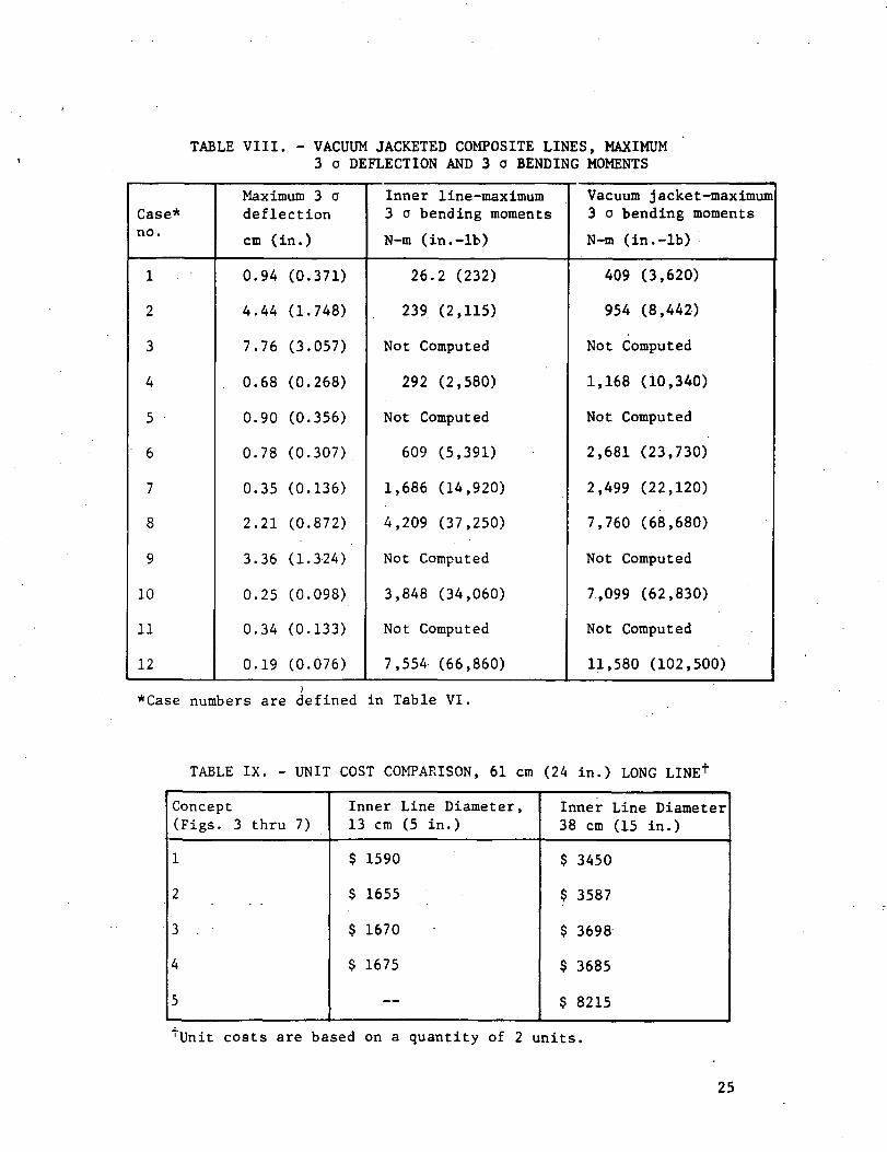
TABLE VIII. - VACUUM JACKETED COMPOSITE LINES, MAXIMUM3 a DEFLECTION AND 3 o BENDING MOMENTS
Case*no.
1 .
2
3
4
5
6
7
8
9
10
11
12
Maximum 3 odeflection
cm (in.)
0.94 (0.371)
4.44 (1.748)
7.76 (3.057)
0.68 (0.268)
0.90 (0.356)
0.78 (0.307)
0.35 (0.136)
2.21 (0.872)
3.36 (1.324)
0.25 (0.098)
0.34 (0.133)
0.19 (0.076)
Inner line-maximum3 o bending moments
N-m (in.-lb)
26.2 (232)
239 (2,115)
Not Computed
292 (2,580)
Not Computed
609 (5,391)
1,686 (14,920)
4,209 (37,250)
Not Computed
3,848 (34,060)
Not Computed
7,554 (66,860)
Vacuum jacket -maximum3 o bending moments
N-m (in.-lb)
409 (3,620)
954 (8,442)
Not Computed
1,168 (10,340)
Not Computed
2,681 (23,730)
2,499 (22,120)
7,760 (68,680)
Not Computed
7,099 (62,830)
Not Computed
11,580 (102,500)
*Case numbers are defined in Table VI.
TABLE IX. - UNIT COST COMPARISON, 61 cm (24 in.) LONG LINEf
Concept(Figs. 3 thru 7)
1
2
3 .
4
5
Inner Line Diameter,13 cm (5 in.)
$ 1590
$ 1655
$ 1670
$ 1675
—
Inner Line38 cm (15
$ 3450
$ 3587
$ 3698
$ 3685
$ 8215
Diameterin.)
^Unit costs are based on a quantity of 2 units.
25

Conclusions: From these analyses we conclude that 6.1 m(20 ft) unsupported spans, whether convoluted or nonconvoluted,are not acceptable within the limits of the 20-Hz minimum require-ment, and that intermediate supports are required.
Stress analyses indicate that the bending moments computed forboth the inner line and the vacuum jackets are at acceptable levelsfor Shuttle applications. The deflections computed have not beenevaluated in terms of acceptability since this depends on designdetails of a Shuttle configuration and the proximity of the linesto the spacecraft, but appear to be in an acceptable range.
Structural and Dynamic Analyses of Tension Membrane VacuumJacket. These analyses were performed by the Grumman AerospaceCorporation and are included in this report in Appendix E. Theresults of these analyses are summarized in the following para-graphs.
Structural analysis: The tension membrane shell consists ofa series of toroidal segments that carry load to intermediaterings in suspension bridge fashion. Unlike sandwich and discretestiffener cylinder designs, the membrane shell is loaded in ten-sion, and thus the material can operate at a stress close to itsyield point. The compact intermediate compression rings carrythe transverse component of the membrane load and are designedfrom overall and local instability considerations. Althoughmaterial is used at a high efficiency in the membrane shell, itis not able to sustain longitudinal loads unless supported atits ends. In application to vacuum jacketed lines, it is conve-nient to use the inner line to support the tension membrane shellends.
The key assumption in the formulation of the tension membraneshell theory is that the membrane is permitted to buckle hoopwisewith the pressure load being carried along the meridian direction.This expected physical behavior can be incorporated into the anal-ysis in one of two ways:
1) assume that the hoop stress resultant is equal to zero, or
2) analyze the membrane as an orthotropic shell with itscircumferential modulus of elasticity small compared toits meridional modulus.
If the annulus, between the outer shell and the pressure vesselis specified, then for a given membrane depth, a design exists foreach ring spacing, and weight, per unit length of outer shell can becomputed. As the ring spacing decreases, the r^, radius of curva-ture of the membrane decreases, and the required jacket thicknessis reduced. With the skin at minimum thickness, ring spacingswere further decreased beyond the minimum weight point to reduce
26

the axial load produced by the membrane for reasons of compatibil-ity with the inner line design. The inner line design placed a max-imum compressive limit load on the LH£ line to 175 N/cm (100 lb/in.) of circumference. This load was achieved by holding the sagof the catenary constant while decreasing the ring spacing. Froma dynamic (vibration) viewpoint, such designs of increased flexi-bility exhibit high flexural stresses. To reduce the flexibilityand flexural stresses, the final design maintains the same meri-dional radius of curvature (hence the same catenary tension) butreduces the sag by introducing flats over the rings.
Acoustic analysis: Requirements for the tension membrane testspecimen include withstanding an acoustic noise level of 160 dBapplied for 450 sec and 167 dB applied for 60 sec. The method ofanalysis used is depicted in Appendix E.
The analysis shows that the maximum dynamic stress will be12,170 N/cm2 (17,385 psi), sustained for approximately 26,000cycles. The endurance limit for 321 stainless steel is 26,200N/cm2 (38,000 psi), indicating that the planned exposure is safefrom a sonic fatigue consideration.
Lateral structural vibration of full tension membrane: Adynamic analysis of the tension membrane vacuum jacket was per-formed to determine its response to the required acceleration spec-tral density given in Figure 10. The fundamental natural fre-quencies, G levels, and displacements were determined for severalunsupported jacket lengths. The effective jacket flexural stiff-ness for the analysis was obtained using the Grumman STARS (shellsof revolution) computer program. The analysis incorporated bothisotropic and orthotropic behavior of the membrane. For ortho-tropic behavior, the modulus of elasticity in the hoop directionwas assumed to be equal to 10% of the modulus in the axial direc-tion. This analysis is presented in Appendix E. The calculationsshow that the peak stress in the 0.010 cm (0.004 in.) steel mem-brane reaches 86,100 N/cm2 (125,000 psi) at the edge of the ringfor a 3.05 m (10 ft) support spacing and is somewhat lower fora 1.52 m (5 ft) spacing. A 6.10 m (20 ft) support spacing isunacceptable since the maximum deflection exceeds the clearancebetween the jacket and the inner line. For a 3.05 m (10 ft)support spacing and assuming an orthotropic membrane, a 3.02 cm(1.19 in.) jacket deflection coupled with a 0.203 cm (0.080 in.)line deflection leaves a sufficient gap remaining from a 3.80 cm(1~.5 in.) initial gap'. *
If the strength of .the steel membrane is not greater than the86,100 N/cm2 (125,000 psi) level, a small thickness increase willbe required in the membrane in the vicinity of the rings.
27

It should be noted that the foregoing analysis takes no theo-retical advantage of the longitudinal tension already existing toincrease the stiffness of the membrane. At 6.10 m (20 ft) spans,this would be an important effect.
Longitudinal acceleration: The effect of longitudinal accel-eration is to produce a tensile loading in the outer jacket, sim-ilar to the loading produced by pressure. Combining pressure andaxial acceleration will produce an increase in the maximum ten-sile stress in the outer jacket. The effect of longitudinalacceleration, however, is small compared to the effect of pressure.The load due to external pressure is approximately 175 N/cm (100Ib/in.) and the load due to acceleration is 3.2 N/cm (1.8 lb/in.).
Weight Analysis. - Total vacuum jacketed line weights werecalculated for line diameters up to 25 cm (10 in.) with an opera-ting pressure of 42 N/cm2 (60 psi) absolute and for line diametersover 25 cm (10 in.) with an operating pressure of 69 N/cm2 (100psi) absolute. The theoretical weights for each concept are givenin Figures 11 and 12. Weights are presented for the tension mem-brane both in the overwrapped configuration and bare metal config-uration because some protective cover may be required on the ten-sion membrane to prevent damage for flight configuration. Theweight calculations show that there is very little difference inweight between the design concepts considered.
Cost Analysis. - Fabrication costs using stainless steel andaluminum vacuum jacket liners were estimated for each of theselected design concepts based on the test specimen configuration.These costs are provided in Table IX.
Vacuum Acquisition and Maintenance. - Thermal performance ofa vacuum jacketed line is a direct function of the vacuum level inthe annulus. An advantage of a pre-evacuated line is that it isready for use long before mission time since the pre-evacuation iscarried out during fabrication.. A disadvantage is that an extreme-ly low leak rate is required of all components making up the vac-uum jackets so that a preflight vacuum pump-down will not be nec-essary.
Whether or not the various concepts can be successfully pre-evacuated is directly related to the quality of the constructionand the outgassing of nonmetallic materials in the vacuum annulus.All selected design concepts are considered to be pre-evacuatedsystems. For the tension membrane, this will serve to rigidizethe specimen making handling and shipping easier.
28

Before sealing the vacuum annulus a preconditioning processshould be carried out. This process should include (1) chemicalcleaning of all components, (2) 100% x-ray inspection of allwelds to ensure leak free welds, (3) helium leak check of theinner line, (4) bake-out at a specified temperature and for aspecified time depending on the materials used, and (5) heliumleak check of the outer jacket.
The desired level of sealed vacuum may not be maintained withsome concepts, due to material applications or construction tech-niques. In this case, an internal vacuum pump can be installedin the line and can.be operated continuously. This would replaceground pumping before flight and maintenance between missions.The simplicity and ruggedness of the magnetic ion pump make itmost suitable for this application. Additionally, the pump canalso be used as a vacuum gage by reading the current that itdraws. This system is most commonly applied to systems withsevere requirements, 10 2 N/cm2 (10 ** torr) or lower.
Concept Evaluation Summary.- The evaluation of the variousdesign concepts was performed before fabrication and testing ofthe specimens. The evaluation indicated that all concepts arestructurally sound and capable of meeting anticipated SpaceShuttle requirements. A comparison of the predicted weightsshewed that there is very little difference in weight betweenthe various concepts, with the tension membrane having the lowestpotential weight. A comparison of fabrication costs predictedthat aluminum vacuum jackets would be significantly more expen-sive than steel. This conclusion is based on the assumptionthat the inner line is steel and that an aluminum to steel tran-sition joint is required. The cost analysis also indicated thatthe tension membrane is more costly than the other concepts bya factor of 2-K
Based on the concept evaluation performed during the earlyphase of the program, none of the design concepts showed clearsuperiority over the others. The tension membrane was the leastweight but also the most costly. One concept may be superiorfor specific mission requirements, depending upon parameter sen-sitivities, i.e., weight, cost, thermal performance, and loads.The design concepts were compared again after fabrication and test-ing of the test specimens were completed.
29

Vacuum JacketSee conceptdetail.
Inner Line
Concept 1
Concept 2
Concept 3
Concept 4
Figure 8. - Circumferential Stiffener Concepts
30

inCO
CM
•so
COCOvt-ia
o
m
vO
coCO0)
8
1.x
60
COo
COCOa)
§
un)
E3UOJ
60
mro
m(N
otssjnssaa^
o•*
on
|
o(M
Oi— 1
O
'ajnssaaa
31

1.0NX
CMoo
01c<uQ
O<uQ,C/3
CO
(0(-10)iH0)'JO
0.1
0.01 I I I I
10 100Frequency, Hz
Figure 10. - Random Vibration Input (Shuttle Launch)
1000
32

60
50, .
-C
£ 40.tf
I<U
3 3 0 .
aog.20 . .
10 .
30
25
S 20
15
10
Note: Design concepts are definedin Figures 3 through 7.
Concept 2
Concept I*
— Concept 1 and 3Concept 2
2 3 4Line Length, n
0 2 4 6 8 10 12 14 16 18 20Line Length, ft
Figure 11. - Vacuum Jacketed Composite Line Weight[42 N/cm2 (60 psi) Absolute OperatingPressure]
240
220
200. .
180.
160,
140'
120. .
100- -
80..
60. .
40. .
20. .
0. ,
110
100
90
80
00
* 70+J
* 60Su 50e
Z 4013u
£ 30
20
10
0
Note: Design concepts are definedin Figures 3 through 7.
-Concept 4
— Concept 1 and 3- Concept 2
Concept 4
Concept 1 and 3Concept 2Tension membraneConcept 5 overvrappedConcept 4Concept 1 and 3 .Concept 2
me concept 5)
2 3 4
Line Length Meters
4 6 8 10 12 14
Line Length, m
16 18 20
Figure 12. - Vacuum Jacketed Composite Line WeightJ69 N/cm2 (100 psi) Absolute OperatingPressure]
33

PRELIMINARY TESTING
A preliminary testing program was conducted to evaluate designand fabrication techniques planned for the program. Vacuum jacketstructural integrity, bonding composite materials to metal linersand composite outgassing was evaluated. The following paragraphsdiscuss the testing that was performed and results.
Vacuum Shell Integrity Tests. - External pressure testing wasconducted on two prototype composite vacuum jackets and the ten-sion membrane vacuum jacket. The configuration of the compositevacuum jackets tested is defined by the design details in Table X.Each of the test specimens was placed in a pressure chamber, asshown in Figure 13, the vacuum annulus of the test specimen wasevacuated, and the chamber was pressurized until the test specimencollapsed under external pressure. Failure was noted by a suddenchange in vacuum annulus pressure. The first test specimens col-lapsed at a pressure differential of 19.8 N/cm2 (28.7 psid), andthe second, of a different design, at 45.3 N/cm2 (65.7 psid).Both failed at 82% of theoretical collapse pressure. This cor-relation between theoretical and test actuals was considered ac- 'ceptable and provided confidence in both the fabrication and ana-lytical techniques used.
External pressure testing of the tension membrane vacuum jac-ket was performed by Grumman Aerospace Corporation with the tensionmembrane welded to a stainless steel dummy inner line. The vacuumannulus was evacuated to 0.03 N/cm2 (0.05 psi) absolute and cycledback to ambient pressure nine times to verify structural integrity.Strain gage measurements were made during the pressure cycling andtransformed into hoop and longitudinal stresses. Based on thematerial thickness of 0.019 cm (0.0075 in.) in the center bay (asdetermined by Vida gage after chem-milling), and assuming thatall the load is carried longitudinally, the stress was calculatedto be 5840 N/cm2 (8470 psi). The yield stress of 321 annealedstainless steel is 24,000 to 31,000 N/cm2 (35,000 to 45,000 psi)providing a factor of safety of: o '
FS . 24.000 . 4 i5840 *••"•
when the tension membrane is subjected to the external pressureloading of 10.1 N/cm2 (14.7 psi). Additional details pertainingto tension membrane testing are provided in Appendix E.
Bonding Tensile Test. - Bonding tensile tests were performedto evaluate the bonding characteristics of the composite overwrapto the metal inner line and vacuum jacket liners. The tests wereperformed on one inch square bonded test coupons by pulling thecoupons apart with a tensile testing machine. Test coupons weremade using a thin sheet of Inconel 718 bonded to S-Glass (Epon828-V40 resin) overwrap. The thin metallic liner was cleaned in
34

bJ
UUa,
HCOuH
HU
CJ
swa,
ico
H
a
oi—itou
iX
,JCO
cucTO
XIE01E
C 010 E•H -HCO OC 010) 0.H co
^TOC
•HE C
•H CUrH E0) -HV- 0a. 01
a•o cocO 4-1o en0) Ol
CO 4-1
iwTOC•H CE 01
••-i ErH -HO) Or4 d)a. c.
CO4-1en 4J •t-i CO
•rl CUfcU 4J
01
P4JTO0)
C60
CO01a
01cTO
JjE01E
co
•HCOc01Hun
en4-1iOa.D.3CO
a.oo
i— iTOC
CU4Jc
(—1
CO0)4-J3
1— IO
C0o
1-1TOC
<u4-1Xw*
0)rH
4-1CO
CQO•HCO
s
-5CDJ-JCO
toCOcuC•HTO4-1CO
rHCNn
OOi-lr^
t—jOlcoocM
1-1,;)0>JJCO
COCO01iHC•HTO4-1CO
iH<Nm
f— 4TO•Hl-i0)4-JTOE
a>c•H
C•H
ps»
8ON-y
ECJ
oo•-I0
•o
c•H
o1— 1oo
ECJ
inCNoo
^*\•c
•H
Oi-HO
•
o•***s
EoinCNo.
0
COCOOlco
•Hr*4J
01C
-H
~C
•H
vO
*mV— '
CJ
-3-rH
•»ni— i
yM^
•
C•H
O
•O
ECJ
rHoo
•m
^«\,c
•H
inCN•i-HN»X
Eo
oorH
•
m
60c
•HOTOO.CO
4J
Oa.3CO
^Jo(U4J3
rHO
cou
^3^^^
z
^J• x.
z
x~s•
c•H
oooo
EU
OCNoo
to.3•rtTJTO
C*
0)4-J3
i— fO
£
3
^j• s ,
82
"TO•oI"i
ooCN00
Coa.
^*s
COCOTO
rHO
1CO
/-sC•HCO01VJ
asoo\O
1oom\~s
COCOTO
i-HO1
W
rHTO•Ht-l0>4-tTOE
01
•HCOO
Eou
c•H
00
a\
s^e
CM*
Om
.— •c
•H
ihCM•
orHSw/
ECJ
voCN
/- N
•
B•H
CNrHN-X
Eo
i_4n
^40)4JcuTOiHQ
^^
•
C-H
mCN
6CJ
inmvO
y-
•
ciH
mrHs«x
ECJ
oom
x^s,
c•H
m•CNrHs«x
EU
oo•
f-l
ro
r*
60C01
^z
exoo.cyl—v
om+1
*o ^^TOt-l CO
( 01oo >,O TO
• rHO-H CN
l-i<u^tTO
ao0x
^
c^1cu4J4-1TOO.
a.n^4e01
o
•H.(0O.
«NCN
iHCM ffl
§ *fH4-1
•^ cZ 01
MCM 01' MHm IM
rH ^HA TJ
x^•HCOaO rH00 TO*~- -H
j-jCM C
E Ola i-i
-*. 01Z m
14-4m -Hm "O
x^v•HCO.aU-l rHm TO>••' »H
4JCM CE 0)U l-i
— . 0)Z *^
U-lVf -HCN T3
01£4
3COCO01fa
a01na.TO
i-H•-)ou•o014JTOrH3CJ
rHTOU
CN m4-) 4-1a a.cu cu0 CJB Co ou uo ou 4J mrl I-l 4-1TO TO CU
rH rH CD•H -H CJE E CiH iH OC/> C/> CJ
* -1- un
35

accordance with the procedure defined in the fabrication sectionof this report, and was bonded to the overwrap on one side and to1.59 cm (0.625 in.) thick steel blocks on the other side using Hysol934 adhesive. A photograph of-a typical test coupon before andafter testing is shown in Figure 14. Results of the testing arediscussed in the following paragraphs.
Inconel 718 and S-Glass test coupons (58-68R resin system):The tensile coupons tested at ambient temperature had an averagebond strength of 465 N/cm2 (765 lb/in.2). The highest value was672 N/cm2 (975 lb/in.2) and the lowest value was 338 N/cm2 (490lb/in.2). The loads were measured using a tensile machine withthe load being applied at a rate of 2224 N/min (500 Ib/min) ..
The tensile coupons tested at 97.2 (-285°F) had an averagebond strength of 1324 N/cm2 (1920 lb/in.2). The highest value was1482 N/cm2 (2150 lb/in.2) and the lowest value was 827 N/cm2 (1200lb/in.2). These loads were measured using an Instron Model TTCUniversal Tensile Test Machine with the load being applied at arate of 0.05 cm (0.02 in.) per minute.
304 stainless steel and S-Glass test coupons (Epon 828 mpdaresin system): The tensile tests were conducted at ambient tem-perature using a tensile machine with the loads being applied at2224 N (500 Ib) per minute. The coupons had an average bondstrength of 374 N/cm2 (543 lb/in.2). The highest value was 493N/cm2 (715 lb/in.2) and the lowest value was 183 N/cm2 (266lb/in.2).
•
Failure mode: All of the test coupons failed at the Hysoladhesive interface and not at the bonded composite interface withthe metal. Therefore, the actual bond strength of the compositeto the metal liner was not determined but was shown to be greaterthan the values given above.
At this point in the program, it was believed that the criteriafor a successful bond with adequate margin was 25.3 N/cm2 (36.7lb/in.2), which provides a 2.5 safety factor for tension loading,as applied by external pressure. Of all the coupons tested, thelowest bond strength was 183 N/cm2 (266 lb/in.2), or a factor of7.2 times the required strength. Thus, the need for more exten-sive testing and a more accurate determination of Bond strengthwas not recognized. It was found later that bond strength in peelis also critical to the vacuum jacketed design, This ±s discussedin the Design and Fabrication sections.
Composite Outgassing Tests. - Testing was performed to determinethe outgassing characteristics of S-Glass and 58-68R resin systemsin a typical vacuum jacket annulus. Test samples were made from1.90 cm (0.75 in.) diameter composite tubes that were overwrappedand cured to the same procedure as planned for the inner line of
36

the vacuum jacketed composite lines. Immediate indications fromthe testing were that composite post curing would be required toreduce outgassing rates to acceptable levels. Samples of S-Glassand 58-68R resin composites were prepared and postcured as follows:
Specimen 1 - Postcured at a temperature of 413 K (285°F) anda vacuum of 10~3 N/cm2 (10~5 torr) for 48 hours."
Specimen 2 - Postcured at a temperature of 413 K (285°F) anda vacuum of 10~3 N/cm2 (10~5 torr) for 72 hours.
Vacuum thermal weight loss tests that involved continuouslymeasuring the specimen weight in a vacuum were performed at ambi-ent temperature for 72 hours. The results of these tests are plot-ted in Figures 15 and 16. Specimen 1 (48-hr postcure) experiencedweight reduction for 54 hours and then stabilized, i.e., no furtherweight reduction was detected. Specimen 2 experienced weight lossfor 12 hours with the major loss occurring in the first 2 hours ofthe test. The steep portion of this curve shows the specimen giv-ing off moisture that had been absorbed after the postcure and be-fore the start of the test. The dramatic difference in the twocurves is an indication that the optimum postcure time is somewherebetween 48 and 72 hours.
It was concluded from these tests that a 72-hour vacuum post-cure would be required for the composite on the inner lines toassure capability to maintain a vacuum in the vacuum jacketedlines.
37
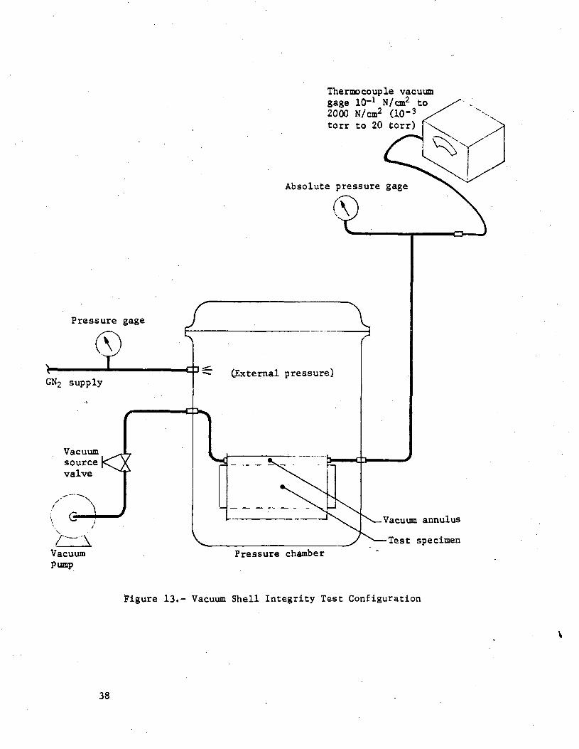
Pressure gage
GN2 supply
Vacuumsourcevalve
AVacuumPump
Thermocouple vacuumgage 10-1 N/on2 to2000 N/cm2 (10-3
torr to 20 torr) f
Absolute pressure gage
(External pressure)
Pressure chamber
-Vacuum annulus
-Test specimen
Figure 13.- Vacuum Shell Integrity Test Configuration
38
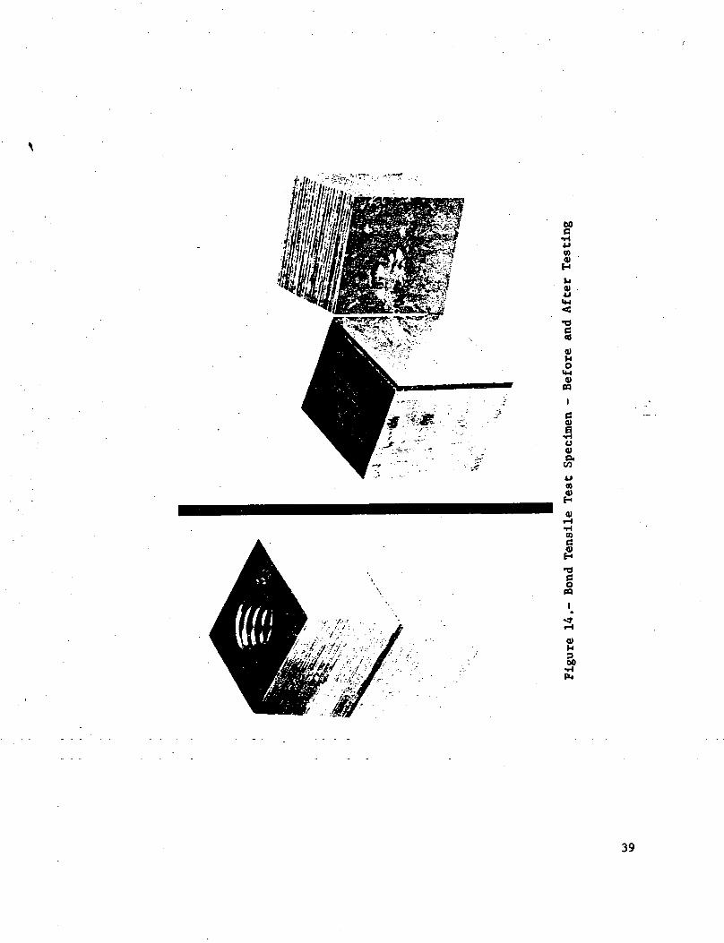
60
i-l4J0)
0>
•o§0)1-1o
U-l0)m
Iu0)
4Jtn&
m§H
•O
§PQ
39

+0.1
Initial weight = 1,196.050 mg
Specimen 1;
-0.6
1)2)
3)
Sample: S-Glass in S8-68R Resin.Sample Postcure: 72 hr at 413 K(285°F) in a vacuum less than1.3xlO-3 N/m2 (10~5 torr).Test was run at 294 K (70°F) in avacuum of l.SxlO-1* N/m2 (10~6 torr) .
Final weight =1,195.690 mg
12 24 36Time, hr
, 48I I I
60 72
Figure 15.- Outgassing Test Results after Test Sample 1Had Been Vacuum Fostcured for 48 Hours
Specimen 2;1) Sample: S-Glass in 58-68R Resin2) Sample Postcure: 48 hr at 413 K (285°F) in
a vacuum less than 1.3xlO~3 N/m2 (10-5 torr).3) Test was run at 294 K C70°F) in a vacuum of
1.3x10-* N/m2 (10-6 torr).
Initial weight - 2,549,6710 mg
-0.04
Final Weight •2,549.6489 mg
I I I I 1 I I I12 24 36
Time, hr60 72
Figure 16.- Outgassing Test Results after Test Sample 2Had Been Vacuum Postcured for 72 Hours
40

TEST ITEM DESIGN
Using the results of preliminary tests and the design informa-tion developed during concept design evaluation, six each 13cm (5 in.) and six each 38 cm (15 in.) ID vacuum jacketed compositelines were designed depicting each of the selected concept config-urations. The designs consisted of 63.5 cm (25 in.) long line sec-tions with end fittings, vacuum instrumentation, and all necessaryhardware. Additional design included thermal and strain instru-mentation for use in the test program, and special overwrap andleak test tooling.
The vacuum jacketed composite line configurations, which wereselected at the completion of these analyses, are representative ofthe liquid hydrogen feedlines required for Space Shuttle and SpaceTug.
Physical Dimensions and Properties. - Physical dimensions andproperties of the inner lines and the vacuum jackets for each of theselected design concepts are shown in Table XI.
Detailed engineering drawings were prepared for each designconcept and copies of the drawings were included in the SecondQuarterly Progress Narrative (ref. 3). The materials of construc-tion and fabrication techniques are summarized in the fabricationsection of this report.
Design Objective. - The design objective was to develop workabledesigns for each of the selected design concepts by applying tech-nology from earlier composite feedline studies to vacuum jacketedcomposite feedlines. The design criteria, which were major con-siderations in the test item design, were defined in Table I.
End Fitting Design. - The criteria for end fitting design in-cluded:
1) capabilities of the various liner fabricators to weld thinfoil to a relatively thick section of flange; t
2) ease of assembly of the vacuum jackets over the innerlines;
3) thermal mass, stress concentration, and vacuum carry-through capability of vacuum jacket end fittings;
4) closure of the vacuum annulus;
5) ease of connecting composite tubes to other compositesections and to metallic end caps;
6) butt weld type fittings were selected for joining twosections of vacuum jacketed line to minimize weight and leakage.
41

CO
PR
OP
ER
TIE
a
' SN
OIS
N
rh-»a
PH
YS
ICA
L
BM
EdH
1
h-tX!"
Ed
I
He
at
tre
at
00c
•HUU
IM
•acu
COCD
3fHO
C
CJ
T3i-H0)3
i— I03
•o3u
occ2
COCOat
c.
.£
ft
Ma
teri
^0c0
Dia
me
ter,
e01
•H
CO
c0)•0hiCO
0)00CO
cCO
*
101
>,en
01a.
AJo-
c•H
E
C
SCJ
c
eCJ
cCO
c
| configura
tic
CO
01
eoCO3b.
CO
f-4CO
rH
enoO
O
CO
O
0
o
CN
m
en<o
en
en
0)
01ee
co
- coCO3Ci.
c5«
r-1
mooo
en
oo
sinCN
inentO
IA
cn
en
0)
SJu0)e
•e
CO0)
.ance
Re
sis
t1st ance
s
rH
inooo
enoo
oinCN
inen•a
in
oocn
vO
0)e
«H
U01cc
oz
coCO
u.
CM
COc01
XId
eo
•HCO
CM
•aooo
ino0
inCM
enCN
O
0m
£
oCM
CM
Va
cuu
m Jackel
Co
nce
pt
1
oz
coCO3
EL,
CM
CO
C
01
X
Id
coCO3
en
I
O .
moo
inCM .
enCM
O
ONin
CO
CN
Va
cuu
m J
ackel
Concept
3
o
§CO3b
3
<0C
0)
&us io
n
CN
§C3
O
d
inCN
CM
o
00
s
CM
Vacu
um
Jackel
Concept
2
• « •
C0
CO3
Ex
CM
COC
01
XId
us io
n
en
o
moo
CM
enCM
o •ejim
00iH
CN
Vacu
um
Ja
cke
tC
oncept
2
oz
§CO3
Eb
m
COe0)
c
coCO
CM
•aooo
mo0
inCM
enCM
o
m
00
S
CM
Vac
uum
Jackel
Concept
A
oz
z"
m
01c cO CO
co .n
0) 0)£- S
Co-Hcn3
-
^
OO
o
0
0
mCM
enCN
0
m
00
vO
CN
Vacu
um
Ja
cke
tC
on
ce
pt
5
CO
0)
CJ
4-1
CO
V00CO
IV
09
01X
4J
•o01r-l
•H
e
CJ
(-1 •
JJ
COCO0)
(0 0)
0} CO
iH CO
cn CD03 5• JJ
JJ COCO O
co en
U •"• CMC E O
rials
are
Inco
mem
bra
ne
vacu
u
ngs
we
re
mad
e
01 •Hu c «a 5 i
CO *M
3 § -a« - g•O 0)0) J= -O4J JJ 01
Exce
pt
as
nc
*Mate
rial
of
Wh
ere
re
quii
on
ce
pts
u
Vacu
um
Jacke
eou

The thickness of the main body of the end fitting is control-led by three factors: (1) minimum thickness to withstand internalpressure (inner line) and external pressure (vacuum jacket); maxi-mum thickness permitted by the welding process that is generallythree times the liner thickness; and (3) the required thickness tojoin the tube to an adjacent component. Diagrams of the end fit-tings designed for the various test items are shown in Figure 17.
The end fitting selected for the 38 cm (15 in.) diameter innerlines was designed for a resistance welded liner-to-end-fitting-joint. The end fitting selected for the 13 cm (5 in.) diameter in-ner lines is similar to the large fitting except for the weld preparea which is shaped to provide an approximately equal area foreffective weld heat buildup during welding. This style of endfitting is designed for a fusion weld liner-to-end-fitting-joint.The end fittings selected for the 46 and 20 cm (18 and 8 in.) vacu-um jackets, were designed to be fusion-welded to the thin vacuumjacket liner and heliarc-TIG welded to the thick portion of theinner line end fittings. Figure 18 shows typical installation ofthe vacuum jacket end fitting over the inner line end fitting.Figure 19 shows typical installation of the tension membrane endfitting over the inner line end fitting.
Inner Line Design. - The inner line design analyses (linerheat treat versus annealed, bonding, torsion loading, and tensionloading are included in Appendix A. The final conclusion after
Prconsidering analyses results, and the S = — relationship, was that
liner material thickness is determined by minimum gage manufactu-ing and handling limitations. A design objective was to not exceedthe yield stress of the liner material at the line working pres-sure. This was easily achieved by 0.008 and 0.013 cm (0.003 and0.005 in.) heat treated Inconel 718 with a yield strength of114,000 N/cm2 (165,000 psi). The hoop stresses, at working pres-sure are 34,500 N/cra2 (50,000 psi) and 103,000 N/cm2 (150,000 psi)for the 13 cm (5 in.) and 38 cm (15 in.) diameter lines, respec-tively.
This design approach results in the overwrap providing addi-tional design margin and handling capability. It is significantthat the overwrap is not required for pressure loading.
Vacuum Jacket Design. - The structural design analyses of thevacuum jackets for radial and axial external pressure loading,performed during concept evaluation, determined the liner and over-wrap thickness, convolute size and spacing, standoff support con-figuration and spacing, and the tension membrane configurations.
43

Test Item Assembly Design. - To facilitate testing and totest a typical joint configuration, the vacuum jacketed compositeline test configuration consisted of two like design conceptsbutt-welded together as shown in Figure 20. Heavy weight tubecaps were used for interfacing with the test facility. Thermo-couples and strain gages were designed .for installation as shownby Figure 20, and are indicated by Tl, T2 . . . and SI, S2, . . .,respectively. The instrumentation wiring was fed through thevacuum end closure via vacuum connectors. The vacuum annulus ofeach tube was manifolded together with 1.27 cm (0.50 in.) diametertubing to a VEECO vacuum isolation valve. A cold cathode ioniza-tion gage was provided in the manifold for monitoring vacuum inthe range of lO"1 to I0~k N/cm2 (10~3 to lO"6 torr).
Tooling. - Concurrent with the test item design a mechanicalfixture to serve as a leak check tool, proof pressure tool, andoverwrap tool was also designed. Figure 21 shows the basic de-sign concept of the tool. Separate fixtures were designed foreach different diameter tube and vacuum jacket. A heavy weightinner line was used for structural integrity and leak checks onthe tension membrane jacket.
Vacuum Jacket Design Modification. - Upon initial pump-downof the vacuum jacket annulus, a collapse of the vacuum jacket wasexperienced due to external pressure. Failure analysis (Appendix -D) revealed that the bond of the glass-fiber overwrap to the metalliner had failed, thus exposing the liner to total external pres-sure loading. Investigation and testing performed during the fail-ure analysis showed that the bond line was loaded in peel insteadof pure tension. The bonding strength in peel was poor, even onspecially prepared test samples. It was further found that whenthe composite structure was loaded, but in a manner so as not toload the bond line, the structure developed anticipated strength.
As a result of this failure and subsequent analysis, it wasconcluded that the concept of using a very thin metallic linerbonded to a glass-fiber overwrap was not workable with the sur-face preparation and bonding techniques used. While others havehad success in making bonds with good peel strength using dif-ferent resin systems and surface roughing techniques, it was ap-parent that bonding development beyond the scope of this contractwould be required to obtain an acceptable process. This conclusionled to the development of an evacuated bag, which was placed overthe composite vacuum jackets during testing, and to the redesignof the vacuum jacket liners.
A typical evacuated bag installation on the composite vacuumjackets is shown by Figure 22. The effect of the evacuated bagwas to transfer the external pressure loading to the outside ofthe composite structure and thus eliminate the loading on thebond. This configuration proved successful and was used on theremaining composite vacuum jackets throughout the test program.
44

The vacuum jacket redesign consisted of increasing the linerwall thickness, as required, to withstand external pressure load-ing without a requirement to bond the liner to the overwrap. Theoverwrap is still applied to provide liner protection in handlingand additional structural margin. Calculated metal liner thick-nesses required for the composite vacuum jacket design are pro-vided in Table XII.
TABLE XII. REQUIRED VACUUM JACKET LINER THICKNESS TO WITHSTAND25 N/cm2 (36.7 psi) EXTERNAL PRESSURE VERSUS LINER DIAMETER
Vacuum jacketdiameter (OD)
cm (in.)
13 (5)
20 (8)
33 (13)
46 (18)
58 (23)
Liner gage
cm (in.)
0.025 (0.010)
0.030 (0.012)
0.035 (0.014)
0.041 (0.016)
0.046 (0.018)
Without overwrap, the metal liner thickness required for externalpressure does not provide adequate resistance to damage for handlingduring installation or maintenance. Since the overwrap is of verylow density, the overwrapped line is of lighter weight than theconventional all-metal, vacuum jacketed line which would requirea thicker metal gage.
45

-LiDM
(15 in.) aicaatar Um*r Jtaa «od ftteln* d«*l
Fiutee veld -
Mec«i 1. tnuloa Mabr«a* 414 act lacorporat* th* u»» ot m ai (itetaj,2. cvuloa «abr«n« «ld«d dlr.ctly to th« tan«r llo« (Fl«. 19}.
Figure 17. Inner Line and Vacuum Jacket End Fitting Configuration
tm ca (9 ia.j aiMmmcmr '
13 ca <3 la.) di«MC*r laa«r j/"lla.r II jr
^-H«ll»rc-TIG weld
(eyp)
-Fu«loa veld (cyp)
iactftlUtloa 20 en (8 la.) dimetr vteuua Jtelutovtr 13 ca (3 la.) dUa«t*r laacr lla« ut
_. 46 ca (18 la.) dloaear vccuua Jacket lia«r,/ coavoluttd u r^uirtd
Typical lavcalUcloo 44 ca (18 la.) dltaatar vacwa Jaekatovar 38 ca (1) ia.) dl«a*t«r laaar Horn
Figure 18. - Vacuum Jacket Installation Over Inner Line
Figure 19. - Tension Membrane Installation Over Inner Line
46


0)c
0)
uat -
o
4)coOT
00COpq
o
2I
cses
<U
00•Hfc.
48

FABRICATION
The fabrication effort consisted of the following major func-tions :
1) evaluating and selecting vendors;
2) fabricating liners;
3) fabricating end fittings;
4) joining liners and end fittings;
5) overwrapping and curing the assembly (except tension mem-brane vacuum jacket);
6) mounting instrumentation;
7) joining inner liners and vacuum jackets; and
8) performing various in-process leak checks.
The materials, manufacturing and welding techniques, alongwith fitting fabrication and fitting attachment processes used toproduce the test item inner liner, were similar to those developedon earlier programs. New techniques, however, were required tofabricate vacuum jacket liners and to overwrap internal and ex-ternal convolutes. The quantities fabricated were:
six-13 cm (5 in.) diameter inner lines
six-38 cm (15 in.) diameter inner lines
six-20 cm (8 in.) diameter vacuum jackets
six-46 cm (18 in.) diameter vacuum jackets (includes 2 tensionmembrane vacuum jackets).
The general fabrication sequence for the test items is de-«-picted by the flow charts shown in Figures 23 through 26.
End Fitting Fabrication.- The requirements of the program dic-tated that butt-weld style, flight-weight fittings be used on thetest specimens. The weld prep configurations of the end fittings,where the liner is joined to the end fitting, were developed by theliner fabricators.
To facilitate assembly of the vacuum jacket over the innerline, the end fittings of the vacuum jacket were dimensionallycontrolled to provide a minimum clearance fit over the inner lineend fittings. One end fitting was machined to a smaller outside
49
diameter than the other to facilitate assembly. All compositeline end fittings were made of 304 stainless steel. The 13 cm(5 in.) inner line end fittings were machined from sections ofpipe. The 38 cm (15 in.) inner line end fittings were machinedfrom rings that were rolled from flat stock and seam welded. Thevacuum jacket end fittings were machined from a solid plate.
Liner Fabrication and Joining End Fittings.- The three differ-ent methods of liner fabrication that were used include resistancewelded, fusion welded from stock of desired final thickness, and,for the tension membrane, fusion welded from thick stock and chem-milled to desired final thickness. The type of weld used to formthe liner was also used to attach the end fitting (either resistanceor fusion welding).
Resistance welding technique: Resistance welding the innerliner (Fig. 27) required the liner to be roll-formed to the de-sired diameter with a slight overlap and mating surface. An anodewas placed in the liner and a resistance weld run down the lengthof tube. The excess overlap on both the inside and outside of thetube was then peeled away from the weld. After peeling the end fit-tings were installed on the liner using the same welding technique.A major advantage of this weld method is that heat treating and agehardening can be performed before resistance welding, and the lowheat and small heat-affected-zone do not degrade the heat treat.
The 38 cm (15 in.) inner lines were all fabricated by resis-tance welding, one of which is shown in Figure 28.
Fusion welding technique: The liner was formed by rolling atube of the final thickness material (Inconel 718) to the properdiameter and preparing each of the butting edges with a slightcurl. The seam along the length of the liner was then fusionwelded polished and planished, thus making the weld area conformto overall tube size with no weld buildup inside or outside thetube. Next, inner line liners were heat treated and age hardened,followed by fusion welding of the end fittings. The vacuum jac-kets were fusion welded but not heat treated; convolutes wereformed and end fittings were fusion welded to each end.
This fusion welding process was used for the 13 cm (5 in.)diameter inner lines and all of the vacuum jackets except the ten-sion membrane. Figures 29 through 33 show a typical assembly ofeach design concept.
Fusion welding from thick stock and chem-milling to the desiredfinal thickness: The liner was formed by rolling a tube from0.046 cm (0.018 in.) thick stock (321 stainless steel) to 38.4(15.1) diameter and preparing each of the butting edges with aslight curl. The seam along the length of the liner was thenfusion welded, polished and planished, thus making the weld area
50

conform to overall tube size with no weld buildup inside or out-side the tube. The liner was then pressure formed into the ten-sion membrane configuration and chem-milled to the desired thick-ness [0.018 cm (0.007 in.) through 0.025 (0.010 in.) thick sec-tions]. This technique of liner fabrication was used only on thetension membrane concept. Figure 34 shows the completed tensionmembrane vacuum jacket.
Convolute formation: Before installing end fittings on thecomposite vacuum jacket liners, convolutes were roll formed into ;the vacuum jackets. Two types of convolutes were used; internaland external. The convolutes served to increase the structuralcapability of the vacuum jacket and/or provide an expansion/con-traction capability.
The external convolutes were formed one convolute at a time.An internal, six piece, mechanical, expanding, pie die was used inconjunction with finishing rollers to form the convolute (Fig. 35).Starting with an annealed liner, a properly sized pie die was in-stalled inside the liner and expanded to one-quarter the desired .-,..convolute height. The pie die was then contracted and rotated 0.5 >rad (30 deg). It was again expanded, this time to one-half thedesired convolute height. This procedure was repeated at three-quarters the desired convolute height and at the final desired con-volute height. Rotating the pie die served to reduce the flatareas developed at the split portions of the die. However, sincethe rotating procedure did not completely eliminate the flat spots,it was necessary to use finishing rollers to finish the convolute.A roller machined to the convolute shape was set inside the liner ?in the convolute. Two rollers straddled the convolute on the out- .;,side of the liner. Simultaneously, all rollers then traveledaround the convolute smoothing the flat areas. The convolute wasthen complete. The process was repeated for each convolute. Theliners did not require any additional annealing during the variousformation heights of the convolutes.
The internal convolutes were formed, one convolute at a time.An internal mandrel with the proper number and shape of convoluteswas used with an external roller to form the convolutes (Fig. 36)..Starting with an annealed liner, .the mandrel was installed insidethe liner. A regulated constant force was applied to the externalroller forming the convolute to one-quarter its desired depth. Theliner was allowed to float on the internal mandrel and the rollerwas rotated forming -the convolute. After one revolution, the forceon the roller was increased, another revolution was made and theconvolute was at one-half the desired depth. A total of 4 revolu-.tions are required to reach the desired convolute depth. The proc-ess was repeated for the desired number of convolutes. The convolutesachieved by this process are smooth and do not require additionalfinishing. The liners do not require additional annealing during thevarious formation depths of the convolutes. Internal convolutes wereused on two of the 20 cm (8 in.) diameter vacuum jackets.
51

The tension membrane shown in Figure 37 is formed using anentirely different process. After fusion welding, the liner isannealed and is installed in a hydrostatic bulging die. Theliner is prebulged, annealed, and then final-formed. After form-ing, the liners are chem-milled to the final jacket thickness.
The tension membrane requires support rings (Fig. 38) forstructural integrity. After installing support rings, straingages, vacuum valve, vacuum sensor, and instrumentation feed-throughs, the tension membrane was welded to a composite innerline resulting in the completed assembly shown in Figure 39.
Two tension membrane assemblies were fabricated. Additionalfabrication details are provided in Appendix E.
Overwrap Application. - After inner line and vacuum jacketliner assemblies were complete, they were prepared for overwrap.All liners were overwrapped" except the tension membrane vacuumjackets. Just before overwrap, the liners were cleaned to pre-pare the liner surfaces for bonding the glass/resin matrix to theliners. The cleaning procedure used was as follows:
1) the liner was degreased with methyl-ethyl-ketone andtoluene;
2) the liner was thoroughly washed with an alkaline detergentat 311 to 344 K (100 to 160°F) consisting of the following:
parts/weight
Sodium metasilicate 3.0
Tetrasodium pyrophosphate 1.5
Sodium hydroxide 1.5
Nacconal NR (Allied Chemical Company) 0.5
Distilled water 134.0
3) rinsed thoroughly with cold, running tap water, followedby distilled water;
4) air dried at ambient temperature as observed by visualinspection;
5) brushed over area to be bonded with Pasa-Jell 105, letset for 30 minutes, and rinsed thoroughly with tap water;
6) applied the overwrap within two hours after rinsing offthe Pasa-Jell 105.
52

The overwrap on the inner lines consisted of three distinctlayers: hoop, longitudinal strips of cloth, and hoop, appliedin that order. The hoop roving was applied under 1.4 kg (3 Ib)wrap tension. The longitudinal cloth was laid the length of theliner, and consisted of equal widths of cloth separated by equalwidth gaps. The hoop wound glass-fiber roving was 20 end S/HTS-901 fibers preimpregnated with 58-68R resin. The longitudinallylaid cloth was 1557 glass, hand-impregnated with 58-68R resin.The resin content was 20 to 25%. The hopj> wound roving was ap-plied at a rate of 6.3 turns/cm (16 turns/in.). Required instru-mentation was installed on the longitudinal cloth and secured inplace when the final hoop layer of overwrap was applied. TableXIII shows specific details of the overwrap of the inner lines.The 58-68R resin matrix and cloth mat require a cure cycle atelevated temperatures. The composite cure cycle used on theinner lines is depicted in Figure 40. Constant positive internalpressure was maintained during overwrap and cure. In addition tothe overwrap already defined, four of the 38 cm (15 in.) innerlines required additional overwrap. A center support pad con-sisting of 12 layers of cloth 2.0 cm (0.8 in.) wide was appliedaround the circumference of the tube. The resin matrix and curecycle were identical to that used on the inner line with positivepressure maintained in the line during cure.
TABLE XIII.- INNER LINE TEST ITEM OVERWRAP PARAMETERS
Test item
13 cm(5 in.)DiameterInner Line
38 cm(15 in.)DiameterInner Line
Quantity
6
6
LinerInternalPressure
N/cm2 (psi)
13.8 (20)
10.3 (15)
Overwraptension per20 ends
kg (Ib)
1.4 (3.0)
1.4 (3.0)
Longitudinalcloth widthand gap
cm (in.)
2.2 (0.87)
2.2 (0.87)
53

The overwrap on the vacuum jackets consisted of two layers ap-plied at a (+) and (-) 0.09 rad (5 deg) angle, criss-cross pat-tern. The glass-fiber roving was 20 end S/HTS-901 fibers preim-pregnated with Epon 828-mpda resin.. The resin content was 32 to38%
Required instrumentation was installed under the last layer ofoverwrap. Table XIV shows specific details of the overwrap of thevacuum jackets. The Epon 828-mpda resin matrix requires a curecycle at elevated temperatures. Several combinations of time andtemperature are acceptable. Figure 41 shows the cure temperatureprofile used for the vacuum jackets. Positive internal pressurewas maintained during overwrap and cure. In addition to the over-wrap already defined, two of the 20 cm (8 in.) vacuum jackets re-quired additional overwrap. Concept 1 required additional hooprings around the circumference of the tube. The layers of hooproving were applied over a 0.3 cm (0.125 in.) width 14 equalspaces along the vacuum jacket. The wrap tension, roving, resinmatrix, and cure cycle were identical to that used on the jacket.
Positive pressure was again maintained during overwrap and cure.Figure 42 shows an overwrapped inner liner with a center supportpad.
Hoop support rings: The hoop support rings used in Concept 3were fabricated by wrapping 12 layers of hoop roving to a widthof 0.19 cm (0.075 in.) on a mandrel 46 cm (18 in.) in diameter,and curing the resin matrix. The hoop rings were then cut fromthe mandrel and splice taken out. When installed in side thevacuum jackets (Fig. 46), the rings exert a small radial force onthe liner. With the ends butted together, the ring will take com-pressive loads. Forty-four of the support rings were required.
TABLE XIV.- VACUUM JACKET TEST ITEM OVERWRAP PARAMETERS
TestItem
20 cm(8 in.)diametervacuum j acket
46 cm(18 in.)diametervacuum jacket
Quantity
6
4
Liner internalpressure
N/cm2 (psi)
12.4 (18)
6,2 (9)
Overwrap tensionper 20 ends
kg (Ib)
1.4 (3)
1.4 (3)
Wrap angle (+)(-) per 2 layers
rad (deg)
0.09 (5)
0.09 (5)
54

The wrap tension, roving, resin matrix, and cure cycle wereidentical to that used on the inner lines.
Composite structural supports: All of the 46 cm (18 in.)vacuum jackets required internal standoff supports.
The standoffs were fabricated by laying cloth and roving overa matched metal tool, formed to a 2.1 rad (120 deg) segment of acircular I-beam (Fig. 47). The cloth used in the layup was 181,while 20 end S/HTS-901 was used as the roving. The 58-68R resinmatrix was used with an elevated temperature cure. The matchedtool was clamped to provide restraint to the composite during thecure cycle. Twelve composite I-beams were constructed for use inthe four 46 cm (18 in.) vacuum jackets. Three of the I-beamswere installed in each jacket forming one continuous I-beam aroundthe circumference. The I-beam was joined with aluminum splicetabs and if 10 screws. When the vacuum jacket assembly is installedproperly over the inner line, the I-beam will rest over the innerpad forming a structural tie between the vacuum jacket and theinner line, normally called the standoff. In a total vacuum con-dition, i.e., in space, there will be a thermally efficient gapbetween the standoff and the inner line.
In-Process Leak Checks.- Two types of in-process leak checkswere performed on the test items. These were helium mass spec-trometer and dye penetrant leak checks. Dye penetrant leak checkswere made on the liner and end fitting welds. Low pressure hel-ium mass spectrometer leak checks were performed on the completedliner assemblies by the liner fabricators. Safety restrictionsand/or material yield strength precluded leak checks at operating .pressure until the overwrap system was installed and cured. Uponreceipt of the test items from the vendors, another low pressurehelium leak check was performed to determine if any damage occur-red during shipping. The final in-process leak check at operatingpressure was performed after the assembly had been overwrapped andcured. The results of the leak checks are covered in the Testingsection.
Insulation Installation.- To improve the emissivity charac-teristics of the composite inner lines, one layer of double alum-inized '4-mil mylar was installed over the composite. Figure 48shows a typical installation of the aluminized mylar.
55

Required Modification and Fabrication Problems.- During fabri-cation of the various test items, the following problems which re-quired some modification of the design criteria were encountered:
Inner line liners [13 cm (5 in.)]: The system operating pres-sure of 41 N/cm2 (60 psi) absolute, dictated that the lines couldbe fabricated at the previously established minimum gage for com-posite lines, which was 0.008 cm (0.003 in.). Upon receipt of the13 cm (5 in.) diameter inner lines from the fabricators, the heliummass spectrometer leak check revealed unacceptable leakage rates inall six of the inner line assemblies. The inner lines were returnedto the fabricator where an attempt was made to salvage the lines byrepairing the leaking welds. Three of the lines were salvaged. Be-fore proceeding with refabrication of the other three, the vendorrequired an increase in the tube thickness from 0.008 to 0.013 cm(0.003 to 0.005 in.) for the following reasons:
1) Welded part rejection rate was approximately 10 tr> 1 forthe 0.008 cm (0.003 in.) thickness.
2) Leakage through the grain structure in the 0.008 cm (0.003in.) thickness is not uncommon; therefore, in some instances, leak-age cannot be prevented, driving part rejection rates even higher.
3) With the high rejection rate and relatively high cost, ofthe welding process and materials, this thickness would probablybe cost-prohibitive for any production contract.
Vacuum jacket liner welding: The original design of the vacuumjacket liners called for fabrication using 304 stainless steel.Complications developed in attempting to weld the material. Thevendor's particular mill run of 304 stainless steel stock provedto be porous and not of the highest purity required to achievegood welds for this thickness of material. The alternative sug-gested by the fabricator was to switch to Inconel 718.. Thechange was approved.
Assembly welding: During the welding of an externally convo-luted 20 cm (8 in.) vacuum jacket to a 13 cm (5 in.) inner linea hole was burned through the glass overwrap and the liner of thevacuum jacket. This was caused by an improper grounding techniqueduring the welding operation. A standard grounding procedure wasdeveloped as a result of this incident, and was used successfullyfor the remaining welding.
With the use of a cryogenic, vacuum compatible adhesive, anattempt was made to repair the burned hole in the liner. A sub-sequent failure (implosion) of the liner during initial vacuumpull-down, did not allow an evaluation of the success of the re-pair. It was noted, however, after the vacuum jacket imploded,that the adhesive still filled the burned hole. A complete dis-cussion of this failure is provided in Appendix D.
56

Test Item Assembly.- After overwrap, installation of the com-posite I-beams, support rings and insulation, the inner lines andvacuum jackets were prepared to be joined into assemblies. Holeswere drilled in the vacuum jacket end fittings to install instru-mentation feedthroughs and vacuum access ports. A 1.27 cm (0.5in.) stainless steel tube was used for the vacuum port and a 0.95cm (0.375 in.) stainless steel tube was selected for the instrumen-tation feedthrough. After welding these in place, the vacuum jac-kets were mated with the inner lines and welded. End caps to in-terface with the test facility were welded into each end of thetest specimen as shown in Figure 49. The vacuum annulus of eachtube was manifolded together with 1.27 cm (0.5 in.) tubing thatcontained a vacuum isolation valve, a connector for vacuum read-out, and a burst disk. The assembly was completed by adding foaminsulation over the weld joining the two lines, and over the tubecaps at each end.
Test Fixture Design and Fabrication.- Test fixtures were eithermodified from those used in Contracts NAS3-12047 and NAS3-14370(ref 1 and 2) or specifically designed for this program. A testfixture was designed and fabricated for use on the thermal, pres--sure cycle tests, pressure surge tests, and acoustics tests. Thethermal, pressure cycle test fixture consisted of a liquid hydrogensupply, liquid nitrogen supply, hot gas supply, and structuralsupport. The pressure surge test fixture consisted of a liquidnitrogen supply and structural support. The acoustic test fixtureconsisted of a liquid nitrogen supply, structural support andacoustic source. Details and schematics of these fixtures areshown in the Test section.
57

^Machine ^^ ritting J
-
/He ^ r ^\I liner steely^'*6-!-'* ilner^^^™"
38 cm (15 In.) diameter lines
(Fusion weld^^J Heat treat V^^^Iliner ^T liner /""""'™"
/Weld end fitting to | /Conduct dyej [install leak ]•Iliner (fusion-welding H""|penetrant p™"^ check fixture
\gr resistance-weldingy ^heck J \^ J
1
[Low pressure "^ /Ship to "\ /Conducthelium leak check "•""1 Martin Mariettaf-H pressur
J \^ ) ^eak ch
1
low Ae heliumleck J
foverwrap ^ ^Mouot ^ • ^Conduct leak chec^1 J^^^^"^\> Instrumentation ^^~H at operating
13 cm (5 in.) diameter lines
Figure 23.- Generalized Fabrication FlowChart for the Inner Lines
Machiifittii
\
igs
/*
Ov
Fusion weld liners
V J
1
Conduct 'pressureleak chec
V
^ C "\1 1 Instrumentation
r AForm
™ convolutes ^™
V J
s*~~ \ /•Final-MachineFitting & Weld End CcFitting to Liner •. P«(Fusion-Welded)
V J V
Low Ship tohelium - Martin «__t Marietta
J V J
Install composite
rings [46 cm (18in.) lines only]V J
[IT
1 cl
Conduct low« pressure hel:
leak check
V
Conduct low
leak check
V
nduct dyenet rant check
J
1
istall leak 1leek fixture]
"N
urn
N
.urn
Figure 24.- Generalized Fabrication Flow Chart for the VacuumJackets (Excluding Tension Membrane Vacuum Jackets)
58
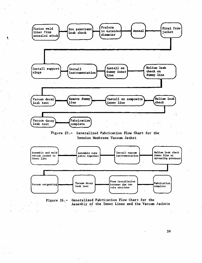
(Fusion weldIliner from.annealed stockHtye penetrant) |
*ak check PH *
) ^
Preformto extendeddiameter
Final form]jacket
[install supportI rings
InstallinstrumentationHInstall on
dummy innerline
Helium leakcheck ondummy line
[Vacuum decay /RU.eak test J yi
Removeiine
Install on compositeinner line
n /He
J ^ch
lium lealcheck
0Vacuum decayleak testFabricationcomplete
Figure 25.- Generalized Fabrication Flow Chart for theTension Membrane Vacuum Jacket
Assemble and weldvacuum jacket toinner line
:Assemble tubepairs together :Install vacuuminstrumentationHelium leak checkinner line atoperating pressure
Vacuum outgassingJVacuum decayleak test
Ji'-|bFoam installationbetween the twotube sections
iFabricationcomplete
Figure 26.- Generalized Fabrication Flow Chart for theAssembly of the Inner Lines and the Vacuum Jackets
59

Figure 27.- Peeled and Unpeeled Resistance Welded Liners, 5 cm (2 in.) Diameter
Figure 28.- Resistance Welded Inner Line Liner, 38 cm (15 in.) Inconel 718
60

I
3 4 * 2 ^u d *j K *H3 S i w
ua - S S Si B .3 gO -H 00 O(0 ^4 *Q U
>£- g"•O r^ 3 WV S V ^•O U C « -H.H O « M
3 (N C O ffl
e - " H SOh • ki ^H•H O t-( « Oa S v e3 -H 4J -H iH
U- ,J V J «
•O •« e•a u
Co
! U
v c,u oat u

« « B•O M O•-tO4) (0 s0
CO 0)M C '_ . _
• r* -rt Q) Q) o.E M ^N
o *n
*O Uv 0•v M• H O4) (B <
• eoo o ~rt O CM
C S - C w 4> .
•H 3 « So0> O B CO 4 W3 4 M ^H -H C
C*. > pj ^ O M C
I
• o.e g - e u a e o S To a u - r f O I B b u u•H 3 O B O V 3 B
to £ a. eW O O
i O -H O OH > SB
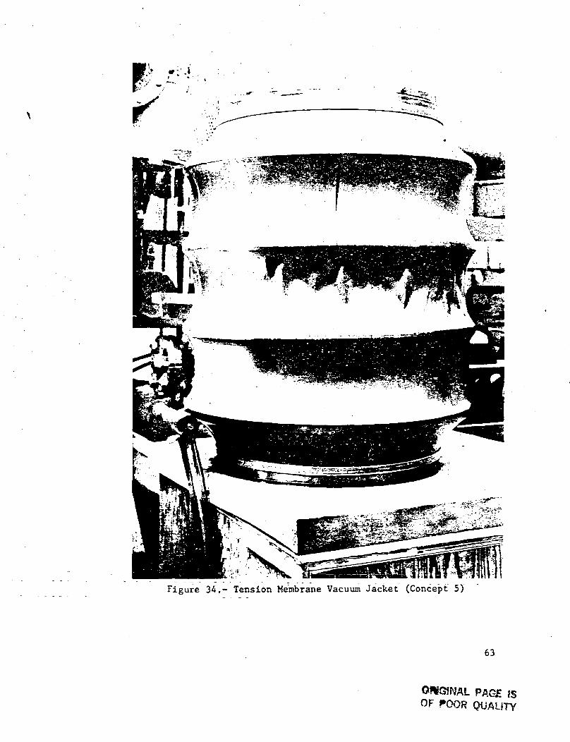
Figure 34.- Tension Membrane Vacuum Jacket (Concept 5)
63
QJISGJNAL PAGE ISOF POOR QUALITY

Deslnd convoluteheight
.Expansion devicerun* through center
Side view
-Mandrel fully expanded
Six piece mechanicallyexpanding mandrel Front view
Handrel fully contractedcontracted —j
nfPi/
r— Convolute edge radius matched by radiuson external finishing wheels
Internal finishing wheel matchesradius of convolute inside theliner
Liner Slight clearance-
Figure 35.- External Convolute Formation Tools
Desiredconvolute —n(Upth
-Intarnal mandrel machined with desired number,shape, and spacing of convolutes.
-Forming uheel machinedto desired convolute shape
Liner
More Chan too does convolute depth thus permitting removalof the Internal mandrel
64
Figure 36.- Internal Convolute Formation Tools

0)oc
tr0)
C/3
60
•H60
•8
co•HCOc0)H
65

Figure 38.- Rings Installed in Tension Membrane VacuumJacket (Concept 5)
Figure 39.- Tension Membrane Vacuum Jacket Welded to CompositeInner Line (Concept 5)
66

Temperature
°F K
350r- 450,-
250
150
50
- 400
350
300 I I I I I I I I I I I2 4 6 8 1 0
Time - hours
Figure 40.- Overwrap Cure Cycle for Inner Line
Temperature
°F K
250-
150-
50-
t»5U»
400
350
300*~ (
' ' i ' i ' i f '3 2 4 6 8 1 0
Time, hr
Figure 41.*- Overwrap Cure Cycle for Vacuum Jackets
67

\-
Figure 42.- Composite Inner Line with Center Support Pad for VacuumJacket Standoff
68

69

70

Figure 46.- Internal Hoop Support Installation (Concept 3)
71

Figure 47.° Segment of Composite I-Beam Shaped Standoff
Figure 48.- Typical Aluminized Mylar Installation
72

Figure 49.- Test Specimens Welded Together with WeldedEnd Caps
73

TESTING
The objectives of the test program were to verify the capa-bility of vacuum jacketed composite lines to meet design require-ments of structural integrity and vacuum maintainability. Toaccomplish these objectives, the test items were subjected tothe test programs defined in Figure 50. Testing was performedaccording to the test plan and in accordance with detailed testprocedures. A description of the tests, test results', and cor-relation with analytical results are presented in this section.
Test Item Instrumentation. - Each of the test items were in-strumented to provide biaxial strain measurements of both theinner line and vacuum jacketed liners. The strain gages werebonded to the inside of the liners after overwrap. Thermocoupleswere mounted under the last layer of overwrap on each compositesection. The location of the strain gages and the thermocouplesare shown in Figure 51. .Additional thermocouples were installedon one of the test items to measure the temperature gradientacross the various layers of overwrap.
Summary of Test Results. - Testing was performed at theMartin Marietta Corporation, Denver Division, Engineering Propul-sion Laboratory from July through August 1973. A summary of thetest results is provided in Table XV.
Inner Line Leak Tests. - The purpose of the leak tests was toverify the integrity of the test items before overwrap, and afteroverwrap and cure. The inner line leak tests were performed be-fore the installation of the vacuum jacket by pressurizing theinner line internally (with the aid of a leak test fixture) tooperating pressure with gaseous helium, and then using a heliummass spectrometer probe to detect any external leakage. The leaktest data is recorded in Table XVI.
Vacuum Decay Leak Tests. - The vacuum decay rates of the vacu-um jacket annul! were measured at the beginning of the test pro-gram and after each major test. The tests were performed byevacuating the annuli, closing the vacuum isolation valves, andmonitoring the change in pressure level with respect to time.The vacuum decay rates thus obtained are provided in Table XVII.
The purpose of the vacuum decay leak tests was to provide abasis for assessing the integrity of the vacuum jackets and innerlines after each major test. As noted in Table XVII, the serialnumber F test item experienced a significant increase in vacuumdecay rate indicating a failure in the pressure surge test. In-spection revealed .an inner line leak. Failure of this item isdiscussed in the pressure surge cycle test section. Minor changesin the leak rate are attributed to test repeatability tolerancesplus test facility variances.
74

3V.ua:
O
>•a:
s
,_}
u:
•—f
_
Cj;
ji.
u
a
CJ
CO
<
lQ)
JDEZ
CD
v.-
r*s ''""*•s-'
<*"> m»™t X— '
fi m-H~
m in^-t \— -
y-srn in
s~*n m-H ^
^-s
^J s, ^
J^^co m(*V i— 1
S r
co mf) ^H
N-'
•oo in
S_^
oo infi ^—i^
^ .CO IT,C) i-
N^
/—N
oo in
^-*
E Cv-x
O
,— I -
C•H
Ecz
CM
O
o ^^x o
•H
85hi
o c• C -H
O -H iH
•H ree>- £>0) -H4J WX
•H U]
01-3- iH iJ
to 3C *H1- O01 >•u C
~ T C Ot-j (J
01CM -H U
tO 3C M^. Q
01 >
•u CCM X O
t£ U
•oO.
co Eaaio
CO V4CJ
in 01c co re•H U
c Ein o) o>
H E
CM 0)t—1 JJto 3C — 1W O01 >u C
CM X Ou u
cu cX CE -H3 ±JC CL
a o01 wO O)c o0
\OinCM
Ol
3OOiH .
» re
0)i-Hu
CJm
tjv • inCM CM00 1
0
•o0!
•H U•H 10to x
4J
u 301 ow? XO JJre 1-1• 5 3
in 01CM ^H
1 U
o cjo oCM •» -O.H CM 01
M -tre re03 "J
01CM iH
•H • Om >,
omCM
i— 1 *-l 1*sO
in o>CM iH
1 U
O CJr^ CM x-\
in • CM -ar~ -* in CM o)
00 i— 1 '-' ^H6C -Hre o
CO U-,
•o"to "K "o
X kl *-x •— 0) O
EX X E3 0) 0
. 3 - - ->,- . — 01o c re >,z •-!to o u k> u> t-i 01 re •• x
AJ -U' C Ol" W•H -H - CDre CD E E a en•H -i 3 T-I re i-l 01JJ 3 3 -H »J <0 iHi-l CT U Ol -^ ^ CJco re to « >>
i— ' re > cu o wo
o
•H V N
CM x-s• CM
L-! CMi— 1 *-*
co o o oCM i-H -* \O *O•-I i-H i-l CM x^ 0)
• CM i-Hin CM *l-l >-x O
)
m o oCM iH f-H^H X.
OJ
O
CM ^<y\ • CN
m CNI»H >"-•'
0 <-< • O *0f-t \£> a>r-l . • CO -H
Csl i-H CO-t s^ U-
OJ /*-sO O vO • <Nr- IH «H m <N
^H '"w'
oO -H
CO m0) -o X
M i— 1 Ut to *X 0 X • £0 T3 01
= i o ~ a - r t ' " ~ 3 . ! * au • to re
• U J - C D O • 0 1 > - l
(0 to o 4J CO C *OO - 0 0 0 1 O O ) O - Hoi o 01 a 3 ai .c at j C - o O - O - H I - I O -
4J O 1-1 tO >-x
3 0 ) 3 0 1 3 W > U r » J3 0 0 3 - H O 3 O 1 O I EO k i O J D X O C i - > Or e 3 r e E i - i t o e x —> U 5 > < C J > i - l W Z
Co41C
1-11-1
01cc
-K
75

TABLE XVI. - INNER LINER LEAKAGE DATA
Design concept
External j
Convolute I
Tension j
Membrane 1
Internal Hoop j
Supports '
External >
Convolute '
Internal j
Convolutes '
External)
Ribs 1
Serialization
f A
1 B
i D
!E• F
f G
1 H
1 :
1 J
J K
1 L
Leak rate
1.3 x 10⁻¹⁰ sec/sec
<1 x 10"10 sec/sec
1.9 x 10~5 sec/sec
2.2 x 10~5 sec/sec
<1 x 10~10 sec/sec
<1 x 10~10 sec/sec
<1 x 10~10 sec/sec
<1 x 10~10 sec/sec
<1 x 10~10 sec/sec
1.01 x 10~6 sec/sec
1. 7 x 10~9 sec/sec
6.78 x 10~5 sec/sec
TABLE XVII. - VACUUM DECAY DATA
Vacuum decay rate (u/hr, except as indicated)
Tubeserialnumber
A-B
B .
C
D
E-F
F
I-J
Baseline
85
1
5
240
93
Poststraincycle
70
1
9
125
123
Post pressure surge
16.6 .
12
0.07 N/cm2/sec(0.1 psi/sec)
140
Postacoustic
60
20
148
76

Vacuum Acquisition and Maintenance. - The purpose of thevacuum acquisition and maintenance tests was to demonstrate thecapability of the vacuum jacketed composite lines to meet cur-rent state-of-the-art vacuum maintenance criteria. The vacuumcriteria for the Saturn cryogenic feedlines was a maximum vacuumlimit of 100 v and a 5 p/day allowable rise rate. This criteriawas adopted for evaluation of the vacuum jacketed composite lines.
Because of the outgassing potential of the instrumentation wir-ing in the vacuum annulus, and of the long time duration re-quired for bakeout and vacuum decay measurement, the vacuumacquisition and maintenance testing was performed on only one ofthe test items. The test item selected for this testing con-sisted of a 20 cm (8 in.) diameter vacuum jacket with a 0.03 cm(0.012 in.) thick liner. This vacuum jacket was fabricated toreplace one of the vacuum jackets that had failed in initialevacuation. A 13 cm (5 in.) diameter composite inner line wassalvaged from the failed test item to make up the vacuum jacketedline assembly. The composite surface of the inner line wascleaned with freon and all instrumentation wiring was removedbefore assembly. After welding, the vacuum jacketed line assemblywas leak tested by connecting the helium mass spectrometer to thevacuum annulus and placing the line assembly in a helium filledplastic bag. No leaks were detected.
A series of six vacuum acquisition and decay tests were per-formed with changes being made to the test setup between tests asshown in Figure 52. The data from these tests is provided inTable XVIII. Significant improvements in vacuum decay rate wereachieved by the changes in the test setup, but the data was notconclusive. The decay rate of 9 p/day was suspected to be largelydue to system leakage.
Leak tests were repeated and a leak was discovered at thepoint where the vacuum gage plug screws into the vacuum sourcetube (Fig. 52). This leak was repaired. In order to determine ifthe vacuum decay rate was caused by system leakage or outgassing,the tube assembly was placed in a vacuum chamber to"eliminate thedelta pressure across the vacuum jacket. Thus, by controllingthe external environment to a pressure near that of the vacuumannulus, the potential for leakage was eliminated and all pres-sure decay could be attributed to outgassing. The tube wasevacuated to 12 p and decay rate was monitored for eight days.The results of this test are plotted in Figure 53.
As noted from Figure 53, the decay rate was insensitive tochamber pressure, indicating that all system leakage had beenrepaired. After the fifth day, the decay rate became less than•the 5 p/day allowable. By the eighth day, the decay rate curvewas becoming flat and it appeared that the outgassing was aboutto stabilize well below the 100 p limit.
77

^*H
/*N
HCOw
£CJu0
Q
5
2O
EHr-lCOt^^
§•CJ
s»— 1
£3fj
^*
^1
M
X4)
f^Mj
H
CflCO1-1cn3
r-t
O
Coo)-oco
•Hcncn3Ocn•rlQ
CO >,O CO01 "O-a ~-E ^3 •3 01U 4-1
CO CO> VJ
U
C >%O CO -•H O ^-v4J Q) 4-1
»J 013- e E
•O 3 0)3 M
4J O 3Cfl CO cn0) > COH 0)
E
i-l0) 3.
Q) .rH T3
01E >3 013 i-lU .CCO O> fl
M.C
1a e o)3 O i-l
P-l *O 4J
4JCfl •CD OH Z
E33 C •o 3 eCO O O> *O *H
1 4 - 1 •oi a 1-1 oi
•O E CO 4-1•H 3 -rl CO> PM 3 rlo cr)-i O >,o. • co ca
>-, CJ4J 4-1 e <uo -H .3 -aC r-l 3
•H CJ 0)T3 J3 cfl C•rt CO > -rl•a a. r-i
CO 0)>, U I-l 4-14J 3 r!•r io.cn oorH 3 en 1-1•rl M Cfl CflU U >-iCO O 0 J-i
tU rH JJ CO
<^^ *^2 r-l
^*^^ OZ -»
\O vO* •
O O
'tu 'aT)H I-l
3 3 '4J 4-1 4-14-1c a e co0) >-i 01 h•rt 0) i-l OJ
•i g- -i §•-* co ai r co oiCN - 4-1 CN ^ 4-1
i-l CM
1CO01J • O
E 4J
01• 4-1 0)
oi cn >co cn 4-1(-1 1-1 •
oi cn oiX J= C 4-1CO 4-1 0) COu cn v*01 C•a 1-1 o x
O cfl01 T3 4J CJCO) 0)
•rl 4J 0) T3r-l O 00
0) cfl 0)4-1 a. oo cJG cn 1-100 3 E E•rl Cn 3 VJ
CO 30)I-l 0) O 4J4-1 00 Cfl 0)
CO CO > T3
p*.CN
CNCN
cncnoo
4JCO
C0) /-s> •** fnO £4 o
o Oe oo m
\o 1-1 cn i-Hc* ~m~
cn
rHrH
E -H<U 4J4J COcnX 0)cn oo
cdC y*
' -rl CO0)
T3 rJ
0)4_)
Ooi -a0. 0)cn oo3 C •cn to -a
£ 0)01 CJ 4-100 UCO CX 01^ 3D.cfl 4J cn0) O) 3
^3 co cn
CN rH<• cn
^f ^fCN CN
OVO rH
a))43
4J 4-1c to(U rli-l 0)ja a.E Ecfl 0)
cn ^ 4J I-H
sr m
•a. CD3 004-1 Cfl0) s^
C/3 CO0)rH
•
X "OCO 0>o oQ) 3
T3 T3OI
0) )-iC
•H 4-1rH C
014-1 Qr* Q)oo >
•H 0cfl )-ii-i a.4-1 E
CO -H
cy*
vO
CN
4-1cfl
c0)^ "^O M
oC CO
oo -ri cn«3- ^ cn
vO
s*^Czj
0
0
rH
"
78

To verify the conclusion of the decay test previously dis-cussed, the tube was baked out again and the decay test was re-peated. The bakeout- was at 359K (187°F) for 24 hours and the decaytest was from 0.5 p to 210 v in 82 days at an average rate of2.56 y/day (Fig. 54). As in the previous decay test, the tubewas placed in a vacuum chamber to allow study of leak rate versusexternal pressure. Again, the decay rate was relatively con-stant at external pressure of 610, 200, or 1 torr, confirming thetube to be leak free. The decay was therefore, caused by out-gassing, probably of one of the cleaning solvents. Most solventsvaporize at approximately 100 torr (100,000 y) and the decay testwould have to be continued indefinitely to reach this pressureand prove the outgassing source.
It was concluded that the vacuum jacketed tube had negligibleleakage and an outgassing rate of 2.56 u/day. It was alsoassumed that the outgassing was due to residual solvents thatcould be eliminated by more extensive bakeout.
Strain Cycle Test. - The objective of the strain cycling testwas to verify the structural integrity of the vacuum jacketedcomposite lines while being subjected to thermal and internal pres-sure stresses expected during the launch and boost phases of theSpace Shuttle mission. The test items were subjected to the fol-lowing sequence:
1) Prechill inner lines by filling with liquid nitrogen.
. 2) Drain inner lines and fill with liquid hydrogen.
3) Pressurize the inner lines to operating pressure'69 N/cm2
(100 psi) for the 38 cm (15 in.) diameter lines and 42 N/cm2
(60 psi) for the 13 cm (5 in.) diameter lines.
4) Drain the liquid hydrogen.
5) Warm to room temperature by flowing hot gaseous nitrogenthrough the inner lines.
The test was performed on test specimens A-B (external con-volutes); C-D (tension membrane), E-F (internal hoop supports)and I-J (internal convolutes). A vacuum was established in eachof the vacuum jackets except E-F, which was back filled withC02 to 8.1 N/cm
2 (11.8 psi) absolute for- cryopumping evaluation.The test setup is shown in Figures 55 and 56.
79

The test was terminated after 26 cycles because of problemsexperienced with the vacuum bags over the composite vacuumjackets. After repeated cycles, the vacuum bags accumulatedmoisture and lost vacuum integrity. The A half of the A-B testspecimen experienced a vacuum jacket buckling failure for thisreason. After this failure, the test was continued with the Bhalf.
Strain Data Correlation. - Strain data was recorded for boththe inner line and the vacuum jacket during strain cycling tests.The actual inner line liner hoop strains averaged 1900 ucm/cm at69 N/cm2 (100 psi), whereas the predicted hoop strain at thispressure is 4150 v-cm/cm. Although the strains appear to be in-comparable (by a factor of 2.2), they merely reflect the con-servative philosophy used during design and fabrication. Theinner line liner axial strains exhibited a similar relationship.
The predicted inner line liner strains were calculated bysectioning the inner line as shown into a free body.
The total force due to pressure acting on the free body (F)is equal to the pressure (P) diameter (D) length (L) and mustbe balanced by the forces exerted by the liner (F ) and the over-wrap (F ) . L
o
F = F + FT = PDL
80

Considering the liner and overwrap individually
•«~ <s) • iff 'Fo FL " ''Therefore SQ = T *"d SL - —-
or F = 2S t L and FT = 2S t Lo oo L L L
Substituting into the force equation above:
PDL = 2S t L + 2ST tT Lo o L L
By definition, the modulus of elasticity (E) = Stress (S)buirdin \Q)
or S = Ee
Substituting into the PDL equation:
PDL = E e 2t L + ET 6. 2t7Lo o o L L L
But e = e because the overwrap and liner are bonded and mustO L
move together. Setting e = e and rearranging yields:O Lt
e =ET 2tT + E 2tL L o o
Substituting actual values and solving:
69 x 38(20 x 10*) (2) (0.013) + (1.1 x 10b) (2) (0.0508)
e = 4150 pcm/cm (hoop)
In conclusion, the strain cycle test results reflect adequatestructural margin when the vacuum jacketed composite lines aresubjected to operating pressures at cryogenic temperatures.
81
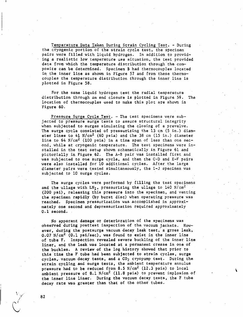
Temperature Data Taken During Strain Cycling Test. - Duringthe cryogenic portion of the strain cycle test, the specimenpairs were filled with liquid hydrogen. In addition to provid-ing a realistic low temperature use situation, the test provideddata from which the temperature distribution through the com-posite can be determined. Specimen B had thermocouples locatedin the inner line as shown in Figure 57 and from these thermo-couples the temperature distribution through the inner line isplotted in Figure 58.
For the same liquid hydrogen test the radial temperaturedistribution through an end closure is plotted in Figure 59. Thelocation of thermocouples used to make this plot are shown inFigure 60.
Pressure Surge Cycle Test. - The test specimens were sub-jected to pressure surge tests to assure structural integritywhen subjected to surges simulating the closing of a prevalve.The surge cycle consisted of pressurizing the 13 cm (5 in.) diam-eter lines to 41 N/cm2 (60 psia) and the 38 cm (15 in.) diameterline to 64 N/cm2 (100 psia) in a time span of less than one sec-ond, while at cryogenic temperature. The test specimens were in-stalled in the test setup shown schematically in Figure 61 andpictorially in Figure 62. The A-B pair was installed first andwas subjected to one surge cycle, and then the C-D and E-F pairswere also installed for 10 additional cycles. After the largediameter pairs were tested simultaneously, the I-J specimen wassubjected to 10 surge cycles.
The surge cycles were performed by filling the test specimensand the ullage with LN2, pressurizing the ullage to 140 N/cm
2
(200 psi), releasing this pressure into the specimen, and ventingthe specimen rapidly (by burst disc) when operating pressure wasreached. Specimen pressurization was. accomplished in approxi-mately one second and depressurization required approximately0.1 second.
No apparent damage or deterioration of the specimens wasobserved during posttest inspection of the vacuum jackets. How-ever, during the postsurge vacuum decay leak test, a gross leak,0.07 N/cm2 (0.1 psi/sec), was found to exist in the inner lineof tube F. Inspection revealed severe buckling of the inner lineliner, and the leak was located at a permanent crease in one ofthe buckles. A review of the log history showed that prior tothis time the F tube had been subjected to strain cycles, surgecycles, vacuum decay tests, and a C02 cryopump test. During thestrain cycling and surge tests, the ambient temperature annuluspressure had to be reduced from 8.5 N/cm2 (12.3 psia) to localambient pressure of 8.1 N/cm2 (11.8 psia) to prevent implosion ofthe inner line liner. During the vacuum decay tests, the F tubedecay rate was greater than that of the other tubes.
V
' / 82
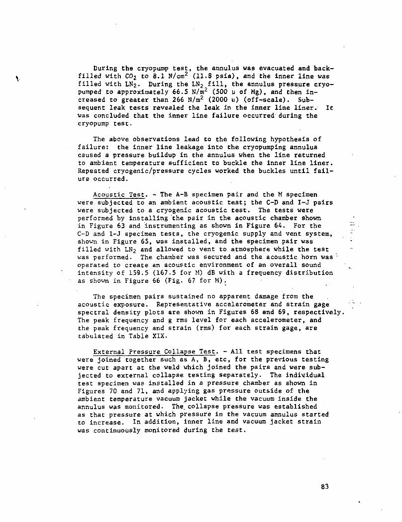
During the cryopump test, the annulus was evacuated and back-filled with C02 to 8.1 N/cm
2 (11.8 psia), and the inner line wasfilled with LN2. During the LN2 fill, the annulus press.ure cryo-pumped to approximately 66.5 N/m2 (500 u of Mg), and then in-creased to greater than 266 N/m2 (2000 w) (off-scale). Sub-sequent leak tests revealed the leak in the inner line liner. Itwas concluded that the inner line failure occurred during thecryopump test.
The above observations lead to the following hypothesis offailure: the inner line leakage into the cryopumping annuluscaused a pressure buildup in the annulus when the line returnedto ambient temperature sufficient to buckle the inner line liner.Repeated cryogenic/pressure cycles worked the buckles until fail-ure occurred.
Acoustic Test. - The A-B specimen pair and the M specimenwere subjected to an ambient acoustic test; the C-D and I-J pairswere subjected to a cryogenic acoustic test. The tests wereperformed by installing 'the pair in the acoustic chamber shownin Figure 63 and instrumenting as shown in Figure 64. For theC-D and I-J specimen tests, the cryogenic supply and vent system,shown in Figure 65, was installed, and the specimen pair wasfilled with LN2 and allowed to vent to atmosphere while the testwas performed. The chamber was secured and the acoustic horn wasoperated to create an acoustic environment of an overall soundintensity of 159.5 (167.5 for M) dB with a frequency distributionas shown in Figure 66 (Fig. 67 for M).
The specimen pairs sustained no apparent damage from theacoustic exposure. Representative accelerometer and strain gagespectral density plots are shown in Figures 68 and 69, respectively.The peak frequency and g rms level for each accelerometer, andthe peak frequency and strain (rms) for each strain gage, aretabulated in Table XIX.
External Pressure Collapse Test. - All test specimens thatwere joined together such as A, B, etc, for the previous testingwere cut apart at the weld which joined the pairs and were sub-jected to external collapse testing separately. The individualtest specimen was installed in a pressure chamber as shown inFigures 70 and 71, and applying gas pressure outside of theambient temperature vacuum jacket while the vacuum inside theannulus was monitored. The collapse pressure was establishedas that pressure at which pressure in the vacuum annulus startedto increase. In addition, inner line and vacuum jacket strainwas continuously monitored during the test.
83
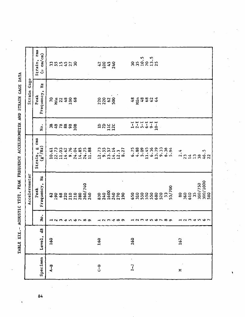
u
HCO
aswH
wua
Ifa
HCOWH
Hco
X
5H
Q)00COacCOM4-1CO
0)4-J
0>So<u<uCJO
!?C ~B
•H yCOw ^i•U Su/CO
NX
-^ ocfl C<U <Ua, s
cr
0a
enaOO'N
cTc^
CO ^
CO
N
*
^s/ OCO C0) 11)P-, 3
O"0)
*O2
n•a
r-lOJ
<u
d
•HCJ0)P.
CO
m mcommin r^o CMOUIO o m c D O c n mCO if\ T— f -*^ CM CO *^ O "^ *^ CO CO i— 1 r . iH CM
r-t CM
O C C M O O O O O O O C M O O O C O O O O C M < tf * *H CM f CO vO CM CM VO CO ^^ *H ^T vO vO vO
i; iH CM CM m S
03 03 CO M PO CO Q a U O I l l l l lC O ^ t r ^ - O O C T i O rH CM r- (CM i— 1 CM in vO CTi O
iH l-l <H , r-l
3 S 3 3 £ o - S £ 3 ^^ [nS^^ ^ S S S ^ S S ^ S <rO C M ^ ^ - 0 > v r ^ - < 3 - r H C M < y , C O < - C M O O v O - * i n r H M 3 C O C ^ v O U - ) C M C O ^ r f O C O v O C N
oo o o^j- o m Or» o !*» <~*^ O Is* ^> ~^-
e N Q o o o o o o o o o o o o o o o o o o o o o c o ^ o o o m o o o
r-t C M C M C M C M C M C M oo <N i— i CM CM i— ( v o c o m m m v o m in c^>\o c o r o m
Hes i cos t i nvo r - coc^ H CM en » oo ox ^ c N c o < - m v o r - o o o > r H c M c o ^ r m v o ^
O o o r sH _ i ^^ _jf"H ^^ ^^
CQ a "7i i t „< u *-* s
84

The B, D, and J tubes successfully withstood an externalpressure 15.2 N/cm2 (22 psi) greater than annulus pressure forfive minutes. The C tube failed at 12.4 N/cm2 (18 psid) due to anaxial compression failure of the inner line. Photographs of theC tube after failure are provided in Figures 72 and 73. The Itube failed at 15.2 N/cm2 (22 psid) while being pressurized to24.8 N/cm2 (36 psid) due to implosion of the jacket liner.
It was concluded from these tests that the tension membraneconcept (C and D) will withstand the design external pressurewhen supported externally in the axial direction, as they wouldbe in a normal application. The glass overwrap concepts (B, I,and J) will withstand design external pressure if the nylon bagtechnique is used to transfer the load from the bond to the glass.
85

•H >,C iHO C
O
XaoaTJ
S CO 09en 01
01 <klQ.
2 .a. ua -a ae a u•H a .
I "
01e >H-H 01<9 0) UU r^ Ou a, a° § -HIH a a
•* aCQ H
-S 3 S
9
ON ^M/l t
2C
v^-7
(M
tn
a
*CMf-lCO
*l-tCO
«,-•
€
i*
*
SB
S
£5•Pic
$
« 3"* mCO £
^ 4
CO
CM •co «n
05
S «»
COCO
CO9
0
COCO
CO
®
k
>
0
a01H
86

"8X *Ju 01 «^ .W S3 S S•8" 5
-3 «H e•85"
£&
e
&s« s•fl 3QI a
•SI
87

rt-o
tu
0)0)H
00c•H
COCO
oo4J
O
g
o>I
ro
<u1-1300
88

220
200
180
160
140
120
100
80
60
20
OO
10 20 30 40 50 60Time, day
Figure 54. - M-Tube Vacuum Decay Test (82 Days)
70 80
89

Figure 55. - Strain Cycle Test Setup Showing 38 cm (15 in.)Diameter Tubes
TVl
OPTS
Figure 56. - Strain Cycle Test Schematic
90

T8B (locate between Longo strips)
T8B (locate over Longo strip,Narmco In place)
T8B (locate over Longostrip, tape In place)
T7B (Narmco In place)
T2B
Liner
1st hoop wrap
Longo strip (Intermittent)
2nd hoop wrap (outer layer)
Figure 57. - Thermocouple Location for Inner LineTemperature Distribution
-316
-352-
! -388
-424
-460-1
Figure 58. - Temperature Profile of 38 cm (15 in.) Inner Line (B)
91
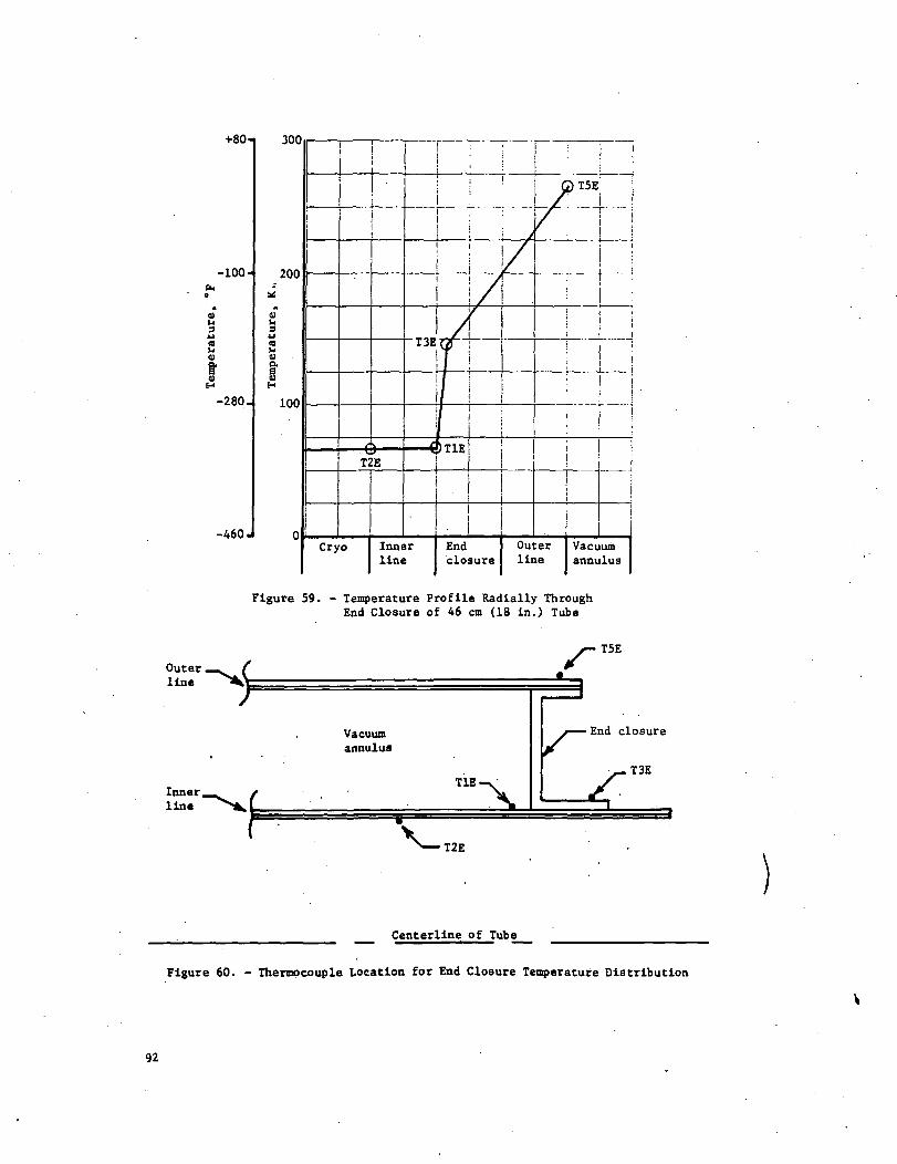
+80'
-100-
Vi<U
-280.
-460 J
300
200
91U
u
2<ua
100
i
T2E
Cryo
1
/
"T3E
/
f,1
1f
Innerline
,m
f
/_
'
i
i
Endclosure
:
G)T5E
/ iY'~^~
\
Outerline
Vacuumannulus
Figure 59. - Temperature Profile Radially ThroughEnd Closure of 46 cm (18 in.) Tube
Outer.line
line
*
f
/-T5E
Vacuumannulus
End closure
y-X-
T2E
Centerline of Tube
Figure 60. - Thermocouple Location for End Closure Temperature Distribution
92

sw
Q
TestItem
Burst disc
[75.8 N/cn2 (1X0 psl) for 38 (15 in.) line]
[48.3 N/cn2 (70 psi) for 13 cm (5 in.) line]
TestItem
LN2
TestItem
UW
GN2 [341 N/cm2 (495 psi)]
UPV
Ullage
SFV
Figure 61.
SPV
- Pressure Surge Cycle Test Fixture Schematic
Figure 62. - Pressure Surge Test Setup
93

Figure 63. - A-B Tube Assembly Installed for Acoustic Test
S9**, SIW
Qk* 0 VT5 ©Sll*. S12*
V Tl <PS5+, S6+©SI, S2
^^"•vw /8 = Vertical f9 - Lateral
LEGEND® Biaxial strain gage
Y Thermocouple
^y Triaxial accelerooeter
1 = Vertical2 - Axial
0 V 3 • Lateral
\ S9**, S10**® Sll*, S12* ©V
<>
Q_S5, S6
© SI, S2
/ / // 6 • Vertical / /__7 - Lateral / "
Z_ 4 =NOTES ' 5 =
+ Except tube K
* Tubes C and D only
** All except tubes C and D
^ <
^X
XXXX
XXj^
XXXX
XXXX
XN^^
J^ .irticalKial
Biaxial accelerooeter
Microphone
Rotate tube pair so all strain gagesare in the same horizontal plane.Tube K also record T2, T6, T7, 18
Figure 64. - Acoustic Test Instrumentation
94

g
<U
•o
aa3
00o
Z-
3tr
COaiH
4J(03OU
C<D000
vO
(U
360
to<uQ
95

MID-FREQUENCIES Of ONE-THIRD-OCTAVE BANDS (CPS)
i170
150
4
O
1'.3?
1
•9
j
IO
a
ovtn
i9
flU.
f
»
2
Lt*
f~\.
V.
a9 91
J-
«o
9 *
5 dB
^
J
•
X\.
9 IOO
•o e
Vacuum
• j-
9 2
Jacke
./-
;
-N-
290
)O 11
t tin
1
L,f
J
9 91
i I/I
'
•\VH
UO
0 •
- 450
•v.•v.
A
1000 1 «00
10 qso 201
-sec Duratic
LV A
2900 •»
9O 1190
n
L
9090
1
U00
L
00ec
•V- t
oooo »o00 9900
00
20i
'
29OOO
MO 311
\
•0000
00 901
0000
loo eotoo«cno
Figure 66. - Typical Input Spectrum (160 dB)
MID-FREQUENCIES OF ONE-THIRD-OCTAVE BANDS (CPS)
iC
160
;jl>I50i
i
»«e
130
1
S
1
HUCMUi*t«S ••
r
a
xm
V
IJ
•J.
r
1
LCV
f
rJ
29
1 H
fc2£l
rij
^-
40
9 >
.5 dB
f \
U MX)
•0 9
/
wo9 2
1
_/
290
M 91
tacuua
J-
400
9 9C
Jack
-v. —r
uo0 •
iced i
- .
1000
>o e
ine M
T f
•00
o 20
60-s
-i1
hv
>900» 1C
ec Dur
1J
4000
0 90
at ion
a00
~V
00K
"\
10000 *000 BMO
0010
29000MO »
1
•000000 90
;
uoK>0
IOO
•0
eo»c>oo
Figure 67. - Typical Input Spectrum (167 dB)
96

O H 00-
• I S - g -3 g 2-szx .
o co *o tn o oo• H O
97

Pressuretransducer
Figure 70. - External Collapse Test Setup Schematic
. •• '•-..-tJHfV -y?-' --^
Figure 71. - External Collapse Test Chamber
98

Figure 72. - Tube C after External Collapse
Figure 73. - Tube C after External Collapse (Inner Line)
99

ANALYSIS OF RESULTS
The design concepts for each major component in the testspecimens produced during this program were analyzed and a recom-mended design was selected. The analysis included an evaluationof materials, producibility, performance, cost, and weight. Adiscussion of vacuum acquisition and vacuum maintenance is pre-sented. The recommended designs consist of a composite vacuumjacketed line, which incorporates optimum components, and thetension membrane vacuum jacketed line. These designs are com-pared on the basis of weight with other existing state-of-the-art and advanced design concepts.
Analysis of Test Specimen Design Concepts. - The major com-ponents and design approaches used in the fabrication of thevacuum jacketed composite lines were evaluated. The evaluationconsidered each of the selected concepts and includes an analysisof the inner line, vacuum jacket, cost, weight, bonding; materials,end closures, standoffs, and vacuum acquisition and maintenance.
Inner line: The selected material for the commodity carryinginner lines was Inconel 718. Inconel 718 has a significantadvantage over other corrosion resistant materials due to itshigh yield strength, 105,480 N/cra2 (153,000 psi) achieved byheat treating. Because of the protection and damage resistanceprovided by composite overwrapping, thin gage materials are idealfor composite tubing. The wall thickness required with internalline pressures of 34 to 297 N/cm2 (50 to 300 psi) for Inconel718 and stainless steel 13 cm (5 in.) and 38 cm (15 in.) diameterlines are compared in Figure 74. The reduction in gage that canbe achieved with Inconel 718 is clearly evident.
For small lines the minimum gage required for internal linepressure is often less than can be reliably produced. Liners of0.008 cm (0.003 in.) thick were found to be very difficult toproduce leak free. Three of the 13 cm (5 in.) diameter innerlines, however, were successfully made with 0.008 cm (0.003 in.)thick Inconel 718. All of these lines developed small wrinklesunder the end fittings during composite curing, and one wrinkledbadly during postcuring. No difficulty, however, was experiencedin producing the 13 cm (5 in.) and 38 cm (15 in.) diameter testspecimens with 0.013 cm (0.005 in.) Inconel 718.
100

Both fusion and resistance welding was used in the fabricationof the test specimens. Fusion welding the longitudinal tubingseam is more desirable in that it results in a smoother innersurface. The resistance welding requires a lap joint. The excessmaterial is peeled away after welding but the result is a smallridge along the seam. Resistance welding, however, is more de-sirable for welding the end fittings. Fusion welding the endfittings results in a discontinuity in the line flow path due tothe required weld preparation area. The flow path can be smoothif the end fittings are resistance welded to the thin lines. Thedifferences in the two welding techniques are illustrated inFigure 75. Both welding techniques are acceptable for structuraland zero leak criteria.
The inner lines were overwrapped with S/HTS glass fibers ina 58-68R resin system. The overwrap consisted of a layer ofmachine hoop wrapped 20 end roving, a half layer of longitudinallyoriented glass cloth and a final layer of hoop wrap. The testspecimens were overwrapped and cured while pressurized to pre-clude buckling. The overwrap and curing operations were performed,with no anomalies. After initial curing, however, the innerlines were postcured at a temperature of 400°K (260°F) while ina vacuum of 0.0013 N/cm2 (10~5 torr) . . The liners were notpressurized during postcure. One of the 0.008 cm (0.003 in.)liners buckled severely during postcure. To prevent bucklingduring high temperature postcure, internal pressurization isrequired.
Although not tested on this program, the use of PRD 49-111 inthe same 58-68R resin system should reduce the composite weightby the ratio of the material densities, 0.002 kg/cm3 (0.085lb/in.3) for S-Glass and 0.001 kg/cm3 (0.055 lb/in.3) for PRD49-111.
Early analysis (Appendix A) indicated that a structural bondbetween the overwrap and the thin metal liner is required forinner line axial load carrying capability. It was found, how-ever, that bonding is not required for the inner line, becausethe delta pressure between the inner line and the vacuum jacketprovides additional structural rigidity. Tests demonstrated anaxial load capability in excess of 2268 kg (5000 Ib) for unbonded38 cm (15 in.) diameter lines.
Vacuum jacket: Test specimens were produced using fivedifferent vacuum jacket design concepts. The five design conceptsare evaluated on the basis of producibility, cost, and weight. Ofthe composite vacuum jackets, the internal convolute design issuperior because of producibility considerations. The tensionmembrane is a structurally sound, light-weight concept, but is themost expensive to produce. A discussion of the evaluation param-eters is provided in the following paragraphs.
101

Vacuum jacket producibility: The three primary areas con-sidered are thin metal liner fabrication, composite overwrap,and assembly. Metal liners were successfully produced in sizesof 20 and 46 cm (8 and 18 in.) diameter from 0.013 cm (0.005 in.)Inconel 718, which were leak free and did not wrinkle during thecomposite curing. One 20 cm (8 in.) diameter vacuum jacket linerwas produced using 0.030 cm ((0.012 in.) Inconel 719. The heaviergage liner had fewer imperfections (tooling marks, etc.) than thethinner gage liners. The tension membrane vacuum jackets weresuccessfully produced by hydrostatically bulge forming 0.046 cm(0.018 in.) thick cylinders and then chem-milling to the finalthickness of 0.0191 cm (0.0075 in.). This fabrication techniqueproved very successful.
The 20 and 46 cm (8 and 18 in.) diameter vacuum jackets wereoverwrapped with two hoop layers of ±0.09 rad (±5 deg) crisscrosswrapping. The overwrap material used was S-Glass preimpregnatedwith Epon 828-mpda resin. This process worked quite well. The±0.09 rad (±5 deg) wrap pattern results in some build up ofcomposite at the ends, which caused some difficulty with one 20cm (8 in.) diameter vacuum jacket that had an internal convolutenear the end for expansion and contraction purposes. The com-posite build up tended to roll over into the convolute and fillit. This, however, was easily corrected by locating the con-volutes 2 cm (0.8 in.) from the ends.
Vacuum jackets with smooth metallic liners were the easiestto overwrap; vacuum jackets with external convolutes were the mostdifficult. The problem with the external convolutes is that theroving tends to slide off the convolute leaving minute areas ofmetal that are not covered. This problem can be eliminated bythe use of wider roving or tape and/or by reducing the wraptension.
The vacuum jackets were fusion welded to the inner linesafter overwrap. The temperature of the composite was maintainedbelow 367 K (200°F) during welding by flowing cold.gaseous nitro-gen through the tubes. Stainless steel tubes, 1.3 and 0.96 cm(0.5 and 0.38 in.) diameter, were welded into the vacuum jacketend closure to be used as vacuum acquisition ports and instrumen-tation feedthroughs. Even though temperature control wasattempted during welding, composite disbonds developed in thevacuum jackets, and end closure warpage occurred because of thewelding heat. It is recommended that future vacuum jackets useresistance welding to reduce heat, and that the vacuum ports bewelded before assembly using welding techniques that will notwarp the end closure flange. Bellows manufacturers have nodifficulty in making these welds.
102

Vacuum jacketed composite line cost: The cost of the vacuumJacketed line assemblies for each of the five design concepts wascompared during concept evaluation in Task I (Table IX). Thisdata did not change as a result of the fabrication and test ex-perience gained on this program. The unit costs are based on aproduction quantity of two each. The cost for producing eachdesign concept for the composite vacuum jacketed lines is essen-tially equal. The cost for the tension membrane concept isgreater than for the composite concepts.
Vacuum jacketed composite line weight: The weight of eachof the composite design concepts was approximately equal. Theweight of the composite designs is compared to the tension mem-brane design in Table XX. For weight evaluation the compositevacuum jacket liner material thickness was based on the thick-ness required to withstand an external pressure of 25 N/cm2
(36.7 psi) without relying on the overwrap for structural support.
Bonding overwrap to vacuum jacket metal liners: All compositedesign concepts involved bonding the overwrap to 0.013 cm (0.005 '*-in.) thick Inconel 718 liners to reduce weight. This conceptproved unsuccessful in that the bond did not develop sufficientstrength to resist loading in peel. (See Appendix D for athorough discussion of bonding failures.) Current state-of-the-art bonding techniques are inadequate for this application. Thus,it is essential that the vacuum jacket metal liners be of suf-ficient strength to withstand external pressure loading withoutrelying on the overwrap. The overwrap, however, is still requiredto provide handling and damage resistance if minimum weight isrequired. A nonoverwrapped vacuum jacket of minimum gage (forexternal pressure) is very susceptible to damage and not acceptablefor flight. The addition of the overwrap provides the requireddamage resistance with less added weight than would result fromincreasing metal line thickness.
Vacuum jacket liner material: Due to the external pressure(buckling loading) the vacuum jacket liner thickness is a functionof material modulus and not yield strength. Thus Inconel 718 hasno advantages over stainless steel for the jacket liners. Stain-less steel is the. preferred material because it is less expensiveand has superior forming and welding characteristics.
The liner thickness is minimized by convolutes that provideresistance to buckling. The required liner thickness for stain-less steel vacuum jackets is plotted as a function of diameterin Figure 76.
103

C/2WaQ
Stj
CJ
2JSSCJ
£>P_JS^COu09•3b35*
1C/J
[MrH
C/4
C/5
eMCAo
c3^
w
1JJ
§^*t
f *^^
H
3S3B
4
Ql"l
1s
<oaiHrH
00CorH
s~\•
fl•H
O«*
CN^*/
su
•
ovO
fl)
•HrH
00flOrH
/-N
*
fl
•rl
^J
<Nv-
su\oCTi
O
CU
H
CUacM
cucCOIH
"e ^CU <-HS N*-/
fl 00o -*iHcafl0)H
0)4J -»iH .Q
O *--
§* 00
5*
4) .
9M
«£) *••>.S »O
§ rHN«
C 00o _*"*iH
COa(0H
0)
•H JOCO rH
o«q J?o
« /-Nrl •fl) C4J 1-1
CO S•H -5•o
yl
^O»
oo0
1 1 rH 11 1 ^ 1
CN•
O>•
<^N x^ y^ x^H r^ m oo
* • • •O\ C*t OO O\
CNJ ON t** ^
CNI r-» CN iHCN) -s^ vO 00
CN|•
o1 1 CM 1
CM
0\
/**v ^V X— ^"N«* oo CM in
r *^ CM c^*-* rH CM CM
"t ^ 'I *^fO \& cO c*^i-i t-i
m o m o• rH rH CM
<o m oo r- 1rH CM CO in
COrl Wl rl rl •cu cu cu fl) co •
V 4 4 J 4 J 4 J 4 J r l C O t - ~01 CU CU CU 0) fl) rl •
9 J « J C O C f l C O f l ) 4 J C OE l H l H l H - r l B g * ~ *
•rl -rl CO • CS•rj / -N ^«^ ^-^ ,_f *rj ^ 0) g
. . . r-| -O CO CJ
• iH iH -H rH rH I-l Z0 M CO rH CO•ri o m o o co m
rH rH CM 4-1 rl T3 CMIT) s-'^-'N^ O rl fl)^^ CO MH O rH 14-1
B S B CO MH rH Og CJ 0 CJ CO 00 -rlO rH rH CO E 00
in 00 rH CJ f» CO 1 CCO CM CO in 1 CO 6 -rlH CO rH rH 0) T3
rl I-l rl fl) U 42 COr ! Q O O / ~ . G 1 CO CJ 0Q L M U - l M - l > O C O r l r Hm fl o cu fl)
***\ x-s /— N «H fl / > 4-1 r; ni/ - % • • • hH • CU 4J )-l
• fl fl fl v£) fl B 3fiiH-rli-l rH ^> -rl CO fl CO
•H O -rl -rl CO-J-vOOO • d O "O 0)
C M r H r H r H O l H C M ^ ^ MH O O O 1 ^ O r H • O ,O . . . in i-H fl• O O O S O O CO -H rH
O>-'>-'>— • CJ O ^ CO^j . LJ in r«^— • M Ut G
SS8 rH o B o r** MS c j o c j -<r ^-* o y-i o cuU O O 4J
vOrHvO • B I - H / - X • Xcoco^- t f o cJ m • o fl)O O O O O C "-'
O O O O r H O B c O f l )a) o m cj MII II 0 II 00 • II • fl 3
SO rH CTl O COa) ^ I-H co
0 0 0 0 0 0 0 0 II 00 O -O 0)
a C O C O C O C . C O S ' C U M000000 CO fl) 00 CJ O C O O ,
rl 00 COrHrHiHrH S CO O , r H II U 3 C J
*J 4J 4-> 4-1 fl) M • fl) CO )J0 ) 0 ) 0 ) 0 ) > rH 3 CO 00 -H CUS S S B O C O r l C O J =
4-1 cu u oo cu aU 4J 4J 4J 4J 0) > O O C O0 ) f l ) f l ) 0 > 0) S O 00 rH cQO
^ ^ ^ flCQOOScj o a 0 cj fl) ai in 4-1 4Jc O c a c O c O CO fl C U cu r H c OTI 1-1 1-1 i-| 1-j iH iH CO B CO
rH i-l O. 4J COB B B B B co cu cu cu3 3 3 3 3 r i IH c SB
01 3 3 3 3 3 CU CU CO CO -HC U O O O CJ fl fl 3 I-l 4J4JO CD CO CO cf l cQ f l BHA f l )•rl > > > > > iH iH 3 B ^>n4J C 0) CJ •
t at cu cu cu o) 0) a) e s co CN4J 4J 4-> 4-> 4J 4-1 4-> CO T->H i H i H - r l i H i H i H f l M
co co co co co co co ca 5 o SoCO O O O O O O O 3 iH 3< 0,0.0.0. o. a, o, 3 ca 3s-*.
g S B B B B S cj c O-HS O O O O Q O O CO 0) C O C O
O O O O 0 0 0 > H >o.
COC D * • • • • • •
f-3 rH CM CO «i in vp f*^
104

End closures: The end closure design used for all compositevacuum jacket test specimens consisted of a 0.109 cm (0.043 in.)channel shaped ring. This configuration was designed to transferall axial pressure loading to the inner line and to transfer theinner line thermal contraction to the vacuum jacket. The vacuumjacket was then convoluted to accommodate the inner line thermalcontraction. This design concept proved successful but is notoptimum for minimum weight or thermal heat leak.
Convair's analysis (ref 4), was used as a basis for selectinga low weight thermally efficient end closure for incorporationinto the composite vacuum jacketed design. The design, as shownin Figure 77, features a bellows section welded to both innerline and vacuum jacket. The bellows is 0.013 cm (0.005 in.)thick stainless steel and provides a tortuous heat leak path.This design, because of the bellows section, does not requirethat the vacuum jacket be convoluted for expansion and contrac-tion. A disadvantage to this design is that a standoff supportis required near the end closure because the bellows is notdesigned to withstand loading normal to the axis of the line.
Standoffs: A composite I-section standoff was used in eachof the 46 cm (18 in.) composite vacuum jackets. This designwas difficult to install and was not optimized for minimumweight or heat leak. The standoff support pad consisted of acomposite ring stiffener overwrapped on the inner line. Tol-erance control on the support pad proved to be difficult, whichcontributed to the installation problems. Thus, the compositeI-section concept is not recommended for future application.Convair, in their vacuum jacketed line technology investigation(ref 4), performed an evaluation of state-of-the-art standoffdesigns. The design shown in Figure 77 proved to be optimum forminimum weight and heat leak considerations. This design wasused on the S-II LH2 vent line and is adaptable for use incomposite vacuum jacketed lines.
Vacuum acquisition and maintenance: During this program thevacuum acquisition and maintenance objectives were met usingtube M. The minimum annulus pressure obtainable was 6 x 10~4
torr and the vacuum decay rate was 2.6 p/day over an 81-dayperiod. The principles of vacuum engineering were used as appli-cable. A discussion of these principles and the various factorswhich must be considered to obtain and maintain vacuum at therequired levels follows.
105

Materials of construction must be carefully selected becauseevery material, when exposed to vacuum conditions, will liberategas to varying degrees by outgassing. Outgassing includes evap-oration, adsorption, absorption, chemisorbtion molecules in solu-tion, and molecules from decomposition of materials. In additionto outgassing, diffusion, permeation, trapped volumes and porousleaks are undesirable material characteristics. In general,materials of closed cell construction with smooth clean surfacesare better in this regard. Stainless steel is the most popularconstruction material. But Inconel, aluminum, brass, and iron areequally acceptable.
Construction techniques should eliminate all possible leakpaths by welding all joints. Threaded seals such as pipe threadsshould not be used. The geometry of the vacuum space should besuch that volumes are interconnected by large passage ways, andvalves and tubes leading to the vacuum space should have as largean internal diameter as possible. Static seals should be metalbellows if possible.
Before the components are assembled, they should be thoroughlycleaned by vapor degreasing or by the use of a highly volatilesolvent to remove oil and other contaminants. Low vapor pressureand volatility are of prime importance in solvent selection.
Assembly of the components should be by 100% gas shieldedarc welding to eliminate flux outgassing. After welding, ahelium mass spectrometer leak check should be made and any leaksshould be repaired.
It is imperative that the annulus be leak free to achieve apressure rise rate of less than 5 u/day. Using the ideal gaslaw, a 5 p/day pressure rise can be translated into an allowableleakage rate for a given annulus volume. For a 38 cm (15 in.)diameter inner line with a 46 cm (18 in.) diameter vacuum jacket,305 cm (120 in.) long, the leak rate equivalent to a 5-M/daypressure rise is calculated as:
PV = WRT
PVw = —-W RT
AIT APVAW = —
AW = (21 600)(300«K) = 1'18 X 10 kg/day (2'61 X 10 lb/day)
1.18 x 10~5 kg/day is equivalent to 1.14 x 10~5 sec/sec.
106

The allowable gas load of 1.14 x 10~5 sec/sec consists ofleaks, outgassing and permeation. Outgassing can be reduced toinsignificant magnitudes by proper bakeout. The equivalent leakrate attributable to outgassing is calculate as 4.8 x 10~10 sec/sec using the methods of reference 5. A leak of 1.14 x 10~5 sec/sec is, therefore, allowed and for reference purposes the sizeof the hole which would cause this leak can be calculated usingKnudsen's Law for molecular flow and the techniques of reference6.
„ .
r _ / QLVg" \ 1/3I 20.48-v/T APJ
= /8.64 x IP"3 x 0.0305 x 29\ i/3
r ^ 20.48 x 293 x 759,900 I
r = 1.52 x 10'1* cm (6 x ID'5 in.)
In conclusion, it is seen that a vacuum decay rate of 5 p/day is equivalent to a leak of 1.14 x 10~5 sec/sec or a singleleak path diameter of 0.0003 cm (0.00012 in.).
Vacuum acquisition of the vacuum annulus begins after assemblyand usually consists of bakeout and pumping operations. The bake-out is usually required to provide activation energy to releasethe trapped molecules (sorbed, dissolved, etc) and the pumping isrequired to remove these molecules. The configuration of theideal vacuum acquisition system is a large capacity, low pressurepump, short-coupled to the vacuum annulus. In the molecularregime, flow in a tube is dependent on rebound in the desireddirection; and is proportional to the diameter cubed and inverselyproportional to the length. In the more familiar viscous regime,flow is caused by differential pressure forces and is proportionalto the diameter squared and inversely proportional to the length.Therefore, in vacuum work, the diameter of the flow passages ismuch more critical than in conventional fluid flow.
Vacuum maintenance is not necessarily limited to continuousevacuation but also refers to the rate of annulus pressure in-crease when the annulus is isolated. The vacuum maintenancerequirement for aerospace use is generally 5 p/day in the rangeof 10 to 100 u Hg. Good vacuum maintenance is directly depen- -dent upon the quality of the previous steps (design and fabri-cation) .
107

Nonmetallics in the vacuum annulus increase the difficulty ofacquiring and maintaining a hard vacuum. These difficulties canbe overcome by proper cleaning and bakeout procedures as was dem-onstrated by the vacuum maintenance testing performed on the M-test specimen, which had a composite overwrap on the inner line.An additional fabrication step may be employed, however, whichshould make the composite vacuum jacketed line equivalent to all-metal lines for vacuum integrity. A thin coating,of aluminumapplied by vacuum deposition over the composite would entrap anyoutgassing constituents. There would then be a zero delta pres-sure across the aluminum coating when the annulus is evacuated,thus eliminating any outgassing from the composite overwrap.This process requires development to determine the requiredcoating thickness and application techniques for leak freesealing, but is considered well within the state-of-the-art ofexisting equipment capability. The aluminum coating has anadded benefit in that it provides a radiation shield over thecomposite and may eliminate the requirement for a layer of alumi-nized mylar required for thermal efficiency.
Recommended Design, Vacuum Jacketed Composite Lines.- Basedon the results of this program, the recommended vacuum jacketedcomposite line is depicted in Figure 78. The design, featuringthe optimum inner line, vacuum jacket, and detail componentsdiscussed previously, is based on a 35.6 cm (14 in.) diameterby 304.8 cm (120 in.) long line for a direct comparison withcurrent state-of-the-art designs and an advanced state-of-the-artvacuum jacketed line. A discussion of the specific design detailsfollows.
The inner line consists of 0.013 cm (0.005 in.) thick Inconel718 liner overwrapped with S-Glass fibers 0.05 cm (0.020 in.)thick preimpregnated with a 58-68R resin system. The liner hasa single longitudinal fusion weld with resistance welded endfittings. The end fittings are stainless steel.
The vacuum jacket is 0.038 cm (0.015 in.) thick 304 stainlesssteel with 0.51 cm (0.2 in.) radius internal convolutes spaced at3.8 cm (1.5 in.) intervals. The convolutes are filled with a lowdensity foam machined to the outside diameter of the vacuum jacketliner. The vacuum jacket liner is overwrapped with S-Glass fibers0.05 cm (0.020 in.) thick preimpregnated with Epon 828-mpda resin.
The vacuum end closures feature a stiff design at one end ofthe line and a flexible bellows at the other end. The stiff endclosure is resistance welded to the vacuum jacket liner and eitherfusion or resistance welded to the inner line end fitting. Vacuumcomponents consisting of vacuum acquisition valve, vacuum gage,burst disc, and inner line instrumentation port are installed inthe end closure. The flexible bellows type end closure is fusionwelded to both the inner line and the vacuum jacket and allows theinner line to expand and contract without transferring axial loadinto the vacuum jacket.
108

The standoffs are spaced at 60.4 cm (24 in.) intervals andconsist of 12-sided teflon rings that are slipped over the innerduct and retained in place by 0.153 cm (0.06 in.) L-brackets oneach side.
State-of-the-Art and Advanced Vacuum Jacketed Line Designs.-The Convair Aerospace Division, in their Vacuum Jacketed DuctingTechnology Investigation (ref. 4), performed an analysis ofexisting state-of-the-art vacuum jacket designs. These designsare depicted in Figure 79 and described in the following para-graphs. All designs were scaled-up to a typical common 35.6 cm(14 in.) inner line diameter. The inner line material is 321stainless steel of 0.152 cm (0.06 in.) wall thickness. Thevacuum jackets are designed for an external pressure loading of25 N/cm2 (36.7 psi).
Design 1 - S-IVB Main LH2 Supply Duct (Obsolete): A 1.587 cm(0.625 in.) vacuum cavity filled with glass-fiber of 64.08 kg/m3
(4.0 lb/ft3) density is enclosed by an 0.040 cm (0.016 in.) 321stainless steel shell. This shell has 1.27 cm (0.5 in.) high Iconvolutions on 2.54 cm (1.0 in.) centers to provide longitudinalexpansion and contraction. The convolutions also provide support1
for externally applied loads.
Design 2 - S-IVB and S-II Main LH2 Supply Ducts (CurrentDesign): A 0.723 cm (0.285 in.) vacuum cavity is enclosed by a •0.051 cm (0.020 in.) 321 stainless steel shell. This shell has0.553 cm (0.218 in.) high square convolutions, 2.8 cm (1.10 in.)wide on 2.8 cm (1.10 in.) centers.
Design 3 - Centaur LH2 Supply Duct: A 1.905 cm (0.75 in.)thick Freon blown polyurethane foam of 64.08 kg/m3 (4.0 lb/ft3)is the basic insulation. Approximately 30% of the foam isremoved by scalloping. The foam is covered by a five layerblanket-type aluminized Mylar/Dacron radiation shield.
Design 4 - S-IVB LH2 Recirculation Line: A 1.27 cm (0.5 in.)vacuum cavity is enclosed by an 0.356 cm (0.14 in.) 321 stainlesssteel straight shell. The inner duct is wrapped with two alter-nate layers of 0.005 cm (0.002 in.) aluminum foil and 0.02 cm(0.008 in.) Dexter paper.
: Design 5 - S-II LH2 Vent Line: A 1.27 cm (0.5 in.) vacuumcavity is enclosed by a 0.254 cm (0.10 in.) 321 stainless steelshell. The shell has 0.965 cm (0.38 in.) high convolutions oh "11.43 cm (4.5 in.) centers.
Convair's parametric evaluation shows Design 4 having thehighest performance rating based primarily on excellent thermalperformance and reliability.
109

In addition, Convair performed an evaluation of advancedvacuum jacketed line design concepts. A design concept whichpromised the most favorable performance characteristics, wasselected for design fabrication and test. The design consistsof a straight section of vacuum jacketed duct 35.6 cm (14 in.)diameter by 305 cm (120 in.) long (Fig. 80). The Standoffs arelocated 76 cm (30 in.) from each end and consist of eight 0.64 cm(0.25 in.) radial tubes welded to the inner line.
The outer vacuum jacket consists of a stainless steel innershell 0.064 cm (0.025 in.) thick with a fiberglass honeycombmaterial (Hexcel HRHIO-OX-3/16-3.0) which is an overexpanded,flexible honeycomb. Attachment of components to the jacket ismade by means of an end fitting as shown in Figure 80. Thevacuum jacket end closures consist of a bellows nested withinthe outer jacket.
The description of these designs is included here to providedata for weight comparison with the composites and tension mem-brane vacuum jacketed designs.
Tension Membrane Vacuum Jacketed Line. - The tension membranevacuum jacketed line as depicted in Figure 7, is scaled to a 36cm (14 in.) diameter, 305 cm (120 in.) long line for a directweight comparison with other design concepts. The design featuresa composite inner line and standoffs on 61 cm (24 in.) centersidentical to that shown in Figure 78. The tension membrane is0.0191 cm (0.0075 in.) thick stainless steel having a minordiameter of 38 cm (15 in.) and a major diameter of 43 cm (17 in.)with a bay length of 10 cm (4 in.). Each bay is supported by analuminum hoop ring.
Weight Comparison of Vacuum Jacketed Design Concepts. - Therecommended composite and tension membrane vacuum jacketed linesare compared on the basis of weight with the state-of-the-artdesigns and advanced design concepts defined in the precedingparagraphs. The weight comparison is based on a 36 cm (14 in.)diameter 305 cm (120 in.) long line for each design concept.
A comparison of the weights of the different design conceptsis provided in Table XXI. The tension membrane concept is thelightest with the composite vacuum jacketed line concept next,behind. A major contribution to the weight of the state-of-the-art and the advanced designs is the inner line. The gage of theinner line could probably be reduced to about 0.102 cm (0.040in.), which would save approximately 15.1 kg (33 Ib) for theseconcepts. The inner line weight for these designs, however, isstill significantly heavier than the composite inner line weight.
110

os
5oCN
Eu
oen
ccsg2o
ss8
S2
tozJ
JD
CD
4J.CDO•H
OJ
Com
pone
nt w
X
0
[1*
u
Q
U
m
*
Uu
.9
| D
esig
n C
CO C*l ^ ^* ^^ vO
-H O *H • OON -31 CM CM •& vO
^ I I ^ J S ^ j ^ | . w ^
i-l OD ^ iH CM CM<r —t r-.
CO NO <T CM O
*•" 1 1 -H 1 1 I 1 CM1 1 ^ 1 1 1 1 *-'
-a-' *•*• CM
00 ON f«- -tf CM O
ON CM w N~- *— • ,Hv-* i i CM I i I 1 m
i i — ' i I I I •**
i— 1 "H O •-( *O <£><s o ^
OO sO *»
^H 00 OON N-' O
^ ! I i i i It i ^
•— t CO %O
CN Cn ^— • VX1 C"l*— ' 1 1 ^^ 1 1 1 1 «-H
1 1 1 1 1 1 *-'
SO <t iH in CM
-H r^ ^ o rH<r ^H so
oo r* - •** CM ^Hf-l O CM fl \OON m >— ' s-*' -a1
N-' 1 1 *-' 1 1 1 1 ^
1 1 1 1 1 1 -^\O <N fH in rH
«H f) ^H O f**~y CM vO
in r O' NO o NO **ip^ oo CM *ff m -a* <*^*-* <«^ %^ '^H 1 | I I N - ' , - ! | in
^ 1 1 I I ^ | ^
•^ O r^ \O *"^ • vO ^H
"* CM
m r ^ O N s O C M O N O * » C M
r ^ o o c M O O N o m < M r *
< r o ^ o ^ f M ^ *n r tooc n ^ t ^ H c n ^ O C M . - ( o
^H n
U AJc r J 3 3 1 -00 O. E W O "—C CO O O CL C•H 1-0 •-» D. O
O . u ^ 3 X O 3 " HC5 AJ (U H <1) 0 5 ( 0
P — c at c TJ eU 3 u-i ^H > O C V a0) C ^ H O J C C « • g frC U *O O CD K
" • • O ^ J J j J j J J t o ^ E K C( U U t u U C U i - « U 0 ) O O
* c e ~c" « o 03 3 oj- o E *« -H
i i iJUiiJi i ty i
0) OJ
ec oo•H <rl *U- U- ON
CD tO O
U Q) O ON 3
00 f- O "O -H•H ffl « U*
U O 3 -0\
" 3)^^ *" ° ^C *H M 3 b -H CD
•H t** U V) tH U«-( 3 - 3
•C V 3: O O -rl
^ jj ^ ^ -O W
J! O.T< X'H 0)
(0 0) CO E CX O -H
4) (M,-, 3 .H§^ X M 0) O 4J
y •-: i ^ aj c •o •»-> c x > co0) -H *O J rv> e a c x ^ u
3 g CO ^ 3 X 1-.0) 3 3 J 3w u pa « oj PQ So-4 «>> t l>M^
O 1 1 0) 1 1
O CO 1 1 1 1 1 &U hi -H
x *o E w4 j Q J f l J C C C C C ^ J
n i I I I I I I 1
111

(0<u•sH
<UHI4-1I/I
COt»cuiHc•rtn)4-1to
T3CCO
OO
OCJ
oCO•H
COCO
o•H
£
o o 60
fa
OCM
oo COo vO en
(tsd) 2tno/N
112

Edge preparationfor fusion weld Overlap -
preparation,forresistance weld
Fusion weld Resistanceweld
Planishsmooth
Peal away excessmaterial
Fusion weldedLongo seam(preferred method)
End fitting7
Resistance weldedlongitudinal seam
/-Fusion weld/ butt joint
Discontinuityin tube dueto materialthickness
Inner line -7line i / ^
f ' "^ -) •Irregular flow _path where tubesare joined together"
/ ,\
V/
i
s- fusion weio
*/' ^* r
<t TuheEnd fittings fusion welded to inner line liner.Two line sections butt welded together.
•Fusion weldEnd fitting-, / butt joint
-Resistance weld
Tube
End fittings resistance welded to inner line liner.Two line sections butt welded together.(preferred method)
Figure 75. - Comparison of Fusion and Resistance Welding Techniquesfor Inner Line Fabrication
113

„ 25 (10)-S
20 (8)
10 (A)
4 (2)0.013 0.025 0.038 0.051(0.005) (0.010) (0.015) (0.020)
Metal liner thickness cm (in.)
i—Liner thickness
Tube
V4
<U
•HQ
L_2.92 cm _J \ I(1.15 in.)H 0.51 (0.2 in.)
Material: 304 stainless steel (typical convolute)External pressure: 25 N/cm2 (36.7 psid)
Figure 76. - Required Vacuum Jacket Liner Thickness Versus Diameter
114

////////////// 7 /////
•farm/ / / / I \ \ V / / / / / / / / / /
—' \ \
A \_TefIon standoff
Bracket
Foam
Inconel liner
Glass /•—SS bellowsoverwrap
/ / I K / / // /// / / / / / / / '
Figure 77. - Recommended Vacuum Jacketed End Closure and Standoff
115

I_Vacuum valve
304.8'(120)"
60.96'(24.0)
/-J
Vapor depositedaluminum coating
Teflon standoff
Bracket-J2.92U-
35.56(14.0)
Inconel liner
Glass fiberoverwrap
-/ Resistance weld (typ)/
Expansion jointflange shown inFigure 77
Vacuum gageT"-Foam Stainless steel liner
Glass fiber overwrap
Flange
All dimensions in cm (in.). Dimensions areshown for comparison with other designconcepts of the same size.
Figure 78. - Recommended Vacuum Jacketed Composite Line
116

o(01-1u>",reiH
0)4J
re
tocuu
o a)VM 0.
re <"">
M -i-l CUeg E 4-1*J 3 XiH •-( OJ< re o
CDpO
cuc
co
3O -<TU•H CU 60CU -Ht-c CO
CUOS Q
J
03
IC/5
w(U
ts
c(U C> 00
•Hc\i CO
X <UJ Q
o.o.co /-\CM 60
as -H,-j w
0)e T CM
E CH 2V t» 3T3 "^§«
UCO 3> TJ
CO
S
COa)C
3
cu
cuure4-1C/3
re4-)
ccuu•ore
tto
CO
r-
0)i-i360
•H
117

Inj
oo o
\o f>
' O<M
oo o
coo•Hna)a•ociu
I•o
o03
00•Hh
118

RECOMMENDATIONS AND ADDITIONAL WORK REQUIRED
As a result of the knowledge and experience gained from thisprogram, Martin Marietta Corporation makes the following recom-mendations for continued work in the following areas:
1) Further development of explosive bonding techniques as amethod of attaching end fittings, especially using the lightweightaluminum end fittings and the efficient Inconel or stainlesssteel tube liners;
2) Quantification of effects on the liner of a variety ofoverwrap tensions and cure temperatures. Development of a usefulequation to determine the required internal pressure to offsetstresses caused by these tensions and temperatures;
3) Extension of the upper temperature limits for compositelines to include the Space Shuttle lox pressurization line, cur-rently required to be operated up to 667 K (+740°F);
4) Evaluation of the low density overwrap candidates includ-ing Kelvar 49 DT-01 (formerly PRD 49), graphite, and boron. Theevaluation should include analytical modeling, fabrication oftubes, and empirical verifications;
5) Comparison between the thermal performance of all-metaltubes and candidate overwrapped composite feedlines by empiricalevaluation of the two using identical test settings;
6) Application and evaluation of thermal coatings for use inmodifying surface emissivity of the composite. The coatings maybe useful when a layer of aluminized Mylar would be exposed todamage;
7) An evaluation of the feasibility of using a braiding tech-nique to apply the overwrap;
8) An evaluation of vapor deposited coatings on the innercomposite as a means of controlling composite outgassing and im-proving emissivity requirements, and evaluation of vapor depositedcoatings;
9) Development of the fabrication techniques to form and over-wrap long radius curved tube sections;
10) Quantitative evaluation of the damage resistance charac-teristics of composite tube and vacuum jacketed composite tubing;
119

11) A program to develop nondestructive evaluation and inspec-tion techniques for composite tubing; and
12) Additional work is required to develop analytical techniquesto predict composite line external load carrying capability.
120
SUMMARY OF RESULTS
The purpose of this program was to evaluate fiber composites forlightweight, vacuum jacketed, cryogenic line systems for space appli-cation. The inner line (commodity line) and the outer shell (vacuumjacket) were candidates for fiber composite technology.
The concept of composite tubes includes thin walled metal liners,to provide leak-free service. The liners are overwrapped with glass-fibers to provide structural integrity and handling ability. Thetubes are very lightweight when compared to conventional all-metaltubing.
Results obtained during the course of the program include thefollowing:
1) The concept of bonding thin metal liners to composite over-wrap for vacuum jacket external pressure loading was not successful.The concept of using metal liners of sufficient thickness to with-stand the external pressure loading, and using the overwrap to pro-vide structural margin and for handling protection, was successful.
2) Manufacturing techniques were developed to produce tensionmembrane vacuum jackets.
3) The tension membrane vacuum jacket concept used in conjunc-tion with a composite inner line was very successful.
4) Vacuum acquisition to the 1-y level and maintenance consist-ing of a 5 p/day vacuum decay rate was shown to be attainable withvacuum jacketed composite lines. Vacuum outgassing must be accom-plished through bakeout and contamination control procedures.
5) Vacuum jacketed composite lines are lightweight and couldprovide a significant weight saving in the Space Shuttle externaltank and orbiter feedlines.
6) Vacuum jacketed composite lines are sufficiently strong andrigid so that no special handling techniques, other than ordinarycare, are required.
7) Some wrinkling or slight buckling of the metallic linerduring fabrication or assembly does not degrade performance of thecompleted composite line.
8) The test program confirms analytical predictions for thevacuum jacketed composite line performance in weight, acoustics,and external pressure loading.
121

9) Manufacturing methods required to fabricate the thin metalliners and apply the glass-fiber overwrap are available in thepresent state-of-the-art technology. Further development of ex-plosive bonding techniques should result in further weight reduc-tion by making possible the use of aluminum end fittings withInconel 718 or stainless steel liners.
Technological Uncertainties. - The problems encountered duringfabrication and test suggest areas of technological uncertaintywhere additional development is required. These are:
1) bonding;
2) standoff and end closure optimization.
Bonding: The vacuum jacket conceptual design considered thecombined strength of the overwrap and the liner, assuming a struc-tural liner-to-overwrap bond. Additional bonding development isrequired before this concept is workable or reliable. Compositevacuum jackets fabricated using this concept failed during evacu-ation. Considerable bonding evaluation was performed duringfailure analysis (Appendix D), which resulted in improved bondingtechniques. Sufficient confidence, however, was not developed tojustify continued use of bonding for structural integrity.
As a result of the bonding failure, the vacuum jacket designwas changed to a metallic liner of sufficient thickness to with-stand the external pressure loading. The liner is overwrapped toprovide additional structural margin and damage resistance.
Standoffs and end closures: The composite standoffs and metalend closures used in the test specimens performed adequately butwere not thermally or weight optimized. Further standoff and endclosure development for thermal and weight optimization is recom-mended .
122

REFERENCES
C. A. Hall, T. J. Pharo, J. M. Phillips, and J. P. Gille:Lou Thermal Flux Glass^Fiber Tubing for Cryogenic Service.Martin Marietta Corporation, Denver, Colorado, NASA CR-72797,March 1971.
C. A. Hall, D. J. Laintz, and J. M. Phillips: Composite Pro-pulsion Feedlines for Cryogenic Space Vehicles. Martin Mari-etta Corporation, Denver, Colorado, NASA CR-121137, August1973.
D. E. Spond: Vacuum Jacketed Composite Lines> Quarterly ProgressNarrative No. 2. Martin Marietta Corporation, Denver, Colorado,NAS3-16762, 27 November through 31 December 1972.
K. E. Leonhard: Vacuum Jackets Ducting Technology3 InterimReport. Report No. CASD-NAS-73-002, 15 June 1973.
C. M. VanAtta: Vacuum Science and Engineering, McGraw-Hill,Inc., Copyright 1965.
Leak Detector Training Manual. Bell & Howell, CEC Analytical *~Instruments Division.
123
DISTRIBUTION LIST
No. ofReportCopies Recipient
rj
National Aeronautics & Space Administration <„Lewis Research Center ^21000 Brookpark Road x^Cleveland, Ohio 44135
1 Attn: Contracting Officer, MS 500-3135 E. A. Bourke, MS 500-2051 Technical Utilization Office, MS 3-161 Technical Report Control Off ice , MS 5-52 AFSC Liaison Off ice , MS 501-32 Library MS 60-31 Office of Reliability & Quality Assurance, MS 500-2111 N. T. Musial, MS 500-113
12 J. J. Notardonato, Project Manager, MS 500-203
1 Director, Manned Space Technology, RSOffice of Aeronautics & Space TechnologyNASA HeadquartersWashington, DC 20546
2 Director Space Prop, and Power, RPOffice of Aeronautics & Space TechnologyNASA HeadquartersWashington, DC 20546
1 Director, Launch Vehicles & Propulsion, SVOffice of Space ScienceNASA HeadquartersWashington, DC 20546
1 Director, Materials & Structures Div., RWOffice of Aeronautics & Space TechnologyNASA HeadquartersWashington, DC 20546
1 Director, Advanced Missions, MTOffice of Manned Space FlightNASA HeadquartersWashington, DC 20546
2 Director Space Prop, and Power, RPOffice of Aeronautics & Space TechnologyNASA HeadquartersWashington, DC 20546
124

e ^H S3 g-H. ^™1 ^B^ **
^ S^ ~<cxjS d*-> H:d
do
8<5 8Q - *fl
Reproduced by NTIS.National Technical Information ServiceU.S. Department of CommerceSpringfield, VA 22161
This report was printed specifically for yourorder from our collection of more than 1.5million technical reports.
For economy and efficiency, NTIS does not maintain stock of its vastcollection of technical reports. Rather, most documents are printed foreach order. Your copy is the best possible reproduction available fromour master archive. If you have any questions concerning this documentor any order you placed with NTIS, please call our Customer ServicesDepartment.at (703)487-4660.
Always think of NTIS when you want:• Access to the technical, scientific, and engineering results generatedby the ongoing multibillion dollar R&D program of the U.S. Government.• R&D results from Japan, West Germany, Great Britain, and some 20other countries, most of it reported in English.
NTIS also operates two centers that can provide you with valuableinformation: .• The Federal Computer Products Center - offers software anddatafiles produced by Federal agencies.• The Center for the Utilization of Federal Technology - gives youaccess to the best of Federal technologies and,laboratory resources.
For more information about NTIS, send for our FREE NTIS Productsand Services Catalog which describes how you can access this U.S. andforeign Government technology. Call (703)487-4650 or send thissheet to NTIS, U.S. Department of Commerce, Springfield, VA 22161.Ask for catalog, PR-827.
NameAddress.
Telephone
- Your Source to U.S. and Foreign GovernmentResearch and Technology.