volkswagen passat glovebox handle repair (incl. light … passat glovebox handle repair (incl. light...
TRANSCRIPT
Copyright © Andrew Hope 2007-2010. All rights reserved.
This article is free for commercial or private use and NOT to be resold
http://www.andrewhope.co.uk
Volkswagen Passat
Glovebox Handle Repair (incl. light fuse)
Copyright © Andrew Hope 2007-2010. All rights reserved.
This article is free for commercial or private use and NOT to be resold
http://www.andrewhope.co.uk
Purpose of this Guide
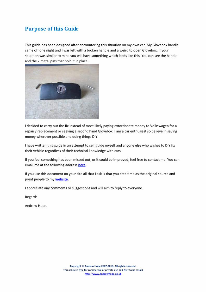
This guide has been designed after encountering this situation on my own car. My Glovebox handle
came off one night and I was left with a broken handle and a weird to open Glovebox. If your
situation was similar to mine you will have something which looks like this. You can see the handle
and the 2 metal pins that hold it in place.
I decided to carry out the fix instead of most likely paying extortionate money to Volkswagen for a
repair / replacement or seeking a second hand Glovebox. I am a car enthusiast so believe in saving
money wherever possible and doing things DIY.
I have written this guide in an attempt to self guide myself and anyone else who wishes to DIY fix
their vehicle regardless of their technical knowledge with cars.
If you feel something has been missed out, or it could be improved, feel free to contact me. You can
email me at the following address here.
If you use this document on your site all that I ask is that you credit me as the original source and
point people to my website.
I appreciate any comments or suggestions and will aim to reply to everyone.
Regards
Andrew Hope.

Copyright © Andrew Hope 2007-2010. All rights reserved.
This article is free for commercial or private use and NOT to be resold
http://www.andrewhope.co.uk
Tools Needed
Torx Screwdriver / Screwdriver & Bit (T20 Sized)
Superglue (Bostik Multi Purpose – Extra Strong Clear)
Duct Tape (for holding the pieces together until glue hardens)
Flat Small Head Screwdriver
Copyright © Andrew Hope 2007-2010. All rights reserved.
This article is free for commercial or private use and NOT to be resold
http://www.andrewhope.co.uk
Repair Procedure
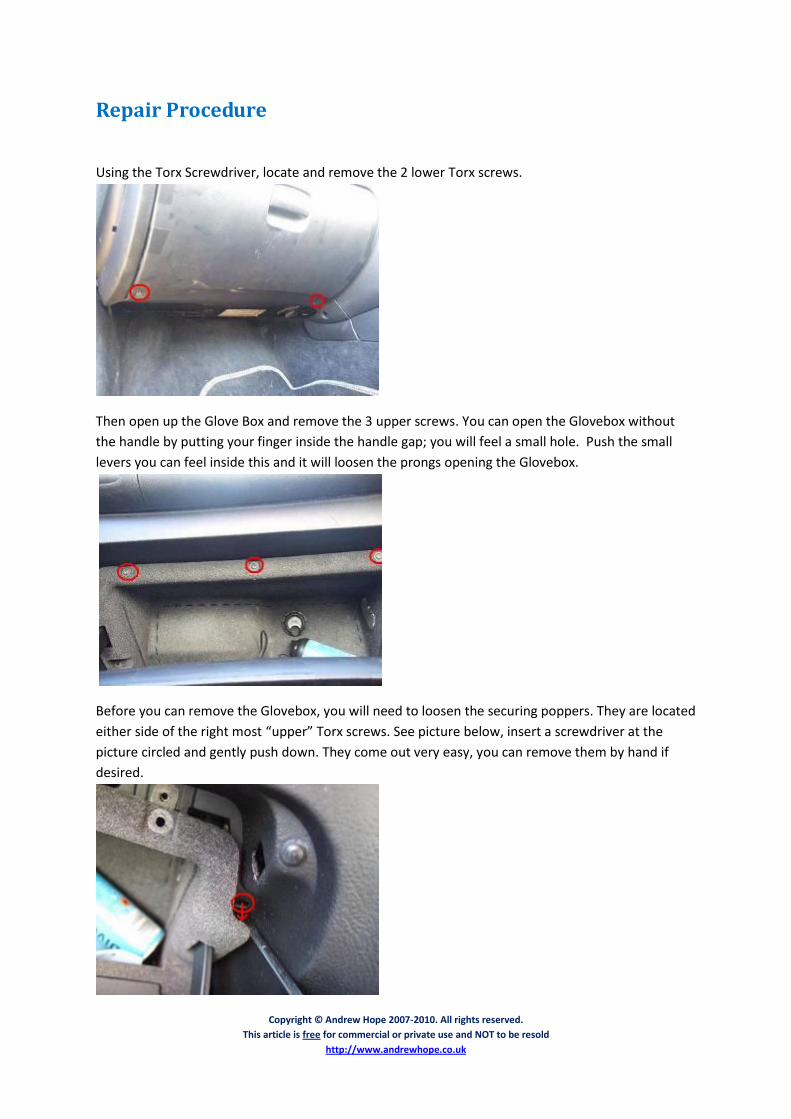
Using the Torx Screwdriver, locate and remove the 2 lower Torx screws.
Then open up the Glove Box and remove the 3 upper screws. You can open the Glovebox without
the handle by putting your finger inside the handle gap; you will feel a small hole. Push the small
levers you can feel inside this and it will loosen the prongs opening the Glovebox.
Before you can remove the Glovebox, you will need to loosen the securing poppers. They are located
either side of the right most “upper” Torx screws. See picture below, insert a screwdriver at the
picture circled and gently push down. They come out very easy, you can remove them by hand if
desired.
Copyright © Andrew Hope 2007-2010. All rights reserved.
This article is free for commercial or private use and NOT to be resold
http://www.andrewhope.co.uk
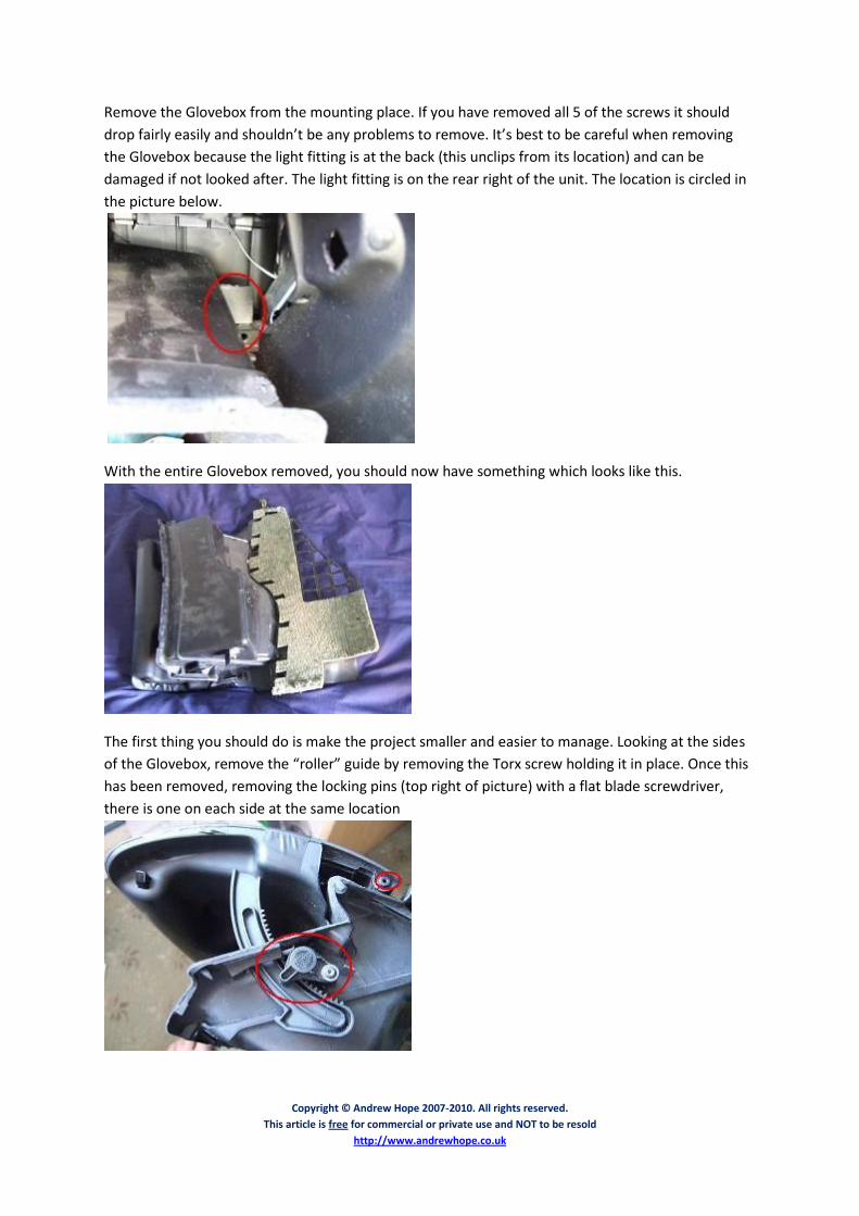
Remove the Glovebox from the mounting place. If you have removed all 5 of the screws it should
drop fairly easily and shouldn’t be any problems to remove. It’s best to be careful when removing
the Glovebox because the light fitting is at the back (this unclips from its location) and can be
damaged if not looked after. The light fitting is on the rear right of the unit. The location is circled in
the picture below.
With the entire Glovebox removed, you should now have something which looks like this.
The first thing you should do is make the project smaller and easier to manage. Looking at the sides
of the Glovebox, remove the “roller” guide by removing the Torx screw holding it in place. Once this
has been removed, removing the locking pins (top right of picture) with a flat blade screwdriver,
there is one on each side at the same location
Copyright © Andrew Hope 2007-2010. All rights reserved.
This article is free for commercial or private use and NOT to be resold
http://www.andrewhope.co.uk
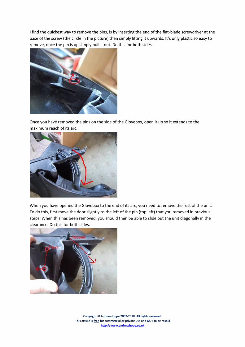
I find the quickest way to remove the pins, is by inserting the end of the flat-blade screwdriver at the
base of the screw (the circle in the picture) then simply lifting it upwards. It’s only plastic so easy to
remove, once the pin is up simply pull it out. Do this for both sides.
Once you have removed the pins on the side of the Glovebox, open it up so it extends to the
maximum reach of its arc.
When you have opened the Glovebox to the end of its arc, you need to remove the rest of the unit.
To do this, first move the door slightly to the left of the pin (top left) that you removed in previous
steps. When this has been removed, you should then be able to slide out the unit diagonally in the
clearance. Do this for both sides.
Copyright © Andrew Hope 2007-2010. All rights reserved.
This article is free for commercial or private use and NOT to be resold
http://www.andrewhope.co.uk
This is what you should now be left with, minus the shield you should merely have the Glovebox lid
itself.
You now need to prise apart the two sections, as this would most likely not have been done before
it’s best to do it gently. Looking at the top of the sections you will see something like this, gently
prise the sections apart and you will see chunks in the plastic missing where it was “bashed” in place.
The parts will eventually come fully apart, don’t worry too much over any sounds as there isn’t really
that much what can be broken inside
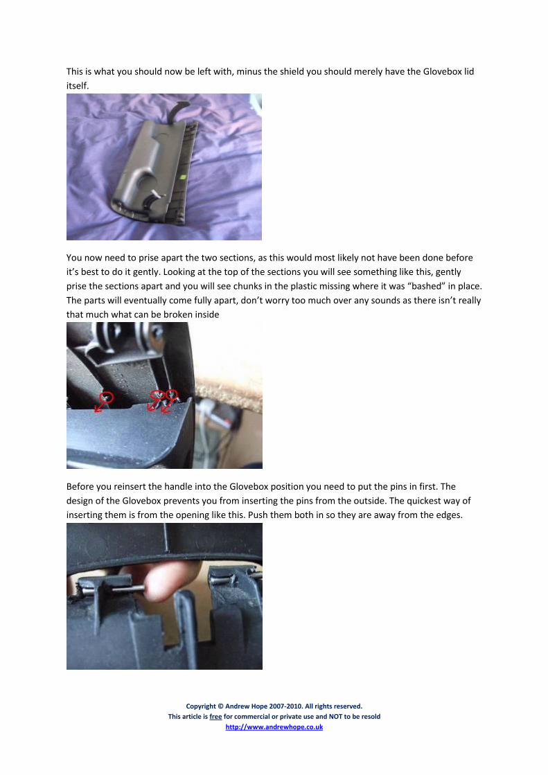
Before you reinsert the handle into the Glovebox position you need to put the pins in first. The
design of the Glovebox prevents you from inserting the pins from the outside. The quickest way of
inserting them is from the opening like this. Push them both in so they are away from the edges.
Copyright © Andrew Hope 2007-2010. All rights reserved.
This article is free for commercial or private use and NOT to be resold
http://www.andrewhope.co.uk
In this picture you can see the alignment of the plastic lock in conjunction with the location of the
plastic where the pins are held. The hole where the pin gets pushed into is circled. The pin gets
pushed into the hole in the direction indicated.
When the lock has been put in place I force the pin into position by using a screwdriver, this allows
you to put a fair amount of pressure on the pin. Once the pin is in place I push it a bit harder to make
sure it stays in position. The arrow indicates the direction to push the pin into the plastic.
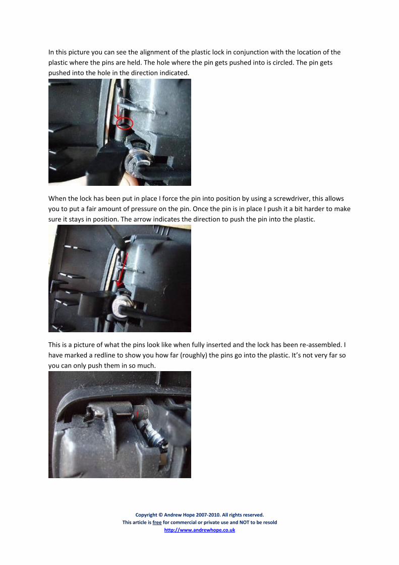
This is a picture of what the pins look like when fully inserted and the lock has been re-assembled. I
have marked a redline to show you how far (roughly) the pins go into the plastic. It’s not very far so
you can only push them in so much.
Copyright © Andrew Hope 2007-2010. All rights reserved.
This article is free for commercial or private use and NOT to be resold
http://www.andrewhope.co.uk
Before reattaching the surfaces, I decided to rough them up a bit to help get the surfaces tacked
together. I used a knife and simply did a few scores on some of the edges where they were attached
like this. It won’t matter if you scratch anywhere on the inside because you simply won’t see it
Before the parts line up you MUST have the handle flat, otherwise they will be hard to join. When
reassembling the two pieces together I decided to give a nice plentiful supply of glue. I merely went
over the plastic areas that had marks indented from the pressure put onto them.
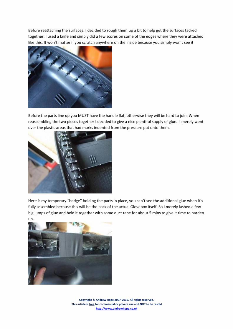
Here is my temporary “bodge” holding the parts in place, you can’t see the additional glue when it’s
fully assembled because this will be the back of the actual Glovebox itself. So I merely lashed a few
big lumps of glue and held it together with some duct tape for about 5 mins to give it time to harden
up.
Copyright © Andrew Hope 2007-2010. All rights reserved.
This article is free for commercial or private use and NOT to be resold
http://www.andrewhope.co.uk
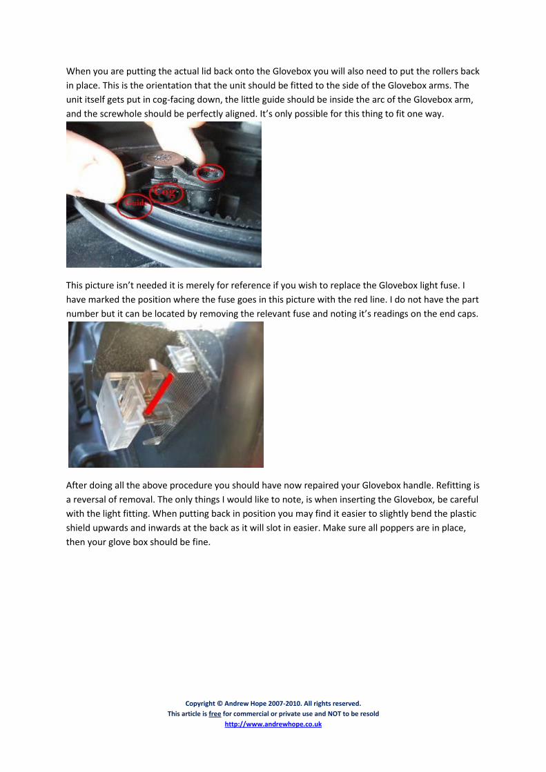
When you are putting the actual lid back onto the Glovebox you will also need to put the rollers back
in place. This is the orientation that the unit should be fitted to the side of the Glovebox arms. The
unit itself gets put in cog-facing down, the little guide should be inside the arc of the Glovebox arm,
and the screwhole should be perfectly aligned. It’s only possible for this thing to fit one way.
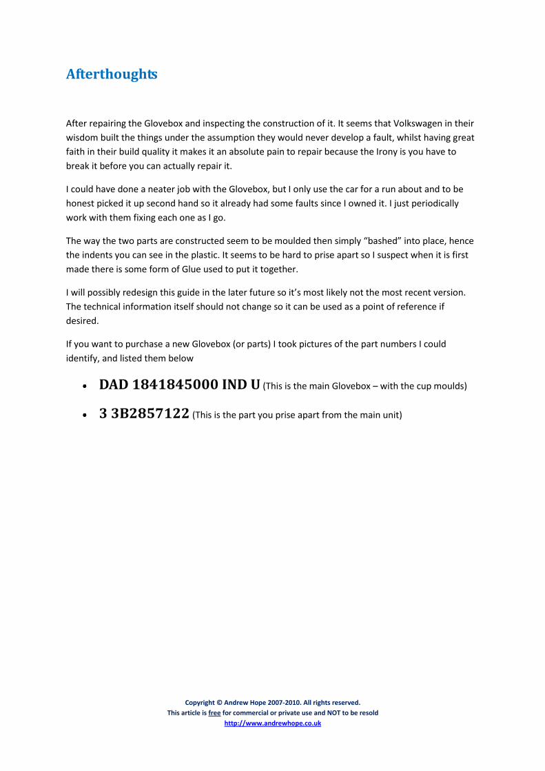
This picture isn’t needed it is merely for reference if you wish to replace the Glovebox light fuse. I
have marked the position where the fuse goes in this picture with the red line. I do not have the part
number but it can be located by removing the relevant fuse and noting it’s readings on the end caps.
After doing all the above procedure you should have now repaired your Glovebox handle. Refitting is
a reversal of removal. The only things I would like to note, is when inserting the Glovebox, be careful
with the light fitting. When putting back in position you may find it easier to slightly bend the plastic
shield upwards and inwards at the back as it will slot in easier. Make sure all poppers are in place,
then your glove box should be fine.
Copyright © Andrew Hope 2007-2010. All rights reserved.
This article is free for commercial or private use and NOT to be resold
http://www.andrewhope.co.uk
Afterthoughts
After repairing the Glovebox and inspecting the construction of it. It seems that Volkswagen in their
wisdom built the things under the assumption they would never develop a fault, whilst having great
faith in their build quality it makes it an absolute pain to repair because the Irony is you have to
break it before you can actually repair it.
I could have done a neater job with the Glovebox, but I only use the car for a run about and to be
honest picked it up second hand so it already had some faults since I owned it. I just periodically
work with them fixing each one as I go.
The way the two parts are constructed seem to be moulded then simply “bashed” into place, hence
the indents you can see in the plastic. It seems to be hard to prise apart so I suspect when it is first
made there is some form of Glue used to put it together.
I will possibly redesign this guide in the later future so it’s most likely not the most recent version.
The technical information itself should not change so it can be used as a point of reference if
desired.
If you want to purchase a new Glovebox (or parts) I took pictures of the part numbers I could
identify, and listed them below
DAD 1841845000 IND U (This is the main Glovebox – with the cup moulds)
3 3B2857122 (This is the part you prise apart from the main unit)

Copyright © Andrew Hope 2007-2010. All rights reserved.
This article is free for commercial or private use and NOT to be resold
http://www.andrewhope.co.uk
The Legal Stuff
Whilst every intent has been taken to ensure the information I provide is fully accurate I urge people
to double check any information I have provided before proceeding.
I am not liable for any faults or damage incurred to your car through reading this guide, you are
under no obligation to seek my assistance for professional advice or to use this guide as a reference
point as such I cannot be held accountable for any faults incurred.