universiti teknikal malaysia melaka -...
TRANSCRIPT
UNIVERSITI TEKNIKAL MALAYSIA MELAKA
PRODUCT DEVELOPMENT OF SEMI AUTOMATIC SLUMP TEST
This report submitted in accordance with requirements of the Universiti Teknikal Malaysia
Melaka (UTeM) for the Bachelor Degree of Manufacturing Engineering (Manufacturing
Design) with Honors.
By
MOHD ZARUL HAZIM BIN NORUDIN
FACULTY OF MANUFACTURING ENGINEERING
2010
UNIVERSITI TEKNIKAL MALAYSIA MELAKA
BORANG PENGESAHAN STATUS LAPORAN PROJEK SARJANA MUDA
TAJUK: PRODUCT DEVELOPMENT SEMI AUTOMATIC SLUMP TEST
SESI PENGAJIAN: 2009/10 Semester 2
Saya MOHD ZARUL HAZIM BIN NORUDIN
mengaku membenarkan Laporan PSM ini disimpan di Perpustakaan UniversitiTeknikal Malaysia Melaka (UTeM) dengan syarat-syarat kegunaan seperti berikut:
1. Laporan PSM adalah hak milik Universiti Teknikal Malaysia Melaka dan penulis.2. Perpustakaan Universiti Teknikal Malaysia Melaka dibenarkan membuat salinan
untuk tujuan pengajian sahaja dengan izin penulis.3. Perpustakaan dibenarkan membuat salinan laporan PSM ini sebagai bahan
pertukaran antara institusi pengajian tinggi.4. **Sila tandakan (√)
SULIT
TERHAD
TIDAK TERHAD
(Mengandungi maklumat yang berdarjah keselamatanatau kepentingan Malaysia yang termaktub di dalam
AKTA RAHSIA RASMI 1972)
(Mengandungi maklumat TERHAD yang telah ditentukanoleh organisasi/badan di mana penyelidikan dijalankan)
Alamat Tetap:
No. 21 Jalan Tilapia 7
Taman Sri Putra
42700,Banting, Selangor
Tarikh: _________________________
Disahkan oleh:
Cop Rasmi:
Tarikh: _______________________
** Jika Laporan PSM ini SULIT atau TERHAD, sila lampirkan surat daripada pihak berkuasa/organisasiberkenaan dengan menyatakan sekali sebab dan tempoh laporan PSM ini perlu dikelaskan sebagai
SULIT atau TERHAD.
20 Mei 2010 20 Mei 2010
DECLARATION
I hereby, declared this report entitled “Product Development Semi Automatic Slump
Test”is the result of my own research except as cited in references.
Signature : … … … … … … … … … … … ........
Author’s name : MOHD ZARUL HAZIM BIN NORUDIN
Date : 9 April 2010
APRPROVAL
This report is submitted to the Faculty of Manufacturing Engineering of UTeM as a
partial fulfillment of the requirements for the degree of Bachelor of Manufacturing
Engineering (Manufacturing Design) with Honors. The member of the supervisory
committee is as follow:
… … … … … … … … … … … … … … … … … .
(Mr. Abdul Halim Hakim Bin Abdul Aziz)
(Official Stamp)
i
ABSTRACT
Concrete slump test (or simply the slump test) is an in situ test or a laboratory test
used to determine and measure how hard and consistent a given sample of concrete is
before curing. The concrete slump test is, in essence, a method of quality control. A
higher slump concrete result means the concrete sample is not stable and a lower
slump concrete result means the concrete is firm. A manual slump test is the
problems that always occur when applying this method test. Inconsistent speed and
lateral vibration while lifting up the cone and human error that cause the cone move
in slight angular direction are the main problem that need to be counter with. This
project presented is to overcome the problems occur in handling the manual concrete
slump test. The aims of the project are to design and produce semi automatic slump
test prototype and to analyst and test the functionality of the lifter. Several designs
of semi automatic slump test were designed and the electrical motor lifter was
selected. The design uses electric motor lifter to move the slump cone in proper
direction as well as overcoming the problems occur in manually done slump test.
This selected design then fabricated and undergo the functionality test. In the end, the
collected data from the functionality test between manual operation and semi
automatic slump test is analyzed with using Pearson correlation. The result carried
out shown that The Semi Automatic Slump Test could replace the manual slump test
due to Pearson Correlation result’s obtained 0.9807 nearly to 1. Semi automatic
Slump equipment is compatible and fits with the slump test value obtained by
standard equipment such as that described in British Standard (BS 1881: Part 102:
1983).
ii
ABSTRAK
Ujian penurunan ialah satu ujian makmal yang digunakan bagi menentukan dan
mengukur kebolehkerjaan sesebuah konkrit. Ujian penurunan konkrit adalah satu
kaedah didalam kawalan mutu didalam industri pembinaan. Keputusan yang
dihasilkan sekiranya keputusan penurunan lebih tinggi beerti sampel konkrit tidak
kukuh dan untuk keputusan konrit yang rendah beerti sampel konkrit adalah kukuh
dan stabil. Semasa ujian penurunan manual ini dilakukan terdapat masalah yang
sering berlaku iaitu dari segi kelajuan yang tidak selaras, gegaran semasa
mengangkat kon dan juga kesilapan manusia apabila memindahkan kon dari konkrit.
Projek ini dihasilkan adalah untuk mengatasi masalah – masalah yang dihadapi
ketika mengendalikan ujian tersebut. Matlamat projek ini adalah untuk mereka
bentuk dan menghasilkan protoip mesin separa automatik bagi ujian ini dan menguji
dan menganalisa fungsi mesin ini .Beberapa rekaan mesin separa automatik telah
dihasilkan dan keputusannya adalah mesin yang menggunakan motor elektrik. Mesin
yang terpilih akan dihasilkan dan diuji prestasinya. Akhirnya,data yang dihasilkan
diantara mesin manual dan separa automatik dianalisis dengan menggunakan kaedah
Pearson Correlation. Hasil yang ditunjukkan adalah mesin separa automatic boleh
menggantikan mesin manual di sebabkan pearson correlation yang diperolehi 0.9807
menghampiri 1. Keputusan analisis ini menunjukkan bahawa mesin separa automatic
adalah sesuai dan serasi bagi menggantikan mesin manual kerana keputusan yang
dihasilkan adalah seperti didalam Standard British(BS 1881: Berpihak 102: 1983).
iii
DEDICATION
For a warmth of love to Abah and Emak, Siblings, friends and my love one.
Thank you for the undivided loves and supports.
iv
ACKNOWLEDGEMENTS
Firstly, the author would like to express his most gratitude to Allah SWT, the most
gracious and merciful for giving his strength to complete this project and thesis,
titled “Product Development of Semi Automatic Slump Test”in Universiti Teknikal
Malaysia Melaka(UTeM) successfully. Author would like to express his deepest
gratitude to his supervisors, Mr. Abdul Halim Hakim bin Abdul Aziz for their
patience, constant guidance and supervision. For without his guides and wisdom this
PSM report would be ruined. Last but not list, not forgotten to thank all FKP
lecturers who had spent their time to teach, explain and answers all the questions.
Author also would like to address very enormous appreciation to his family members
and to his friends for their enthusiastic support in finance, moral, guidance and all
their contributions in order for author to finish this PSM report successfully. Finally,
to those whose names the author had not mentioned, thank you very much for
making this project run smoothly.
v
TABLE OF CONTENT
Declaration
Aproval
Abstract
Abstrak
Dedication
Acknowledgement
Table Of Content
List Of Tables
List Of Figures
List Of Abbreviations
1. INTRODUCTION
1.1 Background
1.2 Problem Statement
1.3 Objectives Of Projects
1.4 Scope And Limitation
1.5 Essential Of The Project
1.6 Project Outline
2. LITERATURE REVIEW
2.1 Introduction
2.2 Concrete
2.2.1 Theory Of Concrete
2.2.2 Concrete And Cement’s History
2.3 Concrete Slump Test
2.3.1 Method Of Slump Test
2.3.2 Working Procedure Of Slump Test
2.4 Lifting Device
2.4.1 Coil Spring
i
ii
iii
iv
v
viii
ix
x
1
1
3
3
3
4
4
5
5
6
7
9
13
14
15
20
21
vi
2.4.2 Electric Motor
2.4.3 Pneumatic Actuator
2.5 Design
2.5.1 Product Design
2.5.2 Design Process
2.6 Decision Matrix
2.6.1 Pugh Concept Selection
2.6.2 Pugh Concept Selection Methodology
2.6.2.1 Step 1: Prepare The Selection Matrix
2.6.2.2 Step 2: Rate The Concepts
2.6.2.3 Step 3: Generate The Score
2.6.2.4 Step 4: Compute The Total Score
2.7 Pearson Correlation
2.7.1 Why The Correlation Takes Values Between −1 And +1?
2.7.2 Interpreting Correlation And Scatter Plots
2.7.3 Linear And Non-Linear Relationship
3. METHODOLOGY
3.1 Introduction
3.2 Planning
3.3 Process Flow Chart
3.4 Study And Research
3.4.1 Manual Slump Test Identification
3.5 Design Generation
3.6 CAD Drawing
3.7 Analysis
3.7.1 Functionality Analysis
3.7.1.1 The Formula For The Pearson Correlation
4. RESULT AND DISCUSSION
4.1 Design Selection
4.2 Motor Slump Cone Lifter
22
23
25
25
26
28
29
30
30
31
32
32
32
34
35
35
36
36
36
37
38
38
38
38
42
42
42
43
43
45
vii
4.2.1 Tool Of Semi Automatic Slump Test Apparatus
4.3 Functionality Test Of Semi Automatic Slump Test
4.3.1 Standard Operation Procedures (SOP) for the functionality test
4.4 Result
4.4.1 type of slump condition
4.5 Data Analysis
5. CONCLUSION AND RECOMMENDATION
REFERENCES
APPENDIX A
APPENDIX B
46
48
49
52
53
57
61
viii
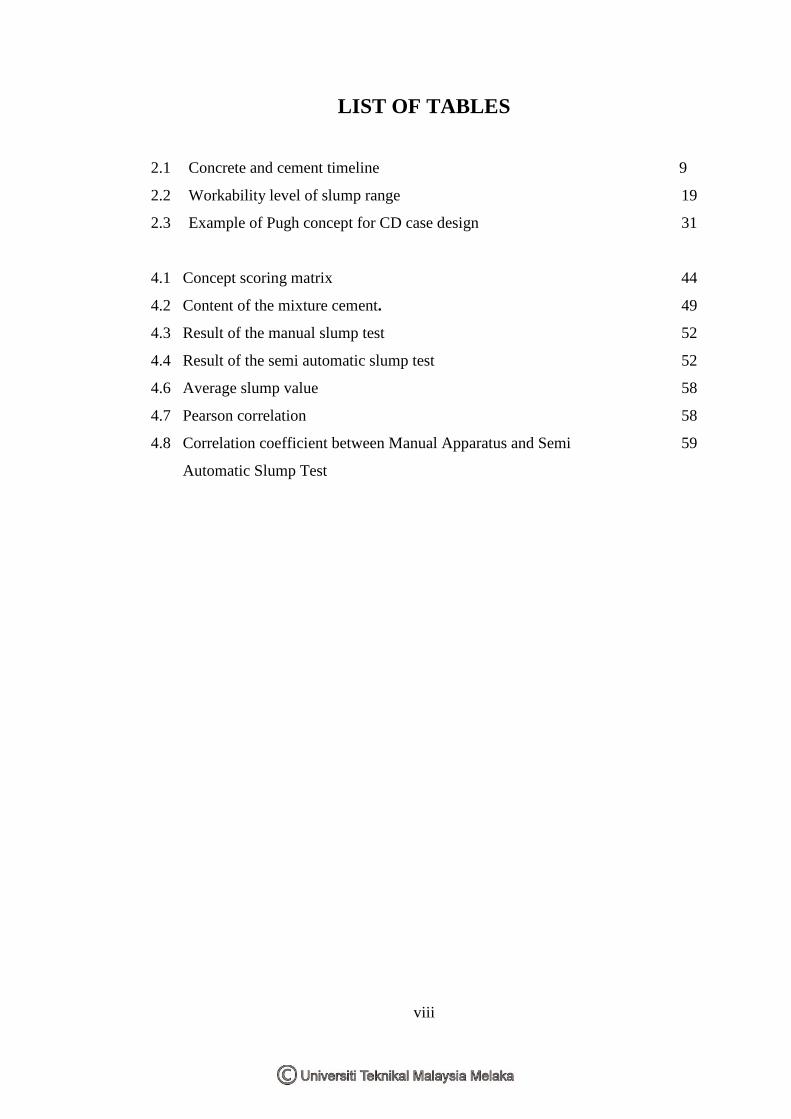
LIST OF TABLES
2.1 Concrete and cement timeline
2.2 Workability level of slump range
2.3 Example of Pugh concept for CD case design
4.1 Concept scoring matrix
4.2 Content of the mixture cement.
4.3 Result of the manual slump test
4.4 Result of the semi automatic slump test
4.6 Average slump value
4.7 Pearson correlation
4.8 Correlation coefficient between Manual Apparatus and Semi
Automatic Slump Test
9
19
31
44
49
52
52
58
58
59
xi
LIST OF FIGURES
2.1 Apparatus set for slump test
2.2 Pie chart of ingredient in concrete
2.3 Slump Cone
2.4 Concrete slump test
2.5 Measuring a slump test
2.6 Three form of slump
2.7 Slump test tools and equipments
2.8 First stage of compacting concrete sample
2.9 Second stage of compacting concrete sample
2.10 Third stage of compacting concrete sample
2.11 The overflows sample were leveled
2.12 The cone were carefully lifted up
2.13 Rod act as a level to measure the slump
2.14 Several measurement made to get the average result
2.15 Common slump test result
2.16 Compression coil spring
2.17 The three-phase AC induction motors
2.18 Single acting cylinder with spring return
2.19 Double acting cylinder
2.20 The optimization nail clipper on the right figure from the
original nail clipper on the left figure
2.21 Engineering design process
2.22 Example of relationship between two variables (A) positive
linear relationship (B) negative linear relationship (C) no linear
relationship
3.1 Process flow chart
3.2 Isometric view of spring slump cone lifter
3.3 Isometric view of electric motor slump cone lifter
3.4 Isometric view of pneumatic slump cone lifter
6
7
13
13
14
15
16
16
17
17
18
18
19
19
20
22
23
24
25
26
27
35
37
39
40
41
xii
4.1 Semi automatic slump test
4.2 Body frame
4.3 Magnetic sensor system
4.4 The cone
4.5 top view semi automatic slump test
4.6 Cleaned the slump plate.
4.7 Filled with the concrete
4.8 Leveled the top surface.
4.9 Plate of the cone were cleaned
4.10 Open the lock
4.11 Cone will pull up automatically
4.12 True condition
4.13 Shear condition
4.14 Collapse condition.
4.15 Comparison graph between manual apparatus and
semi automatic
45
46
47
47
48
49
50
50
51
51
51
53
55
55
60
x
LIST OF ABBREVIATIONS
CAD Computer Aided Drawing
CAM Computer Aided Machine
USA United State America
BS British Standart
AC Alternating Current
DC Direct Current
3D Three Dimension
ASTM American Society for Testing and Materials
Mm millimeter
Avg average
1
CHAPTER 1
INTRODUCTION
1.1 Background
"Working with my dad for a few years and associating myself with people who are
passionate about concrete and making concrete better, I find that it is quite
amazing," says Chris Yong, one of the most successful concrete entrepreneur in
Brunei. In this world of technology, buildings and houses grow rapidly to overcome
wants and needs of human being. Humans are eager to grip the profit here and there
to compete with others. Malaysian populations that increase drastically from time to
time in certain advance city requires place of living and other essentials which comes
in construction and architectures such as buildings, highways, streets, parking lots,
parking garages, bridges, high-rise buildings, dams, homes, floors, sidewalks,
driveways, roads and numerous other applications.
Concrete’s versatility, durability, and economy have made it the world’s most used
construction material. It is a constructional material composed of cement, water,
coarse and fine aggregates materials, and admixtures (if required). A properly
proportioned concrete mix possesses acceptable workability of the freshly mixed
concrete and durability, strength, and uniform appearance of the hardened concrete
while being economical. Basically, concrete is a mixture of two components:
aggregates and paste. The paste, comprised of cement and water, binds the
aggregates (usually sand and gravel or crushed stone) into a rocklike mass as the
paste hardens because of the chemical reaction of the cement and water.
Supplementary cementations materials and chemical admixtures may also be
included in the paste.
2
Concrete slump test (or simply the slump test) is an in situ test or a laboratory test
used to determine and measure how hard and consistent a given sample of concrete is
before curing. The concrete slump test is, in essence, a method of quality control.
"Slump" is simply a term coined to describe how consistent a concrete sample is,
rather than using obscure descriptions such as "wet" or "runny". The height of the
concrete mix after being placed in the slump cone differs from one sample to
another. Samples with lower heights are predominantly used in construction, with
samples having high slumps commonly used to construct roadway pavements. For a
particular mix, the slump should be consistent.
A change in slump height would demonstrate an undesired change in the ratio of the
concrete ingredients; the proportions of the ingredients are then adjusted to keep a
concrete batch consistent. This homogeneity improves the quality and structural
integrity of the cured concrete. Those concrete conditions were taken into account
when satisfying requirements of concrete strength, and to make sure that a consistent
mixture of cement is being used during the process of construction.
The manual slump test has several problems in processing the method. Using the
manual slump test, operator will be using the man power to lift up the slump cone.
This condition will lead to inconsistency in speed and a slight angular upwards
direction resulting unreliable measurement result data. Thus, this study main
objective is to design and produce semi automatic slump test that can provide
consistent speed when lifting the slump cone and further it can overcome the
problems occurs when manually operate concrete slump test. According to the topic,
project development is explaining on the semi-auto slump test. Hence, automatic are
behalf of running testing with mechanism either motto, spring or pneumatic while
semi is means power to insert cement in the cone using roding that conducted by
man’s power.
3
1.2 Problems Statements
Concrete is quite literally the foundation of many of today's construction projects. It
is also widely used for exterior surfaces driveways, sidewalks, patios, stoops, steps,
and another else. No wonder the Concrete is strong, durable, and relatively
inexpensive and can be formed into many shapes and sizes. But concrete also has its
drawbacks. It's prone to crumbling, cracking, settling and heaving when exposed to
the elements. It also stains rather easily. Commonly, the slump test is operated
manually by operator.
In manually done slump test, there are several problems that occur when operating
this measurement method. These situations affect the results of the slump test
unreliable because:
a. The resulting concrete was collapses or shear to one side.
b. Data from the slump test result need to be measure several times.
These entire problems have been researched to understand the reason of these
problems. Thus basically these entire problems happen due to:
a. Inconsistent speed when lifting the slump cone.
b. Human error that cause the lifting process move in slight angular direction.
c. Lateral and torsion vibration of the slump cone during lifting process.
1.3 Objectives Of Projects
a. To design and produce semi automatic slump test prototype.
b. To Analyze and test the functionality of the lifter.
1.4 Scope and Limitation
a. To study the existing product performance.
b. To compare result between manual slump test and semi automatic slump test
4
c. To verify and analyzed the data using Pearson correlation method.
d. The design of semi automatic slump test with using the CAD software and
illustrate it in technical drawing.
1.5 Essential of the Project
The essential of this project is:
a. To apply the product design and development concept that related to the
subject.
b. Propose a design concept of slump cone lifter that has a consistent speed
when lifting the cone upwards, reduce the slight angular upward direction and
reduce the lateral and torsion vibration during the lifting process.
c. As a reference for academic studies that related to an automatic slump cone
lifter.
1.6 Project Outline
This PSM report will contain six chapter which is chapter 1 that contains the
introduction of the PSM project, Product Development Semi Automatic Slump Test
where include objectives, problem statement and also some of the important
information about the background of the project. Chapter 2 contains the literature
review of the existing slump cone and others topic that related in this PSM project.
Chapter 3 will represent the methodology of the PSM project from research until the
development of the project. Chapter 4 will represent the result and discussion from
the analysis taken using the functionality test. Chapter 5 contents the conclusion and
recommendation of this entire report.
5
CHAPTER 2
LITERATURE REVIEW
2.1 Introduction
The slump test is the simplest and most commonly used test for workability. This
chapter will describe about all element that are considered assisting and method used
by authors in understanding and completing the project of design and development of
semi automatic slump test. Literature reviews is a research or study that taken from
primary and secondary data collection. Primary data is an investigation or direct
search taken from discussion, site visit and interview with an expert of this field. The
secondary data is a data from printed document such as books, journal, and recent
design and also internet.
In process to do the research, investigation and design of a new product, literature
review is an important guidance to support the acts and process of a research. The
title of study, research, and applied method will be explain in sequence of authors
comprehension from the concrete slump test application, working procedure, and
function of the test until the design consideration and evaluation of semi automatic
slump test using the Pugh concept selection matrix. The apparatus set for slump test
as shown in figure 2.1
6
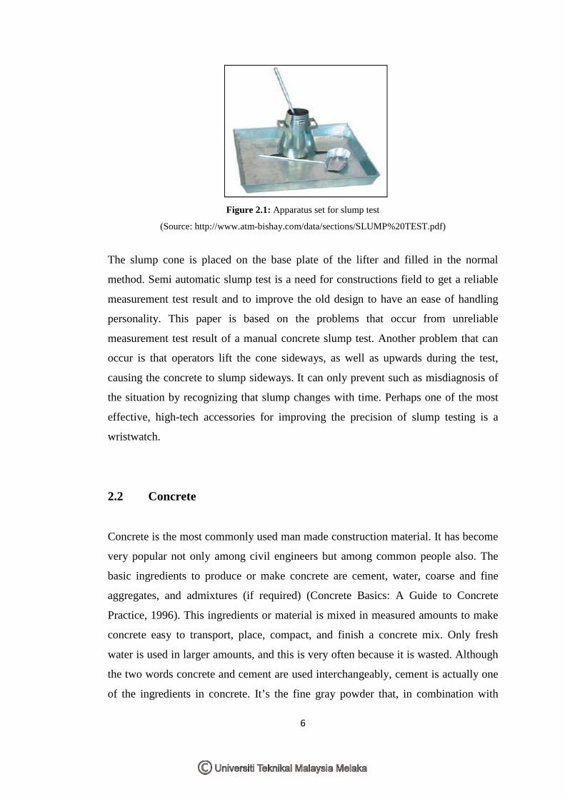
Figure 2.1: Apparatus set for slump test
(Source: http://www.atm-bishay.com/data/sections/SLUMP%20TEST.pdf)
The slump cone is placed on the base plate of the lifter and filled in the normal
method. Semi automatic slump test is a need for constructions field to get a reliable
measurement test result and to improve the old design to have an ease of handling
personality. This paper is based on the problems that occur from unreliable
measurement test result of a manual concrete slump test. Another problem that can
occur is that operators lift the cone sideways, as well as upwards during the test,
causing the concrete to slump sideways. It can only prevent such as misdiagnosis of
the situation by recognizing that slump changes with time. Perhaps one of the most
effective, high-tech accessories for improving the precision of slump testing is a
wristwatch.
2.2 Concrete
Concrete is the most commonly used man made construction material. It has become
very popular not only among civil engineers but among common people also. The
basic ingredients to produce or make concrete are cement, water, coarse and fine
aggregates, and admixtures (if required) (Concrete Basics: A Guide to Concrete
Practice, 1996). This ingredients or material is mixed in measured amounts to make
concrete easy to transport, place, compact, and finish a concrete mix. Only fresh
water is used in larger amounts, and this is very often because it is wasted. Although
the two words concrete and cement are used interchangeably, cement is actually one
of the ingredients in concrete. It’s the fine gray powder that, in combination with
7
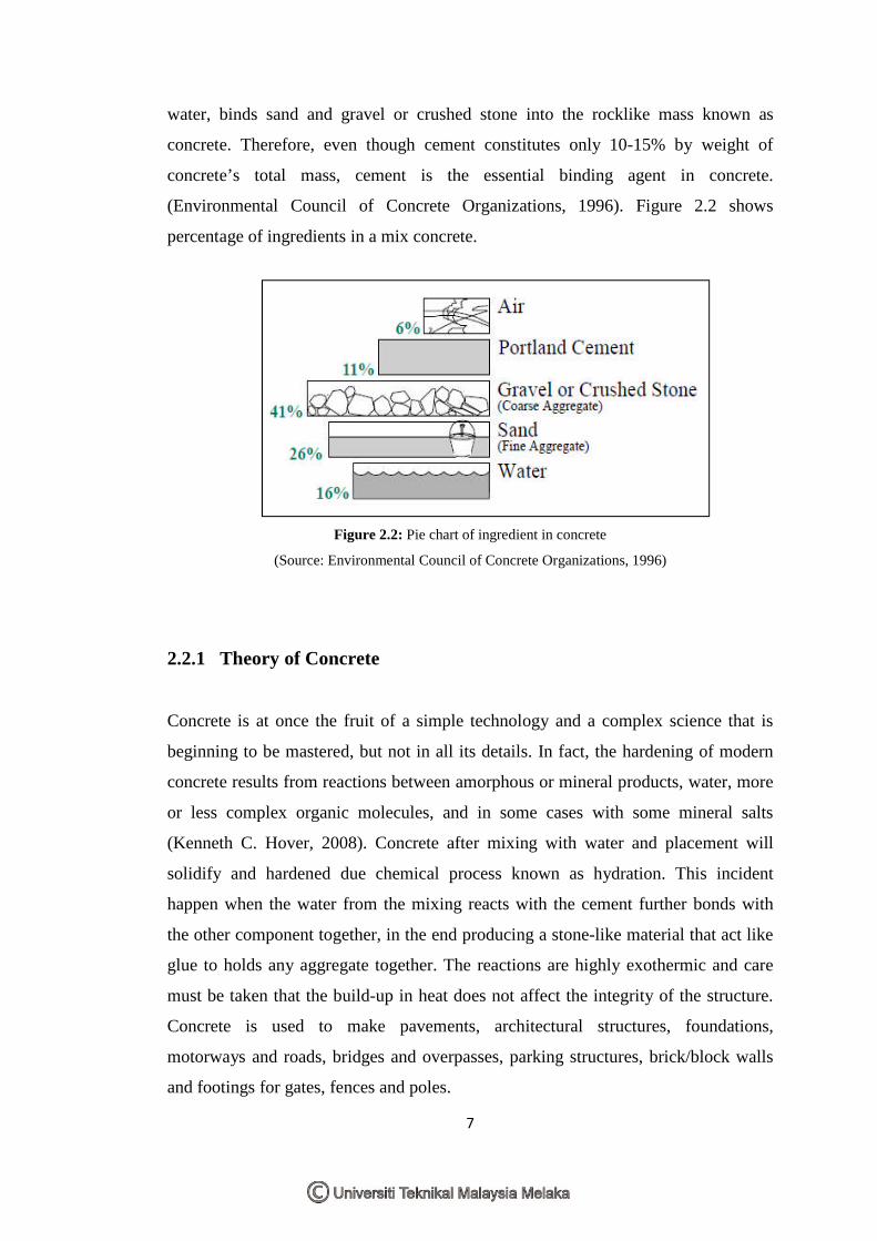
water, binds sand and gravel or crushed stone into the rocklike mass known as
concrete. Therefore, even though cement constitutes only 10-15% by weight of
concrete’s total mass, cement is the essential binding agent in concrete.
(Environmental Council of Concrete Organizations, 1996). Figure 2.2 shows
percentage of ingredients in a mix concrete.
Figure 2.2: Pie chart of ingredient in concrete
(Source: Environmental Council of Concrete Organizations, 1996)
2.2.1 Theory of Concrete
Concrete is at once the fruit of a simple technology and a complex science that is
beginning to be mastered, but not in all its details. In fact, the hardening of modern
concrete results from reactions between amorphous or mineral products, water, more
or less complex organic molecules, and in some cases with some mineral salts
(Kenneth C. Hover, 2008). Concrete after mixing with water and placement will
solidify and hardened due chemical process known as hydration. This incident
happen when the water from the mixing reacts with the cement further bonds with
the other component together, in the end producing a stone-like material that act like
glue to holds any aggregate together. The reactions are highly exothermic and care
must be taken that the build-up in heat does not affect the integrity of the structure.
Concrete is used to make pavements, architectural structures, foundations,
motorways and roads, bridges and overpasses, parking structures, brick/block walls
and footings for gates, fences and poles.
8
Three different states to mixed concrete:
a. Plastic state: is when the concrete first mixed, when it is still soft and still can
be worked or molded into any shapes. During this state, the concrete is best to
placing and compaction to any desired place and shape.
b. Setting state: this state takes place after compaction and during finishing.
After that the setting state concrete begins to gain strength and harden.
c. Hardening state: this cannot be place or molded to other place or shape.
There are four main properties of mixed concrete which is:
a. Workability
b. Cohesiveness
c. Strength
d. durability
Workability of a concrete affected b the amount of cement paste and the aggregate
grading inside the concrete mixed. A well made concrete is naturally strong and
durable material. It is necessary to be sure that this concrete will keep its mechanical
strength during the whole life of the structure. It is dense, reasonably watertight, able
to resist changes in temperature, and as well as wear and tear from weathering. If the
concrete is not constructed properly, it will not be as strong or durable when finally
hardened.
A measurement method to check concrete workability will be discussed in the next
sub topic. Cohesiveness properties are how well the concrete holds together in plastic
state. This property was affected by the aggregate grading and the water content of
the mixed concrete. The strength and durability properties of concrete were affected
by the compaction of the concrete. Although concrete compressive strength is not its
essential characteristic because it is its durability that it is more important, it must be
admitted that these two characteristics are intimately linked to one another.
Compaction is removing the air within concrete. A proper compaction results the
concrete with increasing the density which is stronger and more durable.
9
2.2.2 Concrete and Cement’s History
Concrete is a manmade building material that looks like stone. Combining cement
with aggregate and sufficient water makes concrete. Water allows it to set and bind
the materials together. Different mixtures are added to meet specific requirements.
Concrete is normally reinforced with the use of rods or steel mesh before it is poured
into moulds. Interestingly, the history of concrete finds evidence in Rome some 2000
years back. Concrete was essentially used in aqueducts and roadway construction in
Rome. Cement and concrete will remain, at least during the first half of the 21st
century the most widely used construction materials in the world, although this future
concrete could be quite different from that used today. (Pierre-Claude, 2000)
It is said that the Romans used a primal mix for their concrete. It consisted of small
gravel and coarse sand mixed with hot lime and water, and sometimes even animal
blood. To trim down shrinkage, they are known to have used horsehair. Historical
evidence states that the Assyrians and Babylonians used clay as the bonding material.
Even ancient Egyptians are believed to have used lime and gypsum cement for
concrete. Lime mortars and gypsums were also used in building the world-acclaimed
pyramids.
However, Romans are known to have made wide usage of concrete for building
roads. It is interesting to learn that they built some 5,300 miles of roads using
concrete. Concrete is a very strong building material. Historical evidence also points
that Romans used Pozzalana, animal fat, milk and blood as admixtures for building
concrete (http://nabataea.net/cement.html)
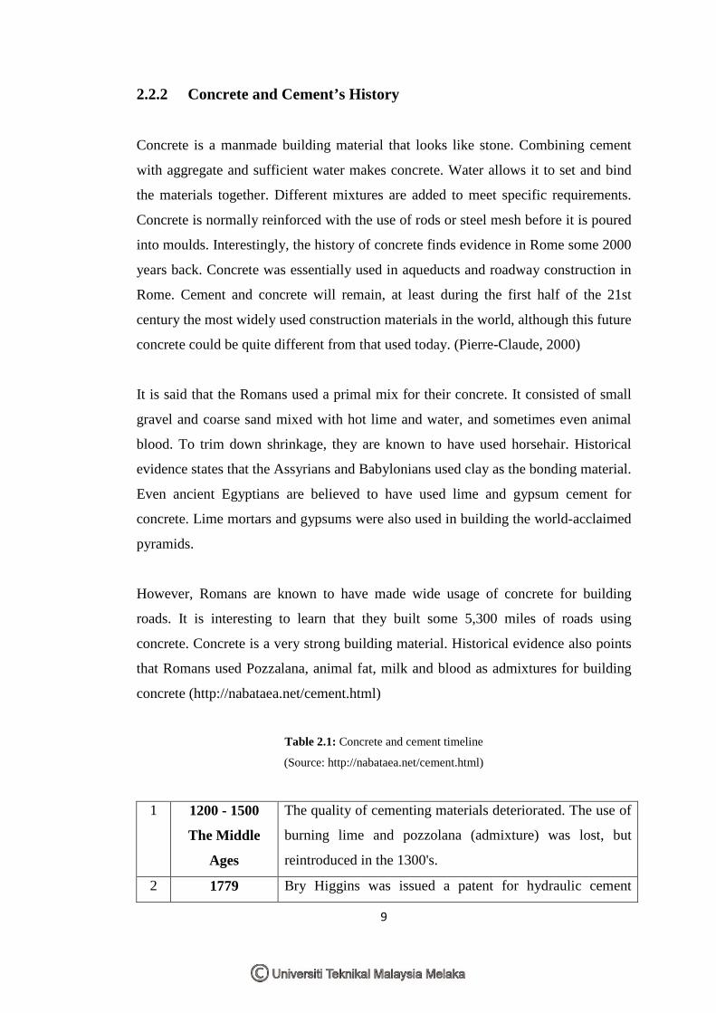
Table 2.1: Concrete and cement timeline
(Source: http://nabataea.net/cement.html)
1 1200 - 1500
The Middle
Ages
The quality of cementing materials deteriorated. The use of
burning lime and pozzolana (admixture) was lost, but
reintroduced in the 1300's.
2 1779 Bry Higgins was issued a patent for hydraulic cement