turned windrow composting - vermontdec.vermont.gov/sites/dec/files/wmp/solidwaste/documents/anr...
TRANSCRIPT
1Sizing Your Composting Pad
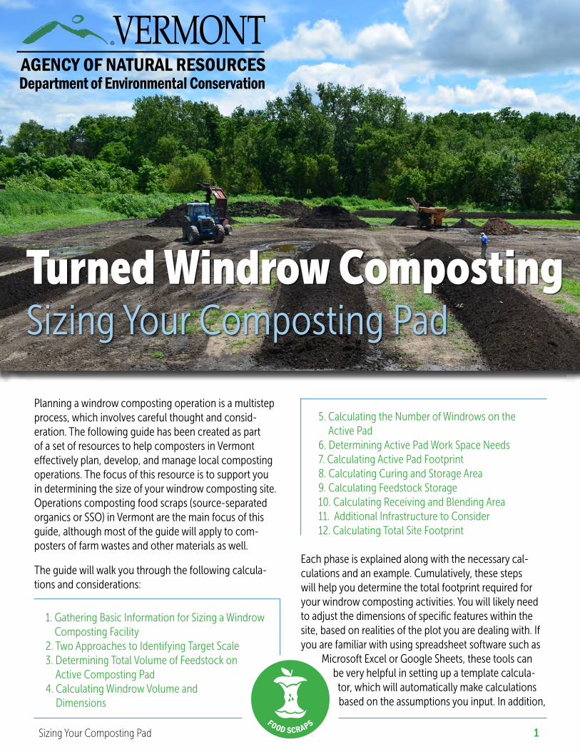
Turned Windrow CompostingSizing Your Composting Pad
Planning a windrow composting operation is a multistep process, which involves careful thought and consid-eration. The following guide has been created as part of a set of resources to help composters in Vermont effectively plan, develop, and manage local composting operations. The focus of this resource is to support you in determining the size of your windrow composting site. Operations composting food scraps (source-separated organics or SSO) in Vermont are the main focus of this guide, although most of the guide will apply to com-posters of farm wastes and other materials as well.
The guide will walk you through the following calcula-tions and considerations:
1. Gathering Basic Information for Sizing a Windrow Composting Facility
2. Two Approaches to Identifying Target Scale 3. Determining Total Volume of Feedstock on
Active Composting Pad4. Calculating Windrow Volume and
Dimensions
5. Calculating the Number of Windrows on the Active Pad
6. Determining Active Pad Work Space Needs7. Calculating Active Pad Footprint8. Calculating Curing and Storage Area9. Calculating Feedstock Storage10. Calculating Receiving and Blending Area11. Additional Infrastructure to Consider12. Calculating Total Site Footprint
Each phase is explained along with the necessary cal-culations and an example. Cumulatively, these steps will help you determine the total footprint required for your windrow composting activities. You will likely need to adjust the dimensions of specific features within the site, based on realities of the plot you are dealing with. If you are familiar with using spreadsheet software such as
Microsoft Excel or Google Sheets, these tools can be very helpful in setting up a template calcula-
tor, which will automatically make calculations based on the assumptions you input. In addition,
2Sizing Your Composting Pad
you may find it helpful to draw your design concept as you work, particularly if you already have a site in mind, but also just to help you to visualize the spatial relation-ships represented by the calculations. Working with a conceptual site layout as you go through the steps and calculations can ultimately make for a stronger and more efficient design process.
Notes on applicability of this guide:
a) The math in this guide is specific to designing rectangular sites; additional steps will be required to assess the processing capacity of non-rectangular locations
b) The math in this guide is specific to sizing the compost management, curing, and storage areas of turned wind-row composting operations; does not address the sizing of infrastructure for other composting methods or of storm or wastewater management systems.Table of Contents
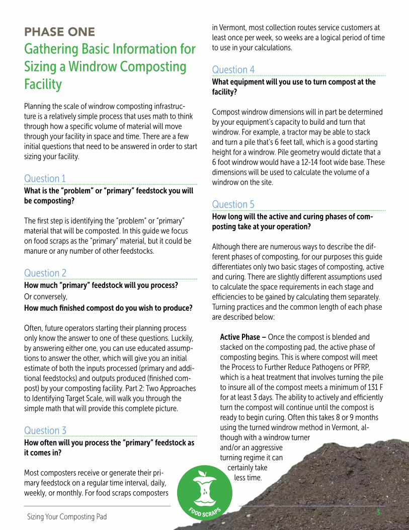
By far the most common technique for composting beyond home scale is the turned windrow meth-od. A windrow is an elongated pile, which is generally turned or “rolled” from the side with a bucket loader, tractor, or a specially engineered machine called a windrow turner. Windrows can also be turned by hand by volunteers in human powered operations. The long shape of a windrow makes the piles easy to turn and provides surface area for passive airflow into the compost. Windrows also provide a sim-ple means to organize a compost site, by combining and tracking materials of a similar age in a scalable volume.
From Growing Local Fertility: A Guide to Community Composting
Gathering Basic Information for Sizing a Windrow Composting Facility ........................................... 3Two Approaches to Identifying Target Scale ............................................................................................. 5
1. Primary Feedstock Approach ..............................................................................................................................5
2. Target Output Approach .......................................................................................................................................6Determining Total Volume of Feedstock on Active Composting Pad ................................................ 7Calculating Windrow Volume and Dimensions ........................................................................................ 7Calculating Number of Windrows on the Active Pad .............................................................................. 8Determining Active Pad Workspace Needs ................................................................................................ 8Calculating Active Pad Footprint .................................................................................................................. 9Calculating Curing and Storage Area .......................................................................................................... 10Calculating Feedstocks Storage .................................................................................................................... 12Calculating Receiving and Blending Area .................................................................................................. 13Additional Infrastructure to Consider .......................................................................................................... 14Calculating Total Site Footprint .................................................................................................................... 14References .......................................................................................................................................................... 16
Companion Resource:
Turned Windrow Composting: Site Identification & Design Considerations
3Sizing Your Composting Pad
Planning the scale of windrow composting infrastruc-ture is a relatively simple process that uses math to think through how a specific volume of material will move through your facility in space and time. There are a few initial questions that need to be answered in order to start sizing your facility.
Question 1What is the “problem” or “primary” feedstock you will be composting?
The first step is identifying the “problem” or “primary” material that will be composted. In this guide we focus on food scraps as the “primary” material, but it could be manure or any number of other feedstocks.
Question 2How much “primary” feedstock will you process? Or conversely,How much finished compost do you wish to produce?
Often, future operators starting their planning process only know the answer to one of these questions. Luckily, by answering either one, you can use educated assump-tions to answer the other, which will give you an initial estimate of both the inputs processed (primary and addi-tional feedstocks) and outputs produced (finished com-post) by your composting facility. Part 2: Two Approaches to Identifying Target Scale, will walk you through the simple math that will provide this complete picture.
Question 3How often will you process the “primary” feedstock as it comes in?
Most composters receive or generate their pri-mary feedstock on a regular time interval, daily, weekly, or monthly. For food scraps composters
in Vermont, most collection routes service customers at least once per week, so weeks are a logical period of time to use in your calculations.
Question 4What equipment will you use to turn compost at the facility?
Compost windrow dimensions will in part be determined by your equipment’s capacity to build and turn that windrow. For example, a tractor may be able to stack and turn a pile that’s 6 feet tall, which is a good starting height for a windrow. Pile geometry would dictate that a 6 foot windrow would have a 12-14 foot wide base. These dimensions will be used to calculate the volume of a windrow on the site.
Question 5How long will the active and curing phases of com-posting take at your operation?
Although there are numerous ways to describe the dif-ferent phases of composting, for our purposes this guide differentiates only two basic stages of composting, active and curing. There are slightly different assumptions used to calculate the space requirements in each stage and efficiencies to be gained by calculating them separately. Turning practices and the common length of each phase are described below:
Active Phase – Once the compost is blended and stacked on the composting pad, the active phase of composting begins. This is where compost will meet the Process to Further Reduce Pathogens or PFRP, which is a heat treatment that involves turning the pile to insure all of the compost meets a minimum of 131 F for at least 3 days. The ability to actively and efficiently turn the compost will continue until the compost is ready to begin curing. Often this takes 8 or 9 months using the turned windrow method in Vermont, al-though with a windrow turner and/or an aggressive turning regime it can
certainly take less time.
PHASE ONEGathering Basic Information for Sizing a Windrow Composting Facility
∞ Food scrap composter ∞ Processing 10 tons/week or ~20 yards3/week food
scraps∞ Uses a ratio of 4 parts additional feedstocks to 1 part
food scraps∞ Active composting phase of 8 months∞ Curing composting phase of 2 months∞ Needs to store compost for ≤6 months∞ Tractor turned windrows - can stack and turn a pile
up to 6 feet tall∞ Volume of raw compost will shrink by 20% at time of
blending∞ Volume of raw compost will shrink by an additional
40% during active composting and curing or a total of 60%
∞ The site has 25 foot work alleys between the active windrows
∞ The site has a 10 foot perimeter on three sides of the active pad (the forth side has a 25 foot work alley).
∞ The site does not have any additional travel
lanes running per-pendicular to the windrows.
4Sizing Your Composting Pad
Curing Phase – After the active phase of composting, most composters finish their compost by “curing” it. In general, curing compost can remain aerobic with only passive oxygen supplied by convection, as long as the compost is adequately porous and the windrows are relatively small. For this reason, piles can be stacked side by side, without work lanes in between them, which conserves space. Assuming the active phase of composting was successful, curing of compost usu-ally takes between 1 and 3 months (although it can be stored indefinitely). A good rule of thumb is that the curing process starts when the temperature of the compost is between 90 and 100 F.
Estimating the duration of the composting process conservatively is recommended, which means planning for the maximum amount of time you think the process may take. Under sizing facilities is a very common mistake that can have real impacts on an operation’s efficiency, flexibility, and long-term growth.
Question 6How long will you need to store compost at your operation?
Compost that has met your “curing criteria” can be used or sold immediately, but most compost will leave the facility in spring or fall (and late winter for some bagged products). Most composters have a need to store signifi-cant volumes of finished compost for many months at a time between sales seasons. For example compost that is cured in late October may not be sold until April of the following year, so that batch will need to be stored for 5-6 months. More compost will continue to finish curing over that time, so effectively, the facility needs storage for 5-6 months of finished compost outputs.
Planning the space requirements for storing finished compost is different than for active or curing compost, although this guide combines curing and storage for sizing purposes (because it doesn’t necessarily make sense to move a cured pile to a separate storage area, unless other factors deem it necessary). Finished com-post can be stored in much larger piles than active or curing compost, so if you have the capacity to stack taller piles without driving on them, you can plan for taller average pile height in the
curing and storage area. At this late stage of the com-posting process, oxygen demand is minimal, and large piles can maintain quality, even when stacked >8 feet tall. Worth noting, in Vermont, finished compost can be stored outside of the permitted compost management area.
In addition to these initial questions, other questions will be explained as they come up throughout this guide.
Steps 1-37 provide a relatively simple algorithm where you may use the assump-tions specific to your operation to estimate your facility’s required footprint. The exam-ples given along with each step are based on a composting scenario with the follow-ing assumptions:
5Sizing Your Composting Pad
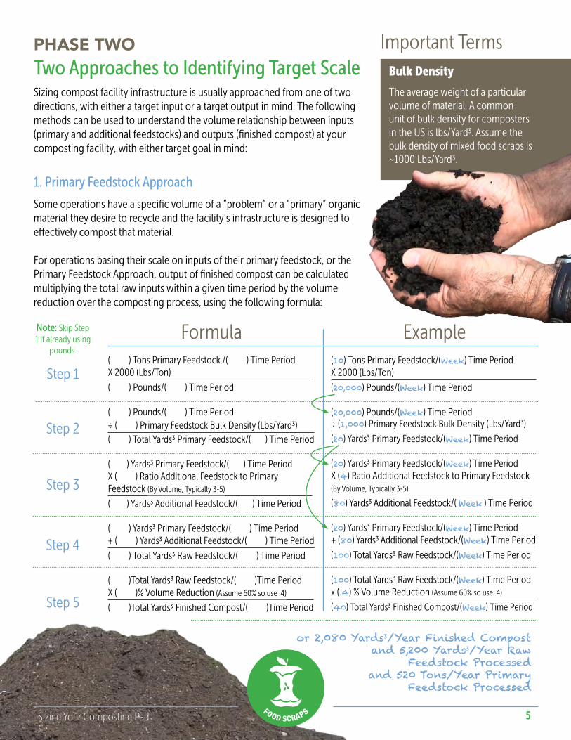
Two Approaches to Identifying Target ScaleSizing compost facility infrastructure is usually approached from one of two directions, with either a target input or a target output in mind. The following methods can be used to understand the volume relationship between inputs (primary and additional feedstocks) and outputs (finished compost) at your composting facility, with either target goal in mind:
Formula Example
PHASE TWO Important Terms
The average weight of a particular volume of material. A common unit of bulk density for composters in the US is lbs/Yard3. Assume the bulk density of mixed food scraps is ~1000 Lbs/Yard3.
Bulk Density
1. Primary Feedstock Approach
Some operations have a specific volume of a “problem” or a “primary” organic material they desire to recycle and the facility’s infrastructure is designed to effectively compost that material.
For operations basing their scale on inputs of their primary feedstock, or the Primary Feedstock Approach, output of finished compost can be calculated multiplying the total raw inputs within a given time period by the volume reduction over the composting process, using the following formula:
( ) Tons Primary Feedstock /( ) Time Period X 2000 (Lbs/Ton)
( ) Pounds/( ) Time Period
( ) Pounds/( ) Time Period÷ ( ) Primary Feedstock Bulk Density (Lbs/Yard3) ( ) Total Yards3 Primary Feedstock/( ) Time Period
( ) Yards3 Primary Feedstock/( ) Time PeriodX ( ) Ratio Additional Feedstock to PrimaryFeedstock (By Volume, Typically 3-5)
( ) Yards3 Additional Feedstock/( ) Time Period
( ) Yards3 Primary Feedstock/( ) Time Period + ( ) Yards3 Additional Feedstock/( ) Time Period
( ) Total Yards3 Raw Feedstock/( ) Time Period
( )Total Yards3 Raw Feedstock/( )Time PeriodX ( )% Volume Reduction (Assume 60% so use .4)
( )Total Yards3 Finished Compost/( )Time Period
Step 1
Step 2
Note: Skip Step 1 if already using
pounds.
Step 5
Step 4
Step 3
(10) Tons Primary Feedstock/(Week) Time Period X 2000 (Lbs/Ton)
(20,000) Pounds/(Week) Time Period
(20,000) Pounds/(Week) Time Period÷ (1,000) Primary Feedstock Bulk Density (Lbs/Yard3)
(20) Yards3 Primary Feedstock/(Week) Time Period
(20) Yards3 Primary Feedstock/(Week) Time PeriodX (4) Ratio Additional Feedstock to Primary Feedstock(By Volume, Typically 3-5)
(80) Yards3 Additional Feedstock/( Week ) Time Period
(20) Yards3 Primary Feedstock/(Week) Time Period + (80) Yards3 Additional Feedstock/(Week) Time Period
(100) Total Yards3 Raw Feedstock/(Week) Time Period
(100) Total Yards3 Raw Feedstock/(Week) Time Periodx (.4) % Volume Reduction (Assume 60% so use .4)
(40) Total Yards3 Finished Compost/(Week) Time Period
or 2,080 Yards3/Year Finished Compostand 5,200 Yards3/Year Raw
Feedstock Processedand 520 Tons/Year Primary
Feedstock Processed
6Sizing Your Composting Pad
Formula Example
Important Terms
The average weight of a particular volume of material. A common unit of bulk density for composters in the US is Lbs/Yard3. Assume the bulk density of mixed food scraps is ~1,000 Lbs/Yard3.
Bulk Density
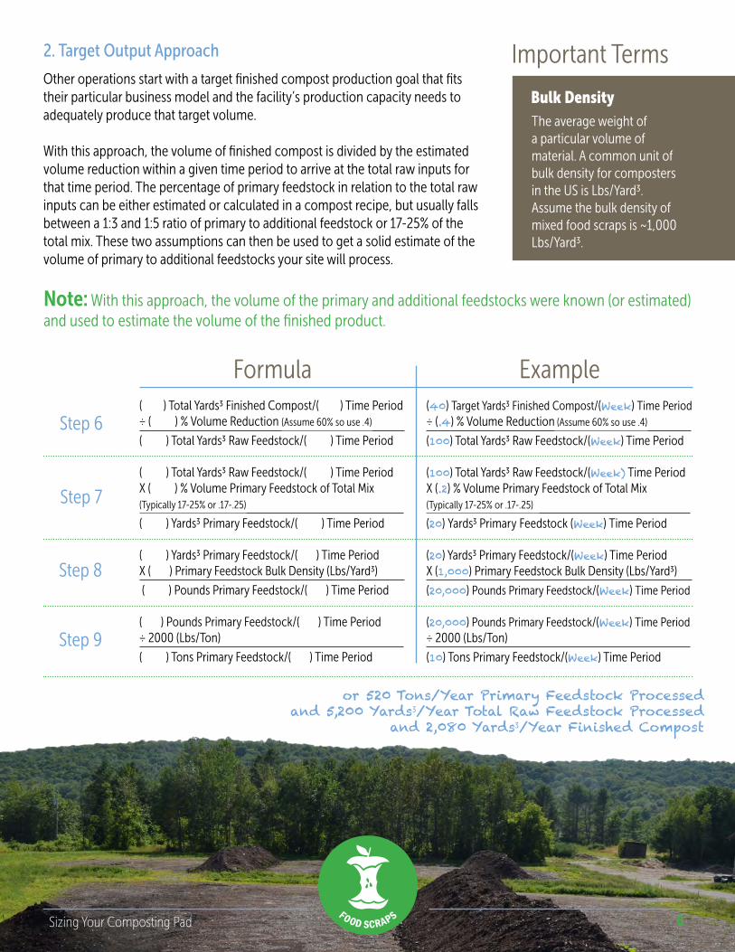
2. Target Output Approach
Other operations start with a target finished compost production goal that fits their particular business model and the facility’s production capacity needs to adequately produce that target volume.
With this approach, the volume of finished compost is divided by the estimated volume reduction within a given time period to arrive at the total raw inputs for that time period. The percentage of primary feedstock in relation to the total raw inputs can be either estimated or calculated in a compost recipe, but usually falls between a 1:3 and 1:5 ratio of primary to additional feedstock or 17-25% of the total mix. These two assumptions can then be used to get a solid estimate of the volume of primary to additional feedstocks your site will process.
( ) Total Yards3 Finished Compost/( ) Time Period÷ ( ) % Volume Reduction (Assume 60% so use .4)
( ) Total Yards3 Raw Feedstock/( ) Time Period
( ) Total Yards3 Raw Feedstock/( ) Time PeriodX ( ) % Volume Primary Feedstock of Total Mix(Typically 17-25% or .17-.25)
( ) Yards3 Primary Feedstock/( ) Time Period
( ) Yards3 Primary Feedstock/( ) Time Period X ( ) Primary Feedstock Bulk Density (Lbs/Yard3)
( ) Pounds Primary Feedstock/( ) Time Period
( ) Pounds Primary Feedstock/( ) Time Period÷ 2000 (Lbs/Ton)
( ) Tons Primary Feedstock/( ) Time Period
Step 6
Step 7
Step 9
Step 8
(40) Target Yards3 Finished Compost/(Week) Time Period÷ (.4) % Volume Reduction (Assume 60% so use .4)
(100) Total Yards3 Raw Feedstock/(Week) Time Period
(100) Total Yards3 Raw Feedstock/(Week) Time PeriodX (.2) % Volume Primary Feedstock of Total Mix(Typically 17-25% or .17-.25)
(20) Yards3 Primary Feedstock (Week) Time Period
(20) Yards3 Primary Feedstock/(Week) Time Period X (1,000) Primary Feedstock Bulk Density (Lbs/Yard3)
(20,000) Pounds Primary Feedstock/(Week) Time Period
(20,000) Pounds Primary Feedstock/(Week) Time Period÷ 2000 (Lbs/Ton)
(10) Tons Primary Feedstock/(Week) Time Period
Note: With this approach, the volume of the primary and additional feedstocks were known (or estimated) and used to estimate the volume of the finished product.
or 520 Tons/Year Primary Feedstock Processedand 5,200 Yards3/Year Total Raw Feedstock Processed
and 2,080 Yards3/Year Finished Compost
7Sizing Your Composting Pad
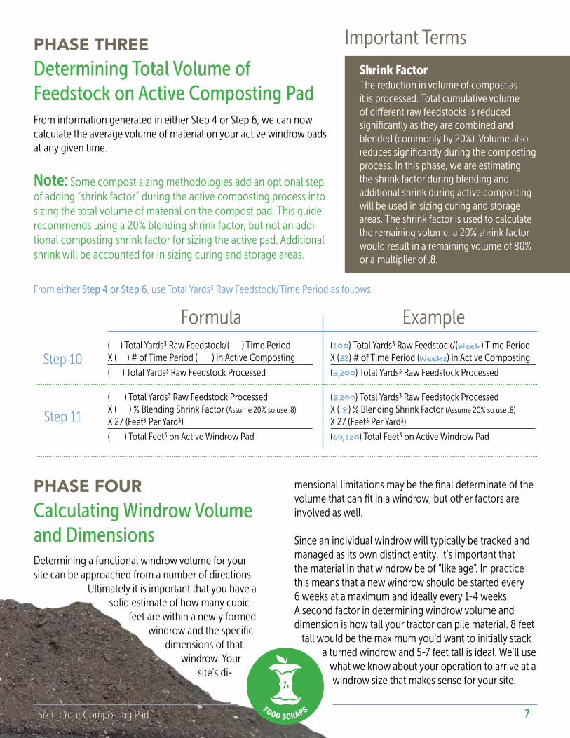
Determining Total Volume of Feedstock on Active Composting PadFrom information generated in either Step 4 or Step 6, we can now calculate the average volume of material on your active windrow pads at any given time.
Note: Some compost sizing methodologies add an optional step of adding “shrink factor” during the active composting process into sizing the total volume of material on the compost pad. This guide recommends using a 20% blending shrink factor, but not an addi-tional composting shrink factor for sizing the active pad. Additional shrink will be accounted for in sizing curing and storage areas.
Formula Example
PHASE THREE Important Terms
The reduction in volume of compost as it is processed. Total cumulative volume of different raw feedstocks is reduced significantly as they are combined and blended (commonly by 20%). Volume also reduces significantly during the composting process. In this phase, we are estimating the shrink factor during blending and additional shrink during active composting will be used in sizing curing and storage areas. The shrink factor is used to calculate the remaining volume; a 20% shrink factor would result in a remaining volume of 80% or a multiplier of .8.
Shrink Factor
( ) Total Yards3 Raw Feedstock/( ) Time PeriodX ( ) # of Time Period ( ) in Active Composting
( ) Total Yards3 Raw Feedstock Processed
( ) Total Yards3 Raw Feedstock ProcessedX ( ) % Blending Shrink Factor (Assume 20% so use .8)
X 27 (Feet3 Per Yard3)
( ) Total Feet3 on Active Windrow Pad
Step 10
Step 11
(100) Total Yards3 Raw Feedstock/(Week) Time PeriodX (32) # of Time Period (Weeks) in Active Composting
(3,200) Total Yards3 Raw Feedstock Processed
(3,200) Total Yards3 Raw Feedstock ProcessedX (.8) % Blending Shrink Factor (Assume 20% so use .8)
X 27 (Feet3 Per Yard3)
(69,120) Total Feet3 on Active Windrow Pad
From either Step 4 or Step 6, use Total Yards3 Raw Feedstock/Time Period as follows:
Calculating Windrow Volume and DimensionsDetermining a functional windrow volume for your site can be approached from a number of directions.
Ultimately it is important that you have a solid estimate of how many cubic
feet are within a newly formed windrow and the specific
dimensions of that windrow. Your
site’s di-
PHASE FOUR mensional limitations may be the final determinate of the volume that can fit in a windrow, but other factors are involved as well.
Since an individual windrow will typically be tracked and managed as its own distinct entity, it’s important that the material in that windrow be of “like age”. In practice this means that a new windrow should be started every 6 weeks at a maximum and ideally every 1-4 weeks. A second factor in determining windrow volume and dimension is how tall your tractor can pile material. 8 feet
tall would be the maximum you’d want to initially stack a turned windrow and 5-7 feet tall is ideal. We’ll use
what we know about your operation to arrive at a windrow size that makes sense for your site.
8Sizing Your Composting Pad
Use either Step 12a. OR Step 12b-12bb to determine the final number of Feet3/Windrow. Unless you are processing incoming feedstocks daily, Steps 12b-12bb are recommended, in order to reduce the need to split batches between separate wind-rows. You may use trial and error with Steps 12b-12bb, adjusting the time period per windrow, to find dimensions that work well for the site, while maintaining windrows with material of “like age” (e.g. 2 weeks of raw feedstocks per windrow).
Formula Example( ) Feet Windrow Length X ( ) Feet Windrow HeightX ( ) Feet Windrow Width (Assume Height X 2)
X .66 Cross Sectional Area (Assume .5 if Conservative)
( ) Average Feet3/Windrow
( ) Total Yards3 Raw Feedstock/( ) Time PeriodX ( ) Average # of Time Period ( ) /WindrowX ( ) % Blending Shrink Factor (20% reduction means multiply by .8)
X 27 (Feet3 Per Yard3)
( ) Average Feet3/Windrow
( ) Average Feet3/WindrowX ( ) Feet Windrow HeightX ( ) Feet Windrow Width (Assume Height X 2) ÷ .66 Cross Sectional Area (Assume .5 if Conservative)
( ) Feet Windrow Length
Step 12a
Step 12b
Step 12bb
(90) Feet Windrow Length X (6) Feet Windrow Height FeetX (12) Feet Windrow Width (Assume Height X 2)
X .66 Cross Sectional Area (Assume .5 if Conservative)
(4,277 or call it 4,300) Average Feet3/Windrow
(100) Total Yards3 Raw Feedstock/(Week) Time PeriodX (2) Average # of Time Period (Weeks)/WindrowX (.8) % Blending Shrink Factor (20% reduction means multiply by .8)
X 27 (Feet3 Per Yard3)
(4,320 or call it 4,300) Average Feet3/Windrow
(4,320 or call it 4,300) Average Feet3/WindrowX (6) Feet Windrow HeightX (12) Feet Windrow Width (Assume Height X 2)
÷ .66 Cross Sectional Area (Assume .5 if Conservative)
(90.5 or call it 90 Feet) Windrow Length
Calculating Number of Windrows on the Active Pad
PHASE FIVETo estimate the number of windrows on the active pad, simply divide the total volume of material on the active composting pad, by the volume per windrow as follows:
Formula Example( ) Total Feet3 on Active Windrow Pad (Step 11)÷ ( ) Average Feet3/Windrow (Step 11a or 11b)
( ) # of Windrows on Active Pad (Round)Step 13
(69,120) Total Feet3 on Active Windrow Pad (Step 11)÷ (4,300) Average Feet3/Windrow (Step 11a or 11b)
(16) # of Windrows on Active Pad (Round)
Determining Active Pad Workspace Needs
PHASE SIX
Turned windrow composting systems require “workspace” surrounding the pile. This space provides access for equipment used to turn the
windrows and space to travel around and in between the windrows. Loader turned windrows are most efficiently turned by “rolling” them from the side, although they can be moved from their ends as well (this is not an efficient
way to provide frequent aeration and mixing at any scale). Windrow turners and excavators typically
require less workspace between piles than loaders with a similar capacity, although tractor
9Sizing Your Composting Pad
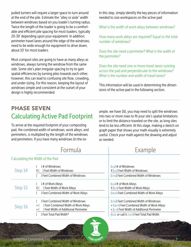
pulled turners will require a larger space to turn around at the end of the pile. Estimate the “alley or aisle” width between windrows based on you loader’s turning radius. Twice the length of the loader is going to be a comfort-able and efficient pile spacing for most loaders, typically 20-30’ depending upon your equipment. In addition, perimeter travel lanes around the edge of the windrows, need to be wide enough for equipment to drive down, about 10’ for most loaders.
Most compost sites are going to have as many alleys as windrows, always turning the windrow from the same side. Some site’s plan irregular spacing to try to gain spatial efficiencies by turning piles towards each other, however, this can lead to confusing site flow, crowding, and under sizing. For this reason, keeping the layout of windrows simple and consistent at the outset of your design is highly recommended.
In this step, simply identify the key pieces of information needed to size workspaces on the active pad:
What is the width of work alleys between windrows?
How many work alleys are required? Equal to the total number of windrows?
Does the site need a perimeter? What is the width of the perimeter?
Does the site need one or more travel lanes running across the pad and perpendicular to the windrows? What is the number and width of travel lanes?
This information will be used in determining the dimen-sions of the active pad in the following section.
Calculating Active Pad FootprintPHASE SEVEN
To arrive at the required footprint of your composting pad, the combined width of windrows, work alleys, and perimeters, is multiplied by the length of the windrows and perimeters. If you have many windrows (in the ex-
Formula Example
( ) # of WindrowsX ( ) Feet Width of Windrows
( ) Feet Combined Width of Windrows
( ) # of Work AlleysX ( ) Feet Width of Work Alleys
( ) Feet Combined Width of Work Alleys
( ) Feet Combined Width of Windrows+ ( ) Feet Combined Width of Work Alleys+ ( ) Feet Width of Additional Perimeter
( ) Feet Total Pad Width*
Step 14
Step 15
Step 16
(16) # of WindrowsX (12) Feet Width of Windrows
(192) Feet Combined Width of Windrows
(16) # of Work AlleysX (20) Feet Width of Work Alleys
(320) Feet Combined Width of Work Alleys (192) Feet Combined Width of Windrows+ (320) Feet Combined Width of Work Alleys+ (10) Feet Width of Additional Perimeter
(522 or call it 530) Feet Total Pad Width
Calculating the Width of the Pad
ample, we have 16), you may need to split the windrows into two or more rows to fit your site’s spatial limitations or to limit the distance traveled on the site, as long sites tend to be less efficient. At this stage, making a sketch on graph paper that shows your math visually is extremely useful. Check your math against the drawing and adjust as needed.
10Sizing Your Composting Pad
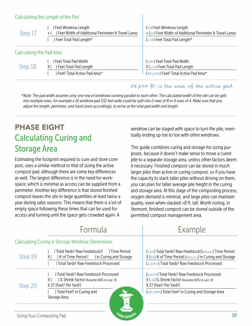
( ) Feet Windrow Length + ( ) Feet Width of Additional Perimeter & Travel Lanes
( ) Feet Total Pad Length*
( ) Feet Total Pad WidthX ( ) Feet Total Pad Length
( ) Feet2 Total Active Pad Area*
Step 17
Step 18
(90) Feet Windrow Length + (20) Feet Width of Additional Perimeter & Travel Lanes
(110) Feet Total Pad Length*
(530) Feet Total Pad WidthX (110) Feet Total Pad Length
(58,600) Feet2 Total Active Pad Area*
Calculating Curing and Storage Area
PHASE EIGHT
Estimating the footprint required to cure and store com-post, uses a similar method to that of sizing the active compost pad, although there are some key differences as well. The largest difference is in the need for work-space, which is minimal as access can be supplied from a perimeter. Another key difference is that stored finished compost leaves the site in large quantities at least twice a year during sales seasons. This means that there is a lot of empty space following these times that can be used for access and turning until the space gets crowded again. A
Calculating the Length of the Pad
Calculating the Pad Area
58,600 ft2 is the area of the active pad
* Note: The pad width assumes only one row of windrows running parallel to each other. The calculated width of the site can be split into multiple rows, for example a 16 windrow pad 532 feet wide could be split into 2 rows of 8 or 4 rows of 4. Make sure that you adjust the length, perimeter, and travel lanes accordingly, to arrive at the total pad width and length.
windrow can be staged with space to turn the pile, even-tually ending up toe to toe with other windrows.
This guide combines curing and storage for sizing pur-poses, because it doesn’t make sense to move a cured pile to a separate storage area, unless other factors deem it necessary. Finished compost can be stored in much larger piles than active or curing compost, so if you have the capacity to stack taller piles without driving on them, you can plan for taller average pile height in the curing and storage area. At this stage of the composting process, oxygen demand is minimal, and large piles can maintain quality, even when stacked >8 ft. tall. Worth noting, in Vermont, finished compost can be stored outside of the permitted compost management area.
Formula Example
( ) Total Yards3 Raw Feedstock/( ) Time PeriodX ( ) # of Time Period ( ) in Curing and Storage
( ) Total Yards3 Raw Feedstock Processed
( ) Total Yards3 Raw Feedstock ProcessedX ( ) % Shrink Factor (Assume 60% so use .4)
X 27 (Feet3 Per Yard3)
( ) Total Feet3 in Curing and Storage Area
Step 19
Step 20
(100) Total Yards3 Raw Feedstock/(Week) Time PeriodX (26) # of Time Period (Weeks) in Curing and Storage
(2,400) Total Yards3 Raw Feedstock Processed (2,600) Total Yards3 Raw Feedstock ProcessedX (.4) % Shrink Factor (Assume 60% so use .4)
X 27 (Feet3 Per Yard3)
(28,080) Total Feet3 in Curing and Storage Area
Calculating Curing & Storage Windrow Dimensions
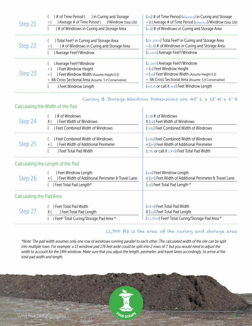
11Sizing Your Composting Pad
( ) # of Time Period ( ) in Curing and Storage÷ ( ) Average # of Time Period ( )/Windrow (Step 12b)
( ) # of Windrows in Curing and Storage Area
( ) Total Feet3 in Curing and Storage Area÷ ( ) # of Windrows in Curing and Storage Area
( ) Average Feet3/Windrow
( ) Average Feet3/Windrow÷ ( ) Feet Windrow Height÷ ( ) Feet Windrow Width (Assume Height X 2) ÷ .66 Cross Sectional Area (Assume .5 if Conservative)
( ) Feet Windrow Length
Step 21
Step 22
Step 23
(26) # of Time Period (Weeks) in Curing and Storage÷ (2) Average # of Time Period (Weeks)/Windrow (Step 12b)
(13) # of Windrows in Curing and Storage Area
(28,080) Total Feet3 in Curing and Storage Area÷ (13) # of Windrows in Curing and Storage Area
(2,160) Average Feet3/Windrow
(2,160) Average Feet3/Windrow÷ (6) Feet Windrow Height÷ (12) Feet Windrow Width (Assume Height X 2) ÷ .66 Cross Sectional Area (Assume .5 if Conservative)
(45.5 or call it 45) Feet Windrow Length
Curing & Storage Windrow Dimensions are 45’ L x 12’ W x 6’ H
( ) # of WindrowsX ( ) Feet Width of Windrows
( ) Feet Combined Width of Windrows
( ) Feet Combined Width of Windrows+ ( ) Feet Width of Additional Perimeter
( ) Feet Total Pad Width
( ) Feet Windrow Length + ( ) Feet Width of Additional Perimeter & Travel Lane
( ) Feet Total Pad Length*
( ) Feet Total Pad WidthX ( ) Feet Total Pad Length
( ) Feet2 Total Curing/Storage Pad Area *
Step 24
Step 25
Step 26
(13) # of WindrowsX (12) Feet Width of Windrows
(156) Feet Combined Width of Windrows
(156) Feet Combined Width of Windrows+ (20) Feet Width of Additional Perimeter
(176 or call it 180) Feet Total Pad Width
(45) Feet Windrow Length + (20) Feet Width of Additional Perimeter & Travel Lane
(65) Feet Total Pad Length *
(180) Feet Total Pad WidthX (65) Feet Total Pad Length
(11,700) Feet2 Total Curing/Storage Pad Area *
Calculating the Width of the Pad
Calculating the Length of the Pad
Calculating the Pad Area
Step 27
11,700 ft2 is the area of the curing and storage area
*Note: The pad width assumes only one row of windrows running parallel to each other. The calculated width of the site can be split into multiple rows. For example: a 13 windrow pad 176 feet wide could be split into 2 rows of 7, but you would need to adjust the width to account for the 14th windrow. Make sure that you adjust the length, perimeter, and travel lanes accordingly, to arrive at the total pad width and length.
12Sizing Your Composting Pad
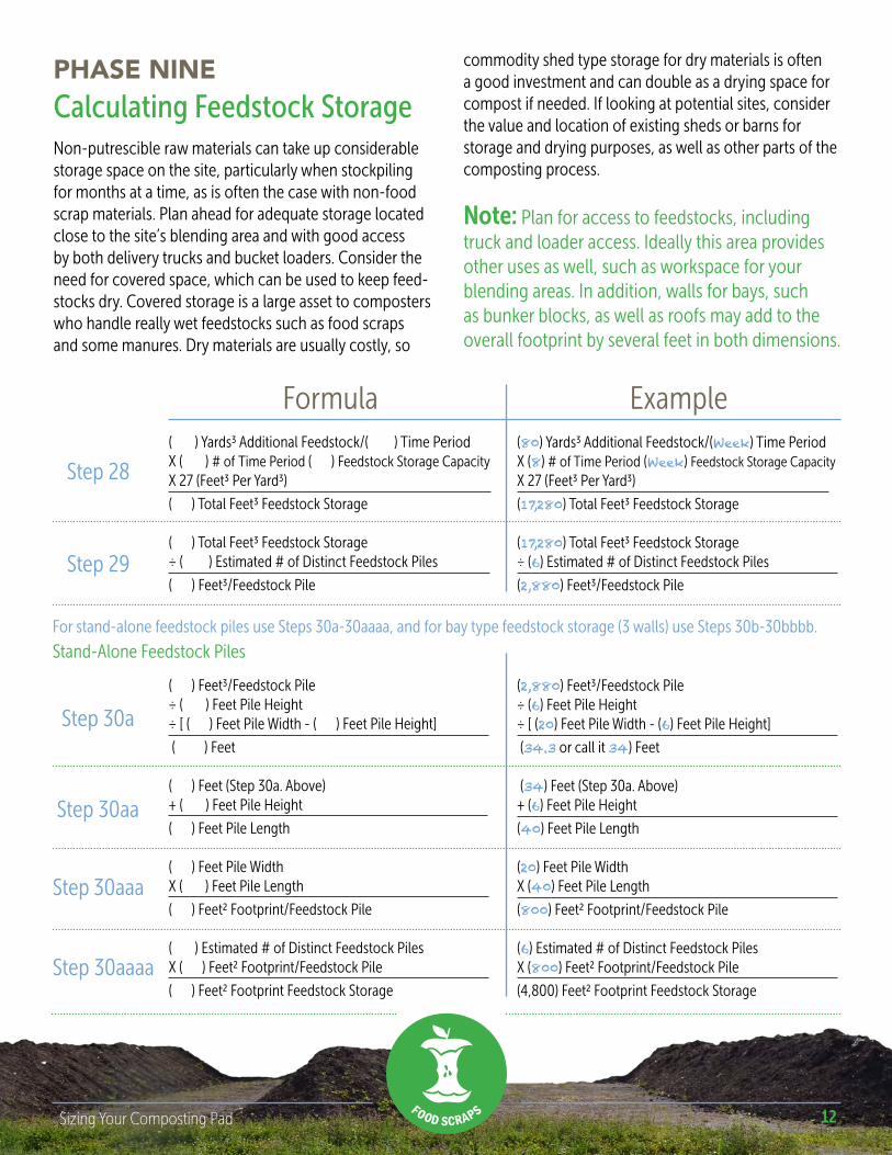
Calculating Feedstock StoragePHASE NINE
Non-putrescible raw materials can take up considerable storage space on the site, particularly when stockpiling for months at a time, as is often the case with non-food scrap materials. Plan ahead for adequate storage located close to the site’s blending area and with good access by both delivery trucks and bucket loaders. Consider the need for covered space, which can be used to keep feed-stocks dry. Covered storage is a large asset to composters who handle really wet feedstocks such as food scraps and some manures. Dry materials are usually costly, so
Formula Example( ) Yards3 Additional Feedstock/( ) Time PeriodX ( ) # of Time Period ( ) Feedstock Storage CapacityX 27 (Feet3 Per Yard3)
( ) Total Feet3 Feedstock Storage
( ) Total Feet3 Feedstock Storage÷ ( ) Estimated # of Distinct Feedstock Piles
( ) Feet3/Feedstock Pile
Step 28
Step 29
(80) Yards3 Additional Feedstock/(Week) Time PeriodX (8) # of Time Period (Week) Feedstock Storage CapacityX 27 (Feet3 Per Yard3)
(17,280) Total Feet3 Feedstock Storage
(17,280) Total Feet3 Feedstock Storage÷ (6) Estimated # of Distinct Feedstock Piles
(2,880) Feet3/Feedstock Pile
Stand-Alone Feedstock Piles
commodity shed type storage for dry materials is often a good investment and can double as a drying space for compost if needed. If looking at potential sites, consider the value and location of existing sheds or barns for storage and drying purposes, as well as other parts of the composting process.
Note: Plan for access to feedstocks, including truck and loader access. Ideally this area provides other uses as well, such as workspace for your blending areas. In addition, walls for bays, such as bunker blocks, as well as roofs may add to the overall footprint by several feet in both dimensions.
For stand-alone feedstock piles use Steps 30a-30aaaa, and for bay type feedstock storage (3 walls) use Steps 30b-30bbbb.
( ) Feet3/Feedstock Pile÷ ( ) Feet Pile Height÷ [ ( ) Feet Pile Width - ( ) Feet Pile Height]
( ) Feet
( ) Feet (Step 30a. Above) + ( ) Feet Pile Height
( ) Feet Pile Length
( ) Feet Pile WidthX ( ) Feet Pile Length
( ) Feet2 Footprint/Feedstock Pile
( ) Estimated # of Distinct Feedstock PilesX ( ) Feet2 Footprint/Feedstock Pile
( ) Feet2 Footprint Feedstock Storage
Step 30a
Step 30aa
(2,880) Feet3/Feedstock Pile÷ (6) Feet Pile Height÷ [ (20) Feet Pile Width - (6) Feet Pile Height]
(34.3 or call it 34) Feet
(34) Feet (Step 30a. Above) + (6) Feet Pile Height
(40) Feet Pile Length
(20) Feet Pile WidthX (40) Feet Pile Length
(800) Feet2 Footprint/Feedstock Pile
(6) Estimated # of Distinct Feedstock PilesX (800) Feet2 Footprint/Feedstock Pile
(4,800) Feet2 Footprint Feedstock Storage
Step 30aaa
Step 30aaaa
13Sizing Your Composting Pad
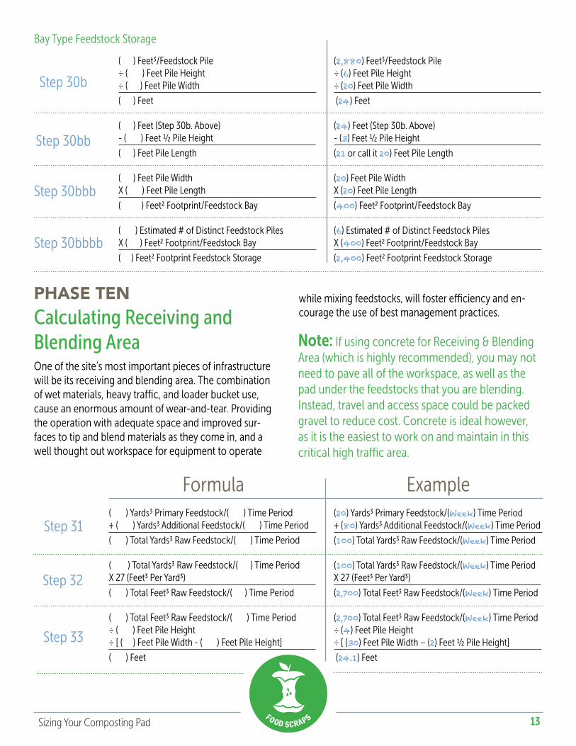
Bay Type Feedstock Storage
( ) Feet3/Feedstock Pile÷ ( ) Feet Pile Height÷ ( ) Feet Pile Width
( ) Feet
( ) Feet (Step 30b. Above) - ( ) Feet ½ Pile Height
( ) Feet Pile Length
( ) Feet Pile WidthX ( ) Feet Pile Length
( ) Feet2 Footprint/Feedstock Bay
( ) Estimated # of Distinct Feedstock PilesX ( ) Feet2 Footprint/Feedstock Bay
( ) Feet2 Footprint Feedstock Storage
Step 30b
Step 30bb
(2,880) Feet3/Feedstock Pile÷ (6) Feet Pile Height÷ (20) Feet Pile Width
(24) Feet
(24) Feet (Step 30b. Above) - (3) Feet ½ Pile Height
(21 or call it 20) Feet Pile Length
(20) Feet Pile WidthX (20) Feet Pile Length
(400) Feet2 Footprint/Feedstock Bay
(6) Estimated # of Distinct Feedstock PilesX (400) Feet2 Footprint/Feedstock Bay
(2,400) Feet2 Footprint Feedstock Storage
Step 30bbb
Step 30bbbb
Calculating Receiving and Blending Area
PHASE TEN
One of the site’s most important pieces of infrastructure will be its receiving and blending area. The combination of wet materials, heavy traffic, and loader bucket use, cause an enormous amount of wear-and-tear. Providing the operation with adequate space and improved sur-faces to tip and blend materials as they come in, and a well thought out workspace for equipment to operate
while mixing feedstocks, will foster efficiency and en-courage the use of best management practices.
Note: If using concrete for Receiving & Blending Area (which is highly recommended), you may not need to pave all of the workspace, as well as the pad under the feedstocks that you are blending. Instead, travel and access space could be packed gravel to reduce cost. Concrete is ideal however, as it is the easiest to work on and maintain in this critical high traffic area.
Formula Example( ) Yards3 Primary Feedstock/( ) Time Period + ( ) Yards3 Additional Feedstock/( ) Time Period
( ) Total Yards3 Raw Feedstock/( ) Time Period
( ) Total Yards3 Raw Feedstock/( ) Time PeriodX 27 (Feet3 Per Yard3)
( ) Total Feet3 Raw Feedstock/( ) Time Period
( ) Total Feet3 Raw Feedstock/( ) Time Period÷ ( ) Feet Pile Height÷ [ ( ) Feet Pile Width - ( ) Feet Pile Height]
( ) Feet
Step 31
Step 32
Step 33
(20) Yards3 Primary Feedstock/(Week) Time Period + (80) Yards3 Additional Feedstock/(Week) Time Period
(100) Total Yards3 Raw Feedstock/(Week) Time Period
(100) Total Yards3 Raw Feedstock/(Week) Time PeriodX 27 (Feet3 Per Yard3)
(2,700) Total Feet3 Raw Feedstock/(Week) Time Period
(2,700) Total Feet3 Raw Feedstock/(Week) Time Period÷ (4) Feet Pile Height÷ [ (30) Feet Pile Width – (2) Feet ½ Pile Height]
(24.1) Feet
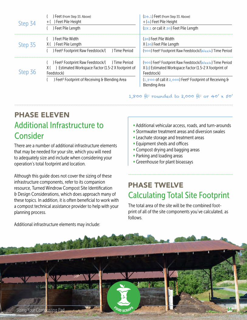
14Sizing Your Composting Pad
( ) Feet (From Step 33. Above)
+ ( ) Feet Pile Height
( ) Feet Pile Length
( ) Feet Pile WidthX ( ) Feet Pile Length
( ) Feet2 Footprint Raw Feedstock/( ) Time Period
( ) Feet2 Footprint Raw Feedstock/( ) Time PeriodX ( ) Estimated Workspace Factor (1.5-2 X footprint ofFeedstock)
( ) Feet2 Footprint of Receiving & Blending Area
Step 34
Step 35
Step 36
(24.1) Feet (From Step 33. Above)
+ (4) Feet Pile Height
(28.1 or call it 30) Feet Pile Length
(30) Feet Pile WidthX (30) Feet Pile Length
(900) Feet2 Footprint Raw Feedstock/(Week) Time Period
(900) Feet2 Footprint Raw Feedstock/(Week) Time PeriodX (2) Estimated Workspace Factor (1.5-2 X footprint ofFeedstock)
(1,800 of call it 2,000) Feet2 Footprint of Receiving & Blending Area
1,800 ft2 rounded to 2,000 ft2 or 40’ x 50’
Additional Infrastructure to Consider
PHASE ELEVEN
There are a number of additional infrastructure elements that may be needed for your site, which you will need to adequately size and include when considering your operation’s total footprint and location.
Although this guide does not cover the sizing of these infrastructure components, refer to its companion resource, Turned Windrow Compost Site Identification & Design Considerations, which does approach many of these topics. In addition, it is often beneficial to work with a compost technical assistance provider to help with your planning process.
Additional infrastructure elements may include:
∞ Additional vehicular access, roads, and turn-arounds∞ Stormwater treatment areas and diversion swales∞ Leachate storage and treatment areas∞ Equipment sheds and offices∞ Compost drying and bagging areas∞ Parking and loading areas∞ Greenhouse for plant bioassays
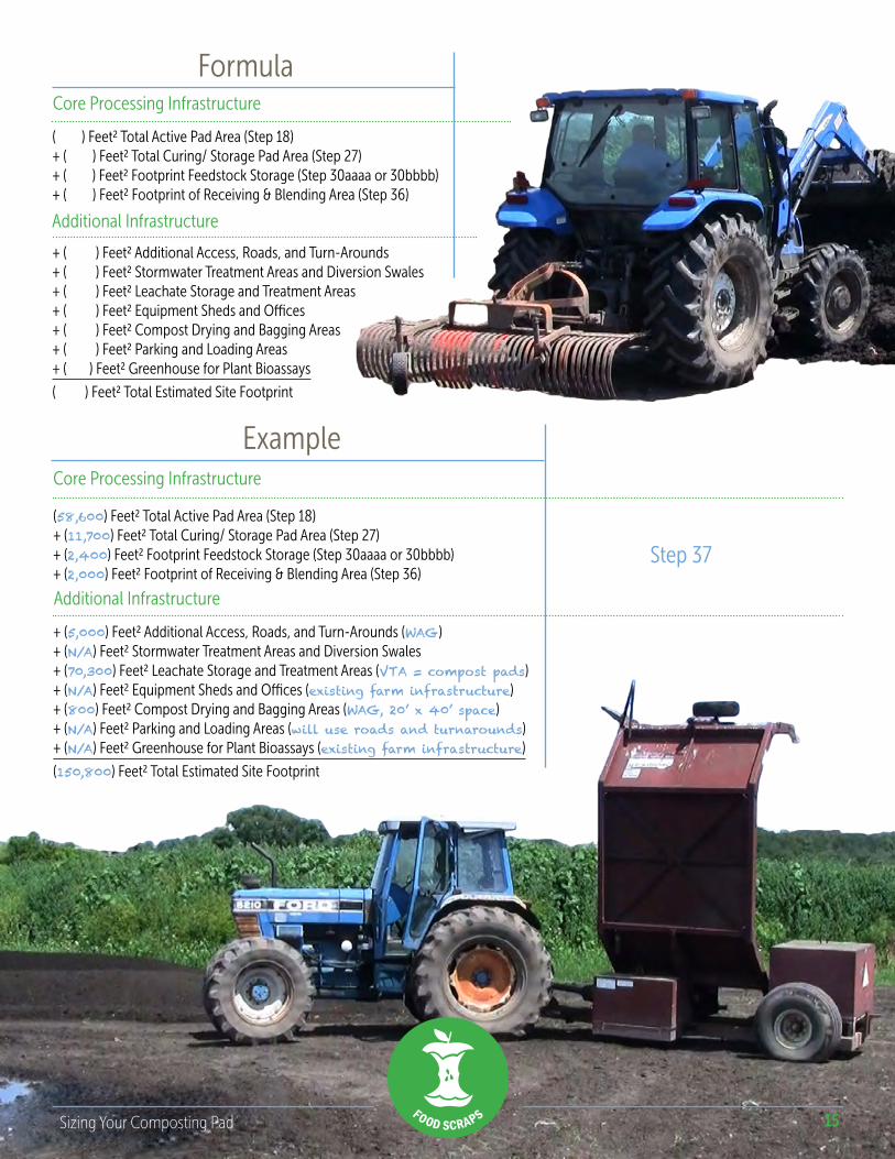
Calculating Total Site Footprint PHASE TWELVE
The total area of the site will be the combined foot-print of all of the site components you’ve calculated, as follows.
15Sizing Your Composting Pad
Formula
Step 37
( ) Feet2 Total Active Pad Area (Step 18)+ ( ) Feet2 Total Curing/ Storage Pad Area (Step 27)+ ( ) Feet2 Footprint Feedstock Storage (Step 30aaaa or 30bbbb)+ ( ) Feet2 Footprint of Receiving & Blending Area (Step 36)
+ ( ) Feet2 Additional Access, Roads, and Turn-Arounds + ( ) Feet2 Stormwater Treatment Areas and Diversion Swales+ ( ) Feet2 Leachate Storage and Treatment Areas + ( ) Feet2 Equipment Sheds and Offices + ( ) Feet2 Compost Drying and Bagging Areas + ( ) Feet2 Parking and Loading Areas + ( ) Feet2 Greenhouse for Plant Bioassays
( ) Feet2 Total Estimated Site Footprint
(58,600) Feet2 Total Active Pad Area (Step 18)+ (11,700) Feet2 Total Curing/ Storage Pad Area (Step 27)+ (2,400) Feet2 Footprint Feedstock Storage (Step 30aaaa or 30bbbb)+ (2,000) Feet2 Footprint of Receiving & Blending Area (Step 36)
+ (5,000) Feet2 Additional Access, Roads, and Turn-Arounds (WAG)+ (N/A) Feet2 Stormwater Treatment Areas and Diversion Swales+ (70,300) Feet2 Leachate Storage and Treatment Areas (VTA = compost pads)+ (N/A) Feet2 Equipment Sheds and Offices (existing farm infrastructure)+ (800) Feet2 Compost Drying and Bagging Areas (WAG, 20’ x 40’ space)+ (N/A) Feet2 Parking and Loading Areas (will use roads and turnarounds) + (N/A) Feet2 Greenhouse for Plant Bioassays (existing farm infrastructure)
(150,800) Feet2 Total Estimated Site Footprint
Example
Additional Infrastructure
Core Processing Infrastructure
Core Processing Infrastructure
Additional Infrastructure
16Sizing Your Composting Pad
ReferencesSite Identification and Development. Highfields Center for Composting. Hardwick, VT. Web Resource: No longer available.
Rynk, R. On-Farm Composting Handbook. NRAES 54. Ithaca, NY. Natural Resource, Agriculture, and Engineering Service. 1992.
Vermont Solid Waste Management Rules: Subchapter 11 - ORGANICS MANAGEMENT. Effective Date 3/15/2012.
Growing Local Fertility: A Guide to Community Composting. Highfields Center for Composting and Institute of Local Self Reliance. 2014. Web Resource: Retrieved April 29, 2015.
This guide was created under contract with the Vermont Agency of Natural Resources, Department of Environmental Conservation, Solid Waste Program, in 2015. Any opinions, findings, and conclusions or recommendations expressed in these materials are solely the responsibility of the authors and do not necessarily represent the official views of the Agency of Natural Resources.
The following resource uses or is adapted from con-tent originally developed by the Highfields Center for Composting in Hardwick VT. The Highfields Center for Composting dissolved as an organization in December 2014 and ended its active involvement in the Close the Loop Program. The content has been made publically available for use in supporting organics management in Vermont and elsewhere through the generosity of the High Meadows Fund, the Harris and Frances Block Foundation, and the Vermont Community Foundation. For more information about the use of Highfields related materials please contact [email protected].
Content Creator
DesignPhotos∞ Highfields Center For Composting∞ Srise
Acknowledgements
www.CompostTechnicalServices.com
www.srise.com
Solid Waste Management ProgramWaste Management & Prevention Division1 National Life Dr – Davis 1 Montpelier VT 05620-3704(802)828-1138www.recycle.vermont.gov
For more information contact
16
James McSweeney
The Vermont community wishes to thank the Highfields Center for Composting for its years of outstanding leadership in the service of community composting and universal recycling in Vermont.