the system would comprise - indwe environmental … · o sludge drying beds ... configuration will...
TRANSCRIPT

Prelim design report - August 2013 - Rev 0 2 Rev 0 /August 2013
• The system would comprise : o head of works o up-flow anaerobic sludge blanket reactor o primary aerobic pond o four secondary aerobic ponds o aquatic pond o anaerobic digestion pond o sludge drying beds
At this meeting it was suggested that a pump station be constructed on the site currently occupied by the package plant, and it was recommended that an inlet works be constructed ahead of the pump station, to condition the sewage before it is pumped to the proposed pond system. At the conclusion of the meeting it was decided that potential pond sites would be investigated using Google Earth and topographical maps, followed by a site visit. Land issues pertaining to the proposed sites were to be investigated – including matters such as ownership, zoning, alignment with the municipality’s Spatial Development Plan, as well as the existence of any potential land claims. A report covering the potential pond sites was submitted in June 2013. The following report deals with the preliminary design of the pond system and includes a summary of the operational procedures and estimated operational costs.

Prelim design report - August 2013 - Rev 0 3 Rev 0 /August 2013
2 SITE LOCATION AND DESCRIPTION
2.1 Geographical Location
Ngqushwa Municipality, comprising 14 wards, is situated within the Amathole District Municipality and is an amalgamation of the districts of Peddie, Hamburg and a portion of the King William’s Town district. In the sub-regional context, Ngqushwa Municipality is situated in the western portion of the Amathole District Municipality area. It is made up of two urban centres (Peddie and Hamburg) and 120 rural villages. Peddie falls in Ward 11. Peddie is the Municipal seat and is located along the King William’s Town and Grahamstown N2 road. It is 53 km from King William’s Town and 68 km from Grahamstown.
2.2 Climate
Peddie lies on the boundary between the coastal zone and the coastal plateau zone. The climate can be summarised as cool sub–tropical with warm summers and cool winters. Average annual rainfall is 500 mm distributed predominantly during the summer months between October and June, but rainfall is erratic. The average monthly temperature and rainfall figures for Bathurst (± 50 km south-west of Peddie) are presented in Table 2.1 below. Table 2.1: Average Monthly Climatic Data measured a t Bathurst (1993 – 2002)
Month Average Maximum Temperature (0C)
Average Minimum Temperature (0C)
Average
Rainfall (mm)
January 26.2 17.4 71.82
February 27.1 17.9 39.88
March 26.0 17.1 85.77
April 24.2 15.1 53.89
May 22.9 13.1 22.92
June 21.7 11.2 28.19
July 21.2 10.5 41.71
August 21.4 11.1 51.53
September 21.9 12.0 58.66
October 22.5 13.3 61.09
November 23.8 14.6 74.79
December 25.3 16.4 87.12

Prelim design report - August 2013 - Rev 0 4 Rev 0 /August 2013
3 EXISTING INFRASTRUCTURE
3.1 Existing Sanitation Services
A description of the existing waterborne and on-site sanitation services and, where applicable, their serviceability and sufficiency, is discussed in the “Sanitation Master Plan Report” compiled by Arcus GIBB (May 2005).
3.2 Existing Levels of Sanitation Service
A summary of the existing levels of sanitation service in Peddie is shown in Table 3.1 below.
Table 3.1: Summary of Existing Sanitation Services for Peddie
Area Number of developed erven
Type of Sanitation Level of Service
Peddie Town 288 Waterborne (1) Above RDP standards
Peddie Extension A 550 VIP latrines Equal to RDP standards
Peddie Extension B 1420 Waterborne Above RDP standards
Durban Village 156 VIP latrines Equal to RDP standard
Septic tanks Above RDP standard
Ordinary pit latrines Below RDP standard
German Village 2 Ordinary pit latrines Below RDP standards
(1) Only approximately 40% of developed erven are actually connected to the sewers at this stage
3.3 Existing Wastewater Treatment Works (WWTW)
An extended aeration sewage treatment plant was constructed in Peddie in 1997. The works is located in the public open space on the eastern side of the N2 next to the Ngqushwa River. The works was designed for a hydraulic capacity of 250 kℓ/day and a BOD capacity of 125 kg/day. Currently the works is overloaded and the effluent is not complying with the “General Limits” as set out by Section 21 of the National Water Act.

Prelim design report - August 2013 - Rev 0 5 Rev 0 /August 2013
4 POPULATION AND ESTIMATED HYDRAULIC AND BIOLOGICAL LOADING
Table 4.1 is a summary of the population and their contribution to the WWTW as set out in the “Peddie Sanitation Master Plan”, Arcus GIBB, March 2005.
Table 4.1: Population Growth, Hydraulic and Biologi cal Loading to Proposed WWTW
Capita
contributing to WWTW flows
ADWF (kl/day)
BOD (kg/day)
TKN (kg/d)
Comment
Present situation 1033 73 53 142
Future situation (for immediate
development)
9693 673 503 1112
Proposed WWTW 12186 1000 650 1134 The proposed WWTW will cater for population
growth up to 2015
Future situation (for ultimate
development)
18537 1833 1023 2079 The proposed WWTW will cater for population
growth up to 2032
Year Population Assumed growth rate per year = 2.50%
2007 9935
2008 10184
2009 10438
2010 10699
2011 10967
2012 11241
2013 11522
2014 11810
2015 12105
2016 12408
2017 12718
2018 13036
2019 13362
2020 13696
2021 14038
2022 14389
2023 14749
2024 15118
2025 15496
2026 15883
2027 16280
2028 16687
2029 17104
2030 17532
2031 17970
2032 18420

Prelim design report - August 2013 - Rev 0 6 Rev 0 /August 2013
By 2015 – 2016 the population is projected to increase to approximately 12 105 people which will generate a total flow to the proposed works of 1 000 kℓ/day. To provide capacity in the WWTW pond system for the next 20 years, a 2 000 kℓ/day plant is proposed, which will cater for flows beyond the year 2035.

Prelim design report - August 2013 - Rev 0 7 Rev 0 /August 2013
5 PROPOSED INFRASTRUCTURE
5.1 General
In planning the proposed scheme, GIBB adopted the population and flow estimates from the Sanitation Master Plan Report, March 2005. These figures correlate with the guidelines set out by the “Red Book” (Guidelines for the Provision of Engineering Services and Amenities in Residential Township Development).
5.2 Wastewater Treatment Unit Process
The proposed wastewater treatment process is a combination between an Up-flow Anaerobic Sludge Blanket Reactor, a Facultative-Aerobic Pond System and a Floating Aquatic Pond. The proposed WWTW has a capacity of 2 000 kℓ/day ADWF and an average daily organic load of 2 268 kg COD/day. The WWTW is designed to treat domestic sewage. The proposed WWTW consists of the following unit process components: Primary Treatment
a) Inlet works (including screening, de-gritting and inflow measurement) b) Up-flow anaerobic sludge blanket reactor (2x)
Secondary Treatment
a) Primary facultative pond (1x) b) Secondary facultative pond (1x) c) Tertiary facultative pond (3x)
Tertiary Treatment
a) Floating aquatic pond (1x) b) Disinfection of the final effluent
Sludge Handling
a) Anaerobic sludge reactor b) Sludge drying beds

Prelim design report - August 2013 - Rev 0 8 Rev 0 /August 2013
5.2.1 Primary Treatment
(a) Inlet Works Duty/standby, dual, coarse and fine hand raked screens will be installed in the inlet works. Three horizontal grit channels will allow for gravity grit settling and manual grit removal. Provision will be made to store and remove screenings and grit by means of waste bins and an accompanying trailer. Open channel venturi flume measurement will ensure continuous flow measurement. The flow metering records will allow for proper planning of future upgrades. The works is sized based on the existing and future domestic sewage loads from the local community. The design hydraulic capacity of the inlet works is 2000 kl/day ADWF (4000 kl/day PDWF and 6000 kl/day PWWF). The works will therefore have sufficient capacity for any foreseeable future WWTW upgrade in terms of capacity. Design flow velocity through the inlet works will be between 0.6 to 1.0 m/s for average to peak flow conditions. The grit channels will be designed for flow through velocities of between 0.3 to 0.4 m/s.
(b) Up-flow Anaerobic Sludge Blanket Reactor (UASBR) A dual configuration UASBR will be constructed to reduce major organic COD loads, in order to minimise pond surface area. The UASBR will also initiate anaerobic sludge digestion, which can reduce anaerobic sludge reactor size. The screened/degritted sewage will enter the UASBR at the bottom and flow to the top through the anaerobic sludge blanket. The overflow will proceed to the secondary treatment. The dual configuration will allow for flexibility during reactor maintenance and sludge withdrawal periods. The reactors will have three sludge withdrawal points, at different levels, to allow the operator to optimally determine sludge blanket level. Sludge withdrawn from the bottom of the UASBR will be introduced hydraulically into the bottom of the Anaerobic Sludge Reactor (ASR). General technical information on the UASBR; - Up-flow velocity; 0.9 m/h (at PWWF) - Surface area; 185m2/reactor - Volume; 667m3/reactor - Reactor depth; 3.6m

Prelim design report - August 2013 - Rev 0 9 Rev 0 /August 2013
5.2.2 Secondary Treatment
(a) Primary Facultative Pond The one primary pond will operate as a facultative oxidation pond. The pond capacity is designed incorporating the UASBR as a main COD load reducer. Overflow from the UASBR will enter the primary pond on the surface at one side and will flow diagonally to the other side of the pond. Effluent will exit the pond via a weir and proceed to the secondary pond. General technical information on the Primary Pond; - COD Loading; 4-12 kgCOD/m3/day - Detention time; 4-12 hours - COD Removal: 75-85% - Surface area; 25 000m2 - Volume; 30 000m3 - Pond depth; 1.2m
(b) Secondary Facultative Pond
The one secondary pond will operate as a facultative oxidation pond. Outflow from the primary pond will enter the secondary pond on the surface at one side and will flow diagonally to the other side of the pond. Effluent will exit the pond via a weir and proceed to the 1st tertiary pond. General technical information on the Secondary Pond; - COD Loading; 4-12 kgCOD/m3/day - Detention time; 4-12 hours - COD Removal: 75-85% - Surface area; 16 667m2 - Volume; 20 000m3 - Pond depth; 1.2m
(c) 1st, 2nd and 3rd Tertiary Facultative Ponds The three tertiary ponds will operate as facultative oxidation ponds. Outflow from the secondary pond will enter the tertiary pond on the surface at one side and will flow diagonally to the other side of the pond. Effluent will exit the pond via a weir and proceed to the floating aquatic pond. A duty/standby pump set will allow recycle from the secondary pond effluent to the primary pond inlet. The pump set will optimally allow for a flow between 23-46 ℓ/s. General technical information on the three Tertiary Ponds; - COD Loading; 4-12 kg COD/m3/day/pond - Detention time; 4-12 hours/pond - COD Removal: 75-85%/pond - Surface area; 8 333m2/pond - Volume; 10 000m3/pond - Pond depth; 1.2m

Prelim design report - August 2013 - Rev 0 10 Rev 0 /August 2013
5.2.3 Tertiary Treatment
(a) Floating Aquatic Pond The one floating aquatic pond will operate as a polishing treatment, utilizing harvest-able aquatic plants. Outflow from the last tertiary pond will enter the aquatic pond on the surface at one side and will flow diagonally to the other side of the pond. Effluent will exit the pond via a weir and proceed to the final effluent discharge structure. The accumulating plants must be harvested to make space for new plants. General technical information on the one Floating Aquatic Pond; - Surface area loading; 1.9 ha/1000m3/day - Surface area; 39 920m2 - Volume; 47 904m3 - Pond depth; 1.8m
(b) Disinfection of the Final Effluent A chlorination system will be used to dose chlorine into the water from the aquatic pond. The chlorine dosage shall not be less than 8 mg/ℓ, to give the required amount of chlorine residual, which shall not be less than 1,0 mg/ℓ under all hydraulic conditions. The proposed chlorine contact tank will be designed to give a minimum contact time of 20 minutes. General technical information on the Chlorine Contact Tank; - Tank volume; 90m3 - Minimum Flow (ADWF); 8 ℓ/s - Maximum Flow (PDWF); 57 ℓ/s
5.2.4 Sludge Handling
(a) Anaerobic Sludge Reactor (ASR) The sludge withdrawn from the UASBR will be discharged to an open anaerobic sludge reactor. The inflow sludge will be introduced periodically, at six different inflows, located towards the bottom of the side walls of the reactor. The ASR will make provision for two digested sludge withdrawal points, positioned centrally in relation to the six inlets. Overflow from the surface will be returned to the oxidation pond system. The withdrawn digested sludge will be discharged onto sludge drying beds for solar drying. General technical information on the one Anaerobic Sludge Reactor; - Surface area; 857m2 - Volume; 3 000m3 - Pond depth; 3.5m

Prelim design report - August 2013 - Rev 0 11 Rev 0 /August 2013
(b) Sludge Drying Beds The anaerobic digested sludge is dewatered by being hydraulically discharged onto the sludge drying beds. The sludge is left for the supernatant and sludge to separate before decanting the supernatant to the oxidation system. The sludge is then further dried by means of solar energy. General technical information on the four Sludge Drying Beds; - Surface area; 500m2/bed - Volume; 225m3/bed - Bed depth; 450mm
5.2.5 Irrigation Pumps As a future option, irrigation pumps could be installed. This is not necessary in terms of the proposed process, but could add value in terms of providing irrigation water to the community.
Prelim design report - August 2013 - Rev 0 12 Rev 0 /August 2013
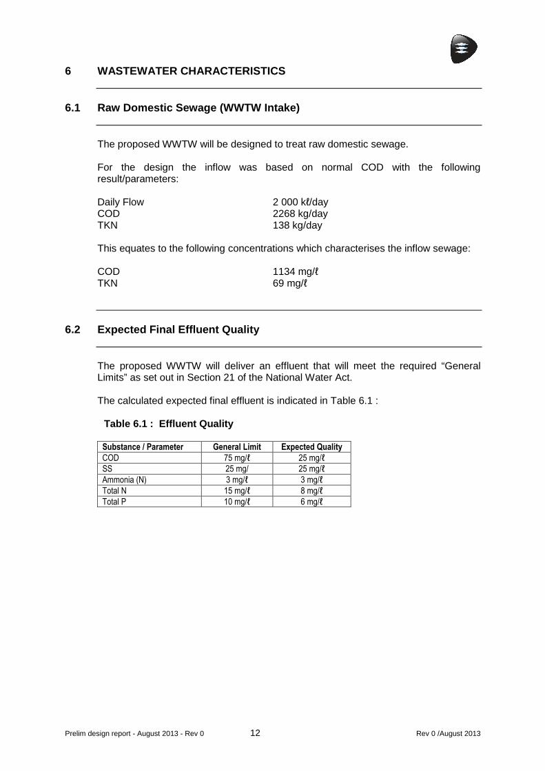
6 WASTEWATER CHARACTERISTICS
6.1 Raw Domestic Sewage (WWTW Intake)
The proposed WWTW will be designed to treat raw domestic sewage. For the design the inflow was based on normal COD with the following result/parameters: Daily Flow 2 000 kℓ/day COD 2268 kg/day TKN 138 kg/day This equates to the following concentrations which characterises the inflow sewage: COD 1134 mg/ℓ TKN 69 mg/ℓ
6.2 Expected Final Effluent Quality
The proposed WWTW will deliver an effluent that will meet the required “General Limits” as set out in Section 21 of the National Water Act. The calculated expected final effluent is indicated in Table 6.1 :
Table 6.1 : Effluent Quality
Substance / Parameter General Limit Expected Quality
COD 75 mg/ℓ 25 mg/ℓ
SS 25 mg/ 25 mg/ℓ
Ammonia (N) 3 mg/ℓ 3 mg/ℓ
Total N 15 mg/ℓ 8 mg/ℓ
Total P 10 mg/ℓ 6 mg/ℓ

Prelim design report - August 2013 - Rev 0 13 Rev 0 / August 2013
7 ESTIMATED CAPITAL COST
The construction cost is largely dependent on the sealing option utilized for the large dam structures. Potential sealing options include : a) Reinforced concrete lining b) Hyson Cells concrete lining c) HDPE lining d) Clay lining e) Bentonite treatment of a 200mm thick in-situ layer During the design stage geotechnical investigations, as well as material availability investigations, will be conducted in the area to ensure a cost-effective solution.

Prelim design report - August 2013 - Rev 0 14 Rev 0 / August 2013
8 ESTIMATED OPERATION AND MAINTENANCE COSTS
8.1 Summary of Operating Procedures
The necessary maintenance procedures and the required frequency thereof are detailed below :
1. HEAD OF WORKS ITEM DESCRIPTION FREQUENCY RESPONSIBLE PERSON
1.1 Cleaning of screens Hourly General Worker
1.2 Discharge screenings to waste bin Hourly General Worker
1.3 Remove screenings Weekly Mechanical transport
1.4 Cleaning of grit channels Daily General Worker
1.5 Discharge grit to waste bin Daily General Worker
1.6 Remove grit Weekly Mechanical transport
1.7 Monitor and record inflow readings Hourly Process Controller
2. UP-FLOW ANAEROBIC SLUDGE BLANKET REACTOR
ITEM DESCRIPTION FREQUENCY RESPONSIBLE PERSON
2.1 Monitor inflow to sludge reactors Hourly Process Controller
2.2 Monitor outflow to primary pond Hourly Process Controller
2.3 Monitor sludge levels in sludge reactor Daily Process Controller
2.4 Sludge withdrawal to anaerobic sludge reactor 3x per Week Process Controller
3. PRIMARY POND
ITEM DESCRIPTION FREQUENCY RESPONSIBLE PERSON
3.1 Monitor inflow to pond Daily Process Controller
3.2 Monitor outflow from pond Daily Process Controller
4. SECONDARY POND
ITEM DESCRIPTION FREQUENCY RESPONSIBLE PERSON
4.1 Monitor inflow to pond Daily Process Controller
4.2 Monitor outflow from pond Daily Process Controller
5. TERTIARY POND
ITEM DESCRIPTION FREQUENCY RESPONSIBLE PERSON
5.1 Monitor inflow to pond Daily Process Controller
5.2 Monitor outflow from pond Daily Process Controller
6. AQUATIC POND
ITEM DESCRIPTION FREQUENCY RESPONSIBLE PERSON
6.1 Monitor inflow to pond Daily Process Controller
6.2 Monitor outflow from pond Daily Process Controller
6.3 Monitor vegetation growth Daily Process Controller
6.4 Harvest excess vegetation Weekly General Worker
6.5 Remove harvested vegetation Weekly Mechanical transport

Prelim design report - August 2013 - Rev 0 15 Rev 0 / August 2013
7. RECYCLE PUMPS ITEM DESCRIPTION FREQUENCY RESPONSIBLE PERSON
7.1 Monitor pump operation Hourly Process Controller
7.2 Monitor lubrication Daily Process Controller
7.3 Scheduled maintenance Monthly Mechanical fitter
8. ANAEROBIC SLUDGE REACTOR
ITEM DESCRIPTION FREQUENCY RESPONSIBLE PERSON
8.1 Monitor inflow to reactor Daily Process Controller
8.2 Monitor sludge levels in reactor Daily Process Controller
8.3 Withdrawal sludge Weekly Process Controller
8.4 Monitor outflow from reactor Daily Process Controller
9. SLUDGE DRYING BEDS
ITEM DESCRIPTION FREQUENCY RESPONSIBLE PERSON
8.1 Decant supernatant water Daily Process Controller
8.2 Monitor sludge drying Daily Process Controller
8.3 Remove dried sludge Weekly General Worker
8.4 Store dried sludge Weekly General Worker
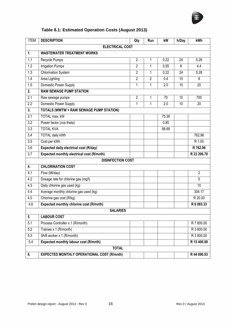
8.2 Estimated Operation Costs
The following table shows the estimated monthly operational cost, which includes electrical, chemical and staff salary costs. With reference to the GIBB report “Process Selection Options” (dated June 2012), the daily power consumption for an activated sludge plant (3-stage Phoredox process) is roughly 40% greater than that of the proposed pond system.
Prelim design report - August 2013 - Rev 0 16 Rev 0 / August 2013
Table 8.1: Estimated Operation Costs (August 2013)
ITEM DESCRIPTION Qty Run kW h/Day kWh
ELECTRICAL COST
1. WASTEWATER TREATMENT WORKS
1.1 Recycle Pumps 2 1 0.22 24 5.28
1.2 Irrigation Pumps 2 1 0.55 8 4.4
1.3 Chlorination System 2 1 0.22 24 5.28
1.4 Area Lighting 2 2 0.4 10 8
1.5 Domestic Power Supply 1 1 2.0 10 20
2. RAW SEWAGE PUMP STATION
2.1 Raw sewage pumps 2 1 70 10 700
2.2 Domestic Power Supply 1 1 2.0 10 20
3. TOTALS (WWTW + RAW SEWAGE PUMP STATION)
3.1 TOTAL max. kW 75.39
3.2 Power factor (cos theta) 0.85
3.3 TOTAL KVA 88.69
3.4 TOTAL daily kWh 762.96
3.5 Cost per kWh R 1.00
3.6 Expected daily electrical cost (R/day) R 762.96
3.7 Expected monthly electrical cost (R/mnth) R 23 206.70
DISINFECTION COST
4. CHLORINATION COST
4.1 Flow (Ml/day) 2
4.2 Dosage rate for chlorine gas (mg/l) 5
4.3 Daily chlorine gas used (kg) 10
4.4 Average monthly chlorine gas used (kg) 304.17
4.5 Chlorine gas cost (R/kg) R 20.00
4.6 Expected monthly chlorine cost (R/mnth) R 6 083.33
SALARIES
5. LABOUR COST
5.1 Process Controller x 1 (R/month) R 7 800.00
5.2 Trainee x 1 (R/month) R 3 800.00
5.3 Shift worker x 1 (R/month) R 3 800.00
5.4 Expected monthly labour cost (R/mnth) R 15 400.00
TOTAL
6. EXPECTED MONTHLY OPERATIONAL COST (R/mnth) R 44 690.03

Prelim design report - August 2013 - Rev 0 17 Rev 0 / August 2013
APPENDIX A
Peddie WWTW Process Flow Diagram


11
4.3 APPENDIX C3 – Proposed WWTW Design Layout Plan

12
4.4 APPENDIX C4 - Site Selection Options

East London Office GIBB House, 9 Pearce Street, Berea, 5241 Tel: +27 43 706 3600 Fax: +27 43 706 3658 www.gibb.co.za
Peddie Wastewater Treatment Works
Peddie Wastewater Treatment Works Upgrade
Preliminary Assessment of Proposed Sites for the Construction of a Pond
System
Peddie Wastewater Treatment Works
Preliminary Assessment of Proposed Sites for the Construction of a Pond
June 2013 J25116B

Report on Peddie WWTW ponds sites Rev 0 / June 2013
PEDDIE WASTEWATER TREATMENT WORKS UPGRADE
PRELIMINARY ASSESSMENT OF PROPOSED SITES FOR THE
CONSTRUCTION OF A POND SYSTEM
CONTENTS
Chapter Description Page
1 INTRODUCTION 1
2 METHODOLOGY AND ASSUMPTIONS 3
3 PROPOSED SITES 4
3.1 Site 1 4
3.2 Site 2 5
3.3 Site 3 6
3.4 Site 4 8
4 CONCLUSIONS AND RECOMMENDATIONS 9
4.1 Conclusions 9
4.2 Recommendations 9
APPENDICES Appendix A : Figure 1 - Layout Plan Appendix B : Deeds Office Data Appendix C : Local Spatial Development Framework Plan

Report on Peddie WWTW ponds sites 1 Rev 0 / June 2013
1 INTRODUCTION
GIBB was appointed by the Ngqushwa Municipality on 13 March 2003 for the provision of professional services relating to the upgrading of bulk sanitation. The project was then transferred from the local municipality to Amathole District Municipality (ADM) on 02 November 2004. The project became dormant (owing to funding issues) until a revised appointment was issued on 02 December 2010. A Project Inception Meeting was held in January 2012. This was followed by a Technical Workshop on 10 April 2012, at which input was obtained from the operation and maintenance team, and design aspects such as treatment process options were discussed. GIBB was tasked with the preparation of a Preliminary Design Report in which the various process options and associated lifecycle costs were discussed. The proposed treatment process options presented included :
• Waste Stabilisation Ponds • PETRO Process • Activated Sludge (AS) • Sequencing Batch Reactor (SBR) • Package Plant Upgrade • Membrane Bio-Reactor (MBR)
Subsequent to this report, a Process Selection Options Report was required. This was submitted to ADM on 4 June 2012. At a meeting held on 18 October 2012 GIBB was requested to submit a further report on pond-only options, for further consideration by ADM. The reasons which had led ADM to viewing a pond system as more favourable than other treatment options included the fact that :
• Aerators in activated sludge plants consume vast amounts of energy • Operation and maintenance of ponds is somewhat simpler, which is
necessary in areas such as Peddie, where it is difficult to find and retain skilled staff
• A pond system is more forgiving when problems occur within the plant, allowing more time to resolve issues such as breakdowns
Following on from this report and the necessary ADM internal processes, a Progress Meeting was held on 15 April 2013. GIBB presented a summary of the pond-only options as follows :
• An area of 18.5 ha would be required for a 2 Mℓ/day plant • The general effluent standards can be met

Report on Peddie WWTW ponds sites 2 Rev 0 / June 2013
• The system would comprise : o head of works o upflow anaerobic sludge blanket reactor o primary aerobic pond o four secondary aerobic ponds o aquatic pond o anaerobic digestion pond o sludge drying beds
At this meeting it was suggested that a pump station be constructed on the site currently occupied by the package plant, and it was recommended that an inlet works be constructed ahead of the pump station, to condition the sewage before it is pumped to the proposed pond system. At the conclusion of the meeting it was decided that potential pond sites would be investigated using Google Earth and topographical maps, followed by a site visit. Land issues pertaining to the proposed sites were to be investigated – including matters such as ownership, zoning, alignment with the municipality’s Spatial Development Plan, as well as the existence of any potential land claims.

Report on Peddie WWTW ponds sites 3 Rev 0 / June 2013
2 METHODOLOGY AND ASSUMPTIONS
Possible sites were identified using Google Earth software. Following on from this, a site visit was conducted on 22 May 2013. Additional potential sites were identified whilst on site. An image indicating the general area is presented in Figure 1.
Figure 1 : Google Earth image indicating general locality
Subsequent to the site visit, a layout drawing was prepared on which 18.5 ha plots were demarcated on the potential sites, to confirm whether the proposed pond system could be accommodated on those sites. Refer to Figure 1 in Appendix A for the layout plan. Based on this layout, an investigation into land ownership as well as compatibility with the Peddie Local Spatial Development Framework Plan (LSDFP) was conducted. It was also necessary to investigate the possibility of any land claims having been lodged in respect of the identified properties. No geotechnical or geohydrological investigation has been conducted and no survey has been undertaken on these potential sites. It must be noted that the sewage treatment ponds site and associated buffer indicated on the LSDFP were based on input from others from a previous study – this was not based on the GIBB investigation.

Report on Peddie WWTW ponds sites 4 Rev 0 / June 2013
3 PROPOSED SITES
3.1 Site 1
3.1.1 Site Description
This land lies to the immediate west of the existing effluent ponds at the Nompumelelo Hospital Complex, and includes a portion of land within the confines of the hospital fence line. The land has an average slope of 1:15.
Plate 1 : Proposed Site 1
3.1.2 Deed Data
The proposed site straddles properties Erf 54, Erf 93, and Farm 77. Erf 54 and Erf 93 are registered to the Local Municipality of Ngqushwa. Farm 77 seems to be unregistered, which implies that this is State land. Farm 77 should therefore be avoided. Refer to Appendix B for copies of the Deeds Office data.
3.1.3 Local Spatial Development Framework Plan A required river buffer is indicated towards the north of this site. This area would have to be avoided in accordance with environmental requirements. The site lies beyond the indicated urban edge. Refer to Appendix C for a copy of the Local Spatial Development Framework Plan.
Existing effluent ponds
Nompumelelo Hospital Complex Proposed
Site 1

Report on Peddie WWTW ponds sites 5 Rev 0 / June 2013
3.1.4 Land Claims Confirmation of land claims on the properties is currently being sought from the office of the Land Claims Commissioner.
3.1.5 Suitability of Site This site seems suitable in terms of grade – there is a constant slope of approximately 1:15 across the land. The site is accessible from the hospital access road. The rising main from the proposed pump station (at the site of the existing package plant) would require a road crossing under the N2. Discussion with the Department of Health will be required, as a portion of the proposed site lies within the Nompumelelo Hospital grounds.
3.2 Site 2
3.2.1 Site Description
This site lies to the west of the existing (defunct) effluent ponds, and south west of the Nompumelelo Hospital Complex.
Plate 2 : Proposed Site 2
Existing effluent ponds
Proposed Site 2

Report on Peddie WWTW ponds sites 6 Rev 0 / June 2013
3.2.2 Deed Data The proposed site straddles properties Erf 54, Erf 93, and Farm 77. Erf 54 and Erf 93 are registered to the Local Municipality of Ngqushwa. Farm 77 seems to be unregistered, which implies that this is State land. Farm 77 should therefore be avoided. Refer to Appendix B for copies of the Deeds Office data.
3.2.3 Local Spatial Development Framework Plan The site lies beyond the indicated urban edge. Refer to Appendix C for a copy of the Local Spatial Development Framework Plan.
3.2.4 Land Claims Confirmation of land claims on the properties is currently being sought from the office of the Land Claims Commissioner.
3.2.5 Suitability of Site The land is confined by the hospital access road to the north, the hospital complex to the north east and a natural watercourse to the south west. Owing to these restrictions, the available land is smaller in area than the required 18.5 ha. This site is somewhat steeper than Site 1. Access is possible from the hospital access road. The rising main from the proposed pump station (at the site of the existing package plant) would require a road crossing under the N2.
3.3 Site 3
3.3.1 Site Description
This site lies to the west of the N2, approximately 2.2 km from the intersection of the N2 and the R345. A portion of the area is somewhat disturbed, as it has been used as a spoil site for the construction activities associated with the N2 upgrade project.

Report on Peddie WWTW ponds sites 7 Rev 0 / June 2013
Plate 3 : Proposed Site 3
3.3.2 Deed Data
The proposed site straddles properties Erf 54 and Erf 93. Both erven are registered to the Local Municipality of Ngqushwa. Refer to Appendix B for copies of the Deeds Office data.
3.3.3 Local Spatial Development Framework Plan The site lies beyond the indicated urban edge. Refer to Appendix C for a copy of the Local Spatial Development Framework Plan.
3.3.4 Land Claims Confirmation of land claims on the properties is currently being sought from the office of the Land Claims Commissioner.
3.3.5 Suitability of Site This site seems suitable in terms of general slope, however, it lies on the watershed between two catchment areas. This may prove costly in terms of the earthworks required to achieve the necessary hydraulic levels for the pond system. The rising main from the proposed pump station (at the site of the existing package plant) would be approximately 1.8 km, and would not require a road crossing under the N2.

Report on Peddie WWTW ponds sites 8 Rev 0 / June 2013
The site could be accessed from the N2 (if permitted) or from an existing gravel road which passes the site.
There is a watercourse nearby into which final effluent could be discharged.
3.4 Site 4
3.4.1 Site Description
This southernmost site lies to the west of the N2, approximately 2.8 km from the intersection of the N2 and R345. The land is highly undulated. No photograph was taken of this site.
3.4.2 Deed Data The proposed site straddles properties Erf 54 and Erf 93. Both erven are registered to the Local Municipality of Ngqushwa. Refer to Appendix B for copies of the Deeds Office data.
3.4.3 Local Spatial Development Framework Plan The site lies beyond the indicated urban edge. Refer to Appendix C for a copy of the Local Spatial Development Framework Plan.
3.4.4 Land Claims Confirmation of land claims on the properties is currently being sought from the office of the Land Claims Commissioner.
3.4.5 Suitability of Site The site is highly undulated, which would require extensive earthworks in order to construct ponds. This site is also the furthest from the proposed pump station (at the site of the existing package plant), leading to a rising main of approximately 2 km. A road crossing under the N2 would not be required. The site could be accessed from the N2 (if permitted) or from an existing gravel road which passes the site. As with Site 3, there is a watercourse nearby into which final effluent could be discharged.

Report on Peddie WWTW ponds sites 9 Rev 0 / June 2013
4 CONCLUSIONS AND RECOMMENDATIONS
4.1 Conclusions
GIBB has undertaken a desktop study and site visit to identify potential sites for the location of a new sewage pond system for Peddie. Four sites were identified and investigated. The sites effectively lie on three erven - Erf 54, Erf 93 and Farm 77. Erf 54 and Erf 93 are registered to the Local Municipality of Ngqushwa. Farm 77 is State land, and as such, must be avoided. This is easily done, as the boundaries of proposed Site 1 and Site 2 can be slightly realigned to avoid this land.
The Local Spatial Development Framework Plan does not indicate a clash with the proposed land use. The proposed sites lie beyond the urban edge. Presently there are no regulations governing a prescribed buffer zone around wastewater treatment works. This is currently under review by Department of Water Affairs. Town Planners insert a 500 m buffer around wastewater treatment works as a standard, but a legal requirement for such could not be confirmed. At this stage, no information on potential land claims has been obtained – GIBB is waiting for a response from the office of the Land Claims Commissioner. We have been advised that this may take some time to investigate. Based on the above considerations, it would seem that Site 1 would be the most appropriate choice for the location of a new effluent pond system, followed by Site 3. Site 2 is not sufficiently large to accommodate the ponds, while Site 4 would entail significantly greater earthworks than the other sites.
4.2 Recommendations
It is recommended that Site 1 and Site 3 be further investigated in order to finalise the choice of site for the location of the ponds. The following processes should be undertaken next :
1. Liaise with the Department of Health and the Ngqushwa Local Municipality regarding the land within the Nompumelelo Hospital Complex fence line.
2. Confirm that there are no land claims lodged against those properties on which Site 1 and Site 3 lie.
3. Undertake a geotechnical investigation on both Site 1 and Site 3 in order to confirm the suitability of the ground properties and founding conditions for the construction of a pond system.
4. Survey the site which is finally chosen for the location of the ponds.

Report on Peddie WWTW ponds sites Rev 0 / June 2013
APPENDICES

Report on Peddie WWTW ponds sites Rev 0 / June 2013
APPENDIX A
Figure 1 : Layout Plan
Report on Peddie WWTW ponds sites Rev 0 / June 2013
APPENDIX B
Deeds Office Data

Report on Peddie WWTW ponds sites Rev 0 / June 2013
APPENDIX C
Local Spatial Development Framework Plan

Rev 0 / June 2013
DOCUMENT CONTROL FORM IP180_B CLIENT : Amathole District Municipality
PROJECT NAME : Peddie Wastewater Treatment Works Upgrade
PROJECT No. : J25116B
TITLE OF DOCUMENT : Preliminary Assessment of Proposed Sites for the Construction of a Pond System
ELECTRONIC LOCATION :
P:\J25116B_Peddie Sewerage Treatment Works B\3-Tasks\Reports\Report on Peddie WWTW ponds sites.docx
Approved By Reviewed By Prepared By
ORIGINAL NAME Dave Clark
NAME Victor de Wet
NAME Sharnae Hopewell
DATE 21 June 2013
SIGNATURE
SIGNATURE
SIGNATURE
Prepared by Prepared By Prepared By
REVISION NAME
NAME
NAME
DATE
SIGNATURE
SIGNATURE
SIGNATURE
Approved By Reviewed By Prepared By
REVISION NAME
NAME
NAME
DATE
SIGNATURE
SIGNATURE
SIGNATURE
This report, and information or advice, which it contains, is provided by GIBB (or any of its related entities) solely for internal use and reliance by its Client in performance of GIBB’s duties and liabilities under its contract with the Client. Any advice, opinions, or recommendations within this report should be read and relied upon only in the context of the report as a whole. The advice and opinions in this report are based upon the information made available to GIBB at the date of this report and on current South African standards, codes, technology and construction practices as at the date of this report. Following final delivery of this report to the Client, GIBB will have no further obligations or duty to advise the Client on any matters, including development affecting the information or advice provided in this report. This report has been prepared by GIBB in their professional capacity as Consulting Engineers. The contents of the report do not, in any way, purport to include any manner of legal advice or opinion. This report is prepared in accordance with the terms and conditions of the GIBB contract with the Client. Regard should be had to those terms and conditions when considering and/or placing any reliance on this report. Should the Client wish to release this report to a Third Party for that party's reliance, GIBB may, at its discretion, agree to such release provided that: (a) GIBB’s written agreement is obtained prior to such release, and (b) By release of the report to the Third Party, that Third Party does not acquire any rights, contractual or otherwise, whatsoever
against GIBB and GIBB, accordingly, assume no duties, liabilities or obligations to that Third Party, and (c) GIBB accepts no responsibility for any loss or damage incurred by the Client or for any conflict of GIBB interests arising out of
the Client's release of this report to the Third Party. GIBB (Pty) Ltd Website : www.gibb.co.za
Postal Address : PO Box 19844, Tecoma, 5214
Physical Address : GIBB House, 9 Pearce Street, Berea, 5241
Contact Person : Victor de Wet Email Address : [email protected]
Telephone No. : +27 43 706 3600 Fax No. : +27 43 706 3658

13
5 APPENDIX D – SPECIALIST REPORTS
No Specialist Reports

14
6 APPENDIX E: COMMENTS AND RESPONSE

COMMENTS AND RESPONSE: PROPOSED NEW 2ML POND ONLY WWTW FOR PEDDIE
COMMENT DATE PERSON ORGANISATION/FARM NO/PROPERTY NO COMMENTS RESPONSE
COMMENTS RECEIVED DURING THE COMMENTS PERIOD 21 March – 11 June 2014
1
24/03/2014 Mr. Landile Jack Department of Water Affairs
1.1 Hi Lizna, Please list your office as an IAP on this project then put it through the normal channels for comments.
1.1 DAW was registered as I&AP’s for this project. No comments were received from DWA.
2
17/04/14 Mr. S Mnweba Ngqushwa Municipality 2.1 Kindly be informed that the Ngqushwa Municipality has read the report and supports Site A of the proposed sites. The Municipality is of the opinion that Site B is prime land and can be used for future housing development. Site A is preferred because of the gravity (is at the lowest contour and the flow will be downslope).
2.1 Noted, the EAP has recommended that Site A be used for the proposed project.
2.2 The following should be noted in the vicinity of Site A. The Municipality has subdivided a portion for Eskom along the gravel road; therefore there is a need of working together with Municipality in terms of the size and buffer zone of the pond. The exact size of the pond needs to be determined.
2.2 Noted, the engineers have been made aware of the portion of land required by Eskom and will amend the site plan for Site A accordingly.
3
09/06/2014 Mr. Landile Jack Department of Water Affairs 3.1 Hi Loni, Please do you remember if comments were prepared and sent on the attached proposal? I was called this morning by Cedric of Indwe; his office has not received comments from Water Affairs. Please assist. If comments were not sent. I will ask Mmabatho to draft a letter for your attention.
3.1 Noted, No comments have been received from DWA.

COMMENT DATE PERSON ORGANISATION/FARM NO/PROPERTY NO COMMENTS RESPONSE
COMMENTS RECEIVED DURING THE COMMENTS PERIOD 21 March – 11 June 2014
4 10/06/2014 Mr. Mlamli Mabulu
Department of Health, Bhisho 4.1 Hi Cedric, The environmental section has promised to visit the site next week Tuesday. I believe they will make arrangements with you. The comments will come after. Babongile deals with the project.
4.1 Noted,
5 11/06/2014 Mrs J Gouws South African National Roads Agency Limited 5.1 Your background Information document emailed to SANRAL on 24 March refers. This letter serves to confirm SANRAL as an interested and affected party (I&AP) and to convey our initial comments on the proposed waste water treatment works. SANRAL’s comments are as follows:
5.1 Noted, SANRAL have been registered as I&AP’s for this project.
5.2 SANRAL is in the process of implementing road improvements on the affected section of National Route N2. These improvements include the widening of the road reserve, and the widening of the road carriageway itself.
5.2 Noted
5.3 Detailed layouts of Sites A and B would be required in order for SANRAL to give full comments with particular reference to the proposed accesses. Indicative traffic movements into and out of the treatment works would be required.
5.3 A copy of the draft Basic Assessment Report will be sent to SANRAL for comment. The dBAR has detailed layout plans which show proposed access routes.
5.4 It would appear that Site A could be accessed from the R345, but a proposed access onto the N2 is anticipated. Details would be required so that SANRAL can assess the safety aspects and the risk to the integrity of the N2 via inter alia turning traffic, chemical spillage and erosion.
5.4 The use of Site A for the construction of the new WWTW has been recommended by the EAP in the dBAR. Access to the proposed Site A would be via the existing R345 gravel road to the Nompumelelo Hospital Complex.
5.5 Site B would be challenging in terms of direct access from the N2. It is located on the inside of a curve and therefore sight distance would be compromised. Details on any proposed access are required for.
5.5 The use of Site A for the construction of the new WWTW has been recommended by the EAP thereby rendering Site B as null and void.

COMMENT DATE PERSON ORGANISATION/FARM NO/PROPERTY NO COMMENTS RESPONSE
COMMENTS RECEIVED DURING THE COMMENTS PERIOD 21 March – 11 June 2014
5.6 It should be noted that direct access onto the N2 could be ruled out for safety reasons. The geometry of the road and the surrounding topography will dictate.
5.6 As above
5.7 No advertising or other signage associated with the waste water treatment works shall be displayed to be visible from the national road N2. Prospective contractors for the construction of the Works will need to be advised accordingly. All advertising shall comply with the requirements of the SANRAL Act, the Regulations on Outdoor Advertising and the South African Road Signs Manual. Such advertisement proposals must be submitted to SANRAL for considering and approval.
5.7 Noted, the consulting engineers will be made aware of these requirements.
COMMENT DATE PERSON ORGANISATION/FARM NO/PROPERTY NO COMMENTS RESPONSE
COMMENTS RECEIVED DURING REVIEW OF DRAFT BASIC ASSESSMENT COMMENTS PERIOD

COMMENT DATE PERSON ORGANISATION/FARM NO/PROPERTY NO COMMENTS RESPONSE
COMMENTS RECEIVED DURING REVIEW OF DRAFT BASIC ASSESSMENT COMMENTS PERIOD

COMMENT DATE PERSON ORGANISATION/FARM NO/PROPERTY NO COMMENTS RESPONSE
COMMENTS RECEIVED DURING REVIEW OF DRAFT BASIC ASSESSMENT COMMENTS PERIOD

15
7 APPENDIX F: ENVIRONMENTAL MANAGEMENT PROGRAMME

____________________________________________________________________________________
____________________________________________________________________________________
DRAFT ENVIRONMENTAL MANAGEMENT PROGRAMME FOR THE PROPOSED NEW 2ML POND ONLY WASTE WATER TREATMENT WORKS TO SERVICE THE TOWN OF PEDDIE, NGQUSHWA LOCAL MUNICIPALITY, EASTERN CAPE.
Prepared in support of an application for Environmental Authorisation in terms of the June 2010 EIA Regulations published under Section 24(5) of the National Environmental Management Act, Act 107 of 1998
June 2014 – J2011-24
______________________________________________________________________________________
• Indwe Environmental Consulting CC • 12 Preston Avenue • Vincent • East London • 5247 • • Tel: 043 726 6860 • Cell: 083 766 7514 • Fax: 086 513 9734 • Email: [email protected] •
• Company Registration No.: 2006/074394/23 •

Peddie 2ML WWTW - EMP June 2014 1
NEW PEDDIE 2ML WASTE WATER TREATMENT WORKS ENVIRONMENTAL MANAGEMENT PROGRAMME
CONTENTS
Chapter Description Page
1 INTRODUCTION 3
1.1 Background Information 3
1.2 Nature and Structure of this Report 3
1.3 General Environmental Principles 4
1.4 EMP Version 5
2 DESCRIPTION OF ACTIVITY 6
2.1 Description of Proposed Activity 6
3 ROLES AND RESPONSIBILITIES 7
3.1 The Proponent – O R Tambo District Municipality 7
3.2 The Environmental Control Officer 7
3.3 The Consulting Engineer (GIBB Consulting Engineers) 8
3.4 The Contractor 8
3.5 Communication between Parties 9
4 ENVIRONMENTAL SPECIFICATIONS – CONSTRUCTION PHASE 10
4.1 Administration 10
4.2 Site Demarcation 10
4.3 Work Site Preparation 12
4.4 Clearing of Indigenous Vegetation 12
4.5 Clearing of Topsoil 13
4.6 Stockpiling of Topsoil 14
4.7 Building Material 15
4.8 Borrow Pits 15
4.9 Spoil Sites 15
Peddie 2ML WWTW - EMP June 2014 2
4.10 Open Trench Length 16
4.11 Reinstatement of Trenches 16
4.12 Construction Activities in and around Wetlands and Watercourses 17
4.13 Overhead Power Lines 17
4.14 Public Protection 18
4.15 Social Disruption 18
4.16 Existing Services 18
4.17 Construction Vehicles and Access Roads 18
4.18 Noise Control 19
4.19 Dust Control 19
4.20 Erosion Prevention 19
4.21 Waste Management 20
4.22 Material Use, Handling and Transport 21
4.23 Servicing of Equipment 22
4.24 Alien Vegetation Management 22
4.25 Rehabilitation of Working Areas 23
4.26 Fire Prevention and Control 25
4.27 Heritage Resources 26
5 COMPLIANCE 27
5.1 Work Stoppage 27
5.3 Amendments 27
5.4 Training 27
5.5 Monitoring and Auditing 27
6 METHOD STATEMENTS 29
6.1 Requirements of a Method Statement 29
6.2 Example of a Method Statement 29

Peddie 2ML WWTW - EMP June 2014 3
1 INTRODUCTION
1.1 Background Information
Indwe Environmental Consulting CC was appointed by GIBB as an independent Environmental Assessment Practitioner (EAP) to undertake a Basic Environmental Assessment (BA) as well as prepare an Environmental Management Programme (EMP) for the proposed construction of a new 2ML Pond Only Waste Water Treatment Works to service the Town of Peddie, Ngqushwa Local Municipality, Eastern Cape.
In order to minimise any environmental damage on site, an Environmental Management Programme is required for the Planning and Design Phase, Construction Phase and Operational Phase of the project. The EMP also includes specifications for Rehabilitation aspects. This EMP provides details of the project components and activities outlined in the Basic Assessment Report, the roles and responsibilities of all parties with respect to Environmental Management during construction and Environmental Specification that must be enforced on site. The BA and EMP conform to the June 2010 EIA Regulations as promulgated in terms of the National Environmental Management Act (Act 107 of 1998), as amended.
1.2 Nature and Structure of this Report
This report fulfils the requirement of the EIA Regulations (2010) that require an EMP to include:
Details and expertise of the person who prepared the Environmental Management Programme.
A detailed description of the aspects of the activity that are covered by the Environmental Management Programme.
Information on any proposed management or mitigation measures that will be implemented to address the environmental impacts and issues that have been identified in a report required by the Regulations, including environmental impacts and issues in terms of:
o Planning and design (where relevant); o Pre-construction and construction activities; o Operation or undertaking of the activity; o Rehabilitation of the environment; and o Closure (where relevant).
An identification of the persons who will be responsible for the implementation of the proposed management or mitigation measures referred to above.

Peddie 2ML WWTW - EMP June 2014 4
Where appropriate, time periods within which the proposed management or mitigation measures must be implemented.
The proposed mechanisms for monitoring compliance with the Environmental Management Programme and reporting thereon.
1.3 General Environmental Principles
The following principles should be considered at all times during planning and implementation of this phase of the project:
The Environment is considered to be composed of both biophysical and social components.
Construction and excavation are disruptive activities and due consideration must be given to the environment, including the social environment, during the execution of a project to minimise the impact on affected parties.
Minimisation of areas disturbed by construction and excavation activities (i.e. the footprint of the construction and excavation areas) should minimise many of the related environmental impacts of the project and reduce rehabilitation requirements and costs.
As minimum requirements, all relevant standards relating to international, national, provincial and local legislation, as applicable, shall be adhered to. This includes the following legislation which can, inter alia, have an effect on construction activities or the environment. This list is not necessarily complete and the onus shall remain on the Contractor to ensure that all relevant legislation is conformed with.
Environmental Conservation Act, No 73 of 1989. Particularly Sections 19, 19A, 20, 21, 22 and 31A. Also all relevant Government Notices issued under this Act, especially GN 1182, GN 1183 and GN 1184.
The regulations in terms of the National Environmental Management Act (No.107 of 1998) (GN 543 -546 dated 18 June 2010) are particularly relevant.
National Forest Act, (Act 84 of 1998)
National Water Act (Act 36 of 1998)
Provincial Nature Conservation Ordinances.
Minerals and Petroleum Resources Development Act (28 of 2002)
Conservation of Agricultural Resources Act (Act 43 of 1983).
Atmospheric Pollution Prevention Act, No 45 of 1965.
Occupational Health & Safety Act, No.85 of 1993.
Every effort should be made to minimise, reclaim and/or recycle “waste” material.
The Environment is held in public trust for the benefit of people, due care must therefore be exercised to ensure that the rights of others with respect to its use are respected.
This requires that a risk averse and cautious approach to the management of activities associated with the project be adopted at all times. The EMP provides specifications that all parties shall adhere to, in order to minimise adverse environmental impacts and optimise opportunities associated with construction activities.

Peddie 2ML WWTW - EMP June 2014 5
In the event of discrepancy with part or parts of the standard specifications or project specifications, this section shall take precedence.
1.4 EMP Version
This is the first version of the Environmental Management Programme. This EMP should be treated as a dynamic document which is updated timeously as new project information becomes available. As a minimum, the EMP must be updated to include the conditions of Environmental Authorisation as well as any other permit conditions associated with other environmental approvals, e.g. Water Use Licences, etc.

Peddie 2ML WWTW - EMP June 2014 6
2 DESCRIPTION OF ACTIVITY
2.1 Description of Proposed Activity
Project Description It is the intention of Amathole District Municipality to decommission the existing extended aeration sewage treatment plant and to replace it with a pond only waste water treatment works which will be located at an alternative site. The proposed treatment process will be a combination between an Up-flow Anaerobic Sludge Blanket Reactor, a Facultative-Aerobic Pond System and a Floating Aquatic Pond. The proposed WWTW will have a treatment capacity of 2 000 kℓ/day ADWF and an average daily organic load of 2 268 kg COD/day and will consist of the following unit process components: Pump Station A pump station will be constructed on the site currently occupied by the existing sewage treatment plant. Once sewage has passed through the inlet works it will be pumped to the proposed pond system. Primary Treatment
a) Inlet works ahead of pump station for the conditioning of sewage (including screening, de-gritting and inflow measurement)
b) Two up-flow anaerobic sludge blanket reactors Secondary Treatment
a) One primary facultative pond with a total surface area of 25 000m2 and a depth of 1.2m b) One secondary facultative pond with a total surface area of 16 667m2 and a depth of 1.2m c) Three tertiary facultative ponds with a total surface area of 8 333m2/pond and a depth of
1.2m/pond Tertiary Treatment
a) One floating aquatic pond with a total surface area of 39 920m2 and a depth of 1.8m b) Disinfection of the final effluent via a chlorine contact tank with a tank volume of 90m2
Sludge Handling
a) One anaerobic sludge reactor with a total surface area of 857m2 and a depth of 3.5m b) Four sludge drying beds with a surface area of 500m2/bed and a depth of 450mm

Peddie 2ML WWTW - EMP June 2014 7
3 ROLES AND RESPONSIBILITIES
The following roles and responsibilities are pertinent.
3.1 The Proponent – Amathole District Municipality
The proponent has ultimate responsibility to ensure the protection of the environment during the construction and rehabilitation phases of the proposed project. The Proponent will be responsible for: 1. Being familiar with the contents of the EMP.
2. Appointment of an Environmental Control Officer (ECO).
3. Appointment of a Consulting Engineer (CE) to oversee the implementation of the works.
4. Making sufficient budget available for implementation of the EMP including a provisional sum for additional environmental protection measures that may be necessary as construction and rehabilitation proceeds.
5. Supporting the Consulting Engineer in enforcing the Environmental Specifications.
6. Communicating with all role players in the interests of a co-ordinated effort to protect the environment.
7. Implement and take responsibility for those specifications relating to the operational phase of the project.
8. Being held liable in the event of non-compliance by any contractor associated with this activity
3.2 The Environmental Control Officer
At commencement of the construction phase, the project proponent must appoint an Environmental Control Officer (ECO). The function of the ECO must be fulfilled by an individual with experience in site based environmental management. The ECO must encourage that, general principles of environmental management applicable to construction activities as well as environmental best practices are adhered to at all times. The ECO will have the following responsibilities at a minimum: 1. To coordinate a briefing session between himself, the consulting engineer and main
contractors on the environmental management programme and associated environmental specifications.
2. To attend regular project team meetings in order to ensure sound environmental planning and implementation.
3. To advise the Consulting Engineer (CE) on the interpretation and enforcement of the Environmental Specifications.
4. To demarcate particular sensitive areas prior to construction activities and pass instructions through the Consulting Engineer concerning works in these areas.
5. To provide on-site environmental guidance, information and approval related to construction activities.

Peddie 2ML WWTW - EMP June 2014 8
6. To undertake regular site inspections to ensure best practise environmental management procedures are applied and to ensure that the specifications as referred to in this Environmental Management Programme are implemented.
7. The ECO should inspect construction activities each month for the duration of the project.
8. The ECO must prepare monthly site inspection reports for distribution to the relevant parties.
9. During construction the ECO must audit the contractor/s on implementation of the specifications of the EMP for the relevant development phase.
10. The ECO must also undertake a detailed post construction compliance audit after completion of each relevant phase.
3.3 The Consulting Engineer (GIBB Consulting Engineers)
The Consulting Engineer (CE) is required to:
1. Be familiar with the contents of the EMP.
2. Monitor the Contractor’s compliance with the Environmental Specifications on a daily basis and enforce compliance.
3. When deemed satisfactory the CE must approve method statements received from contractors describing how work will be undertaken in environmentally sensitive areas.
4. Communicate to the Contractor the advice of the ECO and the contents of the ECO reports and issue site instructions giving effect to the ECO requirements where applicable.
Designate all working areas after seeking advice from the ECO.
Communicate to the ECO any infringements of the Environmental Specifications and accompany the ECO during site inspections.
Discuss with the ECO the application of any penalties and other possible enforcement measures when necessary.
Maintain a record of complaints from the public and communicate these to the ECO.
Facilitate communication between all role-players in the interest of effective Environmental Management.
Monitor the compliance of the Contractor through the ECO reports.
3.4 The Contractor
The Contractor has the responsibility to:
1. Comply with the Environmental Specifications contained in this document.
2. Be familiar with the EMP.
3. Notify the ECO and CE immediately in the event of any accidental infringements of the Environmental Specifications to enable appropriate remedial action to be taken.

Peddie 2ML WWTW - EMP June 2014 9
4. Ensure environmental awareness among their employees and sub-contractors so that they are fully aware of, and understand the Environmental Specifications and the need for them.
5. Undertake rehabilitation of all areas affected by construction activities to restore them to their original states, as determined by the ECO.
6. Undertake the required works within the designated working areas.
7. Prepare method statements and hand them to the CE for approval before undertaking work in environmentally sensitive areas, an example is included in an addendum to this specification.
3.5 Communication between Parties
The importance of open communication between all parties mentioned above is emphasised, as the attainment of environmental quality requires a joint effort. With open communication the role of the ECO should be a positive one - aimed at being proactive in preventing problems - rather than a negative "policing" role when negative impacts have already occurred
Peddie 2ML WWTW - EMP June 2014 10
4 ENVIRONMENTAL SPECIFICATIONS – CONSTRUCTION PHASE
4.1 Administration
The project proponent is to ensure that: 1. All legislation is complied with including permits and licences.
2. An ECO is appointed to oversee the construction phase of the development.
3. That this EMP is made available to the Consulting Engineer, all contractors and that their responsibilities are all understood.
4.2 Site Demarcation
Definitions:
“No Go” areas are often of deep aesthetic, historical and/or environmental value, such as riparian vegetation, indigenous forest/bush or ancestral burial sites.
Working areas are those areas necessary for the contractor to complete the required construction, and should be approved by the ECO and CE.
4.2.1 Working areas and No Go areas
For each construction and pond excavation phase of the project, working areas and “No Go” areas should be clearly demarcated by the ECO and CE in order to avoid further unnecessary disturbance. These areas and any new access tracks are to be clearly defined and demarcated. No construction staff may be permitted access to indigenous bush/grassland outside of the permissible working corridor at any time.
4.2.2 Site Camps and Construction Teams The following general construction guidelines must be adhered to by all contractors and construction teams: 1. Where site camps are to be established the topsoil is to be removed to a depth of 150
mm and stockpiled according to the section on topsoil conservation.
2. The site shall be located more than 100 metres from watercourses and wetlands. Runoff from the site must be prevented from entering any watercourse or wetland in the vicinity of the site camp or work area.
3. Site camps and surrounds are to be maintained in a clean orderly and presentable condition at all times and the limits of the site camp are to be clearly defined at all corners with marker posts of at least 100 mm diameter and not less than 2 metres high (above ground level).
4. The Contractor shall restrict all activities associated within the site camp to within this boundary. Damage to the environment outside of these boundaries will result in a

Peddie 2ML WWTW - EMP June 2014 11
penalty. At the end of the contract, or the removal of facilities from the site, the Contractor shall be responsible for the rehabilitation of the demarcated site.
5. Failure to demarcate any site will result in the Environmental Control Officer defining the area to be rehabilitated at the cost of the contractor.
4.2.3 Kitchen Facilities 1. Construction teams should be provided with sufficient kitchen facilities.
2. Waste water from kitchens facilities shall be led to soak pits and shall not be discharged to rivers or streams.
4.2.4 Sanitation 1. Adequate chemical toilet facilities are to be provided within 200 m of all work sites and at
the site camp. These toilets shall not be located on flood plains where the possibility of flooding exists.
2. Contractors are required to provide separate toilets for male and female workers on site.
3. Contractors shall instruct their staff and sub-contractors that they must use toilets provided and not the veld, bush or streams.
4. All toilets shall be maintained by the Contractor in a clean sanitary condition to the satisfaction of the Engineer and should be serviced regularly as per manufactures specifications.
5. The waste sewage effluent must be disposed of at a registered waste water treatment works and proof of safe disposal certificates are to be presented at each monthly site meeting.
4.2.5 Refuse 1. The site is to be kept clean, neat and tidy to the Engineers satisfaction.
2. The Contractor shall provide bins at the work sites and shall be responsible for disposal of refuse and waste generated by his staff on a daily basis.
3. Domestic litter or construction waste may not be left lying about on site.
4. Refuse and construction waste shall be disposed of at an approved waste disposal sites.
5. No burning of refuse is permitted.
4.2.6 Storage Tanks 1. Tanks for fuels, oils and solvents shall be bunded with earth berms adequate to contain
any possible spills (at least 110 % of the stored volume).
2. It shall be the Contractors responsibility to remove all contaminated earth and dispose of the material to a suitable and approved disposal site and to provide proof of safe disposal.
3. On site storage of fuel may not exceed 23 cubic metres without an Authority from DEDEA.

Peddie 2ML WWTW - EMP June 2014 12
4.2.7 Pouching of Wildlife
1. No fauna shall be disturbed on site or in surrounding forestry/bush areas. Any Contractor’s staff caught interfering with wildlife will face suspension from the project. Criminal charges will be made if poaching is detected.
4.2.8 Indigenous Flora 1. No workers shall be allowed to damage or collect any plants.
4.2.9 Fire 2. The use of indigenous wood for fire making is strictly prohibited.
3. The lighting of fires should be restricted to kitchen areas only.
4.2.10 Site Restoration 1. After completion of the works the Contractor shall restore the area used by him to its
former condition, including removal of rubble and foundations.
2. Any compacted ground shall be ripped to loosen soil. Topsoil is to be spread evenly over the site and grass cover re-established.
4.3 Work Site Preparation
Work site preparation shall be undertaken in accordance with the following parameters: 1. Prior to any construction activities taking place for a particular phase, the contractor
must supply the ECO with a layout plan demarcating the physical extent of the works, the location for the site camp, laydown areas, topsoil stockpile areas, access roads, etc. This plan must be approved by the ECO prior to any clearing taking place.
2. The extent of the works and associated clearing area needed for construction for each phase is to be kept to a minimum.
3. Construction activities, stockpiling of any building material and the storing of machinery must be accommodated within the works area.
4. Any excavated slopes shall be left at a maximum 1:3 (180) gradient or less. It has been found that this is the maximum slope suitable for re-vegetation and rehabilitation purposes.
5. Excavators must follow the contour lines where possible.
4.4 Clearing of Indigenous Vegetation
Every effort must be made to avoid disturbance to indigenous vegetation.
1. No indigenous tree or bush shall be disturbed or removed without approval from the Consulting Engineer who shall discuss removal of natural trees or bush with the Environmental Control Officer.
2. Only vegetation that occurs within the development footprint should be cleared. The clearing of vegetation should be undertaken shortly before construction or excavation activities are to take place.
Peddie 2ML WWTW - EMP June 2014 13
3. Under no circumstances is any indigenous vegetation to be cleared in areas demarcated as No-Go areas.
4.4.1 Removal of Trees 1. Indigenous trees outside of the development footprint may not be removed nor
damaged. It should be noted that no wood or forest products may be transported from site without a valid permit.
2. Soil shall not be piled around the stems of the trees as this can result in attack by termites, which can ringbark and kill the trees.
4.4.2 Specially Protected Plants A number of species and whole families of plants have been declared "Endangered" or "Protected Plants" in terms of the Environmental Conservation Decree No 9 of 1992. It includes Cycads, Tree Ferns, Aloes, Lilies, Orchids and many others. 1. In terms of the ordinance these plants may not be gathered, transported or relocated
without a permit.
2. These plants must therefore be avoided, or if unavoidable, the PECO and Engineer must be consulted timeously so that the necessary approvals for removal and rehabilitation can be obtained.
3. Protected plants, which cannot be avoided, shall be transplanted to a safe position with similar conditions close by.
4. Transplanting shall be done immediately after the plants are unearthed so that the roots do not dry out.
5. Care shall be taken to keep all roots intact when removing these plants and to settle soil firmly around the roots by watering after replanting. Watering will be required until the plants are established and show active growth.
Applicable legislation:
Nature & Environmental Conservation Ordinance, (Ordinance 19 of 1974)
National Forests Act (Act 84 of 1998)
National Environmental Management Biodiversity Act (Act 10 of 2008)
4.5 Clearing of Topsoil
1. During site establishment, topsoil to a depth of 150 mm is to be removed and stockpiled
within development footprints in which the following activities may take place:
Establishment of site camps
All areas to be excavated for pipelines,
Construction vehicles will be parked overnight;
Fuels and other hazardous substances will be stored;
Concrete will be mixed; and
Construction materials will be stockpiled.

Peddie 2ML WWTW - EMP June 2014 14
2. In areas earmarked for pond excavation the topsoil shall be systematically removed and stockpiled. Under no circumstances is blanket topsoil removal to take place at proposed pond sites.
3. All topsoil shall be excavated to the base of the A-horizon or 150 mm whichever is greater, and appropriately stockpiled for later use in rehabilitation. Care must be taken not to mix this topsoil with subsoil and they should be stored separately.
4. Experience has shown that excavator buckets with three teeth are inadequate for separating topsoil and hand labour is preferred for this purpose.
5. All removed topsoil must be stockpiled in such a manner and in such a place that it will not cause damming of water.
6. Where soil will be stockpiled for several months, these stockpiles shall be hand seeded with a suitable rehabilitation mix at the rate of not less than 8 kg/ha before being replaced.
7. All topsoil stockpiles must be protected against wind/soil erosion as well as weeds.
8. Non-woody vegetation such as grasses and forbs should not be removed prior to stripping topsoil from work areas in order to assist in maintaining viability of the soil during storage.
9. Compaction of the topsoil by, inter alia, driving over it is not permitted.
4.6 Stockpiling of Topsoil
1. Topsoil stockpiles should not exceed 3.5 metres in height. 2. Topsoil stockpiles are not to be located within 30 metres of any drainage line, stream or
river.
3. No spoil areas are to be located within any of the No-Go areas.
4. Under no circumstances is stockpiled topsoil to be mixed with any other material (e.g. spoil and building rubble).
5. Any alien invasive species which establish themselves upon stockpiles are to be removed before use in rehabilitation of the site post-construction.
6. If the topsoil stockpile is stored for longer than 8 months, it must be upgraded with seed before being replaced.
7. For each individual topsoil stockpile the most environmentally sound and practically possible method should be employed to prevent soil erosion from taking place i.e. the use of cut off berms, shade cloth or netting etc.
8. All topsoil stockpiles should be dampened during dry conditions in order to prevent excessive dust.
9. Once construction activities have been completed in areas in which topsoil was removed. The stockpiled soil should be immediately replaced and used for the rehabilitation of the site if needed.
10. Alien invasive species which colonize disturbed ground must be systematically removed and destroyed prior to it attaining the seed formation stage. This vegetation must be disposed of in a permitted landfill site.
11. Grass and forbs should not be removed prior to stripping of the topsoil.

Peddie 2ML WWTW - EMP June 2014 15
12. No driving of vehicles or heavy plant on topsoil stockpiles is permitted.
4.7 Building Material
1. All gravel, sand and stone used during construction must be obtained from a bona fide
source.
2. No fill material is to be brought on site. Excess material remaining after each phase of construction, is to be removed from the site and disposed of at a registered waste disposal site.
4.8 Borrow Pits
1. Borrow pits shall only be developed after approval from the Department of Mineral and
Energy Affairs.
2. The Contractor shall advise the Engineer at least 10 days in advance of his intention to open up each borrow pit.
3. For the purposes of controlling materials used on site and preventing supply from un-licenced sites, contractors are required to declare their sources of material supply and provide proof that these suppliers are registered with DME.
4. For each borrow pit the topsoil shall be removed, stockpiled and maintained for later replacement according to specifications given for topsoil conservation.
5. The operation of borrow pits shall be conducted such that runoff is prevented from entering streams, and slumping of soil from the hillside above the excavation cannot occur.
6. The operation shall also be conducted in such a way as to minimise the amount of earthmoving required to rehabilitate to a condition resembling the contours of the original landscape.
7. The Engineer will determine what environmental protection or rehabilitation measures will be necessary in each case.
8. Rehabilitation measures will be aimed at: managing runoff to prevent erosion, restoring the site aesthetically so that it blends with surroundings, and restoring adequate soil and vegetation cover to achieve these objectives. The site specific EMP for the licenced borrow pit will direct this rehabilitation.
4.9 Spoil Sites
1. Spoiling of soil and rock shall not be permitted along drainage lines except that blast rock
or boulders may be used to heal dongas with prior approval of the ECO.
2. In some cases existing erosion gullies or dongas in the landscape may be used for spoiling of rock (100 – 500 mm diameter) in order to arrest erosion.
3. Choice of such sites shall be at the discretion of the Engineer in consultation with the ECO and spoiling shall be conducted in a manner specified by the Engineer.
4. Erosion gullies are suitable for spoiling rock only, and not soil, as soil will be washed out. Access to such spoil sites must not be permitted to lead to further erosion.
Peddie 2ML WWTW - EMP June 2014 16
4.10 Open Trench Length
1. Unless otherwise permitted in writing by the Engineer, not more than 500 m of trench
per pipe laying gang shall be open at any time. This length implies that opening, pipe laying and closure take place within the 500 m work area.
2. Open trench” includes the period from initial removal of topsoil to replacement of topsoil after backfilling.
3. Following installation, the testing of pipelines and backfilling of trenches (including topsoil) shall be completed for each section of pipeline without delay. The reason for this is to minimise the negative impacts associated with open trenches and maximise the likelihood that grass contained in topsoil will regrow.
4. Any work that is authorised to take place through wetlands and streams shall not commence until the Contractor confirms that all the material is on site and that work can commence and be completed with the available material.
5. Once work begins in these areas (wetland or stream) open trench time shall not exceed 14 days from the start date to rehabilitation unless a full motivation is submitted within the 14 day construction period, and that the delay relates to construction issues and not material or equipment.
6. Failure to complete work in sensitive areas within the allocated time will result in daily penalties until the work is completed.
4.10.1 Open Trench Protection 1. Adequate measures must be taken to prevent humans or stock from injuring themselves
by falling into an open trench adjacent to public access ways.
4.11 Reinstatement of Trenches
1. The topsoil shall be replaced on top after backfilling and only lightly compacted (e.g. by
trampling under foot).
2. Where grass seeding is required it must be carried out on the same day as topsoil replacement and before lightly compacting the soil.
3. Care shall be taken to ensure that the finished surface is not below the surrounding ground to avoid channelling or concentrating flows.
4. Where slope gradients exceed 12% in long-section, anti-erosion berms shall be made which are angled across the contours so that they lead the water off the disturbed corridor.
5. These berms shall be at least 300 mm high and shall be long enough to lead water off the entire disturbed surface.
6. The ridges shall be at a maximum spacing which is the lesser of 30 m horizontal distance or 1 m vertical distance.
7. No additional payment shall be made for anti-erosion measures. If a specification for cross-fall berms has been provided by the Engineer then the engineering specification takes precedence.

Peddie 2ML WWTW - EMP June 2014 17
8. These berms shall be made immediately after backfilling and before topsoil replacement and berms shall not be made of, or contain, large rocks.
4.12 Construction Activities in and around Wetlands and Watercourses
1. No work shall take place in or within 50m of any wetland area.
2. A No-Go buffer zone of 50m around wetland areas must be maintained at all times.
3. The crossing of any stream bed, flowing stream or river requires a license from Department of Water Affairs.
4. The Consulting Engineer shall be responsible for obtaining such approvals prior to any work commencing on site.
5. Work within watercourses should be completed timeously and preferably be undertaken when water levels are low.
6. No structure placed in the bed of any water course shall obstruct the flow of the river after construction is complete and pipeline crossings are to be placed below the river bed.
7. The top of pipe (or encasement) shall be rehabilitated to resemble the surrounding bed conditions.
8. The Consulting Engineer is responsible for selection of a suitable crossing point for pipelines and suitable drawings of the proposed crossing (section and plan) showing the pipe position, natural river bed levels up and down stream and proposed stabilization of the site are to be submitted to the ECO prior to any work on site commencing at the crossing.
9. The ECO will inspect the site and comment on the suitability or otherwise and refer the information to DEDEA where necessary.
10. It is recommended that pipeline trenches stop short of all river crossings to allow flexibility when selecting and approving crossing points.
11. In the event of significant disturbance to a watercourse or wetland the ECO must inform the Department of Water Affairs of such incident.
12. Adequate planning should be undertaken in order to ensure that movement within and around watercourse areas are minimised.
13. All wetlands and watercourses shall be adequately protected from erosion and direct or indirect spills of pollutants, e.g. sediment, refuse, sewage, cement, oils, fuels, chemicals, wastewater etc.
14. Rehabilitation and re-vegetation of disturbed areas should commence immediately after the completion of construction activities at the watercourse.
15. Rehabilitation and re-vegetation of watercourse areas must be done to the satisfaction of the ECO.
4.13 Overhead Power Lines
1. Where work is being carried out in the vicinity of overhead power lines, the Contractor is
responsible for ensuring that all persons working in such areas are aware of the relatively large distance that high voltage electricity can short to earth when large masses of steel

Peddie 2ML WWTW - EMP June 2014 18
such as steel pipes or machinery are close to power lines. The Contractor's attention is drawn to OHSA (1993) which gives safe clearances for various voltages.
4.14 Public Protection
1. The Contractor shall be responsible for protecting the public from anything dangerous to
persons or property and for the safe and easy passage of pedestrians, vehicular traffic and rail traffic in those areas affected by the Works.
2. This clause shall apply from the time that any portion of the Works shall be commenced until the completion of all outstanding works, which the Contractor has undertaken to finish during the period of maintenance.
3. Any excavation, material dumps, spoil dumps or other obstructions likely to cause injury to any persons or thing shall be suitably barricaded.
4.15 Social Disruption
1. The Contractor's staff shall in no way be a nuisance to residents in the vicinity of
construction activities.
2. Any work in public places shall be adequately barricaded and steps shall be taken to minimise the disruptive effects of construction.
3. Any complaints received by the Engineer will be addressed and the relevant persons will face suspension from the project.
4. Contracts generally take place on community land and it is important to respect community structures and artefacts.
5. Boundary marker stones are not to be moved or damaged.
6. The contractor is to mark stones and maintain an exclusion zone around the sites.
4.16 Existing Services
1. The Contractor shall ensure that existing services, (road, rail, pipelines, power lines and
telephone services) are not damaged or disrupted unless required by the Contract and then they shall only take place with the permission of the Engineer.
2. The Contractor will be responsible for the repair and reinstatement of any existing infrastructure that is damaged or services which are interrupted.
3. Such repair or reinstatement will be to the Contractor's cost, and shall receive top priority over all other activities. A time limit may be stipulated by the Consulting Engineer.
4.17 Construction Vehicles and Access Roads
1. Construction vehicles should only be permitted within the demarcated working areas or
on existing roads. No-Go areas are strictly to be avoided.
2. Earthmoving vehicles to be restricted to the areas that have been demarcated as part of the construction footprint.

Peddie 2ML WWTW - EMP June 2014 19
3. All drivers of vehicles within the construction site must maintain reasonable speeds at all times in order to prevent accidents, excessive noise and dust.
4. Heavy vehicle signs within the specifications of the relevant traffic ordinance should be erected at the entrance to the construction site.
5. The contractor shall be held responsible for the reinstatement and maintenance of the surface of the access roads on site for the duration of the contract or until full rehabilitation has taken place to the acceptance of the ECO.
6. Construction personal will not be allowed to move on any other road or track, other than the established access roads, so as to limit unnecessary disturbance of the surface, natural vegetation and wildlife.
4.18 Noise Control
1. Noise levels are to be kept within reasonable norms as determined by the Engineer,
taking into account the context of the site location.
2. Silencers on all machinery and vehicles shall be well maintained.
3. Schools shall be notified by the Contractor at least 3 days before construction is due to commence in their vicinity. Any excessively noisy activity shall be conducted outside of school hours.
4. The Contractor shall inform residents of any excessive noise that is anticipated due to construction activities, for example blasting for excavation. This notice shall be given at least 3 days before the event generating higher noise levels.
5. All work that needs to be undertaken in the vicinity of private residences or public places should be carried out at between 07:00 and 17:00. No work is to be permitted on weekends or public holidays.
4.19 Dust Control
Dust is regarded as a nuisance when it reduces visibility, soils private property or is aesthetically displeasing. The dust generated by construction related activities must therefore be minimised.
1. The Contractor shall control dust over the site of the Works, on access roads/tracks, on
stockpiles and spoil sites or borrow pits.
2. Control of dust may involve spraying with water. The quantities of water used should not be large enough or applied with sufficient force to generate run off which could result in soil erosion.
3. The contractor shall have the necessary equipment available on site to control dust.
4.20 Erosion Prevention
1. No erosion will be permitted on site.
2. Areas affected by construction related activities must be monitored on an on-going basis for evidence of rill/sheet erosion. Remedial measures shall be applied at an early stage before a severe erosion problem arises.

Peddie 2ML WWTW - EMP June 2014 20
3. Areas particularly susceptible to erosion are areas where topsoil has been stripped, soil stockpiles, spoil sites and borrow pits, and steep slopes traversed by the pipeline. Slopes with gradients exceeding 12% are particularly susceptible.
4. Trenches on slopes or hillsides are not to be opened in sections exceeding 100 metres to limit erosion during rainfall.
5. On any areas where the risk of erosion is evident, special measures may be necessary to prevent erosion. These may include planting of grass sods, hydro-seeding, or sprigging with approved seeds or plant stock.
6. In the event of failure to implement timeous erosion control measures the contractor shall be held financially responsible for the necessary rehabilitation.
4.21 Waste Management
The following waste management strategies should be implemented, managed and maintained for all individual site establishment and construction activities.
4.21.1 Solid Waste Management 1. Sufficient weather and scavenger proof waste bins must be provided in close proximity to
all working areas.
2. All waste bins shall be emptied regularly and the accumulated waste disposed at an appropriately permitted waste disposal site.
3. All biodegradable, domestic or commercial waste generated during site establishment and construction activities must be disposed of at a registered waste site, and must not be allowed to accumulate on site for any lengthy period.
4. The burning or burying of any waste on site at any time is strictly prohibited.
5. All working areas as well as their surrounds should be cleared of litter on a daily basis.
6. At no stage should any of the working areas as well as their surrounds be left in any way that allows for them to deteriorate into an unacceptable state.
7. All unused construction material must be regularly removed from all construction sites throughout the duration of the entire project.
8. All disused waste material in and around each construction site, including gravel and spoil stockpiles, must be regularly removed.
9. Non-reusable building material is to be treated as waste and disposed of at an appropriately permitted disposal site.
10. All concrete/cement spoil should be collected and disposed of at an appropriately permitted disposal site.
11. Used cement bags and containers which contained hazardous materials or substances are to be regularly collected and stored at a dedicated hazardous waste container/containment area. The hazardous waste must be disposed of at a registered waste handling facility.
4.21.2 Effluent Management

Peddie 2ML WWTW - EMP June 2014 21
1. All cement mixing and batching plants should be located at least 100 m away from any watercourse or natural drainage line. The batching site shall be bunded with earth berms or sandbags such that runoff cannot escape from the site.
2. The placement of the batching plant shall not be closer than 500 metres from the nearest dwelling or occupied premises (other than the site camp).
3. Cement mixing should never be mixed directly on the ground surface and must be mixed on an appropriately lined or impermeable surface.
4. Contaminated stormwater and wastewater runoff shall not be permitted to enter streams but shall be led to a pit where the water can soak away. The cement residue must be removed from site and disposed of at an appropriately permitted disposal facility.
5. No water contaminated with cement shall be allowed to enter any natural watercourse or drainage line. In the event that water with a pH exceeding pH 9 reaches a stream this would be in contravention of the General Standards for Water Quality under the National Water Act of 1998.
6. Project workers are not to use rivers or water courses for washing or bathing.
7. Grey water is to be disposed of at least 100 m from natural watercourses or drainage lines.
8. The pollution of ground and surface water by any means should be avoided.
4.21.3 Hazardous Waste Management 1. Hazardous waste (i.e. lubricants, cleaning materials, petrochemicals, oil and other toxic
chemicals) must be regularly collected and stored at a dedicated hazardous waste container/containment area. The hazardous waste must be disposed of at a registered waste handling facility for toxic/hazardous materials/chemicals.
2. Receipts from such sites must be kept in an environmental file.
3. Special care must be taken to avoid the spillage of hazardous materials/chemicals onto the ground or into water sources
4. Any substrate contaminated by the spillage of hydrocarbons or other pollutants is to be removed from the site and disposed of at a registered waste disposal site.
4.22 Material Use, Handling and Transport
4.22.1 Fuels and Oils
1. Storage tanks shall be bunded and the bund is to be fitted with a drainage control valve
which is to remain closed except when the bund is being emptied. Accumulated rain water is to be released from the bund after rain events.
2. Spills are to be avoided as far as is practically possible. Where spills occur compromised soil/vegetation should be treated as hazardous waste and disposed of accordingly.
3. Construction vehicles and heavy plant standing for extended periods of time (e.g. overnight) should have drip trays placed beneath them.
4. Fire prevention measures should be taken in the vicinity of vehicles and stored oil and fuels.

Peddie 2ML WWTW - EMP June 2014 22
4.22.2 Hazardous Materials including herbicides 1. Information on all hazardous materials should be kept on site and available to all. This
should include safety information such as how to handle these materials or treat injuries as a result of these materials.
2. Hazardous materials should be stored in a contained, stable and safe environment with relevant labels placed on storage containers and lids firmly applied to prevent spillage.
3. Storage facility is to comply with relevant safety and hazardous material regulations.
4. Staff training is to be provided for all those handling and working with hazardous materials.
4.22.3 Storage Areas 1. All areas used for the storage of materials shall be clearly demarcated and should not
allow unauthorised access especially if there is any danger to the residents.
2. The storage of sand, stone, bricks and large pipes is not to take place on areas without removing and protecting topsoil.
3. Rehabilitation of the site after use is the contractor’s responsibility.
4.23 Servicing of Equipment 1. The contractor will be required to conduct all servicing of machines and equipment
within a designated area within the site camp.
2. The contractor shall ensure that there are adequate facilities for the handling and storage of used parts, oils, grease, cleaning fluids and fuels.
3. Drip trays are to be available for use at the servicing area.
4. In the event of a breakdown on site, the contractor may temporarily repair equipment on location provided that drip trays are in place during all work and a spill control kit is within 30 metres of the works area.
5. All sites shall have at least one spill control kit on site at all times and the contractor shall have suitably trained staff available when work is taking place on site.
6. The disposal of the contents of drip trays is to be in accordance with relevant hazardous materials disposal requirements.
4.24 Alien Vegetation Management
Disturbance to the natural vegetation will encourage the establishment of exotic/alien plant invasive species. The species are likely to include Black Wattle (Acacia mernsii), Lantana (Lantana camara), Bugweed (Solanum mauritianum), Mauritius Thorn (Caesalpinia decapetala), and American Bramble (Rubus cuneifolius), and Kikuyu grass (Pennisetum spp) and selected non-woody weeds. These alien species must be eradicated when they begin to establish themselves about the works. Eradication must take place before the plants reach maturity.

Peddie 2ML WWTW - EMP June 2014 23
These general guidelines pertain to all areas in which alien vegetation should be cleared as specified by the ECO. 1. Where practically possible the hand pulling of saplings and weeds is the preferred
method over chemical treatment.
2. The most practical and environmentally sound clearing methods as prescribed by the working for water programme should be used on a case by case basis for all areas within the development area i.e. cut stump treatment, type of chemical , ring barking and hand pulling.
3. The proposed clearing methods for particular areas should be discussed with the ECO before implementation.
4. If chemical treatment (foliar and cut stump) is used it should be applied when plants are actively growing i.e. spring and summer.
5. Multi-stem stumps should be cut to a single stump as low to the ground as possible before treatment.
6. Cut stump treatment should take place as soon after felling as possible, preferably within 1 hour.
7. Large stumps will require numerous follow up treatments to kill the large root system.
8. The most important recommendation is to read the labels and follow manufacturer’s instructions for best results.
9. Herbicides should not be mixed near any water course.
10. Herbicides should be stored appropriately in weather proof preferably concrete secure buildings as per label requirements.
11. All mixing should be undertaken on a hard impermeable floor away from the working area.
12. No spraying is to be undertaken due to the potential for wind drift and associated adverse impacts during windy conditions.
13. A follow-up treatment must be undertaken post the following years growing season.
14. Permission may be granted, on request from the Contractor, for controlled burning of dried stockpiles of weeds to reduce the possibility of re-seeding taking place.
4.25 Rehabilitation of Working Areas
These guidelines apply to all areas that require rehabilitation as a result of site establishment; construction activities (ponds and structures), linear trench digging and pond excavation for all phases of the project. 1. Any area cleared or disturbed for site establishment and construction shall be
rehabilitated to an appropriately vegetated state or continued for at least 6 months after construction has been completed.
2. Extra measures including composting, sodding, sprigging, hand seeding or hydro-seeding may be required in order to achieve this.

Peddie 2ML WWTW - EMP June 2014 24
3. On linear work areas, the work area to be rehabilitated will be considered to extend 10 metres from the outer boundaries of the actual work area. By way of example, the work area for a 600 mm trench will be 10m+0.6m+10m, or a road will be 10m+6m+10m. These corridors can be reduced by a motivation from the Contractor to the Engineer and PECO. Work outside of these areas will attract penalties.
4. Care must be taken to ensure that all rehabilitated land merges with the immediate environment and that any negative visual impacts will be rectified to the satisfaction of the ECO and DEDEA.
5. All alien invasive species should be removed from topsoil stockpiles prior to them being used for rehabilitation.
6. The rehabilitation of temporary access tracks, and any other disturbed areas outside of the allowed working areas, to their original condition will be at the Contractor's expense.
7. Temporary access tracks made by the Contractor over grassland or open veld must be ripped to a depth of 150 mm to loosen soil to encourage grass growth. Seeding may then be required in some cases.
8. Should at any time, any aspect of the activity be closed or decommissioned, all building rubble must be removed off-site and the disturbed site must be rehabilitated to a condition with suitable vegetation cover that is the same or better than the surrounding natural environment.
9. Where trenches are dug, care must be taken to refill the trenches and rehabilitate the disturbed areas immediately after the completion of installation.
10. Blast rock and boulders which are removed from the works and which are visually detracting or environmentally unacceptable shall be removed to an approved spoil site.
11. Complete rehabilitation of all work areas will be required to return the site to its former condition. This will include removal of all cement sludge, waste concrete, builders, refuse etc, ripping of compacted surfaces to loosen soil, replacement of topsoil and re-grassing.
4.25.1 Re-Vegetation Requirements (Over Grassland) 1. Under the following conditions, grass seed shall be planted immediately after
replacement of the topsoil:
On slopes where the gradient exceeds 12% in long or cross section.
On high lying, exposed slopes where the soil will dry out easily.
Where existing topsoil is thin (less than100 mm).
Where soil is very infertile such as on shales and sandy soils.
Adjacent to watercourses.
On embankments of permanent roads created as part of the Contract.
2. The Engineer shall assess the conditions timeously before backfilling is undertaken and determine which areas are to be seeded.
3. Where grass seeding is deemed to be necessary the whole of the disturbed corridor shall be seeded and not only the width of the excavation.
4. Before seeding, 2:3:2 (N:P:K) fertiliser shall be mixed into the topsoil at a rate of 30 g/m2.
5. Trafficked topsoil shall be loosened.
6. The soil shall then be watered so that it is visibly moist to a depth of 100 mm (15 mm/m2 per week should be sufficient).
Peddie 2ML WWTW - EMP June 2014 25
7. The prepared area shall then be planted by hand broadcasting, or by suitable mechanical means. After seeding the area is to be raked over to mix the seed with the topsoil, lightly compacted by trampling and re-watered as directed above.
8. The grass seed selection should be made on the basis of the suppliers and with consideration of the season that application is to take place in.
9. All seed supplied shall be labelled in accordance with the Government Seed Act No 20 of 1961. Certificates shall be supplied. In addition, the Contractor shall draw a 50 ml sample of seed from every batch of seed prior to applying the seed, and supply that sample to the Engineer (or PECO). This reference sample will be stored by the PECO and tested if there is a dispute over germination of the applied seed.
10. The Contractor shall maintain the grass by watering until in the Engineer’s opinion the grass is fully established (75% cover per square metre).
11. The Contractor shall make good any damage due to soil erosion until an acceptable grass cover is established. This shall be at the Contractor’s cost.
12. Hydro-seeding may be used as an alternative to hand seeding at the discretion of the Engineer and taking into account the most cost effective approach.
4.26 Fire Prevention and Control
1. The Contractor and his staff are expected to be very conscious of fire risks. The
Contractor shall hold fire prevention talks with staff to create an awareness of the risks of fire. Regular reminders to staff on this issue are required.
2. The Contractor shall at all times ensure that fires do not start or spread within the site or the environs thereof as a result of the Works or the actions of employees.
3. In the event of such fire the Contractor shall immediately employ such plant and labour as is at his disposal and shall take all other necessary action to bring any such fire under control, all at his own cost.
4. A fire extinguisher must be on hand whenever welding or any other spark generating activity is conducted.
5. Rubber beaters are to be on hand at all work stations at all times as these represent the quickest form of response to fire.
6. It is the responsibility of the Contractor to ensure that all staff are trained in the use of fire fighting equipment.
7. No fires may be made other than for the purpose of cooking except when authorised for controlled destruction of dry, stockpiled alien vegetation.
8. Cooking fires must be contained in a fire drum and be in a designated area approved by the Consulting Engineer.
9. All fires are to be extinguished with water once they have served their purpose.
10. No fire is to be left unattended at any time.
11. No burning of grassland to clear is permitted.
12. No fires are to be allowed when the Fire Danger Index is high (460 and above) i.e. fire alert stage yellow.

Peddie 2ML WWTW - EMP June 2014 26
4.27 Heritage Resources
These guidelines apply to all areas within the project site at which heritage resources are discovered (e.g. burial sites, archaeological and paleontological artefacts). 1. All graves sites are to be respected and all set outs are to be off-set by at least 20 metres
from any graves.
2. It is the responsibility of the Engineer to mark graves and specifically indicate these sites to the Contractor.
3. It is further recommended that the contractor consult with the community prior to commencing any work to confirm that all graves are identified.
4. In the event of a grave being disturbed, or artefacts being uncovered, work is to stop immediately and the area must be secured.
5. Under no circumstances is the site to be covered over or efforts made to remove or relocate the remains or the artefacts.
6. Work at the point of the discovery is to cease, and may not recommence until such time as guidance from the ECO has been received.
7. The ECO is to contact the national/provincial heritage agency or a suitably qualified and recognised specialist for guidance on the way forward.
8. The point of discovery is to be clearly demarcated and no unauthorised entry should be permitted.
9. The maintenance and protection of the site shall be the responsibility of the contractor until a directive from either the South Africa Police Services or the National/Provincial Heritage Agency is issued.
10. The ECO is to inform the national/provincial heritage agency within 24 hours of the discovery and their guidance as to appropriate action must be implemented.
11. The recommendations of any heritage permit must be implemented.

Peddie 2ML WWTW - EMP June 2014 27
5 COMPLIANCE
5.1 Work Stoppage
1. The CE shall have the right to order work to be stopped in the event of significant
infringements of the Project Environmental Specifications, until the situation is rectified in compliance with the specifications. In the event of this happening the Contractor shall not be entitled to claim for delays.
5.2 Method Statements
1. Work in environmentally sensitive areas will require method statements that reflect the
manner in which the Contractor intends to protect the environment while conducting construction work within the area.
2. These method statements are required 14 days prior to any work commencing within a sensitive site, and then the work may only start once the method statements are approved by the Consulting Engineer and the ECO.
3. To assist in the development of method statements, an example is included in an addendum to this specification.
5.3 Amendments
This EMP may be amended and updated with conditions of any authorisations issued. Any proposed amendments to the EMP, as may be identified by the Contractor, must be confirmed with the ECO and Consulting Engineer. Where amendments with significant environmental implications are proposed, these should be forwarded to the relevant environmental authority for their approval.
5.4 Training
1. The Contractor shall be responsible for conducting Environmental Education amongst his
employees to ensure that they have the necessary knowledge to comply with the Environmental Specifications.
2. Employees should be made aware of the Environmental Specifications and the reasons for them.
5.5 Monitoring and Auditing
1. The project proponent must appoint a suitably qualified (Environmental Qualification)
individual to be assigned as the Environmental Control Officer.
2. The ECO must visit the construction sites in order to monitor the Contractor's performance in relation to the Environmental Specifications on at least a monthly basis.
3. After each inspection a report will be prepared for the Client and incorporated into the monthly site meeting minutes. The ECO must record any issues of non-compliance, and

Peddie 2ML WWTW - EMP June 2014 28
recommend corrective actions and action on these recommendations. These are to be submitted to the Project Proponent, Consulting Engineer and lead Contractor.
4. The ECO is to make recommendations to the CE in order for the contractor to achieve compliance (corrective actions).
5. During site visits the ECO is to look out for any other incidental environmental issues not covered by this EMP.
6. From time to time throughout the contract the Environmental Control Officer (ECO) will conduct audits of the site and compile an audit report which will be submitted to the Consulting Engineer and Contractor.
7. The ECO must undertake a detailed post construction compliance audit after completion of the relevant phase. This audit report should be submitted to the Consulting Engineer and Contractor.

Peddie 2ML WWTW - EMP June 2014 29
6 METHOD STATEMENTS
6.1 Requirements of a Method Statement
The intention of a method statement it to set down the order in which the work will be done and to describe the steps that need to be followed to carry out the work in a manner that will result in the least environmental impact. For example, start by defining the top soil removal and storage method, move on to the spoiling of unsuitable material (but highlight the need to protect topsoil at the spoil site) and then continue with activity descriptions for each phase until the rehabilitation of the site is complete using the original top soil. It is important to identify the steps in a logical manner and to identify issues that might clash with other activities on the method statement. It is not necessary to identify all the construction steps, but issues related to the construction activities need to be highlighted. For example, the reinforcing and concrete work does not need to be defined, but the use of a harmful additive, and the precautions for its use in a sensitive work location must be fully documented. Although EMP method statements are a requirement of the project specifications it is important to ensure that all members of the work force (not just management) are familiar with the method statement requirements. Ensure that the method statement is communicated to all staff, and that it is understood. Non-compliance with an approved method statement could result in costly rehabilitation at the contractor’s expense or the temporary or permanent closure of the site. In most cases it will be necessary for a drawing to be supplied and these should be simple enough to be understood by non-engineers. Drawings should also be in a form that they can be sent to DEDEA in manageable file sizes (and preferably PDF).
6.2 Example of a Method Statement
‘SOME SITE’ WATER TREATMENT WORKS ENVIRONMENTAL MANAGEMENT PLAN Water Treatment Works Site: Work plan
Define exact boundary of outer and demarcate all corners. These corners are to be the outer limits of the site and in effect shall be either the fence line or the footing of any platform terraces.
Notify Forestry and/or WWF nursery that the site is demarcated and Forestry is to visit site and mark all seedlings/saplings that are to be removed and replanted or potted.
Contractor/Forestry/NGO to remove marked specimens and Forestry to approve state of site.
Peddie 2ML WWTW - EMP June 2014 30
All marked trees of 150 mm girth or more are to be cut and stock piled for community fire wood.
After removal of trees, site may be stripped and vegetation stock piled separately.
After stripping of vegetation the topsoil (150-300 mm depth) is to be stripped and stock piled in single heaps at a suitable location. This material will be used for top soiling entrances and any areas disturbed outside of the water treatment works site.
The water treatment works platform can now be created within the exposed area. The limits of the work area are to be demarcated and adhered to. No vegetation is to be removed from outside the work areas without permission of Department of Forestry.
Requirements with regard to site camps, fire wood, site control and access are as per the generic Environmental Management Plan.
The Contractor will ensure that concrete mixing and batching takes place at a location that does not impact on the natural environment and all site works are to be rehabilitated on completion of the contract.
Stormwater is to be controlled on the site and directed towards the roadway.
All exposed ground is to be rehabilitated by levelling or contouring to present an aesthetically pleasing final profile. The water treatment works site is to be grassed or paved as appropriate and the site is to be fenced.
The outer slopes of the water treatment works platform that interface with the established forest are to be topsoiled with material stockpiled in (6) above. Surplus material is to be spoiled as directed by site inspections during construction or as indicated by Forestry officials.

16
8 APPENDIX G: PUBLIC PARTICIPATION
G1 – Public Participation Process G2 – Background Information Document G3 – Proof of Postage

17
8.1 APPENDIX G1 – Public Participation Process

APPENDIX G: PUBLIC PARTICIPATION PROCESS
1) Notice Board
A single notice board written in English and Xhosa (Figure 1) were erected at each site. The Site A notice board
was erected at the N2 turn off to the Nompumelelo Hospital Complex (Figure 2) and the Site B notice board was
erected at the N2 turn off to German Village (Figure 3). English and Xhosa A3 size posters were also put up at the
Nompumelelo Hospital Administrative office (Figure 4) and on the notice board at the reception area of the
Ngqushwa Local Municipality (Figure 5).
Figure 1: Example of notice board written in English and Xhosa
Figure 2: The Site A notice board was erected at the N2 turn off to the Nompumelelo Hospital Complex

Figure 3: The Site B notice board was erected at the N2 turn off to German Village
Figure 4: A3 size poster was put up at the Nompumelelo Hospital Administrative office

Figure 5: A3 size poster was put up on the notice board at the reception area of the Ngqushwa Local Municipality
2) Written Notice
In order to comply with section 24J of NEMA 107 of 1998 written notice in the form of a covering letter attached to a
Background Information Document as well as an invitation to comment was sent on the 24th March 2014 via
electronic format to the following stakeholders.
MUNICIPALITY Name Title Email
Ngqushwa Local Municipality Mr. Vuyokazi Mbelani Municipal Manager [email protected]
Ngqushwa Local Municipality Mr. Simphiwe Mnweba Technical Services Manager [email protected]
Amathole District Municipality Mr. Nyaniso Silinga Project Management [email protected]
Amathole District Municipality Mr. Nico Jonker Director of Engineering Services
Amathole District Municipality Mr. Mpho Lefophana Area Manager ADM [email protected]
Amathole District Municipality Mr. Lester Van Rooyen Regional Manager ADM [email protected]
Amathole District Municipality Mr. Stephen Nash Head of ADM Water Provision
ORGANS OF STATE Name Title Email
Eastern Cape Provincial Heritage Resources Authority
Mr. Sello Mokhanya Manager [email protected]
DEDEAT East London Mr. Briant Noncembu Regional Manager [email protected]
Department of Water Affairs Mr. Landile Jack Manager Water Quality [email protected]
Department of Roads and Public Works
Mr. Danie Pretorius Director Assets Register [email protected]
Department of Roads and Public Works
Mr. Tarquin Walker Chief Engineer [email protected]
Department of Health Engineering Services
Mr. Mlamli Mabulu Engineer [email protected]
Department of Health, Environmental Health Services
Mrs. Babongile Mhlongo Deputy Director EHS [email protected]
Department Rural Development and Land Reform
Mrs. Bahlekile Keikelame Deputy Director State Land Administration
South African National Roads Agency
Mr. Fanie Van Aardt Regional Manager [email protected]
South African National Roads Agency
Mrs Nanna Gouws [email protected]

South African National Roads Agency
Mr. Roland Thompson [email protected]
SURROUNDING LANDOWNERS Name Title Contact Details
Nompumelelo Hospital Mr. Wezile Mgulo Acting Hospital Manager (083) 495 4115 (042) 673 3744
3) Placement of Advertisement
A newspaper advertisement notifying all interested and affected parties was placed in the Daily Dispatch on 21st
March 2014 (Figure 6).
Figure 6: A newspaper advertisement was placed in the Daily Dispatch on 21 March 2014

4) Public Meetings
Due to the limited response received by all interested and affected parties, the comments and issues raised
were dealt with on a one on one basis through the EAP and IAP. The need for a public meeting was therefore
deemed not necessary
5) Review of Draft Basic Assessment Report
Hard copies of the draft Basic Assessment Report will be placed at the reception of the Ngqushwa Local
Municipality as well as at the admin office of the Nompumelelo Hospital on the 16 June 2014 in order to
facilitate the 40 day comment period. This document will also be available in electronic format on the Indwe
Environmental Consulting web site (www.indwecon.co.za). CD copies will be distributed to DWA, SANRAL and
Department of Health for comment.

18
8.2 APPENDIX G2 – Background Information Document

Background Information Document PROPOSED CONSTRUCTION OF A NEW 2 ML POND SYSTEM WASTE WATER TREATMENT WORKS TO
SERVICE THE TOWN OF PEDDIE, NGQUSHWA LOCAL MUNICIPALITY, EASTERN CAPE. DEDEAT REFERENCE: EC/16/A/LN1/M/14-04
Background Information Document - DEDEA Ref: ????
DEA
DEA
INTRODUCTION Indwe Environmental Consulting has been appointed as independent Environmental Assessment Practitioners to undertake a Basic Environmental Assessment (BA) in support of the proposed construction of a new 2 Mega Litre Pond System Waste Water Treatment Works that will service the town of Peddie, Ngqushwa Local Municipality, Eastern Cape. The BA will conform to the 2010 EIA Regulations, as published in Government Notice No. R. 543 – 546, as promulgated in terms of the National Environmental Management Act (Act 107 of 1998), as amended. This document is intended to provide background information to stakeholders, authorities and other interested and affected parties and forms a key component of the public participation process being undertaken as part of the Basic Assessment.
PROJECT LOCATION In terms of locality, there are two potential sites that have been identified for the construction of the new Peddie WWTW (Figure 1).
A. The first site is located to the immediate west of the existing effluent ponds at the Nompumelelo Hospital Complex, and includes a portion of land within the confines of the hospital fence line. This site is located outside of the Urban Edge of Peddie and straddles properties Erf 54, Erf 93, and Farm 77. Erf 54 and Erf 93 are registered to the Ngqushwa Local Municipality, Eastern Cape while Farm 77 is unregistered State owned land. The total consolidated area amounts to approximately 18.5 hectares
B. The second site lies to the west of the N2, approximately 2.2 km from the intersection of the N2 and the R345. This site
is located outside of the Urban Edge of Peddie and straddles properties Erf 54 and Erf 93 both of which are registered to the Ngqushwa Local Municipality, Eastern Cape. The total consolidated area amounts to approximately 18.5 hectares.
Figure 1: Locality of the two potential sites identified for the construction of the new Peddie WWTW
2 | P a g e
PROJECT DESCRIPTION BACKGROUND INFORMATION In December 2010 the Amathole District Municipality issued a revised appointment to Arcus GIBB for the upgrading and expansion of the existing Peddie WWTW. The Amathole District Municipality were very specific and requested that emphasis be placed on upgrading the technology as well as the capacity of the WWTW as the existing package plant has reached the end of its design life and the current flows exceed the capacity of the plant. A Project Inception Meeting was held in January 2012. This was followed by a Technical Workshop on 10 April 2012, at which input was obtained from the operation and maintenance team, and design aspects such as treatment process options were discussed. GIBB was tasked with the preparation of a Preliminary Design Report in which the various process options and associated lifecycle costs were discussed. The proposed treatment process options presented included:
Waste Stabilisation Ponds
PETRO Process
Activated Sludge (AS)
Sequencing Batch Reactor (SBR)
Package Plant Upgrade
Membrane Bio-Reactor (MBR)
Subsequent to this report, a Process Selection Options Report was required. This was submitted to ADM on 4 June 2012. At a meeting held on 18 October 2012 GIBB was requested to submit a further report on pond-only options, for further consideration by ADM. The reasons which had led ADM to viewing a pond system as more favourable than other treatment options included the fact that:
Aerators in activated sludge plants consume vast amounts of energy.
Operation and maintenance of ponds is somewhat simpler, which is necessary in areas such as Peddie, where it is difficult to find and retain skilled staff.
A pond system is more forgiving when problems occur within the plant, allowing more time to resolve issues such as breakdowns.
PROPOSED PROJECT The proposed treatment process will be a combination between an Up-flow Anaerobic Sludge Blanket Reactor, a Facultative-Aerobic Pond System and a Floating Aquatic Pond. The proposed WWTW will have a treatment capacity of 2 000 kℓ/day ADWF and an average daily organic load of 2 268 kg COD/day. The WWTW will consist of the following unit process components: Primary Treatment a) Inlet works (including screening, de-gritting and inflow measurement) b) Two up-flow anaerobic sludge blanket reactors Secondary Treatment a) One primary facultative pond with a total surface area of 25 000m2 and a depth of 1.2m b) One secondary facultative pond with a total surface area of 16 667m2 and a depth of 1.2m c) Three tertiary facultative ponds with a total surface area of 8 333m2/pond and a depth of 1.2m/pond Tertiary Treatment a) One floating aquatic pond with a total surface area of 39 920m2 and a depth of 1.8m b) Disinfection of the final effluent via a chlorine contact tank with a tank volume of 90m
2
Sludge Handling a) One anaerobic sludge reactor with a total surface area of 857m2 and a depth of 3.5m b) Four sludge drying beds with a surface area of 500m2/bed and a depth of 450mm

3 | P a g e
PROJECT MOTIVATION The existing sewage treatment plant has proved extremely inefficient and unreliable and the quality of treated water released into the receiving environment has consistently proved to be well below the permissible general standards for treated effluent. The proposed construction of a new pond system WWTW to service the town of Peddie will be a much needed improvement as it will:
Significantly reduce the monthly energy costs payable by the Ngqushwa Local Municipality for the running of the current treatment plant.
Provide for simple but effective operation and maintenance of the WWTW thereby reducing the need for skilled staff.
Significantly increase the quality of treated effluent that would be released into the receiving environment.
Reduce the health risk posed to Peddie residents.
Provide increased sewage treatment capacity thereby facilitating future proposed housing and business developments in and around Peddie as well as the inclusion of the Nompumelelo Hospital Complex.
EIA REQUIREMENTS
NEMA Section 24(5) stipulates that “listed activities” require environmental authorization via a Basic Assessment process.
Listing Notice Number
Activity No. Development Activity
544, 18 June 2010 9(b) The construction of facilities or infrastructure exceeding 1000 metres in length for the bulk transportation of water, sewage or storm water - (i) with an internal diameter of 0,36 metres or more.
544, 18 June 2010 23 (ii) The transformation of undeveloped, vacant or derelict land to: (ii) residential, retail, commercial, recreational, industrial or institutional use, outside an urban area and where the total area to be transformed is bigger than 1 hectare but less than 20 hectares;
The Basic Assessment process entails the following 2 broad phases:
1. Application Phase: An application for authorisation was submitted to the relevant authority, the Department of Economic Development and Environmental Affairs (DEDEA), Amathole Region. This application has subsequently been accepted Reference No: EC/16/A/LN1/M/14-04
2. Basic Assessment: After DEDEA has accepted the application, a Basic Assessment is followed. This includes the
undertaking of a public participation process including consultation with key stakeholders, detailed site investigations, planning and reporting. The project will culminate in the production of a Basic Assessment Report which will be submitted to the competent authority (DEDEA) for their decision on the project.
ADDITIONAL STATUTORY APPROVAL
This project will include the following statutory approval process:
General Authorisation in terms of Section 21(f) of the National Water Act 36 of 1998 for the discharge of treated effluent into the Ngqushwa River
PUBLIC PARTICIPATION PROCESS
The details of the public participation process are outlined in Regulation 54 of the EIA Regulations, as published in Government Notice No. R 543. Public participation will entail the following activities:
1. Circulation of a BID (this document) and public notification (advertising) to allow I&APs to register on project database. 2. Release (for registered I&AP review and comment) of a draft Basic Assessment Report.

4 | P a g e
3. Release (for registered I&AP review and comment) of a final Basic Assessment Report including a Comments & Responses Report.
4. Submission of relevant documentation (final Basic Assessment Report, Comments and Responses Report and EMPs) to DEDEA for a decision.
5. Announcement of the outcome to all registered I&APs. Crucial to the EIA process is input from Interested and Affected Parties (I&APs). Hence the public are encouraged to register as I&APs for this project and to submit their comments in writing to the environmental practitioners regarding the proposed project. Registered I&APs will be kept informed of project progress throughout the EIA process. The public will also be given the opportunity to review and comment on the Draft Basic Assessment Report. All comments raised by I&APs will be incorporated into the final reports and submitted to the environmental authority DEDEA to enable them to make an informed decision with regard to the development proposal. Once an Environmental Authorisation is received, it will be distributed to registered I&APs who may appeal to the Minister of Environment in opposition to the decision.
KEY ISSUES AND TYPICAL IMPACTS Key issues and typical environmental impacts associated with the project identified to date include:
The removal and disturbance of Indigenous vegetation and associated biodiversity impacts created through earth moving activities during the construction of the ponds.
Health and safety of Peddie residents due to current unsanitary conditions as a result of aging and poorly functioning sanitation infrastructure.
Eutrophication of the Ngqushwa River due to current uncontrolled overflowing sewage spillage as well as poor quality treated effluent discharge.
Disturbances to Peddie residents and Nompumelelo Hospital patients through construction related activities.
Rehabilitation of trenches, cleared areas, access roads and subsequent erosion control.
Potential heritage (cultural, archaeological and paleontological) impacts.
Potential employment opportunities during construction and operation phases
Potential economic investment and social upliftment for the residents of Peddie through the provision of adequate bulk sewage treatment infrastructure
Potential visual impact due to the size of the proposed WWTW.
DETAILS OF THE EAP CONDUCTING THE EIA Indwe Environmental Consulting CC is a registered environmental consultancy that specialises in all facets of environmental management. Our focus is on project based environmental studies. Broadly the services offered are Basic Assessments, Full Environmental Impact Assessments, Strategic Environmental studies (State of the Environment Reporting, Strategic Environmental Assessments, Environmental Management Frameworks) and integrated waste management planning. Brendon Steytler is the principal member of Indwe Environmental Consulting. Brendon is a professionally registered Environmental Scientist (Pr.Sci. Nat. No. 400304/06) and holds a Masters Degree in Environment and Development. Brendon has been involved in many diverse EIA’s and other environmental studies within the Eastern Cape for the past ten years. Cedric Gregson is a registered Certified Natural Scientist (Cert.Sci. Nat. No. 200034/13) who is employed at Indwe Environmental Consulting in the capacity of environmental assessment practitioner. Cedric holds an Honours Bachelor of Science Degree in Environmental Management; a B-Tech Degree in Nature Conservation and has been involved in many diverse EIA’s and other environmental studies within the Eastern Cape over the past few years.
5 | P a g e
YOUR OPPORTUNITY TO GET INVOLVED Should you wish to express your views regarding this proposed development, please feel free to register as an I&AP by sending us your written comments. Please submit your name, contact information and written comments to the contact person below. A written comments form is supplied at the back end of this notice for your convenience. Contact Cedric Gregson Indwe Environmental Consulting 12 Preston Avenue Vincent, 5247 Tel: (043) 726 6860 Fax: (086) 513 9734 E-mail:[email protected]

COMMENTS SHEET: PROPOSED NEW 2ML POND SYSTEM WASTE WATER TREATMENT WORKS FOR PEDDIE
Please send to: Cedric Gregson
Indwe Environmental Consulting CC 12 Preston Avenue • Vincent East London • 5247 • Tel: 043 726 6860 • Fax: 086 513 9734 • Email: [email protected] • YOUR details:
Name
Organisation
Telephone number
Physical address
Postal address
Fax number
Email address
Comments:

19
8.3 APPENDIX G3 – Proof of Postage


20
9 APPENDIX H: IMPACT SIGNIFICANCE METHODOLOGY

APPENDIX: H
ENVIRONMENTAL IMPACT ASSESSMENT METHODOLOGY
1) INTRODUCTION
The purpose of this document is to qualitatively determine the significance of potential environmental impacts
that could occur as a result of a proposed project and its related aspects and activities.
*It is important to note that for this methodology the significance of an impact is defined as a combination of
the consequence of the impact occurring and the probability that the impact will occur.
2) METHODOLOGY
2.1) Ranking Impact Criteria Each potential environmental impact was ranked according to specific criteria namely Extent, Intensity/Severity and Duration. Each criterion was assigned a qualitative rating and corresponding score Table: 1. Table: 1 Qualitative ratings and scores for the Criteria used to determine the Consequence of an impact.
RATING DEFINITION OF RATING FOR EACH CRITERIA ALLOCATED SCORE
1) EXTENT - The area over which the impact will be experienced
Local Confined to project or study area or part thereof i.e. site. 1
Regional The region, which may be defined in various ways i.e. cadastral, catchment, topographic.
2
(Inter) National Nationally or beyond. 3
2) INTENSITY/SEVERITY - The magnitude of the impact in relation to the sensitivity of the receiving environment, taking into account the degree to which the impact may cause irreplaceable loss of resources.
Low Site-specific and wider natural and/or social functions and processes are negligibly altered.
1
Medium Site- specific and wider natural and/or social functions and processes continue albeit in a modified manner.
2
High Site- specific and wider natural and/or social functions and processes are severely altered or permanently cease.
3
3) DURATION - The timeframe over which the impact will be experienced.
Short- term Up to 2 years 1
Medium- term 2 to 15 years 2
Long- term More than 15 years 3
2.2) Determining Consequence
The combined scores from the Impact Criteria were added and allocated to a Consequence Rating as seen in Table: 2
Combined Score (A+B+C) 1 to 3 4 5 to 6 7 8 to 9
Consequence Rating Very Low Low Medium High Very High

2.3) Deriving Probability The probability of the potential impact occurring was subjectively derived from a probability classification table. Table: 3 Table: 3 Probability Classifications
PROBABILITY- The likelihood of the impact occurring
Improbable < 40% chance of occurring
Possible 40% - 70% chance of occurring
Probable > 70% - 90% chance of occurring
Definite > 90% chance of occurring
2.4) Deriving Impact Significance The Significance of each potential impact was determined by considering the Consequence and Probability of the impact and assigning a Significance rating from the table below. Table: 4
Table: 4 Possible Impact Combinations and their corresponding subjective significance rating
POSSIBLE IMPACT COMBINATIONS
SIGNIFICANCE RATING CONSEQUENCE PROBABILITY
INSIGNIFICANT Very Low Possible
Very Low Improbable
VERY LOW
Very Low Definite
Very Low Probable
Low Possible
Low Improbable
LOW
Low Definite
Low Probable
Medium Possible
Medium Improbable
MEDIUM
Medium Definite
Medium Probable
High Possible
High Improbable
HIGH
High Definite
High Probable
Very High Possible
Very High Improbable
VERY HIGH Very High Definite
Very High Probable

2.5) Impact Status The Status of each potential environmental impact was subjectively ranked using the following table. Table: 5
Table: 5 Status of Potential Impact rating
STATUS OF POTENTIAL IMPACT
Positive (+ve) Indicates whether impact is positive (a benefit)
Negative (-ve) Indicates whether impact is negative (a cost)
Neutral (ne) Indicates whether impact has no positive or negative impact
2.6) Degree of Confidence The degree of confidence of the Environmental Assessment Practitioner in ranking and predicting potential impacts based on available information and experience was ranked according to the following table. Table: 6
Table: 6 Degree of confidence of EAP
2.7) Other Considerations Other aspects that were taken into consideration were:
Impacts were described before and after proposed mitigation and management measures were implemented;
All impacts were evaluated over their full life cycle for the proposed development including construction and operational phases and
The impact evaluation took into account the cumulative effects of other activities which have occurred or are in the process of occurring within the study
CONFIDENCE OF ENVIRONMENTAL ASSESSMENT PRACTITIONER
Degree of confidence is based on available information and experience of EAP
Low
Medium
High

21
10 APPENDIX J: I&AP CORRESPONDENSE


22
11 APPENDIX K: I&AP REGISTER

Notified I&AP’s
Organisation Person Title Email
Ngqushwa Local Municipality
Mr. Vuyokazi Mbelani Municipal Manager [email protected]
Ngqushwa Local Municipality
Mr. Simphiwe Mnweba Technical Services Manager
Amathole District Municipality
Mr. Nyaniso Silinga Head of Project Management
Nompumelelo Hospital Mr. Wezile Mgulo Acting Hospital Manager (083) 495 4115
Department of Economic Development and Environmental Affairs
Mr. Briant Noncembu Regional Manager [email protected]
Department of Roads and Public Works
Mr. Danie Pretorius Director Assets Register [email protected]
Department Rural Development and Land Reform
Mrs. Bahlekile Keikelame
Deputy Director State Land Administration
Department of Health Bhisho, Engineering Services
Mr. Mlamli Mabulu Chief Engineer [email protected]
Department of Health Bhisho, Engineering Services
Mrs. Babongile Mhlongo Deputy Director EHS [email protected]
Department of Water Affairs (Water Use Licencing
Mr. Landile Jack Manager WULA [email protected]
Eastern Cape Provincial Heritage Resources Authority
Mr. Sello Mokhanya [email protected]
South African National Roads Agency Limited
Mrs Nanna Gouws [email protected]

Registered I&AP’s
Organisation Person Title Email
Ngqushwa Local Municipality
Mr. Vuyokazi Mbelani Municipal Manager [email protected]
Department of Health Bhisho, Engineering Services
Mr. Mlamli Mabulu Chief Engineer [email protected]
Department of Health Bhisho, Engineering Services
Mrs. Babongile Mhlongo
Deputy Director EHS [email protected]
Department of Water Affairs (Water Use Licencing
Mr. Landile Jack Manager WULA [email protected]
South African National Roads Agency Limited
Mrs Nanna Gouws [email protected]

23
12 APPENDIX L: OTHER INFORMATION
L1 – Previous Process Selection Options

24
12.1 APPENDIX L1 – Previous Process Selection Options

Arcus GIBB (Pty) Ltd Reg. 1992/007139/07
East London:
GIBB House, 9 Pearce Street, Berea, 5214 Tel: +27 43 706 3600 Fax: +27 43 721 0141
Peddie Wastewater Treatment Works Upgrade
Process Selection Options
J25116B
Revision 0 June 2012

Rev 0 / June 2012 P:\J25116B_Peddie Sewerage Treatment Works B\3-Tasks\Reports\WWTW process selection options - Rev 0.docx
PROCESS SELECTION OPTIONS
CONTENTS
Chapter Description Page
1 INTRODUCTION 1
2 DESIGN GUIDELINES 1
2.1 Very Small Plants (up to 500 kℓ/d) 2
2.2 Small Plants (500 kℓ/d up to 2000 kℓ/d) 2
3 PROCESS OPTIONS 3
3.1 Waste Stabilization Pond System 3
3.2 PETRO Process 4
3.3 Activated Sludge 4
3.4 Sequencing Batch Reactor 8
3.5 Package Plant Upgrade 8
3.6 Membrane Bio-Reactor 8
3.7 Anaerobic Pond Combined with Activated Sludge 9
4 RECOMMENDED OPTIONS 12
5 CONCLUSION 14

1 Rev 0 / June 2012 P:\J25116B_Peddie Sewerage Treatment Works B\3-Tasks\Reports\WWTW process selection options - Rev 0.docx
1 INTRODUCTION
GIBB was appointed by the Ngqushwa Municipality on 13 March 2003 for the provision of consulting services relating to the provision of bulk sanitation. The project was then transferred from the local municipality to Amathole District Municipality (ADM) on 02 November 2004. The project then became dormant (owing to funding issues) until a revised appointment was issued on 02 December 2010. A Project Inception Meeting was held in January 2012. At this meeting it was decided that a separate Technical Workshop would be held to discuss finer details such as operation and maintenance matters with ADM staff and other stakeholders. The Technical Workshop was conducted during April 2012, where the possible treatment process options were presented as follows: • Waste Stabilisation Ponds
• PETRO Process
• Activated Sludge (AS)
• Sequencing Batch Reactor (SBR)
• Package Plant Upgrade
• Membrane Bio-Reactor (MBR) The following treatment process was also identified during a preliminary study of possible process options for Peddie Wastewater Treatment Works (WwTW):
• Anaerobic Pond Combined with Activated Sludge At this workshop the SBR and package plant upgrade were ruled out as viable options. SBR plants are more suited to intermittent flows, and skilled operators are required for proper management of such plants. ADM confirmed that a package plant upgrade was not suitable, as the existing unit has reached the end of its design life. It was stated at the workshop that ADM would make the final decision as to the selected treatment process. To this end, Arcus GIBB (GIBB) would prepare a Preliminary Design Report in which the various process options and associated lifecycle costs would be discussed.
2 DESIGN GUIDELINES
As stated in the “Guidelines for Human Settlement Planning and Design”, CSIR (2000), the five main criteria to be considered when providing a sanitation system for a community are : • Reliability
• Acceptability
• Appropriateness
• Affordability
• Sustainability

2 Rev 0 / June 2012 P:\J25116B_Peddie Sewerage Treatment Works B\3-Tasks\Reports\WWTW process selection options - Rev 0.docx
With reference to “Peddie Sanitation Masterplan”, Arcus GIBB (March 2005), the projected future flow to the works is in the order of 2 Mℓ/d. This works will be built in two phases, the first of which will establish a reliable WwTW with a capacity of 1.0 Mℓ/d. The second phase will augment the capacity to 2 Mℓ/d to meet the projected future flow requirement. The request from ADM was to investigate how ponds and various treatment options could be best configured and utilized at Peddie. In the ”Process Design Guide for Small Wastewater Works”, Nozaic & Freese, WNNR TT389/09 (2010), treatment options appropriate to plant capacities are categorized as follows : • Very Small Plants (up to 500 kℓ/d)
• Small Plants (500 kℓ/d up to 2 000 kℓ/d)
The “Very Small Plant” option is included to show where pond systems are appropriate. These options are detailed below.
2.1 Very Small Plants (up to 500 k ℓ/d)
Process options: a) Pond system b) Septic tank followed by a soakaway c) Septic tank followed by Rotating Biological Contactor (RBC) or submerged media
reactor d) Septic tank followed by activated sludge (usually slightly larger plants in this
range) Disinfection Options: a) None (soakaway, maturation ponds, wetlands, irrigation) b) Chlorination and discharge to watercourse or irrigation (HTH pills, sodium
hypochlorite solution) c) Ultra violet (UV) irradiation and discharge to watercourse or irrigation.
2.2 Small Plants (500 k ℓ/d up to 2000 k ℓ/d)
Process options: a) Extended aeration activated sludge b) Sequencing batch reactor c) Maturation ponds or wetlands after aerobic treatment d) Sludge lagoons

3 Rev 0 / June 2012 P:\J25116B_Peddie Sewerage Treatment Works B\3-Tasks\Reports\WWTW process selection options - Rev 0.docx
e) Sludge drying beds Disinfection Options: a) Chlorination by sodium hypochlorite solution or commercial granulated calcium
hypochlorite with solution feed b) UV irradiation
Effluent disposal choices: a) Discharge to watercourse or wetland b) Low grade re-use
The Peddie WwTW is classified as a “small” plant by nature of its size of 2 Mℓ/d.
3 PROCESS OPTIONS
The following treatment process options were considered for the upgrade of the Peddie WwTW: 1. Waste Stabilization Pond System 2. PETRO process 3. Activated Sludge 4. Sequencing Batch Reactor 5. Package Plant Upgrade 6. Membrane Bio-Reactor 7. Anaerobic Pond combined with Activated Sludge
3.1 Waste Stabilization Pond System
As was shown in Section 2, a pond system is not recommended for plants exceeding a capacity of 500 kℓ/d. Ponds will remove Chemical Oxygen Demand (COD) but not ammonia. A reactor with an aerobic and an anoxic zone is required for the nitrification and de-nitrification process. Phosphate removal would have to be achieved by means of chemical precipitation. A further study conducted by Meiring et al (1968), supports the argument that a pond system is inappropriate where the capacity of the works exceeds 800 kℓ/d, especially where there is prospect for further growth. This is particularly appropriate at Peddie, where development is anticipated. An extract from this study states : “However, as the effluents from most oxidation ponds do not comply with the statutory effluent requirements for return to a public stream an exemption has to be granted whenever ponds are to be used. The granting of exemption is only considered in instances where less than 800 kℓl/d of sewage is to be treated and where there is little prospect of growth”.

4 Rev 0 / June 2012 P:\J25116B_Peddie Sewerage Treatment Works B\3-Tasks\Reports\WWTW process selection options - Rev 0.docx
In discussion with the Department of Water Affairs (DWA), it was stated that granting of approval for a pond system as the main process for a 2.0 Mℓ/d capacity works was unlikely.
3.2 PETRO Process
A further study of the PETRO (Pond Enhanced Treatment and Operation) Process conducted by Oleg V Shipin et al (1998), revealed the following points of concern for utilizing this process: “The micro-algae make a significant synergistic contribution to successful effluent treatment in oxidation ponds. Algae producing oxygen thus facilitate organics breakdown by bacteria and other components of the microbial consortium. Carbon dioxide and low molecular organics consumed by algae result in a photosynthetic conversion of a substantial portion of the organic load into algal biomass. COD of the final effluent may be high with a large contribution by algal biomass in the form of filterable solids. Removal is problematic with a potential for nuisance in the form of secondary pollution by algal wastes and decay products… A thorough understanding of the nature of the biological phenomena involved is required in order to optimize the process and extend its field of application.” During further investigation of this option, the following was revealed:
- The process requires both a facultative pond as well as a series of oxidation ponds. The area required for such a process exceeds the available area on site.
- The PETRO Process involves an activated sludge process after the facultative pond.
A main concern is that the process is dependent on algae, grown in the oxidation ponds, which must be carefully maintained otherwise it could pollute the effluent. We conclude that this process is not suitable for the Peddie WwTW upgrade.
3.3 Activated Sludge
To determine the best activated sludge process for the Peddie WwTW, the available data on incoming sewage was analysed and/or estimated for the preliminary design. Based on the characteristic sewage TKN/COD ratio, the process most suitable for the proposed works is the 3-Stage Phoredox process, for biological nitrogen and phosphorus removal. The reactor will consist of an anaerobic zone, anoxic and an aerobic zone with the return activated sludge (RAS) recycle and mixed liquor recycle from aerobic to anoxic zones (a-recycle). The unit structures required for this system include :
i) Inlet works ii) Reactor with estimated total volume of 3480 m3, with anaerobic, anoxic and
aerobic zones for the removal of COD, nitrates and phosphates

5 Rev 0 / June 2012 P:\J25116B_Peddie Sewerage Treatment Works B\3-Tasks\Reports\WWTW process selection options - Rev 0.docx
iii) Two secondary settling tanks with an estimated diameter of 16 m iv) A chlorine contact tank with 40 minutes retention time at Average Dry Weather
Flow (ADWF) v) Sludge drying beds vi) RAS and Waste Activated Sludge (WAS) pump stations vii) Associated mechanical and electrical equipment
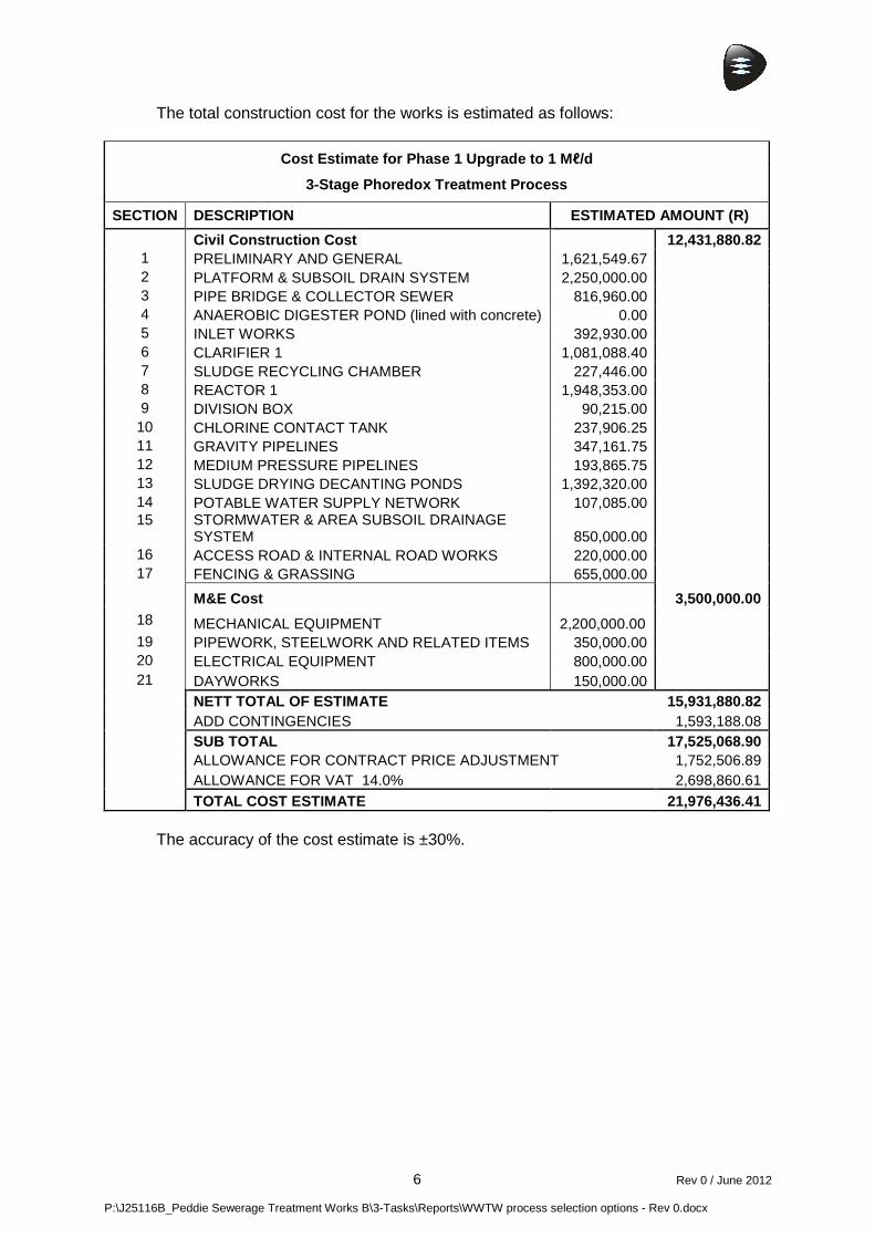
6 Rev 0 / June 2012 P:\J25116B_Peddie Sewerage Treatment Works B\3-Tasks\Reports\WWTW process selection options - Rev 0.docx
The total construction cost for the works is estimated as follows:
Cost Estimate for Phase 1 Upgrade to 1 M ℓ/d
3-Stage Phoredox Treatment Process
SECTION DESCRIPTION ESTIMATED AMOUNT (R)
Civil Construction Cost 12,431,880.82 1 PRELIMINARY AND GENERAL 1,621,549.67 2 PLATFORM & SUBSOIL DRAIN SYSTEM 2,250,000.00 3 PIPE BRIDGE & COLLECTOR SEWER 816,960.00 4 ANAEROBIC DIGESTER POND (lined with concrete) 0.00 5 INLET WORKS 392,930.00 6 CLARIFIER 1 1,081,088.40 7 SLUDGE RECYCLING CHAMBER 227,446.00 8 REACTOR 1 1,948,353.00 9 DIVISION BOX 90,215.00
10 CHLORINE CONTACT TANK 237,906.25 11 GRAVITY PIPELINES 347,161.75 12 MEDIUM PRESSURE PIPELINES 193,865.75 13 SLUDGE DRYING DECANTING PONDS 1,392,320.00 14 POTABLE WATER SUPPLY NETWORK 107,085.00 15 STORMWATER & AREA SUBSOIL DRAINAGE
SYSTEM 850,000.00 16 ACCESS ROAD & INTERNAL ROAD WORKS 220,000.00 17 FENCING & GRASSING 655,000.00 M&E Cost 3,500,000.00
18 MECHANICAL EQUIPMENT 2,200,000.00 19 PIPEWORK, STEELWORK AND RELATED ITEMS 350,000.00 20 ELECTRICAL EQUIPMENT 800,000.00 21 DAYWORKS 150,000.00
NETT TOTAL OF ESTIMATE 15,931,880.82 ADD CONTINGENCIES 1,593,188.08 SUB TOTAL 17,525,068.90 ALLOWANCE FOR CONTRACT PRICE ADJUSTMENT 1,752,506.89 ALLOWANCE FOR VAT 14.0% 2,698,860.61
TOTAL COST ESTIMATE 21,976,436.41 The accuracy of the cost estimate is ±30%.

7 Rev 0 / June 2012 P:\J25116B_Peddie Sewerage Treatment Works B\3-Tasks\Reports\WWTW process selection options - Rev 0.docx
The operational cost for the 3-Stage Phoredox works is estimated as follows:
ITEM DESCRIPTION Qty
Opera-tional at a time
kW/ unit
no of starts/
24h
Duration of
operation kWh/d kWh/Ml
1. ELECTRICAL OPERATION COST
Mixers 2 2 2 1 24 96 48
Aerators 4 2 16 1 20 640 320
Recycle Pumps 4 4 8 15 0.5 240 120
Secondary Clarifier Bridge 1 1 0.75 1 24 18 9
Disinfection : Chlorination 1 1 0.5 1 24 12 6
Dosing Pumps 2 2 0.5 1 12 12 6
Supernatant Pumps 2 2 10 3 0.5 30 15
Area Lighting 1 1 3.2 1 6 19.2 9.6
Building lights and plugs 1 1 2.5 1 6 15 7.5
TOTAL daily kW 2302.2 541.1
ITEM DESCRIPTION COST/MONTH UNIT
2.1 ELECTRICAL COST
Monthly usage (79.97c/kWh) R 26,323.66 per month
Demand fee (R18.63/KVA) R 5,868.45 per month
TOTAL expected monthly electrical cost R 32,192.11 per month
2.2 CHLORINATION COST
Flow (Ml/day) 2
Dosage rate for chlorine gas (mg/l) 5
Daily chlorine gas used (kg) 10
Average monthly chlorine gas used (kg) 304.17
Chlorine gas cost (R/kg) R 15.00
TOTAL expected monthly chlorine cost R 4,562.50 per month
2.3 LABOUR COST
Class II Operator x 5 (R/month) R 15,000.00
Class V Supervision x 1 (R/month) R 5,000.00
TOTAL expected monthly labour cost R 20,000.00 per month
EXPECTED MONTHLY OPERATION COST R 56,754.61 per mon th
EXPECTED ANNUAL OPERATION COST R 681,055.30 per yea r

8 Rev 0 / June 2012 P:\J25116B_Peddie Sewerage Treatment Works B\3-Tasks\Reports\WWTW process selection options - Rev 0.docx
3.4 Sequencing Batch Reactor
The sequencing batch reactor requires a high level of supervision. Incoming sewage is treated in batches – such a plant does not allow for continuous flow treatment. This requires two to three duty units, with one to two backups. This system was ruled out as an option as it is more suited to intermittent flows and requires skilled operators to manage the plant.
3.5 Package Plant Upgrade
The existing package plant has reached the end of its design life and the current flows exceed the capacity of the plant. In the long term, upgrading of this package plant would also not set up an acceptable foundation for future extensions and is therefore ruled out for further consideration.
3.6 Membrane Bio-Reactor
This option may be referred to as a “toilet-to-tap” system, as the final effluent can be returned to the potable water system. This is valuable in water-scarce areas. Water scarcity has, however, not been highlighted as an issue in the Peddie area, and the cost of operating this process to treat the effluent to potable standards is not warranted. As stated in “Wastewater Engineering Treatment and Reuse” (Medcalf & Eddy, fourth edition) : “Disadvantages of MBRs include high capital cost, limited data on membrane life, potential high cost of periodic membrane replacement, higher energy cost, and the need to control membrane fouling.” Membrane fouling control requires the operation and maintenance of a complex, chemically controlled backwash system. Continuous, as well as more aggressive periodic membrane fouling control measures, must be implemented. Membrane fouling control comprises 3 activities : 1. Coarse bubble aeration from the bottom of the membrane tank. 2. Interruption of filtration every 15 to 30 minutes for the membrane fibres to be
backwashed with permeate (5mg/ℓ chlorine concentration) for 45 seconds. (The system remains online during backwashing.)
3. Backwash with a strong sodium hypochlorite solution (100mg/ℓ) or citric acid for 45 minutes, three times per week.
Because of the complexity of operation and maintenance, as well as the complicated membrane fouling control process, MBR technology is not recommended for the Peddie WwTW.

9 Rev 0 / June 2012 P:\J25116B_Peddie Sewerage Treatment Works B\3-Tasks\Reports\WWTW process selection options - Rev 0.docx
3.7 Anaerobic Pond Combined with Activated Sludge
In this option an anaerobic pond is added between the inlet works and the reactor. The purpose of the pond is to reduce the COD load to the works mainly by changing the raw sewage to settled sewage. In the anaerobic pond the sludge reduction is estimated at 40-50%. The pond will, however, have to be cleaned periodically, owing to sludge build-up. The pond also allows reduction of the reactor volume by approximately 55%, and also reduces the oxygen demand from 1 624 kgO/d to 1 125 kgO/d. This equates to an approximate saving of 30% on aeration energy cost. The anaerobic pond is followed by a 3-Stage Phoredox treatment process utilizing a reduced reactor volume, as mentioned above. The unit processes required are as follows:
i) Inlet works ii) Concrete-lined anaerobic pond, 3.5 m deep with a total volume of 2730 m3 iii) Reactor with estimated total volume of 1472 m3, with anaerobic, anoxic and
aerobic zones for the removal of COD, nitrates and phosphates iv) Two secondary settling tanks with an estimated diameter of 16 m v) A chlorine contact tank with 40 minutes retention time at ADWF vi) Sludge drying beds vii) RAS and WAS pump stations viii) Associated mechanical and electrical equipment
If this option is selected, careful consideration should be given to the construction of a second anaerobic pond during Phase 1. If the pond is not maintained, the population growth and consequent increase in flow combined with the sludge build-up over time will result in short-circuiting within the pond. If this occurs, the reactor basin will be overloaded, and final effluent quality will be compromised. A second pond would serve as a backup measure, allowing for periodic maintenance of the first pond.

10 Rev 0 / June 2012 P:\J25116B_Peddie Sewerage Treatment Works B\3-Tasks\Reports\WWTW process selection options - Rev 0.docx
The total construction cost for the works is estimated as follows:
Cost Estimate for Phase 1 Upgrade to 1M ℓ/d Anaerobic Pond preceding 3-Stage Phoredox Treatment Process
SECTION DESCRIPTION ESTIMATED AMOUNT (R)
Civil Construction Cost 12,384,102.18 1 PRELIMINARY AND GENERAL 1,615,317.68 2 PLATFORM & SUBSOIL DRAIN SYSTEM 2,250,000.00 3 PIPE BRIDGE & COLLECTOR SEWER 816,960.00 4 ANAEROBIC DIGESTER POND (lined with concrete) 1,726,207.50 5 INLET WORKS 392,930.00 6 CLARIFIER 1 1,081,088.40 7 SLUDGE RECYCLING CHAMBER 227,446.00 8 REACTOR 1 876,758.85 9 DIVISION BOX 90,215.00
10 CHLORINE CONTACT TANK 237,906.25 11 GRAVITY PIPELINES 347,161.75 12 MEDIUM PRESSURE PIPELINES 193,865.75 13 SLUDGE DRYING DECANTING PONDS 696,160.00 14 POTABLE WATER SUPPLY NETWORK 107,085.00 15 STORMWATER & AREA SUBSOIL DRAINAGE SYSTEM 850,000.00 16 ACCESS ROAD & INTERNAL ROAD WORKS 220,000.00 17 FENCING & GRASSING 655,000.00 M&E Cost 3,000,000.00
18 MECHANICAL EQUIPMENT 1,800,000.00 19 PIPEWORK, STEELWORK AND RELATED ITEMS 300,000.00 20 ELECTRICAL EQUIPMENT 750,000.00 21 DAYWORKS 150,000.00
NETT TOTAL OF ESTIMATE 15,384,102.18 ADD CONTINGENCIES 1,538,410.22 SUB TOTAL 16,922,512.39 ALLOWANCE FOR CONTRACT PRICE ADJUSTMENT 1,692,251.24 ALLOWANCE FOR VAT 14.0% 2,606,066.91
TOTAL COST ESTIMATE 21,220,830.54 The accuracy of the cost estimate is ±30%.

11 Rev 0 / June 2012 P:\J25116B_Peddie Sewerage Treatment Works B\3-Tasks\Reports\WWTW process selection options - Rev 0.docx
The operational cost for the works is estimated as follows:
ITEM DESCRIPTION Qty Opera-
tional at a time
kW/ unit
no of starts/
24h
Duration of
operation kWh/d kWh/Ml
1. ELECTRICAL OPERATION COST
Mixers 2 2 2 1 24 96 48
Aerators 4 2 11.25 1 20 450 225
Recycle Pumps 4 4 8 15 0.5 240 120
Secondary Clarifier Bridge 1 1 0.75 1 24 18 9
Disinfection : Chlorination 1 1 0.5 1 24 12 6
Dosing Pumps 2 2 0.5 1 12 12 6
Supernatant Pumps 2 2 10 3 0.5 30 15
Area Lighting 1 1 3.2 1 6 19.2 9.6
Building lights and plugs 1 1 2.5 1 6 15 7.5
TOTAL daily kW 2302.2 446.1
ITEM DESCRIPTION COST/ MONTH UNIT
2.1 ELECTRICAL COST
Monthly usage (79.97c/kWh) R 21,702.06 per month
Demand fee (R18.63/KVA) R 5,868.45 per month
TOTAL expected monthly electrical cost R 27,570.51 per month
2.2 CHLORINATION COST
Flow (Ml/day) 2
Dosage rate for chlorine gas (mg/l) 5
Daily chlorine gas used (kg) 10
Average monthly chlorine gas used (kg) 304.17
Chlorine gas cost (R/kg) R 15.00
TOTAL expected monthly chlorine cost R 4,562.50 per month
2.3 LABOUR COST
Class II Operator x 5 (R/month) R 15,000.00
Class V Supervision x 1 (R/month) R 5,000.00
TOTAL expected monthly labour cost R 20,000.00 per month
EXPECTED MONTHLY OPERATION COST R 52,133.01 per mon th
EXPECTED ANNUAL OPERATION COST R 625,596.10 per yea r

12 Rev 0 / June 2012 P:\J25116B_Peddie Sewerage Treatment Works B\3-Tasks\Reports\WWTW process selection options - Rev 0.docx
4 RECOMMENDED OPTIONS
Of the 7 options discussed above, only Option 3 (Activated Sludge – 3-Stage Phoredox Process) and Option 7 (Anaerobic Pond Combined with Activated Sludge) would be appropriate and sustainable solutions for the Peddie WwTW upgrade, for the reasons discussed in Section 3. The construction cost and operational costs were taken into account in the tables presented in Section 3. Net Present Value (NPV) was used to compare these options, as summarised below :
Phase 1 Upgrade to 1M ℓ/d Lifecycle cost comparison between :
Option 3 (Activated Sludge – 3-Stage Phoredox Proce ss) and Option 7 (Anaerobic Pond Combined with Activated Sl udge)
Escalation 7%
Design Period 20 years
Year Description 3-Stage Phoredox An-pond + 3-Stage
Phoredox Difference 0 Capital Investment R 21,976,436.41 R 21,220,830.54 R 755,605.87 1 Energy, Chemicals and staff R 681,055.30 R 625,596.10 R 55,459.19 2 Energy, Chemicals and staff R 728,729.17 R 669,387.83 R 59,341.34 3 Energy, Chemicals and staff R 779,740.21 R 716,244.98 R 63,495.23 4 Energy, Chemicals and staff R 834,322.03 R 766,382.13 R 67,939.90 5 Energy, Chemicals and staff R 892,724.57 R 820,028.88 R 72,695.69 6 Energy, Chemicals and staff R 955,215.29 R 877,430.90 R 77,784.39 7 Energy, Chemicals and staff R 1,022,080.36 R 938,851.06 R 83,229.30 8 Energy, Chemicals and staff R 1,093,625.98 R 1,004,570.64 R 89,055.35 9 Energy, Chemicals and staff R 1,170,179.80 R 1,074,890.58 R 95,289.22 10 Energy, Chemicals and staff R 1,252,092.39 R 1,150,132.92 R 101,959.47 11 Energy, Chemicals and staff R 1,339,738.86 R 1,230,642.23 R 109,096.63 12 Energy, Chemicals and staff R 1,433,520.58 R 1,316,787.18 R 116,733.39 13 Energy, Chemicals and staff R 1,533,867.02 R 1,408,962.28 R 124,904.73 14 Energy, Chemicals and staff R 1,641,237.71 R 1,507,589.64 R 133,648.06 15 Energy, Chemicals and staff R 1,756,124.35 R 1,613,120.92 R 143,003.43 16 Energy, Chemicals and staff R 1,879,053.05 R 1,726,039.38 R 153,013.67 17 Energy, Chemicals and staff R 2,010,586.76 R 1,846,862.14 R 163,724.63 18 Energy, Chemicals and staff R 2,151,327.84 R 1,976,142.49 R 175,185.35 19 Energy, Chemicals and staff R 2,301,920.79 R 2,114,472.46 R 187,448.32 20 Energy, Chemicals and staff R 2,463,055.24 R 2,262,485.54 R 200,569.71
Total Cost R 49,896,633.69 R 46,867,450.82 R 3,029,182.87 Nett Present Value R 32,435,927.10 R 30,760,949.22 R 1,674,977.88

13 Rev 0 / June 2012 P:\J25116B_Peddie Sewerage Treatment Works B\3-Tasks\Reports\WWTW process selection options - Rev 0.docx
A comparison of the two recommended options yields the following :
i) The construction cost for Option 3 is estimated to be approximately 4% greater than that for Option 7.
ii) The operational cost for Option 3 is estimated to be 19% greater than that for Option 7.
iii) The NPV for the lifecycle cost over 20 years is estimated to be R 32,435,927.10 for Option 3 and R 30,760,949.22 for Option 7. This equates to an NPV difference of R 1,674,977.88.
iv) For the first upgrade of the works to a capacity of 1.0 Mℓ/d which caters for an estimated population of 10,127 people, the following cost per head has been calculated from the costs given under Section 3.
Cost per head
Description 3-Stage
Phoredox An-pond +
3-Stage Phoredox Difference Capital Cost R 2,170.08 R 2,095.47 R 74.61 Monthly Operational Cost R 5.60 R 5.15 R 0.46
v) The physical differences between the two options are as follows :
No Description Option 3: 3-Stage Phoredox
Option 7: Anaerobic pond + 3-Stage
Phoredox
1 Anaerobic digester pond volume No pond 2731 m3
2 Reactor volume 3480 m3 1472 m3
3 Sludge drying decanting ponds area
16 beds: 10 m x 20 m
8 beds: 10 m x 20 m
vi) In Option 3 the reactor basin is sized to treat raw sewage. In Option 7 the
anaerobic pond serves as both a primary settling tank and an anaerobic digestion tank, which reduces the raw settled sludge by 40-50%. The reactor basin is therefore sized to treat this reduced flow volume from the anaerobic pond.
vii) In Option 3 the sludge is handled and dried as per the required WAS rate. In Option 7 raw sewage is settled and mixed with WAS, during which the anaerobic process reduces the sludge volume as indicated above.
viii) In Option 7 the anaerobic pond reduces the sludge volume and provides a few years sludge storage. This reduces the required number of drying beds by roughly half that necessary for Option 3.

14 Rev 0 / June 2012 P:\J25116B_Peddie Sewerage Treatment Works B\3-Tasks\Reports\WWTW process selection options - Rev 0.docx
5 CONCLUSION
Appropriate treatment options for plants of capacity 500 kℓ/d to 2 000 kℓ/d all require some aeration component. It has been established that either an activated sludge (3-Stage Phoredox process) or an anaerobic pond combined with activated sludge plant is most suitable for implementation at the Peddie WwTW. The anaerobic pond in Option 7 is added for primary settling and anaerobic treatment of the raw sewage. The two recommended options fulfill the 5 main design criteria for establishing a sanitation system as follows: a) Reliability - An AS plant can absorb some variation to the incoming sewage and
also accommodate power failures to a certain extent. b) Acceptability & Appropriateness – AS plants have been successfully
implemented throughout South Africa. c) Affordability – The capital and operational cost per month per head were
estimated as follows:
Cost per head
Description 3-Stage Phoredox An-pond +
3-Stage Phoredox Difference Capital Cost R 2,170.08 R 2,095.47 R 74.61 Monthly Operational Cost R 5.60 R 5.15 R 0.46
d) Sustainability - These plants are simplistic and relatively easy to operate. Based on the discussed options and costings, ADM are to take a decision as to the preferred treatment process, before Detail Design may commence.
