the role of geosynthetics in erosion and sediment … role of geosynthetics in... · the role of...
TRANSCRIPT
Geotextiles and Geomembranes I I (1992) 535-550
The Role of Geosynthetics in Erosion and Sediment Control: An Overview
M. S. T h e i s e n
Erosion Control Materials, Synthetic Industries, Construction Products Division, 4019 Industry Drive, Chattanooga, Tennessee 37416, USA
ABSTRACT
The use of geosynthetic erosion and sediment materials continues to expand at a rapid pace. From their early beginnings in the late 1950s, geosynthetic materials today are the backbone of the erosion and sediment control industry. Geosynthetic components are an integral part of erosion and sediment materials ranging from temporary products such as hydraulic mulch geofibers, plastic erosion control meshes and nettings, erosion control blankets and silt fences to high performance turf reinforcement mats, geocellular confinement systems, erosion control geotextiles and fabric formed revetments. This paper provides a brief overview of these materials and concepts.
INTRODUCTION
Hopefully we are entering a new environmental era where concern for the protection of our planet's natural resources will reach global proportions. Cont inued technological advances have led to improved monitoring of Earth's vital signs. As such, prior theoretical modeling of environmental concerns such as the greenhouse effect, ozone depletion, rising sea levels, deforestation, drought, accelerated erosion, sediment loading of waterways, species extinction and the eventual downfall of mank ind appear chillingly realistic.
535
536 M. S. Theisen
Slogans such as 'Think globally, act locally', 'Love your mother' and 'Someone always lives downstream' are spearheading the efforts of numerous preservation groups. With the continued demise of oppressive governments, optimism for world peace and an unprecedented feeling of global unity, a spirit of environmental cooperation is beginning to prevail.
The term 'non-point pollution' hopefully is heading toward obsolescence with groups such as Stream Watch sloshing their way up muddy creeks to pinpoint sources of unchecked sediment. Improved methods to detect and monitor rates of erosion and sedimentation via high tech satellite imagery or even the actions of the Stream Watchers of the world lends credence to the old saying 'you can run but you can't hide'. Generators of sediment and other pollutants can and will be identified.
Cumulative research suggests excessive sediment in our waterways is the planet's most prevalent contaminant. Increscent economic and social losses from reductions in arable farmland, timber production, fishery yields, species diversity and navigable waterways exceed those caused by pollutants in the public eye such as nuclear and hazardous wastes, smog or ground water contamination. Worse yet, the problem is exasperated as one moves downstream toward our coastlines and population centers.
Recently a number of laws have been mandated in the United States to combat excessive erosion. Such legislation ranges from local erosion and sediment control ordinances to numerous state and federal agricultural, waste containment and surface mining acts, to the broadly encompassing Environmental Protection Agency's Clean Water Act and The Farm Bill administered by the Department of Agriculture. These actions are only the tip of the iceberg as more and more government agencies and entities get with the program.
Just what is erosion control? To control erosion is to curb or restrain (not completely stop) the gradual or sudden wearing away of soils. One has seen extreme examples of excessive erosion such as gullied hill slopes or stream channels choked with debris, but often erosion goes unchecked on fiat to moderately sloping terrain. Soil loss is a continually occurring process in natural ecosystems as well as successfully reclaimed sites--without it our scenery would be very boring. The goal of any revegetation or erosion control project should be to stabilize soils and manage erosion in an economical manner (Theisen, 1988).
In this era of shrinking budgets, decision makers are hard pressed to reclaim disturbed sites at minimum costs. Given site conditions such as slope angles, climate, runoff, soil profile and ultimate land use, a
Geosynthetics in erosion and sediment control 537
specifier must select with confidence a technique he (she) feels will perform up to expectations at the lowest cost. Over the past 25 years the erosion control industry has experienced rapid growth and is becoming more sophisticated. Materials developed for erosion and sediment control (E & SC) are becoming increasingly effective. Improved design and installation guidelines are directing the use of E & SC products toward more specific and cost effective applications. The industry has evolved from the seed drills, straw blowers, hydroseeders, excelsior, jute, concrete channel liners and rip rap of the sixties into a diverse hierarchy of techniques and materials. It seems as if every month a new product is introduced to control erosion and sediment in more specific situations. Numerous materials have come and gone in the survival of the fittest, most cost competitive products.
Historical perspective
Many of us perceive the use of geosynthetic materials for erosion and sediment control as a new horizon. However, geosynthetics have played a major role in the E & SC industry for over 30 years, particularly in the case of rolled goods. In 1958 a geosynthetic component was incorporated into an erosion control system which has changed the course of slope, channel and embankment protection. A'plastic cloth' was used in lieu of a granular filter to prevent sand from washing out behind concrete blocks used for shoreline protection (Richardson & Koerner, 1990). The significant cost savings realized when a 0.4-mm thick plastic filter cloth could replace up to a meter of soil peaked the interest of the US Army Corps of Engineers. Subsequent successful installations of woven plastic cloth filters in coastal Structures led to the birth of the geotextile industry as is practiced today. Through the years millions of square yards of woven and non woven geotextiles have been installed as part of hard armor systems.
Another geosynthetic breakthrough was initiated about 10 years later. In the mid 1960s only one type of erosion control blanket existed. A state soil conservationist discovered the material used for wrapping cotton bales could be used to prevent soil erosion. The material was jute, a woven mesh of thick natural yarns, when applied on the soil surface provided thousands of tiny check dams to help keep soil from washing away. Jute blankets allow vegetation to become established on steeper slopes and in higher flowing swales than traditional straw and hay mulches. A similar material remains in use today.
However, jute has its drawbacks: its open weave construction leaves
538 M. S Theisen
soil exposed, the organic material tends to shrink and swell under field conditions, and it is extremely flammable. To achieve opt imum results straw or hay mulch still must be placed beneath the jute.
What was needed was a one step, roll out mulch blanket. The first attempts involved a very dense mat of curled, barbed aspen wood (excelsior) fibers. The material stayed together but was too dense to allow vegetative growth. Next, a twisted kraft paper net was placed above a thinner mat of excelsior fibers. Vegetation grew through the blanket but performance of the paper netting was very inconsistent; often breaking down too quickly and being lifted by the vegetation or, worse yet, allowing the blanket to be washed away before vegetative establishment. A stronger, non-moisture sensitive, more durable netting was needed. Polypropylene netting was the answer.
Combining a dense mat of excelsior with a plastic net lead to the first successful excelsior erosion control blankets. Field trials with various nets, fiber lengths and glue patterns resulted in essentially the same blankets we see today. The key to the improved performance of excelsior over jute blankets is the plastic net backbone of the product.
Biaxially oriented process nets
Biaxially oriented process (BOP) nets are typically manufactured from polypropylene or polyethylene resins. BOP nets are extremely versatile in that composition, strength, elongation, aperture size and shape, color and ultraviolet stability can easily be designed into the product for specific site requirements. Since they do not absorb moisture, these nets do not shrink and swell like kraft paper nets and jute blankets. BOP nets have proven to be so adaptable they are being used to create more complex products and are even used alone to anchor loose fiber mulches such as straw, hay and wood chips. The lightweight nettings placed over mulches come in rolls which are 3-4.5 m in width, weigh only about 55 kg and will cover 0.4 h (1 acre) or more. Installation of these products is less labor intensive than traditional netting products.
Erosion control meshes
A step up from BOP nettings are woven polypropylene geotextile erosion control meshes. In fact, the newer twisted fiber erosion control meshes can provide comparable performance to erosion control blankets. These photobiodegradable, natural looking, high strength polypropylene meshes protect the soil surface from water and wind erosion while accelerating vegetative development. Four meter, lightweight rolls facilitate installation on slopes and channels. Erosion control meshes
Geosynthetics in erosion and sediment control 539
may be used alone, with dry mulches or as a stabilizing underlay for sod reinforcement. They also show promise as an open weave geotextile facing for fostering vegetation on geosynthetically reinforced steepened slopes or bioengineering installations.
Erosion control blankets (ECBs)
BOP nettings or woven meshes of varying characteristics are now placed on one or both sides of finely tuned erosion control blankets adapted to anticipated site conditions. These 1-2-m wide biodegradable fiber erosion control blankets (ECBs) are composed of straw, excelsior, cotton, coconut, polypropylene or blends thereof. Nettings or meshes may contain UV stabilizers for controlled degradation or long chain interrupters to accelerate photodegradation. Colors vary from clear, tan, green to black. Methods of holding the fibers in place range from glues and glue strips to more superior parallel lock stitching with cotton, polyester or polyolefin threads. Applications for the wide variety of blankets range from protection of gradual to steep slopes to low or moderately flowing channels. These blankets may provide temporary resistance to flow velocities of up to nearly three meters per second.
Finally and perhaps of most concern to the environment, these meshes and nettings may ultimately become biodegradable. As photo- degradation progresses the plastic chains are cut into shorter and shorter segments down to a plastic 'sand' which becomes part of the soil. These short segments become biologically degradable and are attacked by soil microorganisms and converted to carbon dioxide and water (Guillet, 1974). It is unfortunate that emotional, uninformed anti-plastic stigmas sometimes preclude the use of these extremely cost effective temporary materials.
TERMs versus PERMs
At this point an important distinction must be presented regarding the intended use of E & SC materials. For many installations vegetation alone will provide adequate long term erosion protection. However, getting vegetation established requires a variety of techniques. Materials of a temporary nature which facilitate vegetative establishment, then degrade, may be termed TERMs (temporary erosion and revegetation materials).
Basically TERMs consist of degradable natural and/or synthetic components which provide temporary erosion control and faciltate vegetative establishment. These short term materials degrade leaving
540 M. S. Theisen
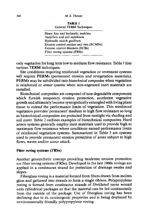
TABLE 1 General TERM Techniques
Straw, hay and hydraulic mulches Tackifiers and soil stabilizers Hydraulic mulch geofibers Erosion control meshes and nets (ECMNs) Erosion control blankets (ECBs) Fiber roving systems (FRSs)
only vegetation for long term low to medium flow resistance. Table 1 lists various TERM techniques.
Site conditions requiring reinforced vegetation or revetment systems will require PERMs (permanent erosion and revegetation materials). PERMs may be subdivided into biotechnical composites when vegetation is reinforced or armor systems when non-vegetated inert materials are installed.
Biotechnical composites are composed of non-degradable components which furnish temporary erosion protection, accelerate vegetative growth and ultimately become synergistically entangled with living plant tissue to extend the performance limits of vegetation. This reinforced vegetation provides 'permanent' medium to high flow resistance so long as biotechnical composites are protected from sunlight via shading and soil cover. Table 2 outlines examples of biotechnical composites. Hard armor systems generally employ inert materials used to provide high to maximum flow resistance where conditions exceed performance limits of reinforced vegetation systems. Summarized in Table 3 are systems used to provide permanent erosion protection of areas subject to high flows, waves and/or scour attack.
Fiber roving systems (FRSs)
Another geosynthetic concept providing moderate erosion protection are fiber roving systems (FRSs). Developed in the late 1960s rovings are applied in a continuous strand for protection of drainage swales and slopes.
Fiberglass roving is a material formed from fibers drawn from molten glass and gathered into strands to form a single ribbon. Polypropylene roving is formed from continuous strands of fibrillated yarns wound onto cylindrical packages so that the material can be fed continuously from the outside of the package. Use of fiberglass roving has been declining due to its carcinogenic properties and is being displaced by environmentally friendly polypropylene roving.
Geosynthetics in erosion and sediment control 541
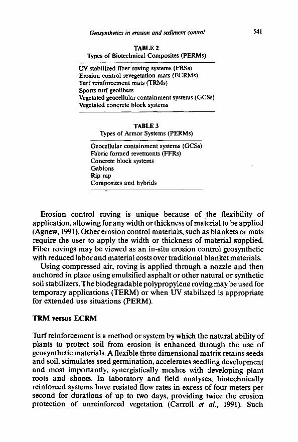
TABLE 2 Types of Biotechnical Composites (PERMs)
UV stabilized fiber roving systems (FRSs) Erosion control revegetation mats (ECRMs) Tuff reinforcement mats fiRMs) Sports turf geofibers Vegetated geocellular containment systems (GCSs) Vegetated concrete block systems
TABLE 3 Types of Armor Systems (PERMs)
Geocellular containment systems (GCSs) Fabric formed revetments (FFRs) Concrete block systems Gabions Rip rap Composites and hybrids
Erosion control roving is unique because of the flexibility of application, allowing for any width or thickness of material to be applied (Agnew, 1991). Other erosion control materials, such as blankets or mats require the user to apply the width or thickness of material supplied. Fiber rovings may be viewed as an in-situ erosion control geosynthetic with reduced labor and material costs over traditional blanket materials.
Using compressed air, roving is applied through a nozzle and then anchored in place using emulsified asphalt or other natural or synthetic soil stabilizers. The biodegradable polypropylene roving may be used for temporary applications (TERM) or when UV stabilized is appropriate for extended use situations (PERM).
T R M versus E C R M
Turf reinforcement is a method or system by which the natural ability of plants to protect soil from erosion is enhanced through the use of geosynthetic materials. A flexible three dimensional matrix retains seeds and soil, stimulates seed germination, accelerates seedling development and most importantly, synergistically meshes with developing plant roots and shoots. In laboratory and field analyses, biotechnically reinforced systems have resisted flow rates in excess of four meters per second for durations of up to two days, providing twice the erosion protection of unreinforced vegetation (Carroll et al., 1991). Such
542 M. S Theisen
performance has resulted in the widespread practice of turf reinforce- ment as an alternative to concrete, rip rap and other armor systems in the protection of open channels, drainage ditches, detention basins and steepened slopes.
Permanent geosynthetic mattings are composed of durable synthetic materials stabilized against ultraviolet degradation and inert to chemicals normally encountered in a natural soil environment. These mattings consist of a lofty web of mechanically or melt bonded polymer nettings, monofilaments or fibers which are entangled to form a strong and dimensionally stable matrix. Polymers include polypropylene, poly- ethylene, nylon and polyvinyl chloride.
Geosynthetic mattings generally fall into two categories: turf reinforce- ment mats (TRMs) or erosion control revegetation mats (ECRMs). Higher strength TRMs provide sufficient thickness and void space to permit soil filling/retention and the development of vegetation within the matrix. TRMs are installed first, then seeded and filled with soil. Seeded prior to installation, ECRMs are denser, lower profile mats designed to provide long term ground cover and erosion protection, By their nature of installation TRMs can be expected to provide more vegetative entangle- ment and long term performance than ECRMs. However, denser ECRMs may provide superior temporary erosion protection.
Geoceilular containment systems (GCSs)
Geocellular containment systems work in a unique fashion in that strength or stabilization by confinement is achieved by a series of three- dimensional cells up to 20 cm deep. When expanded into position, the polyethylene or polyester cells have the appearance of a large honeycomb, one of nature's most efficient structures. The cells are then backfilled with soil, sand or gravel depending upon application. For revegetation, the soil-backfilled cells are seeded, fertilized and covered with a variety of TERM or PERM techniques. The mulches provide surface protection while the cells greatly reduce the chances of subsurface failure and act as a deeper rooted biotechnical composite. Vegetated GCSs are limited to flow velocities of two to three meters/second because of the tendency of the nearly impermeable cells to sustain scouring under high flow velocities (Chen & Anderson, 1986).
For higher flow conditions GCSs may be also filled with concrete or gravel to create a hard armor system. Typically a geotextile will be placed beneath the expanded web to provide separation and/or filtration. Erosion control applications for GCSs are many including steep slope revegetation, channel liners, shoreline revetments, retaining walls, boat ramps, and low flow stream crossings.
Geosynthetics in erosion and sediment control 543
Fabric formed revetments
Fabric forming systems are mattresses typically constructed of water permeable, double layer woven geotextiles which are positioned on the area to be protected and filled with a structural grout. The two layers of geotextile are joined at discrete points to create a form which when filled with grout will conform to most subsoil conditions. Thickness and geometry are determined by internal spacer threads woven into the upper and lower sheets of fabric. In many cases the mattresses may be installed for less cost than conventional armor systems since all construction is conducted in place (Richardson & Koerner, 1990).
Concrete block systems
Concrete block systems consist of prefabricated concrete panels of various geometries which may be attached to and laid upon a woven monofilament or non-woven geotextile. Bending and torsion are accommodated by having the concrete blocks articulated with joints, weaving patterns or connection devices. Concrete block systems may be subdivided into three groups: non-tied interlocking blocks, cable-tied blocks, or in-situ concrete (Hewlett et al., 1987). In some cases the entire erosion control section may be manufactured, trucked to the job site and placed as a unit.
Gabions
Gabions are compartmented rectangular containers made of galvanized steel hexagonal wire mesh and filled with hand-sized stone. Cells of equal capacity are formed by factory-inserted wire netting diaphragms or partitions which add strength to the container and help maintain its shape during the placement of stone. In highly corrosive conditions a polyvinyl chloride coating is used over the galvanized wire.
Advantages of gabions include flexibility, durability, strength, per- meability and economy versus rigid structures. The growth of native plants is promoted as gabions collect sediment in the stone fill. A high percentage of installations are underlain by woven monofilament and nonwoven geotextiles to facilitate sediment capture and prevent wash out from behind the structure.
Rip rap
Rip rap consists of stone dumped in place on a filter blanket or prepared slope to form a well graded mass with a minimum of voids. Stone used for
544 M. S. Theisen
rip rap is hard, durable, angular in shape; resistant to weathering and to water action; and free from overburden, spoil, shale and organic material. The rip rap material is generally placed on a gravel bedding layer and/or a woven monofilament or nonwoven geotextile fabric.
Performance of erosion control materials
Several test procedures have been proposed to quantify performance of erosion control materials. Initial concern for vegetated systems is temporary erosion protection prior to and during seed germination and seedling development. Typically, this level of performance is measured by the material's ability to minimize soil loss when subjected to various flow rates and/or rainfall amounts. Temporary erosion protection is important but the long term goal of any erosion control matrix is to provide permanent erosion protection via permanent vegetation and/or subsequent root reinforcement. The more rapidly vegetation becomes established the more rapidly long term erosion control may be accomplished. Thus, the material's ability to facilitate vegetative establishment is equally important. Too much emphasis on an erosion control product's temporary protection may inhibit the growth of newly emerging seedlings.
Perhaps the most critical parameter in an engineering design is flow resistance before, during and long after vegetative establishment. Some erosion control materials may be washed away before the vegetation takes hold while others may temporarily exhibit excellent flow resistance only to lose their effectiveness as they degrade or decompose over time. Specifiers must take into account immediate and long term flow resistance based upon longevity of the material when designing grassed slopes and waterways.
Two basic design concepts are used to evaluate and define a channel configuration that will perform within accepted limits of stability. These methods are defined as the permissible velocity approach and the permissible tractive force (shear stress) approach. Under the permissible velocity approach the channel is assumed stable if the adopted velocity is lower than the maximum permissible velocity. The tractive force (boundary shear stress) approach focuses on stresses developed at the interface between flowing water and the materials forming the channel boundary (Chen& Cotton, 1988).
The permissible velocity approach uses Manning's equation where with given depth of flow, D, the mean velocity may be calculated as:
V = R2/3Sl/2/n
Geosynthetics in erosion and sediment control 5 4 5
where
V = n - -
R =
average velocity in the cross section Manning's roughness coefficient hydraulic radius, equal to the cross-sectional area,A, divided by the wetted perimeter, P
S = friction slope of the channel, approximated by the average bed slope for uniform flow conditions
The tractive force approach uses a simplified shear stress analysis which is equal to:
where • ¢" =
y = D = S =
yDS
tractive force unit weight of water maximum depth of flow average bed slope or energy slope
Design criteria based on flow velocity may be limited because maximum velocities vary widely with channel length (L), shape (R), and roughness coefficients (n). In reality it is the force developed by the flow, not the flow velocity itself, that challenges the performance of erosion control systems. Tractive forces caused by flowing water over the ground surface create shear stresses which can be used as a design parameter independent of channel shape and roughness. Moreover, the higher stresses developed in channel bends or other changes in stream channel geometry can be quantified by simplified shear stress calculations, providing a higher level of design confidence than otherwise possible (Chen & Cotton, 1988).
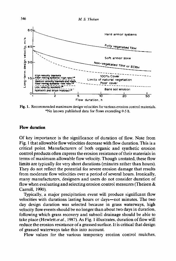
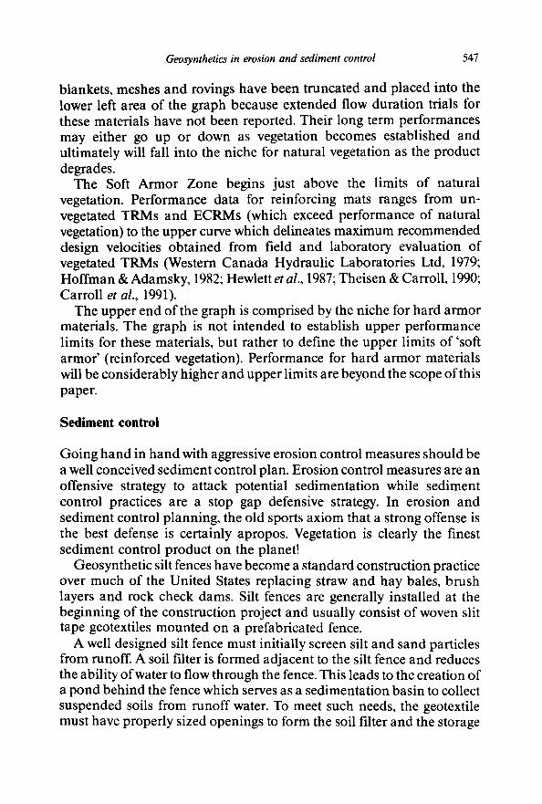
Critical shear stress determinations are meant to be used with velocity calculations for prescreening of channel lining designs. Manning's equation remains the primary hydraulic research and design tool. However, as everyday practice has determined, a simplified screening criteria such as maximum shear stress is necessary to ensure properly engineered design of channel lining erosion control systems. Figure 1 combines cumulative research for several erosion control materials and attempts to group categories of erosion control materials into their cost effective design niches.
Maximum permissible velocities for vegetative techniques are illustrated under vegetated and non-vegetated conditions. Thus a designer will have performance guidelines from the time a material is installed to when it becomes fully vegetated.
546 M. S. Theisen
6'0
E ~, 4 . 5
.90 :>
r -
.~ 3-0 u~
10
E 1-5 i
17D E 0
._l
High velocity blankets _fiber roving systems- high r a t e ? ~
Medium velocity blankets and mesh fiber roving systems-low rate?X - ~ Low v~ocit~; ~ l ; ~ ; P . . . . .
I I 2 5
Flow dura t ion , h
Hard a r m o r systems
~ t e d TRM
Soft a r m o r zone
N ° n ' v e g e t a t e d TRM or ECRM
100°1. Cover . . . . . . . . . . L imi ts of natura l vege ta t ion
Poor cover
Bare soil erosion
I I I 10 20 50
Fig. 1. Recommended maximum design velocities for various erosion control materials. *No known published data for flows exceeding 0.5 h.
Flow duration
Of key importance is the significance of duration of flow. Note from Fig. 1 that allowable flow velocities decrease with flow duration. This is a critical point. Manufacturers of both organic and synthetic erosion control products often express the erosion resistance of their materials in terms of maximum allowable flow velocity. Though unstated, these flow limits are typically for very short durations (minutes rather than hours). They do not reflect the potential for severe erosion damage that results from moderate flow velocities over a period of several hours. Ironically, many manufacturers, designers and users do not consider duration of flow when evaluating and selecting erosion control measures (Theisen & Carroll, 1990).
Typically, a major precipitation event will produce significant flow velocities with durations lasting hours or days--not minutes. The two day design duration was selected because in grass waterways, high velocity flow events should be no longer than about two days in duration, following which grass recovery and subsoil drainage should be able to take place (Hewlett et al., 1987). As Fig. 1 illustrates, duration of flow will reduce the erosion resistance of a grassed surface. It is critical that design of grassed waterways take this into account.
Flow values for the various temporary erosion control mulches,
Geosynthetics in erosion and sediment control 547
blankets, meshes and rovings have been truncated and placed into the lower left area of the graph because extended flow duration trials for these materials have not been reported. Their long term performances may either go up or down as vegetation becomes established and ultimately will fall into the niche for natural vegetation as the product degrades.
The Soft Armor Zone begins just above the limits of natural vegetation. Performance data for reinforcing mats ranges from un- vegetated TRMs and ECRMs (which exceed performance of natural vegetation) to the upper curve which delineates maximum recommended design velocities obtained from field and laboratory evaluation of vegetated TRMs (Western Canada Hydraulic Laboratories Ltd, 1979; Hoffman & Adamsky, 1982; Hewlett et al., 1987; Theisen & Carroll, 1990; Carroll et al., 1991).
The upper end of the graph is comprised by the niche for hard armor materials. The graph is not intended to establish upper performance limits for these materials, but rather to define the upper limits of 'soft armor' (reinforced vegetation). Performance for hard armor materials will be considerably higher and upper limits are beyond the scope of this paper.
Sediment control
Going hand in hand with aggressive erosion control measures should be a well conceived sediment control plan. Erosion control measures are an offensive strategy to attack potential sedimentation while sediment control practices are a stop gap defensive strategy. In erosion and sediment control planning, the old sports axiom that a strong offense is the best defense is certainly apropos. Vegetation is clearly the finest sediment control product on the planet!
Geosynthetic silt fences have become a standard construction practice over much of the United States replacing straw and hay bales, brush layers and rock check dams. Silt fences are generally installed at the beginning of the construction project and usually consist of woven slit tape geotextiles mounted on a prefabricated fence.
A well designed silt fence must initially screen silt and sand particles from runoff. A soil filter is formed adjacent to the silt fence and reduces the ability of water to flow through the fence. This leads to the creation of a pond behind the fence which serves as a sedimentation basin to collect suspended soils from runoff water. To meet such needs, the geotextile must have properly sized openings to form the soil filter and the storage
548 M. S. Theisen
capacity of the fence must be adequate to contain the volume of water and sediment anticipated during a major storm (Richardson & Koerner, 1990).
Porous sediment control structures are the newest geosynthetic approach to sediment control. A three-dimensional moldable mass of crimped polypropylene fibers may be placed in fills or gullies to provide passive sediment control. Placed by hand with its size and shape determined by the installer, applications include fill and gully repair, ditch checks, sediment traps, and perimeter berming. Moreover the fibers may be encapsulated in a polypropylene mesh to create prefabricated check dams for swale and ditch protection. Table 4 lists a few sediment control techniques.
Other geosynthetic opportunities
Ideas for geosynthetic erosion and sediment control materials abound. Certainly new ideas have been omitted or are being developed at the time of this publication. Odds are high that geosynthetics will work their way down the ladder into more traditional applications such as hydraulic mulches and erosion control blankets. Hydraulic mulch geofibers (which improve the tenacity of wood fiber and recycled paper mulches) and recycled plastic fiber blankets and mats are already entering the market. Geofibers are being used as part of sports turf systems in major athletic stadiums providing both ground stabilization and a root reinforcing matrix.
The future of geosynthetics for E & SC lies partly in the recycling Of waste plastics generated from other applications. Polymer specifications for E & SC applications are not as stringent as other geosynthetic materials such as geomembranes, geogrids and geotextiles. It is an environmentally friendly gesture in an environmentally friendly industry. And recycled plastics are cost effective.
TABLE 4 Examples of Sediment Control Techniques
Vegetation Straw and hay bales Brush layers Silt fences Porous sediment control structures (PSCSs) Rock check dams Sediment traps, basins and ponds
Geosynthetics in erosion and sediment control 549
More research on E & SC effectiveness of the myriad of materials is mandatory. Questions regarding resistance to extended flow durations and long term performance for all materials must be answered. Systems must be developed for standardizing product descriptions, sanctioning uniform test and evaluation procedures, and creating a market reporting system to insure broad acceptance of E & SC industry. Organizations such as the International Erosion Control Association (IECA), Erosion Control Technology Council (ECTC), American Society for the Testing of Materials (ASTM), Industrial Fabrics Association International (IFAI), and the Geosynthetics Research Institute (GRI) must lead the way.
Another hurdle to overcome or trail to blaze, depending upon how one looks at it, is the issue of biodegradable plastics for short term applications. This is an area of very important research. Members of the industry as well as the general public must be educated. The performance advantages of man made fibers over natural fibers is recognized in many sectors of the textile industry. The E & SC industry is quite possibly a sleeping giant for man made fibers. Keep your ear to the ground and your eyes wide open because 'you ain't seen nothin' yet'. The future of geosynthetics in erosion and sediment control is bright!
REFERENCES
Agnew, W. (1991). Erosion control product selection. Geotechnical Fabrics Report, 9 (3), 24-27.
Carroll, O. Jr, Rodencal, J. & Theisen, M. S. (1991). Evaluation of turf reinforcement mats and erosion control and revegetation mats under high velocity flows. Proceedings of the XXII Annual Conference of the International Erosion Control Association, Orlando, FL.
Chen, Y. H. & Anderson, B. A. (1986). Development of a methodology for estimating embankment damage due to flood overtopping. USDOT Federal Highway Administration and USDA Forest Service, report number DTFH61-82-C-00104, Ft Collins, CO.
Chen, Y. H. & Cotton, G. K. (1988). Design of roadside channels with flexible linings. Federal Highway Administration report HEC-15/FHWA-1P-87-7, McLean, VA.
Guillet, J. E. (1974). Plastics, energy and ecology--a harmonious triad. Plastics Engineering, 30 (8), 48-56.
Hewlett, H. W. M., Boorman, L. A. & Bramley, M. E. (1987). Design of re- inforced grass waterways. Construction Industry Research and Information Association, Report 116, London.
Hoffman, G. L. & Adamsky, R. (1982). Nylon erosion control mat. Presented at the Transportation Research Board sixty-first annual meeting Washington DC.
Theisen, M. S. (1988). Cost-effective techniques for successful erosion control. Proceedings High Altitude Revegetation Workshop No. 8, Ft Collins, CO.
Theisen, M. S. & Carroll, R. G. (1990). Turf reinforcement--the 'soft armor"

550 M. S. Theisen
alternative. Proceedings of the XXI Annual Conference of the International Erosion Control Association, Washington DC.
Richardson, G. N. & Koemer, R. M. (eds) (1990).A Design Primer." Geotextiles and Related Materials, Industrial Fabrics Association International, St Paul, MN.
Western Canada Hydraulic Laboratories Ltd (1979). Cove Country Club: Experimental Studies on Permissible Shear Stresses of Bermuda Grass. Port Coquilam, British Columbia, Canada.