stationary battery testing brochure -...
TRANSCRIPT
Stationary Battery Testing
Brochure
STATIONARY BATTERY TESTINGThe stationary backup batteries are the life line in any safety system, a life line that simply cannot fail. In order to ensure safe operation it is recommended to implement a sound and solid battery maintenance program.
Each of the various standards (IEEE 450, IEEE 1188, IEEE 1106) have their own best practices for battery maintenance, which we have summarized into the following:
■ Perform a capacity test when the battery is new as part of the acceptance test.
■ Perform an impedance test at the same time to establish baseline values for the battery.
■ Repeat the above within 2 years for warranty purposes.
■ Perform an impedance test every year on flooded cells and quarterly on VRLA cells.
■ Perform capacity tests at least for every 25% of expected service life.
■ Perform a capacity test annually when the battery has reached 85% of expected service life or if the capacity has dropped more than 10% since the previous test or is below 90% of the manufacturer‘s rating.
■ Perform a capacity test if the Impedance value has changed significantly.
■ Follow a given practice (preferably from the IEEE standard) for all temperature, voltage, gravity measurements etc. and fill in a report. This will be a great help for trending and fault tracing.
This is an example of the tests included in a good maintenance program for stationary batteries. However, some critical locations might need more attention, and some rural environments less, the condition of the environment of the battery and the condition of the battery itself are important parameters to set up a suitable and solid maintenance program.
Why perform impedance testing?
Batteries can fail between discharge tests. This quick easy test will increase reliability for your critical loads.
Not only will this inform you about chemical changes in your batteries but it will also test your inter-cell connections, the battery charge balance as well as the state of health of the charger.
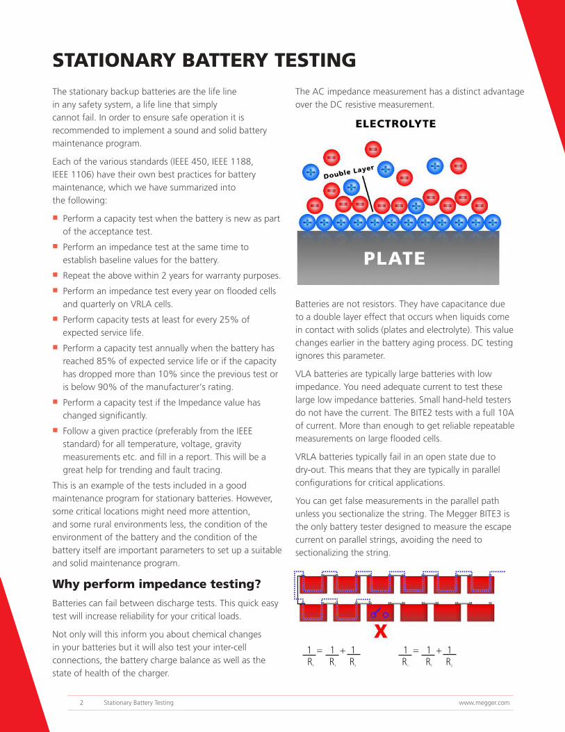
The AC impedance measurement has a distinct advantage over the DC resistive measurement.
Batteries are not resistors. They have capacitance due to a double layer effect that occurs when liquids come in contact with solids (plates and electrolyte). This value changes earlier in the battery aging process. DC testing ignores this parameter.
VLA batteries are typically large batteries with low impedance. You need adequate current to test these large low impedance batteries. Small hand-held testers do not have the current. The BITE2 tests with a full 10A of current. More than enough to get reliable repeatable measurements on large flooded cells.
VRLA batteries typically fail in an open state due to dry-out. This means that they are typically in parallel configurations for critical applications.
You can get false measurements in the parallel path unless you sectionalize the string. The Megger BITE3 is the only battery tester designed to measure the escape current on parallel strings, avoiding the need to sectionalizing the string.
1 = 1 + 1RT R1 R2
1 = 1 + 1R1 RT R2
2 Stationary Battery Testing www.megger.com
Why perform discharge testing?
Capacity test is the only way to get an accurate value on the actual capacity of the battery. When used regularly it can be used for tracking the battery’s health and actual capacity and estimate remaining life of the battery. During the test it is measured how much capacity (current x time expressed in Ah) the battery can deliver before the terminal voltage drops to the end of discharge voltage x number of cells. The current shall be maintained at a constant value. If the battery reaches the end of discharge voltage at the same time as the specified test time the battery’s actual capacity is 100% of the rated capacity. If it reaches the end of discharge at 80% (8 h) or before the specified 10 h, it shall be replaced.
It is important to measure the individual cell voltages. This has to be made a couple of times during the test. It is most important to measure the cells at the end of the discharge test in order to find the weak cells. It is also very important that the time OR the current during a discharge test is adjusted for the temperature of the battery. A cold battery will give less Ah than a warm one. Temperature correction factors and methods are described in the IEEE standards.
Batteries can also be tested at a shorter time than their duty cycle, for instance at 1 hour. Then the current rate has to be increased. The advantage is that less capacity is inconvenient and quite possibly very expensive in time, resources and money to rectify.
www.megger.com 3

■ Discharge testing for full insight into battery capacity
■ Enhanced safety features including spark free connection and emergency safety fuse
■ Ability to test the battery without disconnecting it from the system
■ High discharge capacity shortens the test time
■ A complete stand-alone discharge test system
Battery Load Unit
TORKEL900The TORKEL 900 series is used to perform load/discharge tests which are the only way to determine battery systems actual capacity. Together with the cell voltage logger, BVM, connected directly to the TORKEL 900, it becomes a complete, stand-alone, discharge test system.
TORKEL 930 is used for battery systems ranging from 12 to 300 V – often encountered in switchgear and similar equipment. The high discharge capacity of TORKEL gives the opportunity to shorten the test time. Discharging can take place at up to 220 A, and if higher current is needed, two or more TORKEL units or extra load units, TXL, can be linked together. Tests can be conducted at constant current, constant power, constant resistance or in accordance with a pre-selected load profile. Testing can be carried out without disconnecting the battery from the equipment it serves. Via a DC clamp-on ammeter, TORKEL measures total battery current while regulating it at a constant level.
TORKEL 910 is very much the same as the TORKEL 930 but has lower charging current and some other limitations. See table below.
MODEL OVERVIEW
Torkel 910 Torkel 930
Current (max)110A 220A
BVM functionality n
Charging measurement n
Full report functionalityn
4 Stationary Battery Testing www.megger.com

INCLUDED ACCESSORIES
Cables setsOPTIONAL ACCESSORIES
Extra loads
Cables
Sensing leads
Clamp-on-ammeters
TORKEL Viewer
Clamp-on ammeters, 200 A DC and 1000 A DC To measure current in circuit outside TORKEL
Cable set GA-00550 for TORKEL 910
Cable set GA-09550 for TORKEL 930
Three extra loads available: TXL830TXL850TXL870
Cable set (GA-00554)
Sensing lead set (GA-00210)
TORKEL Viewer can be used to edit and print out reports
www.megger.com 5

Battery Voltage Monitor
BVMThe Megger BVM is a battery voltage measurement device that is used for the capacity testing of large, industrial battery banks commonly found in electrical power substations, telecom facilities and computer data center UPS systems. When used in conjunction with a TORKEL unit and PowerDB and TORKEL Win, the BVM enables the TORKEL to perform a completely automated battery bank capacity test according to IEC test methods. The test also meets NERC/FERC requirements. The BVM is designed in modular form where one BVM device is used for each battery or “jar” in the string to be tested. One BVM for each battery connects to the next in a “daisy-chain” fashion, thereby providing easy and economical expandability to meet the testing requirements for small-to-large battery bank systems.
Setup is fast and easy using the BVM. Each BVM is identical and can be connected in any battery test position, thus providing maximum flexibility and interchangeability of the BVMs. Up to 120 BVMs can be daisy chained in a single battery bank under test. The BVM “Auto Discovery” feature enables the host device to automatically determine the number of batteries under test and provide sequential identification of each BVM in the test string.
■ Automates battery voltage measurement during capacity tests
■ Up to 2x120 units can be used (Daisy-chain)
6 Stationary Battery Testing www.megger.com

Bar Code Scanner: Scan your battery strings, no programming required.
Flex CT: Measure ripple currents around large buss bars.
Extension Probes: Ideal for those tight areas.
Hydrometer: Measure specific gravity of flooded cells and import directly into your Power DB database.
Mini CT: Measure ripple and test current in tight locations.
■ Determines condition of lead-acid and NiCD cells up to 7000 Ah
■ Tests large VLA batteries
■ On-board Pass/Warning/Fail indications
■ On-line testing
■ Checks charger condition by measuring ac ripple current
■ Includes Power DB LITE software
■ Measurements in 3 seconds
■ The perfect NERC Tool
Battery Impedance Tester
BITE®2, BITE®2PThe BITE2 and BITE2P Battery Impedance Test Equipment determines the condition of lead-acid and nickel-cadmium cells up to 7000 Ah. The BITE2 and 2P will measure changes in a battery’s internal chemistry due to aging effects. These effects can be caused by plate corrosion, plate shedding, plate sulfation, dry out, carbonation, negative plate depolarization and more.
The BITE2 and 2P test current supports testing of VLA batteries in addition to VRLA batteries.
The BITE2 and 2P has a measurement speed of 3 seconds per cell and per strap. This means faster testing. A built-in printer allows on site printing of recorded data.
The BITE2 and BITE2P are ideal for flooded lead acid batteries in substation applications.
Measures cell impedance, cell voltage, ripple current, terminal connection resistance, inter-cell resistance as well as string continuity, Inter-cell connections resistance, AC ripple.
BITE2P
BITE2
ACCESSORIES
www.megger.com 7

■ Determines health of lead-acid cells
■ Automatically detects cells and straps without programming
■ Test parallel strings without sectionalizing
■ Measures float current as well as ripple current.
■ Built in spectrum analyzer for locating faulty chargers.
■ View results on screen
Battery Impedance Tester
BITE®3
The BITE3 will measure changes in a battery’s internal chemistry due to aging effects. These effects can be caused by plate corrosion, plate shedding, plate sulfation, dry out, negative plate depolarization and more.
The BITE3’s auto cell strap detection means no complicated programming. Just enter a string name and the BITE3 does the rest. It tests parallel strings without the need of segmentation.
Kelvin Leads: Easily connect to terminal lugs.
Flex CT: Measures escape current on parallel strings. NO NEED TO SEGMENT
Lighted Extension Probes: Ideal for those tight dark areas.
Expanded Duplex Pistol Probes. Perfect for rooms with split battery strings. (6’ between pistols)
AC Power Supply. Operate your BITE3 off of an AC source.
ACCESSORIES
The BITE3 is ideal for parallel strings. It’s the perfect tool for telecom applications.
The BITE3 measures cell impedance, cell voltage, inter-cell connection resistance and ripple current. The BITE3 also measures float current. This allows you to detect conditions that can lead to a thermal runaway.
The built-in spectrum analyzer allows you to determine the source of the ripple current by examining its frequency.
The Current Transformer kit for the BITE 3 is for measuring the current in noisy battery systems and to measure “escape current” in parallel battery strings.
8 Stationary Battery Testing www.megger.com
Mini CT: Trace the faults in areas where the wiring is small and tight..
■ Easily locates ground faults up to 399kΩ in ungrounded dc systems
■ Operates in high electrical noise on line environment
■ High/low switch provides the needed power to locate high impedance faults
■ Characterize the resistance and capacitance of a fault
■ No wasted time tracing false paths
■ Operates on live battery systems (on line)
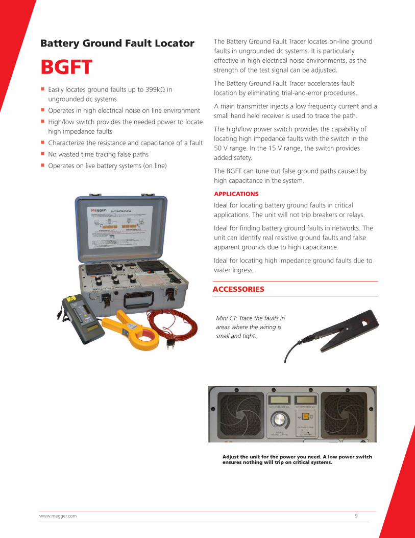
Battery Ground Fault Locator
BGFTThe Battery Ground Fault Tracer locates on-line ground faults in ungrounded dc systems. It is particularly effective in high electrical noise environments, as the strength of the test signal can be adjusted.
The Battery Ground Fault Tracer accelerates fault location by eliminating trial-and-error procedures.
A main transmitter injects a low frequency current and a small hand held receiver is used to trace the path.
The high/low power switch provides the capability of locating high impedance faults with the switch in the 50 V range. In the 15 V range, the switch provides added safety.
The BGFT can tune out false ground paths caused by high capacitance in the system.
APPLICATIONS
Ideal for locating battery ground faults in critical applications. The unit will not trip breakers or relays.
Ideal for finding battery ground faults in networks. The unit can identify real resistive ground faults and false apparent grounds due to high capacitance.
Ideal for locating high impedance ground faults due to water ingress.
ACCESSORIES
Adjust the unit for the power you need. A low power switch ensures nothing will trip on critical systems.
www.megger.com 9
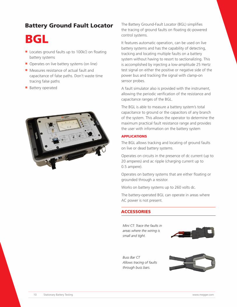
■ Locates ground faults up to 100kΩ on floating battery systems
■ Operates on live battery systems (on line)
■ Measures resistance of actual fault and capacitance of false paths. Don’t waste time tracing false paths
■ Battery operated
Battery Ground Fault Locator
BGLThe Battery Ground-Fault Locator (BGL) simplifies the tracing of ground faults on floating dc-powered control systems.
It features automatic operation, can be used on live battery systems and has the capability of detecting, tracking and locating multiple faults on a battery system without having to resort to sectionalizing. This is accomplished by injecting a low-amplitude 25 Hertz test signal on either the positive or negative side of the power bus and tracking the signal with clamp-on sensor probes.
A fault simulator also is provided with the instrument, allowing the periodic verification of the resistance and capacitance ranges of the BGL.
The BGL is able to measure a battery system’s total capacitance to ground or the capacitors of any branch of the system. This allows the operator to determine the maximum practical fault resistance range and provides the user with information on the battery system
APPLICATIONS
The BGL allows tracking and locating of ground faults on live or dead battery systems.
Operates on circuits in the presence of dc current (up to 20 amperes) and ac ripple (charging current up to 0.5 ampere).
Operates on battery systems that are either floating or grounded through a resistor.
Works on battery systems up to 260 volts dc.
The battery-operated BGL can operate in areas where AC power is not present.
Mini CT: Trace the faults in areas where the wiring is small and tight.
Buss Bar CT Allows tracing of faults through buss bars.
ACCESSORIES
10 Stationary Battery Testing www.megger.com

■ Database results
■ Trends battery data
■ Automatically calculates baselines data
■ Customize reports
■ Import hydrometer data
■ Have custom reports created for your needs
Software
POWER DBPower DB is a powerful software package that operates with the BITE2, BITE2P and BITE3. Power DB allows you to transfer and analyze data from the BITE units and create custom reports with your company’s logo. Trend voltages, impedances, strap resistances, cell temperature as well as specific gravity. Display the ripple current, float current, ambient temperature and calculate baseline data as well as having a location for a picture or diagram graphics.
Power DB comes in several versions including the freeware version DB LITE and the Power DB Pro version.
Data-basing battery data, performing trending analysis, merging hydrometer data.
IDEAL FOR NERC requirements!
www.megger.com 11

Battery_BR_US_V01The word ‘Megger’ is a registered trademarkCopyright © 2016 2621 Van Buren Ave Norristown, PA 19403