static stability assessment of an elcas(m) … · static stability assessment of an elcas(m) based...
TRANSCRIPT
ENGINEERING SERVICE CENTER Port Hueneme, California 93043-4370
Approved for public release; distribution is unlimited.
TECHNICAL MEMORANDUM
TM-2409-AMP
STATIC STABILITY ASSESSMENT OF AN ELCAS(M) BASED BARGE CRANE
By
Erick T. Huang
March 2009

ii
iii
REPORT DOCUMENTATION PAGE Form Approved
OMB No. 0704-0811 The public reporting burden for this collection of information is estimated to average 1 hour per response, including the time for reviewing instructions, searching existing data sources, gathering and maintaining the data needed, and completing and reviewing the collection of information. Send comments regarding this burden estimate or any other aspect of this collection of information, including suggestions for reducing the burden to Department of Defense, Washington Headquarters Services, Directorate for Information Operations and Reports (0704-0188), 1215 Jefferson Davis Highway, Suite 1204, Arlington, VA 22202-4302. Respondents should be aware that notwithstanding any other provision of law, no person shall be subject to any penalty for failing to comply with a collection of information, it if does not display a currently valid OMB control number.
PLEASE DO NOT RETURN YOUR FORM TO THE ABOVE ADDRESS. 1. REPORT DATE (DD-MM-YYYY) 2. REPORT TYPE 3. DATES COVERED (From – To)
4. TITLE AND SUBTITLE 5a. CONTRACT NUMBER
5b. GRANT NUMBER
5c. PROGRAM ELEMENT NUMBER
STATIC STABILITY ASSESSMENT OF AN ELCAS(M) BASED BARGE CRANE
6. AUTHOR(S) 5d. PROJECT NUMBER
5e. TASK NUMBER
5f. WORK UNIT NUMBER
Erick T. Huang
7. PERFORMING ORGANIZATION NAME(S) AND ADDRESSES 8. PERFORMING ORGANIZATION REPORT NUMBER
Commanding Officer Naval Facilities Engineering Service Center 1100 23rd Avenue Port Hueneme, CA 93043
TM-2409-AMP
9. SPONSORING/MONITORING AGENCY NAME(S) AND ADDRESS(ES) 10. SPONSOR/MONITORS ACRONYM(S)
11. SPONSOR/MONITOR’S REPORT NUMBER(S)
12. DISTRIBUTION/AVAILABILITY STATEMENT
Approved for public release; distribution is unlimited.
13. SUPPLEMENTARY NOTES
14. ABSTRACT This effort performs an engineering assessment to quantify the lift capacity of a temporary barge crane for cargo transfer in calm water at the waterfront. The assessment addresses two basic aspects concerning the effectiveness and operational safety of a barge crane: (a) the barge capacity to accommodate a mobile crane and (b) the crane boom capacity on a floating platform. Prospective barges were assessed for their capacity against capsizing in accordance with NAVFAC P-307 guidelines for floating derricks and the U.S. Navy’s wind heel criteria. This analysis determines the barge list in the worst-case cargo load scenario and thereby determines the range of machine list the crane incurs in service. The range of machine list is subsequently used to determine the allowable crane boom capacity from the manufacturer provided load chart for barge mounted crane installation. The results endorse a 3 by 7 ELCAS platform for the integration of the proposed barge crane. This effort further demonstrated that a criterion based on the maximum allowable barge list does not provide a full protection to the crane barge against capsizing without the evidence of sufficient reserve dynamic stability to withstand operational uncertainties or environmental anomalies. 15. SUBJECT TERMS barge crane, stability assessment, operational limits, pontoon barges 16. SECURITY CLASSIFICATION OF: 19a. NAME OF RESPONSIBLE PERSON a. REPORT b. ABSTRACT c. THIS PAGE
17. LIMITATION OF
ABSTRACT
18. NUMBER OF PAGES
19b. TELEPHONE NUMBER (include area code) U U U U 65
Standard Form 298 (Rev. 8/98) Prescribed by ANSI Std. Z39.18

iv
v
EXECUTIVE SUMMARY
OBJECTIVE
The objective of this study was to assess the static stability and thereby determine the operational limits of a proposed barge crane for cargo offloading at the waterfront.
OVERVIEW A temporary barge crane composed of a 200T Manitowoc Crawler Crane on the deck of an ELCAS(M) pontoon barge is to be used in JLOTS09. The operational scenario involves lifting fully laden 40-foot ISO containers (67 kips) from an INLS Causeway Ferry (CF) to shore. NAVFAC P-307 (Ref. 1) requires the performing activity to conduct a detailed assessment of the barge stability and reduce load charts for approval by a certifying official. NAVFAC Engineering Service Center (NAVFAC ESC) was tasked by NAVFAC Expeditionary Logistic Center (NAVFAC ELC) to assess the barge capacity of supporting the proposed crane installation for the intended operations. The assessment addresses two major issues concerning the effectiveness and safety of barge crane operations: (a) the barge capacity to accommodate a mobile crane on deck and (b) the ultimate crane boom capacity on a floating platform. Prospective barges were analyzed for their hydrostatic capacity against capsizing in accordance with NAVFAC P-307 guidelines for floating derricks and the U.S. Navy’s wind heel criteria. This analysis simulates the hydrostatic performance of the barge crane in the worst-case cargo load scenario and thereby determines the maximum machine list of the crane installation in service. The machine list is the key to determine the allowable boom capacity from the manufacturer provided load chart for the proposed crane installation.
CONCLUSIONS The proposed ELCAS platform of 3 modules long and 5 modules wide is unacceptable due to insufficient stability. The resulting barge crane installation is likely to capsize at the attempt to lift a fully laden 40-foot ISO container (67 kips) situated at the far edge of an INLS Causeway Ferry. A wider ELCAS platform of 3 modules long and 7 modules wide is required to support the proposed mobile crane for the intended cargo offloading mission. The resulting barge crane installation holds the barge list under the 3-degree limit imposed by NAVFAC P-307 guideline for floating derricks and provides sufficient reserve stability to absorb operational uncertainties and environmental anomalies in a supposedly calm water ambience. This barge crane installation restricts the maximum machine list to one degree throughout the entire cargo offloading cycle. This qualifies the crane installation to lift 67-kip ISO containers situated at the far edge of an INLS Causeway Ferry at 52 feet lift radius.
High center of gravity is the primary cause for capsizing a pontoon-based crane barge. Sheltered waters provide little margin in the scenario of heavy lifting with a long boom. A pontoon barge displays a high initial stiffness. However it capsizes very rapidly once its ultimate

vi
capacity is exceeded and leaves no time for remedial actions. Therefore, aggressive lift plans are not recommended.
A criterion based on the maximum heel angle does not provide a full protection to the barge crane against capsizing without the evidence of sufficient reserve dynamic stability to withstand operational uncertainties or environmental loads.
vii
TABLE OF CONTENTS
Page
INTRODUCTION..........................................................................................................................1 Objective ..............................................................................................................................1 Background..........................................................................................................................1 Scope of Analysis ................................................................................................................2
FEATURES OF PROPOSED BARGE CRANE ........................................................................5 ELCAS Barges.....................................................................................................................5 Mobile Crane .......................................................................................................................6 Key Parameters and Terminology ......................................................................................7
STABILITY NATURE OF A BARGE CRANE .......................................................................11 Geometry of ELCAS Barge ...............................................................................................11 Influences of Long Boom ................................................................................................13 Stability Criteria for Pontoon Barges.................................................................................13 STATIC STABILITY ANALYSIS ............................................................................................16 Analytical Model ..............................................................................................................16 Stability Curves of the Candidate Barges in Lightship Condition ....................................18 Performance of the Candidate Barges in Operational Condition.......................................19 Influences of Crane Weight Distribution...........................................................................24
SUMMARY ..................................................................................................................................29
CONCLUSIONS ..........................................................................................................................33
REFERENCES.............................................................................................................................33

viii
ix
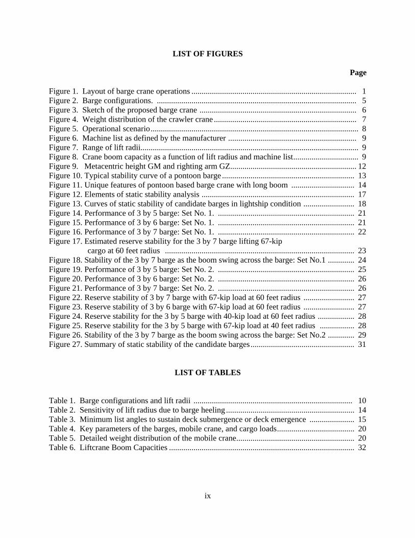
LIST OF FIGURES
Page
Figure 1. Layout of barge crane operations ................................................................................. 1 Figure 2. Barge configurations. .................................................................................................. 5 Figure 3. Sketch of the proposed barge crane ............................................................................. 6 Figure 4. Weight distribution of the crawler crane ...................................................................... 7 Figure 5. Operational scenario...................................................................................................... 8 Figure 6. Machine list as defined by the manufacturer ............................................................... 9 Figure 7. Range of lift radii........................................................................................................... 9 Figure 8. Crane boom capacity as a function of lift radius and machine list................................ 9 Figure 9. Metacentric height GM and righting arm GZ.............................................................. 12 Figure 10. Typical stability curve of a pontoon barge ................................................................. 13 Figure 11. Unique features of pontoon based barge crane with long boom ............................... 14 Figure 12. Elements of static stability analysis ........................................................................... 17 Figure 13. Curves of static stability of candidate barges in lightship condition ......................... 18 Figure 14. Performance of 3 by 5 barge: Set No. 1. ................................................................... 21 Figure 15. Performance of 3 by 6 barge: Set No. 1. ................................................................... 21 Figure 16. Performance of 3 by 7 barge: Set No. 1. ................................................................... 22 Figure 17. Estimated reserve stability for the 3 by 7 barge lifting 67-kip cargo at 60 feet radius ............................................................................................. 23 Figure 18. Stability of the 3 by 7 barge as the boom swing across the barge: Set No.1 ............. 24 Figure 19. Performance of 3 by 5 barge: Set No. 2. ................................................................... 25 Figure 20. Performance of 3 by 6 barge: Set No. 2. ................................................................... 26 Figure 21. Performance of 3 by 7 barge: Set No. 2. ................................................................... 26 Figure 22. Reserve stability of 3 by 7 barge with 67-kip load at 60 feet radius ......................... 27 Figure 23. Reserve stability of 3 by 6 barge with 67-kip load at 60 feet radius ......................... 27 Figure 24. Reserve stability for the 3 by 5 barge with 40-kip load at 60 feet radius .................. 28 Figure 25. Reserve stability for the 3 by 5 barge with 67-kip load at 40 feet radius ................. 28 Figure 26. Stability of the 3 by 7 barge as the boom swing across the barge: Set No.2 ............. 29 Figure 27. Summary of static stability of the candidate barges................................................... 31
LIST OF TABLES Table 1. Barge configurations and lift radii .............................................................................. 10 Table 2. Sensitivity of lift radius due to barge heeling ............................................................... 14 Table 3. Minimum list angles to sustain deck submergence or deck emergence ...................... 15 Table 4. Key parameters of the barges, mobile crane, and cargo loads...................................... 20 Table 5. Detailed weight distribution of the mobile crane.......................................................... 20 Table 6. Liftcrane Boom Capacities ........................................................................................... 32

x
1
INTRODUCTION
Objective The objective of this study was to assess the static stability and thereby determine the
operational limits of a proposed barge crane for cargo offloading at the waterfront.
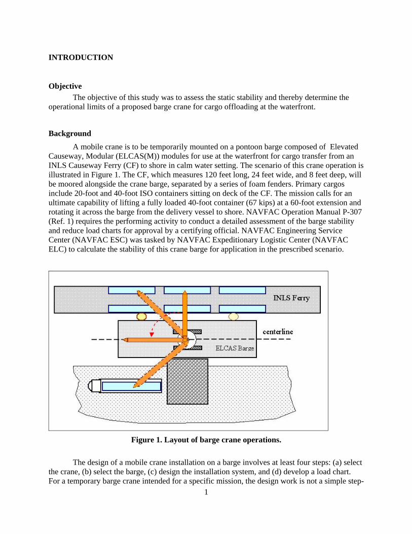
Background A mobile crane is to be temporarily mounted on a pontoon barge composed of Elevated Causeway, Modular (ELCAS(M)) modules for use at the waterfront for cargo transfer from an INLS Causeway Ferry (CF) to shore in calm water setting. The scenario of this crane operation is illustrated in Figure 1. The CF, which measures 120 feet long, 24 feet wide, and 8 feet deep, will be moored alongside the crane barge, separated by a series of foam fenders. Primary cargos include 20-foot and 40-foot ISO containers sitting on deck of the CF. The mission calls for an ultimate capability of lifting a fully loaded 40-foot container (67 kips) at a 60-foot extension and rotating it across the barge from the delivery vessel to shore. NAVFAC Operation Manual P-307 (Ref. 1) requires the performing activity to conduct a detailed assessment of the barge stability and reduce load charts for approval by a certifying official. NAVFAC Engineering Service Center (NAVFAC ESC) was tasked by NAVFAC Expeditionary Logistic Center (NAVFAC ELC) to calculate the stability of this crane barge for application in the prescribed scenario.
Figure 1. Layout of barge crane operations.
The design of a mobile crane installation on a barge involves at least four steps: (a) select the crane, (b) select the barge, (c) design the installation system, and (d) develop a load chart. For a temporary barge crane intended for a specific mission, the design work is not a simple step-
2
by-step process. The effort often requires iterations of estimate and revision, as the performance of a mobile crane is highly dependent on the hydrodynamic performance of the supporting barge. A 200T Manitowoc Crawler Crane of Model 777 Series 2 fitted with a #78 heavy lift boom of 130 feet length was provided by the sponsor as an initial candidate for the prescribed operation. This task proceeds to the task of barge selection on the assumption that the crane is to be rigidly mounted to the barge deck. This implies that the crane is restrained from tipping and that all overturning moments imposed by the crane and lift cargo will be entirely transferred to the barge. Findings of this analysis will be used to review the crane boom capacity and to assist the development of a load chart.
Scope of Analysis This effort explored the static stability of a proposed barge crane to be used for transferring cargo at the waterfront. Three candidate configurations of the ELCAS(M) pontoon barges of 40 feet, 48 feet, and 56 feet wide by 120 feet long were assessed for their capacities to accommodate a 200T Manitowoc Crawler Crane for use within prescribed lifting conditions.
Stability of a vessel is customarily presented via a static stability curve, which describes the overturning moments required to incline a vessel to various attitudes for a given loading condition. This curve is in essence a load-deflection curve of a mechanical system and normally presented in terms of righting arm versus angles of vessel inclination. It constitutes the base of traditional ship stability criteria. Existing safety regulations thereby set thresholds in terms of the minimum righting arm and the minimum reserve stability for a vessel.
This study generated a complete set of the curves of static stability of the supporting barge in both lightship and service conditions. These curves were subsequently used to evaluate the barge stability against capsizing based on documented stability criteria for floating derricks, including the operational requirements cited in NAVFAC P-307 and ANSI B30.8 (Ref. 2), enhanced by the Navy’s wind heel criteria (Ref. 3) for conventional hulls.
One key factor, which critically influences the results of stability analysis, is the weight distribution of the crawler crane in use. The initial instructions from the sponsor treat the crane weight in two parts. One associates to the crane boom and the other associates with the crane base including the rest of the upperworks and the entire lowerworks. The entire weight of the crane base is posted in line with it center of rotation. The offsets of the heavy counterweights are ignored. These assumptions lead to a conservative estimate of the barge stability. The sequence of stability analysis under these assumptions of simplified crane weight distributions will be referred as Set No. 1. A second sequence of simulation reiterates the computations to explore the influence of the counterweights. The results are referred as Set No. 2. In Set No. 2, the weight of the crane base is further distributed to the centers of gravity associated with the upperworks and the lowerworks whereas the weight of the crane boom is distributed to its ends according to the manufacturer’s product guide1 (Ref. 4). Consequently, the upperworks and the boom rotate simultaneously and thus properly allocate the true weight distribution at a specific boom heading. The results of analysis, significant findings, and recommendations were documented in this report and the database generated is archived to a reliable electronic storage.
1 A later communication with the manufacturer indicated that the weight distribution in the product guide is slightly different than the actual measurements for Model 777 Series 2.
3
This task only addresses the stability of the proposed crane barge against capsizing in the prescribed service conditions. It is assumed that the mobile crane is positively secured to the barge deck and the deck is structurally sound to hold the crane in service. As such, overturning moments imposed by the crane and lifted cargos are fully transferred to the supporting barge.
Note that the stability against capsizing alone does not endorse a safe operation and lift capacity of the barge crane as the crane has its own limitations. The capacity of a crane barge is established through a load chart as required by NAVFAC P-307. The effort of generating the required load chart is beyond the scope of this task and requires detailed knowledge of the crane design and functional limits. This is normally a joint effort involving field operators, manufacturers, and analysts with marine and structural expertise.

4
5
FEATURES OF PROPOSED BARGE CRANE
ELCAS Barges The proposed barge to support the mobile crane is fabricated from ELCAS(M) pontoons
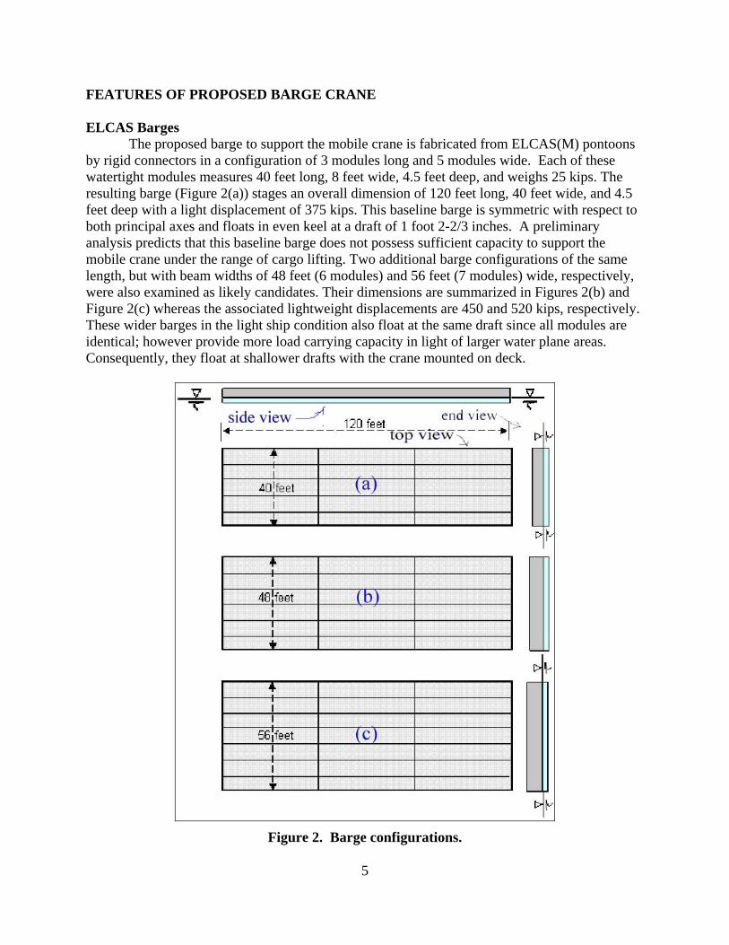
by rigid connectors in a configuration of 3 modules long and 5 modules wide. Each of these watertight modules measures 40 feet long, 8 feet wide, 4.5 feet deep, and weighs 25 kips. The resulting barge (Figure 2(a)) stages an overall dimension of 120 feet long, 40 feet wide, and 4.5 feet deep with a light displacement of 375 kips. This baseline barge is symmetric with respect to both principal axes and floats in even keel at a draft of 1 foot 2-2/3 inches. A preliminary analysis predicts that this baseline barge does not possess sufficient capacity to support the mobile crane under the range of cargo lifting. Two additional barge configurations of the same length, but with beam widths of 48 feet (6 modules) and 56 feet (7 modules) wide, respectively, were also examined as likely candidates. Their dimensions are summarized in Figures 2(b) and Figure 2(c) whereas the associated lightweight displacements are 450 and 520 kips, respectively. These wider barges in the light ship condition also float at the same draft since all modules are identical; however provide more load carrying capacity in light of larger water plane areas. Consequently, they float at shallower drafts with the crane mounted on deck.
Figure 2. Barge configurations.
6
Mobile Crane
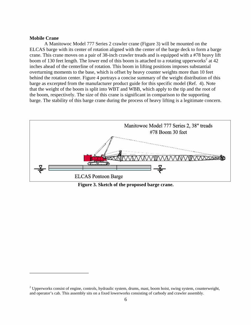
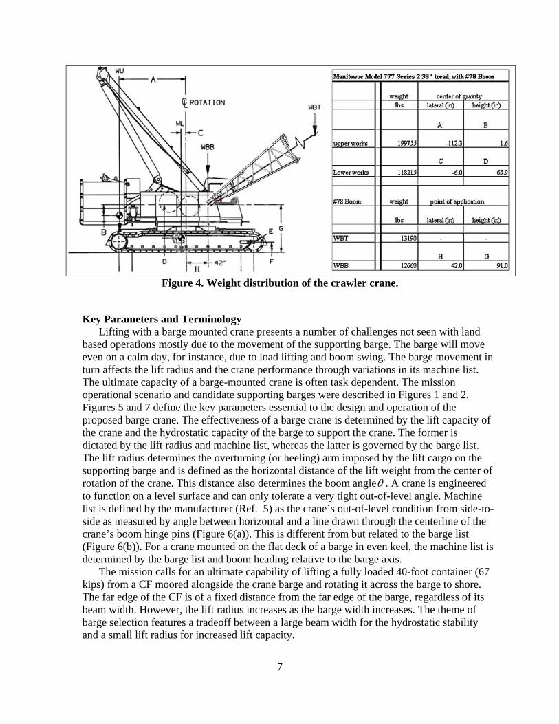
A Manitowoc Model 777 Series 2 crawler crane (Figure 3) will be mounted on the ELCAS barge with its center of rotation aligned with the center of the barge deck to form a barge crane. This crane moves on a pair of 38-inch crawler treads and is equipped with a #78 heavy lift boom of 130 feet length. The lower end of this boom is attached to a rotating upperworks2 at 42 inches ahead of the centerline of rotation. This boom in lifting positions imposes substantial overturning moments to the base, which is offset by heavy counter weights more than 10 feet behind the rotation center. Figure 4 portrays a concise summary of the weight distribution of this barge as excerpted from the manufacturer product guide for this specific model (Ref. 4). Note that the weight of the boom is split into WBT and WBB, which apply to the tip and the root of the boom, respectively. The size of this crane is significant in comparison to the supporting barge. The stability of this barge crane during the process of heavy lifting is a legitimate concern.
Figure 3. Sketch of the proposed barge crane.
2 Upperworks consist of engine, controls, hydraulic system, drums, mast, boom hoist, swing system, counterweight, and operator’s cab. This assembly sits on a fixed lowerworks consisting of carbody and crawler assembly.
7
Figure 4. Weight distribution of the crawler crane.
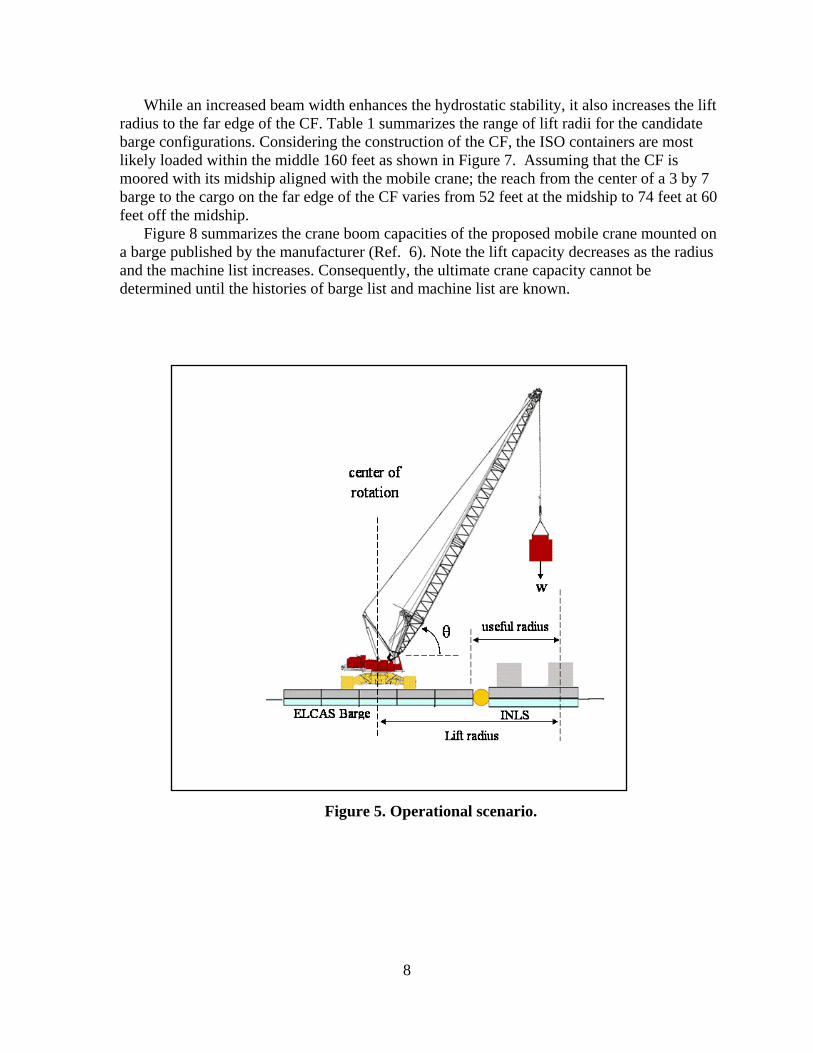
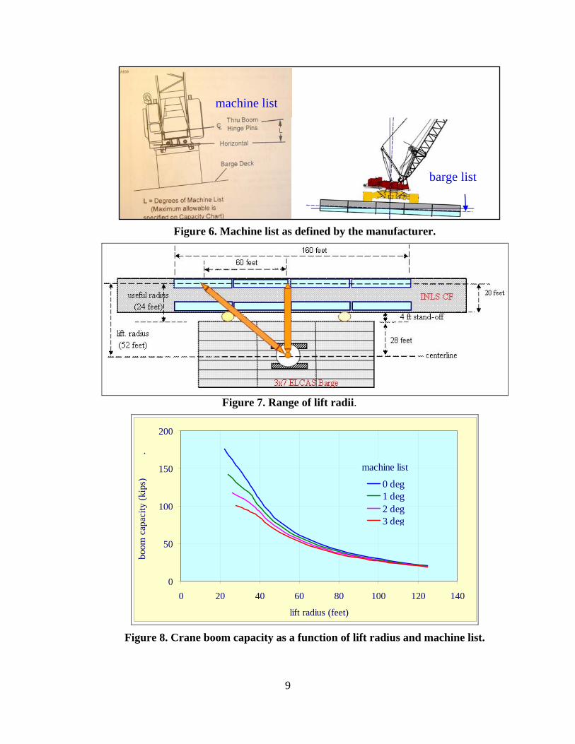
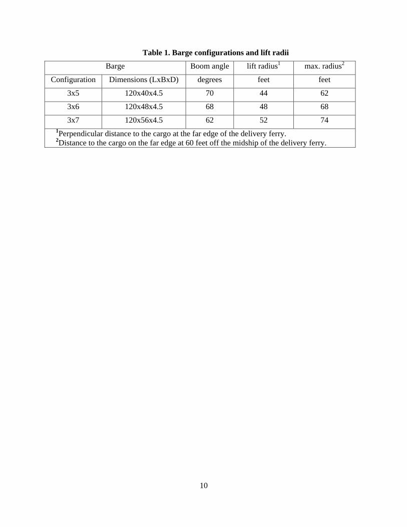
Key Parameters and Terminology Lifting with a barge mounted crane presents a number of challenges not seen with land based operations mostly due to the movement of the supporting barge. The barge will move even on a calm day, for instance, due to load lifting and boom swing. The barge movement in turn affects the lift radius and the crane performance through variations in its machine list. The ultimate capacity of a barge-mounted crane is often task dependent. The mission operational scenario and candidate supporting barges were described in Figures 1 and 2. Figures 5 and 7 define the key parameters essential to the design and operation of the proposed barge crane. The effectiveness of a barge crane is determined by the lift capacity of the crane and the hydrostatic capacity of the barge to support the crane. The former is dictated by the lift radius and machine list, whereas the latter is governed by the barge list. The lift radius determines the overturning (or heeling) arm imposed by the lift cargo on the supporting barge and is defined as the horizontal distance of the lift weight from the center of rotation of the crane. This distance also determines the boom angleθ . A crane is engineered to function on a level surface and can only tolerate a very tight out-of-level angle. Machine list is defined by the manufacturer (Ref. 5) as the crane’s out-of-level condition from side-to-side as measured by angle between horizontal and a line drawn through the centerline of the crane’s boom hinge pins (Figure 6(a)). This is different from but related to the barge list (Figure 6(b)). For a crane mounted on the flat deck of a barge in even keel, the machine list is determined by the barge list and boom heading relative to the barge axis. The mission calls for an ultimate capability of lifting a fully loaded 40-foot container (67 kips) from a CF moored alongside the crane barge and rotating it across the barge to shore. The far edge of the CF is of a fixed distance from the far edge of the barge, regardless of its beam width. However, the lift radius increases as the barge width increases. The theme of barge selection features a tradeoff between a large beam width for the hydrostatic stability and a small lift radius for increased lift capacity.
8
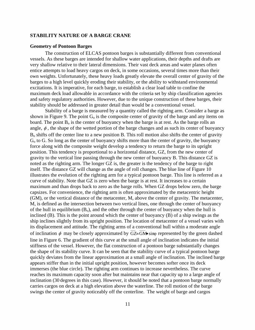
While an increased beam width enhances the hydrostatic stability, it also increases the lift radius to the far edge of the CF. Table 1 summarizes the range of lift radii for the candidate barge configurations. Considering the construction of the CF, the ISO containers are most likely loaded within the middle 160 feet as shown in Figure 7. Assuming that the CF is moored with its midship aligned with the mobile crane; the reach from the center of a 3 by 7 barge to the cargo on the far edge of the CF varies from 52 feet at the midship to 74 feet at 60 feet off the midship. Figure 8 summarizes the crane boom capacities of the proposed mobile crane mounted on a barge published by the manufacturer (Ref. 6). Note the lift capacity decreases as the radius and the machine list increases. Consequently, the ultimate crane capacity cannot be determined until the histories of barge list and machine list are known.
Figure 5. Operational scenario.
9
machine list
barge list
Figure 6. Machine list as defined by the manufacturer.
Figure 7. Range of lift radii.
0
50
100
150
200
0 20 40 60 80 100 120 140
lift radius (feet)
boom
cap
acity
(kip
s)
.
0 deg1 deg2 deg3 deg
machine list
Figure 8. Crane boom capacity as a function of lift radius and machine list.
10
Table 1. Barge configurations and lift radii
Barge Boom angle lift radius1 max. radius2
Configuration Dimensions (LxBxD) degrees feet feet
3x5 120x40x4.5 70 44 62
3x6 120x48x4.5 68 48 68
3x7 120x56x4.5 62 52 74 1Perpendicular distance to the cargo at the far edge of the delivery ferry. 2Distance to the cargo on the far edge at 60 feet off the midship of the delivery ferry.
11
STABILITY NATURE OF A BARGE CRANE
Geometry of Pontoon Barges The construction of ELCAS pontoon barges is substantially different from conventional
vessels. As these barges are intended for shallow water applications, their depths and drafts are very shallow relative to their lateral dimensions. Their vast deck areas and water planes often entice attempts to load heavy cargos on deck, in some occasions, several times more than their own weights. Unfortunately, these heavy loads greatly elevate the overall center of gravity of the barges to a high level quickly eroding their stability, or the ability to withstand environmental excitations. It is imperative, for each barge, to establish a clear load table to confine the maximum deck load allowable in accordance with the criteria set by ship classification agencies and safety regulatory authorities. However, due to the unique construction of these barges, their stability should be addressed in greater detail than would be a conventional vessel.
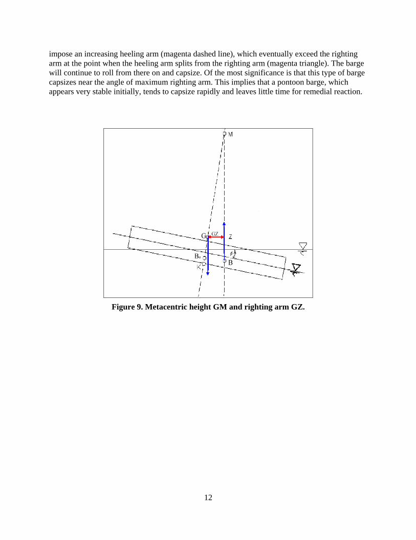
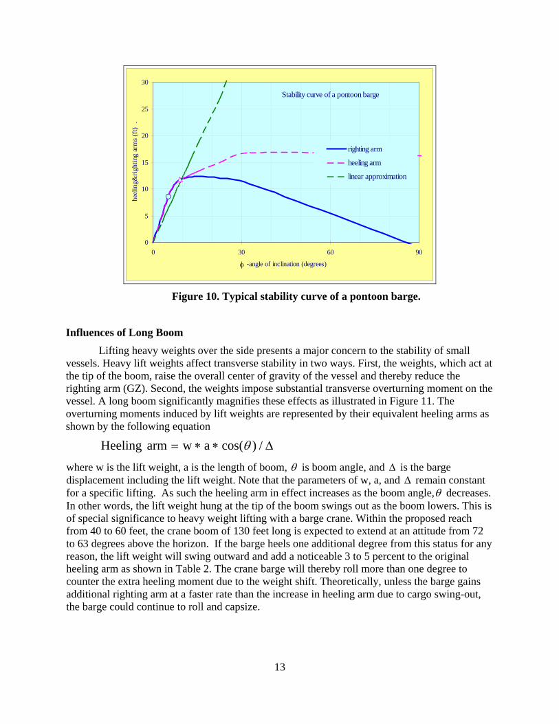
Stability of a barge is measured by a quantity called the righting arm. Consider a barge as shown in Figure 9. The point Go is the composite center of gravity of the barge and any items on board. The point Bo is the center of buoyancy when the barge is at rest. As the barge rolls an angle, φ , the shape of the wetted portion of the barge changes and as such its center of buoyancy Bo shifts off the center line to a new position B. This roll motion also shifts the center of gravity Go to G. So long as the center of buoyancy shifts more than the center of gravity, the buoyancy force along with the composite weight develop a tendency to return the barge to its upright position. This tendency is proportional to a horizontal distance, GZ, from the new center of gravity to the vertical line passing through the new center of buoyancy B. This distance GZ is noted as the righting arm. The longer GZ is, the greater is the tendency of the barge to right itself. The distance GZ will change as the angle of roll changes. The blue line of Figure 10 illustrates the evolution of the righting arm for a typical pontoon barge. This line is referred as a curve of stability. Note that GZ is zero when the barge is at rest. It increases to a certain maximum and than drops back to zero as the barge rolls. When GZ drops below zero, the barge capsizes. For convenience, the righting arm is often approximated by the metacentric height (GM), or the vertical distance of the metacenter, M, above the center of gravity. The metacenter, M, is defined as the intersection between two vertical lines, one through the center of buoyancy of the hull in equilibrium (Bo), and the other through the center of buoyancy when the hull is inclined (B). This is the point around which the center of buoyancy (B) of a ship swings as the ship inclines slightly from its upright position. The location of metacenter of a vessel varies with its displacement and attitude. The righting arms of a conventional hull within a moderate angle of inclination φ may be closely approximated by φsinGMGZ •≈ represented by the green dashed line in Figure 6. The gradient of this curve at the small angle of inclination indicates the initial stiffness of the vessel. However, the flat construction of a pontoon barge substantially changes the shape of its stability curve. It can be seen that the stability curve of a typical pontoon barge quickly deviates from the linear approximation at a small angle of inclination. The inclined barge appears stiffer than in the initial upright position, however becomes softer once its deck immerses (the blue circle). The righting arm continues to increase nevertheless. The curve reaches its maximum capacity soon after but maintains near that capacity up to a large angle of inclination (30 degrees in this case). However, it should be noted that a pontoon barge normally carries cargos on deck at a high elevation above the waterline. The roll motion of the barge swings the center of gravity noticeably off the centerline. The weight of barge and cargos
12
impose an increasing heeling arm (magenta dashed line), which eventually exceed the righting arm at the point when the heeling arm splits from the righting arm (magenta triangle). The barge will continue to roll from there on and capsize. Of the most significance is that this type of barge capsizes near the angle of maximum righting arm. This implies that a pontoon barge, which appears very stable initially, tends to capsize rapidly and leaves little time for remedial reaction.
Figure 9. Metacentric height GM and righting arm GZ.
13
0
5
10
15
20
25
30
0 30 60 90
-angle of inclination (degrees)
heel
ing&
right
ing
arm
s (ft)
.
righting arm
heeling arm
linear approximation
Stability curve of a pontoon barge
φ
Figure 10. Typical stability curve of a pontoon barge.
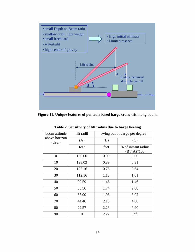
Influences of Long Boom Lifting heavy weights over the side presents a major concern to the stability of small
vessels. Heavy lift weights affect transverse stability in two ways. First, the weights, which act at the tip of the boom, raise the overall center of gravity of the vessel and thereby reduce the righting arm (GZ). Second, the weights impose substantial transverse overturning moment on the vessel. A long boom significantly magnifies these effects as illustrated in Figure 11. The overturning moments induced by lift weights are represented by their equivalent heeling arms as shown by the following equation
Δ∗∗= /)cos(awarmHeeling θ
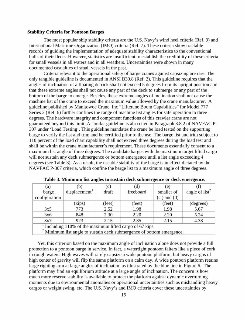
where w is the lift weight, a is the length of boom, θ is boom angle, and Δ is the barge displacement including the lift weight. Note that the parameters of w, a, and Δ remain constant for a specific lifting. As such the heeling arm in effect increases as the boom angle,θ decreases. In other words, the lift weight hung at the tip of the boom swings out as the boom lowers. This is of special significance to heavy weight lifting with a barge crane. Within the proposed reach from 40 to 60 feet, the crane boom of 130 feet long is expected to extend at an attitude from 72 to 63 degrees above the horizon. If the barge heels one additional degree from this status for any reason, the lift weight will swing outward and add a noticeable 3 to 5 percent to the original heeling arm as shown in Table 2. The crane barge will thereby roll more than one degree to counter the extra heeling moment due to the weight shift. Theoretically, unless the barge gains additional righting arm at a faster rate than the increase in heeling arm due to cargo swing-out, the barge could continue to roll and capsize.
14
Lift radius
• small Depth-to-Beam ratio• shallow draft: light weight• small freeboard• watertight• high center of gravity
Radius increment due to barge roll
• High initial stiffness• Limited reserve
θ
Figure 11. Unique features of pontoon based barge crane with long boom.
Table 2. Sensitivity of lift radius due to barge heeling
lift radii swing out of cargo per degree
(A) (B) (C)
boom attitude above horizon
(deg.) feet feet % of instant radius
(B)/(A)*100 0 130.00 0.00 0.00
10 128.03 0.39 0.31
20 122.16 0.78 0.64
30 112.16 1.13 1.01
40 99.59 1.46 1.46
50 83.56 1.74 2.08
60 65.00 1.96 3.02
70 44.46 2.13 4.80
80 22.57 2.23 9.90
90 0 2.27 Inf.
15
Stability Criteria for Pontoon Barges The most popular ship stability criteria are the U.S. Navy’s wind heel criteria (Ref. 3) and
International Maritime Organization (IMO) criteria (Ref. 7). These criteria show tractable records of guiding the implementation of adequate stability characteristics to the conventional hulls of their fleets. However, statistics are insufficient to establish the credibility of these criteria for small vessels in all waters and in all weathers. Uncertainties were shown in many documented casualties of small vessels in the past.
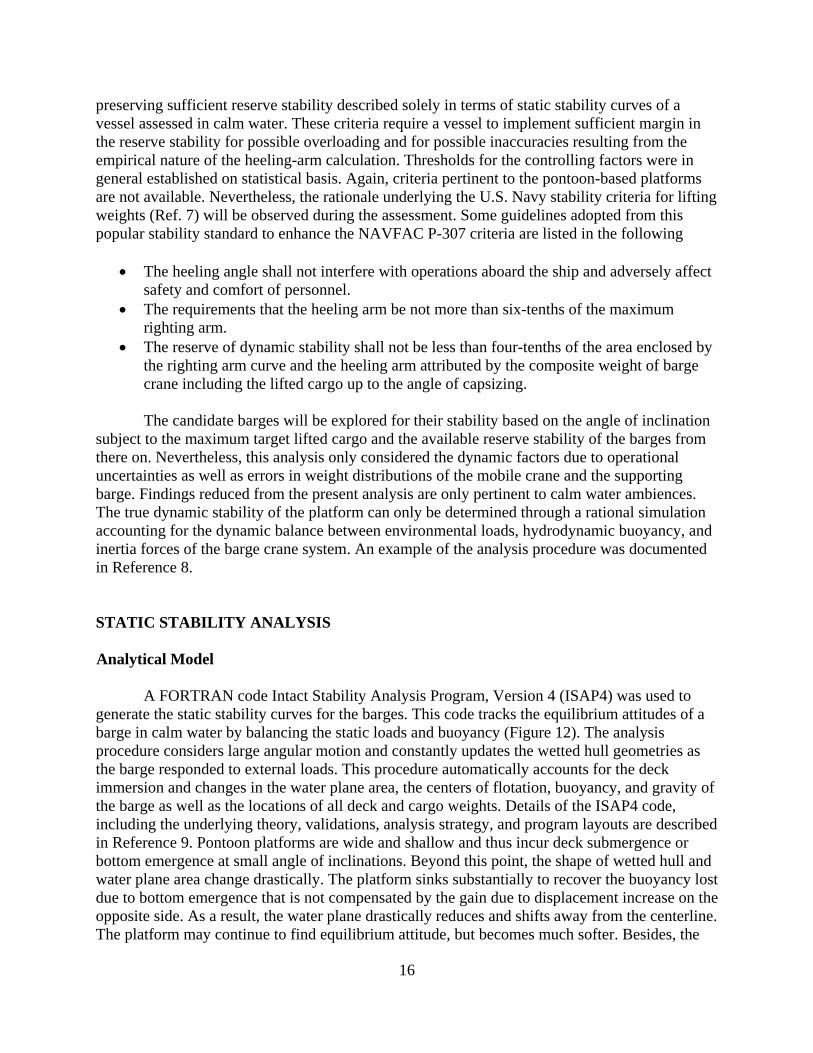
Criteria relevant to the operational safety of barge cranes against capsizing are rare. The only tangible guideline is documented in ANSI B30.8 (Ref. 2). This guideline requires that the angles of inclination of a floating derrick shall not exceed 5 degrees from its upright position and that these extreme angles shall not cause any part of the deck to submerge or any part of the bottom of the barge to emerge. Besides, these extreme angles of inclination shall not cause the machine list of the crane to exceed the maximum value allowed by the crane manufacturer. A guideline published by Manitowoc Crane, Inc “Liftcrane Boom Capabilities” for Model 777 Series 2 (Ref. 6) further confines the range of machine list angles for safe operation to three degrees. The hardware integrity and component functions of this crawler crane are not guaranteed beyond this limit. A similar guideline is also cited in Paragraph 3.8.2 of NAVFAC P-307 under ‘Load Testing’. This guideline mandates the crane be load tested on the supporting barge to verify the list and trim and be certified prior to the use. The barge list and trim subject to 110 percent of the load chart capability shall not exceed three degrees during the load test and shall be within the crane manufacturer’s requirement. These documents essentially consent to a maximum list angle of three degrees. The candidate barges with the maximum target lifted cargo will not sustain any deck submergence or bottom emergence until a list angle exceeding 4 degrees (see Table 3). As a result, the useable stability of the barge is in effect dictated by the NAVFAC P-307 criteria, which confine the barge list to a maximum angle of three degrees.
Table 3. Minimum list angles to sustain deck submergence or deck emergence. (a)
barge configuration
(b) displacement1
(c) draft
(d) freeboard
(e) smaller of (c ) and (d)
(f) angle of list2
(kips) (feet) (feet) (feet) (degrees) 3x5 773 2.52 1.98 1.98 5.67 3x6 848 2.30 2.20 2.20 5.24 3x7 923 2.15 2.35 2.15 4.38
1 Including 110% of the maximum lifted cargo of 67 kips. 2 Minimum list angle to sustain deck submergence of bottom emergence.
Yet, this criterion based on the maximum angle of inclination alone does not provide a full
protection to a pontoon barge in service. In fact, a watertight pontoon falters like a piece of cork in rough waters. High waves will rarely capsize a wide pontoon platform; but heavy cargos of high center of gravity will flip the same platform on a calm day. A wide pontoon platform retains large righting arm at large angles of inclination as illustrated by the blue line in Figure 6. The platform may find an equilibrium attitude at a large angle of inclination. The concern is how much more reserve stability is available to protect the platform against dynamic overturning moments due to environmental anomalies or operational uncertainties such as mishandling heavy cargos or weight swing, etc. The U.S. Navy’s and IMO criteria cover these uncertainties by
16
preserving sufficient reserve stability described solely in terms of static stability curves of a vessel assessed in calm water. These criteria require a vessel to implement sufficient margin in the reserve stability for possible overloading and for possible inaccuracies resulting from the empirical nature of the heeling-arm calculation. Thresholds for the controlling factors were in general established on statistical basis. Again, criteria pertinent to the pontoon-based platforms are not available. Nevertheless, the rationale underlying the U.S. Navy stability criteria for lifting weights (Ref. 7) will be observed during the assessment. Some guidelines adopted from this popular stability standard to enhance the NAVFAC P-307 criteria are listed in the following
• The heeling angle shall not interfere with operations aboard the ship and adversely affect
safety and comfort of personnel. • The requirements that the heeling arm be not more than six-tenths of the maximum
righting arm. • The reserve of dynamic stability shall not be less than four-tenths of the area enclosed by
the righting arm curve and the heeling arm attributed by the composite weight of barge crane including the lifted cargo up to the angle of capsizing.
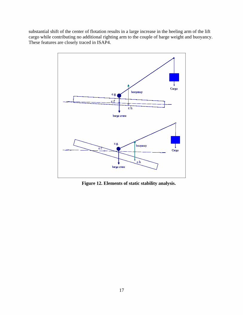
The candidate barges will be explored for their stability based on the angle of inclination subject to the maximum target lifted cargo and the available reserve stability of the barges from there on. Nevertheless, this analysis only considered the dynamic factors due to operational uncertainties as well as errors in weight distributions of the mobile crane and the supporting barge. Findings reduced from the present analysis are only pertinent to calm water ambiences. The true dynamic stability of the platform can only be determined through a rational simulation accounting for the dynamic balance between environmental loads, hydrodynamic buoyancy, and inertia forces of the barge crane system. An example of the analysis procedure was documented in Reference 8. STATIC STABILITY ANALYSIS Analytical Model
A FORTRAN code Intact Stability Analysis Program, Version 4 (ISAP4) was used to generate the static stability curves for the barges. This code tracks the equilibrium attitudes of a barge in calm water by balancing the static loads and buoyancy (Figure 12). The analysis procedure considers large angular motion and constantly updates the wetted hull geometries as the barge responded to external loads. This procedure automatically accounts for the deck immersion and changes in the water plane area, the centers of flotation, buoyancy, and gravity of the barge as well as the locations of all deck and cargo weights. Details of the ISAP4 code, including the underlying theory, validations, analysis strategy, and program layouts are described in Reference 9. Pontoon platforms are wide and shallow and thus incur deck submergence or bottom emergence at small angle of inclinations. Beyond this point, the shape of wetted hull and water plane area change drastically. The platform sinks substantially to recover the buoyancy lost due to bottom emergence that is not compensated by the gain due to displacement increase on the opposite side. As a result, the water plane drastically reduces and shifts away from the centerline. The platform may continue to find equilibrium attitude, but becomes much softer. Besides, the
17
substantial shift of the center of flotation results in a large increase in the heeling arm of the lift cargo while contributing no additional righting arm to the couple of barge weight and buoyancy. These features are closely traced in ISAP4.
Figure 12. Elements of static stability analysis.
18
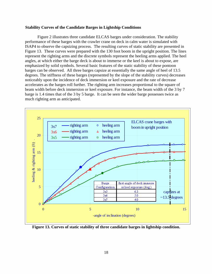
Stability Curves of the Candidate Barges in Lightship Conditions
Figure 2 illustrates three candidate ELCAS barges under consideration. The stability performance of these barges with the crawler crane on deck in calm water is simulated with ISAP4 to observe the capsizing process. The resulting curves of static stability are presented in Figure 13. These curves were prepared with the 130 foot boom in the upright position. The lines represent the righting arms and the discrete symbols represent the heeling arms applied. The heel angles, at which either the barge deck is about to immerse or the keel is about to expose, are emphasized by solid symbols. Several basic features of the static stability of these pontoon barges can be observed. All three barges capsize at essentially the same angle of heel of 13.5 degrees. The stiffness of these barges (represented by the slope of the stability curves) decreases noticeably upon the incidence of deck immersion or keel exposure and the rate of decrease accelerates as the barges roll further. The righting arm increases proportional to the square of beam width before deck immersion or keel exposure. For instance, the beam width of the 3 by 7 barge is 1.4 times that of the 3 by 5 barge. It can be seen the wider barge possesses twice as much righting arm as anticipated.
0
5
10
15
20
25
0 5 10 15
-angle of inclination (degrees)
heel
ing
& ri
ghtin
g ar
m (f
t) .
righting arm heeling armrighting arm heeling armrighting arm heeling arm
capsizes at ~13.5 degrees
ELCAS crane barges with boom in upright position3x7
3x63x5
Figure 13. Curves of static stability of three candidate barges in lightship condition.
19
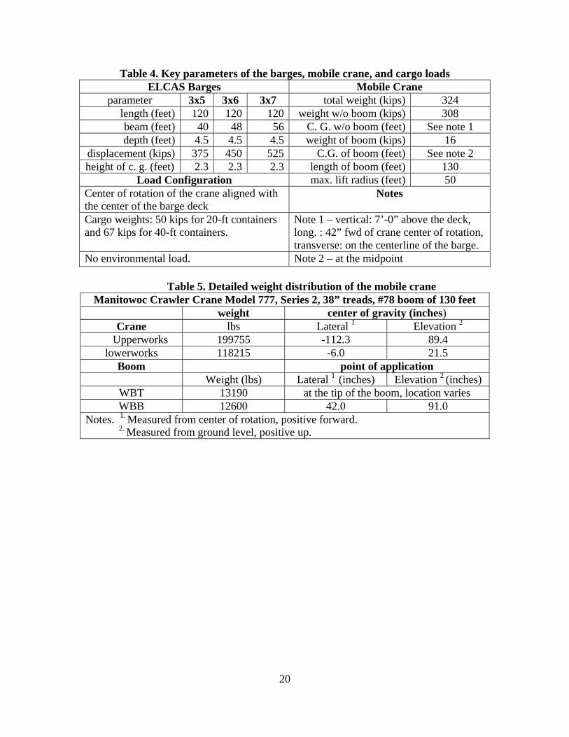
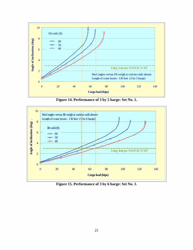
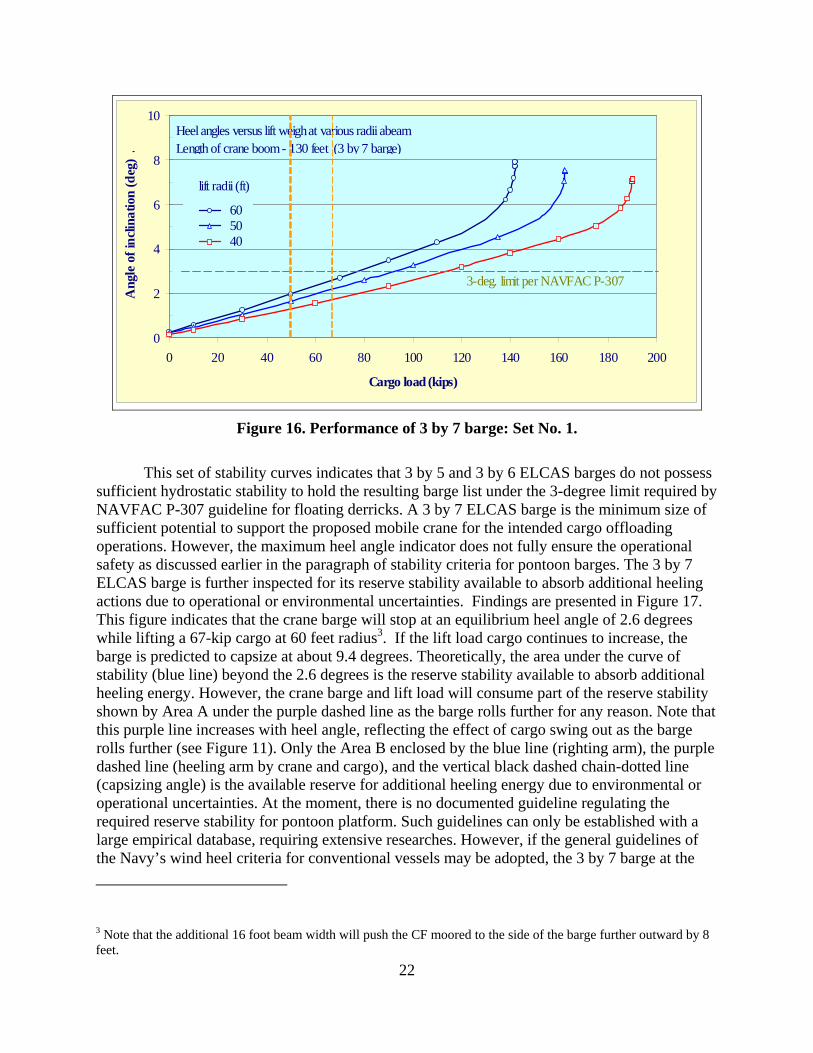
Performance of the Candidate Barges in Operational Conditions The hydrostatic performances of the candidate barges in operational condition are evaluated in their curves of stability generated by the simulation code, ISAP4. Since the mobile crane presents a large footprint on the supporting barges, its weight spreading of the major parts imposes significant impact on the results of barge stability. The initial instruction from the sponsor assumed a conservative approach and treated the crane weights in two simple parts of the crane base and the lifting boom. The crane base, including the rotating upperworks and the stationary lowerworks, was lumped to one single point load at the center of rotation. The lifting boom is attached to the upperworks at the center of rotation. This 130 foot boom is assumed of uniform construction and thus has a center of gravity at its midpoint. It was further assumed in the simulation that the crane was rigidly mounted to the barge deck with its center of rotation aligned with the center of the barge deck. Key parameters of the barge, crane, and cargos as provided by the sponsor in the initial instruction are summarized in Table 4. However, it was noted that the heavy counterweight of the crane at 143 kips located at more than 10 feet behind the center of rotation would substantially offset the heeling moment imposed by the lift cargo. This counterweight in the actual position provides a large counter heeling moment equivalent to 35 percents of the worst-case scenario heeling moment applied by the lift cargo. This will roll the barge crane installation in its worse case lift scenario backward by 0.5 degrees. This effect is significant considering that the maximum allowable heel angle is limited to three degrees per NAVFAC P-307. Although not considered in the present stability assessment, the contribution of the counterweight indeed provides substantial safety margin to the barge crane in service. Consequently, a second set of simulations was conducted to explore the performance of this barge crane taking into account the detailed weight distribution of the mobile crane listed on the manufacturer’s product guide as shown in Table 5 (Ref. 4). The associated results are referred as Set No. 2, while the results using the concise weight distribution per sponsor’s initial instructions are referred to as Set No. 1 in this document. The stability performance of three candidate barges was simulated with ISAP4 code at various lift radii. Unless otherwise mentioned, the simulations were conducted with the boom extending over the side of the barge at a selected lift radius. The simulation tracked the list angle of the supporting barge as the lift weight increased in steps. The results were presented in curves of stability as shown in Figures 14 through 16 for the respective barge configuration of 40 (3 by 5), 48 (3 by 6), and 56 (3 by 7) feet wide. The horizontal dashed line at the 3-degree level indicates the maximum allowable barge list (heel or trim) cited in NAVFAC P-307 guidelines for floating derricks. Also shown in these figures are two vertical dashed lines indicating the 50-kip and 67-kip loads associated to 20-foot and 40-foot ISO containers, respectively.
20
Table 4. Key parameters of the barges, mobile crane, and cargo loads ELCAS Barges Mobile Crane
parameter 3x5 3x6 3x7 total weight (kips) 324 length (feet) 120 120 120 weight w/o boom (kips) 308 beam (feet) 40 48 56 C. G. w/o boom (feet) See note 1 depth (feet) 4.5 4.5 4.5 weight of boom (kips) 16
displacement (kips) 375 450 525 C.G. of boom (feet) See note 2 height of c. g. (feet) 2.3 2.3 2.3 length of boom (feet) 130
Load Configuration max. lift radius (feet) 50 Center of rotation of the crane aligned with the center of the barge deck
Notes
Cargo weights: 50 kips for 20-ft containers and 67 kips for 40-ft containers.
Note 1 – vertical: 7’-0” above the deck, long. : 42” fwd of crane center of rotation, transverse: on the centerline of the barge.
No environmental load. Note 2 – at the midpoint
Table 5. Detailed weight distribution of the mobile crane Manitowoc Crawler Crane Model 777, Series 2, 38” treads, #78 boom of 130 feet
weight center of gravity (inches) Crane lbs Lateral 1 Elevation 2
Upperworks 199755 -112.3 89.4 lowerworks 118215 -6.0 21.5
Boom point of application Weight (lbs) Lateral 1 (inches) Elevation 2 (inches)
WBT 13190 at the tip of the boom, location varies WBB 12600 42.0 91.0
Notes. 1. Measured from center of rotation, positive forward. 2. Measured from ground level, positive up.
21
0
2
4
6
8
10
0 20 40 60 80 100 120 140
Cargo load (kips)
Ang
le o
f inc
linat
ion
(deg
)
60 50 40
Heel angles versus lift weigh at various radii abeamLength of crane boom - 130 feet (3 by 5 barge)
3-deg. limit per NAVFAC P-307
lift radii (ft)
Figure 14. Performance of 3 by 5 barge: Set No. 1.
0
2
4
6
8
10
0 20 40 60 80 100 120 140
Cargo load (kips)
Ang
le o
f inc
linat
ion
(deg
) .
60 50 40
Heel angles versus lift weigh at various radii abeamLength of crane boom - 130 feet (3 by 6 barge)
3-deg. limit per NAVFAC P-307
lift radii (ft)
Figure 15. Performance of 3 by 6 barge: Set No. 1.
22
0
2
4
6
8
10
0 20 40 60 80 100 120 140 160 180 200
Cargo load (kips)
Ang
le o
f inc
linat
ion
(deg
) .
60 50 40
Heel angles versus lift weigh at various radii abeamLength of crane boom - 130 feet (3 by 7 barge)
3-deg. limit per NAVFAC P-307
lift radii (ft)
Figure 16. Performance of 3 by 7 barge: Set No. 1.
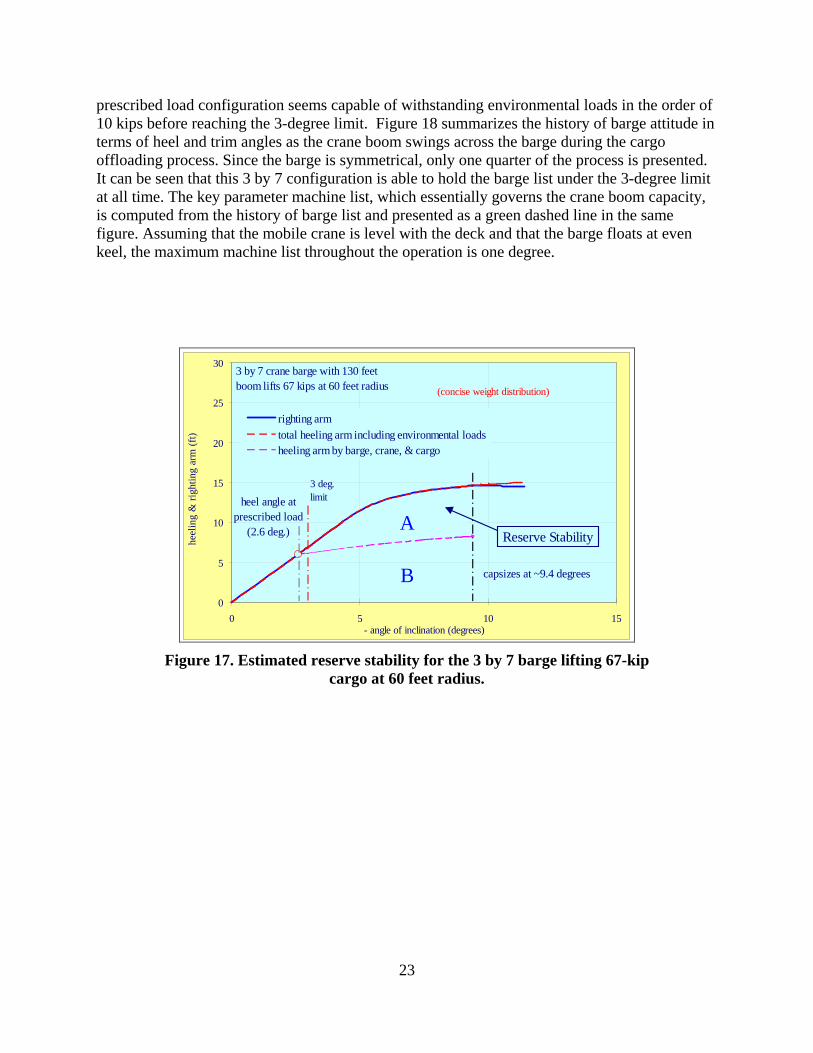
This set of stability curves indicates that 3 by 5 and 3 by 6 ELCAS barges do not possess sufficient hydrostatic stability to hold the resulting barge list under the 3-degree limit required by NAVFAC P-307 guideline for floating derricks. A 3 by 7 ELCAS barge is the minimum size of sufficient potential to support the proposed mobile crane for the intended cargo offloading operations. However, the maximum heel angle indicator does not fully ensure the operational safety as discussed earlier in the paragraph of stability criteria for pontoon barges. The 3 by 7 ELCAS barge is further inspected for its reserve stability available to absorb additional heeling actions due to operational or environmental uncertainties. Findings are presented in Figure 17. This figure indicates that the crane barge will stop at an equilibrium heel angle of 2.6 degrees while lifting a 67-kip cargo at 60 feet radius3. If the lift load cargo continues to increase, the barge is predicted to capsize at about 9.4 degrees. Theoretically, the area under the curve of stability (blue line) beyond the 2.6 degrees is the reserve stability available to absorb additional heeling energy. However, the crane barge and lift load will consume part of the reserve stability shown by Area A under the purple dashed line as the barge rolls further for any reason. Note that this purple line increases with heel angle, reflecting the effect of cargo swing out as the barge rolls further (see Figure 11). Only the Area B enclosed by the blue line (righting arm), the purple dashed line (heeling arm by crane and cargo), and the vertical black dashed chain-dotted line (capsizing angle) is the available reserve for additional heeling energy due to environmental or operational uncertainties. At the moment, there is no documented guideline regulating the required reserve stability for pontoon platform. Such guidelines can only be established with a large empirical database, requiring extensive researches. However, if the general guidelines of the Navy’s wind heel criteria for conventional vessels may be adopted, the 3 by 7 barge at the
3 Note that the additional 16 foot beam width will push the CF moored to the side of the barge further outward by 8 feet.
23
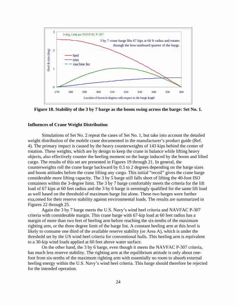
prescribed load configuration seems capable of withstanding environmental loads in the order of 10 kips before reaching the 3-degree limit. Figure 18 summarizes the history of barge attitude in terms of heel and trim angles as the crane boom swings across the barge during the cargo offloading process. Since the barge is symmetrical, only one quarter of the process is presented. It can be seen that this 3 by 7 configuration is able to hold the barge list under the 3-degree limit at all time. The key parameter machine list, which essentially governs the crane boom capacity, is computed from the history of barge list and presented as a green dashed line in the same figure. Assuming that the mobile crane is level with the deck and that the barge floats at even keel, the maximum machine list throughout the operation is one degree.
0
5
10
15
20
25
30
0 5 10 15 - angle of inclination (degrees)
heel
ing
& ri
ghtin
g ar
m (f
t)
righting armtotal heeling arm including environmental loadsheeling arm by barge, crane, & cargo
capsizes at ~9.4 degrees
3 by 7 crane barge with 130 feet boom lifts 67 kips at 60 feet radius
heel angle at prescribed load
(2.6 deg.)
3 deg. limit
(concise weight distribution)
Reserve StabilityA
B
Figure 17. Estimated reserve stability for the 3 by 7 barge lifting 67-kip
cargo at 60 feet radius.
24
0
1
2
3
270 280 290 300 310 320 330 340 350 360
Location of boom in degrees with respect to the barge length
Hee
l & tr
im (d
eg)
heeltrimmachine list
3 by 7 crane barge lifts 67 kips at 60 ft radius and rotatesthrough the bow-starboard quarter of the barge.
3-deg. Limit per NAVFAC P-307
Figure 18. Stability of the 3 by 7 barge as the boom swing across the barge: Set No. 1.
Influences of Crane Weight Distribution
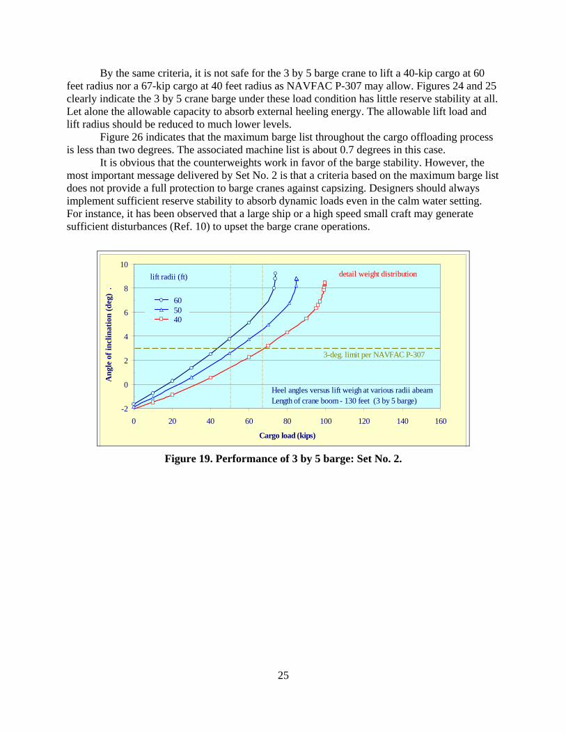
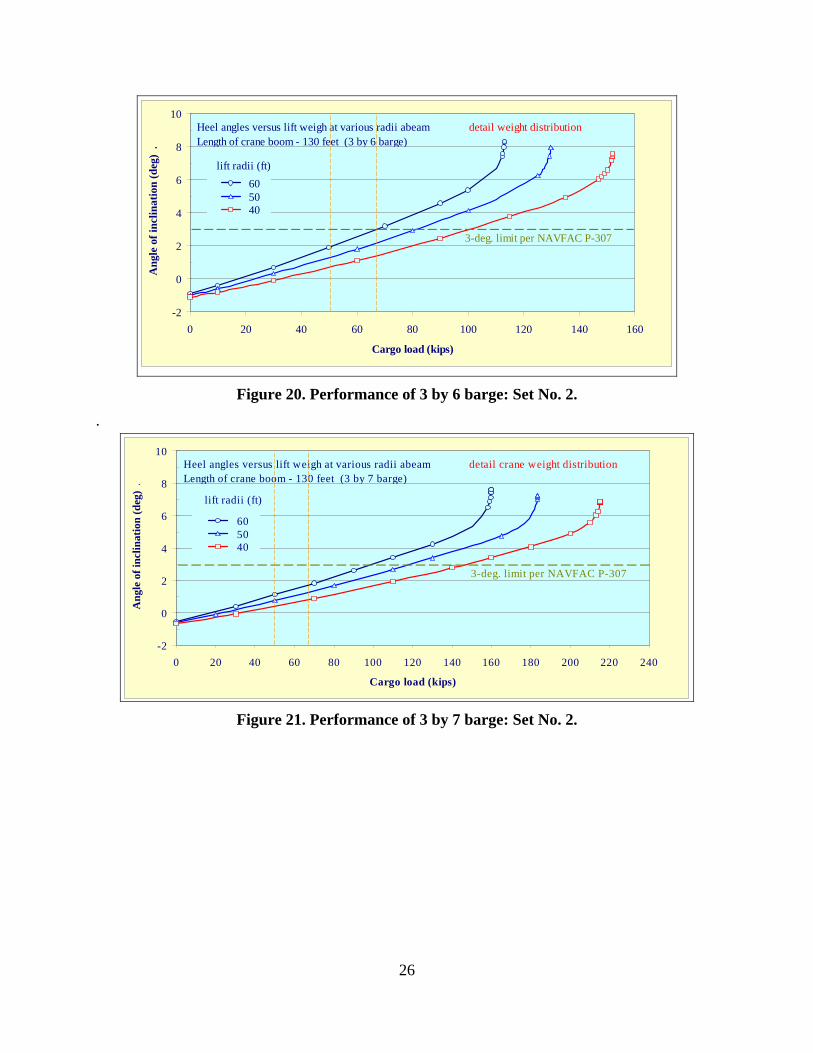
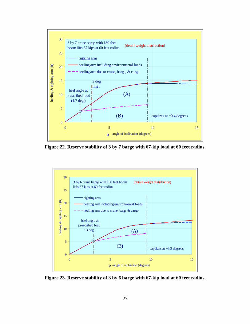
Simulations of Set No. 2 repeat the cases of Set No. 1, but take into account the detailed weight distribution of the mobile crane documented in the manufacturer’s product guide (Ref. 4). The primary impact is caused by the heavy counterweights of 143 kips behind the center of rotation. These weights, which are by design to keep the crane in balance while lifting heavy objects, also effectively counter the heeling moment on the barge induced by the boom and lifted cargo. The results of this set are presented in Figures 19 through 21. In general, the counterweights roll the crane barge backward by 0.5 to 2 degrees depending on the barge sizes and boom attitudes before the crane lifting any cargo. This initial “recoil” gives the crane barge considerable more lifting capacity. The 3 by 5 barge still falls short of lifting the 40-foot ISO containers within the 3-degree limit. The 3 by 7 barge comfortably meets the criteria for the lift load of 67 kips at 60 feet radius and the 3 by 6 barge is seemingly qualified for the same lift load as well based on the threshold of maximum barge list alone. These two barges were further exa,omed for their reserve stability against environmental loads. The results are summarized in Figures 22 through 25.
Again the 3 by 7 barge meets the U.S. Navy’s wind heel criteria and NAVFAC P-307 criteria with considerable margin. This crane barge with 67-kip load at 60 feet radius has a margin of more than two feet of heeling arm before reaching the six-tenths of the maximum righting arm, or the three degree limit of the barge list. A constant heeling arm at this level is likely to consume one third of the available reserve stability (or Area A), which is under the threshold set by the US wind heel criteria for conventional hulls. This heeling arm is equivalent to a 30-kip wind loads applied at 60 feet above water surface.
On the other hand, the 3 by 6 barge, even though it meets the NAVFAC P-307 criteria, has much less reserve stability. The righting arm at the equilibrium attitude is only about one- foot from six-tenths of the maximum righting arm with essentially no room to absorb external heeling energy within the U.S. Navy’s wind heel criteria. This barge should therefore be rejected for the intended operation.
25
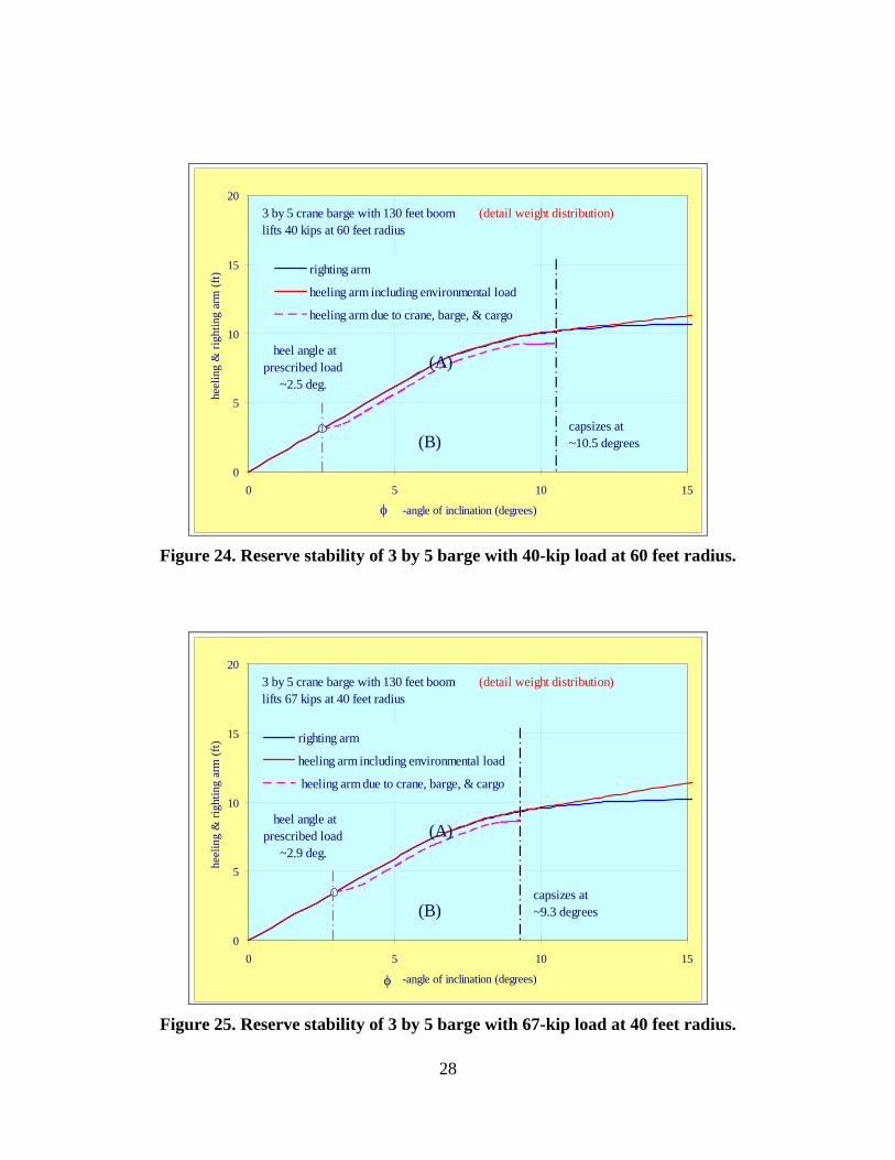
By the same criteria, it is not safe for the 3 by 5 barge crane to lift a 40-kip cargo at 60 feet radius nor a 67-kip cargo at 40 feet radius as NAVFAC P-307 may allow. Figures 24 and 25 clearly indicate the 3 by 5 crane barge under these load condition has little reserve stability at all. Let alone the allowable capacity to absorb external heeling energy. The allowable lift load and lift radius should be reduced to much lower levels.
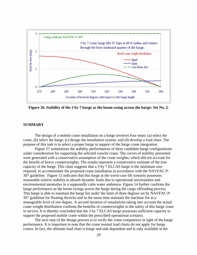
Figure 26 indicates that the maximum barge list throughout the cargo offloading process is less than two degrees. The associated machine list is about 0.7 degrees in this case.
It is obvious that the counterweights work in favor of the barge stability. However, the most important message delivered by Set No. 2 is that a criteria based on the maximum barge list does not provide a full protection to barge cranes against capsizing. Designers should always implement sufficient reserve stability to absorb dynamic loads even in the calm water setting. For instance, it has been observed that a large ship or a high speed small craft may generate sufficient disturbances (Ref. 10) to upset the barge crane operations.
-2
0
2
4
6
8
10
0 20 40 60 80 100 120 140 160
Cargo load (kips)
Ang
le o
f inc
linat
ion
(deg
) .
60 50 40
Heel angles versus lift weigh at various radii abeamLength of crane boom - 130 feet (3 by 5 barge)
3-deg. limit per NAVFAC P-307
lift radii (ft) detail weight distribution
Figure 19. Performance of 3 by 5 barge: Set No. 2.
26
-2
0
2
4
6
8
10
0 20 40 60 80 100 120 140 160
Cargo load (kips)
Ang
le o
f inc
linat
ion
(deg
) .
60 50 40
Heel angles versus lift weigh at various radii abeamLength of crane boom - 130 feet (3 by 6 barge)
3-deg. limit per NAVFAC P-307
lift radii (ft)
detail weight distribution
Figure 20. Performance of 3 by 6 barge: Set No. 2.
.
-2
0
2
4
6
8
10
0 20 40 60 80 100 120 140 160 180 200 220 240
Cargo load (kips)
Ang
le o
f inc
linat
ion
(deg
) .
60 50 40
Heel angles versus lift weigh at various radii abeamLength of crane boom - 130 feet (3 by 7 barge)
3-deg. limit per NAVFAC P-307
lift radii (ft)
detail crane weight distribution
Figure 21. Performance of 3 by 7 barge: Set No. 2.
27
0
5
10
15
20
25
30
0 5 10 15
-angle of inclination (degrees)
heel
ing
& ri
ghtin
g ar
m (f
t)
righting arm
heeling arm including environmental loads
heeling arm due to crane, barge, & cargo
capsizes at ~9.4 degrees
3 by 7 crane barge with 130 feet boom lifts 67 kips at 60 feet radius
(A)
(B)
heel angle at prescribed load
(1.7 deg.)
3 deg. limit
(detail weight distribution)
φ
Figure 22. Reserve stability of 3 by 7 barge with 67-kip load at 60 feet radius.
0
5
10
15
20
25
30
0 5 10 15
-angle of inclination (degrees)
heel
ing
& ri
ghtin
g ar
m (f
t) righting arm
heeling arm including environmental loads
heeling arm due to crane, barg, & cargo
capsizes at ~9.3 degrees
3 by 6 crane barge with 130 feet boom lifts 67 kips at 60 feet radius
(A)
(B)
heel angle at prescribed load
~3 deg.
(detail weight distribution)
φ
Figure 23. Reserve stability of 3 by 6 barge with 67-kip load at 60 feet radius.
28
0
5
10
15
20
0 5 10 15
-angle of inclination (degrees)
heel
ing
& ri
ghtin
g ar
m (f
t) righting arm
heeling arm including environmental load
heeling arm due to crane, barge, & cargo
capsizes at ~10.5 degrees
3 by 5 crane barge with 130 feet boom lifts 40 kips at 60 feet radius
(A)
(B)
heel angle at prescribed load
~2.5 deg.
(detail weight distribution)
φ
Figure 24. Reserve stability of 3 by 5 barge with 40-kip load at 60 feet radius.
0
5
10
15
20
0 5 10 15
-angle of inclination (degrees)
heel
ing
& ri
ghtin
g ar
m (f
t) righting arm
heeling arm including environmental load
heeling arm due to crane, barge, & cargo
capsizes at ~9.3 degrees
3 by 5 crane barge with 130 feet boom lifts 67 kips at 40 feet radius
(A)
(B)
heel angle at prescribed load
~2.9 deg.
(detail weight distribution)
φ
Figure 25. Reserve stability of 3 by 5 barge with 67-kip load at 40 feet radius.
29
0
1
2
3
270 280 290 300 310 320 330 340 350 360
Location of boom in degrees with respect to the barge length
Hee
l & tr
im (d
eg)
heeltrimmachine list
3 by 7 crane barge lifts 67 kips at 60 ft radius and rotates through the bow-starboard quarter of the barge.
detail crane weight distribution
3-deg. Limit per NAVFAC P-307
Figure 26. Stability of the 3 by 7 barge as the boom swing across the barge: Set No. 2.
SUMMARY
The design of a mobile crane installation on a barge involves four steps: (a) select the crane, (b) select the barge, (c) design the installation system, and (d) develop a load chart. The purpose of this task is to select a proper barge in support of the barge crane integration.
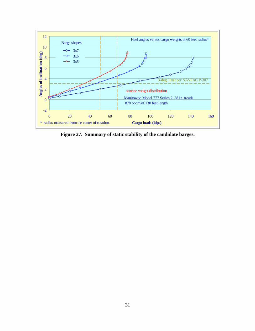
Figure 27 summarizes the stability performances of three candidate barge configurations under consideration for supporting the selected crawler crane. The curves of stability presented were generated with a conservative assumption of the crane weights, which did not account for the benefit of heavy counterweights. The results represent a conservative estimate of the true capacity of the barge. This chart suggests that a 3 by 7 ELCAS barge is the minimum size required to accommodate the proposed crane installation in accordance with the NAVFAC P-307 guideline. Figure 13 indicates that this barge at the worst-case lift scenario possesses reasonable reserve stability to absorb dynamic loads due to operational uncertainties and environmental anomalies in a supposedly calm water ambience. Figure 14 further confirms the barge performance as the boom swings across the barge during the cargo offloading process. This barge is able to maintain the barge list under the limit of three degrees set by NAVFAC P-307 guideline for floating derricks and in the mean time maintain the machine list at a manageable level of one degree. A second iteration of simulations taking into account the actual crane weight distribution confirms the benefits of counterweights to the safety of this barge crane in service. It is thereby concluded that the 3 by 7 ELCAS barge possesses sufficient capacity to support the proposed mobile crane within the prescribed operational scenario.
The next step of the design process is to verify the crane competence in light of the barge performance. It is important to note that the crane normal load charts do not apply for barge cranes. In fact, the ultimate load chart is barge and task dependent and is only available at the
30
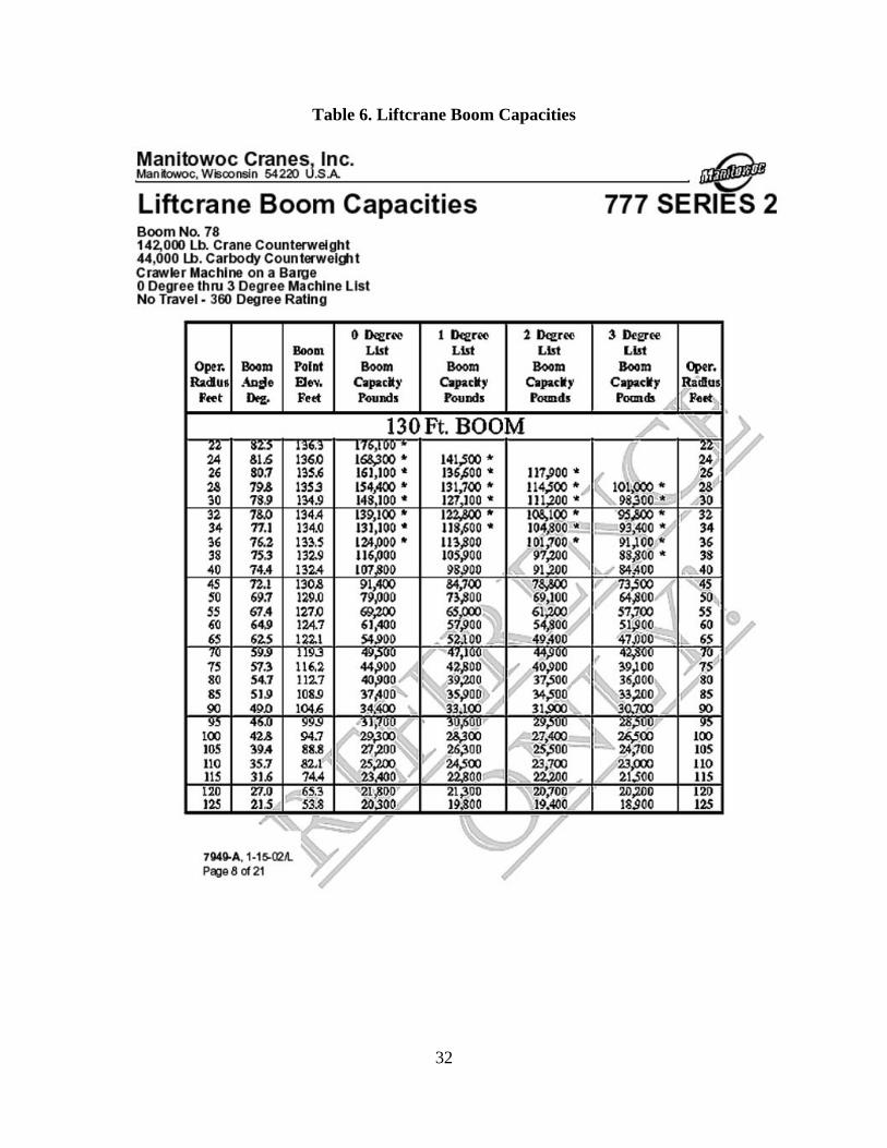
completion of the design process. The present discussion will use a generic load chart for the crawler machine published by the manufacturer for general reference. The load chart pertinent to the prescribed machine is presented in Table 6 as excerpted from Reference 6. Note that the machine list dictates the load capacity of the crane. The machine list, as defined by the manufacturer, is the crane’s out-of-level condition from side-to-side as measured by the angle between horizontal and a line drawn through the centerline of the crane’s boom hinge pins (Figure 6(a)). This is different from the barge list (heel and trim). As the machine rotates on the barge, the barge list will change. Note that the candidate barges are perfectly symmetrical in both principal dimensions and the crane sits at the center of the barge deck. As a result, the barge heels with little trim while the crane extends over the side nearly perpendicular to the barge length. In this condition, the hinge pin remains nearly parallel to the horizon so the machine list is minimal. The same applies when the boom heads in line with the barge length. The worst machine list condition generally occurs when the machine swings over the corners of the barge. The machine lists incurred by this crane installation supported by a 3 by 7 barge in the worst-case cargo offloading scenario were summarized by the green dashed line of Figure 18. It can be seen that the machine list reaches the maximum value of 1.05 degrees when the boom is 45 degrees off the principal axes.
The load chart published by the manufacturer indicates that the proposed crane at a machine list of 1 degree is capable of lifting up to 70 kips at the lift radius of 52 feet. At a list angle of 2 degrees, the maximum allowable load reduces to 66 kips. This qualifies the proposed barge crane for lifting 67-kip containers at the far edge of INLS ferries (52 feet from the barge center) with a narrow margin safety. However, this barge crane falls short of lifting containers at oblique angles to the crane location. The lift radius increases to 74 feet for the crane to reach the far edge of the delivery ferry at 45 degrees off the barge length, as such the lift load shall be confined to 43 kips.
In summary, the installation composed of a crawler crane on the deck of a 3 by 7 ELCAS barge presents high potential of supporting the prescribed cargo transfer mission. This 3 by 7 ELCAS barge is capable of limiting the machine list below the constraints imposed by the manufacturer throughout the cargo offloading cycle. The proposed crane shows sufficient capacity to lift 67-kip containers within the 52-foot operation radius. However, careful planning is required to properly relocate the causeway ferry along the berth and bring the containers on deck within the comfortable lift radius of the proposed barge crane installation before each lift, preferably not exceeding 52 feet from the crane’s center of rotation.
It is important to note that this discussion is based on a generic load chart published by the manufacturer for general reference. The ultimate load capacity of the barge crane can only be determined with a certified load chart pertinent to the prescribed operation scenario. A mobile crane indeed consists of many moving parts. The manufacturer repetitively emphasizes the sensitivity of connecting mechanisms to the machine list. The lifted load capacity is most likely dictated by the machine requirement. It is imperative to include the manufacturer in the process of developing the ultimate load chart.
31
-2
0
2
4
6
8
10
12
0 20 40 60 80 100 120 140 160Cargo loads (kips)
Ang
les o
f inc
linat
ion
(deg
) 3x7 3x6 3x5
Manitowoc Model 777 Series 2 38 in. treads#78 boom of 130 feet length.
3-deg. limit per NAVFAC P-307
Barge shapes
concise weight distribution
Heel angles versus cargo weights at 60 feet radius*
* radius measured from the center of rotation.
Figure 27. Summary of static stability of the candidate barges.
32
Table 6. Liftcrane Boom Capacities
33
CONCLUSIONS
The proposed ELCAS platform of 3 modules long and 5 modules wide is unacceptable due to insufficient stability. The resulting barge crane installation is likely to capsize when attempting to lift a fully laden 40-foot ISO container (67 kips) situated at the far edge of an INLS Causeway Ferry. A wider ELCAS platform of 3 modules long and 7 modules wide is required to support the proposed mobile crane for the intended cargo offloading mission. The resulting barge crane installation holds the barge list under the three degree limit imposed by NAVFAC P-307 guideline for barge crane and provides sufficient reserve stability to absorb operational uncertainties and environmental anomalies in a supposedly calm water ambience. This barge crane installation sustains the maximum machine list to one degree throughout the entire cargo offloading cycle. This qualifies the crane installation to lift 67-kip ISO containers situated at the far edge of an INLS Causeway Ferry at 52 feet lift radius.
High center of gravity is the primary cause for capsizing pontoon-based crane barges. Sheltered waters provide little margin in the scenario of heavy lifting with a long boom. A pontoon barge displays a high initial stiffness. However it capsizes very rapidly once its ultimate capacity is exceeded and leaves no time for remedial actions. Therefore, aggressive lift plans are not recommended.
A criterion based on the maximum heel angle does not provide a full protection to the barge crane against capsizing without the evidence of sufficient reserve dynamic stability to withstand operational uncertainties or environmental loads. REFERENCES 1. NAVFAC Navy Crane Center, “Management of Weight Handling Equipment,” NAVFAC P-
307, June 2003.
2. ANSI/ASME B30.8-2004, “Floating Cranes and Derricks,” American National Standards Institute, 1819 L Street, NW 6th floor Washington, DC 20036 May 01 2004
3. Sarchin, T. H. and L. L. Goldberg, “Stability and Buoyancy Criteria for U. S. Naval Surface Ships,” Transactions SNAME, Vol. 70, 1962
4. Manitowoc Company, Inc., “Model 777 Product Guide,” Manitowoc, Wisconsin, 54220 USA (http://www.kran-modelle.de/Kranmodelle/acrobat/Manitowoc_777.pdf)
5. Manitowoc Company, Inc., “777 Operator’s Manual,” March 27 2008, Control #004-03, Manitowoc, Wisconsin, 54220 USA
6. Manitowoc Company, Inc., “Liftcrane Boom Capacities,” 7949-A, S/N: 7771152, Manitowoc, Wisconsin, 54220 USA Jan 15, 2002
34
7. Goldberg, L. L., “Principle of Naval Architecture, Chapter II: Intact Stability,” The Society of Naval Architects and Marine Engineers, Edited by E. V. Lewis, 1988
8. Huang, T., “A generalized Intact Stability Analysis Procedure for Modular Construction Platforms,” NCEL Technical Note, N-1832, June 1991, Naval Civil Engineering Laboratory, Port Hueneme, CA 93043
9. Huang, E. T., “Stability Assessment of MHP Test Bed for Ocean Tow,” NAVFAC ESC Technical Memorandum, TM-2378-AMP, NAVFAC Engineering Service Center, Port Hueneme, CA 93043, January 24 2005.
10. Huang, E. T., “Passing Ship Effect on Moored Ships at Naval Station Norfolk Waterfront,” NAVFAC ESC Site Specific Report, SSR-3284-AMP, NAVFAC Engineering Service Center, Port Hueneme, CA 93043, July 2008.