single channel loop detector - procon el · single channel loop detector the ld120t is a series of...
TRANSCRIPT
1
Single Channel Loop Detector
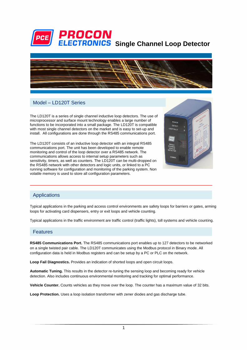
The LD120T is a series of single channel inductive loop detectors. The use of microprocessor and surface mount technology enables a large number of functions to be incorporated into a small package. The LD120T is compatible with most single channel detectors on the market and is easy to set-up and install. All configurations are done through the RS485 communications port.
The LD120T consists of an inductive loop detector with an integral RS485 communications port. The unit has been developed to enable remote monitoring and control of the loop detector over a RS485 network. The communications allows access to internal setup parameters such as sensitivity, timers, as well as counters. The LD120T can be multi-dropped on the RS485 network with other detectors and logic units, or linked to a PC running software for configuration and monitoring of the parking system. Non volatile memory is used to store all configuration parameters.
Typical applications in the parking and access control environments are safety loops for barriers or gates, arming
loops for activating card dispensers, entry or exit loops and vehicle counting.
Typical applications in the traffic environment are traffic control (traffic lights), toll systems and vehicle counting.
RS485 Communications Port. The RS485 communications port enables up to 127 detectors to be networked
on a single twisted pair cable. The LD120T communicates using the Modbus protocol in Binary mode. All
configuration data is held in Modbus registers and can be setup by a PC or PLC on the network.
Loop Fail Diagnostics. Provides an indication of shorted loops and open circuit loops.
Automatic Tuning. This results in the detector re-tuning the sensing loop and becoming ready for vehicle
detection. Also includes continuous environmental monitoring and tracking for optimal performance.
Vehicle Counter. Counts vehicles as they move over the loop. The counter has a maximum value of 32 bits.
Loop Protection. Uses a loop isolation transformer with zener diodes and gas discharge tube.
Features
Applications
Model – LD120T Series
2
Selectable Detect Sensitivity
Selectable UnDetect Sensitivity
Filter Timer & Extend Timer
Selectable Pulse Time
Relay Mode – Pulse on detect, pulse on undetect, presence or Loop fault
Presence Mode –Limited or Unlimited.
Baud Rate
Power Indicator. This LED Indicator illuminates when power is present.
Detect Indicator. This LED Indicator is illuminated when there is a vehicle over the loop or the loop is faulty. This
LED can also be used to determine the loop frequency. On reset, count the number of times the LED flashes.
Multiply this number by 10KHz.For example: if the LED flashes 6 times, then the loop frequency is between
60KHz and 70KHz.
RS485 Communications Indicators. There is a RS485 Rx and Tx LED which illuminate during communications.
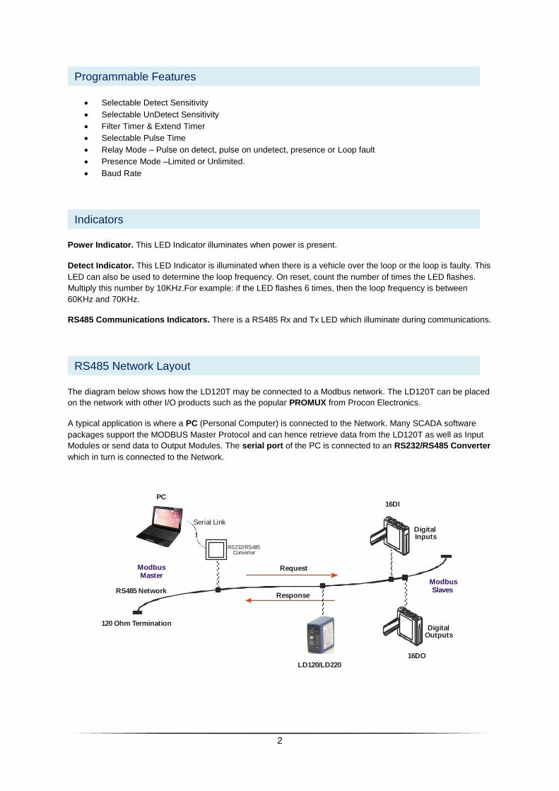
The diagram below shows how the LD120T may be connected to a Modbus network. The LD120T can be placed
on the network with other I/O products such as the popular PROMUX from Procon Electronics.
A typical application is where a PC (Personal Computer) is connected to the Network. Many SCADA software
packages support the MODBUS Master Protocol and can hence retrieve data from the LD120T as well as Input
Modules or send data to Output Modules. The serial port of the PC is connected to an RS232/RS485 Converter
which in turn is connected to the Network.
120 Ohm Termination
ModbusMaster
PC
RS485 Network
DigitalOutputs
16DO
16DI
LD120/LD220
DigitalInputs
ModbusSlaves
Request
Response
RS232/RS485Converter
Serial Link
RS485 Network Layout
Indicators
Programmable Features
3
Power supply LD120T 200 - 260VAC 50Hz 1.5VA
LD121T 100 - 120VAC 60Hz 1.5VA
LD122T 11 - 26VAC/DC 50/60Hz 90mA max.
Presence Relay Mode 0.5A/220VAC (Fail Safe – normally energized)
Pulse Relay Mode 0.5A/220VAC(Non Fail Safe–normally denergised)
Response time Default approximately 120ms after vehicle enters loop. Adjustable 50ms to 10.00 seconds
Indicators LED indicators show: Detect state & Rs485 communications.
Detector tuning range 15 - 1500uH
Loop Frequency Approx. 23 – 130KHz
Environmental tracking Automatic Compensation
Protection Loop isolation transformer with zener diodes and gas discharge tube.
Connector 11 Pin Connector on rear of unit.
Dimensions 80mm (height) X 40mm (width) X 79mm (Depth excl. connector).
Operating Temperature -20°C to +70°C
Storage Temperature -40°C to +85°C
RELAYS
VEHICLE
PRESENT
NO
VEHICLE
LOOP
FAULTY
NO
POWER
PRESENCE
RELAY
N/O CLOSED OPEN CLOSED CLOSED
N/C OPEN CLOSED OPEN OPEN
PULSE
RELAY
N/O PULSE CLOSED OPEN OPEN OPEN
N/C PULSE OPEN CLOSED CLOSED CLOSED
Relay Functionality
Technical Specifications
4
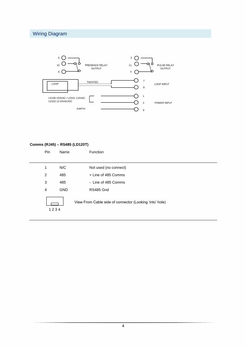
Comms (RJ45) – RS485 (LD120T)
Pin Name Function
1 N/C Not used (no connect)
2 485 + Line of 485 Comms
3 485 - Line of 485 Comms
4 GND RS485 Gnd
View From Cable side of connector (Looking ‘into’ hole)
1 2 3 4
Wiring Diagram
7
LOOP INPUT
8
1
2 POWER INPUT
9
LD100 220VAC / LD101 110VAC
LD102 12-24VAC/DC
EARTH
LOOP TWISTED
CABLE
5 3
10 PRESENCE RELAY 11 PULSE RELAY
OUTPUT OUTPUT
6 4
5
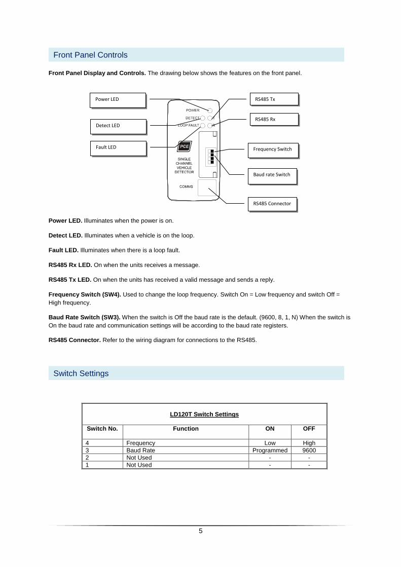
Front Panel Display and Controls. The drawing below shows the features on the front panel.
Power LED. Illuminates when the power is on.
Detect LED. Illuminates when a vehicle is on the loop.
Fault LED. Illuminates when there is a loop fault.
RS485 Rx LED. On when the units receives a message.
RS485 Tx LED. On when the units has received a valid message and sends a reply.
Frequency Switch (SW4). Used to change the loop frequency. Switch On = Low frequency and switch Off =
High frequency.
Baud Rate Switch (SW3). When the switch is Off the baud rate is the default. (9600, 8, 1, N) When the switch is
On the baud rate and communication settings will be according to the baud rate registers.
RS485 Connector. Refer to the wiring diagram for connections to the RS485.
LD120T Switch Settings
Switch No. Function
ON OFF
4 Frequency Low High
3 Baud Rate Programmed 9600
2 Not Used - -
1 Not Used - -
Switch Settings
Front Panel Controls
RS485 Tx
Baud rate Switch
RS485 Connector
Power LED
Frequency Switch
RS485 Rx Detect LED
Fault LED
6
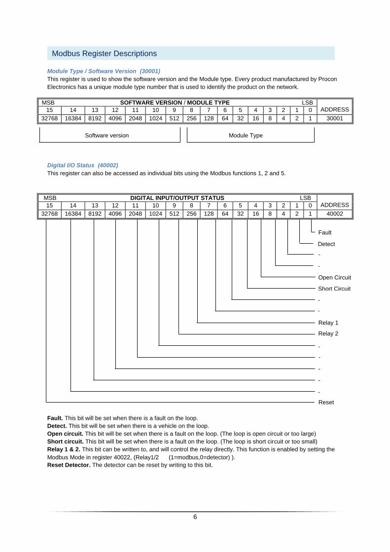
Module Type / Software Version (30001)
This register is used to show the software version and the Module type. Every product manufactured by Procon
Electronics has a unique module type number that is used to identify the product on the network.
MSB SOFTWARE VERSION / MODULE TYPE LSB ADDRESS 15 14 13 12 11 10 9 8 7 6 5 4 3 2 1 0
32768 16384 8192 4096 2048 1024 512 256 128 64 32 16 8 4 2 1 30001
Software version Module Type
Digital I/O Status (40002)
This register can also be accessed as individual bits using the Modbus functions 1, 2 and 5.
MSB DIGITAL INPUT/OUTPUT STATUS LSB ADDRESS 15 14 13 12 11 10 9 8 7 6 5 4 3 2 1 0
32768 16384 8192 4096 2048 1024 512 256 128 64 32 16 8 4 2 1 40002
Fault. This bit will be set when there is a fault on the loop.
Detect. This bit will be set when there is a vehicle on the loop.
Open circuit. This bit will be set when there is a fault on the loop. (The loop is open circuit or too large)
Short circuit. This bit will be set when there is a fault on the loop. (The loop is short circuit or too small)
Relay 1 & 2. This bit can be written to, and will control the relay directly. This function is enabled by setting the
Modbus Mode in register 40022, (Relay1/2 (1=modbus,0=detector) ).
Reset Detector. The detector can be reset by writing to this bit.
Modbus Register Descriptions
Fault
Open Circuit
Short Circuit
-
-
Detect
-
-
Relay 1
Relay 2
-
-
-
-
-
Reset

7
Counter (40003/40004 )
The vehicle counter counts vehicles as they move over the loop. The counter is a 32 bit value which uses two 16
bit Modbus registers.
Loop Frequency (30005/30006)
The loop frequency (Khz) is used to determine how close the loop detector is operating to the upper and lower
limits of the working range (23 – 130 Khz). The loop frequency is also useful to determine how close in frequency
the loop is operating to an adjacent loop to prevent problems with crosstalk. The loop frequency is a 32 bit value
which uses two 16 bit Modbus registers.
Delta (30007)
Change in Loop Inductance. The Delta register displays the inductance change of the loop as the vehicle travels
over the loop. This value is expressed as a percentage change in loop inductance. When no vehicle is present,
the value will toggle about 0%. When a vehicle enters the loop area the value will increase until it reaches a
maximum value determined by the size, shape and height of the vehicle. As the vehicle continues to pass over
the loop the value will fluctuate as the loop senses different parts of the vehicle. When the vehicle leaves the loop
the value will drop back to zero.
When a vehicle enters the loop the value increases. As soon as the value is greater than the sensitivity setting,
the detector presence output will give a detect output. This reading gives a good indication of the performance of
the loop and assists with decision making in setting the sensitivity of the detector.
Delta Min (30008)
Minimum change in inductance from the tuned value. This value is recorded as a vehicle passes over the loop
and is displayed as the vehicle leaves the loop. This value is useful in determining the minimum change in
inductance caused by vehicles over a period of time. This value is updated as each vehicle passes over the loop.
If the change in inductance caused by a vehicle was greater than the previous vehicle, then the reading is not
changed. If the change in inductance is smaller than the previous vehicle, then the reading is updated with the
latest reading. Again this value is useful in determining the optimum sensitivity setting.
Delta Max (30009)
Maximum change in inductance from the tuned value. This value is reset after the vehicle passes the loop. Whilst
over the loop the detector records the peak change in inductance caused by the vehicle.
Node ID (40021)
The node ID is the Modbus address on the network. Every module on the RS485 network must have a unique ID
number. The default ID that the module will always respond to is 254. To use this ID there must only be one
module on the network.
8
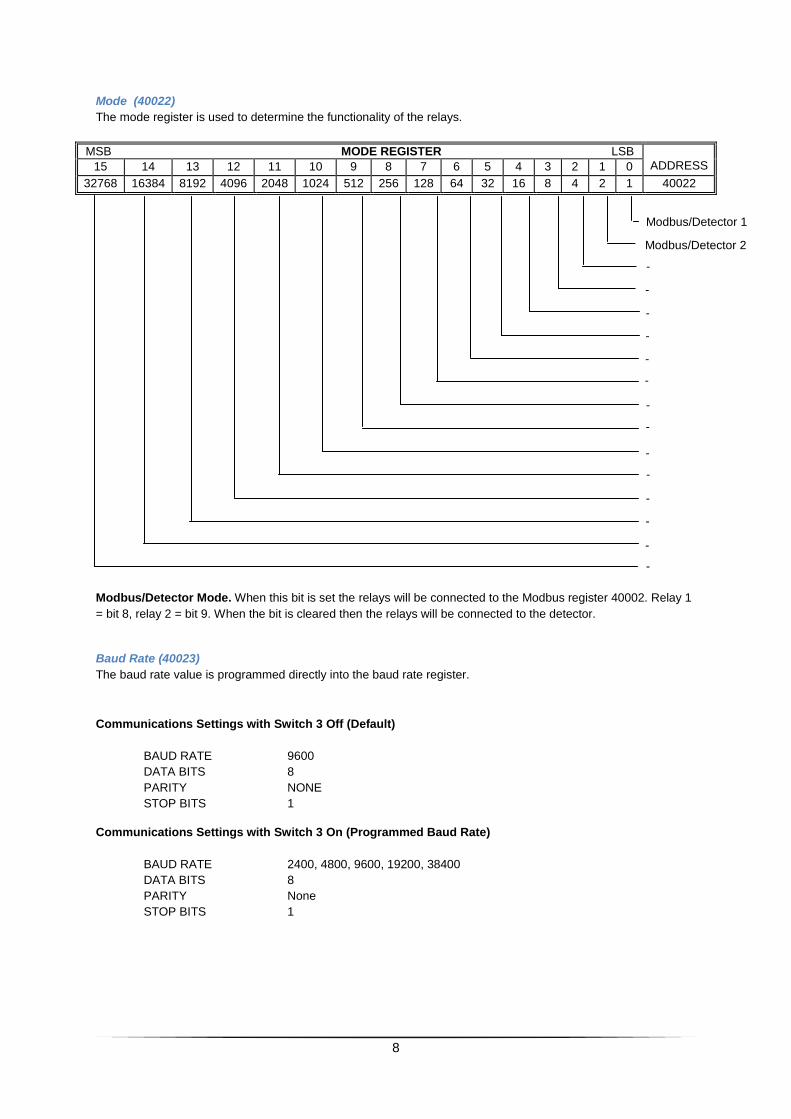
Mode (40022)
The mode register is used to determine the functionality of the relays.
MSB MODE REGISTER LSB ADDRESS 15 14 13 12 11 10 9 8 7 6 5 4 3 2 1 0
32768 16384 8192 4096 2048 1024 512 256 128 64 32 16 8 4 2 1 40022
Modbus/Detector Mode. When this bit is set the relays will be connected to the Modbus register 40002. Relay 1
= bit 8, relay 2 = bit 9. When the bit is cleared then the relays will be connected to the detector.
Baud Rate (40023)
The baud rate value is programmed directly into the baud rate register.
Communications Settings with Switch 3 Off (Default)
BAUD RATE 9600
DATA BITS 8
PARITY NONE
STOP BITS 1
Communications Settings with Switch 3 On (Programmed Baud Rate)
BAUD RATE 2400, 4800, 9600, 19200, 38400
DATA BITS 8
PARITY None
STOP BITS 1
Modbus/Detector 1
-
-
-
-
Modbus/Detector 2
-
-
-
-
-
-
-
-
-
-
9
Detector Sensitivity (40025)
The detect sensitivity is the minimum change in inductance required to produce a detect output when the vehicle
enters the loop. (%ΔL/L). (Value x 0.01%)
Detector Undetect Sensitivity (40026)
This is the level that the detector will use to go out of detect when the vehicle leaves the loop. (Value x 0.01%)
Filter (40027)
This timer is used to provide a delay between detection of the vehicle and switching of the output relay. This
delay is normally used to prevent false detection of small or fast moving objects. (Value x 5ms)
Extend – Undetect Time (40028)
This feature extends the presence output relay after the vehicle has left the loop. (Value x 5ms)
Pulse Time (40029)
This feature sets the length of time that the pulse relay will be energized. (Value x 5ms)
Presence Mode (40030)
The presence time can be configured for an unlimited time depending on the value of the %ΔL/L, or a limited
time. The limited time presence is normally used in traffic applications. 0 = Unlimited Presence, 1 = Permanent
Presence, 2 = 1 Hour, 3 = 10 Minutes, 4 = 3 Minutes, 5 = 1 Second presence (Passage mode).
Relay 2 Mode (40031)
The mode of Relay 2 is configured by entering the value as follows: 0 = Pulse on detect, 1 = Pulse on Undetect,
2 = Presence, 3 = Loop Fault Relay.
10
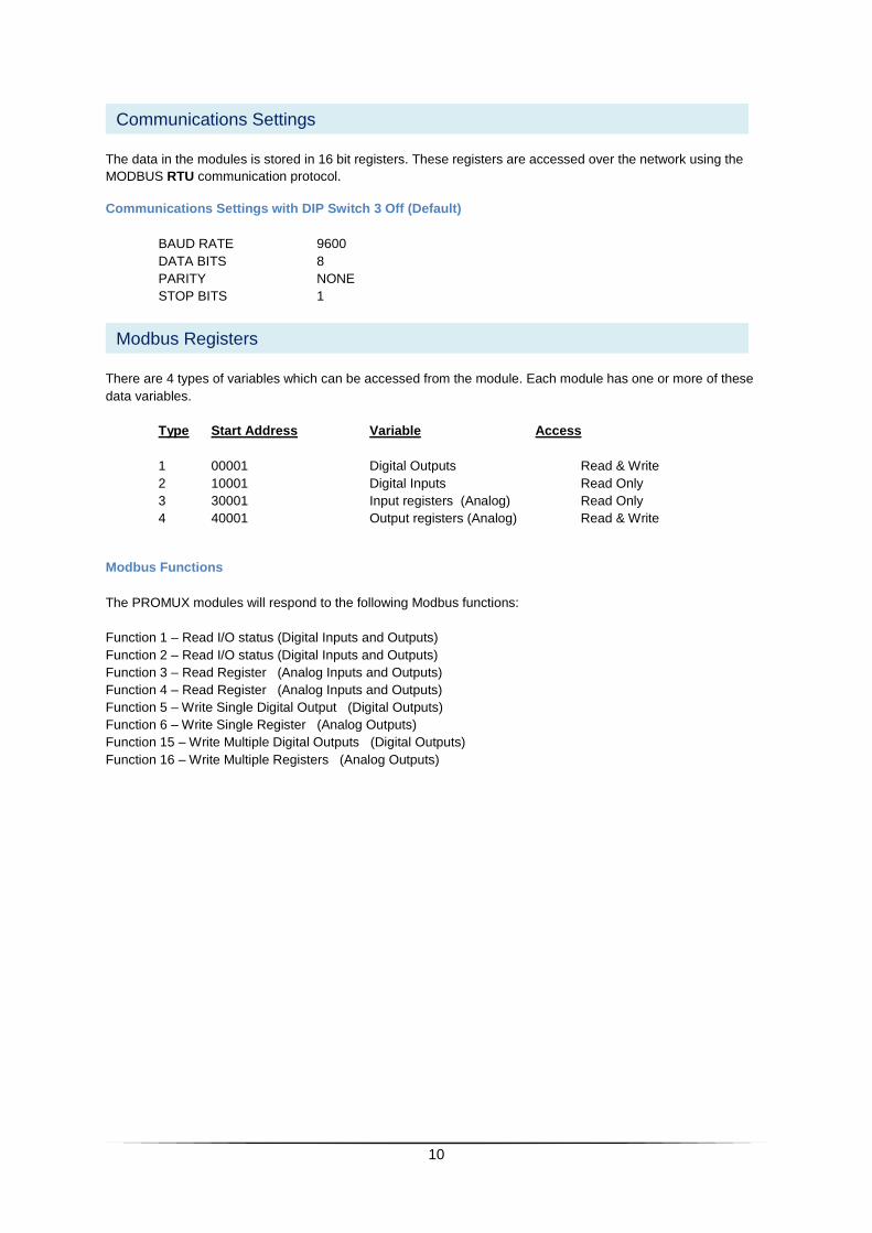
The data in the modules is stored in 16 bit registers. These registers are accessed over the network using the
MODBUS RTU communication protocol.
Communications Settings with DIP Switch 3 Off (Default)
BAUD RATE 9600
DATA BITS 8
PARITY NONE
STOP BITS 1
There are 4 types of variables which can be accessed from the module. Each module has one or more of these
data variables.
Type Start Address Variable Access
1 00001 Digital Outputs Read & Write
2 10001 Digital Inputs Read Only
3 30001 Input registers (Analog) Read Only
4 40001 Output registers (Analog) Read & Write
Modbus Functions
The PROMUX modules will respond to the following Modbus functions:
Function 1 – Read I/O status (Digital Inputs and Outputs)
Function 2 – Read I/O status (Digital Inputs and Outputs)
Function 3 – Read Register (Analog Inputs and Outputs)
Function 4 – Read Register (Analog Inputs and Outputs)
Function 5 – Write Single Digital Output (Digital Outputs)
Function 6 – Write Single Register (Analog Outputs)
Function 15 – Write Multiple Digital Outputs (Digital Outputs)
Function 16 – Write Multiple Registers (Analog Outputs)
Modbus Registers
Communications Settings
11
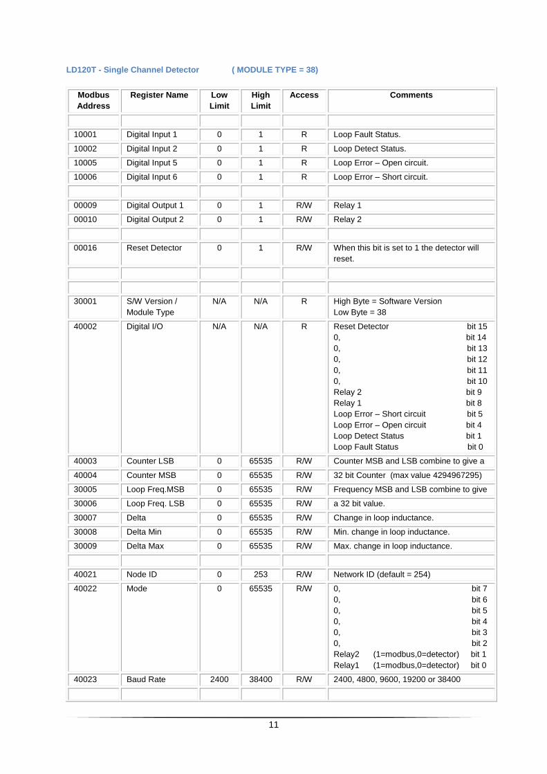
LD120T - Single Channel Detector ( MODULE TYPE = 38)
Modbus
Address
Register Name Low
Limit
High
Limit
Access Comments
10001 Digital Input 1 0 1 R Loop Fault Status.
10002 Digital Input 2 0 1 R Loop Detect Status.
10005 Digital Input 5 0 1 R Loop Error – Open circuit.
10006 Digital Input 6 0 1 R Loop Error – Short circuit.
00009 Digital Output 1 0 1 R/W Relay 1
00010 Digital Output 2 0 1 R/W Relay 2
00016 Reset Detector 0 1 R/W When this bit is set to 1 the detector will
reset.
30001 S/W Version /
Module Type
N/A N/A R High Byte = Software Version
Low Byte = 38
40002 Digital I/O N/A N/A R Reset Detector bit 15
0, bit 14
0, bit 13
0, bit 12
0, bit 11
0, bit 10
Relay 2 bit 9
Relay 1 bit 8
Loop Error – Short circuit bit 5
Loop Error – Open circuit bit 4
Loop Detect Status bit 1
Loop Fault Status bit 0
40003 Counter LSB 0 65535 R/W Counter MSB and LSB combine to give a
40004 Counter MSB 0 65535 R/W 32 bit Counter (max value 4294967295)
30005 Loop Freq.MSB 0 65535 R/W Frequency MSB and LSB combine to give
30006 Loop Freq. LSB 0 65535 R/W a 32 bit value.
30007 Delta 0 65535 R/W Change in loop inductance.
30008 Delta Min 0 65535 R/W Min. change in loop inductance.
30009 Delta Max 0 65535 R/W Max. change in loop inductance.
40021 Node ID 0 253 R/W Network ID (default = 254)
40022 Mode 0 65535 R/W 0, bit 7
0, bit 6
0, bit 5
0, bit 4
0, bit 3
0, bit 2
Relay2 (1=modbus,0=detector) bit 1
Relay1 (1=modbus,0=detector) bit 0
40023 Baud Rate 2400 38400 R/W 2400, 4800, 9600, 19200 or 38400
12
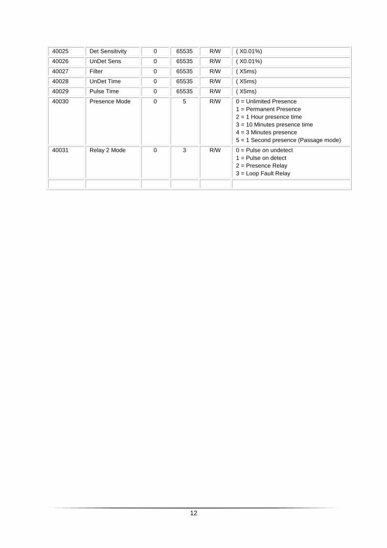
40025 Det Sensitivity 0 65535 R/W ( X0.01%)
40026 UnDet Sens 0 65535 R/W ( X0.01%)
40027 Filter 0 65535 R/W ( X5ms)
40028 UnDet Time 0 65535 R/W ( X5ms)
40029 Pulse Time 0 65535 R/W ( X5ms)
40030 Presence Mode 0 5 R/W 0 = Unlimited Presence
1 = Permanent Presence
2 = 1 Hour presence time
3 = 10 Minutes presence time
4 = 3 Minutes presence
5 = 1 Second presence (Passage mode)
40031 Relay 2 Mode 0 3 R/W 0 = Pulse on undetect
1 = Pulse on detect
2 = Presence Relay
3 = Loop Fault Relay
13
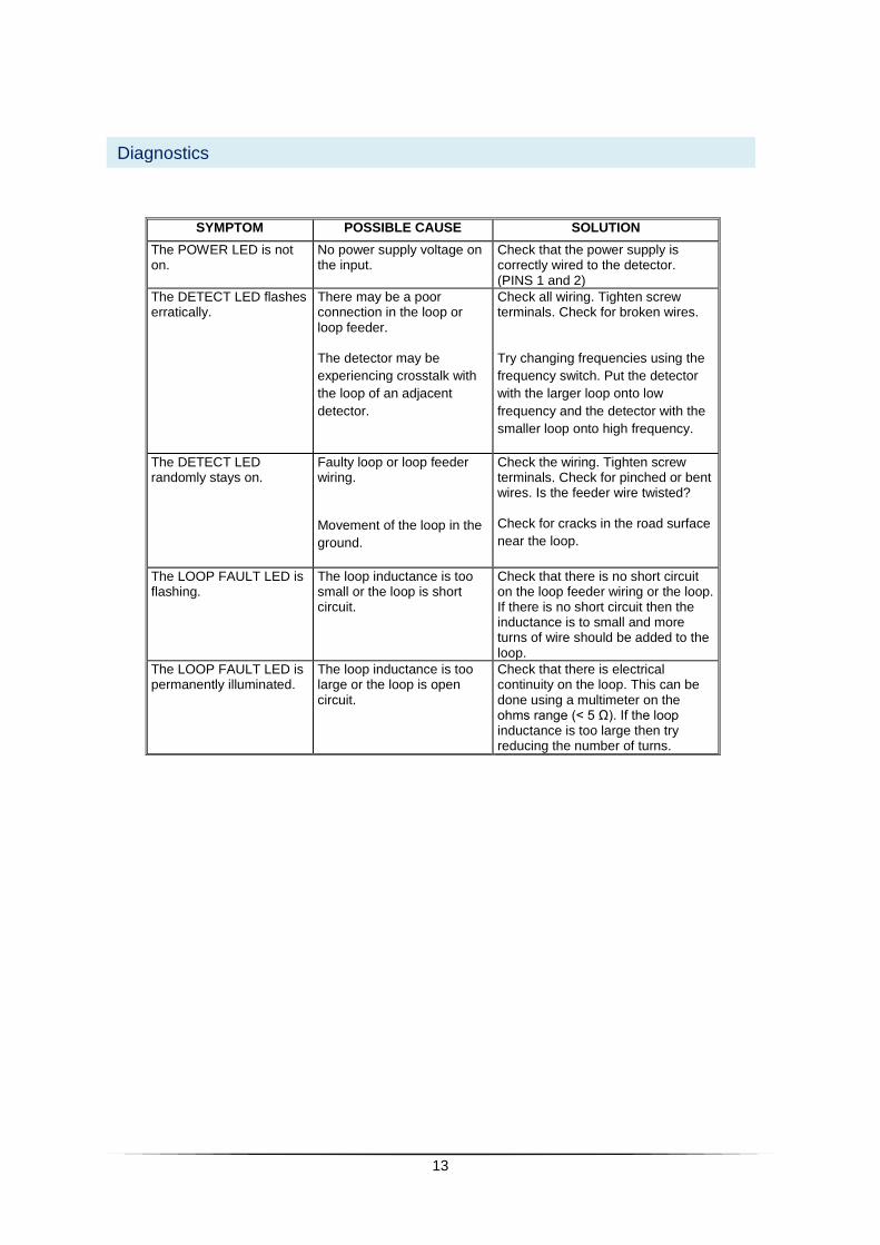
SYMPTOM POSSIBLE CAUSE SOLUTION
The POWER LED is not on.
No power supply voltage on the input.
Check that the power supply is correctly wired to the detector. (PINS 1 and 2)
The DETECT LED flashes erratically.
There may be a poor connection in the loop or loop feeder.
The detector may be
experiencing crosstalk with
the loop of an adjacent
detector.
Check all wiring. Tighten screw terminals. Check for broken wires.
Try changing frequencies using the
frequency switch. Put the detector
with the larger loop onto low
frequency and the detector with the
smaller loop onto high frequency.
The DETECT LED randomly stays on.
Faulty loop or loop feeder wiring.
Movement of the loop in the
ground.
Check the wiring. Tighten screw terminals. Check for pinched or bent wires. Is the feeder wire twisted?
Check for cracks in the road surface
near the loop.
The LOOP FAULT LED is flashing.
The loop inductance is too small or the loop is short circuit.
Check that there is no short circuit on the loop feeder wiring or the loop. If there is no short circuit then the inductance is to small and more turns of wire should be added to the loop.
The LOOP FAULT LED is permanently illuminated.
The loop inductance is too large or the loop is open circuit.
Check that there is electrical continuity on the loop. This can be done using a multimeter on the ohms range (< 5 Ω). If the loop inductance is too large then try reducing the number of turns.
Diagnostics
14
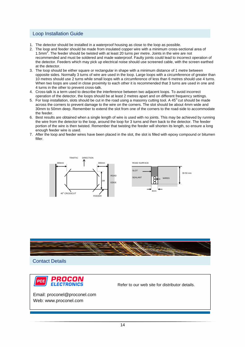
1. The detector should be installed in a waterproof housing as close to the loop as possible. 2. The loop and feeder should be made from insulated copper wire with a minimum cross-sectional area of
1.5mm2. The feeder should be twisted with at least 20 turns per metre. Joints in the wire are not
recommended and must be soldered and made waterproof. Faulty joints could lead to incorrect operation of the detector. Feeders which may pick up electrical noise should use screened cable, with the screen earthed at the detector.
3. The loop should be either square or rectangular in shape with a minimum distance of 1 metre between opposite sides. Normally 3 turns of wire are used in the loop. Large loops with a circumference of greater than 10 metres should use 2 turns while small loops with a circumference of less than 6 metres should use 4 turns. When two loops are used in close proximity to each other it is recommended that 3 turns are used in one and 4 turns in the other to prevent cross-talk.
4. Cross-talk is a term used to describe the interference between two adjacent loops. To avoid incorrect operation of the detector, the loops should be at least 2 metres apart and on different frequency settings.
5. For loop installation, slots should be cut in the road using a masonry cutting tool. A 45o cut should be made
across the corners to prevent damage to the wire on the corners. The slot should be about 4mm wide and 30mm to 50mm deep. Remember to extend the slot from one of the corners to the road-side to accommodate the feeder.
6. Best results are obtained when a single length of wire is used with no joints. This may be achieved by running the wire from the detector to the loop, around the loop for 3 turns and then back to the detector. The feeder portion of the wire is then twisted. Remember that twisting the feeder will shorten its length, so ensure a long enough feeder wire is used.
7. After the loop and feeder wires have been placed in the slot, the slot is filled with epoxy compound or bitumen filler.
Contact Details
Loop Installation Guide
Refer to our web site for distributor details.
Email: [email protected]
Web: www.proconel.com
300mm 300mm
1M
ROAD
EDGE
45O CROSSCUT
FEEDER
TRAFFIC DIRECTION
4mm
ROAD SURFACE
30-50 mm
SLOT
SEALANT WIRES