shadow v - wintriss.com · shadow safety light curtains ! danger ... turn off and disconnect power...
TRANSCRIPT
Shadow V®
Safety Light Curtain1087300Rev. F April 2010
Tech Support Hotline 800-586-8324 8-5 EST
www.wintriss.com
Wintriss Controls Group, LLC100 Discovery WayUnit 110Acton MA 01720 USAPhone (800) 586-8324Fax (978) 263-2048
PRINTED IN USA DA45889
®
®
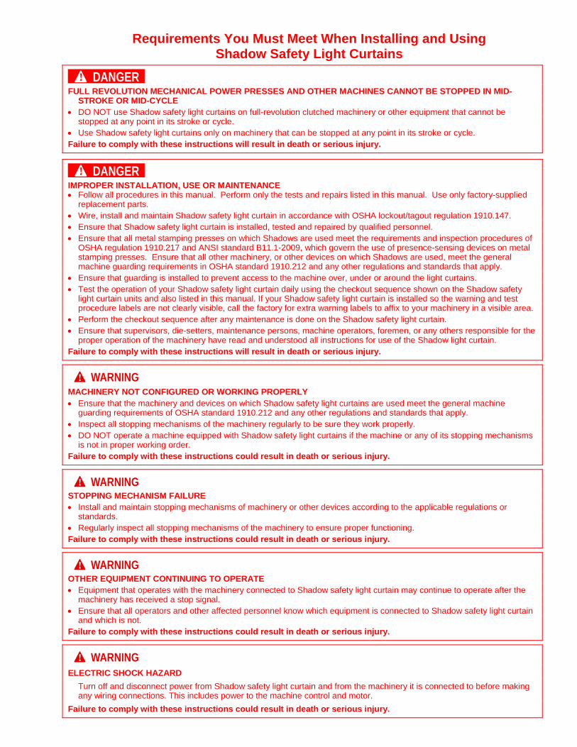
Requirements You Must Meet When Installing and Using Shadow Safety Light Curtains
DANGER! FULL REVOLUTION MECHANICAL POWER PRESSES AND OTHER MACHINES CANNOT BE STOPPED IN MID-
STROKE OR MID-CYCLE DO NOT use Shadow safety light curtains on full-revolution clutched machinery or other equipment that cannot be
stopped at any point in its stroke or cycle. Use Shadow safety light curtains only on machinery that can be stopped at any point in its stroke or cycle. Failure to comply with these instructions will result in death or serious injury.
DANGER! IMPROPER INSTALLATION, USE OR MAINTENANCE Follow all procedures in this manual. Perform only the tests and repairs listed in this manual. Use only factory-supplied
replacement parts. Wire, install and maintain Shadow safety light curtain in accordance with OSHA lockout/tagout regulation 1910.147. Ensure that Shadow safety light curtain is installed, tested and repaired by qualified personnel. Ensure that all metal stamping presses on which Shadows are used meet the requirements and inspection procedures of
OSHA regulation 1910.217 and ANSI standard B11.1-2009, which govern the use of presence-sensing devices on metal stamping presses. Ensure that all other machinery, or other devices on which Shadows are used, meet the general machine guarding requirements in OSHA standard 1910.212 and any other regulations and standards that apply.
Ensure that guarding is installed to prevent access to the machine over, under or around the light curtains. Test the operation of your Shadow safety light curtain daily using the checkout sequence shown on the Shadow safety
light curtain units and also listed in this manual. If your Shadow safety light curtain is installed so the warning and test procedure labels are not clearly visible, call the factory for extra warning labels to affix to your machinery in a visible area.
Perform the checkout sequence after any maintenance is done on the Shadow safety light curtain. Ensure that supervisors, die-setters, maintenance persons, machine operators, foremen, or any others responsible for the
proper operation of the machinery have read and understood all instructions for use of the Shadow light curtain. Failure to comply with these instructions will result in death or serious injury.
WARNING! MACHINERY NOT CONFIGURED OR WORKING PROPERLY Ensure that the machinery and devices on which Shadow safety light curtains are used meet the general machine
guarding requirements of OSHA standard 1910.212 and any other regulations and standards that apply. Inspect all stopping mechanisms of the machinery regularly to be sure they work properly. DO NOT operate a machine equipped with Shadow safety light curtains if the machine or any of its stopping mechanisms
is not in proper working order. Failure to comply with these instructions could result in death or serious injury.
WARNING! STOPPING MECHANISM FAILURE Install and maintain stopping mechanisms of machinery or other devices according to the applicable regulations or
standards. Regularly inspect all stopping mechanisms of the machinery to ensure proper functioning. Failure to comply with these instructions could result in death or serious injury.
WARNING! OTHER EQUIPMENT CONTINUING TO OPERATE Equipment that operates with the machinery connected to Shadow safety light curtain may continue to operate after the
machinery has received a stop signal. Ensure that all operators and other affected personnel know which equipment is connected to Shadow safety light curtain
and which is not. Failure to comply with these instructions could result in death or serious injury.
WARNING! ELECTRIC SHOCK HAZARD
Turn off and disconnect power from Shadow safety light curtain and from the machinery it is connected to before making any wiring connections. This includes power to the machine control and motor.
Failure to comply with these instructions could result in death or serious injury.
Changes for Revision F of the
Shadow V User Manual (1087300)
This revision of the Shadow V Safety Light Curtain User Manual covers all Shadow V models.
The changes include:
Updates to the ANSI standards provided in Appendix A, ANSI B11.1-2009 replacing B11.1-2001, B11.19-2003 replacing B11.19-1990

Thank you for purchasing a Wintriss Product. We appreciate your business and want to do whatever we can to ensure your satisfaction. Wintriss products are built to stay on the job day after day, and are backed by an ironclad guarantee, international standards approvals, and unbeatable support. Whenever you need assistance or service, we back all our products with excellent spare parts inventories, training programs, and prompt repair service. We would like to share with you a list of service options–probably the largest number of service options offered in the industry.
• Technical Assistance
We offer a toll-free line for technical assistance. Call our Wintriss Technical Support Hotline at 1-800-586-TECH (8324) should you have any questions about your equipment. Our technical staff is ready to assist you Monday through Friday, 8 a.m. to 5 p.m. EST. In many cases our experienced technical staff can resolve your inquiry right over the phone.
• Return Authorization
Please call our “800” number for a return authorization (RMA) number to return a product for repair. Returned goods must arrive freight prepaid. In order to process your return quickly, we ask that you provide us with the following pertinent information when you call: purchase order number, shipping address, contact name and telephone number, and product type. The assigned RMA number should appear on all packages returned to Wintriss Controls Group to ensure prompt service.
At the time of requesting an RMA, you will be quoted a flat-rate repair price for the product you are returning. We ask that you either fax us a PO for that amount or enclose the PO with the returned item. This will enable us to ship the item back to you as soon as the repair has been completed. If the item cannot be repaired or there are additional charges, you will be contacted for approval.
Please be sure to carefully pack all returned items and ship to our Acton, MA location.
• Expedited Repair Program
Rush service providing 48 hour turnaround is available for most products upon request. An Expedite Fee will be applied to our standard repair rate.
• Board Exchange Program
If your needs are urgent, you can take advantage of out Board Exchange (EX) program. Call our “800” number between 8 a.m. to 5 p.m. EST and we will send a replacement to you overnight. A fee does apply to this service. Contact Wintriss Technical Support at 800-586-8324 for details.
• Service Center
Our Service Center for product service is located at our headquarters in Acton, MA. If your equipment requires repair, please contact us at 800-586-8324 to obtain a return authorization number.
Nationwide field service is also available. Contact the Wintriss Technical Support group at 800-586-8324.
• Product Training
We also offer both product training and maintenance/troubleshooting courses at our Acton, MA and Chicago-area facilities. On-site training is available from the factory or through your local Wintriss representative.
• Restocking Charge
Returned goods are subject to a 20% restocking charge if returned for credit. The minimum charge is $50, not to exceed $250 per item.
Whatever the product, we are committed to satisfying you with innovative engineering, quality construction, reliable performance, and ongoing, helpful support. Call us whenever you need assistance.
Shadow V Safety Light Curtain User Manual 1087300 Table of Contents page i
Table of Contents
Chapter 1 – Shadow ®
V Safety Light Curtain...................................................1
Safety Compliance......................................................................................................................................2 Shadows Provide Excellent Protection .......................................................................................................2 How Shadow Works...................................................................................................................................3
Electricity to Light to Electricity............................................................................................................3 Sequenced Light Pulses .........................................................................................................................4 Stop Signal Sent to Shadow Control Relays ..........................................................................................5
Shadow and Control Reliability..................................................................................................................5 Indicator Lights on Shadows ......................................................................................................................6
Receiver indicators.................................................................................................................................6 Transmitter indicator..............................................................................................................................6
Object Sensitivity .......................................................................................................................................7 Size and Scanning Distance........................................................................................................................7 Shadow Is Easy to Maintain .......................................................................................................................7 Weld Shields for Extra Protection ..............................................................................................................7
Chapter 2 – Installation and Checkout............................................................11
Installation Overview ...............................................................................................................................12 Overview of Steps Necessary to Install Shadow..................................................................................12 Correct Light Curtain and Safeguarding Installation ...........................................................................12
Installation Procedure ...............................................................................................................................14 Calculating the Safety Distance ...........................................................................................................15 Height Considerations..........................................................................................................................23 Designing and Mounting Brackets.......................................................................................................23 Wiring and Loosely Mounting Your Shadow Light Curtains ..............................................................35 Remote Testing of PLC Input Modules ...............................................................................................47 Aligning and Tightening Down Your Shadow Light Curtains.............................................................48 Diagnostic Steps to Perform Before Shadow Operation ......................................................................50
Final Checkout Sequence .........................................................................................................................52
Chapter 3 – Floating and Blanking Windows .................................................55
Blanking Windows ...................................................................................................................................56 Blanking Windows Affect Safety Distance .........................................................................................56 Adding to Safety Distance for Fixed Blanking ....................................................................................57 Installing Master Blanking Window ....................................................................................................58
Floating Window ......................................................................................................................................61 Adding to Safety Distance for Floating Window.................................................................................62 How to Enable the Floating Window Feature ......................................................................................62
Chapter 4 – Troubleshooting ...........................................................................63
Checks and Repairs You Can Make .........................................................................................................63 Checking and Cleaning Windows ............................................................................................................65
1087300 Shadow V Safety Light Curtain User Manual
Page ii Table of Contents
Checking and Correcting Shadow Alignment ..........................................................................................65 Alignment problem or bad phototransistor...........................................................................................65
Checking and Correcting Crosstalk ..........................................................................................................66 Checking and Replacing Fuses .................................................................................................................66 Checking and Replacing Indicator Lamps................................................................................................68 Checking and Replacing Control Relays ..................................................................................................69
If Relay Has Failed Completely ...........................................................................................................70
Appendix A – Extracts from OSHA Regulations and ANSI Standards .........73
Section 1— OSHA regulation 1910.217 ..................................................................................................73 Section 2— Extracts from ANSI Standards for Presence-sensing Devices ..............................................77
Appendix B – Daily Tests .................................................................................93
Daily Tests in English...............................................................................................................................93 Tests Quotidiens du Rideau de Lumiere ...................................................................................................94 Daily Tests in French................................................................................................................................94
Index...................................................................................................................95
Wintriss Manuals...............................................................................................97
List of Figures Figure 1-1. Shadow Light Curtain .........................................................................................................................4 Figure 1-2. Weld Shield on a “Weld Shield Ready” Shadow................................................................................8 Figure 2-1. Prevent Reaching Over, Under or Around a Light Curtain...............................................................13 Figure 2-2. Closing Gaps with Supplementary Mechanical Guards....................................................................13 Figure 2-3. Measuring Distance Between Pinch Point ........................................................................................16 Figure 2-4. Plan View Illustrating “Pass-through Protection”.............................................................................22 Figure 2-5. Brackets for Shadow .........................................................................................................................25 Figure 2-6. Shadow Mounting Dimensions.........................................................................................................26 Figure 2-7. Transmitter and Receiver Properly Aligned......................................................................................28 Figure 2-8. Wrong — Transmitter and Receiver NOT Aligned ..........................................................................28 Figure 2-9. Simplified View of How Shadow Light Curtains Align ...................................................................29 Figure 2-10. Aligning Brackets Using Mounting Holes ......................................................................................30 Figure 2-11. Shadow Mirror Dimensions ............................................................................................................32 Figure 2-12. Using Shadow Light Curtains with Mirrors, Example....................................................................33 Figure 2-13. One Way to Avoid Crosstalk - Reversing Transmitters (TX) and Receivers (RX) ........................34 Figure 2-14. Removing Screws from Shadow Cover ..........................................................................................36 Figure 2-15. Wiring Connector Location on Shadow Transmitter ......................................................................37 Figure 2-16. Wiring Connector for Shadow Transmitter.....................................................................................38 Figure 2-17. Inserting Wires................................................................................................................................38 Figure 2-18. Schematic Showing Shadow Relays Wired to Emergency Stop Circuit.........................................40 Figure 2-19. Wiring Connector for Shadow Receiver .........................................................................................41 Figure 2-20. Connecting Shadow V to WPC II Wintriss Clutch/Brake Control .................................................43 Figure 2-21. Connecting Shadow V to WPC 1000 Clutch/Brake Control...........................................................44 Figure 2-22. Connecting Shadow V to WPC I Wintriss Press Control ..............................................................45 Figure 3-1. Connecting Master Blanking Window..............................................................................................59 Figure 3-2. Coil Stock Unwinding Using Floating Window ...............................................................................61 Figure 4-1. Location of Fuse and Indicator Lamp on Shadow Transmitter .........................................................67 Figure 4-2. Location of Fuses, Indicator Lamps and Relays on Receiver ...........................................................68
Shadow V Safety Light Curtain User Manual 1087300
Table of Contents Page iii
How to Use the Manual This is the installation and reference manual for the Shadow Safety Light Curtain. It has information about how to install Shadow, as well as pertinent information about OSHA and ANSI requirements.
Chapter 1, Shadow Safety Light Curtain, introduces you to Shadow, tells how it works — specifically about control reliability, and explains how to use this product.
Chapter 2, Installation and Checkout, gives the instructions for installing Shadow. This chapter also includes installation of the mirrors, as well as installation information when installing for different applications. At the end of the chapter is a diagnostic and checkout section. Be sure to check out your Shadows prior to operating the machinery.
Chapter 3, Floating and Blanking Windows, tells what you need to know about using blanking and floating windows, including installation and safety distance.
Chapter 4, Troubleshooting, provides information to help diagnose and correct problems you may encounter when using a Shadow Light Curtain.
Appendix A, OSHA Regulations and ANSI Standards, gives excerpts from documents related presence-sensing safety devices.
Appendix B, Daily Tests, contains instructions for the daily tests in English and French.
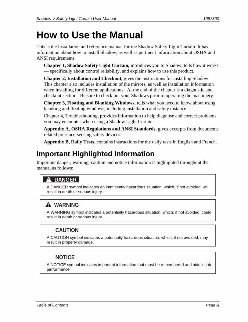
Important Highlighted Information Important danger, warning, caution and notice information is highlighted throughout the manual as follows:
DANGER! A DANGER symbol indicates an imminently hazardous situation, which, if not avoided, will
result in death or serious injury.
WARNING! A WARNING symbol indicates a potentially hazardous situation, which, if not avoided, could
result in death or serious injury.
CAUTION A CAUTION symbol indicates a potentially hazardous situation, which, if not avoided, may
result in property damage.
NOTICE A NOTICE symbol indicates important information that must be remembered and aids in job
performance.

1087300 Shadow V Safety Light Curtain User Manual
Page iv Table of Contents
Warranty
Wintriss Controls warrants that Wintriss electronic controls are free from defects in material and workmanship under normal use and service for a period of one year (two years for Shadow light curtains) from date of shipment. All software products (LETS and SBR), electro-mechanical assemblies, and sensors are warranted to be free from defects in material and workmanship under normal use and service for a period of 90 days from date of shipment. Wintriss’s obligations under this warranty are limited to repairing or replacing, at its discretion and at its factory or facility, any products which shall, within the applicable period after shipment, be returned to Wintriss Controls freight prepaid, and which are, after examination, disclosed to the satisfaction of Wintriss to be defective. This warranty shall not apply to any equipment which has been subjected to improper installation, misuse, misapplication, negligence, accident, or unauthorized modification. The provisions of this warranty do not extend the original warranty of any product which has either been repaired or replaced by Wintriss Controls. No other warranty is expressed or implied. Wintriss accepts no liability for damages, including any anticipated or lost profits, incidental damages, consequential damages, costs, time charges, or other losses incurred in connection with the purchase, installation, repair or operation of our products, or any part thereof.
Please note:
It is solely the user’s responsibility to properly install and maintain Wintriss controls and equipment. Wintriss Controls manufactures its products to meet stringent specifications and cannot assume responsibility for consequences arising from their misuse.
U.S. patent numbers 4,266,124 and 3,805,061 apply.
Wintriss Controls Group. LLC SHADOW V SAFETY LIGHT CURTAIN
100 Discovery Way USER MANUAL
Unit 110 1087300
Acton, MA 01720 ©2010 Wintriss Controls Group, LLC
Telephone: (800) 586-TECH (8324)
(978) 268-2700
Fax: (978) 263-2048
Internet: http://www.wintriss.com
Shadow V Safety Light Curtain User Manual 1087300 Shadow V Safety Light Curtain Chapter 1 page 1
Chapter 1 – Shadow ® V Safety Light Curtain
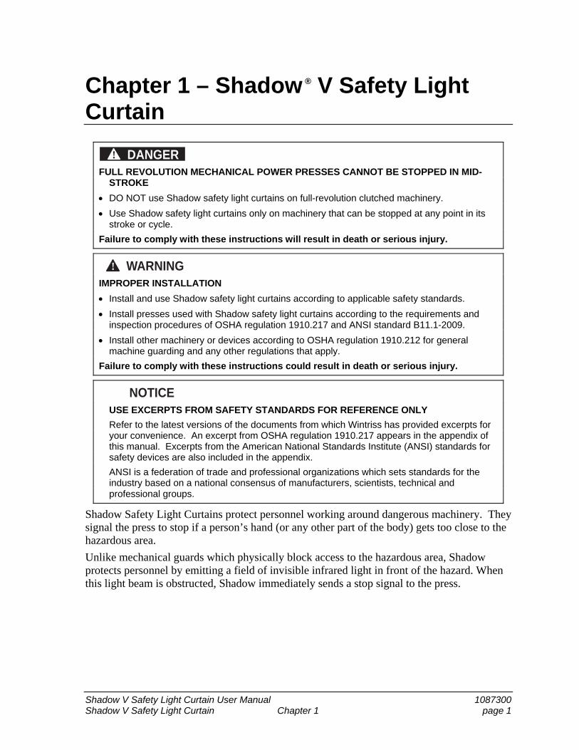
DANGER! FULL REVOLUTION MECHANICAL POWER PRESSES CANNOT BE STOPPED IN MID-
STROKE
DO NOT use Shadow safety light curtains on full-revolution clutched machinery.
Use Shadow safety light curtains only on machinery that can be stopped at any point in its stroke or cycle.
Failure to comply with these instructions will result in death or serious injury.
WARNING! IMPROPER INSTALLATION
Install and use Shadow safety light curtains according to applicable safety standards.
Install presses used with Shadow safety light curtains according to the requirements and inspection procedures of OSHA regulation 1910.217 and ANSI standard B11.1-2009.
Install other machinery or devices according to OSHA regulation 1910.212 for general machine guarding and any other regulations that apply.
Failure to comply with these instructions could result in death or serious injury.
NOTICE USE EXCERPTS FROM SAFETY STANDARDS FOR REFERENCE ONLY
Refer to the latest versions of the documents from which Wintriss has provided excerpts for your convenience. An excerpt from OSHA regulation 1910.217 appears in the appendix of this manual. Excerpts from the American National Standards Institute (ANSI) standards for safety devices are also included in the appendix.
ANSI is a federation of trade and professional organizations which sets standards for the industry based on a national consensus of manufacturers, scientists, technical and professional groups.
Shadow Safety Light Curtains protect personnel working around dangerous machinery. They signal the press to stop if a person’s hand (or any other part of the body) gets too close to the hazardous area.
Unlike mechanical guards which physically block access to the hazardous area, Shadow protects personnel by emitting a field of invisible infrared light in front of the hazard. When this light beam is obstructed, Shadow immediately sends a stop signal to the press.
1087300 Shadow V Safety Light Curtain User Manual
Page 2 Chapter 1 Shadow V Safety Light Curtain
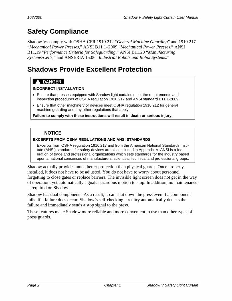
Safety Compliance Shadow Vs comply with OSHA CFR 1910.212 “General Machine Guarding” and 1910.217 “Mechanical Power Presses,” ANSI B11.1–2009 “Mechanical Power Presses,” ANSI B11.19 “Performance Criteria for Safeguarding,” ANSI B11.20 “Manufacturing Systems/Cells,” and ANSI/RIA 15.06 “Industrial Robots and Robot Systems.”
Shadows Provide Excellent Protection
DANGER! INCORRECT INSTALLATION
Ensure that presses equipped with Shadow light curtains meet the requirements and inspection procedures of OSHA regulation 1910.217 and ANSI standard B11.1-2009.
Ensure that other machinery or devices meet OSHA regulation 1910.212 for general machine guarding and any other regulations that apply.
Failure to comply with these instructions will result in death or serious injury.
NOTICE EXCERPTS FROM OSHA REGULATIONS AND ANSI STANDARDS
Excerpts from OSHA regulation 1910.217 and from the American National Standards Insti-tute (ANSI) standards for safety devices are also included in Appendix A. ANSI is a fed-eration of trade and professional organizations which sets standards for the industry based upon a national consensus of manufacturers, scientists, technical and professional groups.
Shadow actually provides much better protection than physical guards. Once properly installed, it does not have to be adjusted. You do not have to worry about personnel forgetting to close gates or replace barriers. The invisible light screen does not get in the way of operation; yet automatically signals hazardous motion to stop. In addition, no maintenance is required on Shadow.
Shadow has dual components. As a result, it can shut down the press even if a component fails. If a failure does occur, Shadow’s self-checking circuitry automatically detects the failure and immediately sends a stop signal to the press.
These features make Shadow more reliable and more convenient to use than other types of press guards.

Shadow V Safety Light Curtain User Manual 1087300
Shadow V Safety Light Curtain Chapter 1 page 3
How Shadow Works
WARNING! IMPROPER INSTALLATION
Connect the Shadow safety light curtain stop relays to the machine’s stop circuit. If you do not use the stop relays, you will not have the maximum protection afforded by these light curtains.
DO NOT attempt to connect Shadow safety light curtains to any control until you have carefully read the installation instructions.
Failure to comply with these instructions could result in death or serious injury.
WARNING! UNPROTECTED MACHINERY MAY CONTINUE TO OPERATE
Ensure that all operators know which device(s) your Shadow safety light curtain protects and which it does not. The press Shadow is wired to will stop when the light curtain is interrupted and sends a stop signal to the press. However, the associated feeds and conveyors, to which Shadow is not wired, will continue to operate after the press stops.
Failure to comply with these instructions could result in death or serious injury.
You cannot see the light field emitted by Shadow. But this invisible curtain of light automatically prevents access to hazardous areas while the press is operating.
Electricity to Light to Electricity
Shadow consists of a transmitter and receiver pair which is not a “matched set.” In other words, a transmitter will work with any same-sized receiver.
You mount each unit on the press on each side of the hazardous area as shown. Shadow can be described as an optoelectronic presence-sensing device. Presence-sensing means the light curtain can detect an object that penetrates its field and react to it (for instance, signal the press to stop when an intrusion occurs). Optoelectronic means Shadow works using light and electric current. An electric current is used to create the light beam in the transmitter. When the light strikes a phototransistor in the receiver, this action creates an electric current which signals the control circuitry that the light has been detected.
Transmitter LEDs emit light towards receiver
Transmitter LEDs emit light towards the receiver. The Shadow transmitter contains LEDs (light emitting diodes) which give off a harmless, invisible, infrared light pulse when an electrical pulse is passed through them. The Shadow receiver contains phototransistors that detect each light pulse and produce an electrical signal whenever the light pulse hits them. An invisible light barrier is formed by infrared light beams sent from the transmitter to the receiver. Shadow sends a stop command to the press when the light beam is penetrated.
1087300 Shadow V Safety Light Curtain User Manual
Page 4 Chapter 1 Shadow V Safety Light Curtain
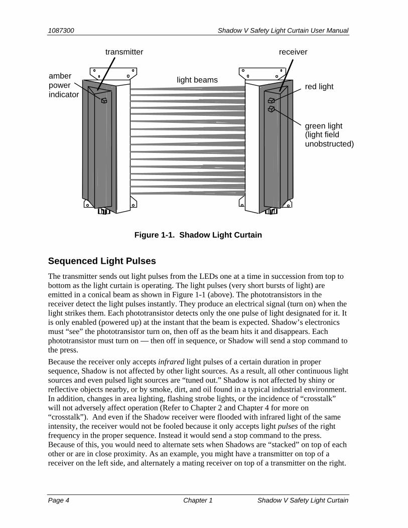
light beams
transmitter receiver
green light
amberpowerindicator
red light
(light fieldunobstructed)
Figure 1-1. Shadow Light Curtain
Sequenced Light Pulses
The transmitter sends out light pulses from the LEDs one at a time in succession from top to bottom as the light curtain is operating. The light pulses (very short bursts of light) are emitted in a conical beam as shown in Figure 1-1 (above). The phototransistors in the receiver detect the light pulses instantly. They produce an electrical signal (turn on) when the light strikes them. Each phototransistor detects only the one pulse of light designated for it. It is only enabled (powered up) at the instant that the beam is expected. Shadow’s electronics must “see” the phototransistor turn on, then off as the beam hits it and disappears. Each phototransistor must turn on — then off in sequence, or Shadow will send a stop command to the press.
Because the receiver only accepts infrared light pulses of a certain duration in proper sequence, Shadow is not affected by other light sources. As a result, all other continuous light sources and even pulsed light sources are “tuned out.” Shadow is not affected by shiny or reflective objects nearby, or by smoke, dirt, and oil found in a typical industrial environment. In addition, changes in area lighting, flashing strobe lights, or the incidence of “crosstalk” will not adversely affect operation (Refer to Chapter 2 and Chapter 4 for more on “crosstalk”). And even if the Shadow receiver were flooded with infrared light of the same intensity, the receiver would not be fooled because it only accepts light pulses of the right frequency in the proper sequence. Instead it would send a stop command to the press. Because of this, you would need to alternate sets when Shadows are “stacked” on top of each other or are in close proximity. As an example, you might have a transmitter on top of a receiver on the left side, and alternately a mating receiver on top of a transmitter on the right.
Shadow V Safety Light Curtain User Manual 1087300
Shadow V Safety Light Curtain Chapter 1 page 5
A very fast pulse
The pulsed sequence of Shadow is so fast that, where we mark time in units no smaller than a second, the effect is a continuous light field across the guarded area. You would have to move the point of your finger across an LED in the transmitter in less than 5/1000th of a second (5 ms or milliseconds) to evade the light pulses coming from that LED. Therefore in our world of seconds and minutes, the light curtain is really always there even though only one light beam is actually produced at a time. The actual light pulse lasts for only 1/100,000th of a second (10 microseconds). Consequently it does not take long to create a whole series of pulses one after the other.
Stop Signal Sent to Shadow Control Relays
We explained how the light field is created. Here is what happens when you put your hand into the field. As soon as you block one of the beams, the phototransistor reacts to the loss of light. No light means no electrical signal out from the phototransistor. This tells the control circuitry that there is an obstruction.
Control relays
The control circuitry operates two captive-contact relays in the Shadow receiver. Their contacts are connected in series to the press control’s emergency stop circuit . These relays are normally open–held closed1 . This means that the relays are always energized (contacts held closed1) when the light field is not broken. When an obstruction enters the field, Shadow’s control circuitry instantly de-energizes the relays1, which initiates a stop. The response time of Shadow, from loss of light to relay contacts open, is 30 milliseconds, (50 ms for 36” and 48” models).
Shadow and Control Reliability
WARNING! IMPROPER INSTALLATION Install Shadow safety light curtains in compliance with applicable safety regulations from the
Occupational Safety and Health Administration (OSHA) and the American National Standards Institute (ANSI). See excerpts in the appendices.
Refer to the latest revision of all applicable documents. Ensure that your installation meets the control reliability requirements of the applicable
regulations. Ensure that both Shadow control relays are used in any Shadow installation, including
connection directly to the press control’s stop circuit, to a PLC, or to other type of machine control. Wiring is explained in Chapter 2.
Read carefully and understand the installation instructions before attempting to install and wire Shadows to any control
Ensure that installation is performed by qualified personnel. Failure to comply with these instructions could result in death or serious injury.
1 Optionally available with one normally open-held closed and one normally closed-held open. When energized and with no obstruction, the relay outputs change state.
1087300 Shadow V Safety Light Curtain User Manual
Page 6 Chapter 1 Shadow V Safety Light Curtain
WARNING! UNPROTECTED MACHINERY MAY CONTINUE TO OPERATE
Ensure that all operators know which device(s) your Shadow safety light curtain protects and which it does not. The press Shadow is wired to will stop when the light curtain is interrupted and sends a stop signal to the press. However, the associated feeds and conveyors, to which Shadow is not wired, will continue to operate after the press stops.
Failure to comply with these instructions could result in death or serious injury.
Shadow is control reliable. Control reliability is a term used and defined by the Occupational Safety and Health Administration (OSHA) and the American National Standards Institute (ANSI). These agencies have issued regulations for the use of presence-sensing devices like Shadow. Both agencies require control reliability. Sometimes ANSI uses the term “control component failure” rather than control reliability. See Appendix A for more information on these regulations. Control reliability means that all critical components in the light curtain are duplicated so that if one fails, the other will still allow normal operation to stop the press. It also means that if a component failure does occur, the light curtain will immediately detect the failure and send a stop signal to the press. The light curtain will not allow operation until the repairs are made.
Control reliability is why Shadow makes an excellent machine guard. A key example is the Shadow control relays. Shadow has dual, captive-contact relays which operate simultaneously. Even if one of Shadow’s control relay contacts fails closed (contact welds shut or open), the second relay will still de-energize to send the stop signal to the press. Shadow will also detect the failed relay. It will not allow press operation until the relay is replaced. The chance of both relay contacts failing simultaneously is very small.
Indicator Lights on Shadows Shadow has three clearly visible indicator lights that tell you the Shadow condition.
Receiver indicators
The Shadow receiver has a green indicator and red indicator on its cover. The green indicator (bottom light) means the light curtain is unobstructed, and the press will be allowed to operate (control relay contacts held closed or in the unobstructed/energized state).
The red indicator means the light curtain is obstructed and the press will not be allowed to operate (control relay contacts held in the obstructed/de-energized state)2. Or it means the output relays are de-energized, which may also be due to an internal failure.
Transmitter indicator
The Shadow transmitter has one amber indicator which illuminates when power to the transmitter is on.
2 With optional 1 normally open-held closed and 1 normally closed-held open outputs, the outputs change state to the unpowered state.
Shadow V Safety Light Curtain User Manual 1087300
Shadow V Safety Light Curtain Chapter 1 page 7
Object Sensitivity Object sensitivity is the minimum diameter object that Shadow can detect. Object sensitivity for Shadow is 11/4” (3.2 cm). This means that it will detect an object of this diameter anywhere in the sensing field. Shadow light beams are on ¾” (1.9 cm) centers. An object smaller than 11/4” diameter could pass through the light field if it traveled in a path directly between the light beams. See Figure 1-1 (found earlier in this chapter).
Size and Scanning Distance Shadow is available in 12” (30.5 cm), 18” (45.7 cm), 24” (60.9 cm), 36” (91.5 cm), and 48” (121.9 cm) heights. Scanning range is up to 25 ft. (7.6 m)—up to 50 ft. (15.3 m) optional. Shadow 12” units have 16 light beams (or channels). The 18” units have 24 channels; the 24”–32 channels the 36”–48 channels; and the 48”–64 channels. See the tables at the end of this chapter for more Shadow specifications.
Shadow Is Easy to Maintain No adjustments or periodic maintenance is required. It continues working silently. You should, however, clean the windows every once in a while if your operation is particularly dusty, dirty, or smoky. A heavy build-up of dirt or oil could block a light beam and cause an inadvertent press shutdown.
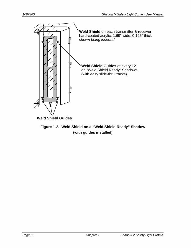
Weld Shields for Extra Protection
The operation of Shadow is not affected by smoke, dirt, or oil found in a typical industrial environment. In a more severe environment, you may need to install clear plastic shields that provide protection from weld splatter and other hazards.
Weld shields are clear plastic covers that fit on the face of the transmitter and/or receiver, as shown in the next figure. They come in kits ready for installation and can be easily replaced if they become so damaged or scratched that the light curtain no longer indicates “green” during normal operation.
1087300 Shadow V Safety Light Curtain User Manual
Page 8 Chapter 1 Shadow V Safety Light Curtain
Weld Shield on each transmitter & receiverhard-coated acrylic: 1.69" wide, 0.125" thickshown being inserted
Weld Shield Guides at every 12"on "Weld Shield Ready" Shadows(with easy slide-thru tracks)
Weld Shield Guides
Figure 1-2. Weld Shield on a “Weld Shield Ready” Shadow
(with guides installed)
Shadow V Safety Light Curtain User Manual 1087300
Shadow V Safety Light Curtain Chapter 1 page 9
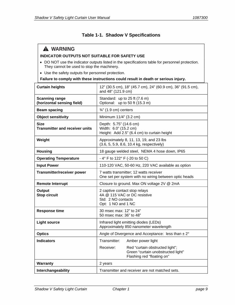
Table 1-1. Shadow V Specifications
WARNING! INDICATOR OUTPUTS NOT SUITABLE FOR SAFETY USE
DO NOT use the indicator outputs listed in the specifications table for personnel protection. They cannot be used to stop the machinery.
Use the safety outputs for personnel protection.
Failure to comply with these instructions could result in death or serious injury.
Curtain heights 12” (30.5 cm), 18” (45.7 cm), 24” (60.9 cm), 36” (91.5 cm), and 48” (121.9 cm)
Scanning range (horizontal sensing field)
Standard: up to 25 ft (7.6 m) Optional: up to 50 ft (15.3 m)
Beam spacing ¾” (1.9 cm) centers
Object sensitivity Minimum 11/4” (3.2 cm)
Size Transmitter and receiver units
Depth: 5.75” (14.6 cm) Width: 6.0” (15.2 cm) Height: Add 2.5” (6.4 cm) to curtain height
Weight Approximately 8, 11, 13, 19, and 23 lbs (3.6, 5, 5.9, 8.6, 10.4 kg, respectively)
Housing 18 gauge welded steel, NEMA 4 hose down, IP65
Operating Temperature - 4° F to 122° F (-20 to 50 C)
Input Power 110-120 VAC, 50-60 Hz, 220 VAC available as option
Transmitter/receiver power 7 watts transmitter; 12 watts receiver One set per system with no wiring between optic heads
Remote Interrupt Closure to ground. Max ON voltage 2V @ 2mA
Output Stop circuit
2 captive contact stop relays 4A @ 115 VAC or DC resistive Std: 2 NO contacts Opt: 1 NO and 1 NC
Response time 30 msec max: 12” to 24” 50 msec max: 36” to 48”
Light source Infrared light emitting diodes (LEDs) Approximately 850 nanometer wavelength
Optics Angle of Divergence and Acceptance: less than ± 2°
Indicators Transmitter: Amber power light
Receiver: Red “curtain obstructed light”; Green “curtain unobstructed light” Flashing red “floating on”
Warranty 2 years
Interchangeability Transmitter and receiver are not matched sets.
1087300 Shadow V Safety Light Curtain User Manual
Page 10 Chapter 1 Shadow V Safety Light Curtain
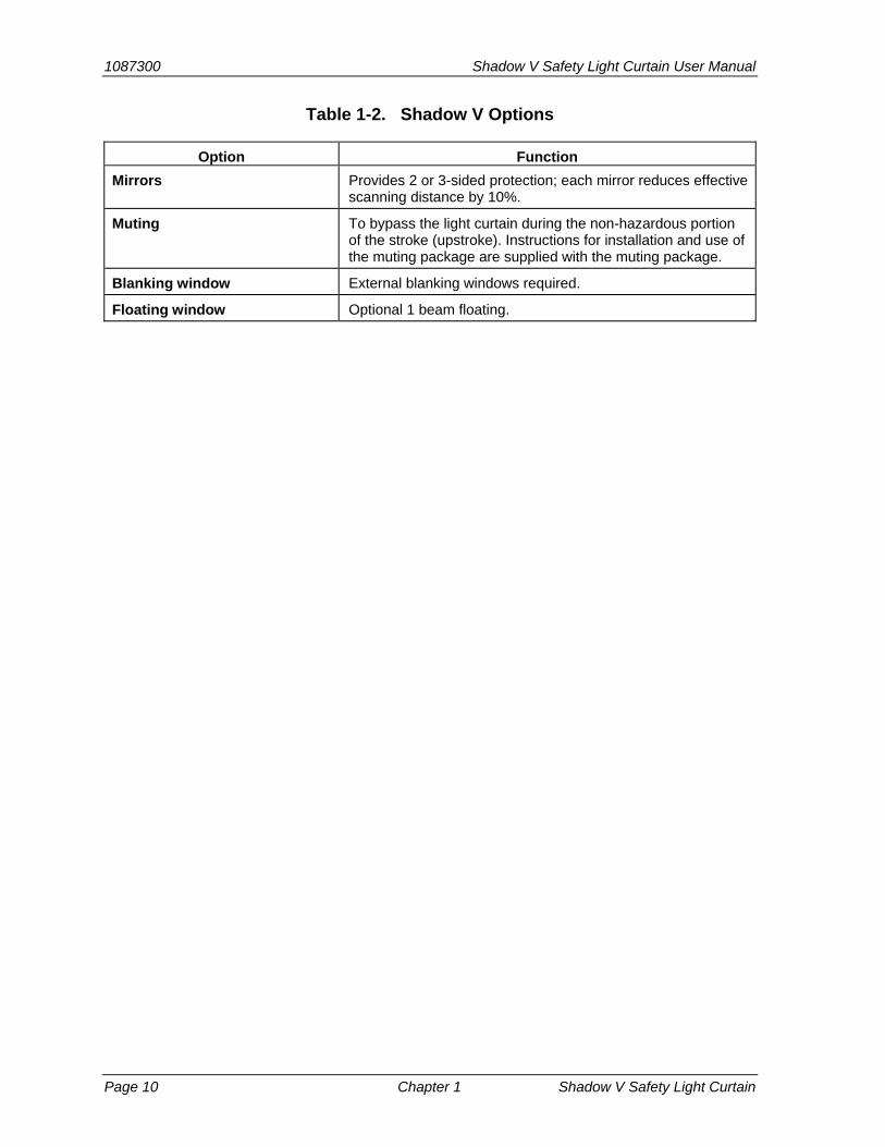
Table 1-2. Shadow V Options
Option Function
Mirrors Provides 2 or 3-sided protection; each mirror reduces effective scanning distance by 10%.
Muting To bypass the light curtain during the non-hazardous portion of the stroke (upstroke). Instructions for installation and use of the muting package are supplied with the muting package.
Blanking window External blanking windows required.
Floating window Optional 1 beam floating.
Shadow V Safety Light Curtain User Manual 1087300 Installation and Checkout Chapter 2 page 11
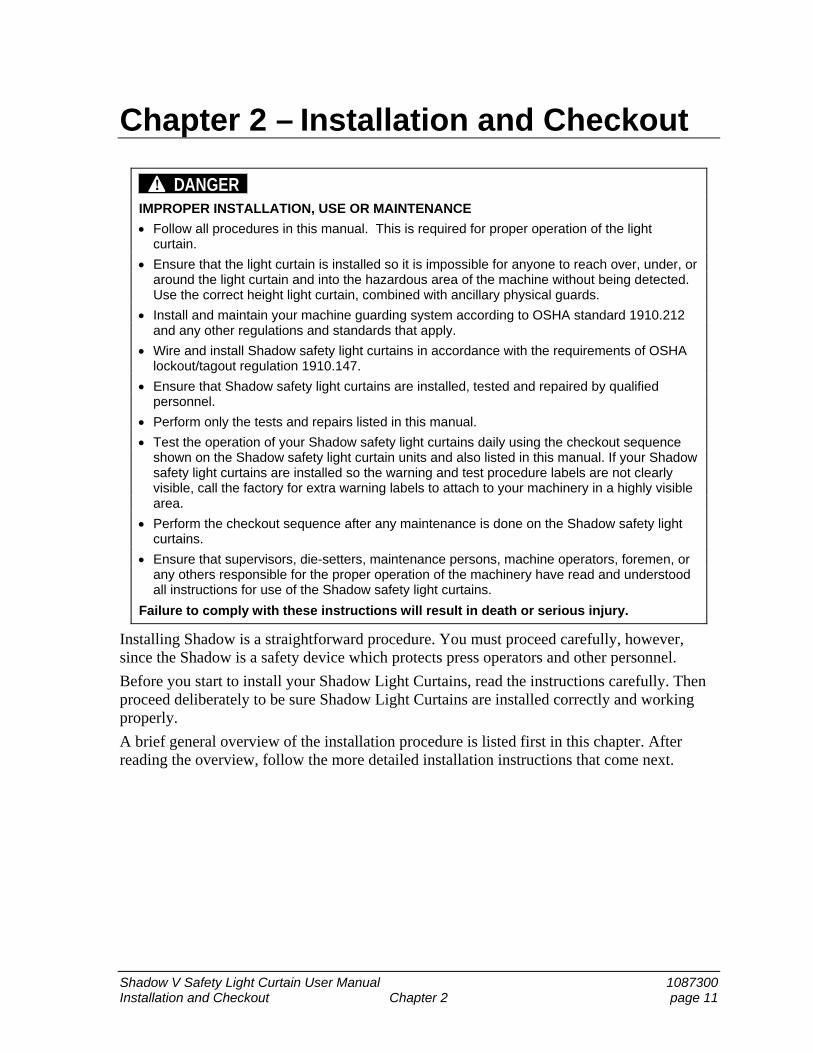
Chapter 2 – Installation and Checkout
DANGER! IMPROPER INSTALLATION, USE OR MAINTENANCE
Follow all procedures in this manual. This is required for proper operation of the light curtain.
Ensure that the light curtain is installed so it is impossible for anyone to reach over, under, or around the light curtain and into the hazardous area of the machine without being detected. Use the correct height light curtain, combined with ancillary physical guards.
Install and maintain your machine guarding system according to OSHA standard 1910.212 and any other regulations and standards that apply.
Wire and install Shadow safety light curtains in accordance with the requirements of OSHA lockout/tagout regulation 1910.147.
Ensure that Shadow safety light curtains are installed, tested and repaired by qualified personnel.
Perform only the tests and repairs listed in this manual.
Test the operation of your Shadow safety light curtains daily using the checkout sequence shown on the Shadow safety light curtain units and also listed in this manual. If your Shadow safety light curtains are installed so the warning and test procedure labels are not clearly visible, call the factory for extra warning labels to attach to your machinery in a highly visible area.
Perform the checkout sequence after any maintenance is done on the Shadow safety light curtains.
Ensure that supervisors, die-setters, maintenance persons, machine operators, foremen, or any others responsible for the proper operation of the machinery have read and understood all instructions for use of the Shadow safety light curtains.
Failure to comply with these instructions will result in death or serious injury.
Installing Shadow is a straightforward procedure. You must proceed carefully, however, since the Shadow is a safety device which protects press operators and other personnel.
Before you start to install your Shadow Light Curtains, read the instructions carefully. Then proceed deliberately to be sure Shadow Light Curtains are installed correctly and working properly.
A brief general overview of the installation procedure is listed first in this chapter. After reading the overview, follow the more detailed installation instructions that come next.
1087300 Shadow V Safety Light Curtain User Manual
Page 12 Chapter 2 Installation and Checkout
Installation Overview Read this overview before beginning the installation procedures that follow. It will familiarize you with the steps required to install a Shadow.
Overview of Steps Necessary to Install Shadow
Calculating the safety distance
All press safeguarding devices, including Shadow, must be located at the correct safety distance from the pinch point or hazardous area. This distance allows enough time for Shadow to react, and the press to stop before an intrusion, like the operator’s hand, reaches the pinch point.
The pinch point is the area of the press where moving parts can cause injury. The safety distance can be calculated precisely using the formula explained in the section “Calculating Safety Distance.”
Preparing the Mounting Location for Shadow
A mounting location is selected. Rigid mounting brackets are fabricated and attached to your press. Brackets are used to bring the Shadow Light Curtains out to the proper safety distance and to allow for proper alignment.
The light curtain must be installed so it is impossible for anyone to reach over, under, or around the light curtain and into the hazardous area of the machine without being detected. This is accomplished with the proper height light curtain, combined with ancillary physical guards.
Wiring, Aligning and Mounting Shadow
The Shadow Light Curtains are mounted to the brackets, wired into your press’s control circuitry, then aligned.
Ensuring That the Shadow Is Working Properly
A checkout sequence is performed after installation to ensure that the Shadow units are working properly.
Correct Light Curtain and Safeguarding Installation
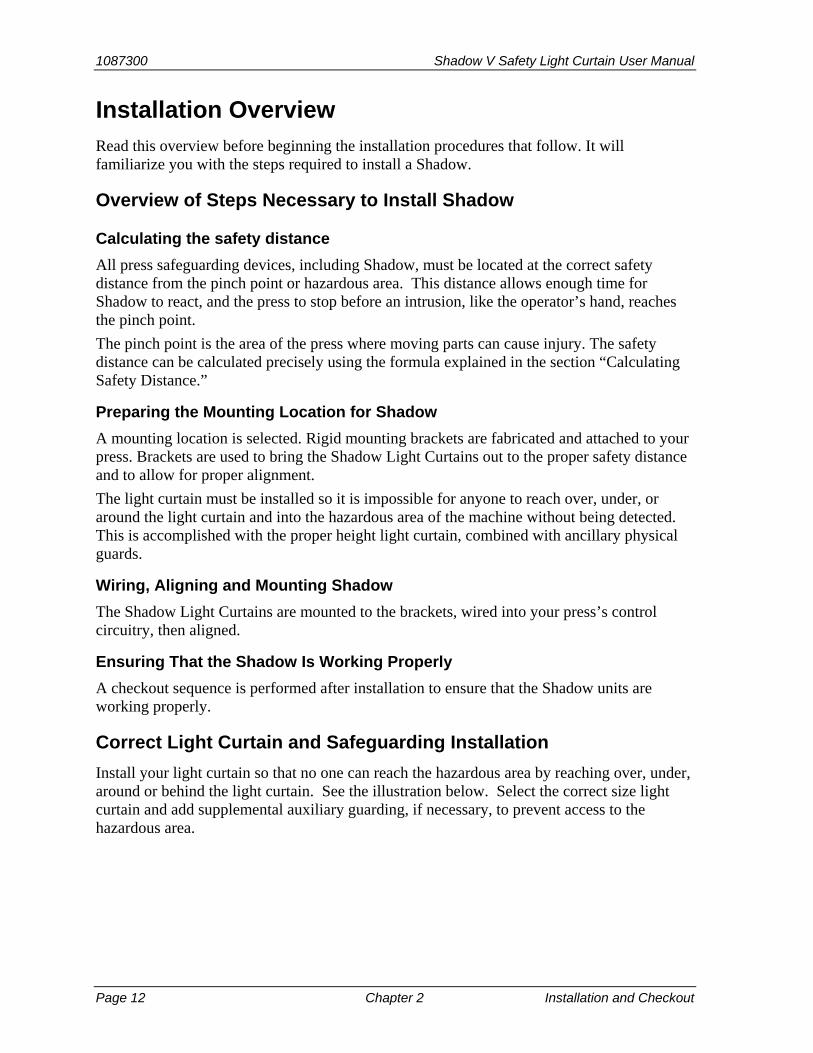
Install your light curtain so that no one can reach the hazardous area by reaching over, under, around or behind the light curtain. See the illustration below. Select the correct size light curtain and add supplemental auxiliary guarding, if necessary, to prevent access to the hazardous area.
Shadow V Safety Light Curtain User Manual 1087300
Installation and Checkout Chapter 2 page 13
Figure 2-1. Prevent Reaching Over, Under or Around a Light Curtain
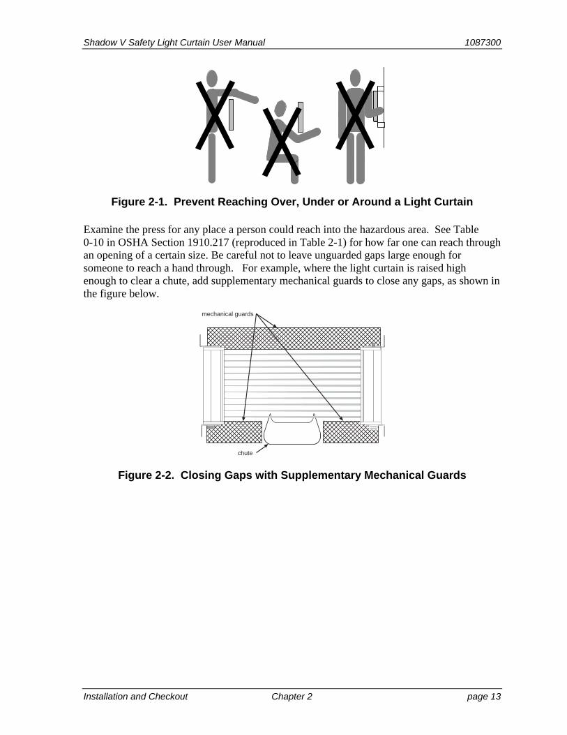
Examine the press for any place a person could reach into the hazardous area. See Table 0-10 in OSHA Section 1910.217 (reproduced in Table 2-1) for how far one can reach through an opening of a certain size. Be careful not to leave unguarded gaps large enough for someone to reach a hand through. For example, where the light curtain is raised high enough to clear a chute, add supplementary mechanical guards to close any gaps, as shown in the figure below.
mechanical guards
chute
Figure 2-2. Closing Gaps with Supplementary Mechanical Guards

1087300 Shadow V Safety Light Curtain User Manual
Page 14 Chapter 2 Installation and Checkout
Installation Procedure
DANGER! FAILURE TO PERFORM SAFETY SYSTEM TESTS
Perform the final checkout sequence below when you have completed installation of your light curtain, before operating the equipment it is connected to.
Operate your machinery only after your safety system meets all the requirements of the checkout sequence.
Perform the final checkout sequence whenever repair, maintenance or modification is performed on your light curtain or the machinery it is connected to.
Perform the “daily test” safety system checkout sequence on page 93 (in French, en Français, page 94) every day before operating any machinery connected to Shadow safety light curtains.
Failure to comply with these instructions will result in death or serious injury.
WARNING! ELECTRIC SHOCK HAZARD
Turn off and disconnect power from the Shadow safety light curtain and from the machinery it is connected to before making any wiring connections. This includes disconnecting power to the machine control and motor.
Remove all fuses and “tag out” per OSHA 1910.147 Control of Hazardous Energy (Lockout/Tagout).
Ensure that installation is performed by qualified personnel.
Failure to comply with these instructions could result in death or serious injury.
The installation procedure is divided into these steps:
Calculating the Safety Distance, page 15
Designing and Mounting Brackets, page 23
Wiring and Loosely Mounting Your Shadow Light Curtains, page 35
Aligning and Tightening Down Your Shadow Light Curtains, page 48
Diagnostic Steps to Perform Before Shadow Operation, page 50
It is a good idea to read over the complete installation procedure before starting. This will give you an idea of the materials and techniques required for making and positioning mounting brackets and aligning your Shadow Light Curtains.
Shadow V Safety Light Curtain User Manual 1087300
Installation and Checkout Chapter 2 page 15
Calculating the Safety Distance
DANGER! INCORRECT SAFETY DISTANCE
Calculate the safety distance carefully according to the instructions below, and mount your light curtain heads at least this distance from the hazardous area.
Mount your light curtain heads at least 7.5” (191 mm) from the hazardous area, regardless of the calculated safety distance.
Failure to comply with these instructions will result in death or serious injury.
DANGER! INCREASED SAFETY DISTANCE DUE TO BLANKING OR FLOATING WINDOWS
Modify the safety distance between the light curtain and the hazardous area according to the instructions in this chapter and in Chapter 3, “Floating and Blanking Windows.”
Failure to comply with these instructions will result in death or serious injury.
DANGER! INCORRECT SAFETY DISTANCE DUE TO LONGER RESPONSE TIME
Determine which model Shadow safety light curtains you have. Use the correct response time for your model light curtain in your safety distance calculations. Safety depends on your installing your light curtain at the correct safety distance from the hazardous area.
12” to 24” 30 ms response time 36” to 48” 50 ms response time
Failure to comply with these instructions will result in death or serious injury.
DANGER! STOPPING TIME TOO LONG
Use a brake monitor where a Shadow light curtain is used to protect operators whose hands are routinely exposed to a hazardous area, as required by OSHA 1910.217 © (3) (5). A brake monitor continually checks that the machine’s stopping time does not exceed a predetermined limit.
Failure to comply with these instructions will result in death or serious injury.
Shadow Light Curtains must be mounted away from the pinch point (or hazardous area) of the press at a specific distance. This distance is based on the stopping time of your press. This distance is called the safety distance. It must be calculated using a precise formula. This ensures that Shadow can send the stop signal to the press, and the press will stop, before the operator’s hand reaches the hazardous area.
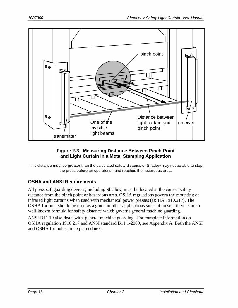
The next illustration shows how you would measure the distance between the pinch point (or hazardous area) of your press and the light curtain.
1087300 Shadow V Safety Light Curtain User Manual
Page 16 Chapter 2 Installation and Checkout
pinch point
transmitter
Distance betweenlight curtain andpinch point
One of theinvisiblelight beams
receiver
Figure 2-3. Measuring Distance Between Pinch Point and Light Curtain in a Metal Stamping Application
This distance must be greater than the calculated safety distance or Shadow may not be able to stop the press before an operator’s hand reaches the hazardous area.
OSHA and ANSI Requirements
All press safeguarding devices, including Shadow, must be located at the correct safety distance from the pinch point or hazardous area. OSHA regulations govern the mounting of infrared light curtains when used with mechanical power presses (OSHA 1910.217). The OSHA formula should be used as a guide in other applications since at present there is not a well-known formula for safety distance which governs general machine guarding.
ANSI B11.19 also deals with general machine guarding. For complete information on OSHA regulation 1910.217 and ANSI standard B11.1-2009, see Appendix A. Both the ANSI and OSHA formulas are explained next.
Shadow V Safety Light Curtain User Manual 1087300
Installation and Checkout Chapter 2 page 17
The OSHA Safety Distance Formula
DANGER! INCORRECT SAFETY DISTANCE
Calculate the safety distance carefully according to the instructions below, and mount your light curtain heads at least this distance from the hazardous area.
Mount your light curtain heads at least 7.5” (191 mm) from the hazardous area, regardless of the calculated safety distance.
Be sure your value for Ts includes the response times of all devices that react to stop the press. If your measurement of stop time does not include response time of the press control, light curtain, and any other devices that react to stop the press, the safety distance will be too short.
Failure to comply with these instructions will result in death or serious injury.
DANGER! STOPPING TIME TOO LONG
Use a brake monitor where a Shadow light curtain is used to protect operators whose hands are routinely exposed to a hazardous area, as required by OSHA 1910.217 © (3) (5). A brake monitor continually checks that the machine’s stopping time does not exceed a predetermined limit.
Failure to comply with these instructions will result in death or serious injury.
The OSHA safety distance formula as specified in OSHA regulation 1910.217 is explained below. As noted earlier, Wintriss recommends you use the American National Standards Institute formula for calculating safety distance because it contains more factors that allow you to calculate the safety distance more precisely. The ANSI formula is explained in the next section.
Here is the OSHA safety distance formula as specified in OSHA 1910.217:
Ds = 63 inches/second x Ts
63 inches-per-second is the OSHA-recommended hand-speed constant.
Ds is OSHA safety distance in inches
Ds = 63 x Ts
Ts is the stopping time of the press in seconds, measured at approximately 90° of crankshaft rotation (or at maximum velocity). Ts must include: all components that are involved in stopping the press; response time of the press control that activates the brake and response time of the light curtain (30 ms for Shadow 12”, 18”, and 24”; 50 ms for 36” and 48” models); plus response time of other devices if also involved in stopping the press.
Since some increase in stop time can invariably be anticipated due to clutch/brake system deterioration, a percentage factor must also be added to the actual measured stop time of your press when determining your safety distance.
A percentage factor of 20 percent is recommended for machines with new brakes or brakes in good condition; a percentage factor of 10 percent is recommended for presses with older
1087300 Shadow V Safety Light Curtain User Manual
Page 18 Chapter 2 Installation and Checkout
brakes. This is because the stopping time for older brakes will be longer due to wear. Therefore, you add less time for older brakes.
Example: Calculating the safety distance using the OSHA formula
The OSHA formula for finding safety distance is:
Ds = 63 inches/sec. x Ts
We will use a stop time of 0.190 seconds for this example. This includes reaction time of all devices noted above in signaling the press to stop except the response time of the light curtain. Next we will add in Shadow response time 0.030 seconds (30 msec).
Then:
Ts = 0.190 sec. + 0.030 sec. (Shadow response time) Ts = 0.220
Now, we will calculate safety distance:
Ds = 63 in/sec x Ts
Ds = 63 x 0.220
Ds = 13.9 in.
Shadow must be mounted more than 13.9 inches from the hazardous area, using the OSHA formula.

Shadow V Safety Light Curtain User Manual 1087300
Installation and Checkout Chapter 2 page 19
The ANSI Safety Distance Formula
DANGER! INCORRECT SAFETY DISTANCE
Calculate the safety distance carefully according to the instructions below, and mount your light curtain heads at least this distance from the hazardous area.
Mount your light curtain heads at least 7.5” (191 mm) from the hazardous area, regardless of the calculated safety distance.
Be sure your value for Ts includes the response times of all devices that react to stop the press. If your measurement of stop time does not include response time of the press control, light curtain, and any other devices that react to stop the press, the safety distance will be too short.
Failure to comply with these instructions will result in death or serious injury.
DANGER! STOPPING TIME TOO LONG
Use a brake monitor where a Shadow light curtain is used to protect operators whose hands are routinely exposed to a hazardous area, as required by OSHA 1910.217 © (3) (5). A brake monitor continually checks that the machine’s stopping time does not exceed a predetermined limit.
Failure to comply with these instructions will result in death or serious injury.
This is the ANSI B11.1 safety distance formula that Wintriss recommends:
Ds = 63 x (Ts + Tc + Tr + Tbm) + Dpf
Ds is the ANSI safety distance in inches.
K (which shows an actual value of 63 in the previous equation) is the OSHA-recommended hand-speed constant. The hand-speed constant (equaling 63 inches-per-second) indicates how far you could theoretically move your hand and arm in one second.
It is very similar to OSHA’s formula, except that it takes more details (such as response times, brake monitoring setting, and depth penetration factor) into account. Ts, Tc, and Tr are the worst case response times of the press Ts, the control Tc, and the light curtain Tr. Response time for the Shadow is 30 ms (50 ms for 36” and 48” models).Ts is the worst case stopping time of a press in seconds.
Tc is the response time of the press control. This is the time it takes for the control to activate the machine’s brake.
Tr is the response time of the light curtain. Response time for the Shadow is 30 milliseconds (50 ms for 36” and 48” models).
Tbm is the additional stopping time of the press allowed by the brake monitor. The brake monitor you use with your press control stops the press when the stop time set on it is exceeded. This means excessive brake wear has occurred. It is time for repair. The brake gradually wears until the limit is reached.
1087300 Shadow V Safety Light Curtain User Manual
Page 20 Chapter 2 Installation and Checkout
Tbm allows you to account for brake wear. You add the extra time allowed by the brake
monitor to Tc and Ts. In other words:
Tbm = brake monitor setting — (Tc + Ts)
Now the gradual increase in stopping time as the brake wear is accounted for right up to the limit.
What if you did not account for brake wear? The safety distance would be right at the time you measured stop time. But as the brake gradually wore, safety distance would be too short for proper operator protection.
See instructions for your brake monitor to determine the proper setting. Generally, the setting is 120% of the measured stopping time (Tc + Ts) when your brakes are new. It is 110% of stopping time (Ts + Tc) for older brakes.
(The stopping time for older brakes will be longer due to wear. Therefore, you add less time for older brakes. This way, the brake monitor setting comes out approximately the same whether the brakes are new or old).
Dpf is the depth penetration factor. This is a measure of how far an object, such as an op-erator’s hand, can move through the light curtain before the light curtain reacts. Dpf is related to the object sensitivity. Object sensitivity is the smallest diameter object that Shadow will detect anywhere in its field. Object sensitivity (S) for Shadow is 1.25” (3.2 cm), with beam centers of ¾” (1.9 cm) and Dpf = 3.3” (8.4 cm).
For Shadow with one beam blanked, refer to the section “Blanking Windows Affect Safety Distance,” page 56.
Example: Calculating the safety distance using the ANSI formula
Here is an example of how to use the ANSI formula to calculate safety distance (Ds):
First take a look again at the formula we must use:
Ds = K x (Ts + Tc + Tr + Tbm) + Dpf
Let’s use these numbers for our variables in the formula:
K (hand speed constant) = 63 inches per second (set by OSHA)
Ts + Tc = 0.190 sec.
We include Ts and Tc together because many stop time measuring devices measure stopping time of the press control as well as the stopping time of the clutch/brake mechanism. In this case the brake monitor setting is 0.228 seconds.
Tr = 0.030 sec. (response time of Shadow)
Tbm = 0.228 sec. (brake monitor setting) – 0.190 sec = 0.038 sec.
Dpf = 3.3
Now let’s put our numbers into the formula:
Ds = K x (Ts + Tc + Tr + Tbm) + Dpf
Ds = 63 x (0.190 + .030 + .038) + 3.3
Ds = (63 x .258) + 3.3
Ds = 16.3 + 3.3
Shadow V Safety Light Curtain User Manual 1087300
Installation and Checkout Chapter 2 page 21
Ds = 19.6”
The distance the light curtain must be mounted from the pinch point in our example is 19.6”. When using the formula, be sure to do all calculations in this order:
(1) Add Ts + Tc + Tr + Tbm first.
(2) Multiply the result by 63.
(3) Add this result to Dpf. This is Ds.
If you do not follow this order, your safety distance calculation will be incorrect.
Perimeter Guarding
For perimeter safeguarding, there is another consideration — walking speed combined with the hand speed. This is because personnel might be walking while simultaneously reaching into a safeguarded area. Although there is no commonly accepted “walking speed constant” like the “hand constant,” you might use ergonomic tables or possibly even 100 inches per second, which is a conservative European “speed constant.” For perimeter guarding, the formula would be:
Ds = (100) x (Ts + Tc + Tr + Tbm) + Dpf
Blanking Windows Affect Safety Distance
If you use a blanking window or floating blanking window, safety distance is affected, because you are changing the sensitivity of the light curtain. Remember, the minimum size that Shadow can sense is an object 1.25” (3.17 cm) in diameter. Anything smaller might fit between two light beams. This diameter (1.25”) is called the object sensitivity of the light curtain.
The ANSI safety distance formula states that if the object sensitivity increases, the safety distance must also increase. Using blanking windows will require moving the light curtain farther back from the hazardous area (increased Dpf ). The rule for increasing safety distance is this: Add 2.6” (6.6 cm) to the safety distance for every window used, up to 2 beams maximum.
If the blanked area is entirely blocked by a fixture such that operator intrusion would be impossible, you do not need to change the safety distance. For instance, you might have a work table that protrudes into the light field but takes up the whole unprotected space between the transmitter and receiver.
If the blanked area is not obstructed physically, the object sensitivity is 2” wide (5.08 cm) (2” = 11/4” + ¾”). The Dpf equals 5.9” (15 cm), which is 2.6” more than an unblanked Shadow (2.6” = 5.9 - 3.3).
You can blank more than one beam of the light curtain by adding slave windows to the master window. Always remove blanking windows when they are no longer required.
Blanking more than two beams can create a large, unprotected passageway through the light curtain. If this passageway is not completely filled by a fixture, the operator would be subject to a particularly dangerous working environment.
1087300 Shadow V Safety Light Curtain User Manual
Page 22 Chapter 2 Installation and Checkout
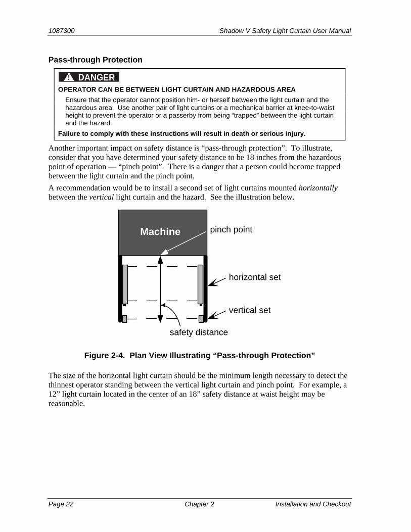
Pass-through Protection
DANGER! OPERATOR CAN BE BETWEEN LIGHT CURTAIN AND HAZARDOUS AREA
Ensure that the operator cannot position him- or herself between the light curtain and the hazardous area. Use another pair of light curtains or a mechanical barrier at knee-to-waist height to prevent the operator or a passerby from being “trapped” between the light curtain and the hazard.
Failure to comply with these instructions will result in death or serious injury.
Another important impact on safety distance is “pass-through protection”. To illustrate, consider that you have determined your safety distance to be 18 inches from the hazardous point of operation — “pinch point”. There is a danger that a person could become trapped between the light curtain and the pinch point.
A recommendation would be to install a second set of light curtains mounted horizontally between the vertical light curtain and the hazard. See the illustration below.
pinch point
horizontal set
vertical set
safety distance
Machine
Figure 2-4. Plan View Illustrating “Pass-through Protection”
The size of the horizontal light curtain should be the minimum length necessary to detect the thinnest operator standing between the vertical light curtain and pinch point. For example, a 12” light curtain located in the center of an 18” safety distance at waist height may be reasonable.

Shadow V Safety Light Curtain User Manual 1087300
Installation and Checkout Chapter 2 page 23
Height Considerations
DANGER! OPERATOR CAN BE BETWEEN LIGHT CURTAIN AND HAZARDOUS AREA
Ensure that the operator cannot position him- or herself between the light curtain and the hazardous area. Use another pair of light curtains or a mechanical barrier at knee-to-waist height to prevent the operator or a passerby from being “trapped” between the light curtain and the hazard.
Failure to comply with these instructions will result in death or serious injury.
Once you have determined the correct safety distance, you need to select the proper light curtain height. The Shadow V Light Curtain comes in various sizes ranging from 12” to 48”. Shadow must be installed so it is impossible for anyone to reach over, under, or around the light curtain and into the hazardous area of the press without being detected. This is accomplished with the proper height Shadow Light Curtain, combined with ancillary physical guards.
Designing and Mounting Brackets
Once you have calculated the correct safety distance, you mount your Shadow Light Curtains at this distance from the nearest pinch point (or other hazardous area of the press). This step lists all the information and dimensions you need to know to do a good job in designing and mounting brackets.
The topics covered include:
1. What requirements you must meet when choosing your mounting location.
2. How to design and mount brackets so Shadow can be easily aligned.
3. Maximum openings for side guards used with Shadow Light Curtains for three-sided guarding.
4. Mounting Shadow Light Curtains with mirrors.
5. Mounting Shadow Light Curtains upside down.
6. Avoiding crosstalk when mounting 2 sets of Shadows
A careful reading of this material will ensure that you will not have any trouble mounting and aligning your Shadow Light Curtains in steps 3 and 4. After you read this material, design and mount your brackets.
Mounting Location Requirements
DANGER! OPERATOR CAN BE BETWEEN LIGHT CURTAIN AND HAZARDOUS AREA
Ensure that the operator cannot position him- or herself between the light curtain and the hazardous area. Use another pair of light curtains or a mechanical barrier at knee-to-waist height to prevent the operator or a passerby from being “trapped” between the light curtain and the hazard.
Failure to comply with these instructions will result in death or serious injury.
1087300 Shadow V Safety Light Curtain User Manual
Page 24 Chapter 2 Installation and Checkout
When choosing the mounting location, you must make sure the location meets these requirements:
1. Shadow units must always be installed so that it is impossible for anyone to reach over, under, or around the light curtain and into the hazardous area of the press without being detected.
2. The units must be protected from pathways used by forklifts, die carts, and other material-handling equipment.
3. The mounting location must allow unobstructed access to the point-of-operation.
4. Shadow must be located at an adequate safety distance from the point of operation (pinch point) to allow time for the press to stop once the light curtain is interrupted.
Calculating safety distance is explained in the section “Calculating Safety Distance.”
5. Every route to the machine’s pinch point or hazardous area must be guarded. Shadow units by themselves provide press guarding on one side. Mirrors used with Shadow Light Curtains can provide 3-sided protection by “bending” the light curtain around the hazardous point-of-operation. When Shadow mirrors are not used in conjunction with the light curtain, however, other guarding means (such as mechanical side-guards) must be substituted for them, in accordance with OSHA/ANSI guidelines.
How to Design and Mount Brackets
You mount Shadow Light Curtains to your press using the Shadow flanges on top and bottom of each unit. Shadow Light Curtains are mounted to brackets attached to your press. Wintriss does not supply brackets with Shadow Light Curtains. You must supply your own.
This section lists the factors you must take into account when designing and mounting brackets. If you need more specific information for your particular press, do not hesitate to call our technical services department for help.
If you cannot make your own brackets, contact Wintriss Tech. Support for information on where you can buy various types of brackets.
Shape and Size of Brackets
Brackets must meet these three conditions.
1. They must provide a rigid mounting surface for the Shadow units.
2. They must bring the Shadow units out far enough away from the point of operation to exceed the calculated safety distance.
3. They must allow the light curtain to be easily aligned.
It does not matter which type of brackets you design as long as they meet these three conditions. Of course, brackets must be made from rigid material like steel.
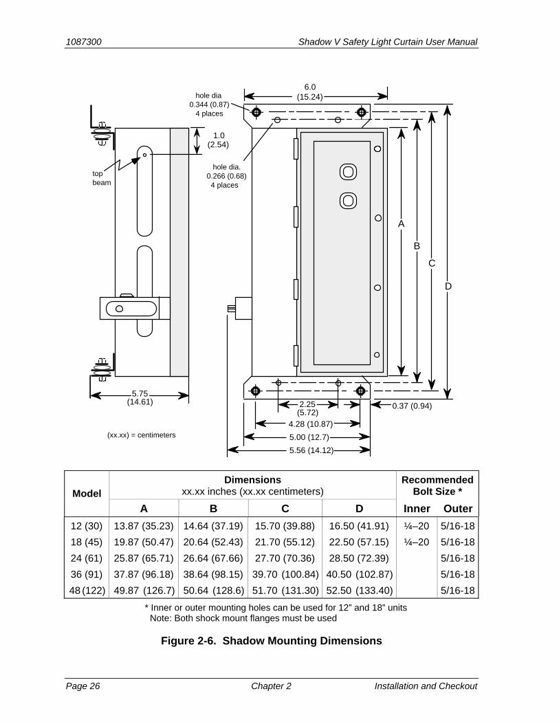
The illustration (Figure 2-5) on the next page shows several types of brackets you can make. It gives you an idea of just some of the types used. See Figure 2-6 for Shadow’s layout and hole dimensions.

Shadow V Safety Light Curtain User Manual 1087300
Installation and Checkout Chapter 2 page 25
Making brackets to fit your press
Brackets have to be configured to fit the shape of your particular press. For instance, on some presses, you can mount angle iron (L-shaped) brackets directly to a sidewall of the press (see Figure 2-10).
On other machinery, like bending rolls, you may have to mount Shadow Light Curtains from the bed or platform of the press.
If you must mount brackets on the bolster, choose your location carefully. Make sure the brackets do not prevent dies from being removed from the press.
Long angle iron type of bracket. Here one unit mounts right on one large bracket.
Wedge-shaped bracket good for mounting units to bed or wall of machinery.
Box type brackets.
L-shaped brackets with side supports for rigidity
Figure 2-5. Brackets for Shadow
Brackets used must be made of strong, thick steel so mounting is rigid. These are only a few of the designs you can make or use. They are shown only to give you an idea of what brackets are. Many
different designs are possible as long as all mounting requirements are met.
1087300 Shadow V Safety Light Curtain User Manual
Page 26 Chapter 2 Installation and Checkout
2.25
4.28 (10.87)
5.00 (12.7)
5.56 (14.12)
6.0
5.75
0.37 (0.94)(5.72)
(15.24)
(14.61)
(xx.xx) = centimeters
hole dia.0.266 (0.68) 4 places
hole dia0.344 (0.87) 4 places
1.0(2.54)
A
B
C
D
topbeam
Model Dimensions
xx.xx inches (xx.xx centimeters) Recommended
Bolt Size *
A B C D Inner Outer
12 (30) 13.87 (35.23) 14.64 (37.19) 15.70 (39.88) 16.50 (41.91) ¼–20 5/16-18
18 (45) 19.87 (50.47) 20.64 (52.43) 21.70 (55.12) 22.50 (57.15) ¼–20 5/16-18
24 (61) 25.87 (65.71) 26.64 (67.66) 27.70 (70.36) 28.50 (72.39) 5/16-18
36 (91) 37.87 (96.18) 38.64 (98.15) 39.70 (100.84) 40.50 (102.87) 5/16-18
48 (122) 49.87 (126.7) 50.64 (128.6) 51.70 (131.30) 52.50 (133.40) 5/16-18
* Inner or outer mounting holes can be used for 12” and 18” units Note: Both shock mount flanges must be used
Figure 2-6. Shadow Mounting Dimensions

Shadow V Safety Light Curtain User Manual 1087300
Installation and Checkout Chapter 2 page 27
Shadow Light Curtains must be attached at both ends to prevent vibration that would cause the units to go out of alignment. It is acceptable to mount Shadow brackets to your press at one end only. However, your bracket must be designed so it attaches to both the top and bottom Shadow shock mounts.
Mounting Shadow Light Curtains without brackets
You can mount your Shadow Light Curtains directly to a vertical wall or column of your press if the location meets all mounting requirements.
Installing Brackets with Alignment in Mind
The bracket design must allow adjustment of the Shadow units once they are mounted. Shadow Light Curtains may have to be moved slightly up or down or rocked slightly to one side or the other to align them once they are mounted (you will see why when we discuss alignment).
You can use shims on the mounting bolts for the sideways adjusting and a method like grooves in the mounting brackets to allow slight up and down movement. As you will see below, the movement required is very slight.
What alignment means
The alignment procedure is explained in the section “Aligning and tightening down your Shadow Light Curtains.” But you need to know what alignment means now to do a good job of installing brackets.
For Shadow to operate properly, each infrared light beam emitted horizontally from the Shadow transmitter must be detected by each phototransistor in the receiver.
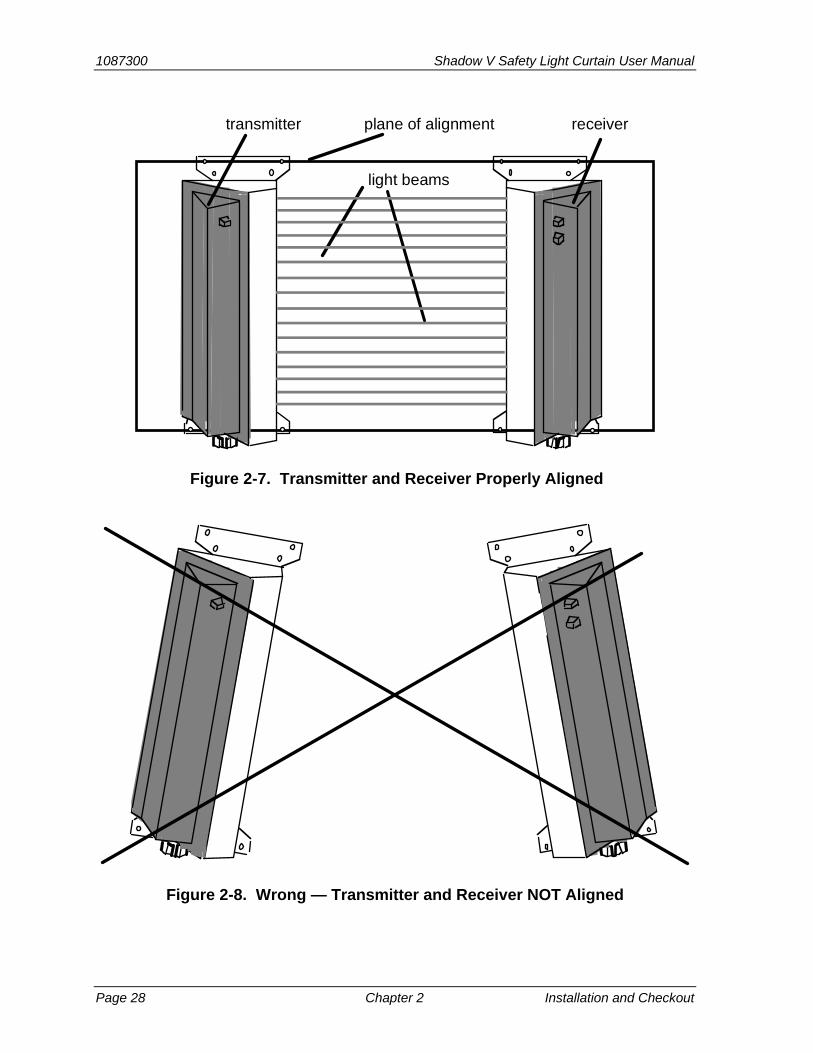
The phototransistors (PTs) as well as the emitters of light (LEDs) are located inside the plastic window slots of each unit. You cannot see them, but their location matches the numbers next to the windows. Each LED (light emitter) must match up with its opposite PT (phototransistor) when the Shadow Light Curtains are mounted as shown in Figure 2-7. Therefore, Shadow units must be mounted in the same plane. Figure 2-8 illustrates how NOT to mount your light curtains.
They do not have to be perfectly aimed because some misalignment is allowed.
As shown in Figure 2-7, light beams are actually cone shaped. Each conical light beam must “hit” its opposite phototransistor. As long as the phototransistor is anywhere within the beam, Shadow units are in alignment. You can see that units do not have to be perfectly in line. Of course, you cannot see the light beams during alignment. You know Shadow Light Curtains are aligned when the green light on the Shadow receiver is on.
You should always try to mount Shadow brackets as precisely as possible. Then, the alignment procedure in the section “Aligning and tightening down your Shadow Light Curtains” will be easy. Also note that Shadow Light Curtains do not have to be mounted vertically (although this is certainly the most common method). They can be mounted at any angle as long as they are in the same plane.
1087300 Shadow V Safety Light Curtain User Manual
Page 28 Chapter 2 Installation and Checkout
light beams
plane of alignmenttransmitter receiver
Figure 2-7. Transmitter and Receiver Properly Aligned
Figure 2-8. Wrong — Transmitter and Receiver NOT Aligned
Shadow V Safety Light Curtain User Manual 1087300
Installation and Checkout Chapter 2 page 29
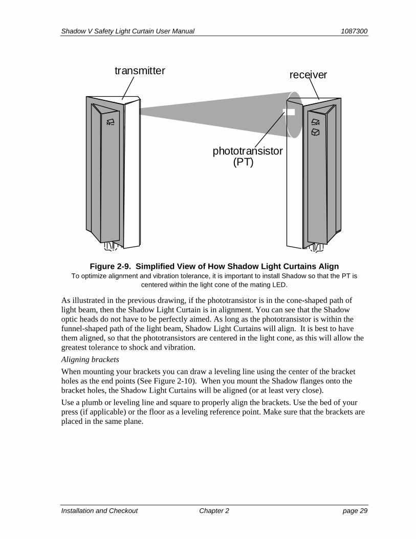
transmitter receiver
phototransistor(PT)
Figure 2-9. Simplified View of How Shadow Light Curtains Align To optimize alignment and vibration tolerance, it is important to install Shadow so that the PT is
centered within the light cone of the mating LED.
As illustrated in the previous drawing, if the phototransistor is in the cone-shaped path of light beam, then the Shadow Light Curtain is in alignment. You can see that the Shadow optic heads do not have to be perfectly aimed. As long as the phototransistor is within the funnel-shaped path of the light beam, Shadow Light Curtains will align. It is best to have them aligned, so that the phototransistors are centered in the light cone, as this will allow the greatest tolerance to shock and vibration.
Aligning brackets
When mounting your brackets you can draw a leveling line using the center of the bracket holes as the end points (See Figure 2-10). When you mount the Shadow flanges onto the bracket holes, the Shadow Light Curtains will be aligned (or at least very close).
Use a plumb or leveling line and square to properly align the brackets. Use the bed of your press (if applicable) or the floor as a leveling reference point. Make sure that the brackets are placed in the same plane.
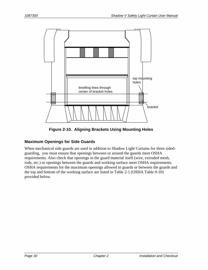
1087300 Shadow V Safety Light Curtain User Manual
Page 30 Chapter 2 Installation and Checkout
levelling lines through center of bracket holes
bracket
top mounting holes
Figure 2-10. Aligning Brackets Using Mounting Holes
Maximum Openings for Side Guards
When mechanical side guards are used in addition to Shadow Light Curtains for three sided-guarding, you must ensure that openings between or around the guards meet OSHA requirements. Also check that openings in the guard material itself (wire, extruded mesh, rods, etc.) or openings between the guards and working surface meet OSHA requirements. OSHA requirements for the maximum openings allowed in guards or between the guards and the top and bottom of the working surface are listed in Table 2-1 (OSHA Table 0-10) provided below.
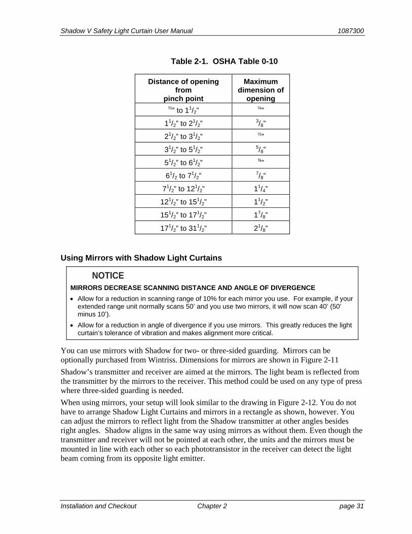
Shadow V Safety Light Curtain User Manual 1087300
Installation and Checkout Chapter 2 page 31
Table 2-1. OSHA Table 0-10
Distance of opening from
pinch point
Maximum dimension of
opening ½” to 11/2”
¼”
11/2” to 21/2” 3/8”
21/2” to 31/2” ½”
31/2” to 51/2” 5/8”
51/2” to 61/2” ¾”
61/2 to 71/2” 7/8”
71/2” to 121/2” 11/4”
121/2” to 151/2” 11/2”
151/2” to 171/2” 17/8”
171/2” to 311/2” 21/8”
Using Mirrors with Shadow Light Curtains
NOTICE MIRRORS DECREASE SCANNING DISTANCE AND ANGLE OF DIVERGENCE
Allow for a reduction in scanning range of 10% for each mirror you use. For example, if your extended range unit normally scans 50’ and you use two mirrors, it will now scan 40’ (50’ minus 10’).
Allow for a reduction in angle of divergence if you use mirrors. This greatly reduces the light curtain’s tolerance of vibration and makes alignment more critical.
You can use mirrors with Shadow for two- or three-sided guarding. Mirrors can be optionally purchased from Wintriss. Dimensions for mirrors are shown in Figure 2-11
Shadow’s transmitter and receiver are aimed at the mirrors. The light beam is reflected from the transmitter by the mirrors to the receiver. This method could be used on any type of press where three-sided guarding is needed.
When using mirrors, your setup will look similar to the drawing in Figure 2-12. You do not have to arrange Shadow Light Curtains and mirrors in a rectangle as shown, however. You can adjust the mirrors to reflect light from the Shadow transmitter at other angles besides right angles. Shadow aligns in the same way using mirrors as without them. Even though the transmitter and receiver will not be pointed at each other, the units and the mirrors must be mounted in line with each other so each phototransistor in the receiver can detect the light beam coming from its opposite light emitter.
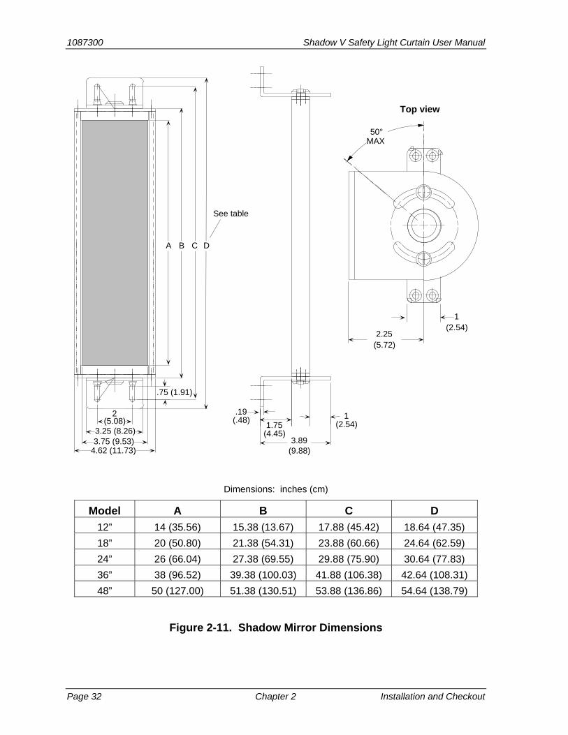
1087300 Shadow V Safety Light Curtain User Manual
Page 32 Chapter 2 Installation and Checkout
.19(.48)
1.75(4.45)
1(2.54)
.75 (1.91)
See table
50°MAX
1(2.54)
Top view
3.89(9.88)
2.25(5.72)
4.62 (11.73)3.75 (9.53)3.25 (8.26)
2(5.08)
A B C D
Dimensions: inches (cm)
Model A B C D
12” 14 (35.56) 15.38 (13.67) 17.88 (45.42) 18.64 (47.35)
18” 20 (50.80) 21.38 (54.31) 23.88 (60.66) 24.64 (62.59)
24” 26 (66.04) 27.38 (69.55) 29.88 (75.90) 30.64 (77.83)
36” 38 (96.52) 39.38 (100.03) 41.88 (106.38) 42.64 (108.31)
48” 50 (127.00) 51.38 (130.51) 53.88 (136.86) 54.64 (138.79)
Figure 2-11. Shadow Mirror Dimensions

Shadow V Safety Light Curtain User Manual 1087300
Installation and Checkout Chapter 2 page 33
receiver
light beams
transmitter corner mirrors
Figure 2-12. Using Shadow Light Curtains with Mirrors, Example
Mounting Shadow Light Curtains Upside Down
There is nothing inherent in the design of Shadow units that prevents them from being mounted upside down. If you are mounting your Shadow system this way for any reason, both units (transmitter and receiver) must be inverted. Shadow Light Curtains can also be mounted at any angle as long as they are in the same plane. Vertical mounting is the easiest.
Avoiding Crosstalk When Mounting 2 Sets of Shadows
Because the receiver only accepts infrared light pulses of a certain duration in proper sequence, Shadow is not affected by other light sources. All other continuous light sources and even pulsed light sources are “tuned out”, and Shadow continues to work. Also, changes in area lighting, flashing strobe lights, or the incidence of “crosstalk” will not adversely affect operation. Even if the Shadow receiver were flooded with infrared light of the same intensity, the receiver would not be fooled because it only accepts light pulses of the right frequency in proper sequence. Instead it would send a stop command to the press.
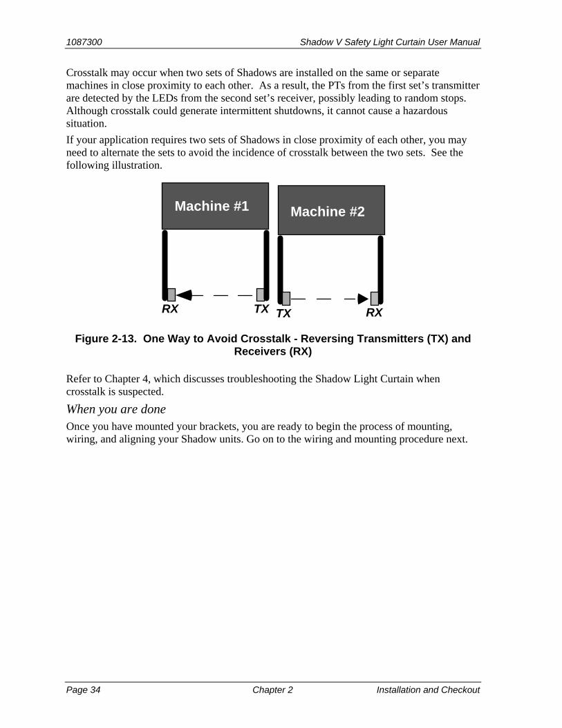
1087300 Shadow V Safety Light Curtain User Manual
Page 34 Chapter 2 Installation and Checkout
Crosstalk may occur when two sets of Shadows are installed on the same or separate machines in close proximity to each other. As a result, the PTs from the first set’s transmitter are detected by the LEDs from the second set’s receiver, possibly leading to random stops. Although crosstalk could generate intermittent shutdowns, it cannot cause a hazardous situation.
If your application requires two sets of Shadows in close proximity of each other, you may need to alternate the sets to avoid the incidence of crosstalk between the two sets. See the following illustration.
Machine #1
TXRX
Machine #2
TX RX
Figure 2-13. One Way to Avoid Crosstalk - Reversing Transmitters (TX) and Receivers (RX)
Refer to Chapter 4, which discusses troubleshooting the Shadow Light Curtain when crosstalk is suspected.
When you are done Once you have mounted your brackets, you are ready to begin the process of mounting, wiring, and aligning your Shadow units. Go on to the wiring and mounting procedure next.

Shadow V Safety Light Curtain User Manual 1087300
Installation and Checkout Chapter 2 page 35
Wiring and Loosely Mounting Your Shadow Light Curtains
DANGER! FULL REVOLUTION MECHANICAL POWER PRESSES AND OTHER MACHINES
CANNOT BE STOPPED IN MID-STROKE OR MID-CYCLE
DO NOT use Shadow safety light curtains on full-revolution clutched machinery or other equipment that cannot be stopped at any point in its stroke or cycle.
Use Shadow safety light curtains only on machinery that can be stopped at any point in its stroke or cycle.
Failure to comply with these instructions will result in death or serious injury.
DANGER! MACHINE MAY CONTINUE TO MOVE AFTER INTRUSION
Ensure that Shadow is wired to the emergency stop circuitry of the hazardous machinery.
Ensure that any stop initiated by the light curtain is an immediate stop, one that occurs immediately after the stop signal is sent to the machinery. (If the light curtain is wired by mistake to the top-stop circuitry, the press continue its stroke until it reaches the top of the stroke, even after an intrusion or obstruction is detected.)
Failure to comply with these instructions will result in death or serious injury.
WARNING! ELECTRIC SHOCK HAZARD
Ensure that the power source is off before you make any wiring connections.
Disconnect power from the machinery it is connected to before making any wiring connections. This includes disconnecting power to the machine control and motor.
Ensure that all procedures are performed by qualified personnel.
Failure to comply with these instructions could result in death or serious injury.
WARNING! STOP CIRCUITS WIRED INCORRECTLY
Wire the light curtain to your press control circuit so the stop signal from the light curtain stops the machine immediately in all modes of operation, including inch.
Failure to comply with these instructions could result in death or serious injury.
This section covers how to wire your Shadow Light Curtains and loosely mount them to your press. Shadow Light Curtains must be wired into your press such that any Shadow-initiated stop will be an emergency stop.
Wiring the Shadow into your press’s emergency stop or equivalent circuitry ensures that whenever an obstruction or intrusion has been indicated, the press will stop as quickly as its clutch/brake system (or other system) will permit.
Wiring is a straightforward and simple procedure. Both transmitter and receiver are wired independently to a 115 VAC 50-60 Hz single phase power source, and the output circuit from

1087300 Shadow V Safety Light Curtain User Manual
Page 36 Chapter 2 Installation and Checkout
the Shadow receiver unit is wired to the machine’s stop circuit. (Note: A specially-modified Shadow can be used with 220 VAC, 50 Hz.)
How to wire the Shadow transmitter and receiver is explained next.
Wiring and Loosely Mounting Your Transmitter:
WARNING! ELECTRIC SHOCK HAZARD
Turn off and disconnect power from the Shadow safety light curtain and from the machinery it is connected to before making any wiring connections. This includes disconnecting power to the machine control and motor.
Ensure that installation is performed by qualified personnel.
Ensure that the AC power source is off before you make any wiring connections.
Complete all installation procedures before connecting wires to the AC power source.
Failure to comply with these instructions could result in death or serious injury.
1. Put the transmitter on a bench or table in front of you. (Each Shadow unit is labeled “transmitter” or “receiver”). Remove all the screws on the cover. This is a hinged cover which will swing open when the screws are removed. See below. (The number of screws on the cover depends on the length of your unit).
coverscrews
transmitter
Figure 2-14. Removing Screws from Shadow Cover
2. Swing the cover open. At the bottom near the conduit connection nuts, you will see the connector for your wiring. This is a combination terminal strip and connector (see the next illustration). Remove the female part (the top L section) by pulling it away from the base. This is the part to which you will connect wiring.
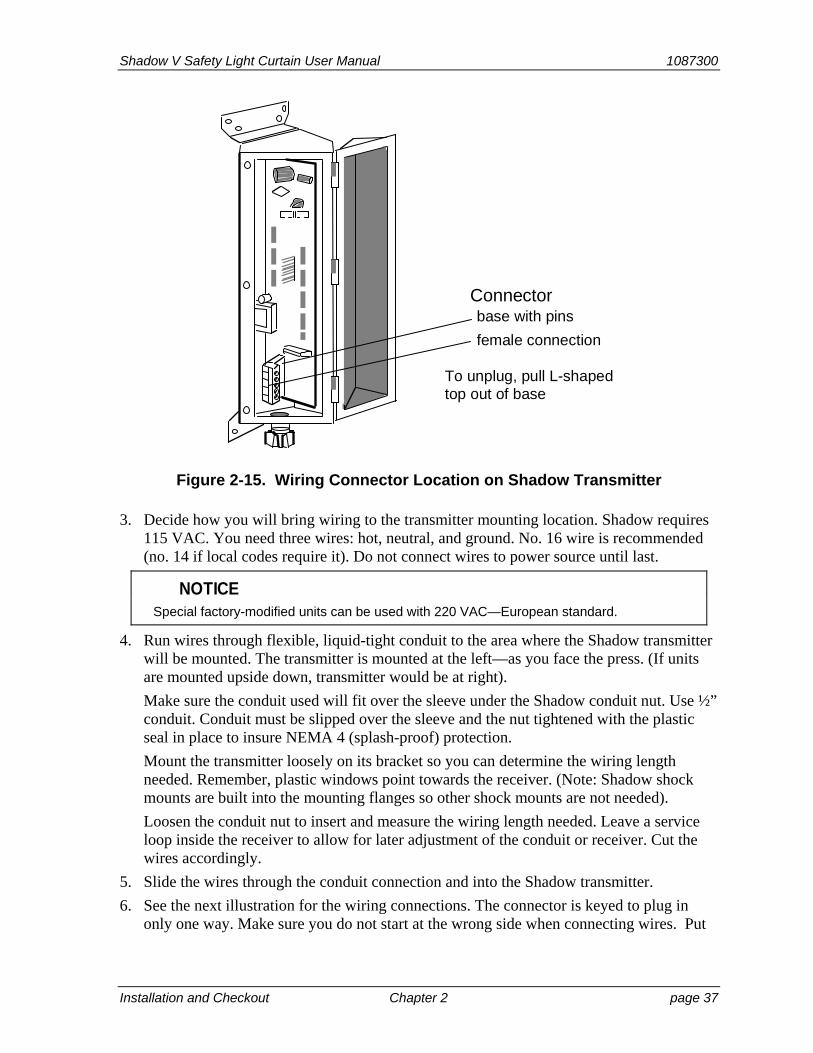
Shadow V Safety Light Curtain User Manual 1087300
Installation and Checkout Chapter 2 page 37
Connectorbase with pins
female connection
To unplug, pull L-shapedtop out of base
Figure 2-15. Wiring Connector Location on Shadow Transmitter
3. Decide how you will bring wiring to the transmitter mounting location. Shadow requires 115 VAC. You need three wires: hot, neutral, and ground. No. 16 wire is recommended (no. 14 if local codes require it). Do not connect wires to power source until last.
NOTICE Special factory-modified units can be used with 220 VAC—European standard.
4. Run wires through flexible, liquid-tight conduit to the area where the Shadow transmitter will be mounted. The transmitter is mounted at the left—as you face the press. (If units are mounted upside down, transmitter would be at right).
Make sure the conduit used will fit over the sleeve under the Shadow conduit nut. Use ½” conduit. Conduit must be slipped over the sleeve and the nut tightened with the plastic seal in place to insure NEMA 4 (splash-proof) protection.
Mount the transmitter loosely on its bracket so you can determine the wiring length needed. Remember, plastic windows point towards the receiver. (Note: Shadow shock mounts are built into the mounting flanges so other shock mounts are not needed).
Loosen the conduit nut to insert and measure the wiring length needed. Leave a service loop inside the receiver to allow for later adjustment of the conduit or receiver. Cut the wires accordingly.
5. Slide the wires through the conduit connection and into the Shadow transmitter.
6. See the next illustration for the wiring connections. The connector is keyed to plug in only one way. Make sure you do not start at the wrong side when connecting wires. Put
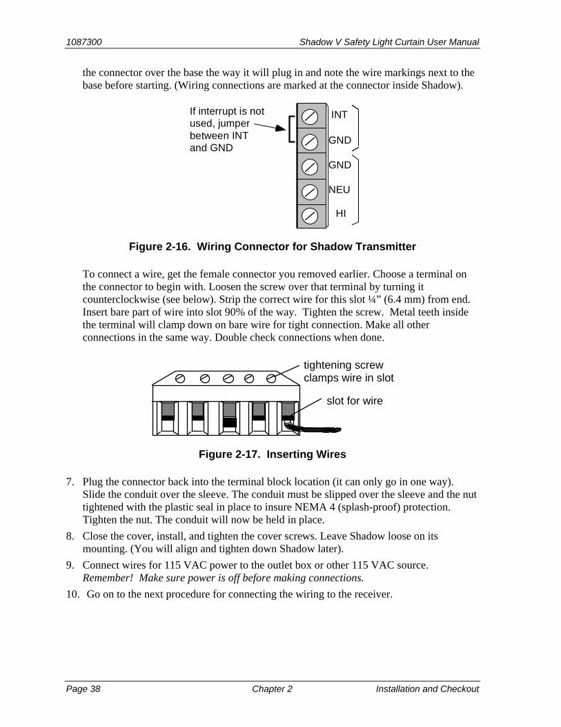
1087300 Shadow V Safety Light Curtain User Manual
Page 38 Chapter 2 Installation and Checkout
the connector over the base the way it will plug in and note the wire markings next to the base before starting. (Wiring connections are marked at the connector inside Shadow).
If interrupt is notused, jumperbetween INTand GND
INT
GND
GND
NEU
HI
Figure 2-16. Wiring Connector for Shadow Transmitter
To connect a wire, get the female connector you removed earlier. Choose a terminal on the connector to begin with. Loosen the screw over that terminal by turning it counterclockwise (see below). Strip the correct wire for this slot ¼” (6.4 mm) from end. Insert bare part of wire into slot 90% of the way. Tighten the screw. Metal teeth inside the terminal will clamp down on bare wire for tight connection. Make all other connections in the same way. Double check connections when done.
slot for wire
tightening screw clamps wire in slot
Figure 2-17. Inserting Wires
7. Plug the connector back into the terminal block location (it can only go in one way). Slide the conduit over the sleeve. The conduit must be slipped over the sleeve and the nut tightened with the plastic seal in place to insure NEMA 4 (splash-proof) protection. Tighten the nut. The conduit will now be held in place.
8. Close the cover, install, and tighten the cover screws. Leave Shadow loose on its mounting. (You will align and tighten down Shadow later).
9. Connect wires for 115 VAC power to the outlet box or other 115 VAC source. Remember! Make sure power is off before making connections.
10. Go on to the next procedure for connecting the wiring to the receiver.
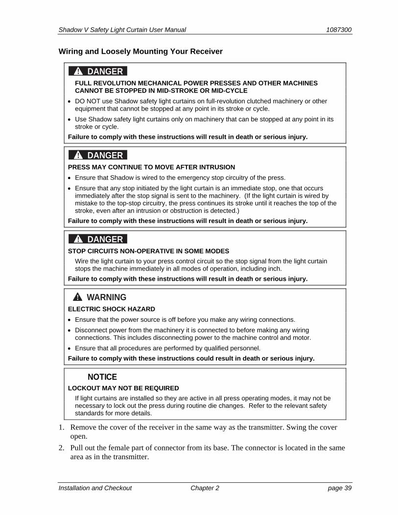
Shadow V Safety Light Curtain User Manual 1087300
Installation and Checkout Chapter 2 page 39
Wiring and Loosely Mounting Your Receiver
DANGER! FULL REVOLUTION MECHANICAL POWER PRESSES AND OTHER MACHINES
CANNOT BE STOPPED IN MID-STROKE OR MID-CYCLE
DO NOT use Shadow safety light curtains on full-revolution clutched machinery or other equipment that cannot be stopped at any point in its stroke or cycle.
Use Shadow safety light curtains only on machinery that can be stopped at any point in its stroke or cycle.
Failure to comply with these instructions will result in death or serious injury.
DANGER! PRESS MAY CONTINUE TO MOVE AFTER INTRUSION
Ensure that Shadow is wired to the emergency stop circuitry of the press.
Ensure that any stop initiated by the light curtain is an immediate stop, one that occurs immediately after the stop signal is sent to the machinery. (If the light curtain is wired by mistake to the top-stop circuitry, the press continues its stroke until it reaches the top of the stroke, even after an intrusion or obstruction is detected.)
Failure to comply with these instructions will result in death or serious injury.
DANGER! STOP CIRCUITS NON-OPERATIVE IN SOME MODES
Wire the light curtain to your press control circuit so the stop signal from the light curtain stops the machine immediately in all modes of operation, including inch.
Failure to comply with these instructions will result in death or serious injury.
WARNING! ELECTRIC SHOCK HAZARD
Ensure that the power source is off before you make any wiring connections.
Disconnect power from the machinery it is connected to before making any wiring connections. This includes disconnecting power to the machine control and motor.
Ensure that all procedures are performed by qualified personnel.
Failure to comply with these instructions could result in death or serious injury.
NOTICE LOCKOUT MAY NOT BE REQUIRED
If light curtains are installed so they are active in all press operating modes, it may not be necessary to lock out the press during routine die changes. Refer to the relevant safety standards for more details.
1. Remove the cover of the receiver in the same way as the transmitter. Swing the cover open.
2. Pull out the female part of connector from its base. The connector is located in the same area as in the transmitter.
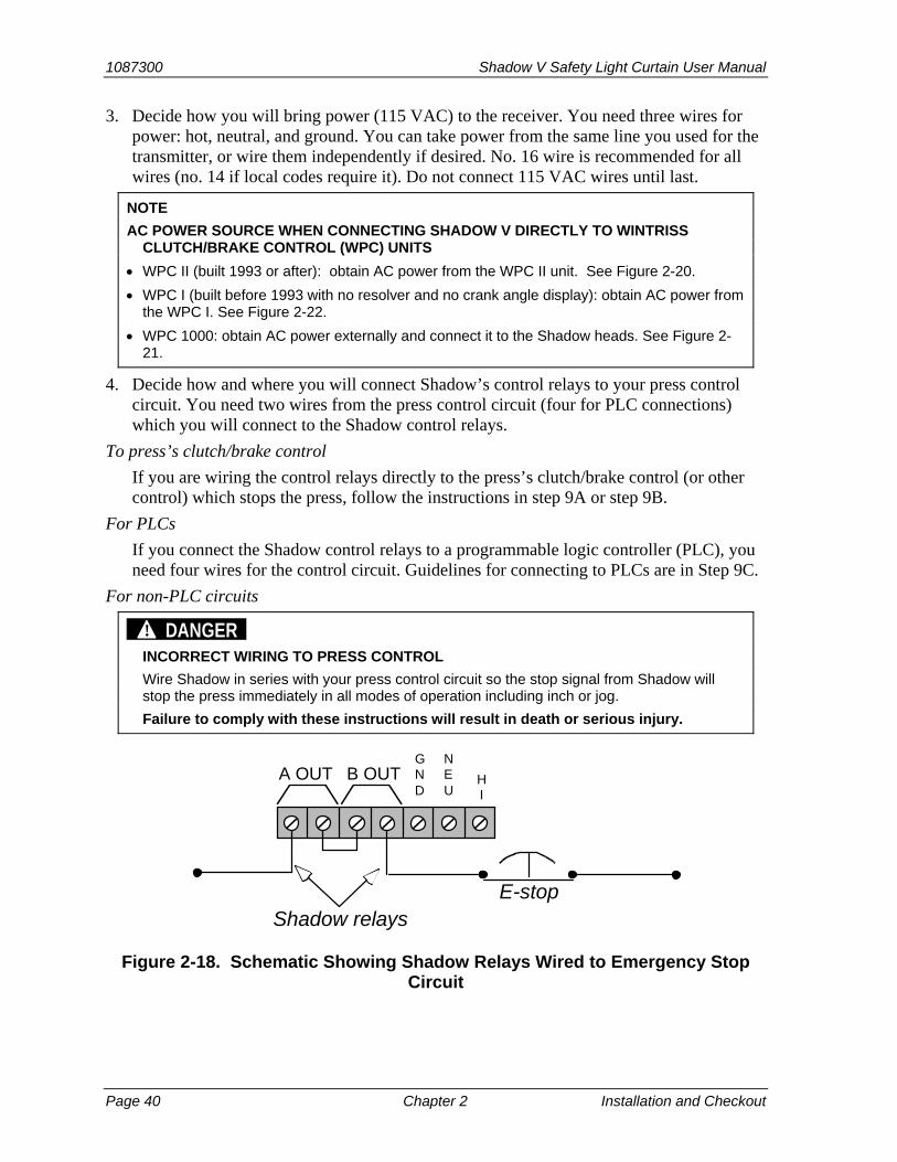
1087300 Shadow V Safety Light Curtain User Manual
Page 40 Chapter 2 Installation and Checkout
3. Decide how you will bring power (115 VAC) to the receiver. You need three wires for power: hot, neutral, and ground. You can take power from the same line you used for the transmitter, or wire them independently if desired. No. 16 wire is recommended for all wires (no. 14 if local codes require it). Do not connect 115 VAC wires until last.
NOTE
AC POWER SOURCE WHEN CONNECTING SHADOW V DIRECTLY TO WINTRISS CLUTCH/BRAKE CONTROL (WPC) UNITS
WPC II (built 1993 or after): obtain AC power from the WPC II unit. See Figure 2-20.
WPC I (built before 1993 with no resolver and no crank angle display): obtain AC power from the WPC I. See Figure 2-22.
WPC 1000: obtain AC power externally and connect it to the Shadow heads. See Figure 2-21.
4. Decide how and where you will connect Shadow’s control relays to your press control circuit. You need two wires from the press control circuit (four for PLC connections) which you will connect to the Shadow control relays.
To press’s clutch/brake control
If you are wiring the control relays directly to the press’s clutch/brake control (or other control) which stops the press, follow the instructions in step 9A or step 9B.
For PLCs
If you connect the Shadow control relays to a programmable logic controller (PLC), you need four wires for the control circuit. Guidelines for connecting to PLCs are in Step 9C.
For non-PLC circuits
DANGER! INCORRECT WIRING TO PRESS CONTROL
Wire Shadow in series with your press control circuit so the stop signal from Shadow will stop the press immediately in all modes of operation including inch or jog.
Failure to comply with these instructions will result in death or serious injury.
E-stopShadow relays
GND
NEU
HI
A OUT B OUT
Figure 2-18. Schematic Showing Shadow Relays Wired to Emergency Stop Circuit
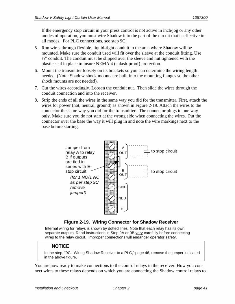
Shadow V Safety Light Curtain User Manual 1087300
Installation and Checkout Chapter 2 page 41
If the emergency stop circuit in your press control is not active in inch/jog or any other modes of operation, you must wire Shadow into the part of the circuit that is effective in all modes. For PLC connections, see step 9C.
5. Run wires through flexible, liquid-tight conduit to the area where Shadow will be mounted. Make sure the conduit used will fit over the sleeve at the conduit fitting. Use ½” conduit. The conduit must be slipped over the sleeve and nut tightened with the plastic seal in place to insure NEMA 4 (splash-proof) protection.
6. Mount the transmitter loosely on its brackets so you can determine the wiring length needed. (Note: Shadow shock mounts are built into the mounting flanges so the other shock mounts are not needed).
7. Cut the wires accordingly. Loosen the conduit nut. Then slide the wires through the conduit connection and into the receiver.
8. Strip the ends of all the wires in the same way you did for the transmitter. First, attach the wires for power (hot, neutral, ground) as shown in Figure 2-19. Attach the wires to the connector the same way you did for the transmitter. The connector plugs in one way only. Make sure you do not start at the wrong side when connecting the wires. Put the connector over the base the way it will plug in and note the wire markings next to the base before starting.
Jumper fromrelay A to relayB if outputsare tied inseries with E-stop circuit
OUT
A
OUTB
HI
NEU
GND
to stop circuit
to stop circuit(for 1 NO/1 NCas per step 9Cremovejumper!)
Figure 2-19. Wiring Connector for Shadow Receiver Internal wiring for relays is shown by dotted lines. Note that each relay has its own separate outputs. Read instructions in Step 9A or 9B very carefully before connecting wires to the relay circuit. Improper connections will endanger operator safety.
NOTICE In the step, “9C. Wiring Shadow Receiver to a PLC,” page 46, remove the jumper indicated
in the above figure.
You are now ready to make connections to the control relays in the receiver. How you con-nect wires to these relays depends on which you are connecting the Shadow control relays to.
1087300 Shadow V Safety Light Curtain User Manual
Page 42 Chapter 2 Installation and Checkout
9A. Wiring Shadow Receiver with 2 N/O Outputs to Press Control Circuit, below
9B. Wiring Shadow to WPC II, WPC 1000 or WPC I Wintriss Press Control, below
9C. Wiring Shadow Receiver to a PLC, page 46
9A. Wiring Shadow Receiver with 2 N/O Outputs to Press Control Circuit
DANGER! INCORRECT WIRING
Connect both relays in series when wired directly to the press control. If you wired only one relay to the control circuit, there would be no backup if the control contact of the one relay were to weld closed, and the Shadow could not cut off power to the control circuit when the light curtain was interrupted, and the press would not stop.
Failure to comply with these instructions will result in death or serious injury.
When wiring the receiver directly to the press control circuit, the control relays must be wired in series. To connect wiring:
1. First make sure the jumper shown in Figure 2-19 is in place. This jumper is installed at the factory. It connects the two control relays in series.
2. Connect wires from the press control circuit to the other two relay outputs. In Figure 2-19 they are the first and fourth screw from left. This circuit now connects both relays in series. You attach wires in the same way as the transmitter. Leave a service loop inside the receiver to allow for later adjustment of the conduit or receiver.
3. Double check all connections. Remember, relays must be wired in series. This is extremely important. After wiring the receiver, go to step 10.
9B. Wiring Shadow to WPC II, WPC 1000 or WPC I Wintriss Press Control
DANGER! INCORRECT WIRING
Connect both relays in series when wired directly to the press control. If you wired only one relay to the control circuit, there would be no backup if the control contact of the one relay were to weld closed, and the Shadow could not cut off power to the control circuit when the light curtain was interrupted, and the press would not stop.
Failure to comply with these instructions will result in death or serious injury.
WPC II (WPC built 1993 or after): See wiring diagram, Figure 2-20.
WPC 1000: See wring diagram, Figure 2-21. Note that you must connect AC power directly to the Shadow heads.
WPC I (older version WPC, manufactured before 1993, which has no resolver, uses a rotary limit switch and does not have a crank-angle display): See wiring diagram, Figure 2-22.
After wiring the receiver, go to step 10.
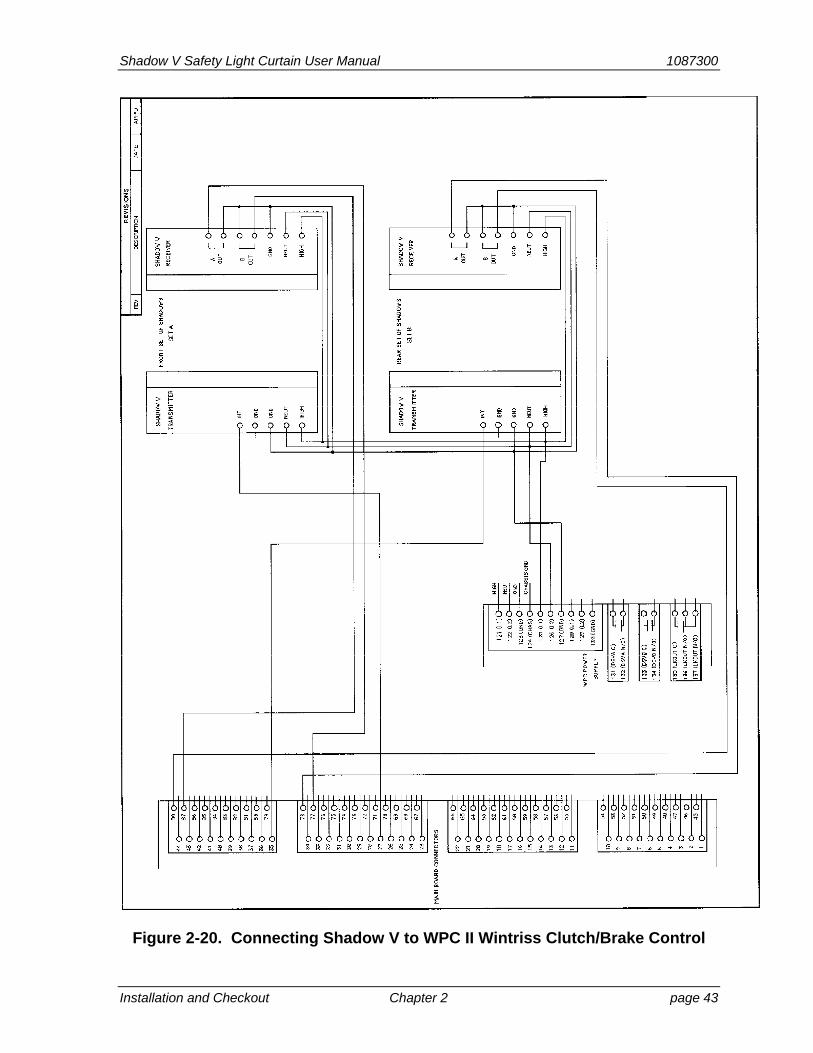
Shadow V Safety Light Curtain User Manual 1087300
Installation and Checkout Chapter 2 page 43
Figure 2-20. Connecting Shadow V to WPC II Wintriss Clutch/Brake Control
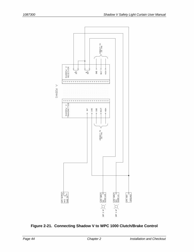
1087300 Shadow V Safety Light Curtain User Manual
Page 44 Chapter 2 Installation and Checkout
Figure 2-21. Connecting Shadow V to WPC 1000 Clutch/Brake Control

Shadow V Safety Light Curtain User Manual 1087300
Installation and Checkout Chapter 2 page 45
SH
AD
OW
V T
RA
NS
MIT
TE
R
HIGH
NEUTGNDGND
INT
SH
AD
OW
V R
EC
EIV
ER
HIGH
NEU
GND
BOUT
AOUT
12
10
8
6
4
2
13
11
9
7
5
3
1
P1
ED
GE
CO
NN
EC
TO
R/
TE
RM
INA
L S
TR
IP
TB1
GN
D
NE
UT
HIG
H
Wintriss Press Control
Wintriss Press Control
Figure 2-22. Connecting Shadow V to WPC I Wintriss Press Control
(WPC manufactured before 1993 with no resolver and no crank angle display)

1087300 Shadow V Safety Light Curtain User Manual
Page 46 Chapter 2 Installation and Checkout
9C. Wiring Shadow Receiver to a PLC
DANGER! INCORRECT WIRING TO A PLC
Ensure that the light curtain control is properly wired to your PLC.
Follow the guidelines in the applicable ANSI standard, ANSI B11.1. The guidelines below serve as a reminder of the importance of connecting your light curtain correctly when using a PLC.
Be aware that the details of wiring and programming the PLC are solely your responsibility, and not that of Wintriss.
Use a single safety PLC or multiple non-safety PLCs.
Failure to comply with these instructions will result in death or serious injury.
CAUTION TERMINAL BLOCK TB4 WIRED INCORRECTLY
Wire stop circuits to the upper level of terminal block TB4, not the lower level. If you wire to the lower level, this could damage components on the circuit board.
Failure to comply with these instructions could result in property damage.
When wiring Shadow to a Programmable Logic Controller (PLC) or other type of microprocessor-based control, two (or more) independent logic systems should be used to control the machine’s stop circuit.
Wintriss does not provide specific instructions for connecting Shadow Light Curtains to PLCs. This is because of the variety of PLCs and the various programming techniques used. Only general guidelines are supplied in this section.
We recommend you carefully study the ANSI guidelines in Appendix C of the ANSI B11.1 standards before connecting your Shadow to a PLC. Appendix C gives detailed guidelines for using PLCs to control the clutch and brake on metal stamping presses. Appendix C is entitled “Some Considerations for Design of Microprocessor-Based Clutch/Brake Controls”, which is also applicable to other machines.
To connect wiring:
1. Remove the factory-installed jumper shown in Figure 2-19.
2. Connect wires from the press control circuit to the other two relay outputs. In Figure 2-19 they are the first terminal and fourth terminal from left. This circuit now connects both relays in series. You attach wires in the same way as for the transmitter. Leave a service loop inside the receiver to allow for later adjustment of the conduit or receiver.
3. Double check all connections to ensure control reliability. Shadow detects the relay failure, shuts down the press, and does not allow re-start until the relay is replaced. The press can never operate with only one Shadow relay functioning.
To ensure maximum safety, you must wire and program the PLC so that it can detect an internal component failure and immediately stop the press. Both outputs from Shadow’s control relays must be connected separately. Next, you must create a program that will check and compare each input signal from the Shadow relays independently. The program should stop the press immediately if the inputs or their checks disagree. Also, with Shadow relays
Shadow V Safety Light Curtain User Manual 1087300
Installation and Checkout Chapter 2 page 47
wired separately to the PLC, if one of Shadow’s control relay contacts were to be weld closed preventing the stop signal to be sent to the PLC, the other relay would still open to send the stop signal. If you do not connect Shadow to the PLC properly and a component in the PLC fails, the PLC may incorrectly read the Shadow signals. Then even though Shadow signals a stop, the PLC does not stop the press. This situation must not occur.
Therefore, when connecting your Shadow to a PLC, the point to remember is this: Shadow has built-in control reliability to ensure that a single failure of one of its components will not prevent it from stopping the press. When Shadow is connected directly to the press control circuit, this capability is provided as long as the wiring instructions are followed properly. If Shadow is connected to a PLC instead of directly to the press, then the PLC must be able to transfer Shadow’s control reliability capability to the press control stop circuit. If this capability is overridden or if the PLC cannot detect a failure of its own components, much of Shadow’s protection features are lost even though Shadow is working properly. This is why it is essential that you do not override Shadow’s control reliability features when using Shadow with a PLC.
Plug in Connector and Replace Receiver Cover
WARNING! ELECTRIC SHOCK HAZARD
Ensure that the power source is off before you make any wiring connections.
Disconnect power from the machinery it is connected to before making any wiring connections. This includes disconnecting power to the machine control and motor.
Ensure that all procedures are performed by qualified personnel.
Failure to comply with these instructions could result in death or serious injury.
10. Now that you have completed wiring the receiver to your press control, plug connector back into its slot (it can only go in one way). Slide the conduit over the sleeve. Make sure the plastic seal is inside the nut. Tighten the nut. The conduit will now be held in place.
11. Close the cover, then install and tighten the cover screws. Leave the Shadow receiver loose on its mounting.
12. Connect 115 VAC wires from Shadow to the outlet box or to another 115 VAC source.
Remote Testing of PLC Input Modules
Shadow’s “Remote Interrupt” (also referred to as “contact monitor”) capability can be used to test your PLCs input modules, adding another level of safety to your operation. Before starting the press, the PLC can momentarily interrupt the transmitter’s function and watch the redundant output relays open, and then resume the transmitter’s normal operation and watch the relays close. Follow theses steps:
1. Remove the jumper between GND and INT from the Shadow transmitter wiring connector. Refer to Figure 2-16.

1087300 Shadow V Safety Light Curtain User Manual
Page 48 Chapter 2 Installation and Checkout
2. Identify which output module of your PLC will be used for this test.
a. Connect the normally open (N/O) terminal of your PLC output module to Shadow’s INT terminal.
b. Connect the common of your PLC output to the GND terminal of Shadow.
How to use Remote Testing of PLC Input Modules
For normal operation of the Shadow, hold the output “closed”. That is, ground the INT terminal.
The remote test must be conducted only when the press is stationary. Otherwise, the press may jam in the middle of its operation. The test should be conducted at the very end of a normal cycle, and/or at the very beginning of a normal cycle.
Program your PLC to perform the test as follows:
1. Open or “unground” the INT terminal, and wait for a minimum of 50 milliseconds. This is Shadow’s maximum response time.
2. Check that both of Shadow’s control relays (called A and B) have de-energized (with 2 N/O, they will open). Refer to Figure 2-19.
3. Close or “ground” the INT terminal to resume normal operation. Wait for a minimum of 100 milliseconds. The “100 ms” represents Shadow’s “pick-up” time.
4. Check that both of Shadow’s control relays (A and B) have energized (with 2 N/O circuits, they will change state from closed to open; with 1 NO/1 NC, they are closed and open.)
5. If one of these tests have failed, inhibit the press from further operation and enunciate which input module has failed.
Now go on to the next step—aligning and tightening down your Shadow units.
Aligning and Tightening Down Your Shadow Light Curtains
WARNING!
HAZARDOUS EQUIPMENT OPERATING
Remove power from the hazardous machinery while you are aligning the light curtain transmitter and receiver.
Failure to comply with these instructions could result in death or serious injury.
You have wired and loosely mounted your Shadow Light Curtains. Now you need to align them. Once that is done you can tighten them down using any necessary shims (or other adjustment methods) to keep them in alignment. Alignment and tightening down the Shadow Light Curtains are covered here.
Alignment procedure
If you have read the material in the section “Designing and loosely mounting your Shadow Light Curtains”, you already know a lot about alignment. If Shadow Light Curtains are out of alignment, one or more light beams from the transmitter are not being detected by the
Shadow V Safety Light Curtain User Manual 1087300
Installation and Checkout Chapter 2 page 49
receiver. Shadow will react as though a part of the light curtain is blocked. Its relays will be open and stay open, and your press will not operate.
Proper alignment means each beam of light from the transmitter is detected by the appropriate phototransistor in the receiver. As long as you installed your brackets level and in the same plane, alignment will be very easy. Here is how to align your Shadow Light Curtains:
1. Make sure you have the Shadow Light Curtains mounted so their plastic windows are pointed at one another.
2. Turn on power to Shadow. Do not start the press. You do not need to operate the press for this procedure.
3. Check the amber power light near the top of the transmitter cover. It should be on. If not re-check wiring. If you cannot find the problem, contact Wintriss Tech Support.
4. Make sure the light curtain is unobstructed. Then check the lights on the receiver. A green light means the Shadow Light Curtains are in alignment. A red light means they are not aligned.
5. Whether the light is green or red, experiment a little to get a feel for how precise you have to be. Your Shadow Light Curtains should be only loosely mounted. Tighten one unit so it will not move. Swivel the other one a little to see what happens. Move it a little vertically as far as the brackets will allow. Watch the lights. Note when the Shadow Light Curtains are aligned (green light illuminated on receiver) and when they are not (red light on). If you have done a careful mounting job, it is very possible that the green light will always be on. In that case, you have been successful.
6. Now that you have a feel for what it takes to align the units, get them back in line.
7. Keep the units in alignment with shims or adjusting nuts or another method you designed. Then begin to tighten the transmitter to its brackets. Tighten down the transmitter to take up slack, then work on the receiver. If the units go out of alignment, make adjustments, then start tightening again. When everything is right, tighten down each unit firmly.
8. Check the lights on the receiver again. The light must be green. If not, make sure the light beam is not obstructed. If so, remove the obstruction. If the light is not green, you will have to loosen your mounting bolts, re-align, then re-tighten.
Once your Shadow Light Curtains are tightened to their brackets and the light is green, you are done aligning and mounting your Shadow Light Curtains. Go on to the diagnostic steps procedure. Do not begin press operation until you have completed the diagnostic steps sequence and final checkout.
1087300 Shadow V Safety Light Curtain User Manual
Page 50 Chapter 2 Installation and Checkout
Diagnostic Steps to Perform Before Shadow Operation
DANGER! FAILURE TO PERFORM SAFETY SYSTEM TESTS
Perform the final checkout sequence below when you have completed installation of your light curtain, before operating the equipment it is connected to.
Operate your machinery only after your safety system meets all the requirements of the checkout sequence.
Perform the final checkout sequence whenever repair, maintenance or modification is performed on your light curtain or the machinery it is connected to.
Perform the “daily test” safety system checkout sequence on page 93 (in French, en Français, page 94) every day before operating any machinery connected to Shadow safety light curtains.
Failure to comply with these instructions will result in death or serious injury.
Check Power and Indicator Lights
Make sure the amber light on transmitter and red light on receiver are on. If not, either transmitter, receiver (or both) may not be receiving power. Check 120 VAC connections. Also check the fuses. See “Checking and replacing fuses” in Chapter 4.
If both (or either) lights are still not on after you confirmed that Shadow has power, check the indicator lamps to see if they may be loose in their sockets. See “Check and replace indicator lamps” in Chapter 4. If this is not the problem, call Wintriss Tech Support. Shadow may have an internal problem.
Check Windows
If both the amber and red lights are on, your Shadow has power. You still need to get a green light (indicating Shadow is properly aligned). Make sure there is no object in the light field which you have overlooked. Then wipe off the plastic windows on each unit. It is possible that you may have gotten some substance on the window that is blocking a light beam. See “Checking and cleaning windows” in Chapter 4. If the green light comes on after you have cleaned the windows, you are all set. Proceed to “Checkout”.
Check Relays in Receiver
WARNING! ELECTRIC SHOCK HAZARD
Ensure that the power source is off before you make any wiring connections.
Disconnect power from the machinery it is connected to before making any wiring connections. This includes disconnecting power to the machine control and motor.
Ensure that all procedures are performed by qualified personnel.
Failure to comply with these instructions could result in death or serious injury.
Red and amber lights are on, you have wiped the windows, and still cannot get a green light. Check the control relays inside the receiver near the connector. Relays have ty wraps around
Shadow V Safety Light Curtain User Manual 1087300
Installation and Checkout Chapter 2 page 51
them to hold them tight in their sockets. Check to make sure the ty wraps are attached and relays are tight in their sockets. See “Checking and Replacing Control Relays,” page 69, for relay location and procedure. Shut off power before checking relays so you do not get a shock!
Bring Shadow Light Curtains Close Together
Nothing has worked yet? Next, unbolt either the receiver or transmitter (whichever is more convenient). You will take the unbolted unit off its mounting and hold it right in front of the other. You may need to disconnect wiring and splice some wire on to your existing wires so the wiring will reach. You do not need to have relays wired to the press control for this test if you are removing the receiver. When disconnecting or connecting wires, work carefully so you do not get a shock. Also be sure you can handle the Shadow yourself. If not, get help.
Once you have unbolted it and have all power wires connected, bring the unit within 6 to 11 inches (15.2 to 27.9 cm) of the other. Make sure the windows are pointed directly at one another and you have the Shadow Light Curtains horizontal and in the same plane (see Figure 2-9).
Green Light On
Shadow Light Curtains should align easily when placed very close together. If the green light is on now, you know there is a problem with your installation. Go over the mounting instructions in Chapter 2 again to be sure you understand how Shadow Light Curtains should be mounted. Then adjust your brackets. The Shadow Light Curtains will then align.
No Green Light
If you did not get a green light even after bringing the Shadow Light Curtains close together, your Shadow probably has an internal problem. Call Wintriss Tech Support immediately to discuss the problem.
Step 5 in the test procedure applies specifically to presses with single cycle and cycle stop capability. If you cannot single stroke or top stop your press, carry out all steps except Step 5. You must ensure that your Shadow meets the requirements of Step 2, 3, and 4 before using the Shadow-equipped equipment. Remember, your press must be able to stop when the light beam is broken.
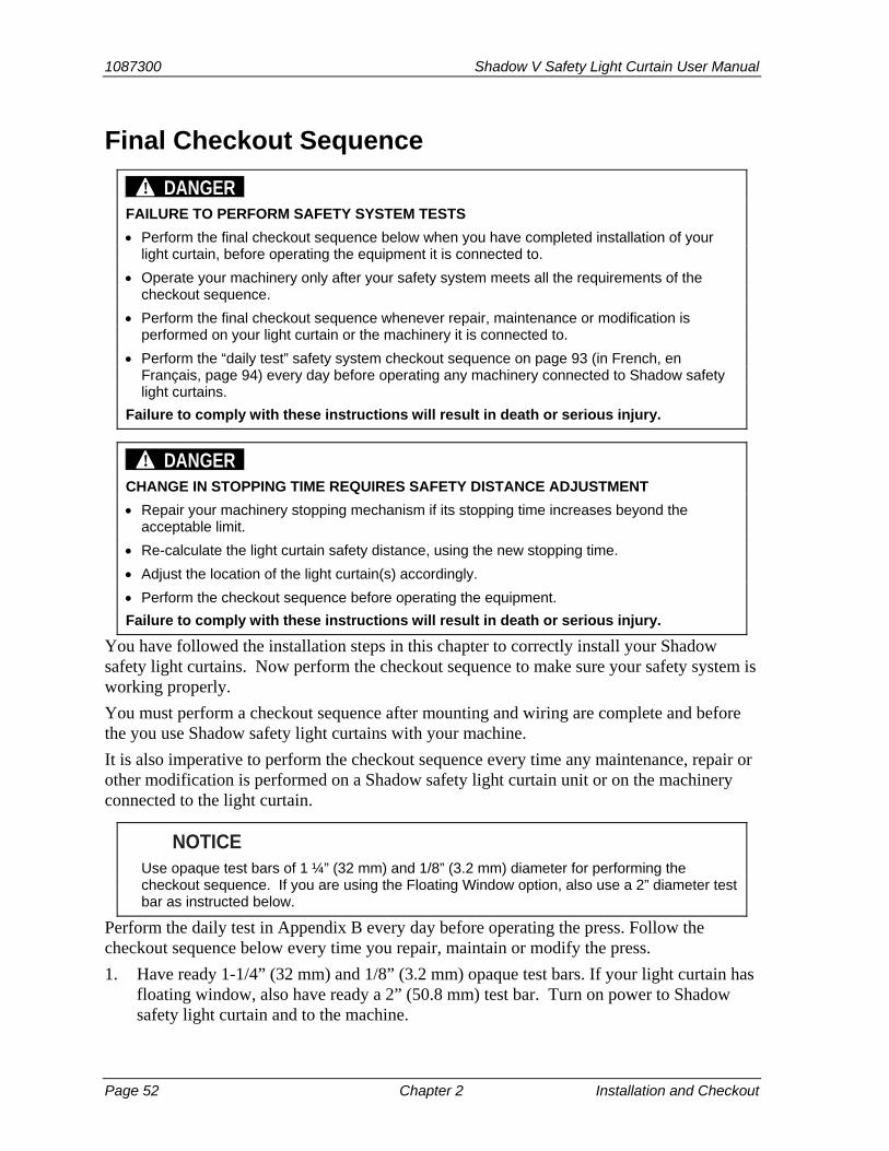
1087300 Shadow V Safety Light Curtain User Manual
Page 52 Chapter 2 Installation and Checkout
Final Checkout Sequence
DANGER! FAILURE TO PERFORM SAFETY SYSTEM TESTS
Perform the final checkout sequence below when you have completed installation of your light curtain, before operating the equipment it is connected to.
Operate your machinery only after your safety system meets all the requirements of the checkout sequence.
Perform the final checkout sequence whenever repair, maintenance or modification is performed on your light curtain or the machinery it is connected to.
Perform the “daily test” safety system checkout sequence on page 93 (in French, en Français, page 94) every day before operating any machinery connected to Shadow safety light curtains.
Failure to comply with these instructions will result in death or serious injury.
DANGER! CHANGE IN STOPPING TIME REQUIRES SAFETY DISTANCE ADJUSTMENT
Repair your machinery stopping mechanism if its stopping time increases beyond the acceptable limit.
Re-calculate the light curtain safety distance, using the new stopping time.
Adjust the location of the light curtain(s) accordingly.
Perform the checkout sequence before operating the equipment.
Failure to comply with these instructions will result in death or serious injury.
You have followed the installation steps in this chapter to correctly install your Shadow safety light curtains. Now perform the checkout sequence to make sure your safety system is working properly.
You must perform a checkout sequence after mounting and wiring are complete and before the you use Shadow safety light curtains with your machine.
It is also imperative to perform the checkout sequence every time any maintenance, repair or other modification is performed on a Shadow safety light curtain unit or on the machinery connected to the light curtain.
NOTICE Use opaque test bars of 1 ¼” (32 mm) and 1/8” (3.2 mm) diameter for performing the
checkout sequence. If you are using the Floating Window option, also use a 2” diameter test bar as instructed below.
Perform the daily test in Appendix B every day before operating the press. Follow the checkout sequence below every time you repair, maintain or modify the press.
1. Have ready 1-1/4” (32 mm) and 1/8” (3.2 mm) opaque test bars. If your light curtain has floating window, also have ready a 2” (50.8 mm) test bar. Turn on power to Shadow safety light curtain and to the machine.

Shadow V Safety Light Curtain User Manual 1087300
Installation and Checkout Chapter 2 page 53
2. Make sure the floating window option has been disabled, if your light curtain has it, by setting the “floating window” switch to the “OFF” position (see Chapter 3).
NOTICE LIGHT CURTAINS EQUIPPED WITH FLOATING WINDOW OPTION
An indicator on the receiver blinks to indicate that floating window has been enabled. This indicator should be off when you perform this checkout procedure with the 1 ¼” test bar. Later you will enable floating window and repeat the test with the 2” bar .
3. Using the 1-1/4” (32 mm) diameter test bar, interrupt the sensing field on the receiver side by passing the bar from the top to the bottom of the receiver’s lens cover. The red light should come on while the bar is in the sensing field.
4. Repeat step 3, passing the 1-1/4” (32 mm) diameter bar from the top to the bottom of the transmitter’s lens cover. The red light should come while the bar is in the sensing field.
5. While the heads are blocked and showing red, verify that the machine will not start while obstructed.
6. Using the 1/8” (3.2 mm) diameter bar, interrupt the sensing field on the receiver side by passing from the top to the bottom of the receiver’s lens cover. The green light should remain on. If the red light comes on, realign the heads to prevent nuisance stops.
7. Repeat step 6, passing the 1/8” diameter bar from the top to the bottom of the transmitter’s lens cover. The green light should remain on. If the red light comes on, realign the heads to prevent nuisance stops.
NOTICE If muting is used, interrupting the light curtain during the non-hazardous portion of the stroke
(upstroke) will not stop the machine. To test, you must interrupt the stroke on the downstroke, which is the hazardous portion of the stroke.
8. Start the machine and interrupt the light field with the 1-1/4” (32 mm) diameter test bar. The red indicator light on the receiver should come on and the machine should stop immediately.
NOTICE Step 9 applies specifically to presses with single cycle and cycle stop capability. If you
cannot single stroke or top stop your press, carry out all steps except Step 9. You must ensure that your Shadow meets the requirements of the other steps before using the Shadow-equipped equipment. Remember, your press must be able to stop when the light beam is broken.
9. Single stroke the machine and make sure it stops at top dead center. Make sure the machine’s braking system is working properly. If the machine does not stop fast enough, adjust the braking system or increase the light curtain’s safety distance.
10. If your light curtains have floating window, enable it and repeat the steps with the 2” (50.8 mm) test bar instead of the 1 ¼” test bar. If you they do not have floating window, go to the next step.
1087300 Shadow V Safety Light Curtain User Manual
Page 54 Chapter 2 Installation and Checkout
11. If your Shadow safety light curtains performed as stated in the checkout sequence, you can now begin to operate your machinery. If you are still experiencing problems, refer to the complete Troubleshooting guides in Chapter 4. For further technical assistance, call Wintriss Tech Support.
If your Shadow safety light curtains did not work exactly as described in this chapter, there is a problem with your mounting or with the Shadow transmitter and receiver. Never to operate the machinery until all conditions of the checkout sequence are met.
See “Chapter 4. Troubleshooting Shadow Safety Light Curtains” to see if you can solve the problem by making some simple checks described in that chapter.
If the safety system still does not work properly, contact Wintriss Tech Support for assistance.
WARNING! UNAUTHORIZED REPAIRS
Perform only the repairs listed in the troubleshooting chapter of this manual. Performing other repairs on the light curtain may affect the performance of the Shadow light curtains and will negate the warranty.
Failure to comply with these instructions could result in death or serious injury.

Shadow V Safety Light Curtain User Manual 1087300 Floating and Blanking Windows Chapter 3 page 55
Chapter 3 – Floating and Blanking Windows
DANGER! INCORRECT SAFETY DISTANCE
Ensure that the correct safety distance exists between the light curtain and the hazardous area. See Chapter 2 for detailed information on object sensitivity, depth penetration factor and calculating the safety distance.
Failure to comply with these instructions will result in death or serious injury.
Blanking windows allow you to disable one or more beams (all but beam #1) of the light curtain in an area where a fixture penetrates the light field. They allow the use of Shadow even though the area scanned by the light field is not clear of all objects.
A floating window allows any one beam of the light curtain to be randomly bypassed. The floating window is useful where stock or an ejected part moves through the light field in a random path.
Instructions for installing and using blanking windows are covered first in this chapter. Floating windows are covered next.

1087300 Shadow V Safety Light Curtain User Manual
page 56 Chapter 3 Floating and Blanking Windows
Blanking Windows Blanking allows stationery fixtures to penetrates into Shadow’s light field. For example, a conveyor or work table, which is required for your operation, protrudes into the light field. A blanking window is installed on the Shadow receiver where the fixture penetrates the field. This disables the light beam that would normally detect the fixture. If the light field is obstructed in any area above or below the fixture or “blanked” light beam, the Shadow will send a stop signal to the press.
The blanking window is easy to install. If you are blanking more than one beam, attach the master blanking window first and then connect “slave” windows on top. This increases the blanked area. Because these blanking windows attach to the receiver, they are clearly visible to personnel— a safety feature.
Blanking Windows Affect Safety Distance
DANGER! INCORRECT SAFETY DISTANCE
Ensure that the correct safety distance exists between the light curtain and the hazardous area. See Chapter 2 for detailed information on object sensitivity, depth penetration factor and calculating the safety distance.
Failure to comply with these instructions will result in death or serious injury.
DANGER! UNPROTECTED ZONE DUE TO EXTRA BLANKING WINDOWS
DO NOT blank more than two beams of the light curtain unless a conveyor or other object completely fills the blanked area, or if you use barrier guards to block any unfilled areas.
Remove blanking windows when they are no longer needed.
Maintain access to blanking master and slave windows under supervisory control to avoid unauthorized usage.
Failure to comply with these instructions will result in death or serious injury.
If you use a blanking window or floating blanking window, safety distance is affected, because the sensitivity of the light curtain is altered. The minimum size that an unblanked Shadow light curtain can sense is an object 11/4” (32 mm) in diameter. This diameter, called the object sensitivity of the light curtain, is the smallest diameter object that the Shadow light curtain will detect anywhere in its field. Anything smaller might fit between two light beams.
You must also consider the depth penetration factor (Dpf ) which is 3.3” (84 mm) for an unblanked Shadow safety light curtain. This factor represents how far an object, such as an operator’s hand, can move through the light path before the light curtain reacts. Depth penetration factor and object sensitivity are interrelated.
A blanking window blocks one light beam, creating an additional ¾” (19 mm) passageway through the light field where no object will be detected. Now the object sensitivity equals 2” (51 mm) wide (11/4”+ ¾”) and the depth penetration factor is 5.9” (150 mm).

Shadow V Safety Light Curtain User Manual 1087300
Floating and Blanking Windows Chapter 3 page 57
Table 3-1. Resolution - R (minimum object sensitivity)
Without
blanking
1 beam
blanking
2 beam
blanking
3 beam
blanking
4 beam
blanking
5-beam
blanking
Resolution * 1.25
(31,8)
2.00
(50,8)
2.75
(69,9)
3.5
(88,9)
4.25
(108.0)
5.00
(127,0)
Beam spacing 0.75
(19,05)
0.75
(19,05)
0.75
(19,05)
0.75
(19,05)
0.75
(19,05)
0.75
(19,05)
Beam diameter 0.50 (12.7)
0.50 (12.7)
0.50 (12.7)
0.50 (12.7)
0.50 (12.7)
0.50 (12.7)
* minimum object sensitivity
The ANSI safety distance formula stipulates that if object sensitivity increases, the safety distance must also be increased. This means that using fixed or floating blanking will require moving the light curtain farther back from the hazardous area.
Adding to Safety Distance for Fixed Blanking
DANGER! INCORRECT SAFETY DISTANCE WHEN USING BLANKING WINDOWS
Ensure that the correct safety distance exists between the light curtain and the hazardous area. See Chapter 2 for detailed information on object sensitivity, depth penetration factor and calculating the safety distance.
When more than one beam is blanked, but the blanked area is not completely obstructed, the depth protection factor is at least 36” (914.4 mm).
Maintain access to blanking master and slave windows under supervisory control to avoid unauthorized usage.
Failure to comply with these instructions will result in death or serious injury.
Use this simple rule of thumb for increasing safety distance. Add 2.6” (66 mm) to the calculated safety distance for every blanking window used. When more than one beam is blanked, but the blanked area is not completely obstructed, the depth protection factor is at least 36” (914.4 mm).
If the blanked area is entirely blocked by a fixture from the transmitter to the receiver such that operator intrusion into this area is impossible, then you do not have to change the safety distance. For instance, you might have a work table that extends into the light field but takes up the whole space between the transmitter and receiver which is unprotected by the light curtain.
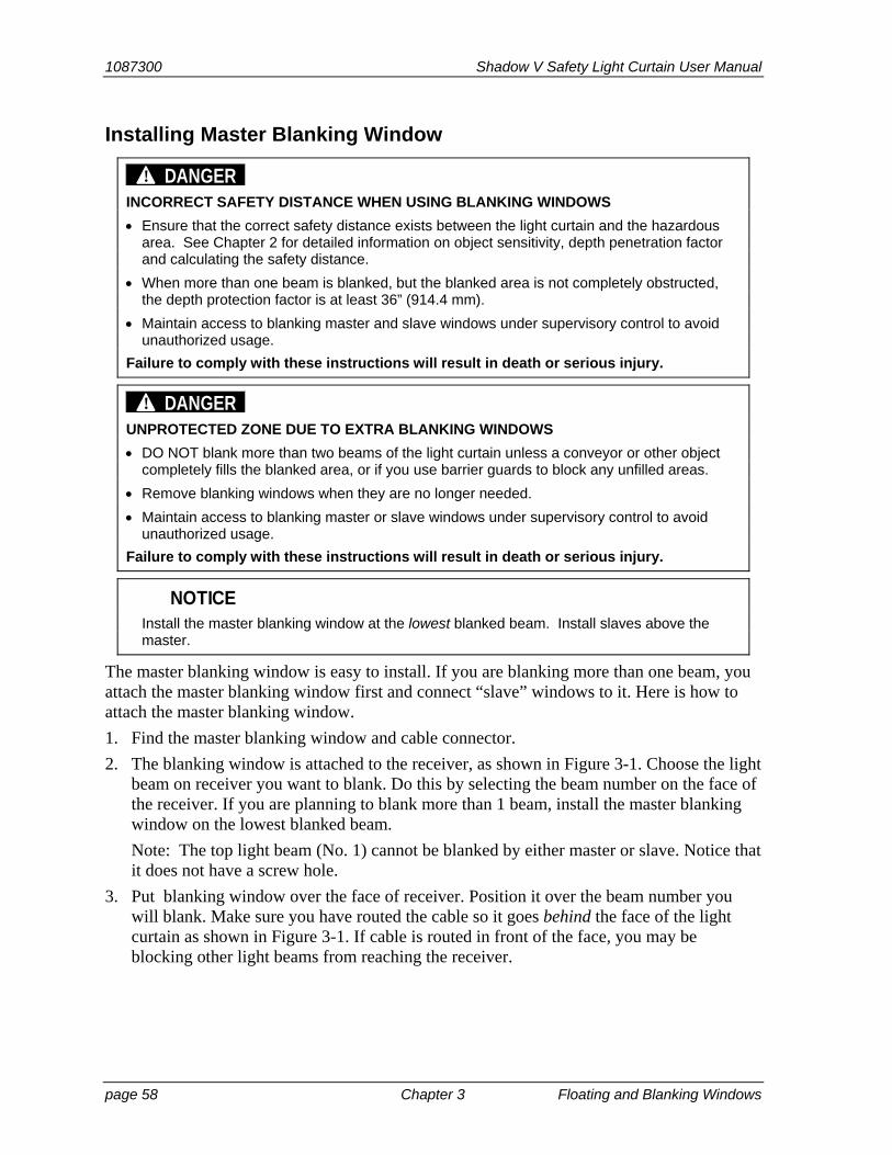
1087300 Shadow V Safety Light Curtain User Manual
page 58 Chapter 3 Floating and Blanking Windows
Installing Master Blanking Window
DANGER! INCORRECT SAFETY DISTANCE WHEN USING BLANKING WINDOWS
Ensure that the correct safety distance exists between the light curtain and the hazardous area. See Chapter 2 for detailed information on object sensitivity, depth penetration factor and calculating the safety distance.
When more than one beam is blanked, but the blanked area is not completely obstructed, the depth protection factor is at least 36” (914.4 mm).
Maintain access to blanking master and slave windows under supervisory control to avoid unauthorized usage.
Failure to comply with these instructions will result in death or serious injury.
DANGER! UNPROTECTED ZONE DUE TO EXTRA BLANKING WINDOWS
DO NOT blank more than two beams of the light curtain unless a conveyor or other object completely fills the blanked area, or if you use barrier guards to block any unfilled areas.
Remove blanking windows when they are no longer needed.
Maintain access to blanking master or slave windows under supervisory control to avoid unauthorized usage.
Failure to comply with these instructions will result in death or serious injury.
NOTICE Install the master blanking window at the lowest blanked beam. Install slaves above the
master.
The master blanking window is easy to install. If you are blanking more than one beam, you attach the master blanking window first and connect “slave” windows to it. Here is how to attach the master blanking window.
1. Find the master blanking window and cable connector.
2. The blanking window is attached to the receiver, as shown in Figure 3-1. Choose the light beam on receiver you want to blank. Do this by selecting the beam number on the face of the receiver. If you are planning to blank more than 1 beam, install the master blanking window on the lowest blanked beam.
Note: The top light beam (No. 1) cannot be blanked by either master or slave. Notice that it does not have a screw hole.
3. Put blanking window over the face of receiver. Position it over the beam number you will blank. Make sure you have routed the cable so it goes behind the face of the light curtain as shown in Figure 3-1. If cable is routed in front of the face, you may be blocking other light beams from reaching the receiver.
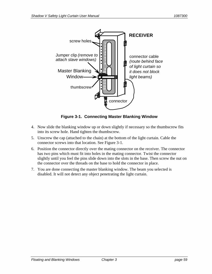
Shadow V Safety Light Curtain User Manual 1087300
Floating and Blanking Windows Chapter 3 page 59
connector
Master BlankingWindow
Jumper clip (remove toattach slave windows)
RECEIVER
connector cable(route behind faceof light curtain soit does not blocklight beams)
thumbscrew
screw holes12345678
910111213141516
Figure 3-1. Connecting Master Blanking Window
4. Now slide the blanking window up or down slightly if necessary so the thumbscrew fits into its screw hole. Hand tighten the thumbscrew.
5. Unscrew the cap (attached to the chain) at the bottom of the light curtain. Cable the connector screws into that location. See Figure 3-1.
6. Position the connector directly over the mating connector on the receiver. The connector has two pins which must fit into holes in the mating connector. Twist the connector slightly until you feel the pins slide down into the slots in the base. Then screw the nut on the connector over the threads on the base to hold the connector in place.
7. You are done connecting the master blanking window. The beam you selected is disabled. It will not detect any object penetrating the light curtain.
1087300 Shadow V Safety Light Curtain User Manual
page 60 Chapter 3 Floating and Blanking Windows
Installing Slave Windows
DANGER! INCORRECT SAFETY DISTANCE WHEN USING BLANKING WINDOWS
Ensure that the correct safety distance exists between the light curtain and the hazardous area. See Chapter 2 for detailed information on object sensitivity, depth penetration factor and calculating the safety distance.
When more than one beam is blanked, but the blanked area is not completely obstructed, the depth protection factor is at least 36” (914.4 mm).
Maintain access to blanking master and slave windows under supervisory control to avoid unauthorized usage.
Failure to comply with these instructions will result in death or serious injury.
DANGER! UNPROTECTED ZONE DUE TO EXTRA BLANKING WINDOWS
DO NOT blank more than two beams of the light curtain unless a conveyor or other object completely fills the blanked area, or if you use barrier guards to block any unfilled areas.
Remove blanking windows when they are no longer needed.
Maintain access to blanking master or slave windows under supervisory control to avoid unauthorized usage.
Failure to comply with these instructions will result in death or serious injury.
You can add slave windows to the master blanking window to blank out more than one beam.
To attach slave windows:
1. Pull the red jumper clip out of its slots on the top of the master blanking window.
2. Plug the slave window into these same slots. You must also plug the jumper into slots on top of the slave window or Shadow will not work. Slave window cannot be used to block beam #1.
3. If you need a larger blanked area, you can add another slave window to the first. Remove the jumper from the first slave window. Connect the slave window, and plug the jumper into slots on the second window.

Shadow V Safety Light Curtain User Manual 1087300
Floating and Blanking Windows Chapter 3 page 61
Floating Window
DANGER! INCORRECT SAFETY DISTANCE WHEN USING FLOATING WINDOW
Ensure that the correct safety distance exists between the light curtain and the hazardous area. See Chapter 2 for detailed information on object sensitivity, depth penetration factor and calculating the safety distance.
Maintain access to blanking windows and floating window under supervisory control to avoid unauthorized usage.
Failure to comply with these instructions will result in death or serious injury.
The floating window provides a means for the random bypass of one beam of the light curtain at a time. It is useful in those applications where material, air ejected parts, or scrap must pass through, or move within the sensing field in a random pattern. In Figure 3-2, for instance, coil stock obstructs different light beams as the coil unwinds. As long as only one beam is obstructed at a time (no matter which one) Shadow allows machinery to operate.
coil stockstraightener
light beams
Figure 3-2. Coil Stock Unwinding Using Floating Window
As with fixed blanking, using the floating blanking window feature affects safety distance because the sensitivity of the light curtain is altered. If you enable the floating window option, add 2.6” (66 mm) to your calculated safety distance. By doing this, you compensate for the increased object sensitivity when floating window is enabled (from 11/4” to 2”).
The floating window may only be used when material or parts will not occupy a space greater than 11/8” within the sensing field. Larger material would cut more than one light beam at a time and cause Shadow to send a stop command.
The floating window is an option built in at the factory. If your Shadow has this feature, you will see a keylock switch on the receiver. A small red indicator light is located under the large indicators on Shadow receivers with floating windows. It blinks when the keylock is in the “on” position and floating window is enabled.
1087300 Shadow V Safety Light Curtain User Manual
page 62 Chapter 3 Floating and Blanking Windows
Adding to Safety Distance for Floating Window
DANGER! INCORRECT SAFETY DISTANCE WHEN USING FLOATING WINDOW
Ensure that the correct safety distance exists between the light curtain and the hazardous area. See Chapter 2 for detailed information on object sensitivity, depth penetration factor and calculating the safety distance. If you purchased Shadows with a floating window, you must add 2.6” (6.6 cm) to the safety distance. This 2.6” (6.6 cm) addition compensates for the increased object sensitivity of Shadows with floating windows (from 1 ¼” to 2”).
Maintain access to blanking windows and floating window under supervisory control to avoid unauthorized usage.
Failure to comply with these instructions will result in death or serious injury.
As with fixed blanking, using the floating blanking window feature affects safety distance because the sensitivity of the light curtain is altered. If you enable the floating window option, add 2.6” (66 mm) to your calculated safety distance. By doing this, you compensate for the increased object sensitivity when floating window is enabled (from 11/4” to 2”).
How to Enable the Floating Window Feature
To use the floating window, just turn the key on the bottom of the receiver to the ON position. The LED indicator on the receiver will blink, indicating that floating window is functioning.
Shadow V Safety Light Curtain User Manual 1087300 Troubleshooting Chapter 4 page 63
Chapter 4 – Troubleshooting
Shadow has complex electronics. You should not attempt to test or repair components on the Shadow circuit boards. This level of troubleshooting and repair must be left to technicians trained in Shadow operation.
However, there are some tests and repairs you can make yourself. In many cases, you will be able to get an inoperative Shadow working again just by changing a blown fuse, replacing indicator lamps, replacing control relays, or re-aligning. How to make these repairs and adjustments is covered in this chapter.
Checks and Repairs You Can Make
DANGER! UNAUTHORIZED REPAIRS
Replace only the control relays, fuses and indicator lamps.
Obtain replacement control relays, fuses and indicator lamps from Wintriss Controls.
DO NOT replace any other components. If you do, this will violate the warranty.
Ensure that repairs are made by qualified personnel. Improper repair by unqualified personnel may put operators at risk of injury.
Failure to comply with these instructions will result in death or serious injury.
There are six checks and repairs you can make yourself if your Shadows stop working or give trouble:
• Checking and Cleaning Windows (page 65)
• Checking and Correcting Shadow Alignment (page 65)
• Checking and Correcting Crosstalk (page 66)
• Checking and Replacing Fuses (page 66)
• Checking and Replacing Indicator Lamps (page 68)
• Checking and Replacing Control Relays (page 69)
The procedures for making these checks and correcting the problem are covered below.
For most of these procedures, you can correct the problem yourself. For instance, if you find the problem is caused by misalignment, a bad control relay, burned out indicator lamps, or a blown fuse, it is easy to make adjustments or replace the bad part.
If you find bad LED outputs in the transmitter, however, or bad phototransistors in the re-ceiver, that unit will have to be factory-repaired. However, once you know which unit is bad, you may be able to substitute another unit for the faulty one until the repairs are made.
If you cannot find the problem by making the checks described above, you will have to send the units back to the factory. Contact Wintriss Tech Support immediately.
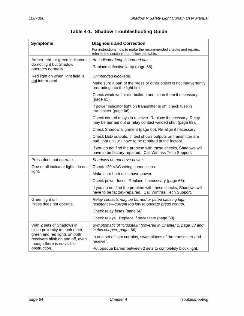
1087300 Shadow V Safety Light Curtain User Manual
page 64 Chapter 4 Troubleshooting
Table 4-1. Shadow Troubleshooting Guide
Symptoms Diagnosis and Correction For instructions how to make the recommended checks and repairs, refer to the sections that follow this table.
Amber, red, or green indicators do not light but Shadow operates normally.
An indicator lamp is burned out.
Replace defective lamp (page 68).
Red light on when light field is not interrupted.
Unintended blockage.
Make sure a part of the press or other object is not inadvertently protruding into the light field.
Check windows for dirt buildup and clean them if necessary (page 65).
If power indicator light on transmitter is off, check fuse in transmitter (page 66).
Check control relays in receiver. Replace if necessary. Relay may be burned out or relay contact welded shut (page 69).
Check Shadow alignment (page 65). Re-align if necessary.
Check LED outputs. If test shows outputs on transmitter are bad, that unit will have to be repaired at the factory.
If you do not find the problem with these checks, Shadows will have to be factory-repaired. Call Wintriss Tech Support.
Press does not operate.
One or all indicator lights do not light.
Shadows do not have power.
Check 120 VAC wiring connections.
Make sure both units have power.
Check power fuses. Replace if necessary (page 66).
If you do not find the problem with these checks, Shadows will have to be factory-repaired. Call Wintriss Tech Support.
Green light on. Press does not operate.
Relay contacts may be burned or pitted causing high resistance—current too low to operate press control.
Check relay fuses (page 66).
Check relays. Replace if necessary (page 69).
With 2 sets of Shadows in close proximity to each other, green and red lights on both receivers blink on and off, even though there is no visible obstruction.
Symptomatic of “crosstalk” (covered in Chapter 2, page 33 and in this chapter, page 66).
In one set of light curtains, swap places of the transmitter and receiver.
Put opaque barrier between 2 sets to completely block light.
Shadow V Safety Light Curtain User Manual 1087300
Troubleshooting Chapter 4 page 65
Checking and Cleaning Windows Sometimes dirt, oil, or another substance can get on the plastic windows of the units, blocking a light beam and preventing press operation. This could be the problem if the red light is on with no objects in the light field.
If your operation is particularly dusty or smoky, general build-up of dirt on the windows could also affect operation.
Both problems are easily corrected by cleaning the windows. The windows on Shadow are the plastic ovals inside the red rectangle.
Clean the windows with a mild solution of detergent and water, a solvent (such as acetone), or an isopropyl-based cleanser. Wipe the window with a clean, particle-free cloth, and avoid excessive rubbing.
Checking and Correcting Shadow Alignment Shadows can go out of alignment if their mounting brackets have been bent, if a unit has been hit (by a die cart, for example), or if mounting bolts have loosened, allowing the units to move slightly. You may have an alignment problem if the red indicator light stays on even when the light field is clear.
To check alignment, first loosen one unit and move it slightly up or down, then rock it in or out to see if you get a green light. See “Aligning and tightening down your Shadows” in Chapter 2 for alignment procedures.
If that does not work, remove either the receiver or transmitter (whichever is easier) from its bracket, and move it right up to the other unit —within 6 to 11 in. (15.2 to 27.9 cm). Arrange a way to supply power to the unit if installed wiring will not reach. Only power wires need be connected if you are moving the receiver. Wiring to press control does not.
Make sure you aim the unit so the windows of each unit are pointing directly at each other in a straight line. (See the alignment information and diagrams in Chapter 2 if you are not sure what this means). Shadows will always align at this close range if working properly.
Alignment problem or bad phototransistor
If the green light comes on at close range, alignment may be the problem. However, you have to make one more check to be sure. Put the units close together again, and adjust them so you get a green light. Now start moving the unit you are holding away from the other, making sure you keep the beams aligned. (The best way to do this is to lay both units on a bench and slide one away from the other. It is not always easy to keep the units aligned while holding one and moving backwards).
If you find the red light comes on at farther distances, but the green light comes on at close range, the problem may be a bad phototransistor or LED. When a phototransistor inside the receiver becomes weak, it can detect a light beam close up, but not at greater distances. LEDs send the light to the phototransistors. If they are weak, they cannot generate enough light at greater distances.

1087300 Shadow V Safety Light Curtain User Manual
page 66 Chapter 4 Troubleshooting
If a bad LED or phototransistor looks like the problem, try the test again to be sure you are not misaligning the units yourself when you move them out. If you get the green light close up but a red light at greater distances, a bad phototransistor or LED is probably the problem. The faulty unit will have to be factory-repaired.
If the green light stays on even as you move the units apart, then your mounting on the press is the problem. A unit may have been hit and moved out of alignment or a bracket may have been bent, sending the unit out of alignment. Check for the cause of misalignment and correct. See Chapter 2 for proper alignment procedures.
If the green light never came on, see the troubleshooting guide to look for other causes of the problem.
Checking and Correcting Crosstalk In some cases, using two sets of Shadow optic heads in close proximity of each other may cause “crosstalk”. Crosstalk occurs when the LEDs from the first set’s transmitter are detected by the phototransistors from the second set’s receiver. Crosstalk could be the problem if the green and red lights on the receivers from set #1 and set #2 flicker back and forth even though there is no visible obstruction causing the light curtains to repeatedly change state.
Diagnose the problem by performing this test. First, try to swap the transmitter with the receiver on one of the sets. If the symptoms go away, crosstalk was the problem. You can also place an opaque barrier of some type (such as a wall or barrier) completely between the two sets. Make sure that the barrier runs all the way from the transmitter to the receiver. If the symptoms go away, crosstalk was the problem.
Refer to the section “Avoiding crosstalk when mounting 2 sets of Shadows” in Chapter 2 which provides alternate ways of mounting 2 sets of light curtains so that you can eliminate the incidence of crosstalk.
Checking and Replacing Fuses
WARNING! ELECTRIC SHOCK HAZARD
Turn off and disconnect power from the Shadow safety light curtain and from the machinery it is connected to before making any wiring connections. This includes disconnecting power to the machine control and motor.
Ensure that all adjustments and repairs are performed by qualified personnel.
Failure to comply with these instructions could result in death or serious injury.
Any time your Shadow units lose power or will not allow press operation, check the fuses first. There are three fuses in the receiver and one fuse on the transmitter. They are easy to check and replace.
The fuses are common 3AG glass cartridge fuses (1/4” dia. x 1 ¼” length) available at any hardware store. Ratings used are ¼ amp and 4 amp. The rating for the fuse is marked next to the fuse on the circuit board.
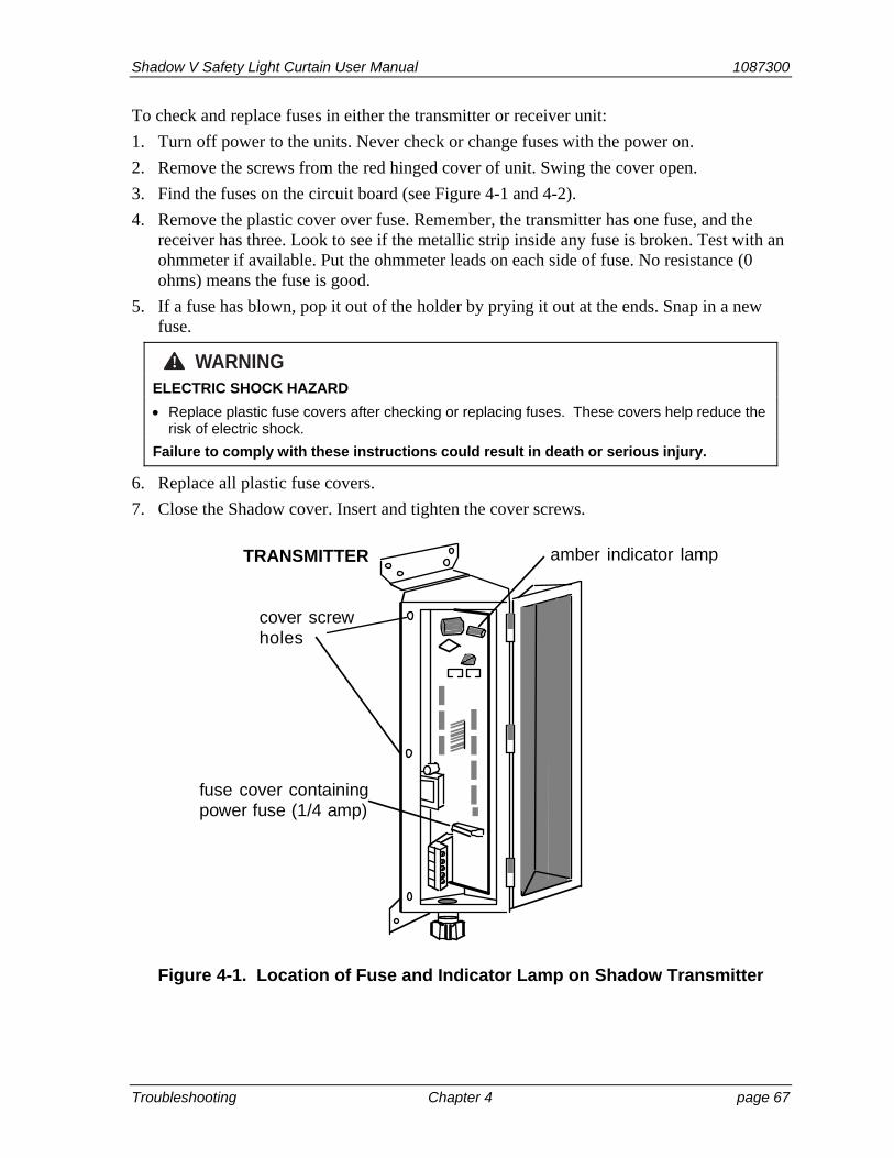
Shadow V Safety Light Curtain User Manual 1087300
Troubleshooting Chapter 4 page 67
To check and replace fuses in either the transmitter or receiver unit:
1. Turn off power to the units. Never check or change fuses with the power on.
2. Remove the screws from the red hinged cover of unit. Swing the cover open.
3. Find the fuses on the circuit board (see Figure 4-1 and 4-2).
4. Remove the plastic cover over fuse. Remember, the transmitter has one fuse, and the receiver has three. Look to see if the metallic strip inside any fuse is broken. Test with an ohmmeter if available. Put the ohmmeter leads on each side of fuse. No resistance (0 ohms) means the fuse is good.
5. If a fuse has blown, pop it out of the holder by prying it out at the ends. Snap in a new fuse.
WARNING! ELECTRIC SHOCK HAZARD
Replace plastic fuse covers after checking or replacing fuses. These covers help reduce the risk of electric shock.
Failure to comply with these instructions could result in death or serious injury.
6. Replace all plastic fuse covers.
7. Close the Shadow cover. Insert and tighten the cover screws.
fuse cover containingpower fuse (1/4 amp)
cover screwholes
TRANSMITTER amber indicator lamp
Figure 4-1. Location of Fuse and Indicator Lamp on Shadow Transmitter
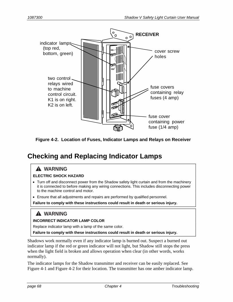
1087300 Shadow V Safety Light Curtain User Manual
page 68 Chapter 4 Troubleshooting
fuse coverscontaining relayfuses (4 amp)
cover screwholes
RECEIVER
indicator lamps
two controlrelays wiredto machinecontrol circuit.K1 is on right.K2 is on left.
(top red,bottom, green)
fuse covercontaining powerfuse (1/4 amp)
Figure 4-2. Location of Fuses, Indicator Lamps and Relays on Receiver
Checking and Replacing Indicator Lamps
WARNING! ELECTRIC SHOCK HAZARD
Turn off and disconnect power from the Shadow safety light curtain and from the machinery it is connected to before making any wiring connections. This includes disconnecting power to the machine control and motor.
Ensure that all adjustments and repairs are performed by qualified personnel.
Failure to comply with these instructions could result in death or serious injury.
WARNING! INCORRECT INDICATOR LAMP COLOR
Replace indicator lamp with a lamp of the same color.
Failure to comply with these instructions could result in death or serious injury.
Shadows work normally even if any indicator lamp is burned out. Suspect a burned out indicator lamp if the red or green indicator will not light, but Shadow still stops the press when the light field is broken and allows operation when clear (in other words, works normally).
The indicator lamps for the Shadow transmitter and receiver can be easily replaced. See Figure 4-1 and Figure 4-2 for their location. The transmitter has one amber indicator lamp.
Shadow V Safety Light Curtain User Manual 1087300
Troubleshooting Chapter 4 page 69
The receiver has two (red and green indicators). Lamps are bayonet-style. They push in and twist out of their sockets just like many automotive-style bulbs for tail lights or turn signals. Lamps can be ordered from Wintriss Controls. To replace an indicator lamp:
1. Turn off power to the Shadow unit with the burned out lamp.
2. Remove the cover screws of the unit. Swing the cover open.
3. Find the lamp on circuit board (see Figure 4-1 and Figure 4-2).
4. Lamps have a bayonet-style connection (like many automotive bulbs). Twist the lamp counterclockwise out of the slots and remove.
5. Push in a new lamp and twist it into the slots. Lamps give off a certain color light. Plastic caps are white. Make sure the new lamp is the correct color. If you mistakenly install a red lamp in place of a green one, for instance, you would get a green light when the light field was obstructed and a red light when it was not. Take precaution to ensure this does not occur.
6. Close the cover and replace the screws.
Checking and Replacing Control Relays
DANGER! IMPROPER SAFETY RELAY REPAIR
Replace both the Shadow’s safety relays before placing the safety product back into operation after the first occurrence of a failed relay.
If a relay fuses
DO NOT reset the Shadow to restart the machine.
Remove the Shadow from operation immediately and replace all of its switching relays before operating the press again.
Failure to comply with these instructions will result in death or serious injury.
WARNING! ELECTRIC SHOCK HAZARD WHEN WORKING INSIDE ENCLOSURE WITH POWER ON
DO NOT touch electrical connections or circuit boards.
Use test equipment only on the terminals specified in the instructions.
Ensure that this test is performed by qualified personnel.
Failure to comply with these instructions could result in death or serious injury.
WARNING! ELECTRIC SHOCK HAZARD WHEN CHANGING RELAYS
Turn off and disconnect power from the Shadow safety light curtain and from the machinery it is connected to before making checking or replacing relays, unless the test requires power to be on (see next warning). This includes disconnecting power to the machine control and motor.
Ensure that all tests and repairs are performed by qualified personnel.
Failure to comply with these instructions could result in death or serious injury.
1087300 Shadow V Safety Light Curtain User Manual
page 70 Chapter 4 Troubleshooting
If the press will not operate even though the Shadow relay contacts are closed and the indicator light is green, check the control relays in the Shadow receiver using a voltmeter. This check will tell you if a relay contact is pitted or burned. When this occurs, resistance at the contact may be so high that no current reaches the press control. If you find a bad relay, replace both the relays. Order new ones from Wintriss Controls.
To check relays with a voltmeter, follow these steps:
1. Turn off power to the Shadow units.
2. Remove the cover screws on the Shadow receiver. Swing the cover open. Locate the relays and wiring connector (see Figure 4–2.)
3. Turn power on.
4. Make sure green light is on. If you no longer see a green light, you will not be able to conduct the following test. See “If Relay Has Failed Completely” at the end of these steps.
5. First test input voltage to relays. Make sure your meter is properly calibrated. The voltmeter should read 120 VAC. Note: Your press control may use 24 VDC voltage or other voltage. If so, check for these voltages.
If the voltage reading differs, the problem is in the control wiring to the Shadow relays.
6. Now test the relay contacts. To test relay K1, place the voltmeter leads across A OUT terminals on connector (see Figure 2-16 in Chapter 2). Voltage should be 0. If not, replace the relay. Check relay K2 by putting the leads across B OUT terminals. If voltage is not 0, replace the relay.
Replace relays
7. To replace the relays, turn power off to the receiver. See Figure 4–2 for the relay location. Relay marked K1 on board controls A OUT slots. Relay marked K2 controls B OUT slots. Slide the plastic ty-wraps off the top of the relays. Then simply pull each relay out of its socket. Hold the new relay over the socket to align the pins, then plug it in. Slide the ty-wrap back over the top of each relay in the same position as before.
Installing the ty-wrap is important. Relays may shake loose if ty-wraps are not in place and tight. If the ty-wrap breaks or becomes loose when removed, install a new one.
8. Close the cover of the receiver and replace the screws.
If Relay Has Failed Completely
If a relay has failed completely (will not energize to close contacts or contacts welded shut), Shadow immediately stops the press and will not allow further press operation. The red light will always be on. In this case, you cannot check relay contacts with a voltmeter. That is
Shadow V Safety Light Curtain User Manual 1087300
Troubleshooting Chapter 4 page 71
because Shadow will not allow any relay operation if a relay failure occurs. Even the contacts of the good relay will be open and all voltages will be zero. Therefore, use a spare. Remove one relay, and plug the spare into its slot. (See Step 7, above, for replacing relays). If the green light does not come on, put the old relay back in. Then remove the other relay, and plug the spare into that slot. If the relay you replaced was bad, then the green light will now come on. Replace both relays as instructed in the previous section.

1087300 Shadow V Safety Light Curtain User Manual
page 72 Chapter 4 Troubleshooting

Shadow V Safety Light Curtain User Manual 1087300 Extracts from OSHA Regulations Appendix A page 73 and ANSI Standards
Appendix A – Extracts from OSHA Regulations and ANSI Standards
WARNING! REFER TO CURRENT REVISIONS OF OSHA/ANSI DOCUMENTS
The following extracts from OSHA and ANSI documents are provided for the user’s convenience only. Refer to the most recent revisions of the original OSHA safety regulations and ANSI standards to ensure that you have the most up-to-date information.
Failure to comply with these instructions could result in death or serious injury.
This appendix provides extracts from the Occupational Safety and Health Administration (OSHA) regulations and the American National Standards Institute (ANSI) standards covering presence-sensing devices.
Extracts from OSHA Regulation 1910.217
WARNING! REFER TO CURRENT REVISIONS OF OSHA/ANSI DOCUMENTS
The following extracts from OSHA and ANSI documents are provided for the user’s convenience only. Refer to the most recent revisions of the original OSHA safety regulations and ANSI standards to ensure that you have the most up-to-date information.
Failure to comply with these instructions could result in death or serious injury.
Reprinted below are extracts from OSHA regulation 1910.217 pertaining to the use of presence-sensing devices for point-of-operation guarding on mechanical power presses. Also reprinted here are interpretations of selected regulations provided by the Precision Metalforming Association (PMA). Extracts from the OSHA regulation are printed in the left-hand column; interpretations by PMA are shown in the right-hand column.
Wintriss makes no claim for the accuracy or effectiveness of the PMA interpretations, and persons making use of this material do so at their own risk. PMA interpretations should not be relied upon for use in any specific application. The material is provided, with PMA’s permission, for informational purposes only.
Refer to the most recent versions of OSHA documents. To obtain copies of OSHA regulations, write to: OSHA’s Office of Information and Consumer Affairs, 200 Constitution Avenue NW, Room N3647, Washington, DC 20210. Tel (202) 219-8151; fax (202) 219-5986.

1087300 Shadow V Safety Light Curtain User Manual
page 74 Appendix A Extracts from OSHA Regulations and ANSI Standards
Extracts from OSHA Regulation 1910.217
OSHA Regulations PMA Interpretation
OSHA 1910.217 (c).
(c) Safeguarding the point of operation.
(1) General requirements.
(i) It shall be the responsibility of the employer to provide and insure the usage of “point of operation guards” or properly applied and adjusted point of operation devices on every operation performed on a mechanical power press. See Table 0-10.
TABLE 0-10
Distance of opening Maximum width of from point of operation opening (inches) hazard (inches)
1/2 to 1 1/2 .................................... 1/4 1 1/2 to 2 1/2 .................................... 3/8 2 1/2 to 3 1/2 .................................... 1/2 3 1/2 to 5 1/2 .................................... 5/8 5 1/2 to 6 1/2 .................................... 3/4 6 1/2 to 7 1/2 .................................... 7/8 7 1/2 to 12 1/2 ................................. 1 1/4 12 1/2 to 15 1/2 ................................. 1 1/2 15 1/2 to 17 1/2 ................................. 1 7/8 17 1/2 to 31 1/2 ................................. 2 1/8
OSHA 1910.217 (c) (3) (i) (a)
(3) Point of operation devices.
(i) Point of operation devices shall protect the operator by:
(a) Preventing and/or stopping normal stroking of the press if the operator’s hands are inadvertently placed in the point of operation.
Presence-sensing device
(c) (3) (i) (a) Refers to the functional requirement of a presence-sensing device which prevents and/or stops normal stroking of the press.
OSHA 1910.217 (c) (3) (iii)
(iii) A presence-sensing point of operation device shall protect the operator as provided in paragraph (c) (3) (i) (a) of this section, and shall be interlocked into the control circuit to prevent or stop slide motion if the operator’s hand or other part of his body is within the sensing field of the device during the downstroke of the press slide.
(a) The device may not be used on machines using full revolution clutches.
(b) The device may not be used as a tripping means to initiate slide motion.
European method (curtain of light) uses self trip safety system effectively. Variance applied for 11/17/73 by Interlake Stamping Company to use this fail safe system.
(c) The device shall be constructed so that a failure within the system does not prevent the normal stopping action from being applied to the press when required, but does prevent the initiation of a successive stroke until the failure is corrected. The failure shall be indicated by the system.
When failure occurs, the best indication is the press won’t run.
Shadow V Safety Light Curtain User Manual 1087300
Extracts from OSHA Regulations Appendix A page 75 and ANSI Standards
Extracts from OSHA Regulation 1910.217
OSHA Regulations PMA Interpretation
(d) Muting (bypassing of the protective function) of such device, during the upstroke of the press slide, is permitted for the purpose of parts ejection, circuit checking and feeding.
Top of stroke is the point at which muting shall cease as it is not possible to set a point on the downstroke as the exact position where the hazard of die closing starts.
(e) The safety distance (Ds) from the sensing field to the point of operation shall be greater than the distance determined by the following formula:
Ds = 63 inches/second x Ts where
Ds = minimum safety distance (inches);
63 inches/second = hand speed constant and Ts = stopping time of the press measured at approximately 90° position of crankshaft rotation (seconds)
Safety distance represents the distance an operator can move his hand during the time it takes a press to stop. The internationally recognized hand reach speed is 63 inches/second.
To determine this safety distance, the stopping time of the press is measured with some appropriate measuring device. The measurement is taken such that the stop signal is given to the press at the 90 degree point of the crank position.
Since some stopping time increase must be accommodated due to braking system deterio-ration, a percentage factor must be added to the measured time to obtain the factor for use in the equation for determining safety distance. A percentage factor of 20% is recommended for presses with new brakes or brakes of good condition. For older brakes, a 10% factor is recommended.
Example: Measured stopping time = 0.190 seconds Time factor = 1.2 x 0.19 = 0.228 seconds Calculation = 63 x 0.228 Safety distance = 14.4 inches
(f) Guards shall be used to protect all areas of entry to the point of operation not protected by the presence-sensing device.
(3) (iii) (f) Great care must be taken to assure that no access to the die area exists unguarded.
OSHA 1910.217 (c) (3) (5)
(5) Additional requirements for safe-guarding. Where the operator feeds or removes parts by placing one or both hands in the point of operation, and a two hand control, presence-sensing device, Type B gate or movable barrier (on a part revolving clutch) is used for safeguarding:
This paragraph tells the condition under which a brake monitoring system is required after November 1, 1975.
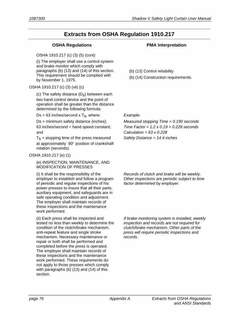
1087300 Shadow V Safety Light Curtain User Manual
page 76 Appendix A Extracts from OSHA Regulations and ANSI Standards
Extracts from OSHA Regulation 1910.217
OSHA Regulations PMA Interpretation
OSHA 1910.217 (c) (3) (5) (cont)
(i) The employer shall use a control system and brake monitor which comply with paragraphs (b) (13) and (14) of this section. This requirement should be complied with by November 1, 1975.
(b) (13) Control reliability
(b) (14) Construction requirements.
OSHA 1910.217 (c) (3) (vii) (c)
(c) The safety distance (Ds) between each two hand control device and the point of operation shall be greater than the distance determined by the following formula:
Ds = 63 inches/second x Ts, where:
Ds = minimum safety distance (inches); 63 inches/second = hand speed constant; and Ts = stopping time of the press measured
at approximately 90 position of crankshaft rotation (seconds).
Example:
Measured stopping Time = 0.190 seconds Time Factor = 1.2 x 0.19 = 0.228 seconds Calculation = 63 x 0.228 Safety Distance = 14.4 inches
OSHA 1910.217 (e) (1)
(e) INSPECTION, MAINTENANCE, AND MODIFICATION OF PRESSES
(i) It shall be the responsibility of the employer to establish and follow a program of periodic and regular inspections of his power presses to insure that all their parts, auxiliary equipment, and safeguards are in safe operating condition and adjustment. The employer shall maintain records of these inspections and the maintenance work performed.
Records of clutch and brake will be weekly. Other inspections are periodic subject to time factor determined by employer.
(ii) Each press shall be inspected and tested no less than weekly to determine the condition of the clutch/brake mechanism, anti-repeat feature and single stroke mechanism. Necessary maintenance or repair or both shall be performed and completed before the press is operated. The employer shall maintain records of these inspections and the maintenance work performed. These requirements do not apply to those presses which comply with paragraphs (b) (13) and (14) of this section.
If brake monitoring system is installed, weekly inspection and records are not required for clutch/brake mechanism. Other parts of the press will require periodic inspections and records.
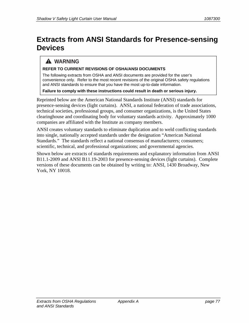
Shadow V Safety Light Curtain User Manual 1087300
Extracts from OSHA Regulations Appendix A page 77 and ANSI Standards
Extracts from ANSI Standards for Presence-sensing Devices
WARNING! REFER TO CURRENT REVISIONS OF OSHA/ANSI DOCUMENTS
The following extracts from OSHA and ANSI documents are provided for the user’s convenience only. Refer to the most recent revisions of the original OSHA safety regulations and ANSI standards to ensure that you have the most up-to-date information.
Failure to comply with these instructions could result in death or serious injury.
Reprinted below are the American National Standards Institute (ANSI) standards for presence-sensing devices (light curtains). ANSI, a national federation of trade associations, technical societies, professional groups, and consumer organizations, is the United States clearinghouse and coordinating body for voluntary standards activity. Approximately 1000 companies are affiliated with the Institute as company members.
ANSI creates voluntary standards to eliminate duplication and to weld conflicting standards into single, nationally accepted standards under the designation “American National Standards.” The standards reflect a national consensus of manufacturers; consumers; scientific, technical, and professional organizations; and governmental agencies.
Shown below are extracts of standards requirements and explanatory information from ANSI B11.1-2009 and ANSI B11.19-2003 for presence-sensing devices (light curtains). Complete versions of these documents can be obtained by writing to: ANSI, 1430 Broadway, New York, NY 10018.
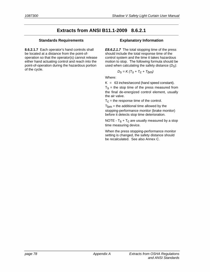
1087300 Shadow V Safety Light Curtain User Manual
page 78 Appendix A Extracts from OSHA Regulations and ANSI Standards
Extracts from ANSI B11.1-2009 8.6.2.1
Standards Requirements Explanatory Information
8.6.2.1.7 Each operator’s hand controls shall be located at a distance from the point-of-operation so that the operator(s) cannot release either hand actuating control and reach into the point-of-operation during the hazardous portion of the cycle.
E8.6.2.1.7 The total stopping time of the press should include the total response time of the control system and the time it takes hazardous motion to stop. The following formula should be used when calculating the safety distance (Ds):
Ds = K (Ts + Tc + Tbm)
Where:
K = 63 inches/second (hand speed constant). Ts = the stop time of the press measured fromthe final de-energized control element, usually the air valve. Tc = the response time of the control.
Tbm = the additional time allowed by the stopping-performance monitor (brake monitor) before it detects stop time deterioration.
NOTE - Ts + Tc are usually measured by a stop time measuring device.
When the press stopping-performance monitor setting is changed, the safety distance should be recalculated. See also Annex C.
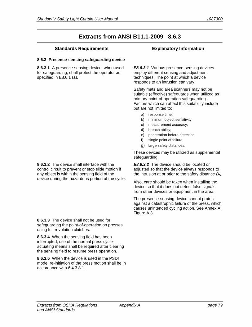
Shadow V Safety Light Curtain User Manual 1087300
Extracts from OSHA Regulations Appendix A page 79 and ANSI Standards
Extracts from ANSI B11.1-2009 8.6.3
Standards Requirements Explanatory Information
8.6.3 Presence-sensing safeguarding device
8.6.3.1 A presence-sensing device, when used for safeguarding, shall protect the operator as specified in E8.6.1 (a).
E8.6.3.1 Various presence-sensing devices employ different sensing and adjustment techniques. The point at which a device responds to an intrusion can vary.
Safety mats and area scanners may not be suitable (effective) safeguards when utilized as primary point-of-operation safeguarding. Factors which can affect this suitability include but are not limited to:
a) response time; b) minimum object sensitivity; c) measurement accuracy; d) breach ability; e) penetration before detection; f) single point of failure;
g) large safety distances.
These devices may be utilized as supplemental safeguarding.
8.6.3.2 The device shall interface with the control circuit to prevent or stop slide motion if any object is within the sensing field of the device during the hazardous portion of the cycle.
E8.6.3.2 The device should be located or adjusted so that the device always responds to the intrusion at or prior to the safety distance Ds.
Also, care should be taken when installing the device so that it does not detect false signals from other devices or equipment in the area.
The presence-sensing device cannot protect against a catastrophic failure of the press, which causes unintended cycling action. See Annex A, Figure A.3.
8.6.3.3 The device shall not be used for safeguarding the point-of-operation on presses using full-revolution clutches.
8.6.3.4 When the sensing field has been interrupted, use of the normal press cycle-actuating means shall be required after clearing the sensing field to resume press operation.
8.6.3.5 When the device is used in the PSDI mode, re-initiation of the press motion shall be in accordance with 6.4.3.8.1.
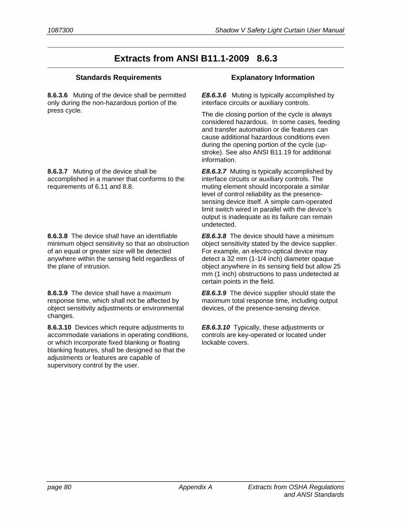
1087300 Shadow V Safety Light Curtain User Manual
page 80 Appendix A Extracts from OSHA Regulations and ANSI Standards
Extracts from ANSI B11.1-2009 8.6.3
Standards Requirements Explanatory Information
8.6.3.6 Muting of the device shall be permitted only during the non-hazardous portion of the press cycle.
E8.6.3.6 Muting is typically accomplished by interface circuits or auxiliary controls.
The die closing portion of the cycle is always considered hazardous. In some cases, feeding and transfer automation or die features can cause additional hazardous conditions even during the opening portion of the cycle (up-stroke). See also ANSI B11.19 for additional information.
8.6.3.7 Muting of the device shall be accomplished in a manner that conforms to the requirements of 6.11 and 8.8.
E8.6.3.7 Muting is typically accomplished by interface circuits or auxiliary controls. The muting element should incorporate a similar level of control reliability as the presence-sensing device itself. A simple cam-operated limit switch wired in parallel with the device’s output is inadequate as its failure can remain undetected.
8.6.3.8 The device shall have an identifiable minimum object sensitivity so that an obstruction of an equal or greater size will be detected anywhere within the sensing field regardless of the plane of intrusion.
E8.6.3.8 The device should have a minimum object sensitivity stated by the device supplier. For example, an electro-optical device may detect a 32 mm (1-1/4 inch) diameter opaque object anywhere in its sensing field but allow 25 mm (1 inch) obstructions to pass undetected at certain points in the field.
8.6.3.9 The device shall have a maximum response time, which shall not be affected by object sensitivity adjustments or environmental changes.
E8.6.3.9 The device supplier should state the maximum total response time, including output devices, of the presence-sensing device.
8.6.3.10 Devices which require adjustments to accommodate variations in operating conditions, or which incorporate fixed blanking or floating blanking features, shall be designed so that the adjustments or features are capable of supervisory control by the user.
E8.6.3.10 Typically, these adjustments or controls are key-operated or located under lockable covers.

Shadow V Safety Light Curtain User Manual 1087300
Extracts from OSHA Regulations Appendix A page 81 and ANSI Standards
Extracts from ANSI B11.1-2009 8.6.3
Standards Requirements Explanatory Information
8.6.3.11 The device shall be provided with a means that visibly indicates when it is functioning properly.
E8.6.3.11 Red and green indicators or other means that can be easily seen by the operator and others should be provided to indicate that the device is functioning.
Indication that the sensing field is being blanked shall be provided. For fixed blanking, the blanked area shall be identified. Supplemental safeguarding shall be provided to prevent access to the hazard through the fixed blanked area.
The blanking function of a presence-sensing safeguarding device desensitizes a portion of the sensing field by disabling one or more channels such that a specific interruption is ignored. Presence-sensing devices can be provided with either fixed or floating blanking. For fixed blanking, the desensitized area does not move or change once configured. Floating blanking allows the blanked area to move within the sensing field.
Means to identify the desensitized area may include but are not limited to:
a) Indicators within the device; b) Signage or marking of the fixed blanked
area;
c) The physical location of the object in the blanked area if movement or removal of the object can be detected and it results in a stop command.
Means of supplemental safeguarding can include completely filling the fixed blanked area to restrict access to the hazard, installing the device at a distance that accounts for the worse case object sensitivity (see 8.6.3.16), or alternate safe-guarding may be provided to prevent access to the hazard.
If means are provided to bypass the device, visible indication that the device is bypassed shall be provided.
Means to provide visible indication may include but are not limited to:
a) colored indicator lights; b) signage; c) physical position; d) awareness barrier (i.e., safety tape);
e) other means.
8.6.3.12 The device shall not fail to respond to the presence of the individual’s hand or other body part due to the presence of a reflective object or workpiece.

1087300 Shadow V Safety Light Curtain User Manual
page 82 Appendix A Extracts from OSHA Regulations and ANSI Standards
Extracts from ANSI B11.1-2009 8.6.3
Standards Requirements Explanatory Information
8.6.3.13 The device shall conform to the requirements of 6.11 and 8.8. In the event of a power failure to the device, the device shall initiate a stop command to the press control system.
8.6.3.14 The interface of the presence-sensing device to the press control shall conform to the requirements of 6.11 and 8.8.
8.6.3.15 The sensitivity of the device to intrusion shall not be adversely affected by changing conditions around the press.
8.6.3.16 The effective sensing field of the device shall be located at distance from the nearest point-of-operation hazard so that individuals cannot reach into the point of operation with a hand or other body part before cessation of motion during the hazardous portion of the cycle.
E8.6.3.16 The total stopping time of the press should include the total response time of the presence-sensing device, as stated by the supplier, the response time of the interface, the response time of the control system, and the time it takes the press to cease slide motion.
The following formula should be used when calculating the safety distance:
Ds = K (Ts + Tc + Tr + Tbm) + Dpf
where
K = 63 inches/second (hand speed constant) Ts = the stop time of the press measured from the final de-energized control element, usually the air valve. Tc = the response time of the press control.
Tr = the response time of the presence-sensing device and its interface, if any, as stated by the supplier or measured by the user. Tbm = the additional stopping time allowed by the stopping-performance monitor before it detects stop time deterioration. Dpf = the added distance due to the penetrationfactor as recommended in ANSI B11.19, AnnexD, Figure D.2. The minimum object sensitivity is stated by the supplier. If beam blankouts or floating window features are used, these figures should be added to the object sensitivity figure before using the chart.

Shadow V Safety Light Curtain User Manual 1087300
Extracts from OSHA Regulations Appendix A page 83 and ANSI Standards
Extracts from ANSI B11.1-2009 8.6.3
Standards Requirements Explanatory Information
8.6.3.16 (cont) NOTE - Ts + Tc is usually measured by a stop time measuring device. See also ANSI B11.19, Annex C and D.
Whenever the press-cycle STOP command or stopping-performance monitor time or angle setting is changed, the safety distance should be recalculated. See also “stopping-performance monitor” (6.12).
NOTE – No increase in safety distance is required for fixed blanking applications if the blanked area is entirely occupied by the material or fixtures.
In some instances, the use of blanking does not allow efficient production of certain piece parts. Horizontal placement of the sensing field, so that it detects the operator’s waist area, may present a solution. In this application, the operator may freely manipulate the workpiece and operate the press as long as the operator stands outside of the horizontal sensing field.
The sensing field should be located so that the operator cannot reach the point-of-operation prior to interrupting the sensing field and completion of the stopping action. Where possible, the sensing field should be of sufficient depth to prevent the operator from standing between the field and the point-of-operation. See also ANSI B11.19, Annex C and D.
8.6.3.17 If the position of the device will allow the operator or others to place themselves between the sensing field and the point-of-operation, additional means shall be provided in conjunction with the device to prevent the operator or others from exposure to the point-of-operation hazard.
E8.6.3.17 Additional means may include manual reset outside of the sensing field of the device or additional barrier guards, safety mats, light curtains or other devices.
Operator controls for each operator located outside of the sensing field of the presence-sensing device may be used.
As an alternative to the reset control and to prevent an individual from stepping behind the sensing field of a PSD, the maximum distance between the light curtain and the machine structure should not exceed 75mm (3 inches). Supplemental safeguarding may be utilized to eliminate a space greater than 75mm.
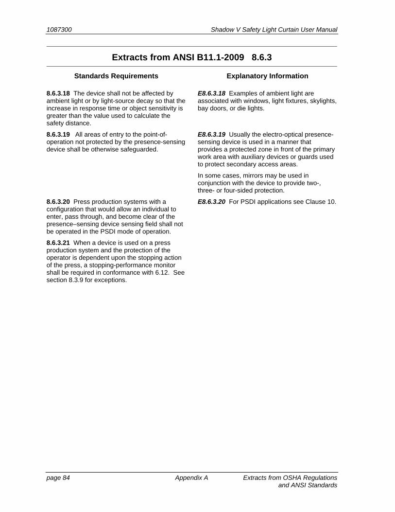
1087300 Shadow V Safety Light Curtain User Manual
page 84 Appendix A Extracts from OSHA Regulations and ANSI Standards
Extracts from ANSI B11.1-2009 8.6.3
Standards Requirements Explanatory Information
8.6.3.18 The device shall not be affected by ambient light or by light-source decay so that the increase in response time or object sensitivity is greater than the value used to calculate the safety distance.
E8.6.3.18 Examples of ambient light are associated with windows, light fixtures, skylights, bay doors, or die lights.
8.6.3.19 All areas of entry to the point-of-operation not protected by the presence-sensing device shall be otherwise safeguarded.
E8.6.3.19 Usually the electro-optical presence-sensing device is used in a manner that provides a protected zone in front of the primary work area with auxiliary devices or guards used to protect secondary access areas.
In some cases, mirrors may be used in conjunction with the device to provide two-, three- or four-sided protection.
8.6.3.20 Press production systems with a configuration that would allow an individual to enter, pass through, and become clear of the presence–sensing device sensing field shall not be operated in the PSDI mode of operation.
E8.6.3.20 For PSDI applications see Clause 10.
8.6.3.21 When a device is used on a press production system and the protection of the operator is dependent upon the stopping action of the press, a stopping-performance monitor shall be required in conformance with 6.12. See section 8.3.9 for exceptions.
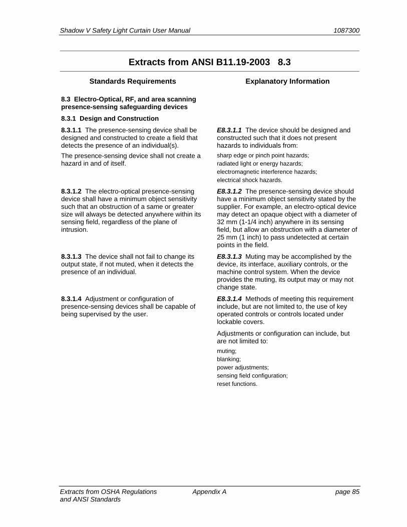
Shadow V Safety Light Curtain User Manual 1087300
Extracts from OSHA Regulations Appendix A page 85 and ANSI Standards
Extracts from ANSI B11.19-2003 8.3
Standards Requirements Explanatory Information
8.3 Electro-Optical, RF, and area scanning presence-sensing safeguarding devices
8.3.1 Design and Construction
8.3.1.1 The presence-sensing device shall be designed and constructed to create a field that detects the presence of an individual(s).
The presence-sensing device shall not create a hazard in and of itself.
E8.3.1.1 The device should be designed and constructed such that it does not present hazards to individuals from:
sharp edge or pinch point hazards; radiated light or energy hazards; electromagnetic interference hazards; electrical shock hazards.
8.3.1.2 The electro-optical presence-sensing device shall have a minimum object sensitivity such that an obstruction of a same or greater size will always be detected anywhere within its sensing field, regardless of the plane of intrusion.
E8.3.1.2 The presence-sensing device should have a minimum object sensitivity stated by the supplier. For example, an electro-optical device may detect an opaque object with a diameter of 32 mm (1-1/4 inch) anywhere in its sensing field, but allow an obstruction with a diameter of 25 mm (1 inch) to pass undetected at certain points in the field.
8.3.1.3 The device shall not fail to change its output state, if not muted, when it detects the presence of an individual.
E8.3.1.3 Muting may be accomplished by the device, its interface, auxiliary controls, or the machine control system. When the device provides the muting, its output may or may not change state.
8.3.1.4 Adjustment or configuration of presence-sensing devices shall be capable of being supervised by the user.
E8.3.1.4 Methods of meeting this requirement include, but are not limited to, the use of key operated controls or controls located under lockable covers.
Adjustments or configuration can include, but are not limited to:
muting; blanking; power adjustments; sensing field configuration; reset functions.
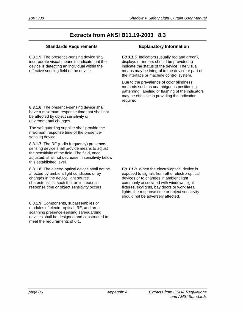
1087300 Shadow V Safety Light Curtain User Manual
page 86 Appendix A Extracts from OSHA Regulations and ANSI Standards
Extracts from ANSI B11.19-2003 8.3
Standards Requirements Explanatory Information
8.3.1.5 The presence-sensing device shall incorporate visual means to indicate that the device is detecting an individual within the effective sensing field of the device.
E8.3.1.5 Indicators (usually red and green), displays or meters should be provided to indicate the status of the device. The visual means may be integral to the device or part of the interface or machine control system.
Due to the prevalence of color blindness, methods such as unambiguous positioning, patterning, labeling or flashing of the indicators may be effective in providing the indication required.
8.3.1.6 The presence-sensing device shall have a maximum response time that shall not be affected by object sensitivity or environmental changes.
The safeguarding supplier shall provide the maximum response time of the presence-sensing device.
8.3.1.7 The RF (radio frequency) presence-sensing device shall provide means to adjust the sensitivity of the field. The field, once adjusted, shall not decrease in sensitivity below this established level.
8.3.1.8 The electro-optical device shall not be affected by ambient light conditions or by changes in the device light source characteristics, such that an increase in response time or object sensitivity occurs.
E8.3.1.8 When the electro-optical device is exposed to signals from other electro-optical devices or to changes in ambient light commonly associated with windows, light fixtures, skylights, bay doors or work area lights, the response time or object sensitivity should not be adversely affected.
8.3.1.9 Components, subassemblies or modules of electro-optical, RF, and area scanning presence-sensing safeguarding devices shall be designed and constructed to meet the requirements of 6.1.
Shadow V Safety Light Curtain User Manual 1087300
Extracts from OSHA Regulations Appendix A page 87 and ANSI Standards
Extracts from ANSI B11.19-2003 8.3
Standards Requirements Explanatory Information
8.3.1.10 The area scanning device shall provide a means or operating mode to verify the size, shape, and detection capabilities of the detection area or zone.
Information shall be provided by the area scanning device supplier to identify the:
a) maximum safeguarding range; b) minimum object sensitivity within the stated safeguarding range; c) maximum field of view in degrees; d) tolerance in the range measurement; and e) detection capabilities with respect to the reflectivity of an object versus the distance to the object.
E8.3.1.10 These devices typically operate on the principle of “diffuse reflectance," which is a principle of transmitting beam(s) of light to form a detection area or zone. When an object enters the detection area, it reflects the transmitted light back to the device, which then evaluates the object's position. The amount of reflected light (degree of reflectance in percent) that can be reliably detected typically ranges from 1.8% to over 90% and can be represented graphically by reflectivity versus distance. For more information, see IEC 61496, parts 1 and 3.
1087300 Shadow V Safety Light Curtain User Manual
page 88 Appendix A Extracts from OSHA Regulations and ANSI Standards
Extracts from ANSI B11.19-2003 8.3
Standards Requirements Explanatory Information
8.3.2 Installation, operation, and maintenance
8.3.2.1 Exposure to the hazard(s) shall not be possible by reaching over, under or around the sensing field of the device. Additional guards or safeguarding devices shall be provided to protect those areas.
E8.3.2.1 The user should select a presence-sensing device adequate to prevent individuals from reaching over, under or around the sensing field during the hazardous portion of the machine cycle. Additional safeguarding may be required in conjunction with the device to meet this requirement.
The effective sensing field shall be of adequate height, width, and depth so that entry of the individual into the hazard area is detected.
If individuals can place themselves between the sensing field and the hazard area, additional safeguarding should be used in conjunction with the device to prevent the individual from exposure to the hazard.
When an individual can pass through the sensing field, see the requirements of 8.3.2.3.
The electro-optical presence-sensing device may fail to detect an individual's presence due to reflective workpieces or objects in the vicinity of the device. Care should be used to ensure that these reflections do not render the device ineffective.
Some examples of reflective objects include, but are not limited to:
machine surfaces; tooling; work pieces; hand tools; auxiliary equipment; workholding tables and fixtures.
Testing each set-up for minimum object sensitivity should be done with an appropriate test rod, following the supplier's recommendation.
Where objects are placed within the defined sensing field of an area optical laser scanner, care should be taken to ensure that:
a) No shadows exist behind the objects such that the device is rendered ineffective; b) Removal of the object will not allow undetected access to a hazard area.
Shadow V Safety Light Curtain User Manual 1087300
Extracts from OSHA Regulations Appendix A page 89 and ANSI Standards
Extracts from ANSI B11.19-2003 8.3
Standards Requirements Explanatory Information
The device shall be installed such that it does not create additional hazards.
Some installation hazards include, but are not limited to:
pinch point hazards created by interference between the device and moving members of the machine; tripping hazards; electrical shock hazards; overhead or other "strike against" hazards; thermal hazards.
Where such conditions can exist, additional safeguarding may be required.
8.3.2.2 The presence-sensing device shall be installed at a location so that the effective sensing field prevents individuals from reaching the hazard(s) during the hazardous portion of the machine cycle.
E8.3.2.2 The safety distance calculation is dependent upon the:
total response time of the device as stated by the safeguarding supplier; response time of the interface; response time of the control system; time it takes the machine to stop hazardous motion; and depth penetration factor of the device.
See Annex D for the formula(e) to calculate the safety distance.
Radio frequency devices have sensing fields that can vary due to:
antenna(e) design; effects of adjacent machinery and equipment; field sensitivity adjustments; and environmental factors (such as humidity or temperature).
Before the machine is used for production purposes, the RF device should be checked to ensure that the effective field protects individuals at the safety distance.

1087300 Shadow V Safety Light Curtain User Manual
page 90 Appendix A Extracts from OSHA Regulations and ANSI Standards
Extracts from ANSI B11.19-2003 8.3
Standards Requirements Explanatory Information
8.3.2.3 The presence-sensing device shall protect individuals from hazards by initiating an immediate stop command to the machine control system when the sensing field of the device is interrupted during the hazardous portion of the machine cycle. It shall require reinitiation of the normal actuating means prior to the start or continuation of motion of the machine.
When an individual can pass through the sensing field of the presence-sensing device, the device shall initiate an immediate stop command to the machine control system and shall require that the device or machine control be manually reset before hazardous motion can occur.
The operator should ensure that no individual is in the safeguarded area before re-setting the device or machine control and initiating hazardous motion.
The reset device shall be located outside of the safeguarded area such that it cannot be reached from within the safeguarded area. Reset of the device or machine control shall not occur until verification that the safeguarded area is clear of individuals.
Key lock reset switches located at various positions around the safeguarded area may be one method of accomplishing this requirement.
8.3.2.4 Components, subassemblies or modules of the interface or machine control system shall meet the requirements of 6.1.
8.3.2.5 Muting of the device shall be permitted during the non-hazardous portion of the machine cycle. Muting of the device shall be accomplished such that a single failure of a component, a subassembly or a module of the system / device that affects the performance of the safety-related functions shall not prevent a normal stop command from being initiated, or shall cause an immediate stop command. In the event of a failure, re-initiation of the machine shall be prevented until the failure is corrected or the system or device is manually reset.
E8.3.2.5 Muting is typically accomplished by interface circuits or auxiliary controls. The muting element should incorporate a similar level of control reliability as the presence-sensing device itself. A simple cam-operated limit switch wired in parallel with the device's output is inadequate, as its failure can remain undetected.
In the presence of a failure, repetitive manual reset of the system or device shall not be used for production.
The intention of a manual reset is to encourage the diagnosis of a failed component, subassembly, device or module. A second failure may occur during the diagnostic or troubleshooting process, negating the safety function(s). Additional safeguarding should be used to protect individuals during this process.
See the definition for control reliability and Annex C for further information.
Shadow V Safety Light Curtain User Manual 1087300
Extracts from OSHA Regulations Appendix A page 91 and ANSI Standards
Extracts from ANSI B11.19-2003 8.3
Standards Requirements Explanatory Information
If the machine has reversing capability where a muting hazard is possible, the control system shall include an automatic means so muting is only permitted in the forward direction.
If an individual can pass through a sensing field when the device is muted, means shall be provided to ensure that the individual is outside of the hazard area, or that the machine ceases hazardous motion when the muting is removed.
One method of meeting this requirement is by the use of a control circuit interlock on the drive motor starter (forward direction contact) to allow "muting" only in the forward direction when the starter is energized. See 8.3.2.1.
8.3.2.6 Bypassing of the device shall be capable of being supervised by the user. Indication that the device is active or bypassed shall be provided and shall be readily observable by individuals protected by the device.
E8.3.2.6 Care should be taken to ensure that the operators and other individuals are aware that the device has been bypassed so that individuals do not assume that the device is active and they are safeguarded when, in fact, the device is bypassed.
When bypassed, the device, interface or control system shall not indicate any state other than "bypass."
An amber indicator lamp or other means may be used to meet this requirement.
When the device is bypassed, other safeguarding must be provided and used.
When bypassed, the device's normal status indicators can be misleading if still active. One method that may be used to meet this requirement is to remove power to the device or to disable the normal status indicators when it is bypassed or not being used.
Due to the prevalence of color blindness, methods such as unambiguous positioning, patterning, labeling or flashing of the indicators may be effective in providing the indication required.
8.3.2.7 The radio frequency device shall not be adversely affected by changes around the machine that may alter the sensitivity of the device such that individuals are no longer detected in the sensing field at the proper safety distance.
E8.3.2.7 The radio frequency device may be affected by changes in the conditions around the machine such as ambient conditions, the placement of parts and tote boxes, grounding conditions of the operator, or the movement of industrial trucks. These changes should not adversely affect the performance of the device.
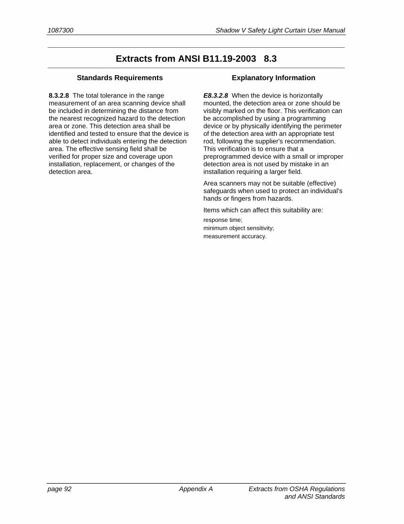
1087300 Shadow V Safety Light Curtain User Manual
page 92 Appendix A Extracts from OSHA Regulations and ANSI Standards
Extracts from ANSI B11.19-2003 8.3
Standards Requirements Explanatory Information
8.3.2.8 The total tolerance in the range measurement of an area scanning device shall be included in determining the distance from the nearest recognized hazard to the detection area or zone. This detection area shall be identified and tested to ensure that the device is able to detect individuals entering the detection area. The effective sensing field shall be verified for proper size and coverage upon installation, replacement, or changes of the detection area.
E8.3.2.8 When the device is horizontally mounted, the detection area or zone should be visibly marked on the floor. This verification can be accomplished by using a programming device or by physically identifying the perimeter of the detection area with an appropriate test rod, following the supplier's recommendation. This verification is to ensure that a preprogrammed device with a small or improper detection area is not used by mistake in an installation requiring a larger field.
Area scanners may not be suitable (effective) safeguards when used to protect an individual's hands or fingers from hazards.
Items which can affect this suitability are:
response time; minimum object sensitivity; measurement accuracy.
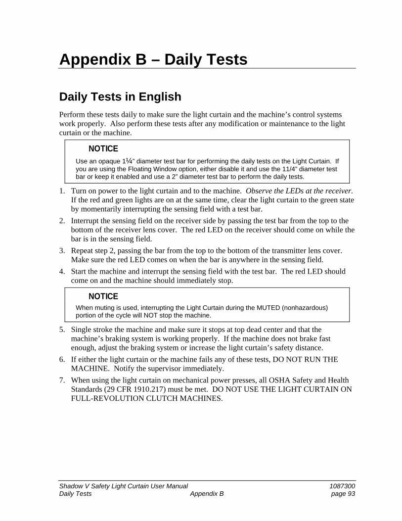
Shadow V Safety Light Curtain User Manual 1087300 Daily Tests Appendix B page 93
Appendix B – Daily Tests
Daily Tests in English Perform these tests daily to make sure the light curtain and the machine’s control systems work properly. Also perform these tests after any modification or maintenance to the light curtain or the machine.
NOTICE
Use an opaque 1¼” diameter test bar for performing the daily tests on the Light Curtain. If you are using the Floating Window option, either disable it and use the 11/4” diameter test bar or keep it enabled and use a 2” diameter test bar to perform the daily tests.
1. Turn on power to the light curtain and to the machine. Observe the LEDs at the receiver. If the red and green lights are on at the same time, clear the light curtain to the green state by momentarily interrupting the sensing field with a test bar.
2. Interrupt the sensing field on the receiver side by passing the test bar from the top to the bottom of the receiver lens cover. The red LED on the receiver should come on while the bar is in the sensing field.
3. Repeat step 2, passing the bar from the top to the bottom of the transmitter lens cover. Make sure the red LED comes on when the bar is anywhere in the sensing field.
4. Start the machine and interrupt the sensing field with the test bar. The red LED should come on and the machine should immediately stop.
NOTICE When muting is used, interrupting the Light Curtain during the MUTED (nonhazardous)
portion of the cycle will NOT stop the machine.
5. Single stroke the machine and make sure it stops at top dead center and that the machine’s braking system is working properly. If the machine does not brake fast enough, adjust the braking system or increase the light curtain’s safety distance.
6. If either the light curtain or the machine fails any of these tests, DO NOT RUN THE MACHINE. Notify the supervisor immediately.
7. When using the light curtain on mechanical power presses, all OSHA Safety and Health Standards (29 CFR 1910.217) must be met. DO NOT USE THE LIGHT CURTAIN ON FULL-REVOLUTION CLUTCH MACHINES.
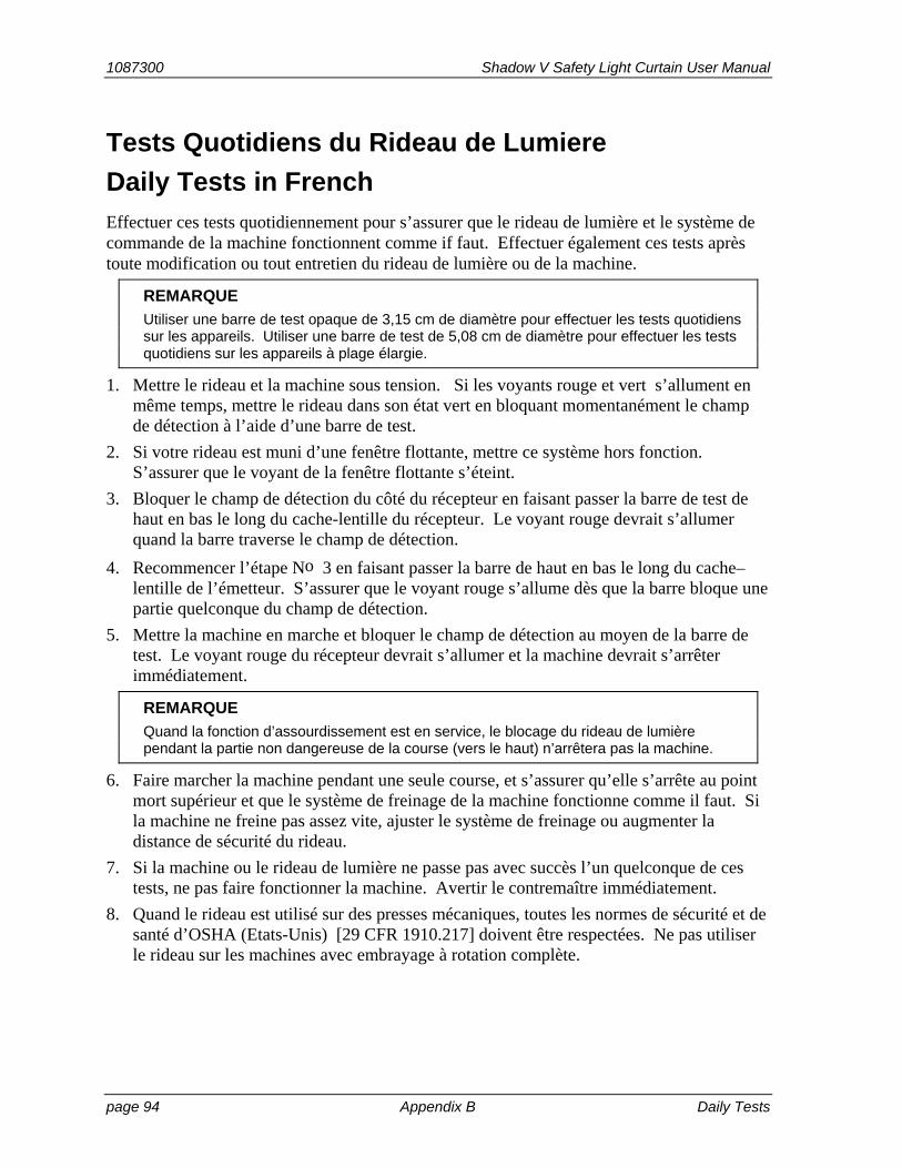
1087300 Shadow V Safety Light Curtain User Manual
page 94 Appendix B Daily Tests
Tests Quotidiens du Rideau de Lumiere
Daily Tests in French
Effectuer ces tests quotidiennement pour s’assurer que le rideau de lumière et le système de commande de la machine fonctionnent comme if faut. Effectuer également ces tests après toute modification ou tout entretien du rideau de lumière ou de la machine.
REMARQUE
Utiliser une barre de test opaque de 3,15 cm de diamètre pour effectuer les tests quotidiens sur les appareils. Utiliser une barre de test de 5,08 cm de diamètre pour effectuer les tests quotidiens sur les appareils à plage élargie.
1. Mettre le rideau et la machine sous tension. Si les voyants rouge et vert s’allument en même temps, mettre le rideau dans son état vert en bloquant momentanément le champ de détection à l’aide d’une barre de test.
2. Si votre rideau est muni d’une fenêtre flottante, mettre ce système hors fonction. S’assurer que le voyant de la fenêtre flottante s’éteint.
3. Bloquer le champ de détection du côté du récepteur en faisant passer la barre de test de haut en bas le long du cache-lentille du récepteur. Le voyant rouge devrait s’allumer quand la barre traverse le champ de détection.
4. Recommencer l’étape No 3 en faisant passer la barre de haut en bas le long du cache–lentille de l’émetteur. S’assurer que le voyant rouge s’allume dès que la barre bloque une partie quelconque du champ de détection.
5. Mettre la machine en marche et bloquer le champ de détection au moyen de la barre de test. Le voyant rouge du récepteur devrait s’allumer et la machine devrait s’arrêter immédiatement.
REMARQUE
Quand la fonction d’assourdissement est en service, le blocage du rideau de lumière pendant la partie non dangereuse de la course (vers le haut) n’arrêtera pas la machine.
6. Faire marcher la machine pendant une seule course, et s’assurer qu’elle s’arrête au point mort supérieur et que le système de freinage de la machine fonctionne comme il faut. Si la machine ne freine pas assez vite, ajuster le système de freinage ou augmenter la distance de sécurité du rideau.
7. Si la machine ou le rideau de lumière ne passe pas avec succès l’un quelconque de ces tests, ne pas faire fonctionner la machine. Avertir le contremaître immédiatement.
8. Quand le rideau est utilisé sur des presses mécaniques, toutes les normes de sécurité et de santé d’OSHA (Etats-Unis) [29 CFR 1910.217] doivent être respectées. Ne pas utiliser le rideau sur les machines avec embrayage à rotation complète.
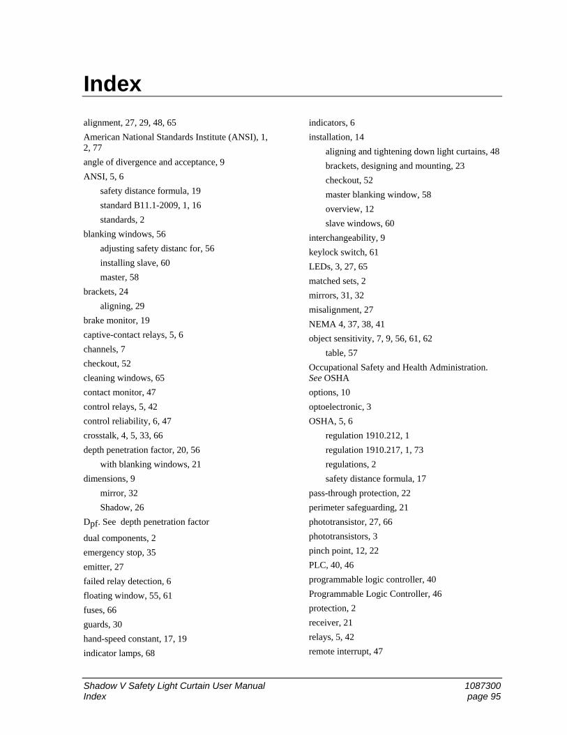
Shadow V Safety Light Curtain User Manual 1087300 Index page 95
Index
alignment, 27, 29, 48, 65
American National Standards Institute (ANSI), 1, 2, 77
angle of divergence and acceptance, 9
ANSI, 5, 6
safety distance formula, 19
standard B11.1-2009, 1, 16
standards, 2
blanking windows, 56
adjusting safety distanc for, 56
installing slave, 60
master, 58
brackets, 24
aligning, 29
brake monitor, 19
captive-contact relays, 5, 6
channels, 7
checkout, 52
cleaning windows, 65
contact monitor, 47
control relays, 5, 42
control reliability, 6, 47
crosstalk, 4, 5, 33, 66
depth penetration factor, 20, 56
with blanking windows, 21
dimensions, 9
mirror, 32
Shadow, 26
Dpf. See depth penetration factor
dual components, 2
emergency stop, 35
emitter, 27
failed relay detection, 6
floating window, 55, 61
fuses, 66
guards, 30
hand-speed constant, 17, 19
indicator lamps, 68
indicators, 6
installation, 14
aligning and tightening down light curtains, 48
brackets, designing and mounting, 23
checkout, 52
master blanking window, 58
overview, 12
slave windows, 60
interchangeability, 9
keylock switch, 61
LEDs, 3, 27, 65
matched sets, 2
mirrors, 31, 32
misalignment, 27
NEMA 4, 37, 38, 41
object sensitivity, 7, 9, 56, 61, 62
table, 57
Occupational Safety and Health Administration. See OSHA
options, 10
optoelectronic, 3
OSHA, 5, 6
regulation 1910.212, 1
regulation 1910.217, 1, 73
regulations, 2
safety distance formula, 17
pass-through protection, 22
perimeter safeguarding, 21
phototransistor, 27, 66
phototransistors, 3
pinch point, 12, 22
PLC, 40, 46
programmable logic controller, 40
Programmable Logic Controller, 46
protection, 2
receiver, 21
relays, 5, 42
remote interrupt, 47
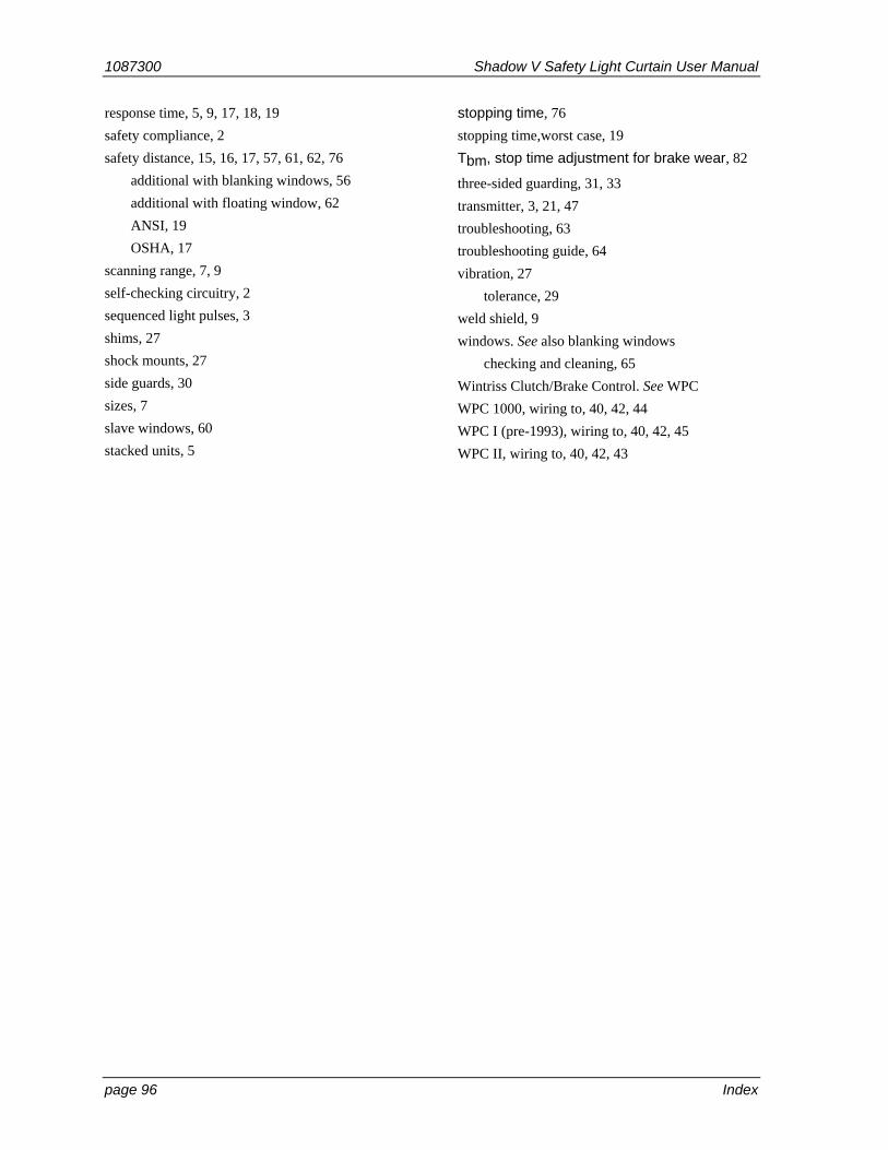
1087300 Shadow V Safety Light Curtain User Manual
page 96 Index
response time, 5, 9, 17, 18, 19
safety compliance, 2
safety distance, 15, 16, 17, 57, 61, 62, 76
additional with blanking windows, 56
additional with floating window, 62
ANSI, 19
OSHA, 17
scanning range, 7, 9
self-checking circuitry, 2
sequenced light pulses, 3
shims, 27
shock mounts, 27
side guards, 30
sizes, 7
slave windows, 60
stacked units, 5
stopping time, 76
stopping time,worst case, 19
Tbm, stop time adjustment for brake wear, 82
three-sided guarding, 31, 33
transmitter, 3, 21, 47
troubleshooting, 63
troubleshooting guide, 64
vibration, 27
tolerance, 29
weld shield, 9
windows. See also blanking windows
checking and cleaning, 65
Wintriss Clutch/Brake Control. See WPC
WPC 1000, wiring to, 40, 42, 44
WPC I (pre-1993), wiring to, 40, 42, 45
WPC II, wiring to, 40, 42, 43
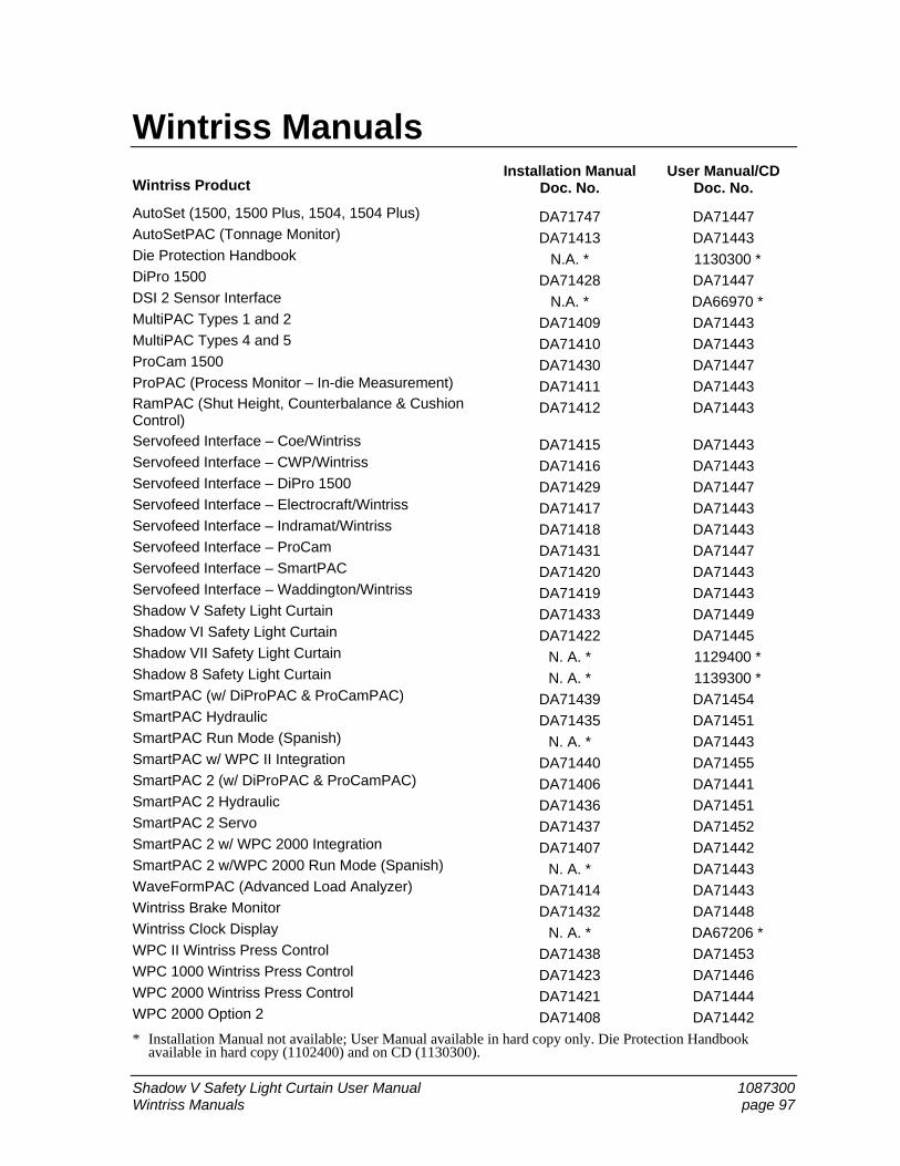
Shadow V Safety Light Curtain User Manual 1087300 Wintriss Manuals page 97
Wintriss Manuals
Wintriss Product Installation Manual
Doc. No.User Manual/CD
Doc. No.
AutoSet (1500, 1500 Plus, 1504, 1504 Plus) DA71747 DA71447AutoSetPAC (Tonnage Monitor) DA71413 DA71443Die Protection Handbook N.A. * 1130300 *DiPro 1500 DA71428 DA71447DSI 2 Sensor Interface N.A. * DA66970 *MultiPAC Types 1 and 2 DA71409 DA71443MultiPAC Types 4 and 5 DA71410 DA71443ProCam 1500 DA71430 DA71447ProPAC (Process Monitor – In-die Measurement) DA71411 DA71443RamPAC (Shut Height, Counterbalance & Cushion Control)
DA71412 DA71443
Servofeed Interface – Coe/Wintriss DA71415 DA71443Servofeed Interface – CWP/Wintriss DA71416 DA71443Servofeed Interface – DiPro 1500 DA71429 DA71447Servofeed Interface – Electrocraft/Wintriss DA71417 DA71443Servofeed Interface – Indramat/Wintriss DA71418 DA71443Servofeed Interface – ProCam DA71431 DA71447Servofeed Interface – SmartPAC DA71420 DA71443Servofeed Interface – Waddington/Wintriss DA71419 DA71443Shadow V Safety Light Curtain DA71433 DA71449Shadow VI Safety Light Curtain DA71422 DA71445Shadow VII Safety Light Curtain N. A. * 1129400 *Shadow 8 Safety Light Curtain N. A. * 1139300 *SmartPAC (w/ DiProPAC & ProCamPAC) DA71439 DA71454SmartPAC Hydraulic DA71435 DA71451SmartPAC Run Mode (Spanish) N. A. * DA71443SmartPAC w/ WPC II Integration DA71440 DA71455SmartPAC 2 (w/ DiProPAC & ProCamPAC) DA71406 DA71441SmartPAC 2 Hydraulic DA71436 DA71451SmartPAC 2 Servo DA71437 DA71452SmartPAC 2 w/ WPC 2000 Integration DA71407 DA71442SmartPAC 2 w/WPC 2000 Run Mode (Spanish) N. A. * DA71443WaveFormPAC (Advanced Load Analyzer) DA71414 DA71443Wintriss Brake Monitor DA71432 DA71448Wintriss Clock Display N. A. * DA67206 *WPC II Wintriss Press Control DA71438 DA71453WPC 1000 Wintriss Press Control DA71423 DA71446WPC 2000 Wintriss Press Control DA71421 DA71444WPC 2000 Option 2 DA71408 DA71442
* Installation Manual not available; User Manual available in hard copy only. Die Protection Handbook available in hard copy (1102400) and on CD (1130300).