security architecture for the internet of things (iot) in ... · piotr polak (philips lighting) ......
TRANSCRIPT
Copyright © Fairhair Alliance 2018
White Paper
Security Architecture for the
Internet of Things (IoT) in Commercial Buildings
March 2018
Piotr Polak (Philips Lighting)
Fairhair Alliance: IoT Security March 2018
2 Copyright © Fairhair Alliance 2018
CONTENTS 1 Introduction ............................................................................................................................................... 3
2 Security overview ...................................................................................................................................... 4
2.1 Requirements .................................................................................................................................... 4
2.2 Solution .............................................................................................................................................. 5
2.3 Timeline ............................................................................................................................................. 6
3 Strong identities ........................................................................................................................................ 6
3.1 Manufacturer identity ....................................................................................................................... 7
3.2 Operational identity .......................................................................................................................... 7
4 Device Enrollment ..................................................................................................................................... 7
4.1 Device enrollment into a security zone ............................................................................................. 8
4.2 Network Access Control .................................................................................................................... 9
4.3 Device operational identity provisioning .......................................................................................... 9
4.4 Manufacturer Usage Description .................................................................................................... 11
5 Security Zones.......................................................................................................................................... 11
6 Authorization ........................................................................................................................................... 12
6.1 Authorization enrollment ................................................................................................................ 12
6.2 Resource request ............................................................................................................................. 13
7 Securing Group Communication ............................................................................................................. 14
7.1 Device group management ............................................................................................................. 14
7.2 Group communication within a single security zone ...................................................................... 15
7.3 Group communication across security zones .................................................................................. 16
8 Conclusion ............................................................................................................................................... 16
9 References ............................................................................................................................................... 17
March 2018 Fairhair Alliance: IoT Security
Copyright © Fairhair Alliance 2018 3
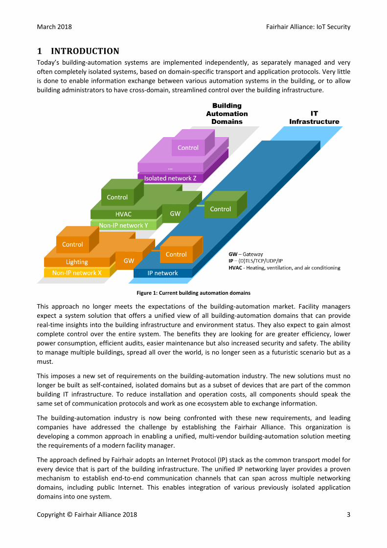
1 INTRODUCTION Today’s building-automation systems are implemented independently, as separately managed and very often completely isolated systems, based on domain-specific transport and application protocols. Very little is done to enable information exchange between various automation systems in the building, or to allow building administrators to have cross-domain, streamlined control over the building infrastructure.
Figure 1: Current building automation domains
This approach no longer meets the expectations of the building-automation market. Facility managers expect a system solution that offers a unified view of all building-automation domains that can provide real-time insights into the building infrastructure and environment status. They also expect to gain almost complete control over the entire system. The benefits they are looking for are greater efficiency, lower power consumption, efficient audits, easier maintenance but also increased security and safety. The ability to manage multiple buildings, spread all over the world, is no longer seen as a futuristic scenario but as a must.
This imposes a new set of requirements on the building-automation industry. The new solutions must no longer be built as self-contained, isolated domains but as a subset of devices that are part of the common building IT infrastructure. To reduce installation and operation costs, all components should speak the same set of communication protocols and work as one ecosystem able to exchange information.
The building-automation industry is now being confronted with these new requirements, and leading companies have addressed the challenge by establishing the Fairhair Alliance. This organization is developing a common approach in enabling a unified, multi-vendor building-automation solution meeting the requirements of a modern facility manager.
The approach defined by Fairhair adopts an Internet Protocol (IP) stack as the common transport model for every device that is part of the building infrastructure. The unified IP networking layer provides a proven mechanism to establish end-to-end communication channels that can span across multiple networking domains, including public Internet. This enables integration of various previously isolated application domains into one system.
Fairhair Alliance: IoT Security March 2018
4 Copyright © Fairhair Alliance 2018
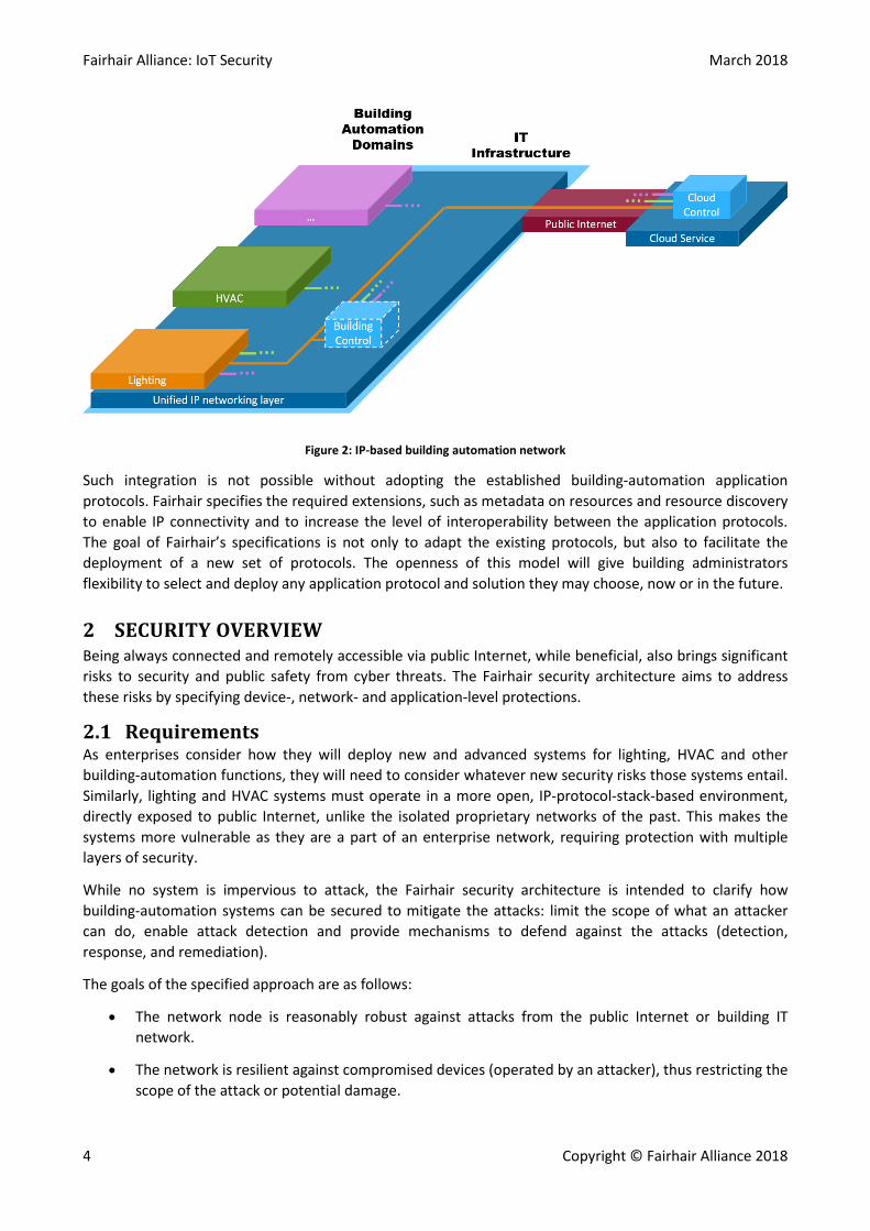
Figure 2: IP-based building automation network
Such integration is not possible without adopting the established building-automation application protocols. Fairhair specifies the required extensions, such as metadata on resources and resource discovery to enable IP connectivity and to increase the level of interoperability between the application protocols. The goal of Fairhair’s specifications is not only to adapt the existing protocols, but also to facilitate the deployment of a new set of protocols. The openness of this model will give building administrators flexibility to select and deploy any application protocol and solution they may choose, now or in the future.
2 SECURITY OVERVIEW Being always connected and remotely accessible via public Internet, while beneficial, also brings significant risks to security and public safety from cyber threats. The Fairhair security architecture aims to address these risks by specifying device-, network- and application-level protections.
2.1 Requirements As enterprises consider how they will deploy new and advanced systems for lighting, HVAC and other building-automation functions, they will need to consider whatever new security risks those systems entail. Similarly, lighting and HVAC systems must operate in a more open, IP-protocol-stack-based environment, directly exposed to public Internet, unlike the isolated proprietary networks of the past. This makes the systems more vulnerable as they are a part of an enterprise network, requiring protection with multiple layers of security.
While no system is impervious to attack, the Fairhair security architecture is intended to clarify how building-automation systems can be secured to mitigate the attacks: limit the scope of what an attacker can do, enable attack detection and provide mechanisms to defend against the attacks (detection, response, and remediation).
The goals of the specified approach are as follows:
• The network node is reasonably robust against attacks from the public Internet or building IT network.
• The network is resilient against compromised devices (operated by an attacker), thus restricting the scope of the attack or potential damage.
March 2018 Fairhair Alliance: IoT Security
Copyright © Fairhair Alliance 2018 5
• The system will provide economical, automated, and yet reasonably secure, installation and reconfiguration capabilities, such that a new device need only be pulled out of a box by an installer and plugged in for it to find any relevant controllers, perform any relevant discovery, and then operate.
• Provide a security architecture that
• is open and compliant with existing and new specifications of the main standardization body for Internet, the Internet Engineering Task Force (IETF), and
• supports system designers to meet existing and emerging regulations and security standards, such as IEC 62443 [1] or ANSI UL 2900 [2].
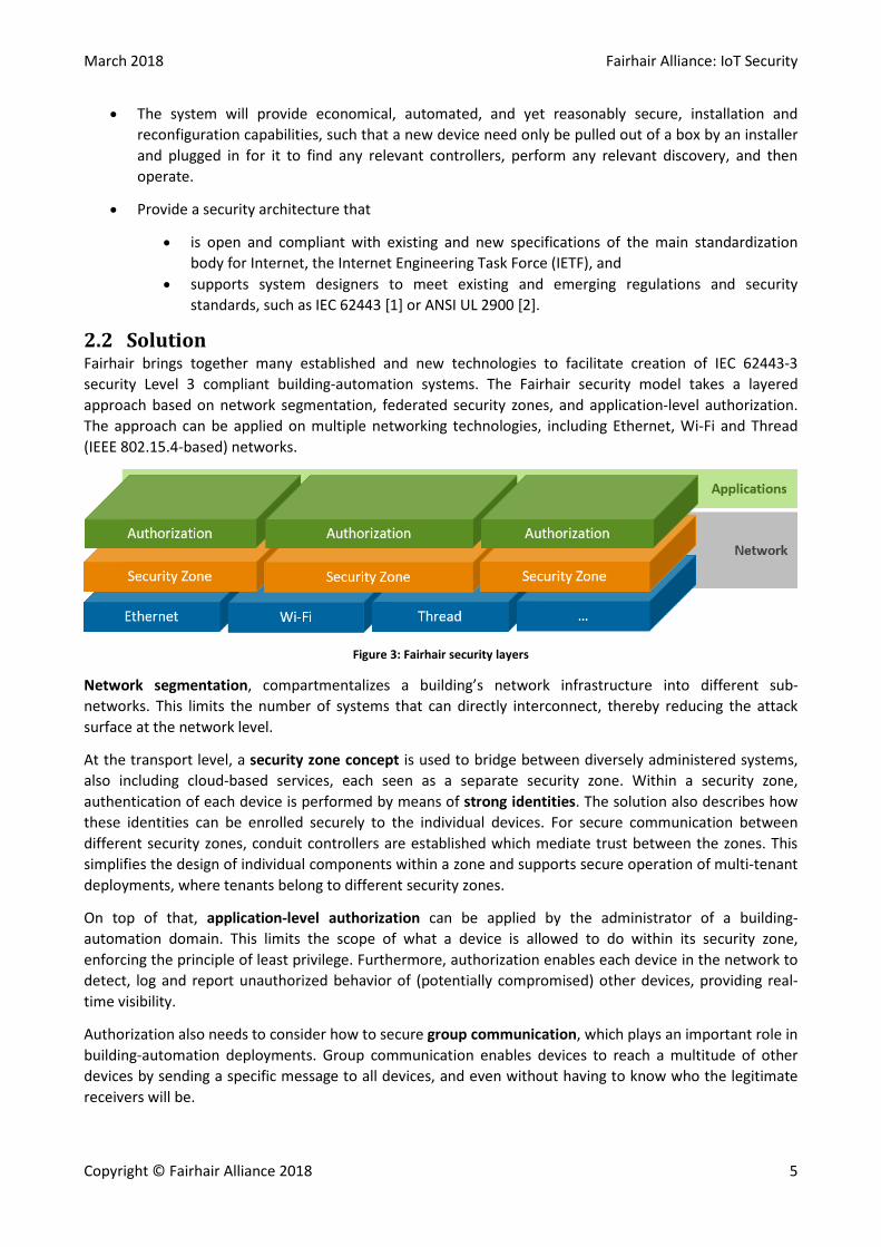
2.2 Solution Fairhair brings together many established and new technologies to facilitate creation of IEC 62443-3 security Level 3 compliant building-automation systems. The Fairhair security model takes a layered approach based on network segmentation, federated security zones, and application-level authorization. The approach can be applied on multiple networking technologies, including Ethernet, Wi-Fi and Thread (IEEE 802.15.4-based) networks.
Figure 3: Fairhair security layers
Network segmentation, compartmentalizes a building’s network infrastructure into different sub-networks. This limits the number of systems that can directly interconnect, thereby reducing the attack surface at the network level.
At the transport level, a security zone concept is used to bridge between diversely administered systems, also including cloud-based services, each seen as a separate security zone. Within a security zone, authentication of each device is performed by means of strong identities. The solution also describes how these identities can be enrolled securely to the individual devices. For secure communication between different security zones, conduit controllers are established which mediate trust between the zones. This simplifies the design of individual components within a zone and supports secure operation of multi-tenant deployments, where tenants belong to different security zones.
On top of that, application-level authorization can be applied by the administrator of a building-automation domain. This limits the scope of what a device is allowed to do within its security zone, enforcing the principle of least privilege. Furthermore, authorization enables each device in the network to detect, log and report unauthorized behavior of (potentially compromised) other devices, providing real-time visibility.
Authorization also needs to consider how to secure group communication, which plays an important role in building-automation deployments. Group communication enables devices to reach a multitude of other devices by sending a specific message to all devices, and even without having to know who the legitimate receivers will be.
Fairhair Alliance: IoT Security March 2018
6 Copyright © Fairhair Alliance 2018
The Fairhair security architecture enables enterprises to address special requirements of professional building-automation applications typically handled by multiple operators addressing different application domains like lighting, safety or HVAC. The approach provides an elegant, simple and open-standard-based solution that makes it possible to:
• Establish multiple security zones. • Facilitate secure interactions between devices in one security zone, and in between devices that
are part of different security zones.
The solution can be deployed on top of any IP network deployment and provides a uniform communication infrastructure independent from the underlying networking technologies.
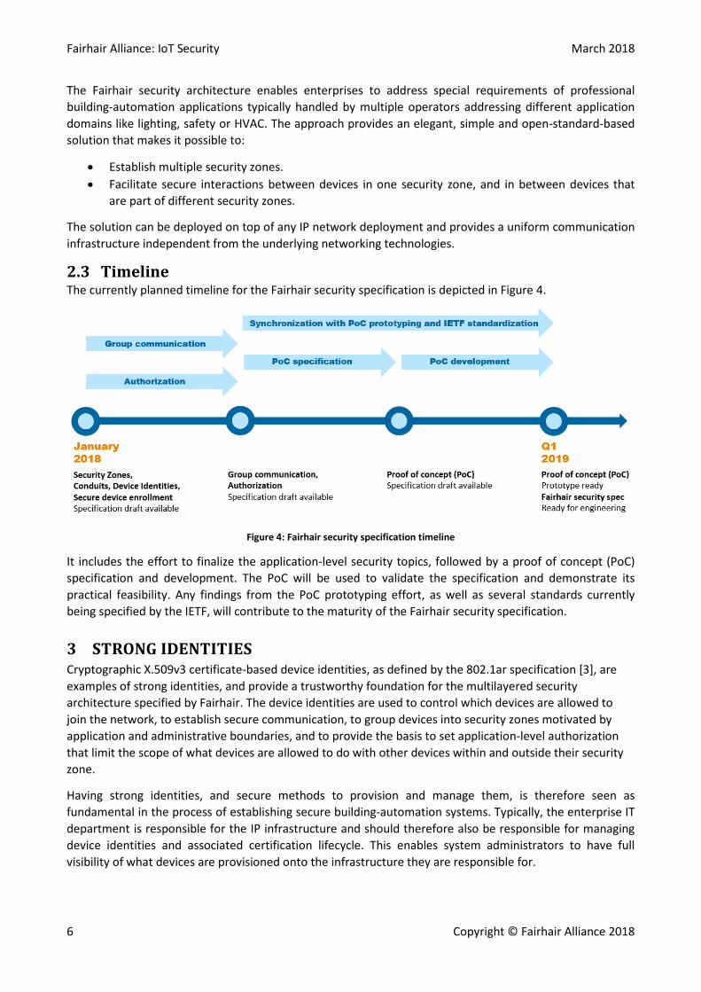
2.3 Timeline The currently planned timeline for the Fairhair security specification is depicted in Figure 4.
Figure 4: Fairhair security specification timeline
It includes the effort to finalize the application-level security topics, followed by a proof of concept (PoC) specification and development. The PoC will be used to validate the specification and demonstrate its practical feasibility. Any findings from the PoC prototyping effort, as well as several standards currently being specified by the IETF, will contribute to the maturity of the Fairhair security specification.
3 STRONG IDENTITIES Cryptographic X.509v3 certificate-based device identities, as defined by the 802.1ar specification [3], are examples of strong identities, and provide a trustworthy foundation for the multilayered security architecture specified by Fairhair. The device identities are used to control which devices are allowed to join the network, to establish secure communication, to group devices into security zones motivated by application and administrative boundaries, and to provide the basis to set application-level authorization that limit the scope of what devices are allowed to do with other devices within and outside their security zone.
Having strong identities, and secure methods to provision and manage them, is therefore seen as fundamental in the process of establishing secure building-automation systems. Typically, the enterprise IT department is responsible for the IP infrastructure and should therefore also be responsible for managing device identities and associated certification lifecycle. This enables system administrators to have full visibility of what devices are provisioned onto the infrastructure they are responsible for.

March 2018 Fairhair Alliance: IoT Security
Copyright © Fairhair Alliance 2018 7
Figure 5: Device identities
The Fairhair security architecture relies on two types of device identities as depicted in Figure 5:
• Manufacturer device identity to identify the device at installation time, • Operational device identity to identify the device after secure installation.
Every Fairhair-compliant device must possess a unique manufacturer device identity. This identity is used during the device enrollment process to provision the device’s operational identity.
Both identities should be protected at device level, so they cannot be easily extracted and cloned by an attacker. This type of protection is already available in many of today’s embedded devices of platforms.
3.1 Manufacturer identity The device manufacturer identity is a static (not changed over a device lifetime) identity that is generated by the device manufacturer and provisioned onto devices during manufacturing. The identity enables the manufacturer to identify the device and keep track of the device history over its lifetime: when it was produced, when and by what enterprise it was provisioned or if it was compromised (e.g. cloned). This identity can also be used by the manufacturer to establish end-to-end secure communication with a device, and to enable secure in-the-field firmware updates.
Most importantly, this identity is used in the device enrollment process as described below.
3.2 Operational identity The device operational identity is a configurable identity that may need to be renewed over a device lifetime. It is issued by the administrator of the network (typically the IT department controlling the IP infrastructure) and provisioned during the enrollment process described below. The identity is used to establish secure communication between devices, to enforce security zones and to assign application-level authorization for the device.
4 DEVICE ENROLLMENT Building-automation domains, established using device operational identities, will no longer be isolated islands but will be part of the common, IP-based networking building infrastructure. Because of this, the IT department needs to be involved in the process of purchasing the devices and the building network establishment. IT involvement is necessary to not only gain control over what devices are enrolled into the common infrastructure but also to issue the operational identities and control the enrollment process.
Fairhair Alliance: IoT Security March 2018
8 Copyright © Fairhair Alliance 2018
Figure 6: Device enrollment steps
The device enrollment process described by the Fairhair security specification provides the means for the manufacturer to introduce the device into the IT infrastructure. This is done to automate and secure the process of device enrollment, allowing seamless, remote provisioning of the operational identities and authorization tokens, [4].
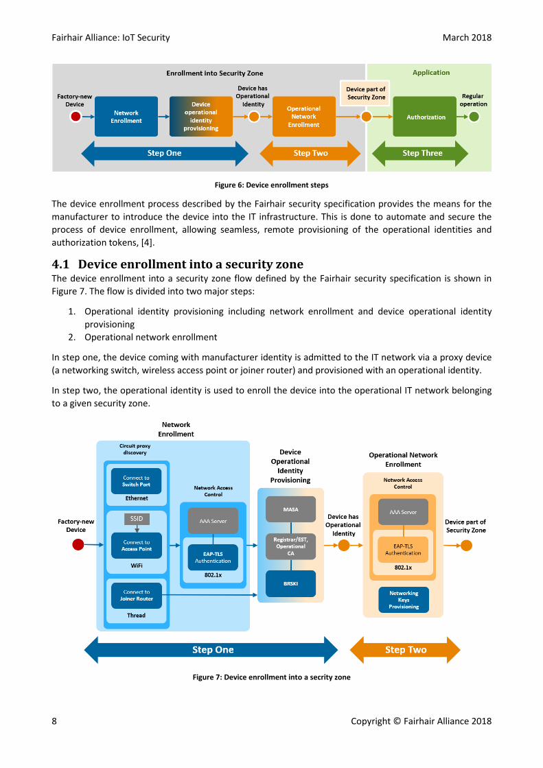
4.1 Device enrollment into a security zone The device enrollment into a security zone flow defined by the Fairhair security specification is shown in Figure 7. The flow is divided into two major steps:
1. Operational identity provisioning including network enrollment and device operational identity provisioning
2. Operational network enrollment
In step one, the device coming with manufacturer identity is admitted to the IT network via a proxy device (a networking switch, wireless access point or joiner router) and provisioned with an operational identity.
In step two, the operational identity is used to enroll the device into the operational IT network belonging to a given security zone.
Figure 7: Device enrollment into a secrity zone

March 2018 Fairhair Alliance: IoT Security
Copyright © Fairhair Alliance 2018 9
As the result of the enrollment process the device becomes fully operational. The device has access to the operational network and is assigned to the required security zone by receiving the right operational identity, issued by the administrator of the zone.
4.2 Network Access Control The Network Access Control (NAC) gives the IT administrator control over what devices can join the network. The NAC is used in the first step of the device enrollment flow to enroll the device into the network providing access to Bootstrapping Remote Secure Key Infrastructure (BRSKI), [5].
Once the device is successfully connected to the network and provisioned with the operational identity (using BRSKI described in the following sections), another NAC operation is performed in step two of the enrollment flow to enroll the device into the operational network as depicted in Figure 7.
There are various mechanisms that can be deployed while implementing NAC, depending on which connectivity technology is used by a device. The following figure shows, as an example, the options available for the Ethernet devices. These include:
1. Port/MAC based – statically assigned rules using a switch configuration 2. MAC authentication bypass - using an AAA server 3. Certificate based - using an AAA server
Figure 8: Network Access Control options for Ethernet devices
The result of all these options is the same: if successful, the device is allowed to access the IT network. What may vary is the level of security, visibility and control the administrator gets in the process. While all the listed options can be deployed in step one of the enrollment flow, it is recommended to use option 3 utilizing the manufacturer certificate-based device identity.
It must be noted that NAC is not always required. For instance, for a device using Thread connectivity the secure connection to BRSKI is facilitated by the Thread Joiner Router as depicted in Figure 7.
4.3 Device operational identity provisioning The autonomous enrollment specified by Fairhair adopts the BRSKI process as defined by IETF [5].
The process involves four main steps, as depicted in Figure 9:

Fairhair Alliance: IoT Security March 2018
10 Copyright © Fairhair Alliance 2018
1. The device is authenticated based on a strong identity, the device manufacturer certificate, provisioned by the manufacturer, and a secure channel is established from the device to the Registrar server controlled by the network administrator.
2. The device sends (via the Registrar) a request (voucher) to the Manufacturer Authorized Signing Authority (MASA) cloud service. Upon receiving it, the MASA service shares the device log with the Registrar and sends back a signed message including the Registrar CA root certificate to the device.
3. The device extracts the root certificate and verifies the Registrar identity. At this point both the device and the Registrar are mutually authenticated.
4. The operational identity (operational certificate) is provisioned onto the device using standardized EST protocol as defined by IETF [6], [7].
The trust relation between the device manufacturer operating the Manufacturer Authorized Signing Authority (MASA) service and the network operator owning the Registrar is the key feature enabling this process. Being accepted by the Registrar is equivalent to being accepted into the network.
In the process, the MASA service facilitates establishment of mutual trust between the new device and the Registrar, enabling operational identity provisioning. As the result, the new device establishes trust towards all devices participating in the security zone.
Figure 9: BRSKI identity provisioning process
The process described here can be fully automated when network infrastructure allows direct connectivity to the domain Registrar and the device MASA service as defined in [5]. However, it is also possible to utilize out-of-band communication and provision the new device manually if required.
Once the device operational identity is set, the authorization provisioning can be performed. The authorization tokens defining the scope of interaction with other devices are provisioned into the device, using the authorization server as described in Authorization section below.

March 2018 Fairhair Alliance: IoT Security
Copyright © Fairhair Alliance 2018 11
4.4 Manufacturer Usage Description During the enrollment process, a device can provide a pointer to the manufacturer usage description (MUD) that defines what sort of network level access a device needs, such that basic access controls can be deployed, see [8]. In this way the network infrastructure can be automatically configured to reject, log and report unwanted communications to or from the device.
This network-level mechanism complements the application-level authorization, also enabling malicious behavior detection at the application layer.
The following figure shows one of the possible configurations how MUD components can be implemented.
Figure 10: MUD Architecture
In the depicted configuration, the AAA Server involved in NAC also interacts with the MUD Controller and is responsible for configuring the switch, according to the information provided by the controller.
5 SECURITY ZONES The security zones may span multiple network segments and are established by grouping devices based on function, location and responsible organization. All devices belonging to a security zone are provisioned with a corresponding operational identity which:
• Identifies them as member of that security zone, and • Enables them to establish authenticated and secure communication channels to other devices in
the same security zone.
Figure 11: Security zones
If data exchange between security zones (or outside of the overall building automation domain, such as to external cloud service) is required, a security zone may incorporate controller (CTRL) devices that are responsible for communicating with other security zones, or the cloud service over secure channels called conduits, as depicted in Figure 11.

Fairhair Alliance: IoT Security March 2018
12 Copyright © Fairhair Alliance 2018
By means of a conduit, two operational organizations may easily set up a secure communication channel between their security zones, while also defining and controlling the scope of communications using authorization.
The conduits are established by authorizing the pair of controllers belonging to two different security zones, to communicate with each other. The conduits are established during the device enrollment process by issuing operational identities for the two controllers linked by the conduit. Each of the controllers is provisioned with two operational identities originating from both security zones linked by the conduit. On top of that, application-level authorization can further limit the scope of what type of requests can be exchanged between the controllers.
The conduit controller is responsible for “policing” the data exchanged between zones, acting on behalf of devices belonging to the security zone from which the controller originates.
The conduit controller can also provide application-level protocol translation to bridge different application protocols.
6 AUTHORIZATION The operational identities issued to all devices belonging to a single security zone are used to establish secure (Datagram) Transport Layer Security (DTLS/TLS) channels between the devices and between devices and related services of that security zone. That means only devices participating in a zone can communicate with each other and contact the related services. Any connection request coming from outside the zone, from a device not having a valid operational identity issued by the administrator of the zone, is rejected and logged.
However, the risk that, at some point in time, a device participating in the security zone is compromised can never be ignored. In such a case, a compromised device possessing a valid operational identity could enable an attacker to issue any request to other devices in the same security zone, without restrictions. To mitigate this risk, as well as to lower the incentive to attack and compromise devices, application-level authorization is used to limit the scope of what a device belonging to a security zone can do. This is done by means of authorization tokens that are linked to operational identities. These define what type of request can be issued by client devices towards resource-server devices.
In this way, the impact of the attack can be limited to only a subset of devices. Any attempt by the compromised device to communicate with a device outside the scope defined by authorization, issued by the administrator of the system, can be detected, logged and reported.
It is up to the enterprise administering the security zone to define what resources should be protected by authorization, and to select what devices should be granted with access rights.
6.1 Authorization enrollment The authorization is linked to the operational identities and can only be provisioned once devices are enrolled into a security zone as described in previous sections. Any member device of a security zone can register its own resources, establish secure connection with the authorization server and receive required authorization (tokens) indicating resources the device is allowed to access or control as depicted in Figure 12.

March 2018 Fairhair Alliance: IoT Security
Copyright © Fairhair Alliance 2018 13
Figure 12: Authorization enrollment flow
This process can be initiated during device regular operation, or performed as the final step of the device enrollment flow as depicted in Figure 6.
The authorization is represented by tokens that are issued by the authorization server belonging to the enterprise controlling the security zone. A token issued to a client device includes:
• Scope defining what resource can be accessed by the device. • Reference to the operational identity of the device. • Signature of the security zone CA issuing the operational identities.
The device operational identity used to establish DTLS channel with the authorization server is used by the server to determine what authorization the device must be granted with.
Figure 13: Authorization token enrollment
The authorization also includes tokens granting the device with required access to the resource directory (RD) enabling the device to discover the location of the resources it was enabled to access.
6.2 Resource request The resource requests are sent from a client device to a resource server device. A client device can, for instance, request a resource or send a control command to change the status of the resource. A resource server device can verify any incoming request based on the operational identity of the client device and the authorization token scope linked to the identity. Optionally, an introspection request can be sent from the resource server device to the authorization server, to check the active state of the token to determine if the token is valid. In this way, any unauthorized request will be rejected, logged and reported by the resource server device.

Fairhair Alliance: IoT Security March 2018
14 Copyright © Fairhair Alliance 2018
Figure 14: Resource request
This mechanism will significantly limit what a malicious device can do, lowering the incentive for an attacker to compromise a device.
7 SECURING GROUP COMMUNICATION Group communication plays an important role in building automation deployments as direct associations (that are often static in nature) are established between multiple different devices. Group communication enables devices to reach a multitude of other devices by sending a specific message to all devices, and even without having to know who the legitimate receivers will be.
Important use cases for group communication include, but are not limited to:
1. A light switch to turn on or off a group of luminaires (potentially dozens or hundreds in large rooms) at once
2. A commissioning or configuration app that joins a local network to broadcast an inventory status request ("who is here, what can I do with you and what is your current status?")
3. A fire alarm to turn on all emergency exit lights at once. Those lights may be located in multiple security zones or in the whole building
4. A device needs to share a single value (e.g. outside temperature) to groups of other devices
To address these use cases, the Fairhair architecture adopts work currently being specified by the IETF and supports the use of IP multicast messaging for fast delivery of group messages. See [9], [10], and [11] for details.
The following sections explain the basic concepts how group communication can be established, secured and how this fits into the overall Fairhair security architecture.
7.1 Device group management In order to manage and secure group communication, the authorization concept of the Fairhair security architecture is extended by a Group Manager service, which can be seen as part of the Authorization service within the same security zone:
• The Authorization Server grants access to the corresponding Group Manager • The Group Manager manages the groups that are available in the security zone, including the
individual group members, their rights (sender, listener, or both), the IP address(es) to send group
March 2018 Fairhair Alliance: IoT Security
Copyright © Fairhair Alliance 2018 15
messages to, and the keying material (“security context”) needed to protect and verify the group messages.
Any device in the same security zone uses its operational identity to establish a mutually authenticated (D)TLS connection with both the Authorization Server and the Group Manager as already defined for any type of direct communication in the chapter “Authorization” above.
Figure 15: Multicast group establishment
That way, any device authorized to participate in a specific group can securely access the Group Manager and receive the keying material (“security context”) required to send or receive messages within the group.
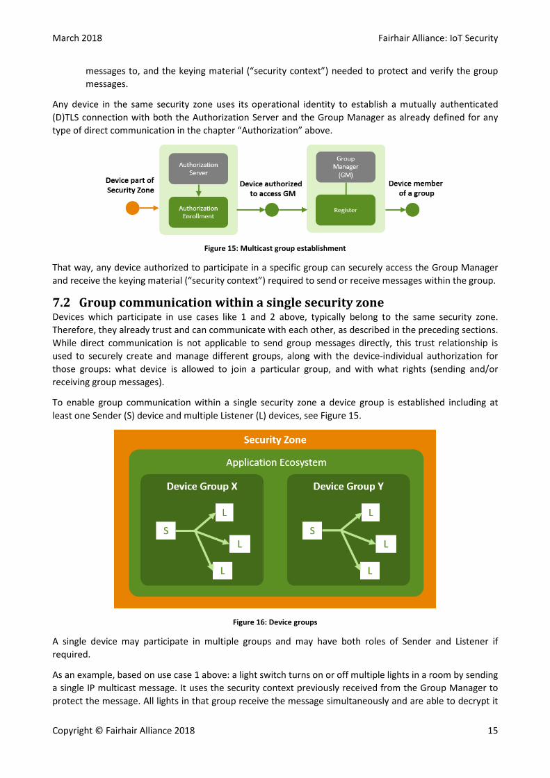
7.2 Group communication within a single security zone Devices which participate in use cases like 1 and 2 above, typically belong to the same security zone. Therefore, they already trust and can communicate with each other, as described in the preceding sections. While direct communication is not applicable to send group messages directly, this trust relationship is used to securely create and manage different groups, along with the device-individual authorization for those groups: what device is allowed to join a particular group, and with what rights (sending and/or receiving group messages).
To enable group communication within a single security zone a device group is established including at least one Sender (S) device and multiple Listener (L) devices, see Figure 15.
Figure 16: Device groups
A single device may participate in multiple groups and may have both roles of Sender and Listener if required.
As an example, based on use case 1 above: a light switch turns on or off multiple lights in a room by sending a single IP multicast message. It uses the security context previously received from the Group Manager to protect the message. All lights in that group receive the message simultaneously and are able to decrypt it
Fairhair Alliance: IoT Security March 2018
16 Copyright © Fairhair Alliance 2018
and verify that it came from a legitimate sender (i.e., the light switch). The overall concept ensures that this happens both securely and still within a reasonable delay (e.g. within less than 200ms) to satisfy the required user experience.
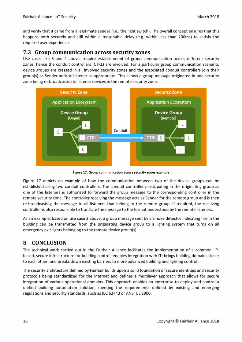
7.3 Group communication across security zones Use cases like 3 and 4 above, require establishment of group communication across different security zones, hence the conduit controllers (CTRL) are involved. For a particular group communication scenario, device groups are created in all involved security zones and the associated conduit controllers join their group(s) as Sender and/or Listener as appropriate. This allows a group message originated in one security zone being re-broadcasted to listener devices in the remote security zone.
Figure 17: Group communication across security zones example
Figure 17 depicts an example of how the communication between two of the device groups can be established using two conduit controllers. The conduit controller participating in the originating group as one of the listeners is authorized to forward the group message to the corresponding controller in the remote security zone. The controller receiving the message acts as Sender for the remote group and is then re-broadcasting the message to all listeners that belong to the remote group. If required, the receiving controller is also responsible to translate the message to the format understood by the remote listeners.
As an example, based on use case 3 above: a group message sent by a smoke detector indicating fire in the building can be transmitted from the originating device group to a lighting system that turns on all emergency exit-lights belonging to the remote device group(s).
8 CONCLUSION The technical work carried out in the Fairhair Alliance facilitates the implementation of a common, IP-based, secure infrastructure for building control; enables integration with IT; brings building domains closer to each other; and breaks down existing barriers to more advanced building and lighting control.
The security architecture defined by Fairhair builds upon a solid foundation of secure identities and security protocols being standardized for the Internet and defines a multilayer approach that allows for secure integration of various operational domains. This approach enables an enterprise to deploy and control a unified building automation solution, meeting the requirements defined by existing and emerging regulations and security standards, such as IEC 62443 or ANSI UL 2900.

March 2018 Fairhair Alliance: IoT Security
Copyright © Fairhair Alliance 2018 17
As per the current timeline, a detailed specification of the security architecture is planned to be available in Q1 2019. The specification enables manufacturers and providers of IP-based building control services to implement a Fairhair-compliant solution.
9 REFERENCES
[1] "ISA/IEC 62443," ISA/IEC, [Online]. Available: http://isa99.isa.org/Public/Information/The-62443-Series-Overview.pdf.
[2] "UL 2900," UL, [Online]. Available: https://industries.ul.com/cybersecurity/ul-2900-standards-process.
[3] IEEE, "802.1AR-2009 - IEEE Standard for Local and metropolitan area networks - Secure Device Identity," 2009. [Online]. Available: https://standards.ieee.org/findstds/standard/802.1AR-2009.html.
[4] Seitz, Selander, Wahlstroem, Erdtman and Tschofenig, "Authentication and Authorization for Constrained Environments," February 2018. [Online]. Available: https://tools.ietf.org/html/draft-ietf-ace-oauth-authz-10.
[5] Pritikin, Richardson, Behringer and Watsen, "Bootstrapping Remote Secure Key Infrastructures (BRSKI)," October 2017. [Online]. Available: https://tools.ietf.org/html/draft-ietf-anima-bootstrapping-keyinfra-09.
[6] van der Stok, "EST over secure CoAP (EST-coaps)," January 2018. [Online]. Available: https://tools.ietf.org/html/draft-vanderstok-ace-coap-est-04.
[7] Pritikin, Yee and Harkins, "Enrollment over Secure Transport, RFC7030," October 2013. [Online]. Available: https://tools.ietf.org/html/rfc7030.
[8] Lear, "Manufacturer Usage Description Specification," [Online]. Available: https://tools.ietf.org/html/draft-ietf-opsawg-mud-15.
[9] Tiloca, Selander, Palombini and Park, "Secure group communication for CoAP," March 2018. [Online]. Available: https://tools.ietf.org/html/draft-ietf-core-oscore-groupcomm-01.
[10] Tiloca and Park, "Joining OSCORE groups in ACE," March 2018. [Online]. Available: https://tools.ietf.org/html/draft-tiloca-ace-oscoap-joining-03.
[11] Rahman and Dijk, "Group Communication for the Constrained Application Protocol (CoAP), RFC7390," October 2014. [Online]. Available: https://tools.ietf.org/html/rfc7390.