rego internal valves & accessories · rego ® internal valves & accessories ... means of...
TRANSCRIPT

85
Internal Valves &
Accessories
RegO® Internal Valves & Accessories
LP-Gas Internal Valves
Safety WarningPurposeIn its continuing quest for safety, REGO® publishes a series of bulletins explaining the hazards associated withthe use, misuse, and aging of LP-Gas valves and regulators. It is hoped that these factual bulletins will makeclear to LP-Gas dealer managers and service personnel, that the utmost care and attention must be used in theinstallation, inspection, and maintenance of these products, or problems could occur which would result ininjuries and property damage.
The National Fire Protection Association Pamphlet #58, “Storage and Handling of Liquified Petroleum Gases’’states in section 1-6 that “In the interest of safety, all persons employed in handling LP-Gases shall be trained inproper handling and operating procedures’’. These “REGO® Safety Warnings’’ may be useful in training newemployees and reminding older employees of hazards that can occur.
It is recommended that all employees be furnished with a copy of NPGA Safety Pamphlet 306-88 “LPGasRegulator and Valve Inspection and Maintenance, 111-81 Limitations of Excess Flow Check Valves for LP-Gas,and 113-78 Safety Considerations in Bobtail Deliveries.’’
Nature of WarningsIt is recognized that warnings should be as brief as possible, but thefactors involved in internal valve and excess flow valve failures to per-form are not simple. They need to be fully understood. If there is a sim-ple
Make sure that the internal valve’s excess flow feature really clos-es when the flow exceeds rated closing flow, and that the valve willshut-off.
This bulletin is not intended to be an exhaustive treatment of internalvalves, and certainly does not cover all safety practices that should befollowed in installation, operation and maintenance of LP-Gas sys-tems, which include internal valves.
Internal valves must be closed on Cargo Vehicles when travelingon public roads and highways. The valve should only be openwhen pumping. Per MC 330 or 331, internal valves must also beequipped with remote closure system, when used on transports orbobtails.
There are two types of internal valves being used on storage tanks,transports and bobtails — spring loaded internal valves and differen-tial pressure internal valves. They both provide positive shut-off whenproduct is not being withdrawn and may include excess flow protectionfor the system during transfer operations.
Spring Loaded Internal Valves
Spring loaded internal valves are manually opened by levers, bymeans of fuse linked cable mechanisms or pneumatic or hydraulicactuators. They incorporate an excess flow feature that will close thevalve when the flow through the valve exceeds its rate of flow. Thesevalves should never be locked open by means of wires, chains, pegsor other devices.
Testing
Testing should be completed on a periodic basis.
1. To check operation of a spring loaded valve, activate the remotecontrol to close the valve while unit is pumping. If the meter indicatorflow continues, the valve should be repaired immediately.
2. Testing excess flow feature.The National Propane Gas Association Safety Bulletin #113-78 states:“In order to test an excess flow valve in a piping system, the flowthrough the valve must be made to exceed the valve’s closing rating.’’
The exact procedure used may vary with the installation, advisabilityof gas discharge and availability of equipment.
In general, most testing makes use of the fact that the excess flowvalves are “surge sensitive’’ and will close quicker under a suddenflow surge than under steady flow. A sufficient surge can often becreated by using a quick open/close valve to control sudden, momen-tary flow into a tank or piping section containing very low pressure. Anaudible click from the excess flow valve (and corresponding stoppageof flow) indicates its closure.
This testing should only be attempted by trained personnel familiarwith the process. If no one at the facility has experience in propertesting, outside expert help should be obtained.
A test involving venting gas to the atmosphere is hazardous andmay be impractical, or illegal.
Any test of any excess flow valve will not prove that the valve willclose in an emergency situation, due to reasons cited before. Thistest will only check the valves condition, and the flow rate sizing forthose test conditions.
3. Tight Shut-Off — A test should be made to insure the internal valvewill give a gas tight seal when the valve is in the closed position. Thiswill require removal of all product downstream from the internal valve,to insure the valve will give 100% seal when in the closed position. Ifthe internal valve does not give 100% seal the valve should berepaired immediately.
86
Inte
rnal
Val
ves
& A
cces
sori
esRegO® Internal Valves & Accessories
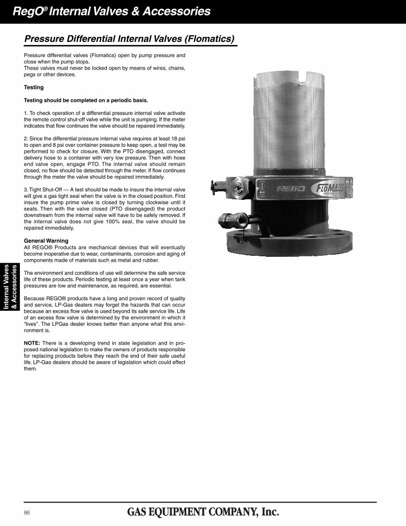
Pressure differential valves (Flomatics) open by pump pressure andclose when the pump stops.These valves must never be locked open by means of wires, chains,pegs or other devices.
Testing
Testing should be completed on a periodic basis.
1. To check operation of a differential pressure internal valve activatethe remote control shut-off valve while the unit is pumping. If the meterindicates that flow continues the valve should be repaired immediately.
2. Since the differential pressure internal valve requires at least 18 psito open and 8 psi over container pressure to keep open, a test may beperformed to check for closure. With the PTO disengaged, connectdelivery hose to a container with very low pressure. Then with hoseend valve open, engage PTO. The internal valve should remainclosed, no flow should be detected through the meter. If flow continuesthrough the meter the valve should be repaired immediately.
3. Tight Shut-Off — A test should be made to insure the internal valvewill give a gas tight seal when the valve is in the closed position. Firstinsure the pump prime valve is closed by turning clockwise until itseats. Then with the valve closed (PTO disengaged) the productdownstream from the internal valve will have to be safely removed. Ifthe internal valve does not give 100% seal, the valve should berepaired immediately.
General WarningAll REGO® Products are mechanical devices that will eventuallybecome inoperative due to wear, contaminants, corrosion and aging ofcomponents made of materials such as metal and rubber.
The environment and conditions of use will determine the safe servicelife of these products. Periodic testing at least once a year when tankpressures are low and maintenance, as required, are essential.
Because REGO® products have a long and proven record of qualityand service, LP-Gas dealers may forget the hazards that can occurbecause an excess flow valve is used beyond its safe service life. Lifeof an excess flow valve is determined by the environment in which it“lives’’. The LPGas dealer knows better than anyone what this envi-ronment is.
NOTE: There is a developing trend in state legislation and in pro-posed national legislation to make the owners of products responsiblefor replacing products before they reach the end of their safe usefullife. LP-Gas dealers should be aware of legislation which could effectthem.
Pressure Differential Internal Valves (Flomatics)
87
Internal Valves &
Accessories
RegO® Internal Valves & Accessories
Manual Internal ValvesA3200 Series
General Information
Manual Internal Valves are designed for a variety of uses in LP-Gasand anhydrous ammonia service. In addition, accessories allow mostof them to be actuated manually, by cable or with air.
Installation, usage and maintenance of this product must be in com-pliance with all REGO® instructions, as well as requirements and pro-visions of NFPA # 58, DOT, ANSI, and all applicable federal, state,provincial, and local standards, codes, regulations and laws.
These valves must remain in the closed position except during prod-uct transfer. A line break downstream of the pump may fail to actuatethe excess flow valve as the pump may limit flow. If break occurs in thesystem, or the excess flow closes, immediately shut down the system.
Inspection and maintenance on a periodic basis is essential.Installation and maintenance must be performed only by qualified per-sonnel.Be sure all instructions are read and understood before installationand operation of these valves.
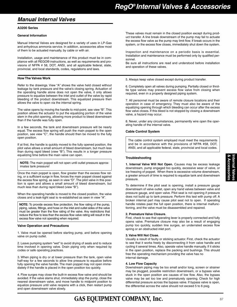
How The Valves Work
Refer to the drawings. View “A’’ shows the valve held closed withoutleakage by tank pressure and the valve’s closing spring. Actuation ofthe operating handle alone does not open the valve, it only allowspressure to equalize between the inlet and outlet of the valve by rapidbleeding of the product downstream. This equalized pressure thenallows the valve to open via the internal spring.
The valve opens by moving the handle to mid-point, see view “B’’. Thisposition allows the actuator to put the equalizing portion of the valvestem in the pilot opening, allowing more product to bleed downstreamthan if the handle was fully open.
In a few seconds, the tank and downstream pressure will be nearlyequal. The excess flow spring will push the main poppet to the openposition, see view “C’’, the handle should then be moved to the fullyopen position.
If at first, the handle is quickly moved to the fully opened position, thepilot valve allows a small amount of bleed downstream, but much lessthan during rapid bleed (view “B’’). This results in a longer pressureequalizing time before the main valve can open.
NOTE: The main poppet will not open until outlet pressure approx-imates tank pressure!
Once the main poppet is open, flow greater than the excess flow rat-ing, or a sufficient surge in flow, forces the main poppet closed againstthe excess flow spring, as seen in view “D’’. The pilot valve in this posi-tion is open and allows a small amount of bleed downstream, butmuch less than during rapid bleed (view “B’’).
When the operating handle is moved to the closed position, the valvecloses and a leak-tight seal is re-established as seen in view “A”.
NOTE: To provide excess flow protection, the flow rating of the pump,piping, valves, fittings, and hose on the inlet and outlet sides of the valvemust be greater than the flow rating of the valve. Any restrictions thatreduce the flow to less than the excess flow valve rating will result in theexcess flow valve not operating when required.
Valve Operation and Precautions
1. Valve must be opened before starting pump, and before openingvalve on pump outlet.
2. Leave pumping system “wet’’ to avoid drying of seals and to reducetime involved in opening valve. Drain piping only when required bycodes or safe operating practices.
3. When piping is dry or at lower pressure than the tank, open valvehalf-way for a few seconds to allow line pressure to equalize beforefully opening the valve handle. The main poppet may not open imme-diately if the handle is placed in the open position too quickly.
4. Flow surges may close the built-in excess flow valve and should beavoided. If the valve slams shut, immediately stop the pump, close thenearest downstream valve, and move handle to midpoint position toequalize pressure until valve reopens with a click, then restart pumpand open downstream valve slowly.
5. Always keep valve closed except during product transfer.
6. Completely open all valves during pumping. Partially closed or throt-tle type valves may prevent excess flow valve from closing whenrequired, even in a properly designed piping system.
7. All personnel must be aware of remote closure locations and theiroperation in case of emergency. They must also be aware of theequalizing opening through which bleeding can occur after the excessflow valve closes. If this bleed is not stopped by closing a downstreamvalve, a hazard may occur.
8. Never, under any circumstances, permanently wire open the oper-ating handle of the internal valve.
Cable Control System
The cable control system employed must meet the requirementsand be in accordance with the provisions of NFPA #58, DOT,ANSI, and all applicable federal, state, provincial and local codes.
Troubleshooting
1. Internal Valve Will Not Open. Causes may be excess leakagedownstream, pump engaged too quickly, excessive wear of valve, orice freezing of poppet. When there is excessive volume downstream,a greater amount of time is required to equalize tank and downstreampressure.
To determine if the pilot seat is opening, install a pressure gaugedownstream of valve outlet, open any hand valves between valve andpressure gauge, and open valve. Pilot seat is not opening if pressuredoes not build up to tank pressure. Perform this test with pump off. Abroken internal part may cause pilot seat not to open. If operatinghandle rotates past the full open position, there is internal malfunc-tioning, and the valve must be disassembled and repaired.
2. Premature Valve Closure.First, check to see that operating lever is properly connected and fullyopens valve. Premature closure may also be a result of engagingpump too quickly, sudden line surges, an underrated excess flowspring or an obstructed inlet port.
3. Valve Will Not Close.Usually a result of faulty or sticking actuator. First, check the actuatorto see that it works freely by disconnecting it from valve handle andcycling it several times. Also, operate valve handle manually. If it sticksin the open position, replace the packing and bushings. This shouldfree the operating mechanism providing the valve has nointernal damage.
4. Low Flow CapacityDownstream piping may be too small and/or long, screen or strainermay be plugged, possible restriction downstream, or a bypass valvestuck in the open position are causes of low flow. Also, the bypassvalve may be set too low and prematurely opening. Check for highdifferential pressure across the bypass valve. If bypass valve is open,the differential across the valve should not exceed 5 to 6 psig.
88
Inte
rnal
Val
ves
& A
cces
sori
esRegO® Internal Valves & Accessories
Potential problems may be eliminated with preventive internal valvemaintenance. Perform the following steps once a month:
1. Check to see that the operating lever moves freely and smoothly.There should be no leakage around the lower stem or seal housing.Leakage requires replacement of the seal housing packing. A stickinglever indicates trapped foreign material or mechanism wear.
2. Check both seat discs for tight closure. Close valve and exhaustdownstream pressure. Be sure piping is warmed to an ambient tem-perature. Close the first downstream valve and note pressure buildupbetween the closed valves with a pressure gauge. If leakage occurs,replace both seat discs.
3. Inspect, clean and oil all operating controls. Check controls to seethat they open fully, but do not overtravel the valve operating lever. Seethat they work freely to close the valve. Worn parts should bereplaced.
4. Remove valve if the tank is to be steam cleaned. Heat may damagethe valve’s seals.
5. Valve is not designed for water service. After tank is hydrostaticallytested, immediately remove all water and allow tank to thoroughly dryout before installing valve.
A3209D Series, 1¼” StraightA3209DT Series, 1¼” StraightA3211D Series 1½ StraightA3212R Series, 2” StraightA3212RT Series 2” Tee BodyA3213R Series, 3” StraightA3213T Series 3” Tee Body
A3217A Series, 3” FlangedA3217DA Series,3” Double Flanged
A3219FA Series, 4” Flanged
Maintenance
89
Internal Valves &
Accessories
RegO® Internal Valves & Accessories
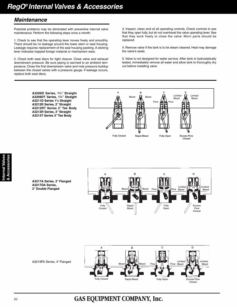
1-1⁄4" Threaded Internal Valve for Small Capacity PumpingSystems and Bobtail Vapor EqualizationDesigned primarily for use with LP-Gas and anhydrous ammonia as amain valve on small capacity pumping systems, NH3 nurse tanks andin-line installations. It may also be installed in the vapor equalizingopening on bobtail delivery trucks. Installation is quick and easy, and itfits in both full and half couplings, as well as, in-line applications. Thevalve may be actuated manually by hand or cable.
A3209PA
Straight Through 1-1⁄2” Internal Valve
Designed primarily for use with LP-Gas and anhydrous ammonia as amain valve on pumping systems, and in-line installations. Installation isquick and easy, and it fits in both full and half couplings, as well as, in-line applications. The valve may be opened manually by hand or pneu-matic actuator.
A3209TLA3209TL
Part NumberInlet
ConnectionM. NPT
OutletConnectionF. NPT
Closing FlowLP-Gas VaporCapacity**
(SCFH/Propane)Accessories
LP-Gas NH3 25 PSIG 100 PSIGThermalLatch
PneumaticActuators
A3209D050 1¼” 1¼” 50 45 13,300 22,900
A3209TL A3209PAA3209PAF
A3209D080 1¼” 1¼” 80 72 15,700 26,700
A3209DT050 1¼” 1¼” 50 45 13,300 22,900
A3209DT080 1¼” 1¼” 80 72 15,700 26,700
A3209PAF
A3209D
A3209DT
UL®
PartNumber
Inlet M-NPT Outlet F-NPT
Closing Flow GPM LP-Gas Vapor Capacity
(SCFH/Propane)Accessories
Half Coupling Full Coupling25 PSIG Inlet
100 PSIGInlet
ThermalLatch
Pneumatic ActuatorLP-Gas NH3 LP-Gas NH3
A3211D080 1½” 1½” 80 72 63 67 15,700 26,700A3209TL A3209PAF
A3211D110 1½” 1½” 110 99 84 76 N/A N/A
A3211D
UL®
90
RegO® Internal Valves & AccessoriesIn
tern
al V
alve
s &
Acc
esso
ries
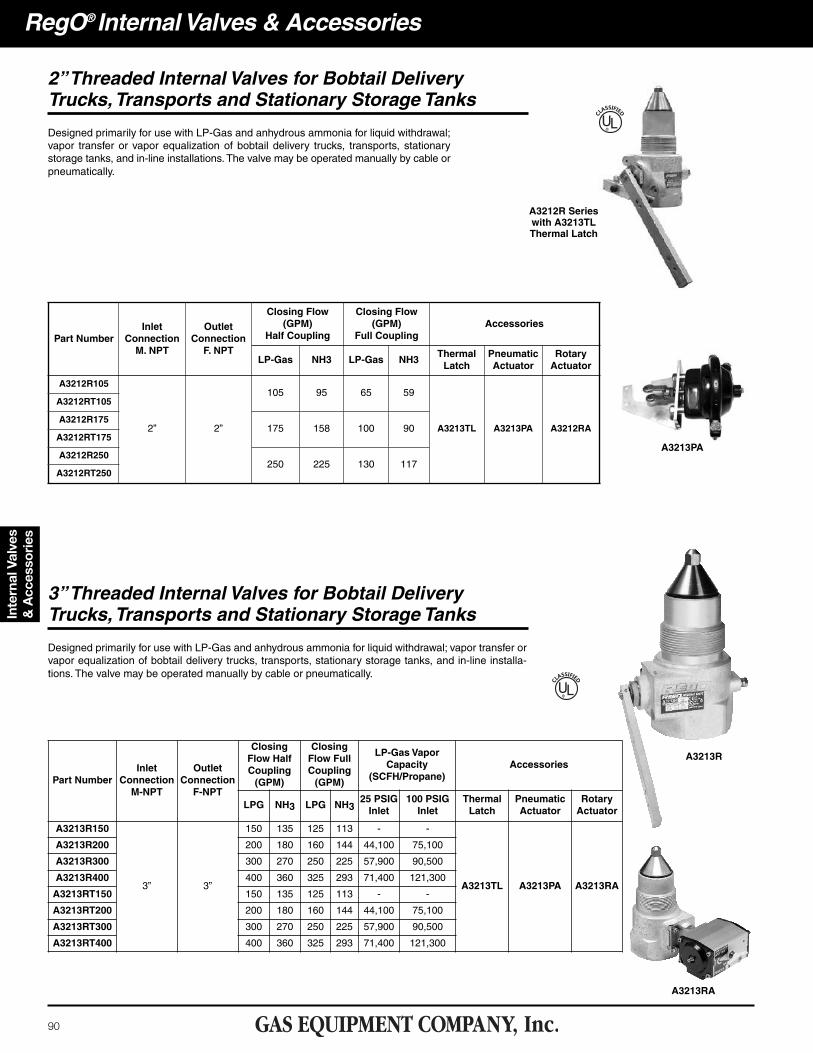
2” Threaded Internal Valves for Bobtail DeliveryTrucks, Transports and Stationary Storage Tanks
Designed primarily for use with LP-Gas and anhydrous ammonia for liquid withdrawal;vapor transfer or vapor equalization of bobtail delivery trucks, transports, stationarystorage tanks, and in-line installations. The valve may be operated manually by cable orpneumatically.
A3212R Serieswith A3213TLThermal Latch
UL®
Part NumberInlet
ConnectionM. NPT
OutletConnectionF. NPT
Closing Flow(GPM)
Half Coupling
Closing Flow(GPM)
Full CouplingAccessories
LP-Gas NH3 LP-Gas NH3ThermalLatch
PneumaticActuator
RotaryActuator
A3212R105
2” 2”
105 95 65 59
A3213TL A3213PA A3212RA
A3212RT105
A3212R175175 158 100 90
A3212RT175
A3212R250250 225 130 117
A3212RT250
A3213R
3” Threaded Internal Valves for Bobtail DeliveryTrucks, Transports and Stationary Storage Tanks
Designed primarily for use with LP-Gas and anhydrous ammonia for liquid withdrawal; vapor transfer orvapor equalization of bobtail delivery trucks, transports, stationary storage tanks, and in-line installa-tions. The valve may be operated manually by cable or pneumatically.
Part NumberInlet
ConnectionM-NPT
OutletConnectionF-NPT
ClosingFlow HalfCoupling(GPM)
ClosingFlow FullCoupling(GPM)
LP-Gas VaporCapacity
(SCFH/Propane)Accessories
LPG NH3 LPG NH325 PSIGInlet
100 PSIGInlet
ThermalLatch
PneumaticActuator
RotaryActuator
A3213R150
3” 3”
150 135 125 113 - -
A3213TL A3213PA A3213RA
A3213R200 200 180 160 144 44,100 75,100
A3213R300 300 270 250 225 57,900 90,500
A3213R400 400 360 325 293 71,400 121,300
A3213RT150 150 135 125 113 - -
A3213RT200 200 180 160 144 44,100 75,100
A3213RT300 300 270 250 225 57,900 90,500
A3213RT400 400 360 325 293 71,400 121,300
UL®
A3213PA
A3213RA
91
Internal Valves &
Accessories
RegO® Internal Valves & Accessories
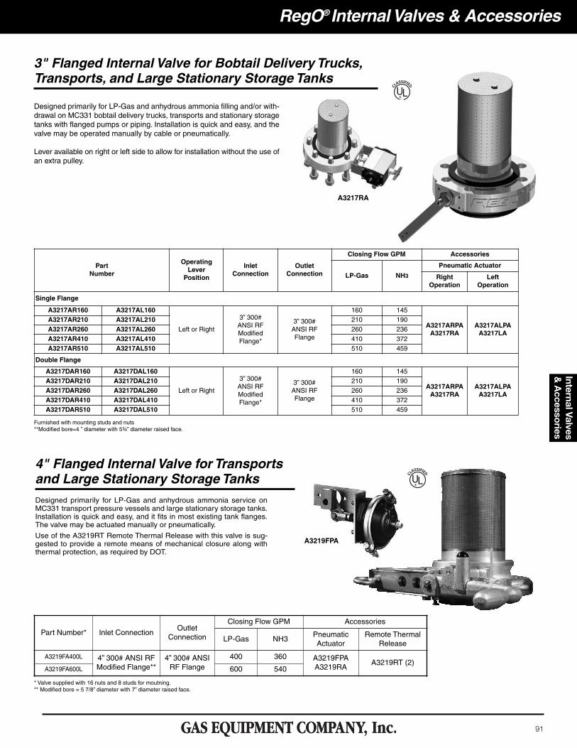
Designed primarily for LP-Gas and anhydrous ammonia filling and/or with-drawal on MC331 bobtail delivery trucks, transports and stationary storagetanks with flanged pumps or piping. Installation is quick and easy, and thevalve may be operated manually by cable or pneumatically.
Lever available on right or left side to allow for installation without the use ofan extra pulley.
3" Flanged Internal Valve for Bobtail Delivery Trucks,Transports, and Large Stationary Storage Tanks
PartNumber
Operating Lever Position
Inlet Connection
Outlet Connection
Closing Flow GPM Accessories
LP-Gas NH3
Pneumatic Actuator
RightOperation
LeftOperation
Single Flange
A3217AR160 A3217AL160
Left or Right
3” 300#ANSI RFModifiedFlange*
3” 300#ANSI RFFlange
160 145
A3217ARPAA3217RA
A3217ALPAA3217LA
A3217AR210 A3217AL210 210 190
A3217AR260 A3217AL260 260 236
A3217AR410 A3217AL410 410 372
A3217AR510 A3217AL510 510 459
Double Flange
A3217DAR160 A3217DAL160
Left or Right
3” 300#ANSI RFModifiedFlange*
3” 300#ANSI RFFlange
160 145
A3217ARPAA3217RA
A3217ALPAA3217LA
A3217DAR210 A3217DAL210 210 190
A3217DAR260 A3217DAL260 260 236
A3217DAR410 A3217DAL410 410 372
A3217DAR510 A3217DAL510 510 459
Furnished with mounting studs and nuts**Modified bore=4�” diameter with 5¾” diameter raised face.
UL®
4" Flanged Internal Valve for Transportsand Large Stationary Storage Tanks
A3219FPA
Designed primarily for LP-Gas and anhydrous ammonia service onMC331 transport pressure vessels and large stationary storage tanks.Installation is quick and easy, and it fits in most existing tank flanges.The valve may be actuated manually or pneumatically.
Use of the A3219RT Remote Thermal Release with this valve is sug-gested to provide a remote means of mechanical closure along withthermal protection, as required by DOT.
UL®
Part Number* Inlet ConnectionOutlet
Connection
Closing Flow GPM Accessories
LP-Gas NH3PneumaticActuator
Remote ThermalRelease
A3219FA400L 4” 300# ANSI RFModified Flange**
4” 300# ANSIRF Flange
400 360 A3219FPAA3219RA
A3219RT (2)A3219FA600L 600 540
* Valve supplied with 16 nuts and 8 studs for moutning.** Modified bore = 5 7/8” diameter with 7” diameter raised face.
A3217RA
92
Inte
rnal
Val
ves
& A
cces
sori
esRegO® Internal Valves & Accessories
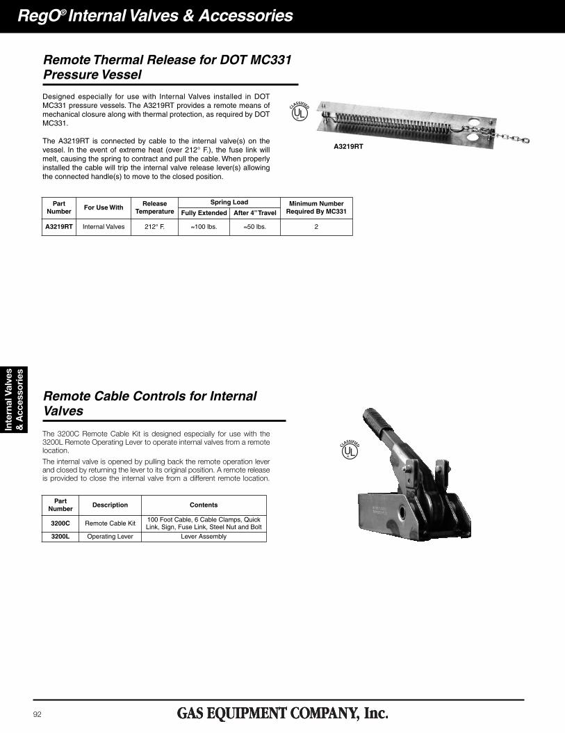
Remote Thermal Release for DOT MC331Pressure Vessel
Designed especially for use with Internal Valves installed in DOTMC331 pressure vessels. The A3219RT provides a remote means ofmechanical closure along with thermal protection, as required by DOTMC331.
The A3219RT is connected by cable to the internal valve(s) on thevessel. In the event of extreme heat (over 212° F.), the fuse link willmelt, causing the spring to contract and pull the cable. When properlyinstalled the cable will trip the internal valve release lever(s) allowingthe connected handle(s) to move to the closed position.
The 3200C Remote Cable Kit is designed especially for use with the3200L Remote Operating Lever to operate internal valves from a remotelocation.
The internal valve is opened by pulling back the remote operation leverand closed by returning the lever to its original position. A remote releaseis provided to close the internal valve from a different remote location.
Remote Cable Controls for InternalValves
A3219RT
UL®
PartNumber
For Use WithRelease
TemperatureSpring Load Minimum Number
Required By MC331Fully Extended After 4” Travel
A3219RT Internal Valves 212° F. ≈100 lbs. ≈50 lbs. 2
UL®
PartNumber
Description Contents
3200C Remote Cable Kit 100 Foot Cable, 6 Cable Clamps, QuickLink, Sign, Fuse Link, Steel Nut and Bolt
3200L Operating Lever Lever Assembly
93
Internal Valves &
Accessories
RegO® Internal Valves & Accessories
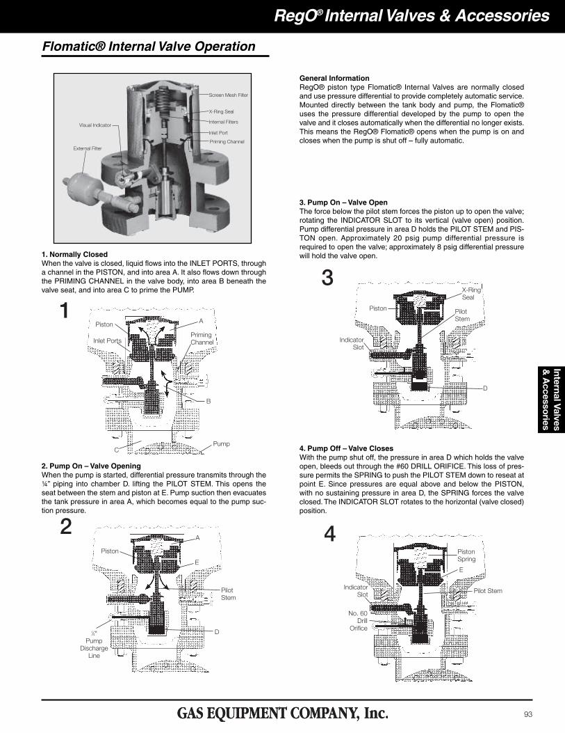
Flomatic® Internal Valve Operation
General InformationRegO® piston type Flomatic® Internal Valves are normally closedand use pressure differential to provide completely automatic service.Mounted directly between the tank body and pump, the Flomatic®uses the pressure differential developed by the pump to open thevalve and it closes automatically when the differential no longer exists.This means the RegO® Flomatic® opens when the pump is on andcloses when the pump is shut off – fully automatic.
1. Normally ClosedWhen the valve is closed, liquid flows into the INLET PORTS, througha channel in the PISTON, and into area A. It also flows down throughthe PRIMING CHANNEL in the valve body, into area B beneath thevalve seat, and into area C to prime the PUMP.
3. Pump On – Valve OpenThe force below the pilot stem forces the piston up to open the valve;rotating the INDICATOR SLOT to its vertical (valve open) position.Pump differential pressure in area D holds the PILOT STEM and PIS-TON open. Approximately 20 psig pump differential pressure isrequired to open the valve; approximately 8 psig differential pressurewill hold the valve open.
2. Pump On – Valve OpeningWhen the pump is started, differential pressure transmits through the¼” piping into chamber D. lifting the PILOT STEM. This opens theseat between the stem and piston at E. Pump suction then evacuatesthe tank pressure in area A, which becomes equal to the pump suc-tion pressure.
4. Pump Off – Valve ClosesWith the pump shut off, the pressure in area D which holds the valveopen, bleeds out through the #60 DRILL ORIFICE. This loss of pres-sure permits the SPRING to push the PILOT STEM down to reseat atpoint E. Since pressures are equal above and below the PISTON,with no sustaining pressure in area D, the SPRING forces the valveclosed. The INDICATOR SLOT rotates to the horizontal (valve closed)position.

RegO® Internal Valves & Accessories
Flomatic® Internal Valves for Bobtail Delivery Trucks,Transports and Large Stationary Storage Tanks
Designed primarily for LP-Gas and anhydrous ammonia liquid with-drawal on MC331 bobtail delivery trucks, transports and large station-ary storage containers with flanged connections. The valve is fully auto-matic, opening and closing as the pump is turned on or off.
A7853A 1⁄4" Three-WayQuick-Acting Valve
94
Inte
rnal
Val
ves
& A
cces
sori
es
A7883FK
UL®
*Supplied with A7853A 3-way valve, A7884-201 filter, studs, nuts and gaskets.**With 413⁄16” diameter bore.***With 513⁄16” diameter bore.
PartNumber
Inlet ConnectionANSI Flange
Outlet ConnectionANSI Flange
StrainerWidth
BaseWidth
Overall Height(Approx.)
Height from Indicatorto Base
Accessories (included with Flomatic®)
Filter 3-Way Valve
A7883FK 3”-300#** 3”-300# 4¾” 8¼” 107⁄8” 413⁄16”A7884-201 A7853A
A7884FK 4”-300#*** 4”-300# 5¾” 10” 11¼” 415⁄16”
A7883 & A7884 AcessoriesUL®
Part Number Description For Use With
A7853PAF Pneumatic ActuatorA7883FK, A7884FK
A7853PA 1/4” Three-Way Valve
95
RegO® Internal Valves & AccessoriesInternal Valves &
Accessories
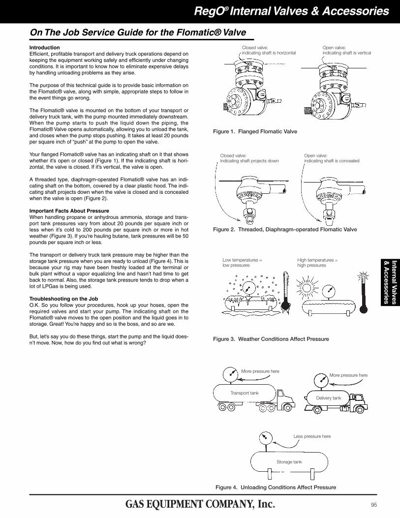
IntroductionEfficient, profitable transport and delivery truck operations depend onkeeping the equipment working safely and efficiently under changingconditions. It is important to know how to eliminate expensive delaysby handling unloading problems as they arise.
The purpose of this technical guide is to provide basic information onthe Flomatic® valve, along with simple, appropriate steps to follow inthe event things go wrong.
The Flomatic® valve is mounted on the bottom of your transport ordelivery truck tank, with the pump mounted immediately downstream.When the pump starts to push the liquid down the piping, theFlomatic® Valve opens automatically, allowing you to unload the tank,and closes when the pump stops pushing. It takes at least 20 poundsper square inch of “push’’ at the pump to open the valve.
Your flanged Flomatic® valve has an indicating shaft on it that showswhether it’s open or closed (Figure 1). If the indicating shaft is hori-zontal, the valve is closed. If it’s vertical, the valve is open.
A threaded type, diaphragm-operated Flomatic® valve has an indi-cating shaft on the bottom, covered by a clear plastic hood. The indi-cating shaft projects down when the valve is closed and is concealedwhen the valve is open (Figure 2).
Important Facts About PressureWhen handling propane or anhydrous ammonia, storage and trans-port tank pressures vary from about 20 pounds per square inch orless when it’s cold to 200 pounds per square inch or more in hotweather (Figure 3). If you’re hauling butane, tank pressures will be 50pounds per square inch or less.
The transport or delivery truck tank pressure may be higher than thestorage tank pressure when you are ready to unload (Figure 4). This isbecause your rig may have been freshly loaded at the terminal orbulk plant without a vapor equalizing line and hasn’t had time to getback to normal. Also, the storage tank pressure tends to drop when alot of LPGas is being used.
Troubleshooting on the JobO.K. So you follow your procedures, hook up your hoses, open therequired valves and start your pump. The indicating shaft on theFlomatic® valve moves to the open position and the liquid goes in tostorage. Great! You’re happy and so is the boss, and so are we.
But, let’s say you do these things, start the pump and the liquid does-n’t move. Now, how do you find out what is wrong?
On The Job Service Guide for the Flomatic® Valve
96
RegO® Internal Valves & AccessoriesIn
tern
al V
alve
s &
Acc
esso
ries
Step 1Immediately shut down the pump so you don’t cause possible dam-age to the seals or valves. Next:
1. Check all manual valves in the system to make certain they are open or closed as required for proper operation.
2. Check the liquid level in the transport or delivery tank. If the level is low, it may slow the transfer rate.
3. Check to assure that the pump rotates normally when power is applied. If not, inspect and repair as needed the power takeoff, universal joints, drive shaft and clutch, etc.
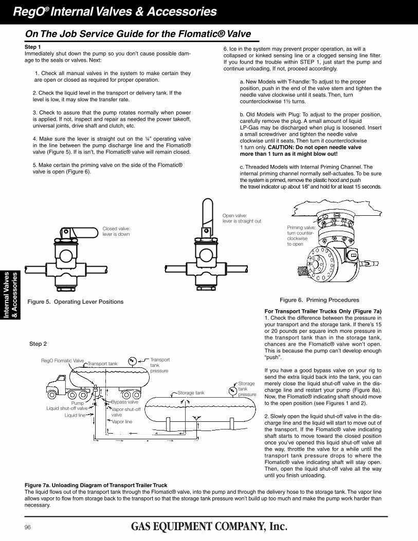
4. Make sure the lever is straight out on the ¼” operating valve in the line between the pump discharge line and the Flomatic® valve (Figure 5). If is isn’t, the Flomatic® valve will remain closed.
5. Make certain the priming valve on the side of the Flomatic® valve is open (Figure 6).
6. Ice in the system may prevent proper operation, as will a collapsed or kinked sensing line or a clogged sensing line filter. If you found the trouble within STEP 1, just start the pump and continue unloading, If not, proceed accordingly.
a. New Models with T-handle: To adjust to the proper position, push in the end of the valve stem and tighten the needle valve clockwise until it seats. Then, turn counterclockwise 1½ turns.
b. Old Models with Plug: To adjust to the proper position, carefully remove the plug. A small amount of liquid LP-Gas may be discharged when plug is loosened. Insert a small screwdriver and tighten the needle valve clockwise until it seats. Then turn it counterclockwise 1 turn only. CAUTION: Do not open needle valve more than 1 turn as it might blow out!
c. Threaded Models with Internal Priming Channel. The internal priming channel normally self-actuates. To be sure the system is primed, remove the plastic hood and push the travel indicator up about 1⁄8” and hold for at least 15 seconds.
Figure 7a. Unloading Diagram of Transport Trailer TruckThe liquid flows out of the transport tank through the Flomatic® valve, into the pump and through the delivery hose to the storage tank. The vapor lineallows vapor to flow from storage back to the transport so that the storage tank pressure won’t build up too much and make the pump work harder thannecessary.
For Transport Trailer Trucks Only (Figure 7a)1. Check the difference between the pressure inyour transport and the storage tank. If there’s 15or 20 pounds per square inch more pressure inthe transport tank than in the storage tank,chances are the Flomatic® valve won’t open.This is because the pump can’t develop enough“push’’.
If you have a good bypass valve on your rig tosend the extra liquid back into the tank, you canmerely close the liquid shut-off valve in the dis-charge line and restart your pump (Figure 8a).Now, the Flomatic® indicating shaft should moveto the open position (see Figures 1 and 2).
2. Slowly open the liquid shut-off valve in the dis-charge line and the liquid will start to move out ofthe transport. If the Flomatic® valve indicatingshaft starts to move toward the closed positiononce you’ve opened this liquid shut-off valve allthe way, throttle the valve for a while until thetransport tank pressure drops to where theFlomatic® valve indicating shaft will stay open.Then, open the liquid shut-off valve all the wayuntil you finish unloading.
On The Job Service Guide for the Flomatic® Valve
97
RegO® Internal Valves & AccessoriesInternal Valves &
Accessories
On The Job Service Guide for the Flomatic® Valve
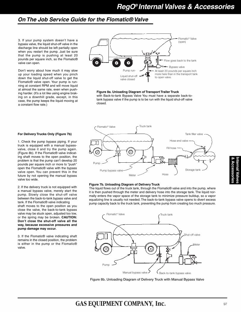
3. If your pump system doesn’t have abypass valve, the liquid shut-off valve in thedischarge line should be left partially openwhen you restart the pump. Just be surethat the pump is pushing at least 20pounds per square inch, so the Flomatic®valve can open.
Don’t worry about how much it may slowup your loading speed when you pinchdown the liquid shut-off valve to get theFlomatic® valve open. Your pump is run-ning at constant RPM and will move liquidat almost the same rate, even when push-ing harder. (It’s a lot like using engine brak-ing on a downhill grade, except, in thiscase, the pump keeps the liquid moving ata constant flow rate.)
Figure 8a. Unloading Diagram of Transport Trailer Truckwith Back-to-tank Bypass Valve You must have a separate back-to-tank bypass valve if the pump is to be run with the liquid shut-off valveclosed.
For Delivery Trucks Only (Figure 7b)
1. Check the pump bypass piping. If yourtruck is equipped with a manual bypass-valve, close it and try the pump again.(Figure 8b). If the Flomatic® valve indicat-ing shaft moves to the open position, theproblem is that the pump can’t develop 20pounds per square inch or more to “push’’open the Flomatic® valve with the bypassvalve open. You can prevent this in thefuture by not opening the manual bypassvalve too wide.
2. If the delivery truck is not equipped witha manual bypass valve, merely start thepump. Slowly close the shut-off valvebetween the back-to-tank bypass valve andtank. If the Flomatic® valve indicatingshaft moves to the open position as youclose the valve, the back-to-tank bypassvalve may be stuck open, adjusted too low,or the spring may be broken. CAUTION:Don’t close the shut-off valve all theway, because excessive pressures andpump damage may occur.
3. If the Flomatic® valve indicating shaftremains in the closed position, the problemis either in the pump or the Flomatic®valve.
Figure 7b. Unloading Diagram of Delivery TruckThe liquid flows out of the truck tank, through the Flomatic® valve and into the pump, whereit is then pushed through the meter and delivery hose into the storage tank. The liquid nor-mally enters the vapor space of the storage tank to minimize pressure buildup, so a vaporequalizing line is usually not needed. The back-to-tank bypass valve opens to divert excesspump capacity back to the truck tank, preventing the pump from creating too much pressure.

98
RegO® Internal Valves & AccessoriesIn
tern
al V
alve
s &
Acc
esso
ries
On The Job Service Guide for the Flomatic® Valve
USE EXTREME CARE AT ALL TIMES WHEN WORKING AROUND YOUR VEHICLE!Watch out for drive shafts and moving parts. It is common knowledge that serious injurycan result if any part of one’s body or clothing is caught in moving machinery.
If you manually open the Flomatic® valve, you are responsible for safely unloading the liq-uid and closing the valve when you’re through. If this procedure is being followed, underno circumstances must the valve be left unattended. The valve must never be permanentlyheld in the open position.
If you are not able to cause the Flomatic® valve indicating shaft tomove to the open position after completing the preceding steps, acomplete detailed diagnosis will have to be made.
In the meantime, you can actuate the flanged Flomatic® valve byusing a special wrench and attempt to unload manually (Figure 9).
If you still can’t unload by following the preceding steps, it is sug-gested that you unload by an alternate method, such as through thevalve normally used for liquid filling.
In any event, if you haven’t solved the problem and the unit stilldoesn’t operate properly, immediately take it out of service, have acomplete analysis made and repair as needed.
Be sure to obtain and keep available for quick referral theManufacturers’ Operation and Service Manuals for the valves, pump,meter and all operating equipment in the system.
99
RegO® Internal Valves & AccessoriesInternal Valves &
Accessories
IntroductionMost LP-Gas and anhydrous ammonia systems use pumps to moveliquid from one location to another. Unloading transport trailer tanksinto plant storage, loading delivery trucks, filling bulk tanks, engine fueltanks, portable cylinders, etc. and pressurizing LP-Gas vaporizers areonly a few of many such applications. A well-designed and properlyinstalled pumping system will perform well for some time, but eventu-ally problems occur requiring attention.
Finding out what is wrong, and getting it working again, can be atimeconsuming and confusing experience, unless one knows clearlyhow to proceed.
The purpose for this technical guide is to provide simple, step-by-stepguidelines for correcting LP-Gas and anhydrous ammonia pumpingdifficulties.
The procedure includes a preliminary checklist to help find out if thedifficulty can be corrected without taking anything apart. Then, itshows how to zero in on more serious problems by using a few pres-sure gauges to pinpoint the cause.
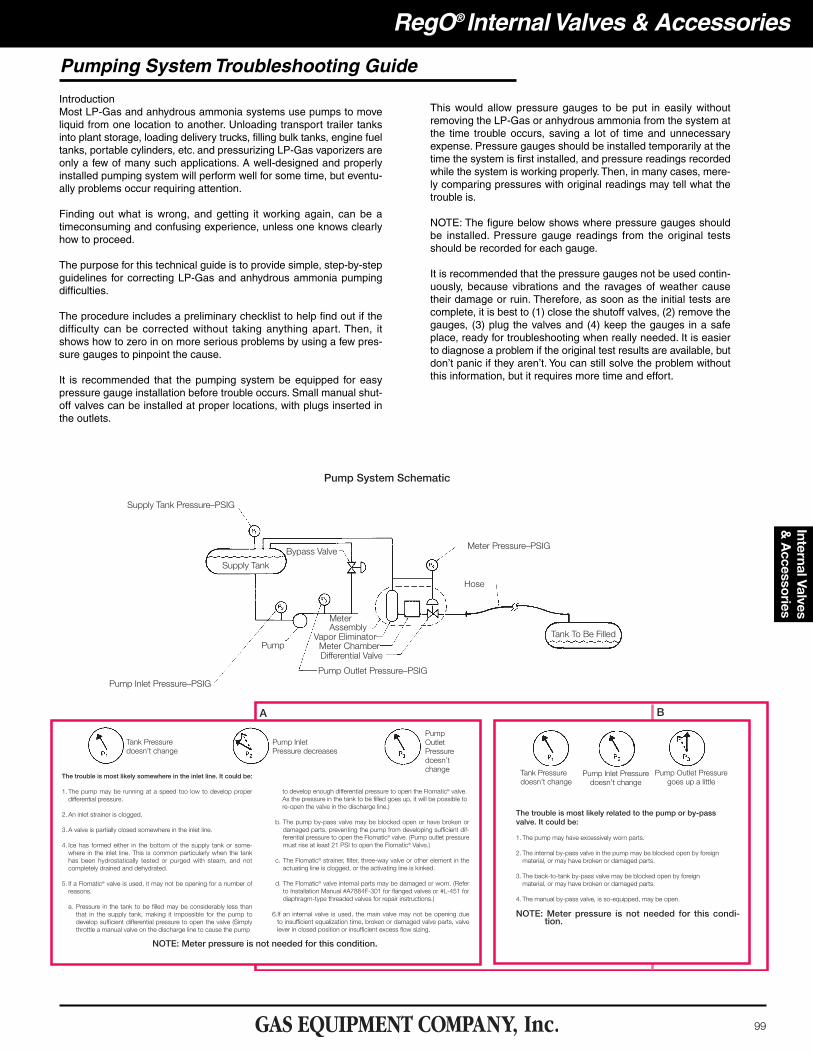
It is recommended that the pumping system be equipped for easypressure gauge installation before trouble occurs. Small manual shut-off valves can be installed at proper locations, with plugs inserted inthe outlets.
This would allow pressure gauges to be put in easily withoutremoving the LP-Gas or anhydrous ammonia from the system atthe time trouble occurs, saving a lot of time and unnecessaryexpense. Pressure gauges should be installed temporarily at thetime the system is first installed, and pressure readings recordedwhile the system is working properly. Then, in many cases, mere-ly comparing pressures with original readings may tell what thetrouble is.
NOTE: The figure below shows where pressure gauges shouldbe installed. Pressure gauge readings from the original testsshould be recorded for each gauge.
It is recommended that the pressure gauges not be used contin-uously, because vibrations and the ravages of weather causetheir damage or ruin. Therefore, as soon as the initial tests arecomplete, it is best to (1) close the shutoff valves, (2) remove thegauges, (3) plug the valves and (4) keep the gauges in a safeplace, ready for troubleshooting when really needed. It is easierto diagnose a problem if the original test results are available, butdon’t panic if they aren’t. You can still solve the problem withoutthis information, but it requires more time and effort.
Pumping System Troubleshooting Guide
100
RegO® Internal Valves & AccessoriesIn
tern
al V
alve
s &
Acc
esso
ries
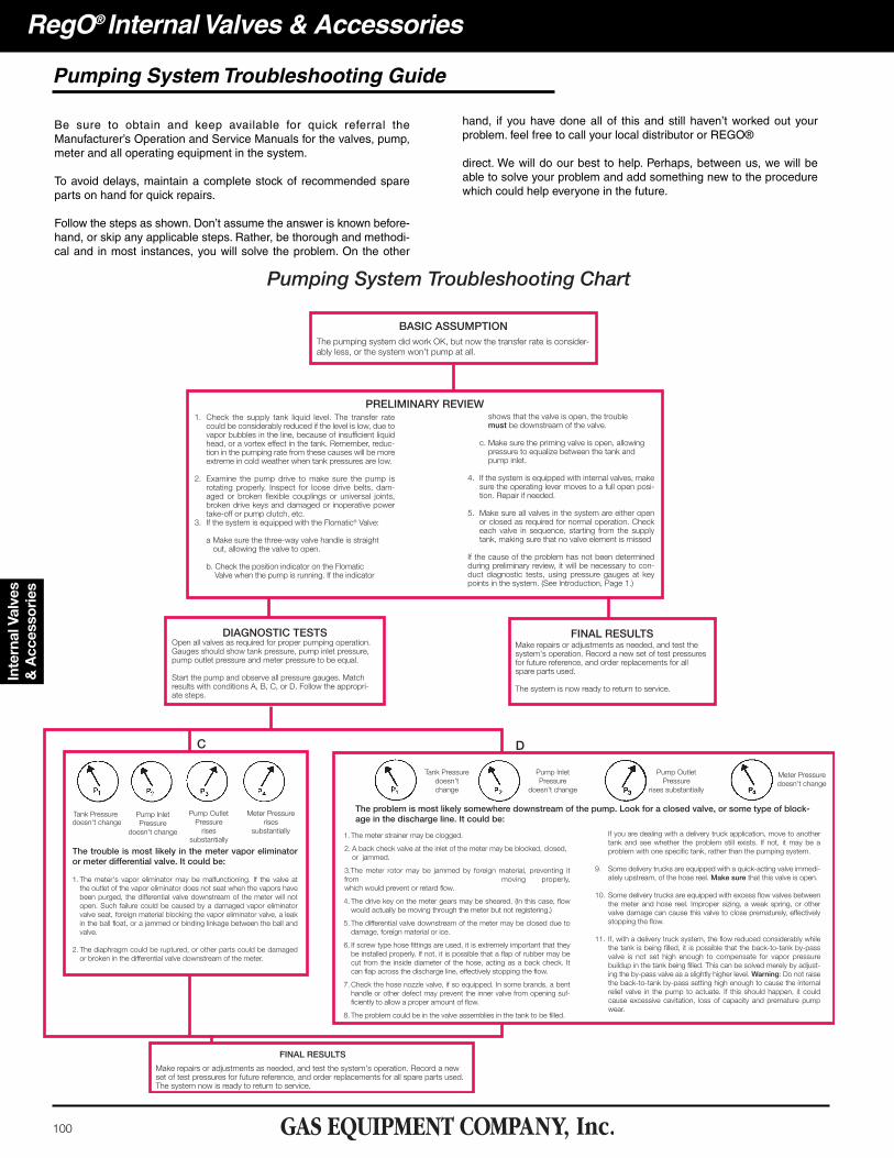
Be sure to obtain and keep available for quick referral theManufacturer’s Operation and Service Manuals for the valves, pump,meter and all operating equipment in the system.
To avoid delays, maintain a complete stock of recommended spareparts on hand for quick repairs.
Follow the steps as shown. Don’t assume the answer is known before-hand, or skip any applicable steps. Rather, be thorough and methodi-cal and in most instances, you will solve the problem. On the other
hand, if you have done all of this and still haven’t worked out yourproblem. feel free to call your local distributor or REGO®
direct. We will do our best to help. Perhaps, between us, we will beable to solve your problem and add something new to the procedurewhich could help everyone in the future.
Pumping System Troubleshooting Guide