proportional valve group - danfoss · sensing directional valve, to an advanced electrically...
TRANSCRIPT

Revision history Table of revisions
Date Changed Rev
June 2019 New EU Declaration of Conformity 0103
May 2019 Updated EU Declaration of Conformity, and minor changes 0102
May 2019 First edition 0101
Technical InformationPVG-EX 32 Proportional Valve Group
2 | © Danfoss | June 2019 BC290860493426en-000103

PVG-EX IntroductionProduct certification........................................................................................................................................................................5Warnings..............................................................................................................................................................................................5Nameplate description...................................................................................................................................................................6Description of the EX code h version........................................................................................................................................ 7EPL/Equipment category...............................................................................................................................................................7
General informationGeneral description......................................................................................................................................................................... 8Features................................................................................................................................................................................................8Inlets......................................................................................................................................................................................................8Work section housing..................................................................................................................................................................... 8Actuation methods.......................................................................................................................................................................... 9Sectional view................................................................................................................................................................................. 10PVG-EX modules overview......................................................................................................................................................... 11
PVP Inlet ModulesOpen Center PVP............................................................................................................................................................................13Open Center PVP with PPRV...................................................................................................................................................... 16Open center PVP with HPCO and PVE PPRV.........................................................................................................................19Closed Center PVP......................................................................................................................................................................... 22Closed Center PVP with PPRV....................................................................................................................................................24Closed center PVPV....................................................................................................................................................................... 26Closed center PVPV with PPRV..................................................................................................................................................27Closed center PVPVM with PPRV..............................................................................................................................................29Open/Closed center PVP with PPRV........................................................................................................................................31Open/Closed center PVPM......................................................................................................................................................... 34
PVP Inlet Module AccessoriesPVPC without Check Valve..........................................................................................................................................................36PVPC with Check Valve................................................................................................................................................................ 37
PVB Basic ModulesUncompensated PVB....................................................................................................................................................................39Uncompensated PVB with load drop check valve............................................................................................................. 42Uncompensated PVBZ with POC..............................................................................................................................................45Compensated PVB......................................................................................................................................................................... 46Dampened Compensated PVB..................................................................................................................................................49Dampened compensated PVB with LS A/B.......................................................................................................................... 52Compensated PVB with LS A/B................................................................................................................................................. 55Compensated high flow PVB..................................................................................................................................................... 59Compensated high flow PVB with LS A/B............................................................................................................................. 62Compensated PVBZ with POC...................................................................................................................................................66Compensated high flow PVBZ with POC...............................................................................................................................68Compensated high flow PVBZ with POC and manifold interface ............................................................................... 70
PVB Basic Modules AccessoriesPVLP Shock and Anti-Cavitation Valve...................................................................................................................................72PVLA Suction Valve........................................................................................................................................................................74
PVBS Main SpoolsPVBS fluid flow characteristics—Theoretical performance............................................................................................ 76
PVBS Main Spools Part NumbersFlow Control Spools—Closed Neutral Position.................................................................................................................. 81Flow Control Spools—Closed Neutral Position with A-float..........................................................................................85Flow Control Spools—Closed Neutral Position with B-float.......................................................................................... 86Flow Control Spools—Closed Neutral Position with A-float for PVMF...................................................................... 87Flow Control Spools—Closed Neutral Position with B-float for PVMF.......................................................................87Flow Control Spools—Closed Neutral Position for PVMR...............................................................................................88Flow Control Spools—Open/Closed Neutral Position..................................................................................................... 89Flow Control Spools—Open/Closed A and Closed B Position...................................................................................... 89
Technical InformationPVG-EX 32 Proportional Valve Group
Contents
© Danfoss | June 2019 BC290860493426en-000103 | 3
Flow Control Spools—Throttled Open Neutral Position.................................................................................................91Flow Control Spools—Throttled Open Neutral Position for PVMR............................................................................. 95Flow Control Spools—Throttled A to T Neutral Position................................................................................................ 96Flow Control Spools—Throttled B to T Neutral Position.................................................................................................97Linear Flow Control Spools—Closed Neutral Position.....................................................................................................98Linear Flow Control Spools—Throttled Open Neutral Position................................................................................... 99Linear Flow Control Spools—Open/Closed Neutral Position......................................................................................100Single Acting Cylinder Flow Control Spools—Neutral A-port Position...................................................................100Single Acting Cylinder Flow Control Spools—Neutral B-port Position................................................................... 101Single Acting Cylinder Linear Flow Control Spools—Neutral B-port Position......................................................101Flow/Pressure Control Spools—Closed Neutral Position............................................................................................. 102Flow/Pressure Control Spools—Throttled Open Neutral Position............................................................................103Flow/Pressure Control Spools—Throttled Open B to T in Neutral Position...........................................................104Flow/Pressure Control Spools—Throttled Open A to T in Neutral Position.......................................................... 105Flow/Pressure Control Spools—Throttled Open B to T in Neutral Position...........................................................106Flow/Pressure Control Spools—Open/Closed in Neutral Position........................................................................... 106Flow/Pressure Control Spools—Closed A and Open/Closed B Position................................................................. 106Pressure Control Spools—Closed Neutral Position........................................................................................................ 107Pressure Control Spools—Throttled Open Neutral Position....................................................................................... 108Pressure Control Spools—Throttled A to T in Neutral Position..................................................................................109Pressure/Flow Control Spools—Closed Neutral Position............................................................................................. 110Pressure/Flow Control Spools—Closed Neutral Position with B-float.....................................................................111Pressure/Flow Control Spools—Throttled Open Neutral Position............................................................................111Pressure/Flow Control Spools—Open/Closed Neutral Position................................................................................ 112Pressure/Flow Control Spools—Open/Closed A and Closed B Position................................................................. 112
PVBS for PVBZ Main Spools Part NumbersPVBZ Flow Control Spools—Closed Neutral Position.................................................................................................... 113PVBZ Flow Control Spools—Closed Neutral Position with A-float............................................................................114PVBZ Flow Control Spools—Closed Neutral Position with B-float............................................................................115PVBZ Flow Control Spools—Throttled Open Neutral Position with B-float...........................................................115PVBZ Linear Flow Control Spools—Closed Neutral Position.......................................................................................116PVBZ Single Acting Cylinder Flow Control Spools—Closed Neutral A-port Position.........................................116PVBZ Single Acting Cylinder Flow Control Spools—Closed Neutral B-port Position.........................................117PVBZ Single Acting Cylinder Linear Flow Control Spools—Closed Neutral B-port Position............................117PVBZ–HS Single Acting Cylinder Flow Control Spools—Closed Neutral Position...............................................117
PVG-EX 32 ActuationPVM Manual actuation...............................................................................................................................................................119PVMD detention covers.............................................................................................................................................................121PVMD Detention Covers detailed information.................................................................................................................121PVH Hydraulic Actuation...........................................................................................................................................................122
PVSI End PlatesPVSI................................................................................................................................................................................................... 123PVSI with LX-connection...........................................................................................................................................................125
PVSKM Full Flow Cut Off ModulesPVSKM Functionality.................................................................................................................................................................. 127PVSKM Spool................................................................................................................................................................................. 129
PVAS Stay BoltsPVAS Part Numbers.....................................................................................................................................................................132PVG-EX 32 modules total length............................................................................................................................................132
EU declaration of conformityEU declaration of conformity page 1....................................................................................................................................133EU declaration of conformity page 2....................................................................................................................................134EU declaration of conformity page 3....................................................................................................................................135EU declaration of conformity page 4....................................................................................................................................136EU declaration of conformity page 5....................................................................................................................................137
Technical InformationPVG-EX 32 Proportional Valve Group
Contents
4 | © Danfoss | June 2019 BC290860493426en-000103
The Danfoss PVG-EX program is an explosion-proof PVG designed to be used in Ex hazardous areas likemining and oil and gas industries.
Product certification
The PVG-EX is developed according to and in compliance with:
EU Directive 2014/34/EU Equipment for explosive atmosphere - ATEX• EN 60079-0:2012/A11:2013 Electrical apparatus for explosive gas atmospheres-part 0• EN 80079-36:2016 Non-electrical equipment for explosive atmospheres – Basic method and
requirements• EN 80079-37:2016 Non-electrical equipment for explosive atmospheres – Non-electrical type of
protection constructional safety “c”, control of ignition sources “b”, liquid immersion “k”• EN 80079-38:2016 Equipment and components in explosive atmospheres in underground mines
Warnings
W Warning
All brands and all types of directional control or proportional valves, which are used in many differentoperation conditions and applications, can fail and cause serious damage.
Analyze all aspects of the application. The machine builder/system integrator alone is responsible formaking the final selection of the products and assuring that all performance, safety and warningrequirements of the application are met.
The process of choosing the control system and safety levels is governed by Machinery Directive2006-42-EC, and harmonized standard EN 13849 (Safety related requirements for control systems).
W Warning
All national safety regulations must be fulfilled in connection with installation, start-up and operation ofDanfoss PVG-EX.
Furthermore, the requirements of the Declaration of Conformity and national regulations for installationsin potentially explosive atmospheres applies as well. Disregarding such regulations involves a risk ofserious personal injury or extensive material damage.
W Warning
Work in connection with the valve group must be performed only by professionals and qualified persons.
W Warning
PVG with non-conductive coating must have preventive protection against electrostatic charge by anearthed metal connection.
Technical InformationPVG-EX 32 Proportional Valve Group
PVG-EX Introduction
© Danfoss | June 2019 BC290860493426en-000103 | 5

Nameplate description
Nameplate key
PVG-Ex
Ex h db I Mb T5...T4Ta -30° to +60°C
111328133613A147305-EX
Ԑx I M2MADE IN DENMARKNordborgvej 816430 Nordborg, DK
PVG
XXXXXXXXXXXXXXXXXXX
RATED P:MADE IN DENMARK
Nordborgvej 81, 6430 Nordborg, DK
SEE INSTRUCTION
PVGXXXXXXXX
6
1
45
3
2
Nameplate legend
Number Description
1 PVG Valve Group code number
2 Code number, production date,and serial number
Example: 42 12 C xxxxxxWeek: 42, Year: 2012,Day: C=Wednesday (A=Monday), Serial number
3 CE Conformity marking
4 EU marking (per 80079) - Standard part
5 Ambient temperature range
6 EU marking (per 2014/34/EU) - Directive part
Technical InformationPVG-EX 32 Proportional Valve Group
PVG-EX Introduction
6 | © Danfoss | June 2019 BC290860493426en-000103
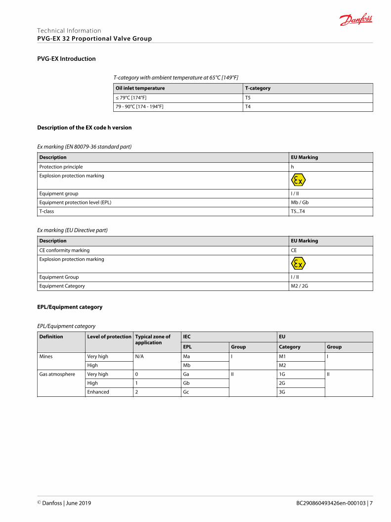
T-category with ambient temperature at 65°C [149°F]
Oil inlet temperature T-category
≤ 79°C [174°F] T5
79 - 90°C [174 - 194°F] T4
Description of the EX code h version
Ex marking (EN 80079-36 standard part)
Description EU Marking
Protection principle h
Explosion protection marking
Equipment group I / II
Equipment protection level (EPL) Mb / Gb
T-class T5...T4
Ex marking (EU Directive part)
Description EU Marking
CE conformity marking CE
Explosion protection marking
Equipment Group I / II
Equipment Category M2 / 2G
EPL/Equipment category
EPL/Equipment category
Definition Level of protection Typical zone ofapplication
IEC EU
EPL Group Category Group
Mines Very high N/A Ma I M1 I
High Mb M2
Gas atmosphere Very high 0 Ga II 1G II
High 1 Gb 2G
Enhanced 2 Gc 3G
Technical InformationPVG-EX 32 Proportional Valve Group
PVG-EX Introduction
© Danfoss | June 2019 BC290860493426en-000103 | 7

General description
PVG 32 is a hydraulic load sensing (LS) valve designed to give maximum flexibility. From a simple loadsensing directional valve, to an advanced electrically controlled load-independent proportional valve.
The PVG 32 modular system makes it possible to build up a valve group to meet the different functionalrequirements precisely.
The compact external dimensions of the valve remain unchanged whatever combination is specified.
The PVG 32 interfaces to other valve families like PVG 16, PVG 100 or PVG 120 enabling all machinefunctions being controlled from one single valve stack.
Features
Features of the PVG 32 include:• Load-independent flow control:
‒ Oil flow to an individual function is independent of the load pressure of this function
‒ Oil flow to one function is independent of the load pressure of other functions• Good regulation characteristics• Energy-saving• Up to 12 basic modules per valve group• Several types of connection threads• Low weight• Compact design and installation
Inlets
The inlets include:• Built-in pressure relief valve• Pressure gauge connection• Versions for different pump types
‒ Open Center systems with fixed displacement pumps
‒ Closed Center systems with variable displacement pumps• Integrated pilot oil supply
Work section housing
Our work section housing includes:• Interchangeable spools• Pressure gauge connection• Versions for different application needs
‒ Built-in compensator for load independent flow
‒ Built-in load holding check valve in P-channel
‒ Integrated shock/suction valve
‒ Integrated local pressure relief valve
Technical InformationPVG-EX 32 Proportional Valve Group
General information
8 | © Danfoss | June 2019 BC290860493426en-000103

Actuation methods
Our actuation methods include:• Manual control with lever• Manual with friction detent• Hydraulic• Electro-hydraulic
‒ ON/OFF control
‒ Ratiometric proportional
‒ CANbus proportional
‒ PWM proportional
Technical InformationPVG-EX 32 Proportional Valve Group
General information
© Danfoss | June 2019 BC290860493426en-000103 | 9

Sectional view
1. Pressure relief valve 11. Main spool
2. Pressure reduction valve for pilot oil supply 12. LS pressure limiting valve
3. Pressure gauge connection 13. Shock and suction valve, PVLP
4. Plug, open center 14. Pressure compensator
5. Orifice, closed center 15. LS connection, port A
6. Pressure adjustment spool 16. LS connection, port B
7. Plug, closed center 17. Suction valve, PVLA
8. LS connection 18. Load drop check valve
9. LS signal 19. Pilot oil supply for PVE
10. Shuttle valve 20. Maximum oil flow adjustment screws for A/B ports
Technical InformationPVG-EX 32 Proportional Valve Group
General information
10 | © Danfoss | June 2019 BC290860493426en-000103

PVG-EX modules overview
PVG-EX 32 modules exploded view
PVG modules navigation
• PVP Inlet Modules on page 12• PVB Basic Modules on page 38• PVBS Main Spools on page 75• PVSKM Full Flow Cut Off Modules on page 126• PVAS Stay Bolts on page 131
Technical InformationPVG-EX 32 Proportional Valve Group
General information
© Danfoss | June 2019 BC290860493426en-000103 | 11

The PVG-EX 32 PVP inlet modules, also referred to as pump side modules, act as an interface between thePVG-EX 32 proportional valve group and the hydraulic pump and tank reservoir.
PVP Inlet Module PVP inlet module dimensions
112.
5 [4
.43]
110 [4.33]
95 [3.74] 23 [0.9]
48 [1.89]
Weight: 3.1 kg [6.9 lb]
Fixed displacement pump symbol Variable displacement pump symbol
The PVP inlet module variants are based on a generic platform with a selection of additional features,enabling you to tailor the PVP to suit the demands of any hydraulic system:• Open Center PVP on page 13 (for fixed displacement pumps)
• Open Center PVP with PPRV on page 16 (for fixed displacement pumps)
• Open center PVP with HPCO and PVE PPRV on page 19 (for fixed displacement pumps)
• Closed Center PVP on page 22 (for variable displacement pumps)
• Closed Center PVP with PPRV on page 24 (for variable displacement pumps)
• Closed center PVPV with PPRV on page 27 (for variable displacement pumps)
• Closed center PVPVM with PPRV on page 29 (for variable displacement pumps)
• Open/Closed center PVP with PPRV on page 31
• Open/Closed center PVPM on page 34
Technical InformationPVG-EX 32 Proportional Valve Group
PVP Inlet Modules
12 | © Danfoss | June 2019 BC290860493426en-000103

Open Center PVP
The basic Open Center PVP inlet module is intended for use with fixed displacement pumps inapplications, where a valve group with mechanically controlled work sections is desired, or where thepilot pressure to the valve group is supplied externally.
The Open Center PVP features:• Integrated LS pressure relief valve
• Threaded ports for P/T/LS and M measuring gauge
• Optional T0 facility and external T0 port
All modules can be manually activated with the PVM actuation.
Open center PVP schematic
LS
T
P
M
Technical specification for PVP
Max. P-port continuous Max. P-port intermittent Max. T-port static/dynamic
Max. rated flow
350 [5076 psi] 400 bar [5800 psi] 25/40 bar [365/580 psi] 140 l/min [37 US gal/min]
Technical specification
Parameter Minimum Recommended range Maximum
Fluid temperature -30°C [-22°F] 30 to 60°C [86 to 140°F] 90° [194°F]
Fluid viscosity 4 mm2/s [39 SUS] 12 to 75 mm2/s [65 to 347 SUS] 460 mm2/s [2128 SUS]
Fluid cleanliness 23/19/16 (according to ISO 4406)
Operating temperature Ambient: -30 to 60°C [-22 to 140°F]
Technical InformationPVG-EX 32 Proportional Valve Group
PVP Inlet Modules
© Danfoss | June 2019 BC290860493426en-000103 | 13
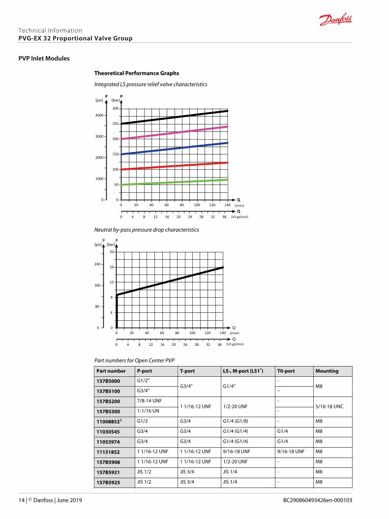
Theoretical Performance Graphs
Integrated LS pressure relief valve characteristics
[l/min]
[US gal/min]
200
150
100
50
20 40 60 80 100 120 140Q
300
250
PP
2000
1000
0 00
204 8 2824 32 3612 160
3000
4000
[psi]
Q
(bar)
Neutral by-pass pressure drop characteristics
(l/min)
[US gal/min]
20
20 40 60 80 100 120 140
16
12
8
4
160
80
0 00
240
[psi] (bar)
4 8 12 16 20 24 28 32 360
Part numbers for Open Center PVP
Part number P-port T-port LS-, M-port (LS1*) T0-port Mounting
157B5000 G1/2”G3/4” G1/4”
-M8
157B5100 G3/4” –
157B5200 7/8-14 UNF1 1/16-12 UNF 1/2-20 UNF
-5/16-18 UNC
157B5300 1-1/16 UN -
110088521 G1/2 G3/4 G1/4 (G1/8) - M8
11030545 G3/4 G3/4 G1/4 (G1/4) G1/4 M8
11053974 G3/4 G3/4 G1/4 (G1/4) G1/4 M8
11151852 1 1/16-12 UNF 1 1/16-12 UNF 9/16-18 UNF 9/16-18 UNF M8
157B5908 1 1/16-12 UNF 1 1/16-12 UNF 1/2-20 UNF - M8
157B5921 JIS 1/2 JIS 3/4 JIS 1/4 - M8
157B5925 JIS 1/2 JIS 3/4 JIS 1/4 - M8
Technical InformationPVG-EX 32 Proportional Valve Group
PVP Inlet Modules
14 | © Danfoss | June 2019 BC290860493426en-000103

Part numbers for Open Center PVP (continued)
Part number P-port T-port LS-, M-port (LS1*) T0-port Mounting
157B5945 G1/2 G3/4 G1/4 (G1/8) - M8
157B59902 1 1/16-12 UNF 1 1/16-12 UNF - - M8
* LS1 is an extra LS-port.1 Dampened LS response2 No relief valve
Technical InformationPVG-EX 32 Proportional Valve Group
PVP Inlet Modules
© Danfoss | June 2019 BC290860493426en-000103 | 15

Open Center PVP with PPRV
The Open Center PVP inlet with integrated pilot pressure reduction valve (PPRV) is intended for use withfixed displacement pumps in applications, where a valve group with electro-hydraulically or hydraulicallycontrolled work sections is desired (PVE or PVH/PVHC).
The Open Center PVP with PPRV features:• Integrated LS pressure relief valve
• Threaded ports for P/T/LS and M measuring gauge
• Integrated pilot pressure reducing valve (PPRV) for PVE or PVH/PVHC
• Optional T0 facility and external T0 port
• Optional external pilot pressure port (Pp)
All modules can be manually activated with the PVM actuation.
Open center PVP with PPRV schematic
Pp
LS
T
P
M
Technical specification for PVP
Max. P-port continuous Max. P-port intermittent Max. T-port static/dynamic
Max. rated flow
350 [5076 psi] 400 bar [5800 psi] 25/40 bar [365/580 psi] 140 l/min [37 US gal/min]
Technical specification
Parameter Minimum Recommended range Maximum
Fluid temperature -30°C [-22°F] 30 to 60°C [86 to 140°F] 90° [194°F]
Fluid viscosity 4 mm2/s [39 SUS] 12 to 75 mm2/s [65 to 347 SUS] 460 mm2/s [2128 SUS]
Fluid cleanliness 23/19/16 (according to ISO 4406)
Operating temperature Ambient: -30 to 60°C [-22 to 140°F]
Technical InformationPVG-EX 32 Proportional Valve Group
PVP Inlet Modules
16 | © Danfoss | June 2019 BC290860493426en-000103

Theoretical Performance Graphs
Integrated LS pressure relief valve characteristics
[l/min]
[US gal/min]
200
150
100
50
20 40 60 80 100 120 140Q
300
250
PP
2000
1000
0 00
204 8 2824 32 3612 160
3000
4000
[psi]
Q
(bar)
Neutral by-pass pressure drop characteristics
(l/min)
[US gal/min]
20
20 40 60 80 100 120 140
16
12
8
4
160
80
0 00
240
[psi] (bar)
4 8 12 16 20 24 28 32 360
Pilot pressure reduction valve characteristics
(l/min)
[US gal/min]
20
10 20 30 40 50
16
18
12
14
10
8
4
6
2
100
20
60
0 00
220
140
180
260
[psi] (bar)
6 122 4 8 100
Technical InformationPVG-EX 32 Proportional Valve Group
PVP Inlet Modules
© Danfoss | June 2019 BC290860493426en-000103 | 17

Part numbers for Open Center PVP with PPRV
Part number Actuation P-port T-port LS-port M-port Pp-port T0-port Mounting
110088491 PVE G3/4” G3/4” G1/4” G1/4” - - M8
110088511 PVH/PVHC G3/4” G3/4” G1/4” G1/4” G1/4” - M8
11072195 PVE M27x2 M27x2 M14x1.5 M14x1.5 - M14x1.5 M8
157B5010 PVE G1/2” G3/4” G1/4” G1/4” - - M8
157B5110 PVE G3/4” G3/4” G1/4” G1/4” - - M8
157B5130 PVE G3/4” G3/4” G1/4” G1/4” G1/4” G1/4” M8
157B5180 PVE G3/4” G3/4” G1/4” G1/4” G1/4” - M8
157B5190 PVH/PVHC G3/4” G3/4” G1/4” G1/4” G1/4” - M8
157B5210 PVE 7/8-14 UNF 1 1/16-12 UNF 1/2-20 UNF 1/2-20 UNF - - 5/16-18 UNC
157B5310 PVE 1 1/16-12 UNF 1 1/16-12 UNF 1/2-20 UNF 1/2-20 UNF - - 5/16-18 UNC
157B5312 PVE 1 1/16-12 UNF 1 1/16-12 UNF 1/2-20 UNF 1/2-20 UNF - - 5/16-18 UNC
157B5330 PVE 1 1/16-12 UNF 1 1/16-12 UNF 1/2-20 UNF 1/2-20 UNF 1/2-20 UNF - 5/16-18 UNC
157B5380 PVE 1 1/16-12 UNF 1 1/16-12 UNF 9/16-18 UNF 9/16-18 UNF 9/16-18 UNF - 5/16-18 UNC
157B5390 PVH/PVHC 1 1/16-12 UNF 1 1/16-12 UNF 9/16-18 UNF 9/16-18 UNF 9/16-18 UNF - 5/16-18 UNC
11101194 PVE M22x1.5M16x1.5 (P2)
M22x1.5 M12x1.5 M10x1 - M16x1.5 M8
110133171 PVE G3/4 G3/4 G1/4 G1/4 G1/4 G1/4 M8
11020964 PVE 1 1/16-12 UNF 1 1/16-12 UNF 1/2-20 UNF 1/2-20 UNF - - M8
110875901 PVH/PVHC G3/4 G3/4 G1/4 G1/4 G1/4 - M8
11090453 PVE JIS 3/4 JIS 3/4 JIS 1/4 JIS 1/4 JIS 1/4 JIS 1/4 M8
111194292 PVE G3/4 G3/4 G1/4 G1/4 G1/4 - M8
11124966 PVH/PVHC G3/4 G3/4 G1/4 G1/4 G1/4 - M8
111309412 PVE 1 1/16-12 UNF 1 1/16-12 UNF 9/16-18 UNF 9/16-18 UNF 9/16-18 UNF - 5/16-18 UNC
11196947 PVE G3/4 G3/4 G1/4 G1/4 - G1/4 M8
11225941 PVE 1 1/16-12 UNF 1 1/16-12 UNF 9/16-18 UNF 9/16-18 UNF 9/16-18 UNF 9/16-18UNF
5/16-18 UNC
157B51353 PVE G3/4 G3/4 G1/4 G1/4 G1/4 G1/4 M8
157B59042 PVE G3/4 G3/4 G1/4 G1/4 G1/4 - M8
157B5923 PVE JIS 1/2 JIS 3/4 JIS 1/4 JIS 1/4 - - M8
157B5926 PVE JIS 3/4 JIS 3/4 JIS 1/4 JIS 1/4 - - M8
157B5934 PVE G3/4 G3/4 G1/4 G1/4 - - M8
157B59432 PVH/PVHC G3/4 G3/4 G1/4 G1/4 G1/4 - M8
157B5954 PVE G3/4 G3/4 G1/4 G1/4 G1/4 - M8
157B5960 PVE 1 1/16-12 UNF 1 1/16-12 UNF 9/16-18 UNF 9/16-18 UNF - 9/16-18UNF
5/16-18 UNF
157B59771,4 PVE G3/4 G3/4 G1/4 G1/4 - - M8
11101194 PVE M22 x 1.5 M22 x 1.5 M12 x 1.5 M10 x 1 - M16 x 1.5 M8
1 Dampened LS response2 Pressure adjustment spool with check valve3 Internal T0 connection4 Low flow pressure adjustment spool
Technical InformationPVG-EX 32 Proportional Valve Group
PVP Inlet Modules
18 | © Danfoss | June 2019 BC290860493426en-000103

Open center PVP with HPCO and PVE PPRV
The Open Center PVP inlet with integrated High Pressure Carry Over (HPCO) functionality is intended foruse with fixed displacement pumps in applications where one pump supply for multiple hydraulicsubsystems is desired.
The integrated HPCO functionality guides the excess flow of the PVG-EX 32 valve group to the externalhydraulic subsystem(s), giving priority to the PVG-EX 32 work functions.
The Open Center PVP with HPCO and PVE PPRV features:• Integrated LS pressure relief valve
• Threaded ports for P/T/LS/HPCO and M measuring gauge
• Integrated pilot pressure reducing valve (PPRV) for PVE
• Optional T0 facility and external T0 port
• Optional external pilot pressure port (Pp)
Only applicable with PVST end plates with separate T-port due to blocked T-lines for HPCO functionality.
Open Center PVP with HPCO, PVE PPRV schematic
LS
HPCO
P
M T0
Technical specification for PVP
Max. P-port continuous Max. P-port intermittent Max. T-port static/dynamic
Max. rated flow
350 [5076 psi] 400 bar [5800 psi] 25/40 bar [365/580 psi] 140 l/min [37 US gal/min]
Technical specification
Parameter Minimum Recommended range Maximum
Fluid temperature -30°C [-22°F] 30 to 60°C [86 to 140°F] 90° [194°F]
Fluid viscosity 4 mm2/s [39 SUS] 12 to 75 mm2/s [65 to 347 SUS] 460 mm2/s [2128 SUS]
Fluid cleanliness 23/19/16 (according to ISO 4406)
Operating temperature Ambient: -30 to 60°C [-22 to 140°F]
Technical InformationPVG-EX 32 Proportional Valve Group
PVP Inlet Modules
© Danfoss | June 2019 BC290860493426en-000103 | 19

Theoretical Performance Graphs
Integrated LS pressure relief valve characteristics
[l/min]
[US gal/min]
200
150
100
50
20 40 60 80 100 120 140Q
300
250
PP
2000
1000
0 00
204 8 2824 32 3612 160
3000
4000
[psi]
Q
(bar)
Neutral by-pass pressure drop characteristics
(l/min)
[US gal/min]
20
20 40 60 80 100 120 140
16
12
8
4
160
80
0 00
240
[psi] (bar)
4 8 12 16 20 24 28 32 360
Pilot pressure reduction valve characteristics
(l/min)
[US gal/min]
20
10 20 30 40 50
16
18
12
14
10
8
4
6
2
100
20
60
0 00
220
140
180
260
[psi] (bar)
6 122 4 8 100
Technical InformationPVG-EX 32 Proportional Valve Group
PVP Inlet Modules
20 | © Danfoss | June 2019 BC290860493426en-000103
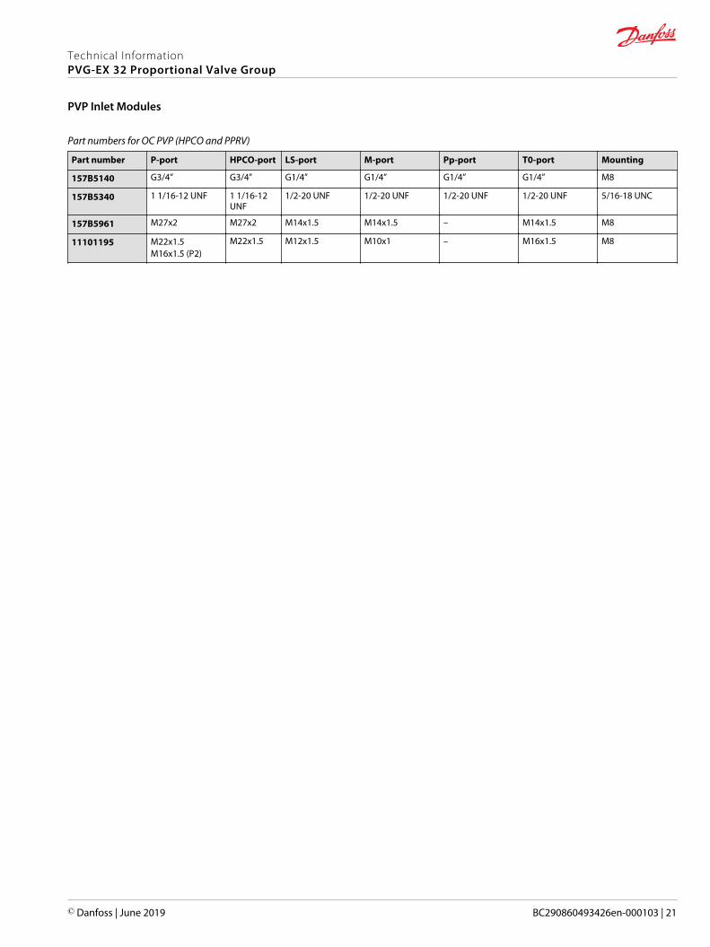
Part numbers for OC PVP (HPCO and PPRV)
Part number P-port HPCO-port LS-port M-port Pp-port T0-port Mounting
157B5140 G3/4” G3/4" G1/4” G1/4” G1/4” G1/4” M8
157B5340 1 1/16-12 UNF 1 1/16-12UNF
1/2-20 UNF 1/2-20 UNF 1/2-20 UNF 1/2-20 UNF 5/16-18 UNC
157B5961 M27x2 M27x2 M14x1.5 M14x1.5 – M14x1.5 M8
11101195 M22x1.5M16x1.5 (P2)
M22x1.5 M12x1.5 M10x1 – M16x1.5 M8
Technical InformationPVG-EX 32 Proportional Valve Group
PVP Inlet Modules
© Danfoss | June 2019 BC290860493426en-000103 | 21

Closed Center PVP
The basic Closed Center PVP inlet is intended for use with variable displacement pumps in applicationswhere a valve group with mechanically controlled work sections is desired, or where the pilot pressure tothe valve group is supplied externally.
The Closed Center PVP features:• Integrated LS pressure relief valve
• Threaded ports for P/T/LS and M measuring gauge
• Optional T0 facility and external T0 port
Closed center PVP schematic
LS
T
P
M
Technical specification for PVP
Max. P-port continuous Max. P-port intermittent Max. T-port static/dynamic
Max. rated flow
350 [5076 psi] 400 bar [5800 psi] 25/40 bar [365/580 psi] 140 l/min [37 US gal/min]
Technical specification
Parameter Minimum Recommended range Maximum
Fluid temperature -30°C [-22°F] 30 to 60°C [86 to 140°F] 90° [194°F]
Fluid viscosity 4 mm2/s [39 SUS] 12 to 75 mm2/s [65 to 347 SUS] 460 mm2/s [2128 SUS]
Fluid cleanliness 23/19/16 (according to ISO 4406)
Operating temperature Ambient: -30 to 60°C [-22 to 140°F]
Technical InformationPVG-EX 32 Proportional Valve Group
PVP Inlet Modules
22 | © Danfoss | June 2019 BC290860493426en-000103
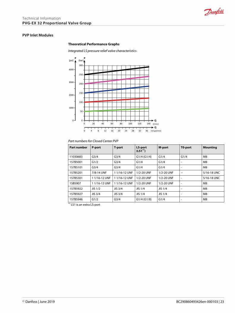
Theoretical Performance Graphs
Integrated LS pressure relief valve characteristics
[l/min]
[US gal/min]
200
150
100
50
20 40 60 80 100 120 140Q
300
250
PP
2000
1000
0 00
204 8 2824 32 3612 160
3000
4000
[psi]
Q
(bar)
Part numbers for Closed Center PVP
Part number P-port T-port LS-port(LS1**)
M-port T0-port Mounting
11030683 G3/4 G3/4 G1/4 (G1/4) G1/4 G1/4 M8
157B5001 G1/2 G3/4 G1/4 G1/4 - M8
157B5101 G3/4 G3/4 G1/4 G1/4 - M8
157B5201 7/8-14 UNF 1 1/16-12 UNF 1/2-20 UNF 1/2-20 UNF -- 5/16-18 UNC
157B5301 1 1/16-12 UNF 1 1/16-12 UNF 1/2-20 UNF 1/2-20 UNF - 5/16-18 UNC
15B5907 1 1/16-12 UNF 1 1/16-12 UNF 1/2-20 UNF 1/2-20 UNF - M8
157B5922 JIS 1/2 JIS 3/4 JIS 1/4 JIS 1/4 - M8
157B5927 JIS 3/4 JIS 3/4 JIS 1/4 JIS 1/4 - M8
157B5946 G1/2 G3/4 G1/4 (G1/8) G1/4 - M8** LS1 is an extra LS-port
Technical InformationPVG-EX 32 Proportional Valve Group
PVP Inlet Modules
© Danfoss | June 2019 BC290860493426en-000103 | 23

Closed Center PVP with PPRV
The Closed Center PVP inlet with integrated pilot pressure reduction valve (PPRV) is intended for use withvariable displacement pumps in applications where a valve group with electro-hydraulic or hydraulicallycontrolled work sections is desired.
The Closed Center PVP with PPRV features:• Integrated LS pressure relief valve
• Threaded ports for P/T/LS and M measuring gauge
• Integrated pilot pressure reducing valve (PPRV) for PVE or PVH/PVHC
• Optional T0 facility and external T0 port
Closed center PVP with PPRV schematic
Pp
LS
T
P
M
Technical specification for PVP
Max. P-port continuous Max. P-port intermittent Max. T-port static/dynamic
Max. rated flow
350 [5076 psi] 400 bar [5800 psi] 25/40 bar [365/580 psi] 140 l/min [37 US gal/min]
Technical specification
Parameter Minimum Recommended range Maximum
Fluid temperature -30°C [-22°F] 30 to 60°C [86 to 140°F] 90° [194°F]
Fluid viscosity 4 mm2/s [39 SUS] 12 to 75 mm2/s [65 to 347 SUS] 460 mm2/s [2128 SUS]
Fluid cleanliness 23/19/16 (according to ISO 4406)
Operating temperature Ambient: -30 to 60°C [-22 to 140°F]
Technical InformationPVG-EX 32 Proportional Valve Group
PVP Inlet Modules
24 | © Danfoss | June 2019 BC290860493426en-000103
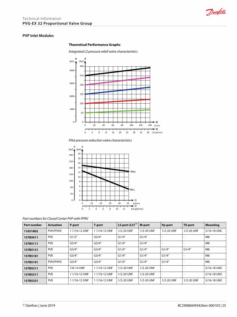
Theoretical Performance Graphs
Integrated LS pressure relief valve characteristics
[l/min]
[US gal/min]
200
150
100
50
20 40 60 80 100 120 140Q
300
250
PP
2000
1000
0 00
204 8 2824 32 3612 160
3000
4000
[psi]
Q
(bar)
Pilot pressure reduction valve characteristics
(l/min)
[US gal/min]
20
10 20 30 40 50
16
18
12
14
10
8
4
6
2
100
20
60
0 00
220
140
180
260
[psi] (bar)
6 122 4 8 100
Part numbers for Closed Center PVP with PPRV
Part number Actuation P-port T-port LS-port (LS1** M-port Pp-port T0-port Mounting
11051802 PVH/PVHC 1 1/16-12 UNF 1 1/16-12 UNF 1/2-20 UNF 1/2-20 UNF 1/2-20 UNF 1/2-20 UNF 5/16-18 UNC
157B5011 PVE G1/2” G3/4” G1/4” G1/4” - - M8
157B5111 PVE G3/4” G3/4” G1/4” G1/4” - - M8
157B5131 PVE G3/4” G3/4” G1/4” G1/4” G1/4” G1/4” M8
157B5181 PVE G3/4” G3/4” G1/4” G1/4” G1/4” - M8
157B5191 PVH/PVHC G3/4” G3/4” G1/4” G1/4” G1/4” - M8
157B5211 PVE 7/8-14 UNF 1 1/16-12 UNF 1/2-20 UNF 1/2-20 UNF - - 5/16-18 UNC
157B5311 PVE 1 1/16-12 UNF 1 1/16-12 UNF 1/2-20 UNF 1/2-20 UNF - - 5/16-18 UNC
157B5331 PVE 1 1/16-12 UNF 1 1/16-12 UNF 1/2-20 UNF 1/2-20 UNF 1/2-20 UNF 1/2-20 UNF 5/16-18 UNC
Technical InformationPVG-EX 32 Proportional Valve Group
PVP Inlet Modules
© Danfoss | June 2019 BC290860493426en-000103 | 25

Part numbers for Closed Center PVP with PPRV (continued)
Part number Actuation P-port T-port LS-port (LS1** M-port Pp-port T0-port Mounting
157B5381 PVE 1 1/16-12 UNF 1 1/16-12 UNF 9/16-18 UNF 9/16-18 UNF 9/16-18 UNF - 5/16-18 UNC
157B5391 PVH/PVHC 1 1/16-12 UNF 1 1/16-12 UNF 9/16-18 UNF 9/16-18 UNF 9/16-18 UNF - 5/16-18 UNC
** LS1 is an extra LS-port
All modules can be manually activated with the PVM actuation.
Closed center PVPV
The Closed Center PVPV inlet is intended for use with variable displacement pumps in applications wherea valve group with mechanical controlled work sections is desired.
The Closed center PVPV features:• Optional T0 facility and port• Threaded ports for P/T/LS and M measuring gauge• Optional additional threaded ports for P2, T2, and T02
PVPV Schematic
T
LS
P
M
Technical specification for PVP
Max. P-port continuous Max. P-port intermittent Max. T-port static/dynamic
Max. rated flow
350 [5076 psi] 400 bar [5800 psi] 25/40 bar [365/580 psi] 140 l/min [37 US gal/min]
Technical specification
Parameter Minimum Recommended range Maximum
Fluid temperature -30°C [-22°F] 30 to 60°C [86 to 140°F] 90° [194°F]
Fluid viscosity 4 mm2/s [39 SUS] 12 to 75 mm2/s [65 to 347 SUS] 460 mm2/s [2128 SUS]
Fluid cleanliness 23/19/16 (according to ISO 4406)
Operating temperature Ambient: -30 to 60°C [-22 to 140°F]
Part numbers for Closed Center PVPV
Part number P-port (P2) T-port (T2) LS-port M-port T0-port (T02) Mounting
11055758 M27x2.0(M27x2.0)
M27x2.0(M14x1.5)
M14x1.5 M14x1.5 M14x1.5(M14x1.5)
M8
11067570 M27x2.0 M33x2.0 M14x1.5 M14x1.5 - M8
Technical InformationPVG-EX 32 Proportional Valve Group
PVP Inlet Modules
26 | © Danfoss | June 2019 BC290860493426en-000103

Closed center PVPV with PPRV
The Closed Center PVPV inlet with integrated pilot pressure reduction valve (PPRV) is intended for usewith variable displacement pumps in applications where a valve group with electro-hydraulic orhydraulically controlled work sections is desired.
The Closed Center PVPV with PPRV features:• Optional shock/anti-cavitation valve facility (PVLP)
• Threaded ports for P/T/LS and M measuring gauge
• Integrated pilot pressure reducing valve (PPRV) for PVE or PVH/PVHC
Hydraulic schematic
T
LS
P
M
Technical specification for PVP
Max. P-port continuous Max. P-port intermittent Max. T-port static/dynamic
Max. rated flow
350 [5076 psi] 400 bar [5800 psi] 25/40 bar [365/580 psi] 140 l/min [37 US gal/min]
Technical specification
Parameter Minimum Recommended range Maximum
Fluid temperature -30°C [-22°F] 30 to 60°C [86 to 140°F] 90° [194°F]
Fluid viscosity 4 mm2/s [39 SUS] 12 to 75 mm2/s [65 to 347 SUS] 460 mm2/s [2128 SUS]
Fluid cleanliness 23/19/16 (according to ISO 4406)
Operating temperature Ambient: -30 to 60°C [-22 to 140°F]
Pilot pressure reduction valve characteristics
(l/min)
[US gal/min]
20
10 20 30 40 50
16
18
12
14
10
8
4
6
2
100
20
60
0 00
220
140
180
260
[psi] (bar)
6 122 4 8 100
Technical InformationPVG-EX 32 Proportional Valve Group
PVP Inlet Modules
© Danfoss | June 2019 BC290860493426en-000103 | 27

Part numbers for Closed Center PVPV with PPRV
Part number Actuator P-port T-port (T2) LS-port M-port Pp-port T0-port(T02)
Mounting PVLP
110123501
PVE
M27x2.0 M33x2.0 M14x1.5 M14x1.5 G1/4 - M8 -
11003806 M27x2.0 M27x2.0(M14x1.5)
M14x1.5 M14x1.5 G1/4 M14x1.5(M14x1.5)
M8 -
110088542 G1 G1 G1/4 G1/4 G1/4 - M8 Yes
11124107 1 5/16-12 1 1/16-12 9/16-18 9/16-18 G1/4 - M8 Yes
11196949 G1 G1 - - - - M8 Yes
157B5911 1 5/16-12 1 5/16-12 9/16-18 9/16-18 G1/4 - 5/16-18 -
157B5913 1 5/16-12 1 5/16-12 9/16-18 9/16-18 G1/4 - 5/16-18 Yes
157B5938 G1 G1 G1/4 G1/4 G1/4 - M8 -
157B5941 G1 G1 G1/4 G1/4 G1/4 - M8 Yes
157B59483 G1 G1 G1/4 G1/4 G1/4 - M8 Yes
157B59734 G1 G1 G1/4 G1/4 G1/4 - M8 Yes
157B5978 M27x2.0 M33x2.0 M14x1.5 M14x1.5 G1/4 - M8 -
11008856
PVH/PVHC
G1 G1 G1/4 G1/4 G1/4 - M8 Yes
11051803 1 5/16-12 1 5/16-12 9/16-18 9/16-18 G1/4 - 5/16-18 Yes
157B5916 1 5/16-12 1 5/16-12 9/16-18 9/16-18 G1/4 - 5/16-18 -
157B5963 1 1/16-12 1 1/16-12 7/16-20 - M18x1.5 9/16-18 M8 -1 No LS-orifice2 Internal T0 connection3 0.4 mm hole in the pilot reduction cone (standard 0.8 mm)4 HPCO-facility
All modules can be manually activated with the PVM actuation.
Technical InformationPVG-EX 32 Proportional Valve Group
PVP Inlet Modules
28 | © Danfoss | June 2019 BC290860493426en-000103

Closed center PVPVM with PPRV
The Closed Center PVPVM mid-inlet module with integrated pilot pressure reduction valve (PPRV) isintended for use with variable displacement pumps in applications where a valve group with electro-hydraulic or hydraulically controlled work sections is desired.
Using a PVPVM module in a valve group requires a 180° degree rotation of the PVG work sections on oneside.
The Closed Center PVPVM with PPRV features:• Optional shock/anti-cavitation valve facility (PVLP)
• Threaded ports for P/T/LS and M measuring gauge
• Integrated pilot pressure reducing valve (PPRV) for PVE or PVH/PVHC
Hydraulic schematic
T
LS
P
M
Technical specification for PVP
Max. P-port continuous Max. P-port intermittent Max. T-port static/dynamic
Max. rated flow
350 [5076 psi] 400 bar [5800 psi] 25/40 bar [365/580 psi] 140 l/min [37 US gal/min]
Technical specification
Parameter Minimum Recommended range Maximum
Fluid temperature -30°C [-22°F] 30 to 60°C [86 to 140°F] 90° [194°F]
Fluid viscosity 4 mm2/s [39 SUS] 12 to 75 mm2/s [65 to 347 SUS] 460 mm2/s [2128 SUS]
Fluid cleanliness 23/19/16 (according to ISO 4406)
Operating temperature Ambient: -30 to 60°C [-22 to 140°F]
Pilot pressure reduction valve characteristics
(l/min)
[US gal/min]
20
10 20 30 40 50
16
18
12
14
10
8
4
6
2
100
20
60
0 00
220
140
180
260
[psi] (bar)
6 122 4 8 100
Technical InformationPVG-EX 32 Proportional Valve Group
PVP Inlet Modules
© Danfoss | June 2019 BC290860493426en-000103 | 29

Part numbers for Closed Center PVPVM with PPRV
Part number Actuator P-port T-port LS-port M-port Pp-port Mounting PVLP
157B5914
PVE
1 5/16-12UNF
1 5/16-12UNF
9/16-18 UNF 9/16-18 UNF G1/4 5/16-18 UNC Yes
157B5937 G1 G1 G1/4 G1/4 G1/4 M8 -
157B5940 G1 G1 G1/4 G1/4 G1/4 M8 Yes
11083156
PVH/PVHC
1 1/16-12UNF
1 1/16-12UNF
9/16-18 UNF 9/16-18 UNF G1/4 5/16-18 UNC Yes
157B5912 1 5/16-12UNF
1 5/16-12UNF
9/16-18 UNF 9/16-18 UNF G1/4 5/16-18 UNC -
157B5986 G1 G1 G1/4 G1/4 G1/4 M8 Yes
All modules can be manually activated with the PVM actuation.
Technical InformationPVG-EX 32 Proportional Valve Group
PVP Inlet Modules
30 | © Danfoss | June 2019 BC290860493426en-000103

Open/Closed center PVP with PPRV
The Open Center/Closed Center PVP with integrated pilot pressure reduction valve (PPRV) is intended foruse with fixed or variable displacement pumps in applications where the application manufacturer doesnot determine the pump type.
The modules allow an easy switch between Open Center and Closed Center configuration by means of anexternal hexagon selector key. Variants also feature an LS boost functionality, increasing the LS pressureto the pump LS regulator with a constant 6 bar, compensating for potential LS bleed-off and leakage.
The Open/closed center PVPV with PPRV features:• Integrated OC/CC selector
• Integrated LS pressure relief valve
• Threaded ports for P/T/LS and M measuring gauge
• Integrated pilot pressure reducing valve (PPRV) for PVE or PVH/PVHC
• Optional LS boost functionality
Hydraulic schematic
LS
T
P
M
OC CC
Technical specification for PVP
Max. P-port continuous Max. P-port intermittent Max. T-port static/dynamic
Max. rated flow
350 [5076 psi] 400 bar [5800 psi] 25/40 bar [365/580 psi] 140 l/min [37 US gal/min]
Technical specification
Parameter Minimum Recommended range Maximum
Fluid temperature -30°C [-22°F] 30 to 60°C [86 to 140°F] 90° [194°F]
Fluid viscosity 4 mm2/s [39 SUS] 12 to 75 mm2/s [65 to 347 SUS] 460 mm2/s [2128 SUS]
Fluid cleanliness 23/19/16 (according to ISO 4406)
Operating temperature Ambient: -30 to 60°C [-22 to 140°F]
Technical InformationPVG-EX 32 Proportional Valve Group
PVP Inlet Modules
© Danfoss | June 2019 BC290860493426en-000103 | 31

Theoretical Performance Graphs
Integrated LS pressure relief valve characteristics
[l/min]
[US gal/min]
200
150
100
50
20 40 60 80 100 120 140Q
300
250
PP
2000
1000
0 00
204 8 2824 32 3612 160
3000
4000
[psi]
Q
(bar)
Neutral by-pass pressure drop characteristics
(l/min)
[US gal/min]
20
20 40 60 80 100 120 140
16
12
8
4
160
80
0 00
240
[psi] (bar)
4 8 12 16 20 24 28 32 360
Pilot pressure reduction valve characteristics
(l/min)
[US gal/min]
20
10 20 30 40 50
16
18
12
14
10
8
4
6
2
100
20
60
0 00
220
140
180
260
[psi] (bar)
6 122 4 8 100
Technical InformationPVG-EX 32 Proportional Valve Group
PVP Inlet Modules
32 | © Danfoss | June 2019 BC290860493426en-000103

Part numbers for Open/Closed Center PVP with PPRV
Part number Actuation P-port T-port LS-port (LS1**) M-port T0-port Mounting LS Boost
11093273 PVE G3/4 G3/4 - G1/4 - M8 Yes
11119094 PVE G3/4 G3/4 - G1/4 - M8 -
11119095 PVE 1 1/16-12 UNF 1 1/16-12 UNF 1/2-20 UNF 1/2-20 UNF - M8 -
11131344 PVH/PVHC G3/4 G3/4 - G1/4 - M8 Yes
111686081 PVE G3/4 G3/4 - G1/4 - M8 Yes** LS1 is an extra LS-port1 Dampened LS response
All modules can be manually activated with the PVM actuation.
Technical InformationPVG-EX 32 Proportional Valve Group
PVP Inlet Modules
© Danfoss | June 2019 BC290860493426en-000103 | 33

Open/Closed center PVPM
The Open Center/Closed Center PVPM mid-inlet acts as a simple manifold and is intended for use withfixed or variable displacement pumps. The PVPM features no logic other than a PVLP shock/anti-cavitation valve facility for pressure peak protection and anti-cavitation prevention.
The PVPM module must be configured together with an Open Center PVP module for fixeddisplacement pumps and for variable displacement pumps can be configured together with a PVSIstart plate or a Closed Center PVP/PVPV module.
The Open center/closed center PVPM features:• Integrated shock/anti-cavitation valve facility (PVLP)
• Threaded ports for P/T
• Pilot pressure and T0 lines through module
Hydraulic schematic
T
P
Technical specification for PVP
Max. P-port continuous Max. P-port intermittent Max. T-port static/dynamic
Max. rated flow
350 [5076 psi] 400 bar [5800 psi] 25/40 bar [365/580 psi] 140 l/min [37 US gal/min]
Technical specification
Parameter Minimum Recommended range Maximum
Fluid temperature -30°C [-22°F] 30 to 60°C [86 to 140°F] 90° [194°F]
Fluid viscosity 4 mm2/s [39 SUS] 12 to 75 mm2/s [65 to 347 SUS] 460 mm2/s [2128 SUS]
Fluid cleanliness 23/19/16 (according to ISO 4406)
Operating temperature Ambient: -30 to 60°C [-22 to 140°F]
Part numbers for Open Center/Closed Center PVPM
Part number P-, T-port Mounting PVLP
11093682 1 5/16-12 UN 5/16-18 UNC Yes
11093684 G1” M8 Yes
Technical InformationPVG-EX 32 Proportional Valve Group
PVP Inlet Modules
34 | © Danfoss | June 2019 BC290860493426en-000103

The generic PVP inlet module accessory platform includes the PVPX Electrical LS pressure unloadingvalve, External pilot pressure adapters PVPC with or without check valve for all Open Center PVP withPPRV.• PVPC without Check Valve on page 36
• PVPC with Check Valve on page 37
Technical InformationPVG-EX 32 Proportional Valve Group
PVP Inlet Module Accessories
© Danfoss | June 2019 BC290860493426en-000103 | 35

PVPC without Check Valve
The PVPC external pilot pressure adapter without check valve is an accessory in the M-port available forPVP inlet modules with integrated pilot pressure reduction valve (PPRV).
The PVPC without check valve cuts off the integrated PPRV to the PVE or PVH/PVHC in the valve groupand enables an external pilot pressure supply through the PVPC adapter.
PVPC without Check Valve
PVP with PVPC without check valve schematic
LS
T
P
M
Pp
One application example for the PVPC without check valve is where it is a wanted feature to supply thevalve group with oil from a manually operated emergency pump without directing oil flow to the PPRV.
When the main pump is running in its normal operation mode, the oil is directed through the PVPCadapter via the PPRV to the PVE electrical actuators.
When the main pump flow fails, the external shuttle valve ensures that the oil flow from the manuallyoperated emergency pump is used to pilot open the over-center valve and lower the load. The load isonly possible to lower when using the mechanical operating lever of the PVG work sections.
Part numbers for Open Center/Closed Center PVPM
Part number 157B5400 158X1000
Thread G1/2” 1/2-20 UNF
Technical InformationPVG-EX 32 Proportional Valve Group
PVP Inlet Module Accessories
36 | © Danfoss | June 2019 BC290860493426en-000103

PVPC with Check Valve
The PVPC external pilot pressure adapter with check valve is an accessory in the M-port available for PVPinlet modules with integrated pilot pressure reduction valve (PPRV).
The PVPC with check valve enables an external pilot pressure supply through the PVPC adapter and thePPRV, while also allowing the main pump to supply the PPRV through the P-gallery as a standard OpenCenter PVP with PPRV.
PVPC with Check Valve
PVP with PVPC with check valve schematic
LS
T
P
M
Pp
One application example for the PVPC with check valve is where it is a wanted feature to operate thevalve group by means of the PVE electrical actuators without pump flow.
When the external solenoid valve is opened, oil from the pressure side of the cylinder is fed via the PVPCthrough the PPRV to act as the pilot supply for the PVE electrical actuators. This means that it is possibleto lower a load by means of the PVE electrical actuators without starting the pump.
The built-in check valve prevents the oil from flowing via the pressure adjustment spool to tank. With thepump functioning normally the external solenoid valve is closed to ensure that the load is not lowereddue to the pilot supply oil flow requirement of approximately 1 l/min [0.25 US gal/min].
With a Closed Center PVP the external pilot oil supply can be connected to the pressure gaugeconnection without the use of a PVPC plug.
Part numbers for Open Center/Closed Center PVPM
Part number 157B5600 157B5700
Thread G1/2” 1/2-20 UNF
Technical InformationPVG-EX 32 Proportional Valve Group
PVP Inlet Module Accessories
© Danfoss | June 2019 BC290860493426en-000103 | 37

The PVG-EX 32 PVB basic modules, also referred to as work sections, are the interface between the PVG-EX 32 proportional valve group and the work function such as a cylinder or a motor.
PVB Basic Module PVB 32 dimensions
114
[4.4
9]
109
[4.2
9]
110 [4.33]
22.5 [0.89]
48 [1.89]
49 [1
.93]
Weight: 3.05 kg [6.73 lb]
Uncompensated PVB schematic symbol
P
Compensated PVB schematic symbol
P
The PVB basic module variants are based on a generic platform with a selection of additional features,enabling you to tailor the PVB to suit the demands of any hydraulic system. The generic PVB basicmodule platform includes the following main variants:• Uncompensated PVB on page 39
• Uncompensated PVB with load drop check valve on page 42
• Uncompensated PVBZ with POC on page 45
• Compensated PVB on page 46
• Dampened Compensated PVB on page 49
• Dampened compensated PVB with LS A/B on page 52
• Compensated PVB with LS A/B on page 55
• Compensated high flow PVB on page 59
• Compensated high flow PVB with LS A/B on page 62
• Compensated PVBZ with POC on page 66
• Compensated high flow PVBZ with POC on page 68
• Compensated high flow PVBZ with POC and manifold interface on page 70
Technical InformationPVG-EX 32 Proportional Valve Group
PVB Basic Modules
38 | © Danfoss | June 2019 BC290860493426en-000103
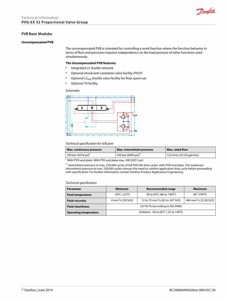
Uncompensated PVB
The uncompensated PVB is intended for controlling a work function where the function behavior interms of flow and pressures requires independence on the load pressure of other functions usedsimultaneously.
The Uncompensated PVB features:• Integrated LS shuttle network• Optional shock/anti-cavitation valve facility (PVLP)• Optional LSA/B shuttle valve facility for float spool use• Optional T0 facility
Schematic
A
B
1 0 2
Technical specification for A/B-port
Max. continuous pressure Max. intermittent pressure Max. rated flow
350 bar [5076 psi]* 420 bar [6090 psi]** 125 l/min [33 US gal/min]* With PVSI end plate. With PVS end plate max. 300 [4351 psi]** Intermittent pressure at max. 250,000 cycles of full PVG life time cycles, with PVSI end plate. The maximumintermittent pressure at max. 250,000 cycles stresses the need to confirm application duty cycle before proceedingwith specification. For further information contact Danfoss Product Application Engineering.
Technical specification
Parameter Minimum Recommended range Maximum
Fluid temperature -30°C [-22°F] 30 to 60°C [86 to 140°F] 90° [194°F]
Fluid viscosity 4 mm2/s [39 SUS] 12 to 75 mm2/s [65 to 347 SUS] 460 mm2/s [2128 SUS]
Fluid cleanliness 23/19/16 (according to ISO 4406)
Operating temperature Ambient: -30 to 60°C [-22 to 140°F]
Technical InformationPVG-EX 32 Proportional Valve Group
PVB Basic Modules
© Danfoss | June 2019 BC290860493426en-000103 | 39

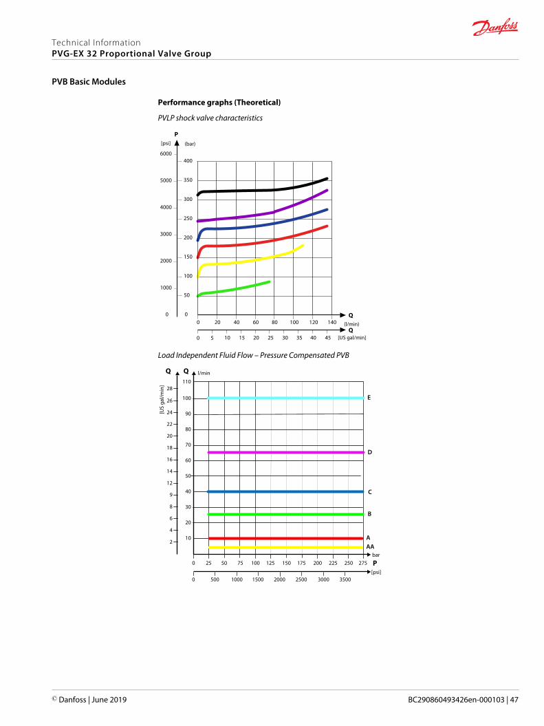
Performance graphs (Theoretical)
PVLP shock valve characteristics
(l/min)
[US gal/min]
P
Q
Q
(bar)[psi]
20 40 60 80 100 120 140
5 10 15 20 25 30 35 40 45
400
350
300
250
200
150
100
50
0
5000
4000
3000
2000
1000
0
6000
0
0
PVLP/PVLA suction valve characteristics
5 10 15 20 25 30 35 40 45 50 55 60 65 [l/min]
[US gal/min]
70 75 80
1 2 3 4 5 6 7 8 9 10 11 12 13 14 15 16 17 18 19 20 21
20
18
16
14
12
10
8
6
4
2
085 90 95 100
22 23 24 25 26
Q
28
26
24
22
PP
200
160
120
80
40
0
280
240
320
400
360
0
[psi] [bar]
0
Q105 110 115 120
27 28 29 30 31
PVLP
PVLA
Part numbers for uncompensated PVB
Part number A/B-port PVLP/PVLA LS A/B shuttle T0 facility
157B6000
G1/2"
— — —
157B6010 — — Yes
157B6030 Yes — —
11071832 Yes Yes —
Technical InformationPVG-EX 32 Proportional Valve Group
PVB Basic Modules
40 | © Danfoss | June 2019 BC290860493426en-000103

Part numbers for uncompensated PVB (continued)
Part number A/B-port PVLP/PVLA LS A/B shuttle T0 facility
157B6400
7/8–14 UNF
— — —
157B6410 — — Yes
157B6430 Yes — —
Technical InformationPVG-EX 32 Proportional Valve Group
PVB Basic Modules
© Danfoss | June 2019 BC290860493426en-000103 | 41
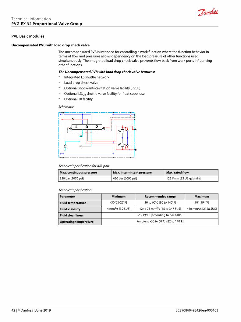
Uncompensated PVB with load drop check valve
The uncompensated PVB is intended for controlling a work function where the function behavior interms of flow and pressures allows dependency on the load pressure of other functions usedsimultaneously. The integrated load drop check valve prevents flow back from work ports influencingother functions.
The Uncompensated PVB with load drop check valve features:• Integrated LS shuttle network• Load drop check valve• Optional shock/anti-cavitation valve facility (PVLP)• Optional LSA/B shuttle valve facility for float spool use• Optional T0 facility
Schematic
A
B
1 0 2
Technical specification for A/B-port
Max. continuous pressure Max. intermittent pressure Max. rated flow
350 bar [5076 psi] 420 bar [6090 psi] 125 l/min [33 US gal/min]
Technical specification
Parameter Minimum Recommended range Maximum
Fluid temperature -30°C [-22°F] 30 to 60°C [86 to 140°F] 90° [194°F]
Fluid viscosity 4 mm2/s [39 SUS] 12 to 75 mm2/s [65 to 347 SUS] 460 mm2/s [2128 SUS]
Fluid cleanliness 23/19/16 (according to ISO 4406)
Operating temperature Ambient: -30 to 60°C [-22 to 140°F]
Technical InformationPVG-EX 32 Proportional Valve Group
PVB Basic Modules
42 | © Danfoss | June 2019 BC290860493426en-000103

Performance graphs (Theoretical)
PVLP shock valve characteristics
(l/min)
[US gal/min]
P
Q
Q
(bar)[psi]
20 40 60 80 100 120 140
5 10 15 20 25 30 35 40 45
400
350
300
250
200
150
100
50
0
5000
4000
3000
2000
1000
0
6000
0
0
PVLP/PVLA suction valve characteristics
5 10 15 20 25 30 35 40 45 50 55 60 65 [l/min]
[US gal/min]
70 75 80
1 2 3 4 5 6 7 8 9 10 11 12 13 14 15 16 17 18 19 20 21
20
18
16
14
12
10
8
6
4
2
085 90 95 100
22 23 24 25 26
Q
28
26
24
22
PP
200
160
120
80
40
0
280
240
320
400
360
0
[psi] [bar]
0
Q105 110 115 120
27 28 29 30 31
PVLP
PVLA
Part numbers for Uncomp. PVB with load drop check valve
Part number A/B-port PVLP/PVLA LS A/B shuttle T0 facility
157B6100 G1/2" — — —
157B6500 7/8–14 UNF — — —
157B6110 G1/2" — — Yes
157B6909 7/8–14 UNF — — Yes
Technical InformationPVG-EX 32 Proportional Valve Group
PVB Basic Modules
© Danfoss | June 2019 BC290860493426en-000103 | 43
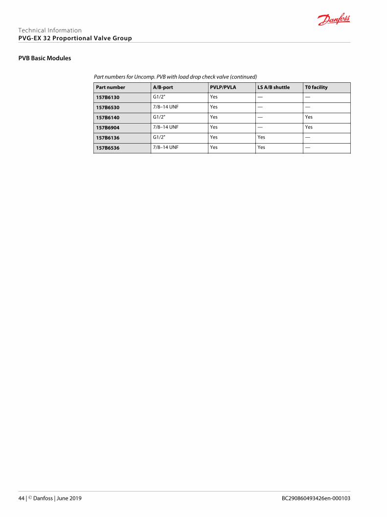
Part numbers for Uncomp. PVB with load drop check valve (continued)
Part number A/B-port PVLP/PVLA LS A/B shuttle T0 facility
157B6130 G1/2" Yes — —
157B6530 7/8–14 UNF Yes — —
157B6140 G1/2" Yes — Yes
157B6904 7/8–14 UNF Yes — Yes
157B6136 G1/2" Yes Yes —
157B6536 7/8–14 UNF Yes Yes —
Technical InformationPVG-EX 32 Proportional Valve Group
PVB Basic Modules
44 | © Danfoss | June 2019 BC290860493426en-000103
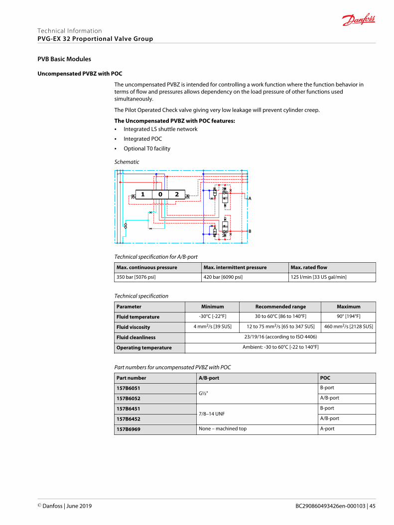
Uncompensated PVBZ with POC
The uncompensated PVBZ is intended for controlling a work function where the function behavior interms of flow and pressures allows dependency on the load pressure of other functions usedsimultaneously.
The Pilot Operated Check valve giving very low leakage will prevent cylinder creep.
The Uncompensated PVBZ with POC features:• Integrated LS shuttle network
• Integrated POC
• Optional T0 facility
Schematic
1 0 2A
B
Technical specification for A/B-port
Max. continuous pressure Max. intermittent pressure Max. rated flow
350 bar [5076 psi] 420 bar [6090 psi] 125 l/min [33 US gal/min]
Technical specification
Parameter Minimum Recommended range Maximum
Fluid temperature -30°C [-22°F] 30 to 60°C [86 to 140°F] 90° [194°F]
Fluid viscosity 4 mm2/s [39 SUS] 12 to 75 mm2/s [65 to 347 SUS] 460 mm2/s [2128 SUS]
Fluid cleanliness 23/19/16 (according to ISO 4406)
Operating temperature Ambient: -30 to 60°C [-22 to 140°F]
Part numbers for uncompensated PVBZ with POC
Part number A/B-port POC
157B6051G½"
B-port
157B6052 A/B-port
157B64517/8–14 UNF
B-port
157B6452 A/B-port
157B6969 None – machined top A-port
Technical InformationPVG-EX 32 Proportional Valve Group
PVB Basic Modules
© Danfoss | June 2019 BC290860493426en-000103 | 45

Compensated PVB
The compensated PVB is intended for controlling a work function where the function behavior in termsof flow and pressures requires independence on the load pressure of other functions usedsimultaneously.
The Compensated PVB features:• Integrated LS shuttle network
• Integrated compensator
• Optional shock/anti-cavitation valve facility (PVLP)
• Optional T0 facility and external T0 port
Compensated PVB schematic
1 0 2
A
PpT0LXPT
B
Technical specification for A/B-port
Max. continuous pressure Max. intermittent pressure Max. rated flow *
350 bar [5067 psi] 420 bar [6090 psi] 125 l/min [33 US gal/min]* With turbo function spool @ max rated flow of 130 l/min is possible
Technical specification
Parameter Minimum Recommended range Maximum
Fluid temperature -30°C [-22°F] 30 to 60°C [86 to 140°F] 90° [194°F]
Fluid viscosity 4 mm2/s [39 SUS] 12 to 75 mm2/s [65 to 347 SUS] 460 mm2/s [2128 SUS]
Fluid cleanliness 23/19/16 (according to ISO 4406)
Operating temperature Ambient: -30 to 60°C [-22 to 140°F]
Technical InformationPVG-EX 32 Proportional Valve Group
PVB Basic Modules
46 | © Danfoss | June 2019 BC290860493426en-000103
Performance graphs (Theoretical)
PVLP shock valve characteristics
(l/min)
[US gal/min]
P
Q
Q
(bar)[psi]
20 40 60 80 100 120 140
5 10 15 20 25 30 35 40 45
400
350
300
250
200
150
100
50
0
5000
4000
3000
2000
1000
0
6000
0
0
Load Independent Fluid Flow – Pressure Compensated PVB
10
20
30
40
50
60
70
80
90
100
l/min
[US
gal/m
in]
2
4
6
8
9
12
14
16
18
20
22
24
26
2502252001751501251007550250 275 P
25002000150010005000 35003000
bar
[psi]
11028
AA
B
C
D
A
E
Technical InformationPVG-EX 32 Proportional Valve Group
PVB Basic Modules
© Danfoss | June 2019 BC290860493426en-000103 | 47

PVLP/PVLA suction valve characteristics
5 10 15 20 25 30 35 40 45 50 55 60 65 [l/min]
[US gal/min]
70 75 80
1 2 3 4 5 6 7 8 9 10 11 12 13 14 15 16 17 18 19 20 21
20
18
16
14
12
10
8
6
4
2
085 90 95 100
22 23 24 25 26
Q
28
26
24
22
PP
200
160
120
80
40
0
280
240
320
400
360
0
[psi] [bar]
0
Q105 110 115 120
27 28 29 30 31
PVLP
PVLA
Part numbers for compensated PVB
Part number A/B-port PVLP/PVLA T0
157B6200
G1/2"
– –
157B6210 – Yes
157B6230 Yes –
157B6240 Yes Yes
157B6600
7/8–14 UNF
– –
157B6922 – Yes
157B6630 Yes –
157B6906 Yes Yes
157B6850 M22x1.5 Yes Yes
157B6849 None* – –
* Machined top, prepared for mounting of a PVBD diverter.
Technical InformationPVG-EX 32 Proportional Valve Group
PVB Basic Modules
48 | © Danfoss | June 2019 BC290860493426en-000103

Dampened Compensated PVB
The compensated PVB is intended for controlling a work function where the function behavior in termsof flow and pressures requires independence on the load pressure of other functions usedsimultaneously. The dampening of the compensator reaction will slow down the system therebyremoving instability.
The dampened compensated PVB features:• Integrated LS shuttle network
• Integrated compensator
• Optional shock/anti-cavitation valve facility (PVLP)
Compensated PVB schematic
A
B
1 0 2
T P LX Pp
Technical specification for A/B-port
Max. continuous pressure Max. intermittent pressure Max. rated flow*
350 bar [5076 psi] 420 bar [6090 psi] 125 l/min [33 US gal/min]* With turbo function spool @ max rated flow of 130 l/min is possible
Technical specification
Parameter Minimum Recommended range Maximum
Fluid temperature -30°C [-22°F] 30 to 60°C [86 to 140°F] 90° [194°F]
Fluid viscosity 4 mm2/s [39 SUS] 12 to 75 mm2/s [65 to 347 SUS] 460 mm2/s [2128 SUS]
Fluid cleanliness 23/19/16 (according to ISO 4406)
Operating temperature Ambient: -30 to 60°C [-22 to 140°F]
Technical InformationPVG-EX 32 Proportional Valve Group
PVB Basic Modules
© Danfoss | June 2019 BC290860493426en-000103 | 49

Performance graphs (Theoretical)
PVLP shock valve characteristics
(l/min)
[US gal/min]
P
Q
Q
(bar)[psi]
20 40 60 80 100 120 140
5 10 15 20 25 30 35 40 45
400
350
300
250
200
150
100
50
0
5000
4000
3000
2000
1000
0
6000
0
0
Load Independent Fluid Flow – Pressure Compensated PVB
10
20
30
40
50
60
70
80
90
100
l/min
[US
gal/m
in]
2
4
6
8
9
12
14
16
18
20
22
24
26
2502252001751501251007550250 275 P
25002000150010005000 35003000
bar
[psi]
11028
AA
B
C
D
A
E
Technical InformationPVG-EX 32 Proportional Valve Group
PVB Basic Modules
50 | © Danfoss | June 2019 BC290860493426en-000103

PVLP/PVLA suction valve characteristics
5 10 15 20 25 30 35 40 45 50 55 60 65 [l/min]
[US gal/min]
70 75 80
1 2 3 4 5 6 7 8 9 10 11 12 13 14 15 16 17 18 19 20 21
20
18
16
14
12
10
8
6
4
2
085 90 95 100
22 23 24 25 26
Q
28
26
24
22
PP
200
160
120
80
40
0
280
240
320
400
360
0
[psi] [bar]
0
Q105 110 115 120
27 28 29 30 31
PVLP
PVLA
Part numbers for damp. compensated PVB
Part number A/B-port PVLP/PVLA
157B6206G1/2"
–
157B6236 Yes
110366297/8–14 UNF
–
11036630 Yes
Technical InformationPVG-EX 32 Proportional Valve Group
PVB Basic Modules
© Danfoss | June 2019 BC290860493426en-000103 | 51

Dampened compensated PVB with LS A/B
The compensated PVB is intended for controlling a work function where the function behavior in termsof flow and pressures requires independence on the load pressure of other functions usedsimultaneously. The dampening of the compensator reaction will slow down the system therebyremoving instability. The integrated LSA/B relief valve is used to limit the maximum work port build-up onthe A/B-ports individually.
The dampened compensated PVB with LS A/B features:
• Integrated LS shuttle network• Integrated compensator• Integrated adjustable LSA/B pressure relief valves• External LSA/B port connection• Optional shock/anti-cavitation valve facility (PVLP)
Dampened compensated PVB with LS A/B schematic
1 0 2A
B
B
LSA
LS
T P LS
Technical specification for A/B-port
Max. continuous pressure Max. intermittent pressure Max. rated flow*
350 bar [5076 psi] 420 bar [6090 psi] 125 l/min [33 US gal/min]* With turbo function spool @ max rated flow of 130 l/min is possible
Parameter Minimum Recommended range Maximum
Fluid temperature -30°C [-22°F] 30 to 60°C [86 to 40°F] 90°C [194°F]
Fluid viscosity 4 mm2/s [39 SUS] 12 to 75 mm2/s [65 to 347SUS]
460 mm2/s [2128 SUS]
Fluid cleanliness 23/19/16 (according to ISO 4406)
Operating temperature Ambient: -30 to 60°C [-22 to 140°F]
Technical InformationPVG-EX 32 Proportional Valve Group
PVB Basic Modules
52 | © Danfoss | June 2019 BC290860493426en-000103

Performance graphs (Theoretical)
PVLP shock valve characteristics
(l/min)
[US gal/min]
P
Q
Q
(bar)[psi]
20 40 60 80 100 120 140
5 10 15 20 25 30 35 40 45
400
350
300
250
200
150
100
50
0
5000
4000
3000
2000
1000
0
6000
0
0
Load Independent Fluid Flow – Pressure Compensated PVB
5
10
15
20
25
30
35
40
45
50
55
60
65
(l/min) [US gal/min]
70
1
2
3
4
5
6
7
8
9
10
11
12
13
14
15
16
17
18
0 25 50 75 100 125 150 175 200 225 250 275 300
0 500 1000 1500 2000 2500 3000 3500 4000
P
AA
B
C
D
A
P(bar)
[psi]
A = 10 l/minB = 15 l/min
AA = 5/min
C = 25 l/minD = 40 l/min
Technical InformationPVG-EX 32 Proportional Valve Group
PVB Basic Modules
© Danfoss | June 2019 BC290860493426en-000103 | 53

PVLP/PVLA suction valve characteristics
5 10 15 20 25 30 35 40 45 50 55 60 65 [l/min]
[US gal/min]
70 75 80
1 2 3 4 5 6 7 8 9 10 11 12 13 14 15 16 17 18 19 20 21
20
18
16
14
12
10
8
6
4
2
085 90 95 100
22 23 24 25 26
Q
28
26
24
22
PP
200
160
120
80
40
0
280
240
320
400
360
0
[psi] [bar]
0
Q105 110 115 120
27 28 29 30 31
PVLP
PVLA
PVB pressure compensated for LS A/B characteristics
(l/min) [US gal/min]
P
Q
P(bar)
[psi]
5
10
15
20
25
30
35
40
45
50
55
60
65
70
1
2
3
4
5
6
7
8
9
10
11
12
13
14
15
16
17
18
2502252001751501251007550250 350325300275
25002000150010005000 35003000 4000 50004500
0
Part number A/B-port LS-port PVLP/PVLA
157B6208G1/2 G1/4
-
157B6238 Yes
Technical InformationPVG-EX 32 Proportional Valve Group
PVB Basic Modules
54 | © Danfoss | June 2019 BC290860493426en-000103

Compensated PVB with LS A/B
The compensated PVB is intended for controlling a work function where the function behavior in termsof flow and pressures requires independency on the load pressure of other functions usedsimultaneously. The integrated LSA/B relief valve is used to limit the maximum work port build-up on theA/B-ports individually.
The compensated PVB with LSA/B features:• Integrated LS shuttle network
• Integrated compensator
• Integrated adjustable LSA/B pressure relief valves
• External LSA/B port connection
• Integrated LSA/B shuttle valve for float spool usage
• Optional shock/anti-cavitation valve facility (PVLP)
• Optional T0 facility
Compensated PVB with LS schematic
A
PpT0LXPT
B
LSB
LSA
1 0 2
Technical specification for A/B-port
Max. continuous pressure Max. intermittent pressure Max. rated flow*
350 bar [5076 psi] 420 bar [6090 psi] 125 l/min [33 US gal/min]* With turbo function spool @ max rated flow of 130 l/min is possible
Technical specification
Parameter Minimum Recommended range Maximum
Fluid temperature -30°C [-22°F] 30 to 60°C [86 to 140°F] 90° [194°F]
Fluid viscosity 4 mm2/s [39 SUS] 12 to 75 mm2/s [65 to 347 SUS] 460 mm2/s [2128 SUS]
Fluid cleanliness 23/19/16 (according to ISO 4406)
Operating temperature Ambient: -30 to 60°C [-22 to 140°F]
Technical InformationPVG-EX 32 Proportional Valve Group
PVB Basic Modules
© Danfoss | June 2019 BC290860493426en-000103 | 55

Performance graphs (Theoretical)
PVLP shock valve characteristics
(l/min)
[US gal/min]
P
Q
Q
(bar)[psi]
20 40 60 80 100 120 140
5 10 15 20 25 30 35 40 45
400
350
300
250
200
150
100
50
0
5000
4000
3000
2000
1000
0
6000
0
0
Load Independent Fluid Flow – Pressure Compensated PVB
10
20
30
40
50
60
70
80
90
100
l/min
[US
gal/m
in]
2
4
6
8
9
12
14
16
18
20
22
24
26
2502252001751501251007550250 275 P
25002000150010005000 35003000
bar
[psi]
11028
AA
B
C
D
A
E
Technical InformationPVG-EX 32 Proportional Valve Group
PVB Basic Modules
56 | © Danfoss | June 2019 BC290860493426en-000103

PVLP/PVLA suction valve characteristics
5 10 15 20 25 30 35 40 45 50 55 60 65 [l/min]
[US gal/min]
70 75 80
1 2 3 4 5 6 7 8 9 10 11 12 13 14 15 16 17 18 19 20 21
20
18
16
14
12
10
8
6
4
2
085 90 95 100
22 23 24 25 26
Q
28
26
24
22
PP
200
160
120
80
40
0
280
240
320
400
360
0
[psi] [bar]
0
Q105 110 115 120
27 28 29 30 31
PVLP
PVLA
PVB pressure compensated for LS A/B characteristics
10
20
30
40
50
60
70
80
90
100
l/min US gal/min
2
4
6
8
10
12
14
16
18
20
22
24
26
11028
AA
B
C
D
A
2502252001751501251007550250 350325300275
P
P25002000150010005000 35003000 4000 50004500
bar
psi
E
Q
Technical InformationPVG-EX 32 Proportional Valve Group
PVB Basic Modules
© Danfoss | June 2019 BC290860493426en-000103 | 57
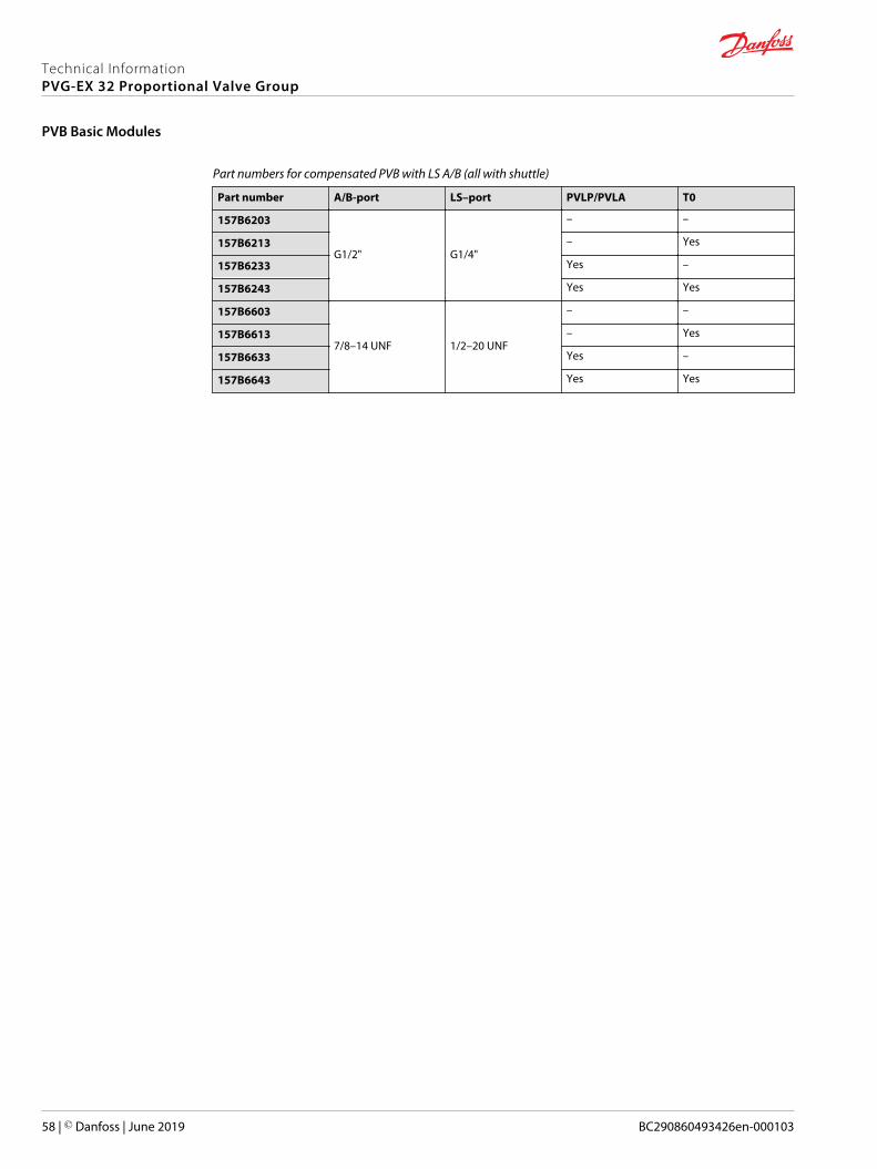
Part numbers for compensated PVB with LS A/B (all with shuttle)
Part number A/B-port LS–port PVLP/PVLA T0
157B6203
G1/2" G1/4"
– –
157B6213 – Yes
157B6233 Yes –
157B6243 Yes Yes
157B6603
7/8–14 UNF 1/2–20 UNF
– –
157B6613 – Yes
157B6633 Yes –
157B6643 Yes Yes
Technical InformationPVG-EX 32 Proportional Valve Group
PVB Basic Modules
58 | © Danfoss | June 2019 BC290860493426en-000103

Compensated high flow PVB
The compensated PVB is intended for controlling a work function where the function behavior in termsof flow and pressures requires independence on the load pressure of other functions usedsimultaneously.
The bleed-off will prevent pressure build-up on the work ports in neutral.
Features
• Integrated LS shuttle network• Integrated high flow compensator with bleed-off• Integrated adjustable LSA/B pressure relief valves• Optional shock/anti-cavitation valve facility (PVLP)• Optional T0 facility
Compensated high flow PVB schematic
1 0 2A
B
Technical specification for A/B-port
Max. continuous pressure Max. intermittent pressure Max. rated flow
350 bar [5076 psi] 420 bar [6090 psi] 130 l/min [34 US gal/min]
Technical specification
Parameter Minimum Recommended range Maximum
Fluid temperature -30°C [-22°F] 30 to 60°C [86 to 140°F] 90° [194°F]
Fluid viscosity 4 mm2/s [39 SUS] 12 to 75 mm2/s [65 to 347 SUS] 460 mm2/s [2128 SUS]
Fluid cleanliness 23/19/16 (according to ISO 4406)
Operating temperature Ambient: -30 to 60°C [-22 to 140°F]
Technical InformationPVG-EX 32 Proportional Valve Group
PVB Basic Modules
© Danfoss | June 2019 BC290860493426en-000103 | 59
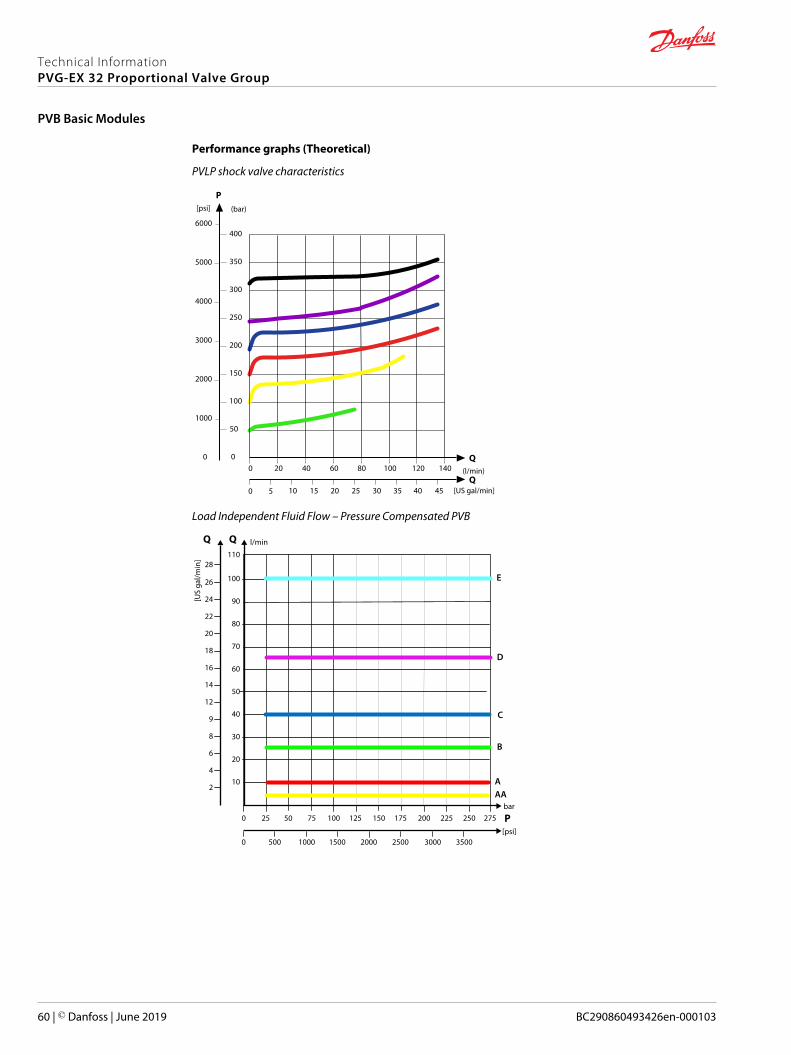
Performance graphs (Theoretical)
PVLP shock valve characteristics
(l/min)
[US gal/min]
P
Q
Q
(bar)[psi]
20 40 60 80 100 120 140
5 10 15 20 25 30 35 40 45
400
350
300
250
200
150
100
50
0
5000
4000
3000
2000
1000
0
6000
0
0
Load Independent Fluid Flow – Pressure Compensated PVB
10
20
30
40
50
60
70
80
90
100
l/min
[US
gal/m
in]
2
4
6
8
9
12
14
16
18
20
22
24
26
2502252001751501251007550250 275 P
25002000150010005000 35003000
bar
[psi]
11028
AA
B
C
D
A
E
Technical InformationPVG-EX 32 Proportional Valve Group
PVB Basic Modules
60 | © Danfoss | June 2019 BC290860493426en-000103

PVLP/PVLA suction valve characteristics
5 10 15 20 25 30 35 40 45 50 55 60 65 [l/min]
[US gal/min]
70 75 80
1 2 3 4 5 6 7 8 9 10 11 12 13 14 15 16 17 18 19 20 21
20
18
16
14
12
10
8
6
4
2
085 90 95 100
22 23 24 25 26
Q
28
26
24
22
PP
200
160
120
80
40
0
280
240
320
400
360
0
[psi] [bar]
0
Q105 110 115 120
27 28 29 30 31
PVLP
PVLA
Part numbers for compensated high flow PVB
Part number A/B-port PVLP/PVLA LS A/B shuttle T0 facility
11091947
7/8–14 UNF
Yes Yes Yes
11119463 — — Yes
11126962 — — Yes
157B6938 Yes — —
157B6852 G½" Yes — —
Technical InformationPVG-EX 32 Proportional Valve Group
PVB Basic Modules
© Danfoss | June 2019 BC290860493426en-000103 | 61
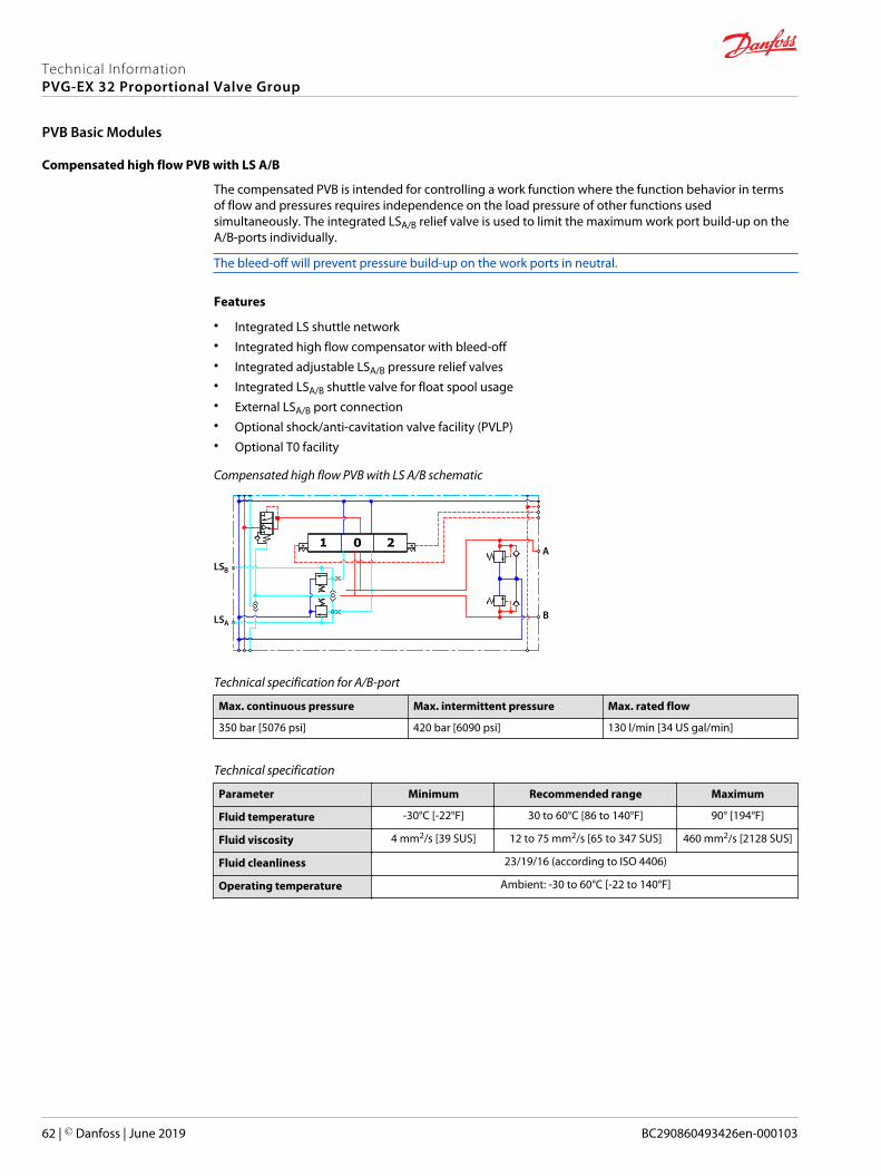
Compensated high flow PVB with LS A/B
The compensated PVB is intended for controlling a work function where the function behavior in termsof flow and pressures requires independence on the load pressure of other functions usedsimultaneously. The integrated LSA/B relief valve is used to limit the maximum work port build-up on theA/B-ports individually.
The bleed-off will prevent pressure build-up on the work ports in neutral.
Features
• Integrated LS shuttle network• Integrated high flow compensator with bleed-off• Integrated adjustable LSA/B pressure relief valves• Integrated LSA/B shuttle valve for float spool usage• External LSA/B port connection• Optional shock/anti-cavitation valve facility (PVLP)• Optional T0 facility
Compensated high flow PVB with LS A/B schematic
1 0 2A
B
B
LSA
LS
Technical specification for A/B-port
Max. continuous pressure Max. intermittent pressure Max. rated flow
350 bar [5076 psi] 420 bar [6090 psi] 130 l/min [34 US gal/min]
Technical specification
Parameter Minimum Recommended range Maximum
Fluid temperature -30°C [-22°F] 30 to 60°C [86 to 140°F] 90° [194°F]
Fluid viscosity 4 mm2/s [39 SUS] 12 to 75 mm2/s [65 to 347 SUS] 460 mm2/s [2128 SUS]
Fluid cleanliness 23/19/16 (according to ISO 4406)
Operating temperature Ambient: -30 to 60°C [-22 to 140°F]
Technical InformationPVG-EX 32 Proportional Valve Group
PVB Basic Modules
62 | © Danfoss | June 2019 BC290860493426en-000103

Performance graphs (Theoretical)
PVLP shock valve characteristics
(l/min)
[US gal/min]
P
Q
Q
(bar)[psi]
20 40 60 80 100 120 140
5 10 15 20 25 30 35 40 45
400
350
300
250
200
150
100
50
0
5000
4000
3000
2000
1000
0
6000
0
0
Load Independent Fluid Flow – Pressure Compensated PVB
10
20
30
40
50
60
70
80
90
100
l/min
[US
gal/m
in]
2
4
6
8
9
12
14
16
18
20
22
24
26
2502252001751501251007550250 275 P
25002000150010005000 35003000
bar
[psi]
11028
AA
B
C
D
A
E
Technical InformationPVG-EX 32 Proportional Valve Group
PVB Basic Modules
© Danfoss | June 2019 BC290860493426en-000103 | 63

PVLP/PVLA suction valve characteristics
5 10 15 20 25 30 35 40 45 50 55 60 65 [l/min]
[US gal/min]
70 75 80
1 2 3 4 5 6 7 8 9 10 11 12 13 14 15 16 17 18 19 20 21
20
18
16
14
12
10
8
6
4
2
085 90 95 100
22 23 24 25 26
Q
28
26
24
22
PP
200
160
120
80
40
0
280
240
320
400
360
0
[psi] [bar]
0
Q105 110 115 120
27 28 29 30 31
PVLP
PVLA
PVB pressure compensated for LS A/B characteristics
10
20
30
40
50
60
70
80
90
100
l/min US gal/min
2
4
6
8
10
12
14
16
18
20
22
24
26
11028
AA
B
C
D
A
2502252001751501251007550250 350325300275
P
P25002000150010005000 35003000 4000 50004500
bar
psi
E
Q
Technical InformationPVG-EX 32 Proportional Valve Group
PVB Basic Modules
64 | © Danfoss | June 2019 BC290860493426en-000103

Part numbers for comp. high flow PVB with LS
Part number A/B-port LSA/B port PVLP/PVLA LSA/B shuttle T0 facility
157B6855
G½" G¼”
—
Yes
—
11059838 — Yes
157B6854 Yes —
11126963
7/8–14 UNF ½-20 UNF
— Yes
11126964 Yes Yes
11127277 Yes —
Technical InformationPVG-EX 32 Proportional Valve Group
PVB Basic Modules
© Danfoss | June 2019 BC290860493426en-000103 | 65

Compensated PVBZ with POC
The compensated PVB is intended for controlling a work function where the function behavior in termsof flow and pressures requires independence on the load pressure of other functions usedsimultaneously.
The bleed-off will prevent pressure build-up on the work ports in neutral.
Features
• Integrated LS shuttle network• Integrated compensator• Integrated POC• T0 facility• Optional LSA/B shuttle valve facility for float spool use• Optional thermo-relief valve
Schematic
A
B
1 0 2
Technical specification for A/B-port
Max. continuous pressure Max. intermittent pressure Max. rated flow
350 bar [5076 psi] 420 bar [6090 psi] 100 l/min [26 US gal/min]
Technical specification
Parameter Minimum Recommended range Maximum
Fluid temperature -30°C [-22°F] 30 to 60°C [86 to 140°F] 90° [194°F]
Fluid viscosity 4 mm2/s [39 SUS] 12 to 75 mm2/s [65 to 347 SUS] 460 mm2/s [2128 SUS]
Fluid cleanliness 23/19/16 (according to ISO 4406)
Operating temperature Ambient: -30 to 60°C [-22 to 140°F]
Technical InformationPVG-EX 32 Proportional Valve Group
PVB Basic Modules
66 | © Danfoss | June 2019 BC290860493426en-000103

Performance graphs (Theoretical)
Load Independent Fluid Flow – Pressure Compensated PVB
10
20
30
40
50
60
70
80
90
100
l/min
[US
gal/m
in]
2
4
6
8
9
12
14
16
18
20
22
24
26
2502252001751501251007550250 275 P
25002000150010005000 35003000
bar
[psi]
11028
AA
B
C
D
A
E
Part numbers for compensated PVBZ with POC
Part number A/B-port POC LSA/B shuttle Thermo relief
157B6251
G1/2"
B-port — —
157B6252 A/B-port — —
157B6261 B-port — Yes
157B6262 A/B-port — Yes
157B6266 A/B-port Yes Yes
157B6960 A-port —
157B6651
7/8–14 UNF
B-port — —
157B6652 A/B-port — —
157B6661 A/B-port — Yes
157B6662 A/B-port — Yes
157B6666 A/B-port Yes Yes
157B6954 M22x1.5 mm A/B-port Yes Yes
157B6952 None – machined top A/B-port Yes Yes
157B6958 None – machined top A/B-port Yes Yes
11157082 None – machined top A-port — —
Technical InformationPVG-EX 32 Proportional Valve Group
PVB Basic Modules
© Danfoss | June 2019 BC290860493426en-000103 | 67
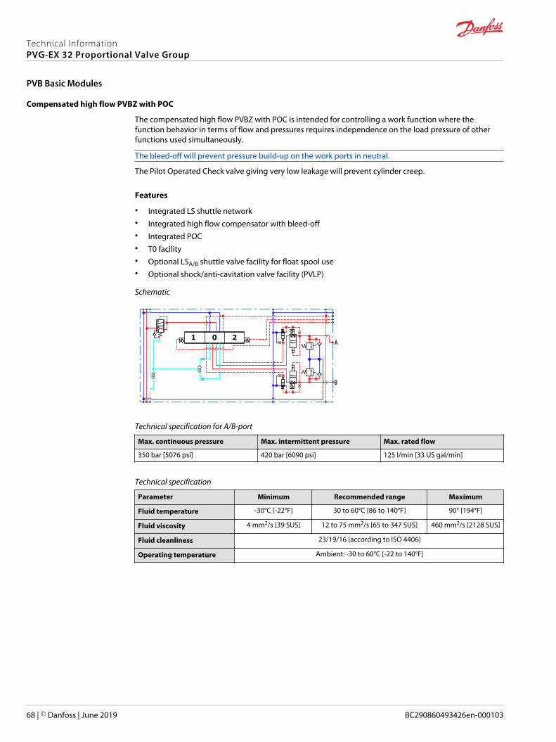
Compensated high flow PVBZ with POC
The compensated high flow PVBZ with POC is intended for controlling a work function where thefunction behavior in terms of flow and pressures requires independence on the load pressure of otherfunctions used simultaneously.
The bleed-off will prevent pressure build-up on the work ports in neutral.
The Pilot Operated Check valve giving very low leakage will prevent cylinder creep.
Features
• Integrated LS shuttle network• Integrated high flow compensator with bleed-off• Integrated POC• T0 facility• Optional LSA/B shuttle valve facility for float spool use• Optional shock/anti-cavitation valve facility (PVLP)
Schematic
1 0 2A
B
Technical specification for A/B-port
Max. continuous pressure Max. intermittent pressure Max. rated flow
350 bar [5076 psi] 420 bar [6090 psi] 125 l/min [33 US gal/min]
Technical specification
Parameter Minimum Recommended range Maximum
Fluid temperature -30°C [-22°F] 30 to 60°C [86 to 140°F] 90° [194°F]
Fluid viscosity 4 mm2/s [39 SUS] 12 to 75 mm2/s [65 to 347 SUS] 460 mm2/s [2128 SUS]
Fluid cleanliness 23/19/16 (according to ISO 4406)
Operating temperature Ambient: -30 to 60°C [-22 to 140°F]
Technical InformationPVG-EX 32 Proportional Valve Group
PVB Basic Modules
68 | © Danfoss | June 2019 BC290860493426en-000103

Performance graphs (Theoretical)
PVLP shock valve characteristics
(l/min)
[US gal/min]
P
Q
Q
(bar)[psi]
20 40 60 80 100 120 140
5 10 15 20 25 30 35 40 45
400
350
300
250
200
150
100
50
0
5000
4000
3000
2000
1000
0
6000
0
0
Load Independent Fluid Flow – Pressure Compensated PVB
10
20
30
40
50
60
70
80
90
100
l/min
[US
gal/m
in]
2
4
6
8
9
12
14
16
18
20
22
24
26
2502252001751501251007550250 275 P
25002000150010005000 35003000
bar
[psi]
11028
AA
B
C
D
A
E
Part numbers for high flow PVBZ with POC
Part number A/B-port PVLP/PVLA LS A/B shuttle T0 facility
11119463
7/8–14 UNF
— — Yes
11126962 — — Yes
157B6938 Yes — —
157B6852 G½" Yes — —
Technical InformationPVG-EX 32 Proportional Valve Group
PVB Basic Modules
© Danfoss | June 2019 BC290860493426en-000103 | 69

Compensated high flow PVBZ with POC and manifold interface
The compensated PVB is intended for controlling a work function where the function behavior in termsof flow and pressures requires independence on the load pressure of other functions usedsimultaneously.
The integrated LSA/B relief valve is used to limit the maximum work port build-up on the A/B-portsindividually.
The bleed-off will prevent pressure build-up on the work ports in neutral.
Features
• Integrated LS shuttle network• Integrated high flow compensator with bleed-off• Integrated POC• T0 facility• Integrated adjustable LSA/B pressure relief valves• Optional thermo relief valve
Schematic
1 0 21 0 2
A
B
A
B
Technical specification for A/B-port
Max. continuous pressure Max. intermittent pressure Max. rated flow
350 bar [5076 psi] 420 bar [6090 psi] 125 l/min [33 US gal/min]
Technical specification
Parameter Minimum Recommended range Maximum
Fluid temperature -30°C [-22°F] 30 to 60°C [86 to 140°F] 90° [194°F]
Fluid viscosity 4 mm2/s [39 SUS] 12 to 75 mm2/s [65 to 347 SUS] 460 mm2/s [2128 SUS]
Fluid cleanliness 23/19/16 (according to ISO 4406)
Operating temperature Ambient: -30 to 60°C [-22 to 140°F]
Technical InformationPVG-EX 32 Proportional Valve Group
PVB Basic Modules
70 | © Danfoss | June 2019 BC290860493426en-000103

Performance graphs (Theoretical)
Load Independent Fluid Flow – Pressure Compensated PVB
10
20
30
40
50
60
70
80
90
100
l/min
[US
gal/m
in]
2
4
6
8
9
12
14
16
18
20
22
24
26
2502252001751501251007550250 275 P
25002000150010005000 35003000
bar
[psi]
11028
AA
B
C
D
A
E
Part numbers for PVBZ - POC, manifold interface
Part number POC
157B6958 A/B-port
11005475 A/B-port
11032961 A/B-port
Technical InformationPVG-EX 32 Proportional Valve Group
PVB Basic Modules
© Danfoss | June 2019 BC290860493426en-000103 | 71

The generic PVB module accessory platform include the PVLP shock and anti-cavitation valve and PVLAsuction valve.• PVLP Shock and Anti-Cavitation Valve on page 72
• PVLA Suction Valve on page 74
PVLP Shock and Anti-Cavitation Valve
The PVLP shock and anti-cavitation valve will relieve a pressure peak to the internal tank galleries and willfurthermore suck oil from the tank to the work port to prevent cavitation. Pressure settings range: 32–400bar [460–5801 psi].
The pressure setting of the PVLP must always be 20 bar [290 psi] higher than LSA/B setting in the samemodule.
PVLP schematic
P109174
Port pressure
PVLP shock valve characteristics
(l/min)
[US gal/min]
P
Q
Q
(bar)[psi]
20 40 60 80 100 120 140
5 10 15 20 25 30 35 40 45
400
350
300
250
200
150
100
50
0
5000
4000
3000
2000
1000
0
6000
0
0
Technical InformationPVG-EX 32 Proportional Valve Group
PVB Basic Modules Accessories
72 | © Danfoss | June 2019 BC290860493426en-000103

PVLP/PVLA suction valve characteristics
5 10 15 20 25 30 35 40 45 50 55 60 65 [l/min]
[US gal/min]
70 75 80
1 2 3 4 5 6 7 8 9 10 11 12 13 14 15 16 17 18 19 20 21
20
18
16
14
12
10
8
6
4
2
085 90 95 100
22 23 24 25 26
Q
28
26
24
22
PP
200
160
120
80
40
0
280
240
320
400
360
0
[psi] [bar]
0
Q105 110 115 120
27 28 29 30 31
PVLP
PVLA
Technical specification
Parameter Minimum Recommended range Maximum
Fluid temperature -30°C [-22°F] 30 to 60°C [86 to 140°F] 90° [194°F]
Fluid viscosity 4 mm2/s [39 SUS] 12 to 75 mm2/s [65 to 347 SUS] 460 mm2/s [2128 SUS]
Fluid cleanliness 23/19/16 (according to ISO 4406)
Operating temperature Ambient: -30 to 60°C [-22 to 140°F]
Part numbers for PVLP according to pressure settings
Part number Pressure in bar [psi] Part number Pressure in bar [psi]
157B2032 32 [464] 157B2210 210 [3045]
157B2050 50 [725] 157B2230 230 [3335]
157B2063 63 [913] 157B2240 240 [3480]
157B2080 80 [1160] 157B2250 250 [3626]
157B2100 100 [1450] 157B2265 265 [3844]
157B2125 125 [1813] 157B2280 280 [4061]
157B2140 140 [2031] 157B2300 300 [4351]
157B2150 150 [2176] 157B2320 320 [4641]
157B2160 160 [2321] 157B2350 350 [5076]
157B2175 175 [2538] 157B2380 380 [5511]
157B2190 190 [2756] —
Technical InformationPVG-EX 32 Proportional Valve Group
PVB Basic Modules Accessories
© Danfoss | June 2019 BC290860493426en-000103 | 73

PVLA Suction Valve
The PVLA valve is an accessory available for PVB basic modules.
The PVLA will suck fluid from the tank to the work port to prevent cavitation by the 0.5 bar spring. Theplug will ensure that when using a single acting spool, all flow returning through the work port is led totank.
PVLA schematic
P109175
Port pressure
PVLP/PVLA suction valve characteristics
5 10 15 20 25 30 35 40 45 50 55 60 65 [l/min]
[US gal/min]
70 75 80
1 2 3 4 5 6 7 8 9 10 11 12 13 14 15 16 17 18 19 20 21
20
18
16
14
12
10
8
6
4
2
085 90 95 100
22 23 24 25 26
Q
28
26
24
22
PP
200
160
120
80
40
0
280
240
320
400
360
0
[psi] [bar]
0
Q105 110 115 120
27 28 29 30 31
PVLP
PVLA
Technical specification
Parameter Minimum Recommended range Maximum
Fluid temperature -30°C [-22°F] 30 to 60°C [86 to 140°F] 90° [194°F]
Fluid viscosity 4 mm2/s [39 SUS] 12 to 75 mm2/s [65 to 347 SUS] 460 mm2/s [2128 SUS]
Fluid cleanliness 23/19/16 (according to ISO 4406)
Operating temperature Ambient: -30 to 60°C [-22 to 140°F]
PVLA suction valve part number
PVLA suction valve Plug
157B2001 157B2002
Technical InformationPVG-EX 32 Proportional Valve Group
PVB Basic Modules Accessories
74 | © Danfoss | June 2019 BC290860493426en-000103

The main spools (PVBS) determine the flow out of the work section or the pressure build up, and arebased on a generic platform with a wide selection of additional features, enabling you to tailor the PVBSto suit the demands of any hydraulic system and any function.
The PVBS main spool can be activated in three different ways:• Mechanically by a PVM lever
• Electrically by a PVE/PVHC actuator
• Hydraulically by a PVH actuator
PVBS main spool
PVBS main spool dimensions
159 [6.26 ]
110 [4.33] 21.5 [0.85]
Weight: 0.25 kg [ 0.55 lb]
Technical specification
Parameter Minimum Recommended range Maximum
Fluid temperature -30°C [-22°F] 30 to 60°C [86 to 140°F] 90° [194°F]
Fluid viscosity 4 mm2/s [39 SUS] 12 to 75 mm2/s [65 to 347 SUS] 460 mm2/s [2128 SUS]
Fluid cleanliness 23/19/16 (according to ISO 4406)
Operating temperature Ambient: -30 to 60°C [-22 to 140°F]
Flow Control Spools(FC)
Flow control spools are for work sections where you want to control thespeed (flow) of the work port
Pressure ControlSpools (PC)
Pressure control spools are for work sections where you want to control thepower (pressure) of the work port
For more information on where to use flow control or pressure control spools see application guideAB00000079 - “Using flow or pressure control spools”
Closed neutralposition
In neutral position and inside of the deadband area the connection to tank isclosed
Throttled openneutral position
In neutral position and inside of the deadband area the connection to tank is 10% of the full flow function
Open/closed neutralposition (drain)
In total neutral position the connection to tank is less than 10 % of the full flowfunction. But when moving the spool out of neutral position but still withindead band area the connection will close.
Technical InformationPVG-EX 32 Proportional Valve Group
PVBS Main Spools
© Danfoss | June 2019 BC290860493426en-000103 | 75

PVBS fluid flow characteristics—Theoretical performance
Fluid flow at different spool travel + 10 bar margin (uncompensated PVB)
AP
20
40
60
80
100
120
140
160
180
200
[l/min] [US gal/min ]
4
8
12
16
20
24
28
32
36
40
44
48
52
BP
[mm]PVM765
[in]0.280.240.20
PVEUs
UDC
4
0.16
3210
0.120.080.040
PVH5bar
1597
psi
[mm]PVM
[in]
PVE
PVH
bar
psi
11 13
73 218130100 160 190
0.5 0.750.60.55 0.65 0.7
012
00.040.08
3
0.12
4567
0.160.200.240.28
15 51113 9 7
218 73160190 130 100
0.25 0.50.350.3 0.4 0.45
s
UDC
1
8
18
18
B
C
E
AAA
1
8
18
18
18 B
C
D
E
A
8
1
AA
U
Spool types:AA = 5 l/minA = 10 l/minB = 25 l/minC = 40 l/minD = 65 l/minE = 100 l/min
1 = First PVB efter PVP8 = Eighth PVB after PVP
Technical InformationPVG-EX 32 Proportional Valve Group
PVBS Main Spools
76 | © Danfoss | June 2019 BC290860493426en-000103

Fluid flow at different spool travel + 20 bar margin (uncompensated PVB)
AP
20
40
60
80
100
120
140
160
180
200
l/min US gal/min
4
8
12
16
20
24
28
32
36
40
44
48
52
BP
mm
PVM765
in0.280.240.20
PVE
4
0.16
3210
0.120.080.040
PVH5
bar1597
psi
mm
in
bar
psi11 13
73 218130100 160 190
0. 5 0.750. 60.55 0.65 0. 7
012
00.040.08
3
0.12
4567
0.160.200.240.28
15 51113 9 7
218 73160190 130 100
0.25 0. 50.350. 3 0. 4 0.45
s
UDC
18
18
18
B
C
D
E
A
8
1
AA
U
Spool types:AA = 5 l/minA = 10 l/minB = 25 l/minC = 40 l/minD = 65 l/minE = 100 l/min
1 = First PVB after PVP8 = Eighth PVB after PVP
s
UDC
U
18
18
18
B
C
D
E
A
8
1
AA
Technical InformationPVG-EX 32 Proportional Valve Group
PVBS Main Spools
© Danfoss | June 2019 BC290860493426en-000103 | 77

Progressive fluid flow characteristic depending on spool type
AP
10
20
30
40
50
60
70
80
90
100
l/min US gal/min
2
4
6
8
10
12
14
16
18
20
22
24
26
BP
mmmm765
in0.280.240.20
UsUDC
4
0.16
3210
0.120.080.040
5V
7.565.5PWM%
6.5 7
0.5 0.750.60.55 0.65 0.7
012
00.040.08
3
0.12
4567
0.160.200.240.28
2.5 53.53 4 4.5
80 0-106070 50 40
0.25 0.50.350.3 0.4 0.45
PVM
PVEA/M/H/S
PVEH-U/S-U
PVEP
1
8
1
8
18
B
C
D
E
AAA
B
C
D
E
AAA
1
8
1
8
18
110
120
130
28
30
32
34 FF
30 20 0-10 803020 40 50 60 70
Spool types:AA = 5 l/minA = 10 l/minB = 25 l/minC = 40 l/minE = 100 l/minF = 130 l/min
1 = First PVB after PVP8 = Eighth PVB after PVP
5bar
1597psi
11 13
73 218130100 160 190
15 51113 9 7
218 73160190 130 100
PVH
in
UsUDC
V
PWM%
bar
psi
Linear fluid flow characteristic depending on spool type
10
00
1 2 3 4 5 6 701234567
20
30
40
50
60
70
80
90
100l/min
2
4
6
8
10
12
14
16
18
20
22
24
26
BP
Q
mm[in]
mm[in]
UsUDC
bar[psi]
B
C
D
E
1
8
1
8
1
8
AP US gal/min
2
4
6
8
10
12
14
16
18
20
22
24
26US gal/min
0.75 0.50.650.7 0.6 0.55
PVM
PVEH0.5 0.750.60.55 0.65 0.7
B
C
D
E
1
8
1
8
1
8
PVH5
[73]5
[73]159 11 13
[218][130]9
[130] [100] [160]11
[160] [190]7
[100]7
bar[psi] 15 13
[218] [190]
UsUDC
[0.28][0.24][0.20][0.16][0.12][0.08][0.04][0.28] [0.24] [0.20] [0.16] [0.12] [0.08] [0.04]
Spool types:B = 25 l/minC = 40 l/minD = 65 l/minE = 100 l/min
1 = First PVB after PVP8 = Eighth PVB after PVP
Technical InformationPVG-EX 32 Proportional Valve Group
PVBS Main Spools
78 | © Danfoss | June 2019 BC290860493426en-000103

Progressive fluid flow characteristic of spool with A-float
10
0 1 2 3 4 5 6 701234567
20
30
40
50
60
70
80
90
100l/min
2
4
6
8
10
12
14
16
18
20
22
24
26
BP
Q
mm[in]
mm[in]
UsUDC
bar[psi]
AP US gal/min
2
4
6
8
10
12
14
16
18
20
22
24
26US gal/min
0.75 0.50.650.7 0.6 0.55
PVM
PVE0.5 0.750.60.55 0.65 0.7
PVH5
[73]5
[73]159 11 13
[218][130]9
[130] [100] [160]11
[160] [190]7
[100]7
bar[psi] 15 13
[218] [190]
UsUDC
[0.28][0.24][0.20][0.16][0.12][0.08][0.04][0.28] [0.24] [0.20] [0.16] [0.12] [0.08] [0.04]
Spool types:B = 25 l/minC = 40 l/minD = 65 l/minE = 100 l/min
C
D
E
B
C
D
E
B
Progressive fluid flow characteristic of spool with B-float
10
0 1 2 3 4 5 6 701234567
20
30
40
50
60
70
80
90
100l/min
2
4
6
8
10
12
14
16
18
20
22
24
26
BP
Q
mm[in]
mm[in]
UsUDC
bar[psi]
AP US gal/min
2
4
6
8
10
12
14
16
18
20
22
24
26US gal/min
0.75 0.50.650.7 0.6 0.55
PVM
PVE0.5 0.750.60.55 0.65 0.7
PVH5
[73]5
[73]159 11 13
[218][130]9
[130] [100] [160]11
[160] [190]7
[100]7
bar[psi] 15 13
[218] [190]
UsUDC
[0.28][0.24][0.20][0.16][0.12][0.08][0.04][0.28] [0.24] [0.20] [0.16] [0.12] [0.08] [0.04]
Spool types:B = 25 l/minC = 40 l/minD = 65 l/minE = 100 l/min
C
D
E
B
C
D
E
B
Technical InformationPVG-EX 32 Proportional Valve Group
PVBS Main Spools
© Danfoss | June 2019 BC290860493426en-000103 | 79

Pressure drop at maximum spool travel position
(l/min)
(US gal/min)
Q
Q
TA/BPP(psi) (bar)
40 80 120 160 200
8 16 24 32 40 48 56
60
50
40
30
20
10
0
800
600
400
200
00
0
AA A B
D
C
20 60 100 140 180 220
E
Pressure drop for open spool in neutral position
10 20 30 40 50 (l/min)
(US gal/min)2 4 6 8 10 12 14
200
160
120
80
40
0
PP
2400
1600
800
00
(psi)
0
Q
Q
AA DBA C
5 15 25 35 45 55
E
TA/B
60
(bar)
Pressure drop A/B to T in float position
120 l/min
US gal/min
140
20
16
12
8
4
Q
Δ P
240
160
80
0
psi bar
0
Q20406080100120l/min 140
8 816 1624 2432 32Q
Q
US gal/min
0
0
TA TB
20 40 60 80 100
Technical InformationPVG-EX 32 Proportional Valve Group
PVBS Main Spools
80 | © Danfoss | June 2019 BC290860493426en-000103

Flow Control Spools—Closed Neutral Position
Schematic for PVBS without shuttle valve Schematic for PVBS with shuttle valve
Part numbers for Symmetric Flow Control Spools
Part Number Actuation PVB withshuttle valve
Flow – l/min [US gal/min]
A → T P → A P → B B → T
157B9672 PVE - 1 [0,26] 1 [0,26] 1 [0,26] 1 [0,26]
157B7005 PVE - 5 [1,3] 5 [1,3] 5 [1,3] 5 [1,3]
157B9543 PVE - 10 [2,6] 5 [1,3] 5 [1,3] 10 [2,6]
157B7000 PVE - 10 [2,6] 10 [2,6] 10 [2,6] 10 [2,6]
157B9509 PVE - 15 [4,0] 15 [4,0] 15 [4,0] 15 [4,0]
157B7001 PVE - 25 [6,6] 25 [6,6] 25 [6,6] 25 [6,6]
157B7002 PVE - 40 [10,6] 40 [10,6] 40 [10,6] 40 [10,6]
157B9903 PVE - 50 [13,2] 50 [13,2] 50 [13,2] 50 [13,2]
157B7003 PVE - 65 [17,2] 65 [17,2] 65 [17,2] 65 [17,2]
157B9920 PVE - 75 [19,8] 75 [19,8] 75 [19,8] 130 [34,3]
157B7004 PVE - 100 [26,4] 100 [26,4] 100 [26,4] 100 [26,4]
157B9977 PVE - 100 [26,4] 100 [26,4] 100 [26,4] 130 [34,3]
11140830 PVE - 100 [26,4] 100 [26,4] 100 [26,4] 130 [34,3]
157B9674 PVE - 130 [34,3] 100 [26,4] 100 [26,4] 100 [26,4]
157B9503 PVE - 2) 100 [26,4] 100 [26,4] 100 [26,4]
157B70061) PVE - 130 [34,3] 130 [34,3] 130 [34,3] 130 [34,3]
11137391 PVE Yes 1 [0,26] 1 [0,26] 1 [0,26] 1 [0,26]
157B7025 PVE Yes 5 [1,3] 5 [1,3] 5 [1,3] 5 [1,3]
157B7020 PVE Yes 10 [2,6] 10 [2,6] 10 [2,6] 10 [2,6]
11225588 PVE Yes 15 [4,0] 15 [4,0] 15 [4,0] 15 [4,0]
157B7021 PVE Yes 25 [6,6] 25 [6,6] 25 [6,6] 25 [6,6]
157B7022 PVE Yes 40 [10,6] 40 [10,6] 40 [10,6] 40 [10,6]
157B7023 PVE Yes 65 [17,2] 65 [17,2] 65 [17,2] 65 [17,2]
11223875 PVE Yes 65 [17,2] 65 [17,2] 65 [17,2] 65 [17,2]
11212900 PVE Yes 80 [21.1] 80 [21.1] 80 [21.1] 80 [21.1]
157B7024 PVE Yes 100 [26,4] 100 [26,4] 100 [26,4] 100 [26,4]
157B70261) PVE Yes 130 [34,3] 130 [34,3] 130 [34,3] 130 [34,3]
11201284 PVE Yes 130 [34,3] 130 [34,3] 130 [34,3] 130 [34,3]
157B9005 PVH/PVHC - 5 [1,3] 5 [1,3] 5 [1,3] 5 [1,3]
157B9000 PVH/PVHC - 10 [2,6] 10 [2,6] 10 [2,6] 10 [2,6]
11225674 PVH/PVHC - 15 [4,0] 15 [4,0] 15 [4,0] 15 [4,0]
157B9001 PVH/PVHC - 25 [6,6] 25 [6,6] 25 [6,6] 25 [6,6]
157B9002 PVH/PVHC - 40 [10,6] 40 [10,6] 40 [10,6] 40 [10,6]
Technical InformationPVG-EX 32 Proportional Valve Group
PVBS Main Spools Part Numbers
© Danfoss | June 2019 BC290860493426en-000103 | 81
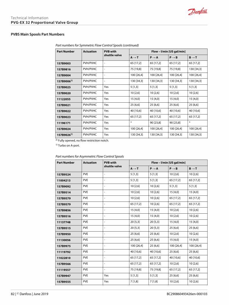
Part numbers for Symmetric Flow Control Spools (continued)
Part Number Actuation PVB withshuttle valve
Flow – l/min [US gal/min]
A → T P → A P → B B → T
157B9003 PVH/PVHC - 65 [17,2] 65 [17,2] 65 [17,2] 65 [17,2]
157B9816 PVH/PVHC - 75 [19,8] 75 [19,8] 75 [19,8] 130 [34,3]
157B9004 PVH/PVHC - 100 [26,4] 100 [26,4] 100 [26,4] 100 [26,4]
157B90061) PVH/PVHC - 130 [34,3] 130 [34,3] 130 [34,3] 130 [34,3]
157B9025 PVH/PVHC Yes 5 [1,3] 5 [1,3] 5 [1,3] 5 [1,3]
157B9020 PVH/PVHC Yes 10 [2,6] 10 [2,6] 10 [2,6] 10 [2,6]
11122055 PVH/PVHC Yes 15 [4,0] 15 [4,0] 15 [4,0] 15 [4,0]
157B9021 PVH/PVHC Yes 25 [6,6] 25 [6,6] 25 [6,6] 25 [6,6]
157B9022 PVH/PVHC Yes 40 [10,6] 40 [10,6] 40 [10,6] 40 [10,6]
157B9023 PVH/PVHC Yes 65 [17,2] 65 [17,2] 65 [17,2] 65 [17,2]
11196171 PVH/PVHC Yes * 90 [23,8] 90 [23,8] *
157B9024 PVH/PVHC Yes 100 [26,4] 100 [26,4] 100 [26,4] 100 [26,4]
157B90261) PVH/PVHC Yes 130 [34,3] 130 [34,3] 130 [34,3] 130 [34,3]
2) Fully opened, no flow restriction notch.1) Turbo on A-port.
Part numbers for Asymmetric Flow Control Spools
Part Number Actuation PVB withshuttle valve
Flow – l/min [US gal/min]
A → T P → A P → B B → T
157B9524 PVE - 5 [1,3] 5 [1,3] 10 [2,6] 10 [2,6]
11004213 PVE - 5 [1,3] 5 [1,3] 65 [17,2] 65 [17,2]
157B9092 PVE - 10 [2,6] 10 [2,6] 5 [1,3] 5 [1,3]
157B9514 PVE - 10 [2,6] 10 [2,6] 15 [4,0] 15 [4,0]
157B9579 PVE - 10 [2,6] 10 [2,6] 65 [17,2] 65 [17,2]
157B9579 PVE - 65 [17,2] 10 [2,6] 65 [17,2] 65 [17,2]
157B9856 PVE - 15 [4,0] 15 [4,0] 10 [2,6] 10 [2,6]
157B9516 PVE - 15 [4,0] 15 [4,0] 10 [2,6] 10 [2,6]
11137748 PVE - 20 [5,3] 20 [5,3] 15 [4,0] 15 [4,0]
157B9515 PVE - 20 [5,3] 20 [5,3] 25 [6,6] 25 [6,6]
157B9950 PVE - 25 [6,6] 25 [6,6] 10 [2,6] 10 [2,6]
11130056 PVE - 25 [6,6] 25 [6,6] 15 [4,0] 15 [4,0]
157B9975 PVE - 100 [26,4] 25 [6,6] 100 [26,4] 100 [26,4]
11119792 PVE - 40 [10,6] 40 [10,6] 25 [6,6] 25 [6,6]
11022810 PVE - 65 [17,2] 65 [17,2] 40 [10,6] 40 [10,6]
157B9566 PVE - 65 [17,2] 65 [17,2] 10 [2,6] 10 [2,6]
11119557 PVE - 75 [19,8] 75 [19,8] 65 [17,2] 65 [17,2]
157B9947 PVE Yes 5 [1,3] 5 [1,3] 25 [6,6] 25 [6,6]
157B9555 PVE Yes 7 [1,8] 7 [1,8] 10 [2,6] 10 [2,6]
Technical InformationPVG-EX 32 Proportional Valve Group
PVBS Main Spools Part Numbers
82 | © Danfoss | June 2019 BC290860493426en-000103
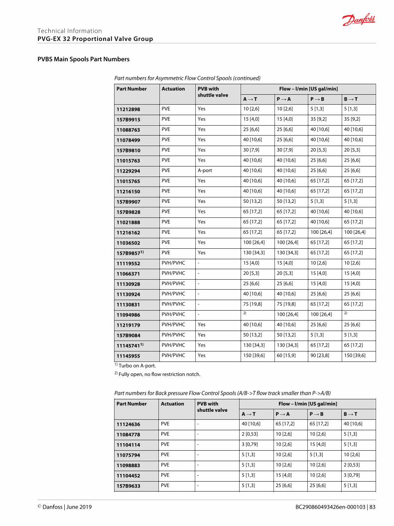
Part numbers for Asymmetric Flow Control Spools (continued)
Part Number Actuation PVB withshuttle valve
Flow – l/min [US gal/min]
A → T P → A P → B B → T
11212898 PVE Yes 10 [2,6] 10 [2,6] 5 [1,3] 5 [1,3]
157B9915 PVE Yes 15 [4,0] 15 [4,0] 35 [9,2] 35 [9,2]
11088763 PVE Yes 25 [6,6] 25 [6,6] 40 [10,6] 40 [10,6]
11078499 PVE Yes 40 [10,6] 25 [6,6] 40 [10,6] 40 [10,6]
157B9810 PVE Yes 30 [7,9] 30 [7,9] 20 [5,3] 20 [5,3]
11015763 PVE Yes 40 [10,6] 40 [10,6] 25 [6,6] 25 [6,6]
11229294 PVE A-port 40 [10,6] 40 [10,6] 25 [6,6] 25 [6,6]
11015765 PVE Yes 40 [10,6] 40 [10,6] 65 [17,2] 65 [17,2]
11216150 PVE Yes 40 [10,6] 40 [10,6] 65 [17,2] 65 [17,2]
157B9907 PVE Yes 50 [13,2] 50 [13,2] 5 [1,3] 5 [1,3]
157B9828 PVE Yes 65 [17,2] 65 [17,2] 40 [10,6] 40 [10,6]
11021888 PVE Yes 65 [17,2] 65 [17,2] 40 [10,6] 65 [17,2]
11216162 PVE Yes 65 [17,2] 65 [17,2] 100 [26,4] 100 [26,4]
11036502 PVE Yes 100 [26,4] 100 [26,4] 65 [17,2] 65 [17,2]
157B98571) PVE Yes 130 [34,3] 130 [34,3] 65 [17,2] 65 [17,2]
11119552 PVH/PVHC - 15 [4,0] 15 [4,0] 10 [2,6] 10 [2,6]
11066371 PVH/PVHC - 20 [5,3] 20 [5,3] 15 [4,0] 15 [4,0]
11130928 PVH/PVHC - 25 [6,6] 25 [6,6] 15 [4,0] 15 [4,0]
11130924 PVH/PVHC - 40 [10,6] 40 [10,6] 25 [6,6] 25 [6,6]
11130831 PVH/PVHC - 75 [19,8] 75 [19,8] 65 [17,2] 65 [17,2]
11094986 PVH/PVHC - 2) 100 [26,4] 100 [26,4] 2)
11219179 PVH/PVHC Yes 40 [10,6] 40 [10,6] 25 [6,6] 25 [6,6]
157B9084 PVH/PVHC Yes 50 [13,2] 50 [13,2] 5 [1,3] 5 [1,3]
111457411) PVH/PVHC Yes 130 [34,3] 130 [34,3] 65 [17,2] 65 [17,2]
11145955 PVH/PVHC Yes 150 [39,6] 60 [15,9] 90 [23,8] 150 [39,6]
1) Turbo on A-port.2) Fully open, no flow restriction notch.
Part numbers for Back pressure Flow Control Spools (A/B->T flow track smaller than P->A/B)
Part Number Actuation PVB withshuttle valve
Flow – l/min [US gal/min]
A → T P → A P → B B → T
11124636 PVE - 40 [10,6] 65 [17,2] 65 [17,2] 40 [10,6]
11084778 PVE - 2 [0,53] 10 [2,6] 10 [2,6] 5 [1,3]
11104114 PVE - 3 [0,79] 10 [2,6] 15 [4,0] 5 [1,3]
11075794 PVE - 5 [1,3] 10 [2,6] 5 [1,3] 10 [2,6]
11098883 PVE - 5 [1,3] 10 [2,6] 10 [2,6] 2 [0,53]
11104452 PVE - 5 [1,3] 15 [4,0] 10 [2,6] 3 [0,79]
157B9633 PVE - 5 [1,3] 25 [6,6] 25 [6,6] 5 [1,3]
Technical InformationPVG-EX 32 Proportional Valve Group
PVBS Main Spools Part Numbers
© Danfoss | June 2019 BC290860493426en-000103 | 83
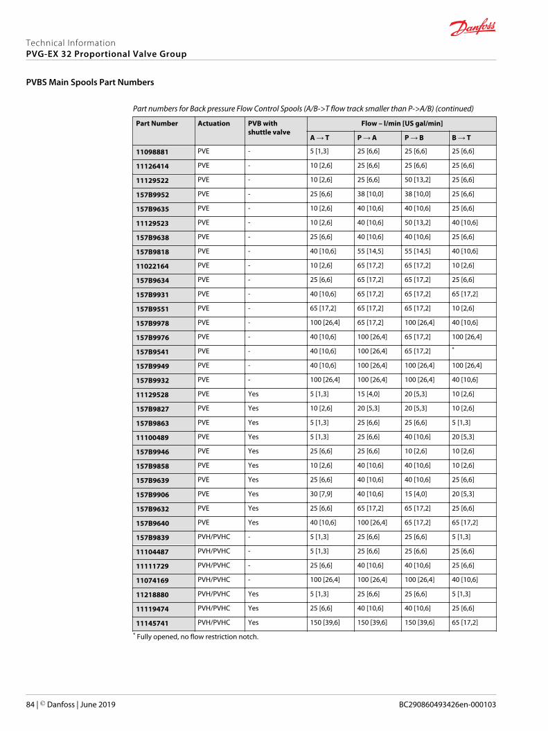
Part numbers for Back pressure Flow Control Spools (A/B->T flow track smaller than P->A/B) (continued)
Part Number Actuation PVB withshuttle valve
Flow – l/min [US gal/min]
A → T P → A P → B B → T
11098881 PVE - 5 [1,3] 25 [6,6] 25 [6,6] 25 [6,6]
11126414 PVE - 10 [2,6] 25 [6,6] 25 [6,6] 25 [6,6]
11129522 PVE - 10 [2,6] 25 [6,6] 50 [13,2] 25 [6,6]
157B9952 PVE - 25 [6,6] 38 [10,0] 38 [10,0] 25 [6,6]
157B9635 PVE - 10 [2,6] 40 [10,6] 40 [10,6] 25 [6,6]
11129523 PVE - 10 [2,6] 40 [10,6] 50 [13,2] 40 [10,6]
157B9638 PVE - 25 [6,6] 40 [10,6] 40 [10,6] 25 [6,6]
157B9818 PVE - 40 [10,6] 55 [14,5] 55 [14,5] 40 [10,6]
11022164 PVE - 10 [2,6] 65 [17,2] 65 [17,2] 10 [2,6]
157B9634 PVE - 25 [6,6] 65 [17,2] 65 [17,2] 25 [6,6]
157B9931 PVE - 40 [10,6] 65 [17,2] 65 [17,2] 65 [17,2]
157B9551 PVE - 65 [17,2] 65 [17,2] 65 [17,2] 10 [2,6]
157B9978 PVE - 100 [26,4] 65 [17,2] 100 [26,4] 40 [10,6]
157B9976 PVE - 40 [10,6] 100 [26,4] 65 [17,2] 100 [26,4]
157B9541 PVE - 40 [10,6] 100 [26,4] 65 [17,2] *
157B9949 PVE - 40 [10,6] 100 [26,4] 100 [26,4] 100 [26,4]
157B9932 PVE - 100 [26,4] 100 [26,4] 100 [26,4] 40 [10,6]
11129528 PVE Yes 5 [1,3] 15 [4,0] 20 [5,3] 10 [2,6]
157B9827 PVE Yes 10 [2,6] 20 [5,3] 20 [5,3] 10 [2,6]
157B9863 PVE Yes 5 [1,3] 25 [6,6] 25 [6,6] 5 [1,3]
11100489 PVE Yes 5 [1,3] 25 [6,6] 40 [10,6] 20 [5,3]
157B9946 PVE Yes 25 [6,6] 25 [6,6] 10 [2,6] 10 [2,6]
157B9858 PVE Yes 10 [2,6] 40 [10,6] 40 [10,6] 10 [2,6]
157B9639 PVE Yes 25 [6,6] 40 [10,6] 40 [10,6] 25 [6,6]
157B9906 PVE Yes 30 [7,9] 40 [10,6] 15 [4,0] 20 [5,3]
157B9632 PVE Yes 25 [6,6] 65 [17,2] 65 [17,2] 25 [6,6]
157B9640 PVE Yes 40 [10,6] 100 [26,4] 65 [17,2] 65 [17,2]
157B9839 PVH/PVHC - 5 [1,3] 25 [6,6] 25 [6,6] 5 [1,3]
11104487 PVH/PVHC - 5 [1,3] 25 [6,6] 25 [6,6] 25 [6,6]
11111729 PVH/PVHC - 25 [6,6] 40 [10,6] 40 [10,6] 25 [6,6]
11074169 PVH/PVHC - 100 [26,4] 100 [26,4] 100 [26,4] 40 [10,6]
11218880 PVH/PVHC Yes 5 [1,3] 25 [6,6] 25 [6,6] 5 [1,3]
11119474 PVH/PVHC Yes 25 [6,6] 40 [10,6] 40 [10,6] 25 [6,6]
11145741 PVH/PVHC Yes 150 [39,6] 150 [39,6] 150 [39,6] 65 [17,2]
* Fully opened, no flow restriction notch.
Technical InformationPVG-EX 32 Proportional Valve Group
PVBS Main Spools Part Numbers
84 | © Danfoss | June 2019 BC290860493426en-000103

Flow Control Spools—Closed Neutral Position with A-float
Schematic for PVBS with shuttle valve
Part numbers for Asymmetric Flow Control Spools
Part Number Actuation PVB withshuttle valve
Flow - l/min [US gal/min]
A → T P → A P → B B → T
11020293 PVE Yes * 100 [26,4] 65 [17,2] ** Fully opened, no flow restriction notch
Technical InformationPVG-EX 32 Proportional Valve Group
PVBS Main Spools Part Numbers
© Danfoss | June 2019 BC290860493426en-000103 | 85

Flow Control Spools—Closed Neutral Position with B-float
Schematic for PVBS with shuttle valve
Part numbers for Symmetric Flow Control Spools
Part Number Actuation PVB withshuttle valve
Flow - l/min [US gal/min]
A → T P → A P → B B → T
157B7620 PVE Yes 10 [2,6] 10 [2,6] 10 [2,6] 10 [2,6]
157B7621 PVE Yes 25 [6,6] 25 [6,6] 25 [6,6] 25 [6,6]
157B7622 PVE Yes 40 [10,6] 40 [10,6] 40 [10,6] 40 [10,6]
157B7623 PVE Yes 65 [17,2] 65 [17,2] 65 [17,2] 65 [17,2]
157B76241 PVE Yes 100 [26,4] 100 [26,4] 100 [26,4] 100 [26,4]
157B9620 PVH/PVHC Yes 10 [2,6] 10 [2,6] 10 [2,6] 10 [2,6]
157B9636 PVH/PVHC Yes 25 [6,6] 25 [6,6] 25 [6,6] 25 [6,6]
11051805 PVH/PVHC Yes 65 [17,2] 65 [17,2] 65 [17,2] 65 [17,2]
110855011 PVH/PVHC Yes 100 [26,4] 100 [26,4] 100 [26,4] 100 [26,4]
1 Turbo on A and B port.
Part numbers for Asymmetric Flow Control Spools
Part Number Actuation PVB withshuttle valve
Flow - l/min [US gal/min]
A → T P → A P → B B → T
157B9911 PVE Yes 30 [7,9] 30 [7,9] 65 [17,2] 65 [17,2]
157B95181 PVE Yes 100 [26,4] 100 [26,4] 65 [17,2] 100 [26,4]
1 Turbo on A port.
Part numbers for Back pressure Flow Control Spools (A/B->T flow track smaller than P->A/B)
Part Number Actuation PVB withshuttle valve
Flow - l/min [US gal/min]
A → T P → A P → B B → T
11129529 PVE Yes 3 [0,8] 10 [2,6] 13 [3,4] 5 [1,3]
157B9691 PVE Yes 15 [4,0] 30 [7,9] 30 [7,9] 15 [4,0]
157B9692 PVE Yes 25 [6,6] 50 [13,2] 65 [17,2] 65 [17,2]
157B99411 PVE Yes 100 [26,4] 130 [34,3] 130 [34,3] 130 [34,3]
157B9691 PVH/PVHC Yes 15 [4,0] 30 [7,9] 30 [7,9] 15 [4,0]
157B9692 PVH/PVHC Yes 25 [6,6] 50 [13,2] 65 [17,2] 65 [17,2]
1 Turbo on A and B port.
Technical InformationPVG-EX 32 Proportional Valve Group
PVBS Main Spools Part Numbers
86 | © Danfoss | June 2019 BC290860493426en-000103

Flow Control Spools—Closed Neutral Position with A-float for PVMF
Schematic for PVBS with shuttle valve
Part numbers for Symmetric Flow Control Spools
Part Number Actuation PVB withshuttle valve
Flow - l/min [US gal/min]
A → T P → A P → B B → T
157B9825 PVE Yes 5 [1,3] 5 [1,3] 5 [1,3] 5 [1,3]
157B9820 PVE Yes 10 [2,6] 10 [2,6] 10 [2,6] 10 [2,6]
157B9821 PVE Yes 25 [6,6] 25 [6,6] 25 [6,6] 25 [6,6]
157B9822 PVE Yes 40 [10,6] 40 [10,6] 40 [10,6] 40 [10,6]
157B9823 PVE Yes 65 [17,2] 65 [17,2] 65 [17,2] 65 [17,2]
157B98241) PVE Yes 100 [26,4] 100 [26,4] 100 [26,4] 100 [26,4]
1) Turbo on A and B port.
Flow Control Spools—Closed Neutral Position with B-float for PVMF
Schematic for PVBS with shuttle valve
Part numbers for Symmetric Flow Control Spools
Part Number Actuation PVB withshuttle valve
Flow - l/min [US gal/min]
A → T P → A P → B B → T
157B9821 PVE Yes 25 [6,6] 25 [6,6] 25 [6,6] 25 [6,6]
157B9822 PVE Yes 40 [10,6] 40 [10,6] 40 [10,6] 40 [10,6]
157B9823 PVE Yes 65 [17,2] 65 [17,2] 65 [17,2] 65 [17,2]
157B98241) PVE Yes 100 [26,4] 100 [26,4] 100 [26,4] 100 [26,4]
1) Turbo on A and B port.
Technical InformationPVG-EX 32 Proportional Valve Group
PVBS Main Spools Part Numbers
© Danfoss | June 2019 BC290860493426en-000103 | 87

Flow Control Spools—Closed Neutral Position for PVMR
Schematic for PVBS without shuttle valve Schematic for PVBS with shuttle valve
Part numbers for Symmetric Flow Control Spools
Part Number Actuation PVB withshuttle valve
Flow – l/min [US gal/min]
A → T P → A P → B B → T
157B9705 PVE - 5 [1,3] 5 [1,3] 5 [1,3] 5 [1,3]
157B9700 PVE - 10 [2,6] 10 [2,6] 10 [2,6] 10 [2,6]
11095634 PVE - 15 [4,0] 15 [4,0] 15 [4,0] 15 [4,0]
157B9701 PVE - 25 [6,6] 25 [6,6] 25 [6,6] 25 [6,6]
157B9702 PVE - 40 [10,6] 40 [10,6] 40 [10,6] 40 [10,6]
157B9703 PVE - 65 [17,2] 65 [17,2] 65 [17,2] 65 [17,2]
157B9704 PVE - 100 [26,4] 100 [26,4] 100 [26,4] 100 [26,4]
157B9725 PVE Yes 5 [1,3] 5 [1,3] 5 [1,3] 5 [1,3]
157B9720 PVE Yes 10 [2,6] 10 [2,6] 10 [2,6] 10 [2,6]
157B9721 PVE Yes 25 [6,6] 25 [6,6] 25 [6,6] 25 [6,6]
157B9722 PVE Yes 40 [10,6] 40 [10,6] 40 [10,6] 40 [10,6]
157B9723 PVE Yes 65 [17,2] 65 [17,2] 65 [17,2] 65 [17,2]
157B9724 PVE Yes 100 [26,4] 100 [26,4] 100 [26,4] 100 [26,4]
Technical InformationPVG-EX 32 Proportional Valve Group
PVBS Main Spools Part Numbers
88 | © Danfoss | June 2019 BC290860493426en-000103

Flow Control Spools—Open/Closed Neutral Position
Schematic for PVBS without shuttle valve Schematic for PVBS with shuttle valve
Part numbers for Symmetric Flow Control Spools
Part Number Actuation PVB withshuttle valve
Flow – l/min [US gal/min]
A → T P → A P → B B → T
157B7101 PVE - 25 [6,6] 25 [6,6] 25 [6,6] 25 [6,6]
157B9537 PVE - 40 [10,6] 40 [10,6] 40 [10,6] 65 [10,6]
157B7103 PVE - 65 [17,2] 65 [17,2] 65 [17,2] 65 [17,2]
11100878 PVE Yes 35 [9,2] 35 [9,2] 35 [9,2] 35 [9,2]
11027254 PVE Yes 75 [19,8] 75 [19,8] 75 [19,8] 75 [19,8]
Part numbers for Asymmetric Flow Control Spools
Part Number Actuation PVB withshuttle valve
Flow – l/min [US gal/min]
A → T P → A P → B B → T
157B9698 PVE Yes 15 [4,0] 15 [4,0] 10 [2,6] 10 [2,6]
11055532 PVE Yes 35 [9,2] 35 [9,2] 65 [17,2] 65 [17,2]
11025812 PVE Yes 50 [13,2] 50 [13,2] 75 [19,8] 75 [19,8]
Back pressure Flow Control Spools (A/B->T flow track smaller than P->A/B)
Part Number Actuation PVB withshuttle valve
Flow – l/min [US gal/min]
A → T P → A P → B B → T
11094317 PVE Yes 2 [0,5] 5 [1,3] 5 [1,3] 2 [0,5]
11051992 PVE Yes 5 [1,3] 18 [4,8] 18 [4,8] 5 [1,3]
11027284 PVE Yes 6 [1,6] 25 [6,6] 25 [6,6] 6 [1,6]
11117573 PVE Yes 25 [6,6] 35 [9,2] 65 [17,2] 65 [17,2]
11025212 PVE Yes 35 [9,2] 35 [9,2] 18 [4,8] 12 [3,2]
11137744 PVE Yes 35 [9,2] 50 [13,2] 75 [19,8] 75 [19,8]
11027911 PVE Yes 65 [17,2] 65 [17,2] 35 [9,2] 25 [6,6]
11027922 PVE Yes 75 [19,8] 75 [19,8] 50 [13,2] 35 [9,2]
Flow Control Spools—Open/Closed A and Closed B Position
Schematic for PVBS with shuttle valve
Technical InformationPVG-EX 32 Proportional Valve Group
PVBS Main Spools Part Numbers
© Danfoss | June 2019 BC290860493426en-000103 | 89

Part numbers for Symmetric Flow Control Spools
Part Number Actuation PVB withshuttle valve
Flow – l/min [US gal/min]
A → T P → A P → B B → T
11213583 PVE Yes 100 [26.4] 100 [26.4] 100 [26.4] 100 [26.4]
Part numbers for Asymmetric Flow Control Spools
Part Number Actuation PVB withshuttle valve
Flow – l/min [US gal/min]
A → T P → A P → B B → T
11201798 PVE Yes 100 [26.4] 100 [26.4] 65 [17.2] 65 [17.2]
Technical InformationPVG-EX 32 Proportional Valve Group
PVBS Main Spools Part Numbers
90 | © Danfoss | June 2019 BC290860493426en-000103

Flow Control Spools—Throttled Open Neutral Position
Schematic for PVBS without shuttle valve Schematic for PVBS with shuttle valve
Part numbers for Symmetric Flow Control Spools
Part Number Actuation PVB withshuttle valve
Flow – l/min [US gal/min]
A → T P → A P → B B → T
157B9697 PVE - 1 [0,26] 1 [0,26] 1 [0,26] 1 [0,26]
157B7105 PVE - 5 [1,3] 5 [1,3] 5 [1,3] 5 [1,3]
157B7100 PVE - 10 [2,6] 10 [2,6] 10 [2,6] 10 [2,6]
157B7101 PVE - 25 [6,6] 25 [6,6] 25 [6,6] 25 [6,6]
157B9534 PVE - 25 [6,6] 25 [6,6] 25 [6,6] 40 [6,6]
157B7102 PVE - 40 [10,6] 40 [10,6] 40 [10,6] 40 [10,6]
157B9537 PVE - 40 [10,6] 40 [10,6] 40 [10,6] 65 [10,6]
11091340 PVE - 3) 40 [10,6] 40 [10,6] 3)
157B9521 PVE - 3) 40 [10,6] 40 [10,6] 3)
157B9677 PVE - 50 [13,2] 50 [13,2] 50 [13,2] 50 [13,2]
157B7103 PVE - 65 [17,2] 65 [17,2] 65 [17,2] 65 [17,2]
11007176 PVE - 3) 65 [17,2] 65 [17,2] 3)
11122809 PVE - 75 [19,8] 75 [19,8] 75 [19,8] 75 [19,8]
157B7104 PVE - 100 [26,4] 100 [26,4] 100 [26,4] 100 [26,4]
11144269 PVE - 100 [26,4] 100 [26,4] 100 [26,4] 3)
157B90982) PVE - 130 [34,3] 130 [34,3] 130 [34,3] 130 [34,3]
157B71061) PVE - 130 [34,3] 130 [34,3] 130 [34,3] 130 [34,3]
157B9675 PVE Yes 3 [0,8] 3 [0,8] 3 [0,8] 3 [0,8]
157B7125 PVE Yes 5 [1,3] 5 [1,3] 5 [1,3] 5 [1,3]
157B7120 PVE Yes 10 [2,6] 10 [2,6] 10 [2,6] 10 [2,6]
157B9647 PVE Yes 15 [4,0] 15 [4,0] 15 [4,0] 15 [4,0]
157B9594 PVE Yes 20 [5,3] 20 [5,3] 20 [5,3] 20 [5,3]
157B7121 PVE Yes 25 [6,6] 25 [6,6] 25 [6,6] 25 [6,6]
11029379 PVE Yes 25 [6,6] 25 [6,6] 25 [6,6] 25 [6,6]
11153790 PVE Yes 3) 25 [6,6] 25 [6,6] 3)
157B7122 PVE Yes 40 [10,6] 40 [10,6] 40 [10,6] 40 [10,6]
157B9538 PVE Yes 40 [10,6] 40 [10,6] 40 [10,6] 40 [10,6]
11121691 PVE Yes 65 [17,2] 65 [17,2] 65 [17,2] 65 [17,2]
11108808 PVE Yes 100 [26,4] 100 [26,4] 100 [26,4] 100 [26,4]
157B9649 PVE Yes 55 [14,5] 55 [14,5] 55 [14,5] 55 [14,5]
157B7123 PVE Yes 65 [17,2] 65 [17,2] 65 [17,2] 65 [17,2]
157B9650 PVE Yes 75 [19,8] 75 [19,8] 75 [19,8] 75 [19,8]
11217660 PVE Yes * 90 90 *
Technical InformationPVG-EX 32 Proportional Valve Group
PVBS Main Spools Part Numbers
© Danfoss | June 2019 BC290860493426en-000103 | 91

Part numbers for Symmetric Flow Control Spools (continued)
Part Number Actuation PVB withshuttle valve
Flow – l/min [US gal/min]
A → T P → A P → B B → T
157B99302) PVE Yes 100 [26,4] 100 [26,4] 100 [26,4] 100 [26,4]
157B7124 PVE Yes 100 [26,4] 100 [26,4] 100 [26,4] 100 [26,4]
11122118 PVE Yes 3) 100 [26,4] 100 [26,4] 3)
111426342) PVE Yes 130 [34,3] 130 [34,3] 130 [34,3] 130 [34,3]
157B71261) PVE Yes 130 [34,3] 130 [34,3] 130 [34,3] 130 [34,3]
157B98541) PVE Yes 130 [34,3] 130 [34,3] 130 [34,3] 3)
157B9105 PVH/PVHC - 5 [1,3] 5 [1,3] 5 [1,3] 5 [1,3]
157B9100 PVH/PVHC - 10 [2,6] 10 [2,6] 10 [2,6] 10 [2,6]
157B9101 PVH/PVHC - 25 [6,6] 25 [6,6] 25 [6,6] 25 [6,6]
157B9102 PVH/PVHC - 40 [10,6] 40 [10,6] 40 [10,6] 40 [10,6]
157B9103 PVH/PVHC - 65 [17,2] 65 [17,2] 65 [17,2] 65 [17,2]
157B9104 PVH/PVHC - 100 [26,4] 100 [26,4] 100 [26,4] 100 [26,4]
157B91061) PVH/PVHC - 130 [34,3] 130 [34,3] 130 [34,3] 130 [34,3]
157B9125 PVH/PVHC Yes 5 [1,3] 5 [1,3] 5 [1,3] 5 [1,3]
157B9120 PVH/PVHC Yes 10 [2,6] 10 [2,6] 10 [2,6] 10 [2,6]
157B9121 PVH/PVHC Yes 25 [6,6] 25 [6,6] 25 [6,6] 25 [6,6]
157B9122 PVH/PVHC Yes 40 [10,6] 40 [10,6] 40 [10,6] 40 [10,6]
157B9123 PVH/PVHC Yes 65 [17,2] 65 [17,2] 65 [17,2] 65 [17,2]
157B91242) PVH/PVHC Yes 100 [26,4] 100 [26,4] 100 [26,4] 100 [26,4]
157B91261) PVH/PVHC Yes 130 [34,3] 130 [34,3] 130 [34,3] 130 [34,3]
11201697 PVH/PVHC Yes 40 40 40 40
3) Fully opened, no flow restriction notch2) Dead band 0.8 mm [0.03 in]1) Turbo on A and B port
Part numbers for Asymmetric Flow Control Spools
Part Number Actuation PVB withshuttle valve
Flow – l/min [US gal/min]
A → T P → A P → B B → T
11004389 PVE - 5 [1,3] 5 [1,3] 65 [17,2] 65 [17,2]
157B9094 PVE - 15 [4,0] 15 [4,0] 30 [7,9] 30 [7,9]
157B9544 PVE - 100 [26,4] 15 [4,0] 25 [6,6] 40 [10,6]
157B9526 PVE - 30 [7,9] 30 [7,9] 15 [4,0] 15 [4,0]
157B9815 PVE - 30 [7,9] 30 [7,9] 20 [5,3] 20 [5,3]
157B9545 PVE - 40 [10,6] 40 [10,6] 15 [4,0] 40 [10,6]
11093116 PVE - 40 [10,6] 40 [10,6] 20 [5,3] 20 [5,3]
11005204 PVE - 40 [10,6] 40 [10,6] 65 [17,2] 65 [17,2]
157B9595 PVE - 40 [10,6] 40 [10,6] 100 [26,4] 100 [26,4]
157B9860 PVE - 50 [13,2] 50 [13,2] 20 [5,3] 20 [5,3]
Technical InformationPVG-EX 32 Proportional Valve Group
PVBS Main Spools Part Numbers
92 | © Danfoss | June 2019 BC290860493426en-000103

Part numbers for Asymmetric Flow Control Spools (continued)
Part Number Actuation PVB withshuttle valve
Flow – l/min [US gal/min]
A → T P → A P → B B → T
11091575 PVE - 55 [14,5] 55 [14,5] 30 [7,9] 30 [7,9]
157B9696 PVE - 65 [17,2] 65 [17,2] 10 [2,6] 10 [2,6]
157B9506 PVE - 65 [17,2] 65 [17,2] 40 [10,6] 40 [10,6]
157B9586 PVE - 65 [17,2] 65 [17,2] 100 [26,4] 100 [26,4]
11137895 PVE - * 65 [17,2] 40 [10,6] *
11122941 PVE Yes 15 [4,0] 15 [4,0] 100 [26,4] 100 [26,4]
157B9830 PVE Yes 25 [6,6] 25 [6,6] 40 [10,6] 40 [10,6]
11070681 PVE Yes 25 [6,6] 25 [6,6] 50 [13,2] 50 [13,2]
11217665 PVE Yes 25 [6,6] 25 [6,6] 100 [26,4] 100 [26,4]
157B9547 PVE Yes 40 [10,6] 25 [6,6] 20 [5,3] 40 [10,6]
157B9558 PVE Yes 30 [7,9] 30 [7,9] 10 [2,6] 10 [2,6]
157B9833 PVE Yes 30 [7,9] 30 [7,9] 20 [5,3] 20 [5,3]
157B9813 PVE Yes 30 [7,9] 30 [7,9] 55 [14,5] 55 [14,5]
11100875 PVE Yes * 35 [9,2] 18 [4,8] *
11100881 PVE Yes * 35 [9,2] 50 [13,2] *
157B9567 PVE Yes 40 [10,6] 40 [10,6] 20 [5,3] 20 [5,3]
157B9865 PVE Yes 40 [10,6] 40 [10,6] 25 [6,6] 25 [6,6]
11125125 PVE Yes 40 [10,6] 40 [10,6] 65 [17,2] 65 [17,2]
157B9505 PVE Yes 40 [10,6] 40 [10,6] 100 [26,4] 100 [26,4]
11096423 PVE Yes 50 [13,2] 50 [13,2] 65 [17,2] 65 [17,2]
157B9681 PVE Yes 55 [14,5] 55 [14,5] 30 [7,9] 30 [7,9]
157B9814 PVE Yes 65 [17,2] 65 [17,2] 40 [10,6] 40 [10,6]
11217660 PVE Yes 1 80 [21,1] 80 [21,1] 1
11202615 PVH/PVHC - 25 [6,6] 25 [6,6] 25 [6,6] 40 [10,6]
157B9847 PVH/PVHC - 30 [7,9] 30 [7,9] 20 [5,3] 20 [5,3]
157B9546 PVH/PVHC - 40 [10,6] 25 [6,6] 20 [5,3] 40 [10,6]
157B9686 PVH/PVHC - 40 [10,6] 30 [7,9] 25 [6,6] 40 [10,6]
157B9685 PVH/PVHC - 40 [10,6] 40 [10,6] 35 [9,2] 40 [10,6]
157B9498 PVH/PVHC - 65 [17,2] 65 [17,2] 40 [10,6] 40 [10,6]
11140120 PVH/PVHC - * 65 [17,2] 65 [17,2] *
157B9688 PVH/PVHC - 100 [26,4] 20 [5,3] 30 [7,9] 40 [10,6]
11079579 PVH/PVHC Yes 25 [6,6] 25 [6,6] 50 [13,2] 50 [13,2]
11218879 PVH/PVHC Yes 40 [10,6] 40 [10,6] 15 [4.0] 15 [4.0]
157B9689 PVH/PVHC Yes 40 [10,6] 30 [7,9] 30 [7,9] 40 [10,6]
11200936 PVH/PVHC Yes 40 [10,6] 40 [10,6] 25 [6,6] 25 [6,6]
11092123 PVH/PVHC Yes 40 [10,6] 40 [10,6] 100 [26,4] 100 [26,4]
11147574 PVH/PVHC Yes * 65 [17,2] 65 [17,2] *
Technical InformationPVG-EX 32 Proportional Valve Group
PVBS Main Spools Part Numbers
© Danfoss | June 2019 BC290860493426en-000103 | 93

Part numbers for Asymmetric Flow Control Spools (continued)
Part Number Actuation PVB withshuttle valve
Flow – l/min [US gal/min]
A → T P → A P → B B → T
11200922 PVH/PVHC Yes 65 [17,2] 65 [17,2] 40 [10,6] 40 [10,6]
11153474 PVH/PVHC Yes 80 [21,1] 80 [21,1] 65 [17,2] 65 [17,2]
* Fully opened, no flow restriction notch1 Fully open, no flow restriction notch
Back pressure Flow Control Spools (A/B->T flow track smaller than P->A/B)
Part Number Actuation PVB withshuttle valve
Flow – l/min [US gal/min]
A → T P → A P → B B → T
11034321 PVE - 3 [0,79] 3 [0,79] 10 [2,6] 1 [0,26]
11074918 PVE - 5 [1,3] 10 [2,6] 5 [1,3] 10 [2,6]
11006879 PVE - 25 [6,6] 25 [6,6] 65 [17,2] 25 [6,6]
11097891 PVE Yes 40 [10,6] 100 [26,4] 40 [10,6] 40 [10,6]
157B9684 PVH/PVHC - 25 [6,6] 30 [7,9] 30 [7,9] 25 [6,6]
157B9687 PVH/PVHC - 25 [6,6] 35 [9,2] 35 [9,2] 25 [6,6]
Technical InformationPVG-EX 32 Proportional Valve Group
PVBS Main Spools Part Numbers
94 | © Danfoss | June 2019 BC290860493426en-000103

Flow Control Spools—Throttled Open Neutral Position for PVMR
Schematic for PVBS without shuttle valve Schematic for PVBS with shuttle valve
Part numbers for Symmetric Flow Control Spools
Part Number Actuation PVB withshuttle valve
Flow – l/min [US gal/min]
A → T P → A P → B B → T
157B9715 PVE - 5 [1,3] 5 [1,3] 5 [1,3] 5 [1,3]
157B9710 PVE - 10 [2,6] 10 [2,6] 10 [2,6] 10 [2,6]
157B9711 PVE - 25 [6,6] 25 [6,6] 25 [6,6] 25 [6,6]
157B9712 PVE - 40 [10,6] 40 [10,6] 40 [10,6] 40 [10,6]
157B9678 PVE - 50 [13,2] 50 [13,2] 50 [13,2] 50 [13,2]
157B9713 PVE - 65 [17,2] 65 [17,2] 65 [17,2] 65 [17,2]
11128430 PVE - 80 [21,1] 80 [21,1] 80 [21,1] 80 [21,1]
157B9714 PVE - 100 [26,4] 100 [26,4] 100 [26,4] 100 [26,4]
157B97161) PVE - 130 [34,3] 130 [34,3] 130 [34,3] 130 [34,3]
157B9735 PVE Yes 5 [1,3] 5 [1,3] 5 [1,3] 5 [1,3]
157B9730 PVE Yes 10 [2,6] 10 [2,6] 10 [2,6] 10 [2,6]
157B9731 PVE Yes 25 [6,6] 25 [6,6] 25 [6,6] 25 [6,6]
157B9732 PVE Yes 40 [10,6] 40 [10,6] 40 [10,6] 40 [10,6]
157B9733 PVE Yes 65 [17,2] 65 [17,2] 65 [17,2] 65 [17,2]
157B9734 PVE Yes 100 [26,4] 100 [26,4] 100 [26,4] 100 [26,4]
1) Turbo on A and B port
Part numbers for Asymmetric Flow Control Spools
Part Number Actuation PVB withshuttle valve
Flow – l/min [US gal/min]
A → T P → A P → B B → T
11107125 PVE - 5 [1,3] 5 [1,3] 65 [17,2] 65 [17,2]
11119504 PVE - 40 [10,6] 40 [10,6] 65 [17,2] 65 [17,2]
11071543 PVE Yes 30 [7,9] 30 [7,9] 10 [2,6] 10 [2,6]
Technical InformationPVG-EX 32 Proportional Valve Group
PVBS Main Spools Part Numbers
© Danfoss | June 2019 BC290860493426en-000103 | 95

Flow Control Spools—Throttled A to T Neutral Position
Schematic for PVBS without shuttle valve Schematic for PVBS with shuttle valve
Part numbers for Symmetric Flow Control Spools
Part Number Actuation PVB withshuttle valve
Flow – l/min [US gal/min]
A → T P → A P → B B → T
157B9504 PVE - 15 [4,0] 15 [4,0] 15 [4,0] 15 [4,0]
157B7401 PVE - 25 [6,6] 25 [6,6] 25 [6,6] 25 [6,6]
157B7402 PVE - 40 [10,6] 40 [10,6] 40 [10,6] 40 [10,6]
157B7403 PVE - 65 [17,2] 65 [17,2] 65 [17,2] 65 [17,2]
157B7404 PVE - 100 [26,4] 100 [26,4] 100 [26,4] 100 [26,4]
157B74061) PVE - 130 [34,3] 130 [34,3] 130 [34,3] 130 [34,3]
157B9846 PVE - 2) 130 [34,3] 130 [34,3] 130 [34,3]
157B9527 PVE Yes 15 [4,0] 15 [4,0] 15 [4,0] 15 [4,0]
157B7421 PVE Yes 25 [6,6] 25 [6,6] 25 [6,6] 25 [6,6]
157B7422 PVE Yes 40 [10,6] 40 [10,6] 40 [10,6] 40 [10,6]
157B7423 PVE Yes 65 [17,2] 65 [17,2] 65 [17,2] 65 [17,2]
157B7424 PVE Yes 100 [26,4] 100 [26,4] 100 [26,4] 100 [26,4]
157B7404 PVH/PVHC - 100 [26,4] 100 [26,4] 100 [26,4] 100 [26,4]
157B7424 PVH/PVHC Yes 100 [26,4] 100 [26,4] 100 [26,4] 100 [26,4]
1) Turbo on A and B port.2) Fully opened, no flow restriction notch.
Part numbers for Asymmetric Flow Control Spools
Part Number Actuation PVB withshuttle valve
Flow – l/min [US gal/min]
A → T P → A P → B B → T
11022518 PVE - 25 [6,6] 25 [6,6] 40 [10,6] 40 [10,6]
157B9834 PVE - 30 [7,9] 30 [7,9] 20 [5,3] 20 [5,3]
11202228 PVE - 100 [26,4] 100 [26,4] 100 [26,4] 100 [26,4]
11201797 PVE Yes 150 [39.6] 150 [39.6] 100 [26,4] 100 [26,4]
Technical InformationPVG-EX 32 Proportional Valve Group
PVBS Main Spools Part Numbers
96 | © Danfoss | June 2019 BC290860493426en-000103
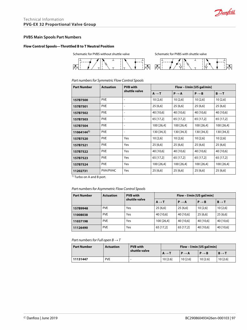
Flow Control Spools—Throttled B to T Neutral Position
Schematic for PVBS without shuttle valve Schematic for PVBS with shuttle valve
Part numbers for Symmetric Flow Control Spools
Part Number Actuation PVB withshuttle valve
Flow – l/min [US gal/min]
A → T P → A P → B B → T
157B7500 PVE - 10 [2,6] 10 [2,6] 10 [2,6] 10 [2,6]
157B7501 PVE - 25 [6,6] 25 [6,6] 25 [6,6] 25 [6,6]
157B7502 PVE - 40 [10,6] 40 [10,6] 40 [10,6] 40 [10,6]
157B7503 PVE - 65 [17,2] 65 [17,2] 65 [17,2] 65 [17,2]
157B7504 PVE - 100 [26,4] 100 [26,4] 100 [26,4] 100 [26,4]
110641441) PVE - 130 [34,3] 130 [34,3] 130 [34,3] 130 [34,3]
157B7520 PVE Yes 10 [2,6] 10 [2,6] 10 [2,6] 10 [2,6]
157B7521 PVE Yes 25 [6,6] 25 [6,6] 25 [6,6] 25 [6,6]
157B7522 PVE Yes 40 [10,6] 40 [10,6] 40 [10,6] 40 [10,6]
157B7523 PVE Yes 65 [17,2] 65 [17,2] 65 [17,2] 65 [17,2]
157B7524 PVE Yes 100 [26,4] 100 [26,4] 100 [26,4] 100 [26,4]
11202731 PVH/PVHC Yes 25 [6,6] 25 [6,6] 25 [6,6] 25 [6,6]
1) Turbo on A and B port.
Part numbers for Asymmetric Flow Control Spools
Part Number Actuation PVB withshuttle valve
Flow – l/min [US gal/min]
A → T P → A P → B B → T
157B9948 PVE Yes 25 [6,6] 25 [6,6] 10 [2,6] 10 [2,6]
11008038 PVE Yes 40 [10,6] 40 [10,6] 25 [6,6] 25 [6,6]
11037198 PVE Yes 100 [26,4] 40 [10,6] 40 [10,6] 40 [10,6]
11126490 PVE Yes 65 [17,2] 65 [17,2] 40 [10,6] 40 [10,6]
Part numbers for Full open B → T
Part Number Actuation PVB withshuttle valve
Flow – l/min [US gal/min]
A → T P → A P → B B → T
11131447 PVE - 10 [2.6] 10 [2.6] 10 [2.6] 10 [2.6]
Technical InformationPVG-EX 32 Proportional Valve Group
PVBS Main Spools Part Numbers
© Danfoss | June 2019 BC290860493426en-000103 | 97

Linear Flow Control Spools—Closed Neutral Position
Schematic for PVBS without shuttle valve Schematic for PVBS with shuttle valve
Part numbers for Symmetric Flow Control Spools
Part Number Actuation PVB withshuttle valve
Flow – l/min [US gal/min]
A → T P → A P → B B → T
11231130 PVE - 65 [17,2] 65 [17,2] 65 [17,2] 65 [17,2]
157B9770 PVE Yes 10 [2,6] 10 [2,6] 10 [2,6] 10 [2,6]
157B9771 PVE Yes 25 [6,6] 25 [6,6] 25 [6,6] 25 [6,6]
157B95111) PVE Yes 25 [6,6] 25 [6,6] 25 [6,6] 25 [6,6]
157B9772 PVE Yes 40 [10,6] 40 [10,6] 40 [10,6] 40 [10,6]
157B9773 PVE Yes 65 [17,2] 65 [17,2] 65 [17,2] 65 [17,2]
157B96551) PVE Yes 85 [17,2] 85 [17,2] 85 [17,2] 85 [17,2]
11073991 PVH/PVHC - 40 [10,6] 40 [10,6] 40 [10,6] 40 [10,6]
11051903 PVH/PVHC - 100 [26,4] 100 [26,4] 100 [26,4] 100 [26,4]
11107159 PVH/PVHC Yes 10 [2,6] 10 [2,6] 10 [2,6] 10 [2,6]
11107222 PVH/PVHC Yes 40 [10,6] 40 [10,6] 40 [10,6] 40 [10,6]
157B9080 PVH/PVHC Yes 65 [17,2] 65 [17,2] 65 [17,2] 65 [17,2]
11083650 PVH/PVHC Yes 2) 85 [17,2] 85 [17,2] 2)
1) Dead band 1,1 mm [0,04 in].2) Fully opened, no flow restriction notch.
Part numbers for Asymmetric Flow Control Spools
Part Number Actuation PVB withshuttle valve
Flow – l/min [US gal/min]
A → T P → A P → B B → T
157B9086 PVH/PVHC - 65 [17,2] 65 [17,2] 100 [26,4] 100 [26,4]
Dead band 1,5 mm [0,06 in].
Part number for Back pressure Flow Control Spools (A/B->T flow track smaller than P->A/B)
Part Number Actuation PVB withshuttle valve
Flow – l/min [US gal/min]
A → T P → A P → B B → T
11151485 PVE Yes 30 [7.9] 85 [22.5] 110 [29,1] 35 [9.2]
Dead band 0.8 mm [0,03 in].
Technical InformationPVG-EX 32 Proportional Valve Group
PVBS Main Spools Part Numbers
98 | © Danfoss | June 2019 BC290860493426en-000103

Linear Flow Control Spools—Throttled Open Neutral Position
Schematic for PVBS without shuttle valve Schematic for PVBS with shuttle valve
Part numbers for Symmetric Flow Control Spools
Part Number Actuation PVB withshuttle valve
Flow – l/min [US gal/min]
A → T P → A P → B B → T
11140460 PVE Yes 5 [1,3] 5 [1,3] 5 [1,3] 5 [1,3]
157B9780 PVE Yes 10 [2,6] 10 [2,6] 10 [2,6] 10 [2,6]
157B9781 PVE Yes 25 [6,6] 25 [6,6] 25 [6,6] 25 [6,6]
157B9782 PVE Yes 40 [10,6] 40 [10,6] 40 [10,6] 40 [10,6]
11076654 PVE Yes 50 [13,2] 50 [13,2] 50 [13,2] 50 [13,2]
157B9783 PVE Yes 65 [17,2] 65 [17,2] 65 [17,2] 65 [17,2]
157B9784 PVE Yes 100 [26,4] 100 [26,4] 100 [26,4] 100 [26,4]
157B9577* PVE Yes 130 [34,3] 130 [34,3] 130 [34,3] 130 [34,3]
157B9807 PVH/PVHC - 10 [2,6] 10 [2,6] 10 [2,6] 10 [2,6]
157B9805 PVH/PVHC - 25 [6,6] 25 [6,6] 25 [6,6] 25 [6,6]
11046738 PVH/PVHC - 40 [10,6] 40 [10,6] 40 [10,6] 40 [10,6]
11080984 PVH/PVHC - 65 [17,2] 65 [17,2] 65 [17,2] 65 [17,2]
11153567 PVH/PVHC - 100 [26,4] 40 [10,6] 40 [10,6] 100 [26,4]
112182481) PVH/PVHC - 130 [34,3] 130 [34,3] 130 [34,3] 130 [34,3]
157B9806 PVH/PVHC Yes 25 [6,6] 25 [6,6] 25 [6,6] 25 [6,6]
157B9079 PVH/PVHC Yes 40 [10,6] 40 [10,6] 40 [10,6] 40 [10,6]
157B9081 PVH/PVHC Yes 65 [17,2] 65 [17,2] 65 [17,2] 65 [17,2]
157B9082 PVH/PVHC Yes 100 [26,4] 100 [26,4] 100 [26,4] 100 [26,4]
11140180 PVH/PVHC Yes 2) 100 [26,4] 100 [26,4] 2)
11231448 PVE - 40 [10,6] 40 [10,6] 40 [10,6] 40 [10,6]
11216148 PVE - * 55 [14,5] 55 [14,5] *
11231449 PVE - 100 [26,4] 100 [26,4] 100 [26,4] 100 [26,4]
* Turbo on A and B port
Part numbers for Assymmetric Flow Control Spools
Part Number Actuation PVB withshuttle valve
Flow – l/min [US gal/min]
A → T P → A P → B B → T
112018301) PVH/PVHC - 2) 65 [17,2] 65 [17,2] 2)
1) Dead band 0.8 mm [0,03 in].2) Fully opened, no flow restriction notch
Technical InformationPVG-EX 32 Proportional Valve Group
PVBS Main Spools Part Numbers
© Danfoss | June 2019 BC290860493426en-000103 | 99

Linear Flow Control Spools—Open/Closed Neutral Position
Schematic for PVBS without shuttle valve Schematic for PVBS with shuttle valve
Part numbers for Back pressure Flow Control Spools (A/B->T flow track smaller than P->A/B)
Part Number Actuation PVB withshuttle valve
Flow – l/min [US gal/min]
A → T P → A P → B B → T
11146795 PVE Yes 15 [4.0] 40 [10.6] 65 [17.2] 15 [4.0]
11146797 PVE Yes 15 [4.0] 65 [17.2] 40 [10.6] 10 [2.6]
11151486* PVE Yes 20 [5.3] 80 [21.1] 110 [29,1] 40 [10.6]
* Dead band 0.8 mm [0,03 in].
Single Acting Cylinder Flow Control Spools—Neutral A-port Position
Schematic for PVBS without shuttle valve
Symmetric flow control spools
Part Number Actuation PVB withshuttle valve
Flow – l/min [US gal/min]
A → T P → A P → B B → T
11077423 PVE - 5 [1,3] 5 [1,3] - -
157B7200 PVE - 10 [2,6] 10 [2,6] - -
157B7201 PVE - 25 [6,6] 25 [6,6] - -
157B7202 PVE - 40 [10,6] 40 [10,6] - -
157B7203 PVE - 65 [17,2] 65 [17,2] - -
157B7204 PVE - 100 [26,4] 100 [26,4] - -
11015830 PVE - 130 [34,3] 130 [34,3] - -
157B9200 PVH/PVHC - 10 [2,6] 10 [2,6] - -
157B9201 PVH/PVHC - 25 [6,6] 25 [6,6] - -
157B9202 PVH/PVHC - 40 [10,6] 40 [10,6] - -
157B9203 PVH/PVHC - 65 [17,2] 65 [17,2] - -
157B9204 PVH/PVHC - 100 [26,4] 100 [26,4] - -
11085447 PVH/PVHC - 130 [34,3] 130 [34,3] - -
Back pressure Flow Control Spool (A/B->T flow track smaller than P->A/B)
Part Number Actuation PVB withshuttle valve
Flow – l/min [US gal/min]
A → T P → A P → B B → T
157B9905 PVE - 25 [6.6] 65 [17.2] - -
Technical InformationPVG-EX 32 Proportional Valve Group
PVBS Main Spools Part Numbers
100 | © Danfoss | June 2019 BC290860493426en-000103

Single Acting Cylinder Flow Control Spools—Neutral B-port Position
Schematic for PVBS without shuttle valve
Symmetric flow control spools
Part Number Actuation PVB withshuttle valve
Flow – l/min [US gal/min]
A → T P → A P → B B → T
157B7300 PVE - - - 10 [2,6] 10 [2,6]
157B7301 PVE - - - 25 [6,6] 25 [6,6]
157B7302 PVE - - - 40 [10,6] 40 [10,6]
157B7303 PVE - - - 65 [17,2] 65 [17,2]
157B7304 PVE - - - 100 [26,4] 100 [26,4]
157B9301 PVH/PVHC - - - 25 [6,6] 25 [6,6]
Back pressure Flow Control Spool (A/B->T flow track smaller than P->A/B)
Part Number Actuation PVB withshuttle valve
Flow – l/min [US gal/min]
A → T P → A P → B B → T
157B9912 PVE - - - 65 [17,2] 25 [6,6]
11098878 PVE - - - 25 [6,6] 5 [1,3]
11104486 PVH/PVHC - - - 25 [6,6] 5 [1,3]
Single Acting Cylinder Linear Flow Control Spools—Neutral B-port Position
Schematic for PVBS without shuttle valve
Back pressure Flow Control Spool (A/B->T flow track smaller than P->A/B)
Part Number Actuation PVB withshuttle valve
Flow – l/min [US gal/min]
A → T P → A P → B B → T
157B9668 PVE - - - 65 [17,2] 40 [10,6]
Technical InformationPVG-EX 32 Proportional Valve Group
PVBS Main Spools Part Numbers
© Danfoss | June 2019 BC290860493426en-000103 | 101
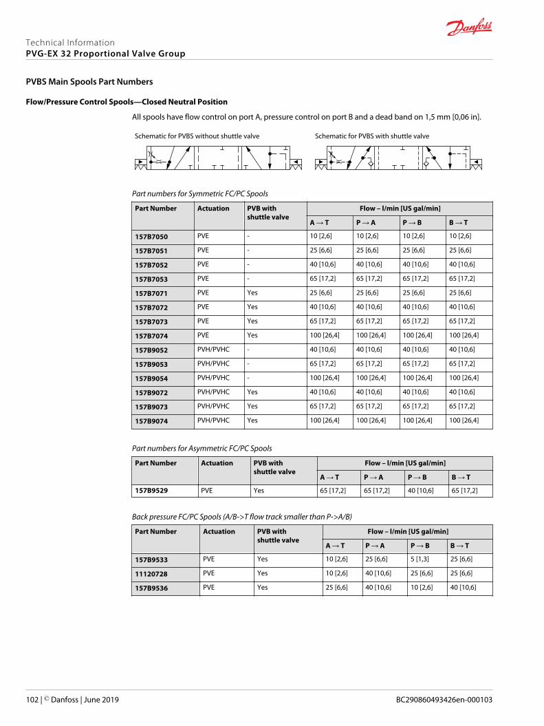
Flow/Pressure Control Spools—Closed Neutral Position
All spools have flow control on port A, pressure control on port B and a dead band on 1,5 mm [0,06 in].
Schematic for PVBS without shuttle valve Schematic for PVBS with shuttle valve
Part numbers for Symmetric FC/PC Spools
Part Number Actuation PVB withshuttle valve
Flow – l/min [US gal/min]
A → T P → A P → B B → T
157B7050 PVE - 10 [2,6] 10 [2,6] 10 [2,6] 10 [2,6]
157B7051 PVE - 25 [6,6] 25 [6,6] 25 [6,6] 25 [6,6]
157B7052 PVE - 40 [10,6] 40 [10,6] 40 [10,6] 40 [10,6]
157B7053 PVE - 65 [17,2] 65 [17,2] 65 [17,2] 65 [17,2]
157B7071 PVE Yes 25 [6,6] 25 [6,6] 25 [6,6] 25 [6,6]
157B7072 PVE Yes 40 [10,6] 40 [10,6] 40 [10,6] 40 [10,6]
157B7073 PVE Yes 65 [17,2] 65 [17,2] 65 [17,2] 65 [17,2]
157B7074 PVE Yes 100 [26,4] 100 [26,4] 100 [26,4] 100 [26,4]
157B9052 PVH/PVHC - 40 [10,6] 40 [10,6] 40 [10,6] 40 [10,6]
157B9053 PVH/PVHC - 65 [17,2] 65 [17,2] 65 [17,2] 65 [17,2]
157B9054 PVH/PVHC - 100 [26,4] 100 [26,4] 100 [26,4] 100 [26,4]
157B9072 PVH/PVHC Yes 40 [10,6] 40 [10,6] 40 [10,6] 40 [10,6]
157B9073 PVH/PVHC Yes 65 [17,2] 65 [17,2] 65 [17,2] 65 [17,2]
157B9074 PVH/PVHC Yes 100 [26,4] 100 [26,4] 100 [26,4] 100 [26,4]
Part numbers for Asymmetric FC/PC Spools
Part Number Actuation PVB withshuttle valve
Flow – l/min [US gal/min]
A → T P → A P → B B → T
157B9529 PVE Yes 65 [17,2] 65 [17,2] 40 [10,6] 65 [17,2]
Back pressure FC/PC Spools (A/B->T flow track smaller than P->A/B)
Part Number Actuation PVB withshuttle valve
Flow – l/min [US gal/min]
A → T P → A P → B B → T
157B9533 PVE Yes 10 [2,6] 25 [6,6] 5 [1,3] 25 [6,6]
11120728 PVE Yes 10 [2,6] 40 [10,6] 25 [6,6] 25 [6,6]
157B9536 PVE Yes 25 [6,6] 40 [10,6] 10 [2,6] 40 [10,6]
Technical InformationPVG-EX 32 Proportional Valve Group
PVBS Main Spools Part Numbers
102 | © Danfoss | June 2019 BC290860493426en-000103
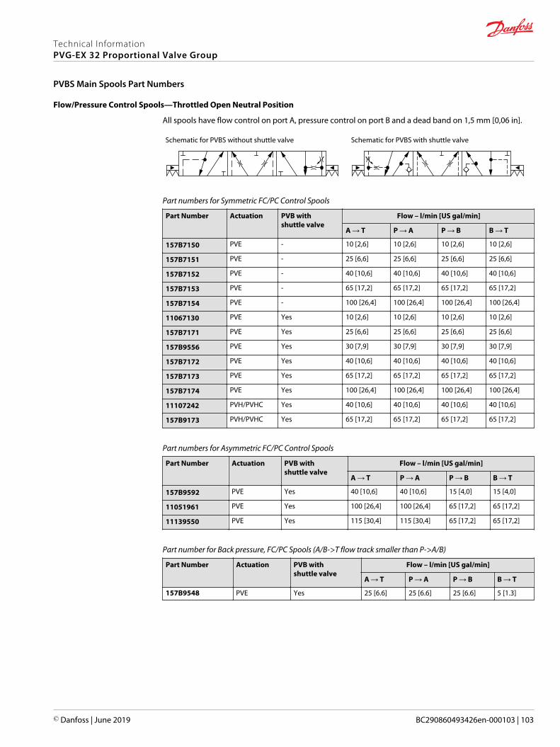
Flow/Pressure Control Spools—Throttled Open Neutral Position
All spools have flow control on port A, pressure control on port B and a dead band on 1,5 mm [0,06 in].
Schematic for PVBS without shuttle valve Schematic for PVBS with shuttle valve
Part numbers for Symmetric FC/PC Control Spools
Part Number Actuation PVB withshuttle valve
Flow – l/min [US gal/min]
A → T P → A P → B B → T
157B7150 PVE - 10 [2,6] 10 [2,6] 10 [2,6] 10 [2,6]
157B7151 PVE - 25 [6,6] 25 [6,6] 25 [6,6] 25 [6,6]
157B7152 PVE - 40 [10,6] 40 [10,6] 40 [10,6] 40 [10,6]
157B7153 PVE - 65 [17,2] 65 [17,2] 65 [17,2] 65 [17,2]
157B7154 PVE - 100 [26,4] 100 [26,4] 100 [26,4] 100 [26,4]
11067130 PVE Yes 10 [2,6] 10 [2,6] 10 [2,6] 10 [2,6]
157B7171 PVE Yes 25 [6,6] 25 [6,6] 25 [6,6] 25 [6,6]
157B9556 PVE Yes 30 [7,9] 30 [7,9] 30 [7,9] 30 [7,9]
157B7172 PVE Yes 40 [10,6] 40 [10,6] 40 [10,6] 40 [10,6]
157B7173 PVE Yes 65 [17,2] 65 [17,2] 65 [17,2] 65 [17,2]
157B7174 PVE Yes 100 [26,4] 100 [26,4] 100 [26,4] 100 [26,4]
11107242 PVH/PVHC Yes 40 [10,6] 40 [10,6] 40 [10,6] 40 [10,6]
157B9173 PVH/PVHC Yes 65 [17,2] 65 [17,2] 65 [17,2] 65 [17,2]
Part numbers for Asymmetric FC/PC Control Spools
Part Number Actuation PVB withshuttle valve
Flow – l/min [US gal/min]
A → T P → A P → B B → T
157B9592 PVE Yes 40 [10,6] 40 [10,6] 15 [4,0] 15 [4,0]
11051961 PVE Yes 100 [26,4] 100 [26,4] 65 [17,2] 65 [17,2]
11139550 PVE Yes 115 [30,4] 115 [30,4] 65 [17,2] 65 [17,2]
Part number for Back pressure, FC/PC Spools (A/B->T flow track smaller than P->A/B)
Part Number Actuation PVB withshuttle valve
Flow – l/min [US gal/min]
A → T P → A P → B B → T
157B9548 PVE Yes 25 [6.6] 25 [6.6] 25 [6.6] 5 [1.3]
Technical InformationPVG-EX 32 Proportional Valve Group
PVBS Main Spools Part Numbers
© Danfoss | June 2019 BC290860493426en-000103 | 103
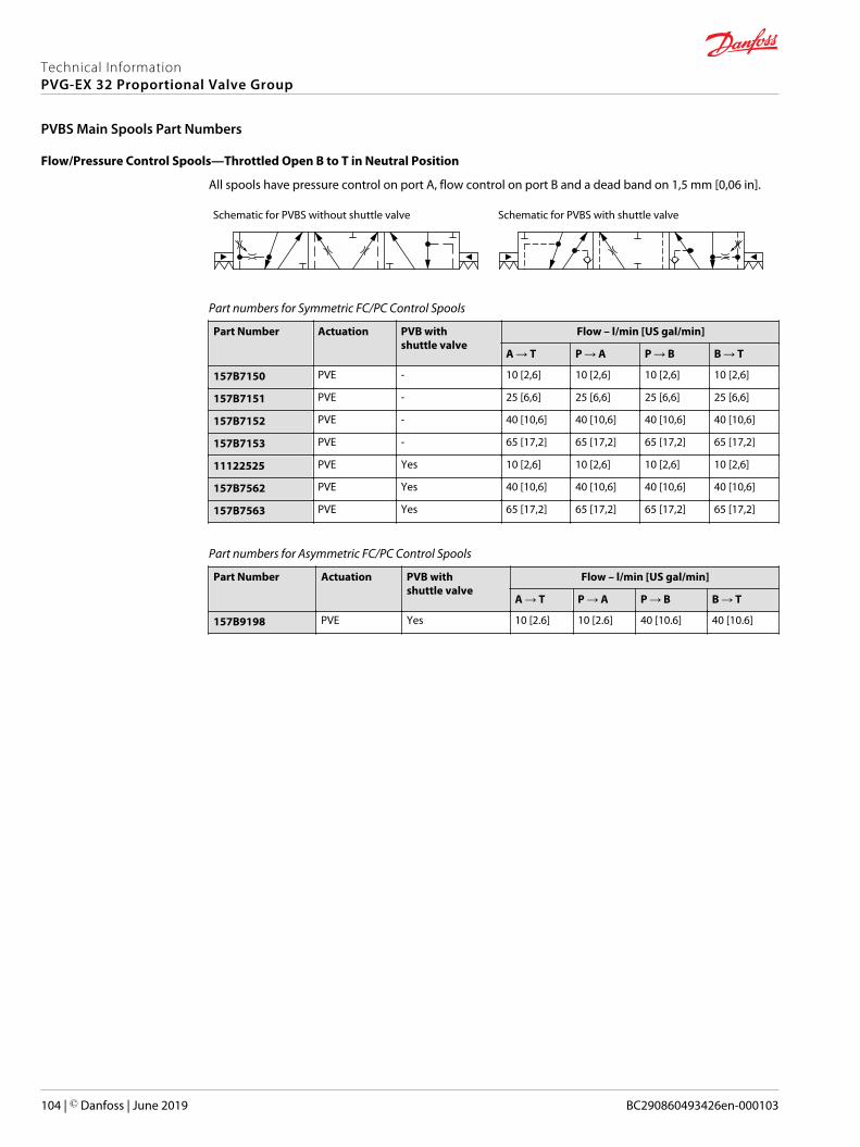
Flow/Pressure Control Spools—Throttled Open B to T in Neutral Position
All spools have pressure control on port A, flow control on port B and a dead band on 1,5 mm [0,06 in].
Schematic for PVBS without shuttle valve Schematic for PVBS with shuttle valve
Part numbers for Symmetric FC/PC Control Spools
Part Number Actuation PVB withshuttle valve
Flow – l/min [US gal/min]
A → T P → A P → B B → T
157B7150 PVE - 10 [2,6] 10 [2,6] 10 [2,6] 10 [2,6]
157B7151 PVE - 25 [6,6] 25 [6,6] 25 [6,6] 25 [6,6]
157B7152 PVE - 40 [10,6] 40 [10,6] 40 [10,6] 40 [10,6]
157B7153 PVE - 65 [17,2] 65 [17,2] 65 [17,2] 65 [17,2]
11122525 PVE Yes 10 [2,6] 10 [2,6] 10 [2,6] 10 [2,6]
157B7562 PVE Yes 40 [10,6] 40 [10,6] 40 [10,6] 40 [10,6]
157B7563 PVE Yes 65 [17,2] 65 [17,2] 65 [17,2] 65 [17,2]
Part numbers for Asymmetric FC/PC Control Spools
Part Number Actuation PVB withshuttle valve
Flow – l/min [US gal/min]
A → T P → A P → B B → T
157B9198 PVE Yes 10 [2.6] 10 [2.6] 40 [10.6] 40 [10.6]
Technical InformationPVG-EX 32 Proportional Valve Group
PVBS Main Spools Part Numbers
104 | © Danfoss | June 2019 BC290860493426en-000103
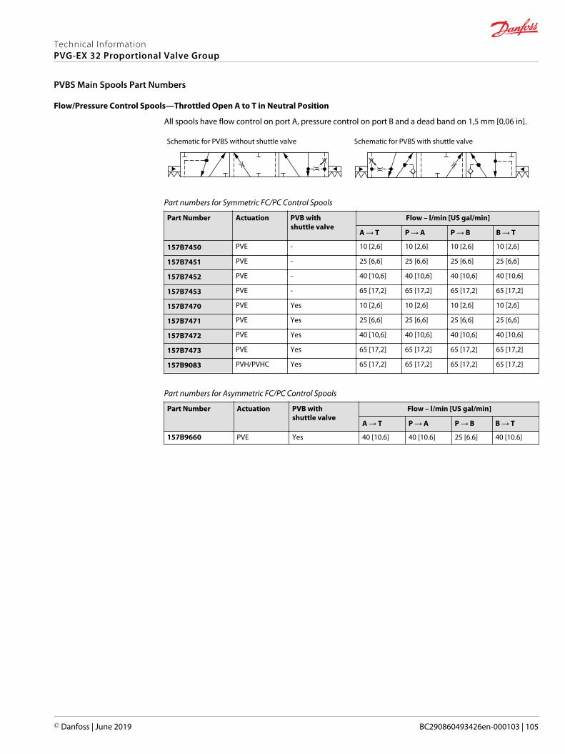
Flow/Pressure Control Spools—Throttled Open A to T in Neutral Position
All spools have flow control on port A, pressure control on port B and a dead band on 1,5 mm [0,06 in].
Schematic for PVBS without shuttle valve Schematic for PVBS with shuttle valve
Part numbers for Symmetric FC/PC Control Spools
Part Number Actuation PVB withshuttle valve
Flow – l/min [US gal/min]
A → T P → A P → B B → T
157B7450 PVE - 10 [2,6] 10 [2,6] 10 [2,6] 10 [2,6]
157B7451 PVE - 25 [6,6] 25 [6,6] 25 [6,6] 25 [6,6]
157B7452 PVE - 40 [10,6] 40 [10,6] 40 [10,6] 40 [10,6]
157B7453 PVE - 65 [17,2] 65 [17,2] 65 [17,2] 65 [17,2]
157B7470 PVE Yes 10 [2,6] 10 [2,6] 10 [2,6] 10 [2,6]
157B7471 PVE Yes 25 [6,6] 25 [6,6] 25 [6,6] 25 [6,6]
157B7472 PVE Yes 40 [10,6] 40 [10,6] 40 [10,6] 40 [10,6]
157B7473 PVE Yes 65 [17,2] 65 [17,2] 65 [17,2] 65 [17,2]
157B9083 PVH/PVHC Yes 65 [17,2] 65 [17,2] 65 [17,2] 65 [17,2]
Part numbers for Asymmetric FC/PC Control Spools
Part Number Actuation PVB withshuttle valve
Flow – l/min [US gal/min]
A → T P → A P → B B → T
157B9660 PVE Yes 40 [10.6] 40 [10.6] 25 [6.6] 40 [10.6]
Technical InformationPVG-EX 32 Proportional Valve Group
PVBS Main Spools Part Numbers
© Danfoss | June 2019 BC290860493426en-000103 | 105

Flow/Pressure Control Spools—Throttled Open B to T in Neutral Position
All spools have flow control on port A, pressure control on port B and a dead band on 1,5 mm [0,06 in].
Schematic for PVBS without shuttle valve Schematic for PVBS with shuttle valve
Part numbers for Asymmetric FC/PC Control Spools
Part Number Actuation PVB withshuttle valve
Flow – l/min [US gal/min]
A → T P → A P → B B → T
157B9591 PVE - 40 [10,6] 40 [10,6] 25 [6,6] 40 [10,6]
157B9641 PVE - 50 [13,2] 50 [13,2] 10 [2,6] 10 [2,6]
157B9660 PVE Yes 50 [13,2] 50 [13,2] 10 [2,6] 10 [2,6]
157B9832 PVE Yes 55 [14,5] 55 [14,5] 25 [6,6] 25 [6,6]
Flow/Pressure Control Spools—Open/Closed in Neutral Position
All spools have flow control on port A, pressure control on port B and a dead band on 1,0 mm [0,04 in].
Schematic for PVBS without shuttle valve
Part number for Back pressure FC/PC Spools (A/B->T flow track smaller than P->A/B)
Part Number Actuation PVB withshuttle valve
Flow – l/min [US gal/min]
A → T P → A P → B B → T
11067514 PVE — 40 [10.6] 40 [10.6] 25 [6.6] 25 [6.6]
Flow/Pressure Control Spools—Closed A and Open/Closed B Position
Schematic for PVBS with shuttle valve
Part numbers for Symmetric FC/PC Flow Control Spools
Part Number Actuation PVB withshuttle valve
Flow – l/min [US gal/min]
A → T P → A P → B B → T
11213570 PVE Yes 40 [10.6] 40 [10.6] 40 [10.6] 40 [10.6]
Technical InformationPVG-EX 32 Proportional Valve Group
PVBS Main Spools Part Numbers
106 | © Danfoss | June 2019 BC290860493426en-000103
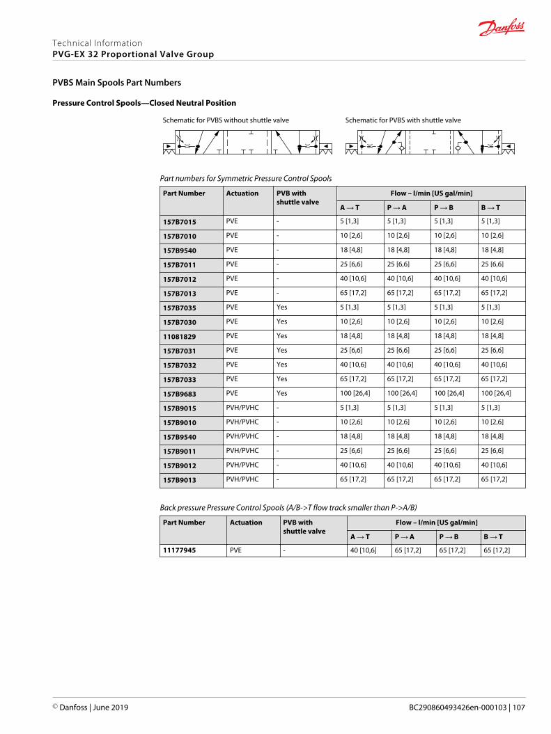
Pressure Control Spools—Closed Neutral Position
Schematic for PVBS without shuttle valve Schematic for PVBS with shuttle valve
Part numbers for Symmetric Pressure Control Spools
Part Number Actuation PVB withshuttle valve
Flow – l/min [US gal/min]
A → T P → A P → B B → T
157B7015 PVE - 5 [1,3] 5 [1,3] 5 [1,3] 5 [1,3]
157B7010 PVE - 10 [2,6] 10 [2,6] 10 [2,6] 10 [2,6]
157B9540 PVE - 18 [4,8] 18 [4,8] 18 [4,8] 18 [4,8]
157B7011 PVE - 25 [6,6] 25 [6,6] 25 [6,6] 25 [6,6]
157B7012 PVE - 40 [10,6] 40 [10,6] 40 [10,6] 40 [10,6]
157B7013 PVE - 65 [17,2] 65 [17,2] 65 [17,2] 65 [17,2]
157B7035 PVE Yes 5 [1,3] 5 [1,3] 5 [1,3] 5 [1,3]
157B7030 PVE Yes 10 [2,6] 10 [2,6] 10 [2,6] 10 [2,6]
11081829 PVE Yes 18 [4,8] 18 [4,8] 18 [4,8] 18 [4,8]
157B7031 PVE Yes 25 [6,6] 25 [6,6] 25 [6,6] 25 [6,6]
157B7032 PVE Yes 40 [10,6] 40 [10,6] 40 [10,6] 40 [10,6]
157B7033 PVE Yes 65 [17,2] 65 [17,2] 65 [17,2] 65 [17,2]
157B9683 PVE Yes 100 [26,4] 100 [26,4] 100 [26,4] 100 [26,4]
157B9015 PVH/PVHC - 5 [1,3] 5 [1,3] 5 [1,3] 5 [1,3]
157B9010 PVH/PVHC - 10 [2,6] 10 [2,6] 10 [2,6] 10 [2,6]
157B9540 PVH/PVHC - 18 [4,8] 18 [4,8] 18 [4,8] 18 [4,8]
157B9011 PVH/PVHC - 25 [6,6] 25 [6,6] 25 [6,6] 25 [6,6]
157B9012 PVH/PVHC - 40 [10,6] 40 [10,6] 40 [10,6] 40 [10,6]
157B9013 PVH/PVHC - 65 [17,2] 65 [17,2] 65 [17,2] 65 [17,2]
Back pressure Pressure Control Spools (A/B->T flow track smaller than P->A/B)
Part Number Actuation PVB withshuttle valve
Flow – l/min [US gal/min]
A → T P → A P → B B → T
11177945 PVE - 40 [10,6] 65 [17,2] 65 [17,2] 65 [17,2]
Technical InformationPVG-EX 32 Proportional Valve Group
PVBS Main Spools Part Numbers
© Danfoss | June 2019 BC290860493426en-000103 | 107

Pressure Control Spools—Throttled Open Neutral Position
All spools have pressure control on port A and B and a dead band on 1,5 mm [0,06 in].
Schematic for PVBS without shuttle valve Schematic for PVBS with shuttle valve
Part numbers for Symmetric Pressure Control Spools
Part Number Actuation PVB withshuttle valve
Flow – l/min [US gal/min]
A → T P → A P → B B → T
157B7115 PVE - 5 [1,3] 5 [1,3] 5 [1,3] 5 [1,3]
157B7110 PVE - 10 [2,6] 10 [2,6] 10 [2,6] 10 [2,6]
157B7111 PVE - 25 [6,6] 25 [6,6] 25 [6,6] 25 [6,6]
157B7112 PVE - 40 [10,6] 40 [10,6] 40 [10,6] 40 [10,6]
157B7113 PVE - 65 [17,2] 65 [17,2] 65 [17,2] 65 [17,2]
157B9853 PVE Yes 3 [0,8] 3 [0,8] 3 [0,8] 3 [0,8]
157B7135 PVE Yes 5 [1,3] 5 [1,3] 5 [1,3] 5 [1,3]
157B7130 PVE Yes 10 [2,6] 10 [2,6] 10 [2,6] 10 [2,6]
157B7131 PVE Yes 25 [6,6] 25 [6,6] 25 [6,6] 25 [6,6]
157B7132 PVE Yes 40 [10,6] 40 [10,6] 40 [10,6] 40 [10,6]
157B7133 PVE Yes 65 [17,2] 65 [17,2] 65 [17,2] 65 [17,2]
157B7134 PVE Yes 100 [26,4] 100 [26,4] 100 [26,4] 100 [26,4]
11057575 PVH/PVHC - 5 [1,3] 5 [1,3] 5 [1,3] 5 [1,3]
157B9110 PVH/PVHC - 10 [2,6] 10 [2,6] 10 [2,6] 10 [2,6]
157B9112 PVH/PVHC - 40 [10,6] 40 [10,6] 40 [10,6] 40 [10,6]
157B9113 PVH/PVHC - 65 [17,2] 65 [17,2] 65 [17,2] 65 [17,2]
11057314 PVH/PVHC Yes 5 [1,3] 5 [1,3] 5 [1,3] 5 [1,3]
157B9130 PVH/PVHC Yes 10 [2,6] 10 [2,6] 10 [2,6] 10 [2,6]
157B9131 PVH/PVHC Yes 25 [6,6] 25 [6,6] 25 [6,6] 25 [6,6]
Part numbers for Asymmetric Pressure Control Spools
Part Number Actuation PVB withshuttle valve
Flow – l/min [US gal/min]
A → T P → A P → B B → T
157B9525 PVE - 20 [5,3] 20 [5,3] 10 [2,6] 10 [2,6]
11041330 PVE - 40 [10,6] 40 [10,6] 20 [5,3] 20 [5,3]
157B9634 PVH/PVHC Yes 10 [2,6] 10 [2,6] 5 [1,3] 5 [1,3]
Technical InformationPVG-EX 32 Proportional Valve Group
PVBS Main Spools Part Numbers
108 | © Danfoss | June 2019 BC290860493426en-000103

Pressure Control Spools—Throttled A to T in Neutral Position
Schematic for PVBS with shuttle valve
Part numbers for Pressure Control Spools Throttled A to T in Neutral Position
Part Number Actuation PVB withshuttle valve
Flow – l/min [US gal/min]
A → T P → A P → B B → T
157B9646 PVE Yes 15 [4] 15 [4] 15 [4] 15 [4]
157B9199 PVE Yes 10 [2.6] 10 [2.6] 40 [10.6] 40 [10.6]
Technical InformationPVG-EX 32 Proportional Valve Group
PVBS Main Spools Part Numbers
© Danfoss | June 2019 BC290860493426en-000103 | 109

Pressure/Flow Control Spools—Closed Neutral Position
All spools have pressure control on port A, flow control on port B and a dead band on 1,5 mm [0,06 in].
Schematic for PVBS without shuttle valve Schematic for PVBS with shuttle valve
Part numbers for Symmetric PC/FC Spools
Part Number Actuation PVB withshuttle valve
Flow – l/min [US gal/min]
A → T P → A P → B B → T
157B7040 PVE - 10 [2,6] 10 [2,6] 10 [2,6] 10 [2,6]
157B7041 PVE - 25 [6,6] 25 [6,6] 25 [6,6] 25 [6,6]
157B7042 PVE - 40 [10,6] 40 [10,6] 40 [10,6] 40 [10,6]
157B7043 PVE - 65 [17,2] 65 [17,2] 65 [17,2] 65 [17,2]
157B7044 PVE - 100 [26,4] 100 [26,4] 100 [26,4] 100 [26,4]
157B7061 PVE Yes 25 [6,6] 25 [6,6] 25 [6,6] 25 [6,6]
157B7062 PVE Yes 40 [10,6] 40 [10,6] 40 [10,6] 40 [10,6]
157B7063 PVE Yes 65 [17,2] 65 [17,2] 65 [17,2] 65 [17,2]
157B7064 PVE Yes 100 [26,4] 100 [26,4] 100 [26,4] 100 [26,4]
157B9040 PVH/PVHC - 10 [2,6] 10 [2,6] 10 [2,6] 10 [2,6]
157B9041 PVH/PVHC - 25 [6,6] 25 [6,6] 25 [6,6] 25 [6,6]
157B9042 PVH/PVHC - 40 [10,6] 40 [10,6] 40 [10,6] 40 [10,6]
157B9043 PVH/PVHC - 65 [17,2] 65 [17,2] 65 [17,2] 65 [17,2]
157B9044 PVH/PVHC - 100 [26,4] 100 [26,4] 100 [26,4] 100 [26,4]
157B9062 PVH/PVHC Yes 40 [10,6] 40 [10,6] 40 [10,6] 40 [10,6]
157B9063 PVH/PVHC Yes 65 [17,2] 65 [17,2] 65 [17,2] 65 [17,2]
Part numbers for Asymmetric PC/FC Spools
Part Number Actuation PVB withshuttle valve
Flow – l/min [US gal/min]
A → T P → A P → B B → T
157B9589 PVE Yes 25 [6.6] 25 [6.6] 40 [10,6] 40 [10,6]
157B9528 PVE Yes 65 [17,2] 40 [10,6] 65 [17,2] 65 [17,2]
11223873 PVE Yes 65 [17,2] 40 [10,6] 65 [17,2] 40 [10,6]
Back pressure PC/FC Spools (A/B->T flow track smaller than P->A/B)
Part Number Actuation PVB withshuttle valve
Flow – l/min [US gal/min]
A → T P → A P → B B → T
157B9532 PVE Yes 25 [6,6] 65 [17,2] 25 [6,6] 10 [2,6]
11051179 PVE Yes 25 [6,6] 10 [2,6] 25 [6,6] 5 [1,3]
157B9535 PVE Yes 40 [10,6] 10 [2,6] 40 [10,6] 25 [6,6]
11051177 PVE Yes 25 [6,6] 25 [6,6] 40 [10,6] 10 [2,6]
Technical InformationPVG-EX 32 Proportional Valve Group
PVBS Main Spools Part Numbers
110 | © Danfoss | June 2019 BC290860493426en-000103

Pressure/Flow Control Spools—Closed Neutral Position with B-float
All spools have pressure control on port A, flow control on port B and a dead band on 1,5 mm [0,06 in].
Schematic for PVBS without shuttle valve
Part number for Symmetric PC/FC Spools
Part Number Actuation PVB withshuttle valve
Flow – l/min [US gal/min]
A → T P → A P → B B → T
157B9637 PVE — 10 [2.6] 10 [2.6] 10 [2.6] 10 [2.6]
Pressure/Flow Control Spools—Throttled Open Neutral Position
All spools have pressure control on port A, flow control on port B and a dead band on 1,5 mm [0,06 in].
Schematic for PVBS without shuttle valve Schematic for PVBS with shuttle valve
Part numbers for Symmetric PC/FC Control Spools
Part Number Actuation PVB withshuttle valve
Flow – l/min [US gal/min]
A → T P → A P → B B → T
11122564 PVE - 10 [2,6] 10 [2,6] 10 [2,6] 10 [2,6]
157B7141 PVE - 25 [6,6] 25 [6,6] 25 [6,6] 25 [6,6]
157B7142 PVE - 40 [10,6] 40 [10,6] 40 [10,6] 40 [10,6]
157B7143 PVE - 65 [17,2] 65 [17,2] 65 [17,2] 65 [17,2]
157B7144 PVE - 100 [26,4] 100 [26,4] 100 [26,4] 100 [26,4]
157B7161 PVE Yes 25 [6,6] 25 [6,6] 25 [6,6] 25 [6,6]
157B7162 PVE Yes 40 [10,6] 40 [10,6] 40 [10,6] 40 [10,6]
157B7163 PVE Yes 65 [17,2] 65 [17,2] 65 [17,2] 65 [17,2]
157B7164 PVE Yes 100 [26,4] 100 [26,4] 100 [26,4] 100 [26,4]
157B9163 PVH/PVHC Yes 65 [17,2] 65 [17,2] 65 [17,2] 65 [17,2]
Part numbers for Asymmetric PC/FC Control Spools
Part Number Actuation PVB withshuttle valve
Flow – l/min [US gal/min]
A → T P → A P → B B → T
157B9811 PVE Yes 10 [2,6] 10 [2,6] 40 [10,6] 65 [17,2]
157B9988 PVE Yes 25 [6,6] 10 [2,6] 25 [6,6] 25 [6,6]
Technical InformationPVG-EX 32 Proportional Valve Group
PVBS Main Spools Part Numbers
© Danfoss | June 2019 BC290860493426en-000103 | 111

Pressure/Flow Control Spools—Open/Closed Neutral Position
Schematic for PVBS without shuttle valve
Part number for PC/FC Spool Open/Closed in Neutral Position
Part Number Actuation PVB withshuttle valve
Flow – l/min [US gal/min]
A → T P → A P → B B → T
11104931 PVE — 40 [10.6] 40 [10.6] 40 [10.6] 40 [10.6]
Pressure/Flow Control Spools—Open/Closed A and Closed B Position
Schematic for PVBS with shuttle valve
Part numbers for Symmetric PC/FC Control Spools
Part Number Actuation PVB withshuttle valve
Flow – l/min [US gal/min]
A → T P → A P → B B → T
11213571 PVE Yes 40 [10.6] 40 [10.6] 40 [10.6] 40 [10.6]
11198095 PVE Yes 65 [17.2] 65 [17.2] 65 [17.2] 65 [17.2]
Technical InformationPVG-EX 32 Proportional Valve Group
PVBS Main Spools Part Numbers
112 | © Danfoss | June 2019 BC290860493426en-000103

PVBZ Flow Control Spools—Closed Neutral Position
Schematic for PVBZ without shuttle valve Schematic for PVBZ with shuttle valve
Part numbers for Symmetric Flow Control Spools
Part Number Actuation PVB withshuttle valve
Flow – l/min [US gal/min]
A → T P → A P → B B → T
157B9405 PVE - 5 [1,3] 5 [1,3] 5 [1,3] 5 [1,3]
157B9400 PVE - 10 [2,6] 10 [2,6] 10 [2,6] 10 [2,6]
157B9401 PVE - 25 [6,6] 25 [6,6] 25 [6,6] 25 [6,6]
157B9402 PVE - 40 [10,6] 40 [10,6] 40 [10,6] 40 [10,6]
157B9403 PVE - 65 [17,2] 65 [17,2] 65 [17,2] 65 [17,2]
157B9404 PVE - 100 [26,4] 100 [26,4] 100 [26,4] 100 [26,4]
11051945 PVE Yes 5 [1,3] 5 [1,3] 5 [1,3] 5 [1,3]
11019630 PVE Yes 10 [2,6] 10 [2,6] 10 [2,6] 10 [2,6]
11019631 PVE Yes 25 [6,6] 25 [6,6] 25 [6,6] 25 [6,6]
11019633 PVE Yes 40 [10,6] 40 [10,6] 40 [10,6] 40 [10,6]
11019634 PVE Yes 65 [17,2] 65 [17,2] 65 [17,2] 65 [17,2]
11019635 PVE Yes 100 [26,4] 100 [26,4] 100 [26,4] 100 [26,4]
11105665 PVH/PVHC - 5 [1,3] 5 [1,3] 5 [1,3] 5 [1,3]
11105445 PVH/PVHC - 10 [2,6] 10 [2,6] 10 [2,6] 10 [2,6]
11105446 PVH/PVHC - 25 [6,6] 25 [6,6] 25 [6,6] 25 [6,6]
11125900 PVH/PVHC - 100 [26,4] 100 [26,4] 100 [26,4] 100 [26,4]
11140563 PVH/PVHC Yes 25 [6,6] 25 [6,6] 25 [6,6] 25 [6,6]
11140564 PVH/PVHC Yes 65 [17,2] 65 [17,2] 65 [17,2] 65 [17,2]
Part numbers for Back pressure Flow Control Spools (A/B->T flow track smaller than P->A/B)
Part Number Actuation PVB withshuttle valve
Flow – l/min [US gal/min]
A → T P → A P → B B → T
157B9573* PVH/PVHC - 38 [10,0] 25 [6,6] 65 [17,2] 15 [4,0]
157B9651 PVE - 38 [10,0] 25 [6,6] 65 [17,2] 15 [4,0]
11084227 PVE Yes 5 [1,3] 25 [6,6] 25 [6,6] 25 [6,6]
11129527 PVE Yes 40 [10,6] 10 [2,6] 40 [10,6] 10 [2,6]
11085297 PVE Yes 20 [5,2] 40 [10,6] 40 [10,6] 10 [2,6]
* Deadband 1,5 mm [0,06].
Technical InformationPVG-EX 32 Proportional Valve Group
PVBS for PVBZ Main Spools Part Numbers
© Danfoss | June 2019 BC290860493426en-000103 | 113

PVBZ Flow Control Spools—Closed Neutral Position with A-float
Schematic for PVBZ with shuttle valve
Part numbers for Symmetric Flow Control Spools
Part Number Actuation PVB withshuttle valve
Flow – l/min [US gal/min]
A → T P → A P → B B → T
157B9415 PVE Yes 5 [1,3] 5 [1,3] 5 [1,3] 5 [1,3]
157B9410 PVE Yes 10 [2,6] 10 [2,6] 10 [2,6] 10 [2,6]
157B9411 PVE Yes 25 [6,6] 25 [6,6] 25 [6,6] 25 [6,6]
157B9412 PVE Yes 40 [10,6] 40 [10,6] 40 [10,6] 40 [10,6]
157B9413 PVE Yes 65 [17,2] 65 [17,2] 65 [17,2] 65 [17,2]
157B9414 PVE Yes 100 [26,4] 100 [26,4] 100 [26,4] 100 [26,4]
11027130 PVH/PVHC Yes 25 [6,6] 25 [6,6] 25 [6,6] 25 [6,6]
11124250 PVH/PVHC Yes 100 [26,4] 100 [26,4] 100 [26,4] 100 [26,4]
Part numbers for Back pressure Flow Control Spools (A/B->T flow track smaller than P->A/B)
Part Number Actuation PVB withshuttle valve
Flow – l/min [US gal/min]
A → T P → A P → B B → T
11085128 PVE Yes 2 [0,5] 10 [2,6] 10 [2,6] 5 [1,3]
Part number Flow Control Spools for PVML
Part Number Actuation PVB withshuttle valve
Flow – l/min [US gal/min]
A → T P → A P → B B → T
11128843 PVE Yes 40 [10,6] 40 [10,6] 40 [10,6] 40 [10,6]
157B9596 PVE Yes 100 [26,4] 100 [26,4] 100 [26,4] 100 [26,4]
157B9631 PVE Yes 100 [26,4] 100 [26,4] 100 [26,4] 100 [26,4]
11017592 PVE Yes 120 [31,7] 120 [31,7] 120 [31,7] 120 [31,7]
157B94341) PVE Yes 120 [31,7] 120 [31,7] 120 [31,7] 120 [31,7]
1) Dead band 0,8 mm [0,03 in].
Technical InformationPVG-EX 32 Proportional Valve Group
PVBS for PVBZ Main Spools Part Numbers
114 | © Danfoss | June 2019 BC290860493426en-000103

PVBZ Flow Control Spools—Closed Neutral Position with B-float
Schematic for PVBZ with shuttle valve
Part numbers for Symmetric Flow Control Spools
Part Number Actuation PVB withshuttle valve
Flow – l/min [US gal/min]
A → T P → A P → B B → T
11147069 PVE Yes 100 [26.4] 100 [26.4] 100 [26.4] 100 [26.4]
Part number Flow Control Spools for PVML
Part Number Actuation PVB withshuttle valve
Flow – l/min [US gal/min]
A → T P → A P → B B → T
11146502 PVE Yes 100 [26.4] 100 [26.4] 100 [26.4] 100 [26.4]
PVBZ Flow Control Spools—Throttled Open Neutral Position with B-float
Schematic for PVBZ with shuttle valve
Part number for Symmetric Flow Control Spools
Part Number Actuation PVB withshuttle valve
Flow – l/min [US gal/min]
A → T P → A P → B B → T
157B9690 PVE Yes 15 [4] 15 [4] 15 [4] 15 [4]
Part number Flow Control Spools for PVML
Part Number Actuation PVB withshuttle valve
Flow – l/min [US gal/min]
A → T P → A P → B B → T
11146502 PVE Yes 100 [26.4] 100 [26.4] 100 [26.4] 100 [26.4]
Technical InformationPVG-EX 32 Proportional Valve Group
PVBS for PVBZ Main Spools Part Numbers
© Danfoss | June 2019 BC290860493426en-000103 | 115

PVBZ Linear Flow Control Spools—Closed Neutral Position
Schematic for PVBZ without shuttle valve Schematic for PVBZ with shuttle valve
Part numbers for Symmetric Flow Control Spools
Part Number Actuation PVB withshuttle valve
Flow – l/min [US gal/min]
A → T P → A P → B B → T
157B9664 PVE - 25 [6,6] 25 [6,6] 25 [6,6] 25 [6,6]
157B9809 PVE - 80 [21,1] 80 [21,1] 80 [21,1] 80 [21,1]
Part numbers for Asymmetric Flow Control Spools
Part Number Actuation PVB withshuttle valve
Flow – l/min [US gal/min]
A → T P → A P → B B → T
11130939 PVE Yes 25 [6,6] 40 [10,6] 40 [10,6] 25 [6,6]
Part numbers for Flow Control Spools for PVML
Part Number Actuation PVB withshuttle valve
Flow - l/min [US gal/min]
A → T P → A P → B B → T
157B9866 PVE Yes 25 [6,6] 40 [10,6] 40 [10,6] 25 [6,6]
PVBZ Single Acting Cylinder Flow Control Spools—Closed Neutral A-port Position
Schematic for PVBS without shuttle valve
Symmetric flow control spools
Part Number Actuation PVB withshuttle valve
Flow – l/min [US gal/min]
A → T P → A P → B B → T
157B9859 PVE - 25 [6.6] 25 [6.6] - -
Technical InformationPVG-EX 32 Proportional Valve Group
PVBS for PVBZ Main Spools Part Numbers
116 | © Danfoss | June 2019 BC290860493426en-000103
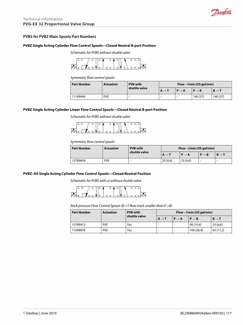
PVBZ Single Acting Cylinder Flow Control Spools—Closed Neutral B-port Position
Schematic for PVBS without shuttle valve
Symmetric flow control spools
Part Number Actuation PVB withshuttle valve
Flow – l/min [US gal/min]
A → T P → A P → B B → T
11149444 PVE - - - 140 [37] 140 [37]
PVBZ Single Acting Cylinder Linear Flow Control Spools—Closed Neutral B-port Position
Schematic for PVBS without shuttle valve
Symmetric flow control spools
Part Number Actuation PVB withshuttle valve
Flow – l/min [US gal/min]
A → T P → A P → B B → T
157B9859 PVE - 25 [6.6] 25 [6.6] - -
PVBZ–HS Single Acting Cylinder Flow Control Spools—Closed Neutral Position
Schematic for PVBS with or without shuttle valve
Back pressure Flow Control Spools (B->T flow track smaller than P->B)
Part Number Actuation PVB withshuttle valve
Flow – l/min [US gal/min]
A → T P → A P → B B → T
157B9912 PVE Yes - - 40 [10,6] 25 [6,6]
11098878 PVE Yes - - 100 [26,4] 65 [17,2]
Technical InformationPVG-EX 32 Proportional Valve Group
PVBS for PVBZ Main Spools Part Numbers
© Danfoss | June 2019 BC290860493426en-000103 | 117
PVG 32 actuation can be done manually, hydraulically, and electrically.
PVG 32 actuation overview:• PVM Manual actuation on page 119• PVMD detention covers on page 121• PVH Hydraulic Actuation on page 122
For information, description and part numbers on electrical EX-actuators please see the followingdocuments:• AN00000349: PVE-EX Installation Guide eb mb version, Group II
• AN00000351: PVE-EX Installation Guide db version, Group I & II
• AN00000365: PVE-EX Installation Guide Aex d version
• BC00000393: PVE-EX Technical Information db version + eb mb version
Technical InformationPVG-EX 32 Proportional Valve Group
PVG-EX 32 Actuation
118 | © Danfoss | June 2019 BC290860493426en-000103

PVM Manual actuation
The PVM variants are based on a generic platform with a selection of additional features, enabling you totailor the PVM to suit the demands of any hydraulic system, which includes the following main variants:• PVM manual actuation or override of a function• Spring centering cover without manual override (PVML)
‒ Optional with lever base
‒ Optional with lever base and lever
‒ Optional flow adjustment screws
The adjustment screws are intended for limiting the spool travel and thereby the maximum achievableflow.
PVM cover PVM dimensions
185.
2 [7
.29]
85 [3
.35]
60 [2.36] 13 [0.51] 44 [1.73]
54.3 [2.14]
Control lever data
No lever position Standard controlrange
Control lever range Control lever range + float position
2 x 6 ± 13.4° ± 19.5° 22.3°
PVM versions torque data
Spool displacement PVM+PVMDPVM+PVE
PVM+PVH PVM+PVMR PVM+PVMF
From neutral position 2.2 ±0.2 N•m[19.5 ±1.8 lb•in]
2.5 ±0.2 N•m[22.1 ± 1.8 lb•in]
17 N•m [3.8 lb•in] 22 N•m [5.0 lb•in]
Max. spool travel 2.8 ±0.2 N•m[24.8 ±1.8 lb•in]
6.9 ±0.2 N•m[61.0 ±1.8 lb•in]
– –
Into float position – – – 60 N•m[13.5 lb•in]
Away from float position – – – 28 N•m [6.3 lb•in]
From any other position – – 8.5 N•m [73.3 lb•in] –
Technical InformationPVG-EX 32 Proportional Valve Group
PVG-EX 32 Actuation
© Danfoss | June 2019 BC290860493426en-000103 | 119

Part number Material Adjustment screws Lever base Lever base and lever Weight
157B3161 Cast iron Yes — Yes 0,4 kg[0,88 lb]
Technical InformationPVG-EX 32 Proportional Valve Group
PVG-EX 32 Actuation
120 | © Danfoss | June 2019 BC290860493426en-000103

PVMD detention covers
The PVMD cover, also referred to as detention cover, is intended for manually activated PVB sections.
PVMD symbol
PVMD detention cover Dimensions, mm [in]
85 [3
.35]
44 [1.73] 17 [0.67]
PVMD Detention Covers detailed information
Technical data
Spool displacement Torque (dependent on spool)
From neutral position PVM+PVMD 2,2±0,2 N·m [19,5±1,8 lbf·in]
Max. spool travel PVM+PVMD 2,8±0,2 N·m [24,8±1,8 lbf·in]
Part numbers for PVMD/F/R covers
Part number Type Material
157B0021 PVMD Cast iron
Technical InformationPVG-EX 32 Proportional Valve Group
PVG-EX 32 Actuation
© Danfoss | June 2019 BC290860493426en-000103 | 121

PVH Hydraulic Actuation
PVH cover PVH 32 cover dimensions
85 [3
.35]
27 [1
.06]
31.5
[1.2
4]
22 [0.87]
33 [1.3]44 [1.73]
The hydraulic remote control lever should be connected directly to the tank.
Technical data
Max pilot pressure 30 bar 435 psi
Proportional control pressure range 5 - 15 bar 75 – 220 psi
Operating torque from neutral 2,5±0,2 N·m [22,1±1,8 lbf·in]
Operating torque max spool position 6,9±0,2 N·m [61,0±1,8 lbf·in]
Part numbers for PVH Hydraulic Actuation
Part number Material Weight
157B0014 Cast iron 9/16-18 UNF
157B0016 Cast iron G1/4"
Technical InformationPVG-EX 32 Proportional Valve Group
PVG-EX 32 Actuation
122 | © Danfoss | June 2019 BC290860493426en-000103

The PVG 32 PVSI end plates close off the valve stack section placed between them by placing them at theend. Furthermore, the end plate is ensuring Load Sense (LS) is relieved to tank pressure when the valve isnot operated.
The PVSI end plate variants are based on a generic platform with a wide selection of additional features,enabling you to tailor the PVSI to suit the demands of any hydraulic system.
The generic PVSI end plate platform includes the following main variants.• PVSI - Cast iron• PVSI with LX-connection - Cast iron
PVSI
The PVSI Start Plates features:• Integrated LS pressure relief valve to tank• Optional integrated thermal orifice• Optional version without seals
PVSI module PVSI dimensions
109.
4 [4
.31]
111 [4.37]
95 [3.74]
23 [0.91]
Weight: 0.47 kg [1.05 lb]
PVSI schematic
See part number table for details on maximum pressure capacity
Technical data
Max. rated pressure P-port continuous 300 / 350 bar [4351/5075 psi]
P-port intermittent 400 bar [5800 psi]
T-port static/dynamic 25/40 bar [365/580 psi]
Oil temperature Recommended 30 60°C [86 140°F]
Minimum -30°C [-22°F]
Maximum 90° [194°F]
Ambient temperature Recommended -30 60°C [-22 140°F]
Technical InformationPVG-EX 32 Proportional Valve Group
PVSI End Plates
© Danfoss | June 2019 BC290860493426en-000103 | 123

Technical data (continued)
Oil viscosity Operating range 12 75 mm2/s [65 347 SUS]
Minimum 4 mm2/s [39 SUS]
Maximum 460 mm2/s [2128 SUS]
Oil contamination acc. to ISO 4406 Maximum 23/19/16
Part numbers for PVSI End Plate
Part number Maximum pressure Material Weight kg [lbs] Seals Thermal orifice Mounting
157B2004 350 bar 5076 psi Cast iron 1.745 [3.85] Yes - 5/16-18 UNC
157B2008 350 bar 5076 psi Cast iron 1.745 [3.85] no* - M8
157B2018 350 bar 5076 psi Cast iron 1.745 [3.85] no* - M8
157B2014 350 bar 5076 psi Cast iron 1.745 [3.85] Yes - M8
157B2902 350 bar 5076 psi Cast iron 1.745 [3.85] Yes Yes (0.8mm) M8* For use when using a mid-inlet
Technical InformationPVG-EX 32 Proportional Valve Group
PVSI End Plates
124 | © Danfoss | June 2019 BC290860493426en-000103
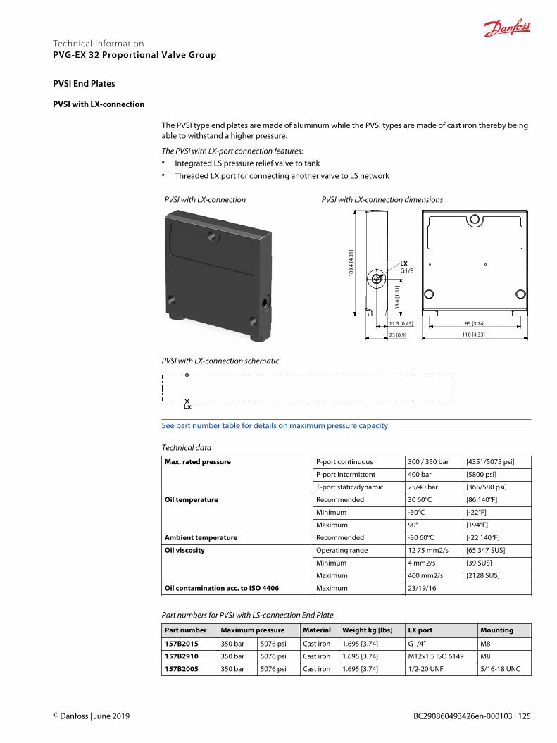
PVSI with LX-connection
The PVSI type end plates are made of aluminum while the PVSI types are made of cast iron thereby beingable to withstand a higher pressure.
The PVSI with LX-port connection features:• Integrated LS pressure relief valve to tank• Threaded LX port for connecting another valve to LS network
PVSI with LX-connection PVSI with LX-connection dimensions
109.
4 [4
.31]
38.4
[1.5
1]
110 [4.33]
95 [3.74]
23 [0.9]
11.5 [0.45]
LXG1/8
PVSI with LX-connection schematic
Lx
See part number table for details on maximum pressure capacity
Technical data
Max. rated pressure P-port continuous 300 / 350 bar [4351/5075 psi]
P-port intermittent 400 bar [5800 psi]
T-port static/dynamic 25/40 bar [365/580 psi]
Oil temperature Recommended 30 60°C [86 140°F]
Minimum -30°C [-22°F]
Maximum 90° [194°F]
Ambient temperature Recommended -30 60°C [-22 140°F]
Oil viscosity Operating range 12 75 mm2/s [65 347 SUS]
Minimum 4 mm2/s [39 SUS]
Maximum 460 mm2/s [2128 SUS]
Oil contamination acc. to ISO 4406 Maximum 23/19/16
Part numbers for PVSI with LS-connection End Plate
Part number Maximum pressure Material Weight kg [lbs] LX port Mounting
157B2015 350 bar 5076 psi Cast iron 1.695 [3.74] G1/4” M8
157B2910 350 bar 5076 psi Cast iron 1.695 [3.74] M12x1.5 ISO 6149 M8
157B2005 350 bar 5076 psi Cast iron 1.695 [3.74] 1/2-20 UNF 5/16-18 UNC
Technical InformationPVG-EX 32 Proportional Valve Group
PVSI End Plates
© Danfoss | June 2019 BC290860493426en-000103 | 125

The PVG-EX 32 PVSKM inline full flow cut-off module, also referred to as full flow cut-off modules, enablesan integrated full flow cut-off and High Pressure Carry Over (HPCO) functionality by means of theintegrated PVSKM spool, controlled either manually, hydraulically or electrohydraulically.
The PVG-EX 32 PVSKM modules, also referred to as full flow cut-off modules, inline full flow cut-off of flowor as an HPCO, High Pressure Carry Over port.
The PVSKM module allows a position anywhere in the PVG-EX 32 valve group, similar to a standard PVG-EX 32 basic module. The freedom of position of the PVSKM module in the PVG-EX 32 valve group enablesa full flow cut-off, of the entire valve group, by placing the PVSKM right after the PVP inlet module, oronly a part of the valve group, by placing the PVSKM elsewhere in the valve group.
The PVSKM module variants are based on a generic platform with a wide selection of additional features,enabling you to tailor the valve stack to comply with Category 2 or 3 safety systems according to ISO13849.
The PVSKM Full Flow Cut-Off Module features:• Threaded port for HPCO port
• Optional T0 facility and external T0 port
• Different PVSKM spool types depending on requested HPCO flow capacity
PVSKM Full Flow Cut Off module
PVSKM schematic
HPCO
1 0 2
Technical InformationPVG-EX 32 Proportional Valve Group
PVSKM Full Flow Cut Off Modules
126 | © Danfoss | June 2019 BC290860493426en-000103
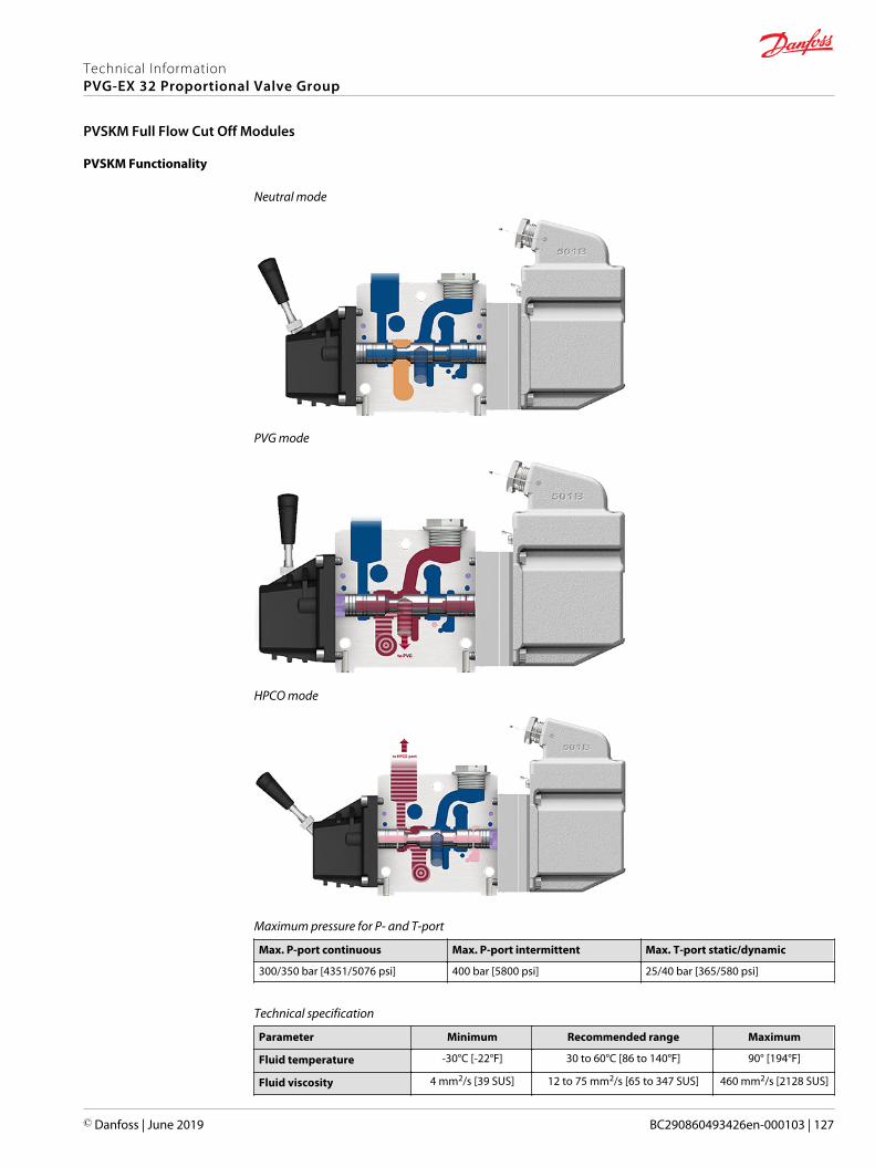
PVSKM Functionality
Neutral mode
PVG mode
HPCO mode
Maximum pressure for P- and T-port
Max. P-port continuous Max. P-port intermittent Max. T-port static/dynamic
300/350 bar [4351/5076 psi] 400 bar [5800 psi] 25/40 bar [365/580 psi]
Technical specification
Parameter Minimum Recommended range Maximum
Fluid temperature -30°C [-22°F] 30 to 60°C [86 to 140°F] 90° [194°F]
Fluid viscosity 4 mm2/s [39 SUS] 12 to 75 mm2/s [65 to 347 SUS] 460 mm2/s [2128 SUS]
Technical InformationPVG-EX 32 Proportional Valve Group
PVSKM Full Flow Cut Off Modules
© Danfoss | June 2019 BC290860493426en-000103 | 127

Technical specification (continued)
Parameter Minimum Recommended range Maximum
Fluid cleanliness 23/19/16 (according to ISO 4406)
Operating temperature Ambient: -30 to 60°C [-22 to 140°F]
Part number for PVSKM module
Part number P-port/HPCO-port T0 Facility Mounting
11099469 G3/4” yes
M811107369 1 1/16-12 UN yes
11117252 G3/4” -
Technical InformationPVG-EX 32 Proportional Valve Group
PVSKM Full Flow Cut Off Modules
128 | © Danfoss | June 2019 BC290860493426en-000103

PVSKM Spool
PVSKM Spool schematic
Theoretical Performance
Pressure drop P to P characteristic
10 20 30 40 50 60 70 80 90 100 110 120 130 (l/min)
(US gal/min)
140
2 4 6 8 10 12 14 16 18 20 22 24 26 28 30 32 34 38
10
9
8
7
6
5
4
3
2
1
0
PP
100
80
60
40
20
0
140
120
0
0
Q
Q
(bar)(psi)
Pressure drop from P to HPCO characteristics
2.5 5 7.5 10 12.5 15(bar)
(psi)
17.5 20
0.5 1 1.5 2 2.5 3 3.5 4 4.5 5
150
135
120
105
90
75
60
45
30
15
0
Q
1500
1200
900
600
300
0
2100
1800
0
(US gal/min) (l/min)
0
∆ P to HPCO
150 l/min spool
40 l/min spool
100 l/min spool
Technical InformationPVG-EX 32 Proportional Valve Group
PVSKM Full Flow Cut Off Modules
© Danfoss | June 2019 BC290860493426en-000103 | 129

Part number for PVSKM spool
Part number HPCO flow Actuation method
11100036 150 l/min [39.6 US gal/min]
PVE11116733 40 l/min [10.6 US gal/min]
11116734 100 l/min [26.4 US gal/min]
11111293 150 l/min [39.6 US gal/min] PVH/PVHC
Technical InformationPVG-EX 32 Proportional Valve Group
PVSKM Full Flow Cut Off Modules
130 | © Danfoss | June 2019 BC290860493426en-000103
PVAS Stay Bolts kit for various PVG combinations consist of three tie rods, six washers, six nuts and O-ring.Use the guide and reference tables how to choose PVAS kit.
The tie rods are inserted through the entire length of the PVG valve stack. The nuts are tightened at thepump side and at the end plate.
To find the PVAS kit that fits your PVG-EX 32 valve stack, you need to go to the table PVG-EX 32 modulestotal length on page 132 and find the length. Then go to the table PVAS Part Numbers on page 132 andfind the matching part number.
Technical InformationPVG-EX 32 Proportional Valve Group
PVAS Stay Bolts
© Danfoss | June 2019 BC290860493426en-000103 | 131

PVAS Part Numbers
PVAS part numbers according to accumulated length interval PVG-EX 32.
PVAS part numbers
Length, mm [in] Part number Length, mm [in] Part number
20 – 48 [0.79 – 1.89] 11188219 361 – 372 [14.21 – 14.65] 11188205
49 – 60 [1.93 – 2.36] 11188218 373 – 384 [14.69 – 15.12] 157B8026
61 – 72 [2.40 – 2.83] 157B8000 385 – 396 [15.16 – 15.59] 11188204
73 – 84 [2.87 – 3.31] 11188217 397 – 408 [15.63 – 16.06] 157B8007
85 – 96 [3.35 – 3.78] 157B8031 409 – 420 [16.10 – 16.54] 11188203
97 – 108 [3.82 – 4.25] 11188216 421 – 432 [16.58 – 17.01] 157B8027
109 – 120 [4.29 – 4.72] 157B8001 433 – 444 [17.05 – 17.48] 11188202
121 – 132 [4.76 – 5.20] 11188215 445 – 456 [17.52 – 17.95] 157B8008
133 – 144 [5.24 – 5.67] 157B8021 457 – 468 [17.99 – 18.43] 11188201
145 – 156 [5.71 – 6.14] 11188214 469 – 480 [18.47 – 18.90] 157B8028
157 – 168 [6.18 – 6.61] 157B8002 481 - 492 [18.94 – 19.37] 11188200
169 – 180 [6.65 – 7.09] 11188213 493 – 504 [19.41 – 19.84] 157B8009
181 – 192 [7.13 – 7.56] 157B8022 505 – 516 [19.88 – 20.31] 11188199
193 – 204 [7.60 – 8.03] 11188212 517 – 528 [20.35 – 20.79] 157B8029
205 – 216 [8.07 – 8.50] 157B8003 529 – 540 [20.83 – 21.26] 11188198
217 – 228 [8.54 – 8.98] 11188211 541 – 552 [21.30 – 21.73] 157B8010
229 – 240 [9.02 – 9.45] 157B8023 553 – 564 [21.77 - 22.20] 11188197
241 – 252 [9.49 – 9.92] 11188210 565 – 576 [22.24 – 22.68] 157B8030
253 – 264 [9.96 – 10.39] 157B8004 577 – 588 [22.72 – 23.15] 11188196
265 – 276 [10.43 – 10.87] 11188209 589 – 600 [23.19 – 23.62] 157B8061
277 – 288 [10.91 – 11.34] 157B8024 601 – 612 [23.66 – 24.09] 11188195
289 – 300 [11.38 – 11.81] 11188208 613 – 624 [24.13 – 24.57] 157B8081
301 – 312 [11.85 – 12.28] 157B8005 625 – 636 [24.61 – 25.04] 11188194
313 – 324 [12.32 – 12.76] 11188207 637 – 648 [25.08 – 25.51] 157B8062
325 – 336 [12.80 – 13.23] 157B8025 649 – 660 [25.55 – 25.98] 11188189
337 – 348 [13.27 – 13.70] 11188206 661 - 672 [26.02 – 26.46] 157B8082
349 – 360 [13.74 – 14.17] 157B8006
PVG-EX 32 modules total length
Table with total length of the PVG 32 depending on the number of PVB modules.
No. ofPVB 32
1 2 3 4 5 6 7 8 9 10 11 12
Lengthmm [in]
119[4.69]
167[6.57]
215[8.46]
263[10.35]
311[12.24]
359[14.13]
407[16.02]
455[17.91]
503[19.80]
551[21.69]
599[23.58]
647[25.47]
Technical InformationPVG-EX 32 Proportional Valve Group
PVAS Stay Bolts
132 | © Danfoss | June 2019 BC290860493426en-000103
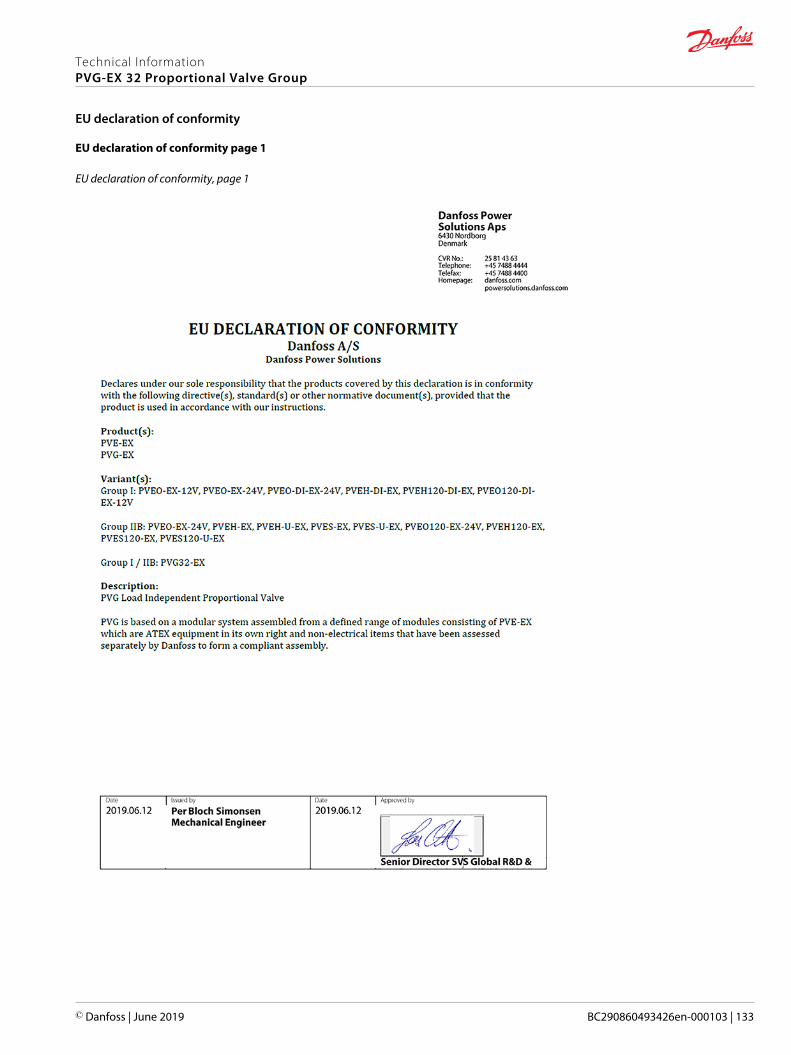
EU declaration of conformity page 1
EU declaration of conformity, page 1
Technical InformationPVG-EX 32 Proportional Valve Group
EU declaration of conformity
© Danfoss | June 2019 BC290860493426en-000103 | 133

EU declaration of conformity page 2
EU declaration of conformity, page 2
Technical InformationPVG-EX 32 Proportional Valve Group
EU declaration of conformity
134 | © Danfoss | June 2019 BC290860493426en-000103

EU declaration of conformity page 3
EU declaration of conformity, page 3
Technical InformationPVG-EX 32 Proportional Valve Group
EU declaration of conformity
© Danfoss | June 2019 BC290860493426en-000103 | 135

EU declaration of conformity page 4
EU declaration of conformity, page 4
Technical InformationPVG-EX 32 Proportional Valve Group
EU declaration of conformity
136 | © Danfoss | June 2019 BC290860493426en-000103

EU declaration of conformity page 5
EU declaration of conformity, page 5
Technical InformationPVG-EX 32 Proportional Valve Group
EU declaration of conformity
© Danfoss | June 2019 BC290860493426en-000103 | 137
Technical InformationPVG-EX 32 Proportional Valve Group
138 | © Danfoss | June 2019 BC290860493426en-000103

Technical InformationPVG-EX 32 Proportional Valve Group
© Danfoss | June 2019 BC290860493426en-000103 | 139

Technical InformationPVG-EX 32 Proportional Valve Group
140 | © Danfoss | June 2019 BC290860493426en-000103
Danfoss Power Solutions is a global manufacturer and supplier of high-quality hydraulic andelectric components. We specialize in providing state-of-the-art technology and solutionsthat excel in the harsh operating conditions of the mobile off-highway market as well as themarine sector. Building on our extensive applications expertise, we work closely with you toensure exceptional performance for a broad range of applications. We help you and othercustomers around the world speed up system development, reduce costs and bring vehiclesand vessels to market faster.
Danfoss Power Solutions – your strongest partner in mobile hydraulics and mobileelectrification.
Go to www.danfoss.com for further product information.
We offer you expert worldwide support for ensuring the best possible solutions foroutstanding performance. And with an extensive network of Global Service Partners, we alsoprovide you with comprehensive global service for all of our components.
Local address:
Danfoss Power Solutions GmbH & Co. OHGKrokamp 35D-24539 Neumünster, GermanyPhone: +49 4321 871 0
Danfoss Power Solutions ApSNordborgvej 81DK-6430 Nordborg, DenmarkPhone: +45 7488 2222
Danfoss Power Solutions (US) Company2800 East 13th StreetAmes, IA 50010, USAPhone: +1 515 239 6000
Danfoss Power Solutions Trading(Shanghai) Co., Ltd.Building #22, No. 1000 Jin Hai RdJin Qiao, Pudong New DistrictShanghai, China 201206Phone: +86 21 3418 5200
Danfoss can accept no responsibility for possible errors in catalogues, brochures and other printed material. Danfoss reserves the right to alter its products without notice. This also applies to productsalready on order provided that such alterations can be made without subsequent changes being necessary in specifications already agreed.All trademarks in this material are property of the respective companies. Danfoss and the Danfoss logotype are trademarks of Danfoss A/S. All rights reserved.
© Danfoss | June 2019 BC290860493426en-000103
Products we offer:
• DCV directional controlvalves
• Electric converters
• Electric machines
• Electric motors
• Hydrostatic motors
• Hydrostatic pumps
• Orbital motors
• PLUS+1® controllers
• PLUS+1® displays
• PLUS+1® joysticks andpedals
• PLUS+1® operatorinterfaces
• PLUS+1® sensors
• PLUS+1® software
• PLUS+1® software services,support and training
• Position controls andsensors
• PVG proportional valves
• Steering components andsystems
• Telematics
Hydro-Gearwww.hydro-gear.com
Daikin-Sauer-Danfosswww.daikin-sauer-danfoss.com