practical method for diffusion welding of steel plate in air method for diffusion welding of steel...
TRANSCRIPT
NASA TECHNICAL NOTE
04 0 u= ro
I
n z c
PRACTICAL METHOD FOR DIFFUSION WELDING OF STEEL PLATE I N AIR
by Thomas J. Moore and Kenneth H. Holko
Lewis Research Center Cleueland, Ohio 44135
... .. KiRTLAND AFB, N.1
r
NATIONAL AERONAUTICS A N D SPACE ADMINISTRATION WASHINGTON, D. C. JULY 1971
I’
https://ntrs.nasa.gov/search.jsp?R=19710021048 2018-07-15T14:57:29+00:00Z
TECH LIBRARY KAFB. NM
PRACTICAL METHOD FOR DIFFUSION WELDING 1I July 1971 OF STEEL PLATE I N AIR
7. Author(s) Thomas J. Moore and Kenneth H. Holko
9. Performing Organization Name and Address
Lewis Research Center National Aeronautics and Space Administration Cleveland, Ohio 44135
12. Sponsoring Agency Name and Address
National Aeronautics and Space Administration Washington, D. C. 20546
15. Supplementary Notes
- -I 16. Abstract
6. Performing Organization Code
I 8. Performing Organization Report No.
E-6236 10. Work Un i t No.
129-03 11. Contract or Grant No.i 13. Type of Report and Period Covered
Technical Note 14. Sponsoring Agency Code
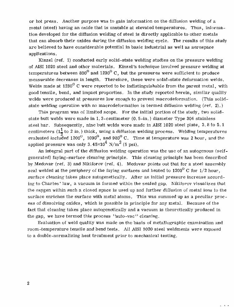
In this report , a simple and easily applied method of diffusion welding steel plate in a i r is described. Feasibility was clearly established for the diffusion welding of butt joints in AIS1 1020 steel without the use of a vacuum furnace o r hot press . The diffusion welds equaled the strength of the parent metal and passed a 180Obend test. These results a r e believed to have considerable potential in basic industry and aerospace applications since elaborate vacuum hot presses and related equipment a r e not required to make the diffusion welds.
I.
17. Key Words (Suggested by Author (s ) ) Metallic materials Unclassified - unlimited Machine element Diffusion welding
19. Security Classif. ( o f this report) 20. Security Classif. (o f th is page) 21. No. o f Pages 22. Price'
Unclassified Unclassified 25 $3.00
For sale b y t h e N a t i o n a l Technica l I n f o r m a t i o n Service, Spr ingf ie ld, V i rg in ia 22151
I

PRACTICAL METHOD FOR DIFFUSION WELDING OF STEEL PLATE IN AIR
by Thomas J. Moore and K e n n e t h H. Holko
Lewis Research Center
SUMMARY
This work was designed to determine whether a simple and easily applied diffusion welding operation could be developed for thick steel plate. The novel feature of this welding method is that diffusion welds a r e made in air with deadweight loading. Another objective of this work was to examine the use of an autogenous (self-generated) surface-cleaning principle (termed "auto-vac cleaning") to reduce the effects of surface oxides that normally hinder diffusion welding.
A ser ies of nine butt joints were diffusion welded in thick sections (3. 8 to 5 . 1 cm, 1-2 1to 2 in. ) of AISI 1020 s teel plate. Diffusion welds were attempted at three welding
temperatures (1200°, 1090°, and 980' C) using a deadweight pressure of 3.45X10⁴ N/m 2
(5 psi) and a 2-hour hold-time at temperature. Auto-vac cleaning operations prior to welding were also studied for the same three temperatures. Evaluation of weld quality was based on metallographic examination and room-temperature tensile and bend tests.
The results indicate that sound welds were produced at the higher two temperatures when the joints were previously fusion seal welded completely around the periphery. Also, auto-vac cleaning at 1200' C for 2-2
1 hours prior to diffusion welding was found to be highly beneficial, particularly when subsequent welding was accomplished at 1090' C.
This program is considered to be successful because sound diffusion welds were made in thick steel plate using simple procedures that can be readily applied in many industrial uses. Thus, the resul ts of this study a r e believed to have considerable potential in both aerospace and other industrial applications.
INTRODUCTION
In this report , a simple and easily applied method of diffusion welding s teel plate in air is described. The feasibility of applying this welding method was clearly established
f o r AISI 1020 steel . The main purpose of this study was to devise a practical method of diffusion welding steel plate; that is, a procedure that does not require a vacuum furnace
or hot press . Another purpose was to gain information on the diffusion welding of a metal (steel) having an oxide that is unstable at elevated temperatures. Thus, information developed for the diffusion welding of steel is directly applicable to other metals that can absorb their oxides during the diffusion welding cycle. The results of this study a r e believed to have considerable potential in basic industrial as well as aerospace applications.
Kinzel (ref. 1)conducted early solid-state welding studies on the pressure welding of AISI 1020 s teel and other materials. Kinzel's technique involved pressure welding at temperatures between 800' and 1230' C, but the pressures were sufficient to produce measurable decreases in length. Therefore, these were solid-state deformation welds. Welds made at 1230' C were reported to be indistinguishable from the parent metal , with good tensile, bend, and impact properties. In the study reported herein, s imilar quality welds were produced at pressures low enough to prevent macrodeformation. (This solid-s ta te welding operation with no macrodeformation is termed diffusion welding (ref. 2). )
This program was of limited scope. For the initial portion of the study, two solid-state butt welds were made in 1.3-centimeter (0.5-in. ) diameter Type 304 stainless steel bar . Subsequently, nine butt welds were made in AISI 1020 steel plate, 3 .8 to 5.1 centimeters (1-
2 1to 2 in. ) thick, using a diffusion welding process. Welding temperatures
evaluated included 1200°, 1090°, and 980' C. Time at temperature was 2 hour, and the applied pressure was only 3.45X10⁴ N/m 2 (5 psi).
An integral part of the diffusion welding operation was the use of an autogenous (selfgenerated) faying-surface cleaning principle. This cleaning principle has been described by Medovar (ref. 3) and Nikiforov (ref. 4). Medovar points out that for a steel assembly sea l welded at the periphery of the faying surfaces and heated to 1200' C for 1/2 hour, surface cleaning takes place autogenetically. After an initial pressure increase according to Charles ' law, a vacuum is formed within the sealed gap. Nikiforov visualizes that the oxygen within such a closed space is used up and further diffusion of metal ions to the surface enriches the surface with metal atoms. This was summed up as a peculiar process of dissolving oxides, which is possible in principle for any metal. Because of the fact that cleaning takes place autogenetically and a vacuum is theoretically produced in the gap, we have termed this process "auto-vac" cleaning.
Evaluation of weld quality was made on the basis of metallographic examination and room-temperature tensile and bend tests. All AISI 1020 steel weldments were exposed to a double-normalizing heat treatment prior to mechanical testing.
2
INITIAL STUDIES ON TYPE 304 STAINLESS STEEL BAR
In order to investigate the effectiveness of the auto-vac cleaning principle, two 1 .3 1centimeter-diameter by 3.8-centimeter (1/2-in. -diam by l--in. ) AIS1 Type 304 stainless2
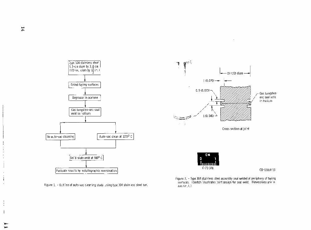
steel bars were prepared for butt welding to produce a 7.6-centimeter (3-in.) long weldment, As shown in the outline in figure 1, the faying surfaces were ground (40. 7X10⁻⁶ cm r m s (16 rms)) and degreased in acetone just prior to seal welding at the joint periphery. The seal is the first s tep in preparing the assembly for auto-vac cleaning. The assembly after gas tungsten-arc (GTA) seal welding in helium is shown in figure 2. The machined flange served to minimize restraint on the weld bead and to minimize the heat input required for seal welding.
Electron-beam sea l welding was also investigated but showed no advantage over GTA based on metallographic examination of solid-state welded joints. In addition, seal welds were made by the shielded-metal-arc (SMA) welding process. Longer heating t imes were required to produce the auto-vac cleaning effect for the SMA seal-welded assemblies. Thus, it was decided to use GTA seal welding.
Auto-vac cleaning was applied to one of the GTA-sealed assemblies by heating to 1200' C for 1 hour in argon. (An air-atmosphere furnace would have been equally sufficient.) The second sealed assembly was not auto-vac cleaned (see fig. 1). Both assemblies were subsequently solid-state welded in an induction-heated vacuum hot press a s follows :
Temperature, O C . . . . . . . . . . . . . . . . . . . . . . . . . . . . . . 980 Pressure , N/m 2 (ksi) . . . . . . . . . . . . . . . . . . . . . . . 1.88X10⁷ (2.73) Time at temperature, min . . . . . . . . . . . . . . . . . . . . . . . . . 5 Atmosphere, N/m 2 (torr) vacuum . . . . . . . . . . . . . . . . 2 . 7 ~ 1 0 - ~(2X10⁻⁵) Upset, mm (in.) decrease in length . . . . . . . . . . . . . . . . . . 0 .2 (0.008)
It should be noted here that since the joint periphery was sealed, the solid-state welds could have been made equally well in a i r . The vacuum hot press was used because it was readily available.
The beneficial effect of auto-vac cleaning prior to solid-state welding of Type 304 stainless steel is clearly shown in figure 3. With no auto-vac cleaning, a large amount of foreign material, believed to be principally chromium oxide, is concentrated near the weld line (fig. 3(a)). However, the weldment that was auto-vac cleaned shows little evidence of oxide at the weld line and extensive grain growth across the original interface (fig. 3(b)). These resul ts clearly demonstrate that auto-vac cleaning at 1200' C for 1hour removes foreign material from the faying surfaces of Type 304 stainless steel. Auto-vac cleaning thus makes it possible to subsequently produce high-quality welds in Type 304 stainless steel at 980' C. In these solid-state welding runs, however,
3
~ 1 1 1 1 1 . 1 1 1 1 1 I.,.,,,,,, I, I I, I , I. I.._. . 1.....1, , . -..
macrodeformation (0.2 mm (0.008 in. ) decrease in length) was produced. But it was felt that if the auto-vac cleaning principle could b e utilized in conjunction with a diffusion welding operation (no macrodeformation) , many more applications would b e found in industry. Thus, it was decided to attempt to diffusion weld AISI 1020 steel in air with deadweight loading.
EXPERIMENTAL PROCEDURES FOR STUDIES ON AIS1 1020 STEEL PLATE
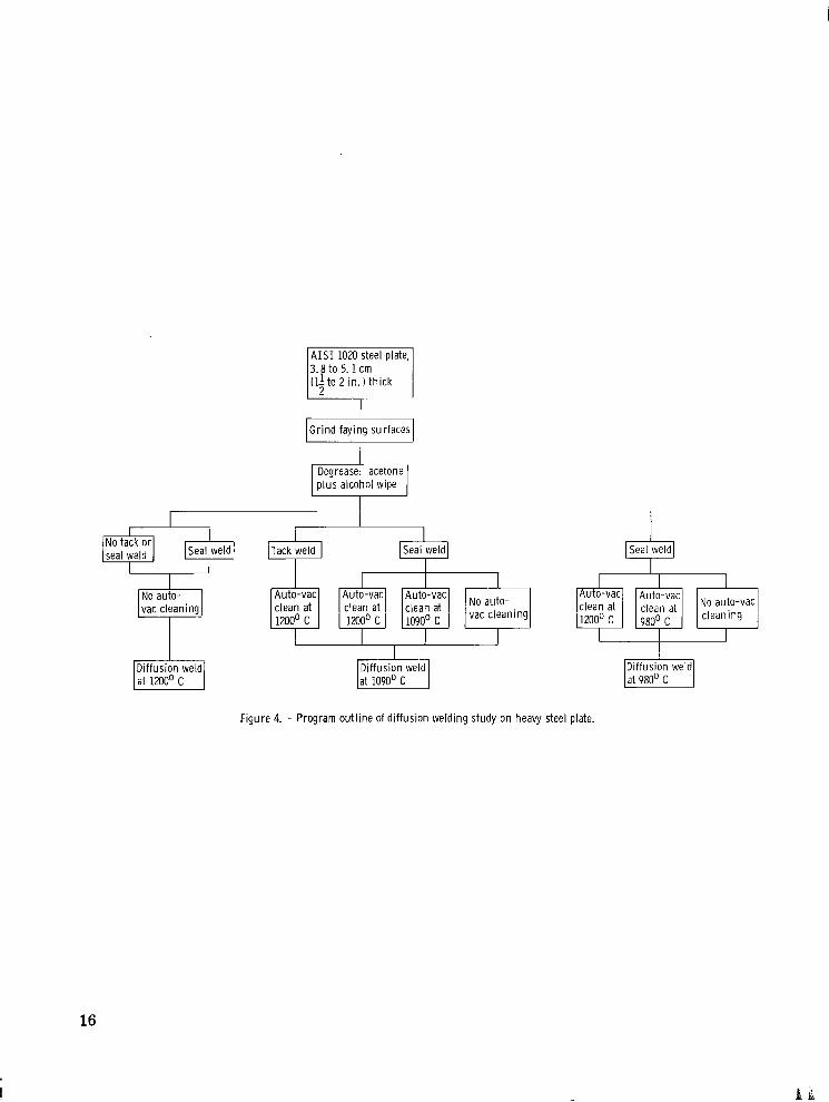
An outline of the welding program on AISI 1020 s teel plate is shown in figure 4. Nine butt joints were fabricated in 3.8- to 5.1-centimeter (1-1 to 2-in.) material using a2 diffusion welding process. Seal welds at the joint periphery were made prior to diffusion welding in most cases. And auto-vac cleaning effects were studied at three temperatures. Diffusion welds were subsequently produced at the same three temperatures as shown in figure 4 .
Weld Specimen Preparat ion
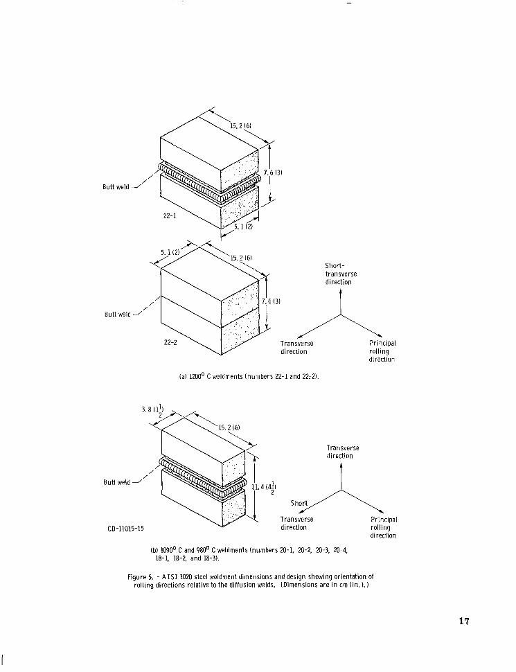
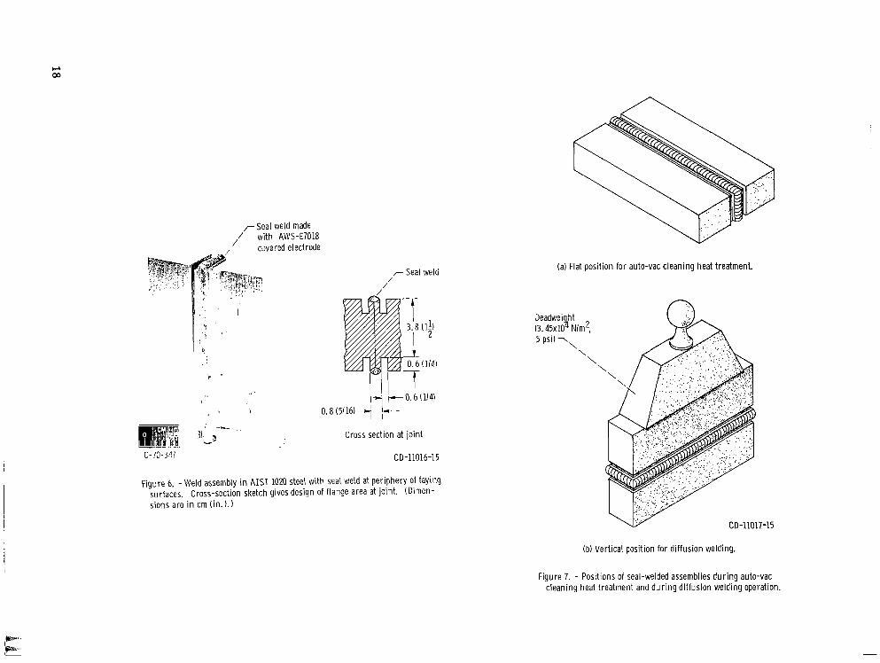
The dimensions of the weldments and the weld joint relation to the plate rolling direction a r e shown in figure 5 . In preparation for diffusion welding (see fig. 4 ) , the faying surfaces were ground to about a 4 0 . 7 ~ 1 0 - ~centimeter r m s (16 rms) finish. Just prior to assembly for diffusion welding, a protective oil was removed by wiping with acetone and then alcohol. In assembling the butt joint, C-clamps were used to position the faying surfaces. Tack welds were then applied. This was followed by seal welding along the flanges at the periphery of the faying surfaces, as shown in figure 6 . For both tack and sea l welding, the SMA welding process was used with 3.2-millimeter (1/8-in. ) diameter AWS-E7018 covered electrodes. The SMA welding process was used for sea l welding for convenience. No other seal-welding methods were considered.
A u t o -Vac S urface Clean i n g
The seal-welded assembly shown in figure 6 now was ready for auto-vac cleaning of the faying surfaces. Auto-vac cleaning was accomplished by placing the seal-welded assembly in an air-atmosphere, resistance-heated furnace. During the auto-vac cycle, the assembly was positioned flat as shown in figure 7. Three different auto-vac, t ime-temperature cycles were tr ied:
4
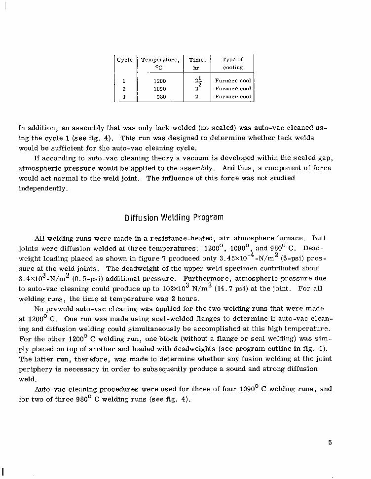
Cycle Tempera tu re , T ime , Typeof O C h r I cooling
1 1200 2-1 Furnace cool 2 I090 2 Furnace cool 3 980 2 Furnace cool
In addition, an assembly that was only tack welded (no sealed) was auto-vac cleaned using the cycle 1 (see fig. 4). This run was designed to determine whether tack welds would be sufficient for the auto-vac cleaning cycle.
If according to auto-vac cleaning theory a vacuum is developed within the sealed gap, atmospheric pressure would be applied to the assembly. And thus, a component of force would act normal to the weld joint. The influence of this force was not studied independently.
Diffusion Welding Program
All welding runs were made in a resistance-heated, air-atmosphere furnace. Butt joints were diffusion welded at three temperatures: 1200°, 1090°, and 980' C. Deadweight loading placed as shown in figure 7 produced only 3.45X10⁻⁴-N/m 2 (5-psi) p res s u r e at the weld joints. The deadweight of the upper weld specimen contributed about 3.4X10³-N/m 2 (0.5-psi) additional pressure. Furthermore, atmospheric pressure due to auto-vac cleaning could produce up to 102x103 N/m 2 (14.7 psi) at the joint. For all welding runs, the t ime at temperature was 2 hours.
No preweld auto-vac cleaning was applied for the two welding runs that were made at 1200' C . One run was made using seal-welded flanges to determine if auto-vac cleaning and diffusion welding could simultaneously b e accomplished at this high temperature. For the other 1200' C welding run, one block (without a flange o r seal welding) was s imply placed on top of another and loaded with deadweights (see program outline in fig. 4). The latter run, therefore, was made to determine whether any fusion welding at the joint periphery is necessary in order to subsequently produce a sound and strong diffusion weld.
Auto-vac cleaning procedures were used for three of four 1090' C welding runs, and for two of three 980' C welding runs (see fig. 4).
5

Eva I uation Procedure
Cross sections were taken at midlength from each weldment. Photomicrographs were obtained in the as -welded and double-normalized conditions.
Also, tensile and bend test specimens were machined from each of the weldments. But prior to machining the test specimens, all the weldments were double normalized as follows :
(1)Step 1: 900' C for 1hour, air cool (2) Step 2: 900' C for 1hour, air cool The weldments were double normalized for the purpose of minimizing structural dif
ferences in the AIS1 1020 steel materials that were exposed to various time-temperature auto-vac and diffusion welding cycles.
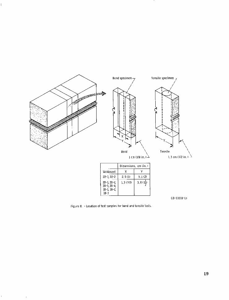
As shown in figure 8, bend specimens 1 cm by 2 .5 cm by 11.4 cm (3/8 in. by 1 in. by 4 1 in.) were prepared from two of the weldments. For the other weldments, bendzspecimens 1 cm by 1 . 3 cm by 11.4 cm (3/8 in. by 1/2 in. by 4-2
1in.) were used (fig. 8). Guided bends were made with a 19-mm (3/4-in. ) radius punch following the ASTM E190-64 specification. Transverse tensile specimens were obtained with the weld at the middle of the reduced section, also as shown in figure 8. The tensile specimens were 1.3-cm (1/2-in.) diameter at the threaded ends and 7.6-cm (3-in.) long. Diameter at the reduced section was 6.35 mm (1/4 in . ) with a 25.4-mm (1-in.) gage length. The tensile tes ts were conducted at a crosshead speed of 1 .3 mm (0.05 in. ) per minute.
RESULTS
In this section, resul ts a r e discussed in groups based on diffusion welding temperature: 1200°, 1090°, and 980' C . For all the diffusion weldments, weld quality was lower near the edges. These regions exhibited less grain growth across the weld line and more extensive oxides.
Diffusion Welds Made a t 1200' C
For these two diffusion welding runs, preweld auto-vac cleaning was not applied. Therefore, the objective was to obtain both auto-vac cleaning and subsequent diffusion welding during the time-temperature cycle.
Microstructure. - The microstructure of sealed weldment 22-1 near midthickness is shown in figure 9(a). Grain growth across the weld line is complete. Only a few isolated oxide particles a r e evident at the weld line.
6
Weldment 22-2, which was not seal welded prior to diffusion welding, exhibits a band of small oxide particles in the vicinity of the weld (fig. 9(b)). Absence of a seal weld thus has resulted in a lower quality weld than weldment 22-1. Longer t ime at 1200' C would tend to remove the oxide particles. This effect, however, was not investigated.
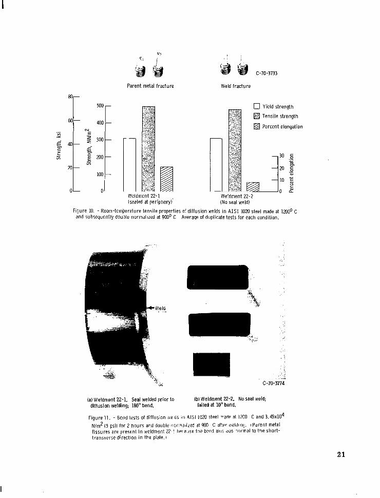
Tensile tests. - Duplicate room-temperature tensile tes t s (table I and fig. 10) clearly showed the beneficial effect of seal welding at the periphery of the faying su r faces. Fracture took place in the parent material for weldment 22-1 which w a s sea l welded. And the elongation was about 21 percent. Tensile specimens from weldmeiit 22-2 failed at the weld with only 8.5 percent elongation.
Bend tes ts . - The bend test resul ts (table I) exhibited a more dramatic difference than the tensile r e su l t s . As shown in figure 11 sealed weldment 22-1 passed a 180°bend, while unsealed weldment 22-2 broke at 10'. The parent metal f issures shown in weldment 22-1 in figure 11resulted from the fact that the long side of the bend specimen was parallel to the short-transverse direction of the plate (figs. 5 and 8).
Diffusion Welds Made at 10900 C
Four diffusion welding runs were made at 1090' C. For these runs (fig. 4 ) , effects of several auto-vac cleaning procedures were studied. And, in one case, there was no auto-vac cleaning applied prior to diffusion welding (weldment 20-4).
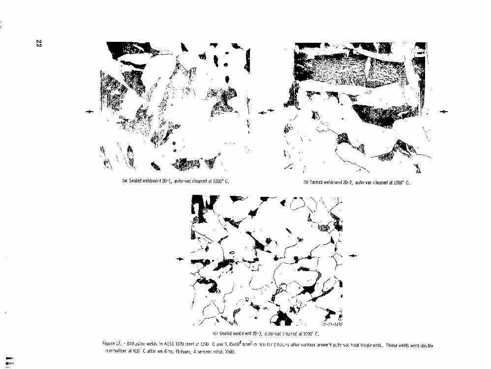
Microstructure. - Auto-vac cleaning at 1200' C proved to be extremely effective. Sealed weldment 20-1, which is shown in figure 12(a), exhibits complete grain growth across the weld line. In addition, there is practically no evidence of oxide particles at the weld line. Thus, the weld line is virtually not detectable. Weldment 20-2, which was tack welded rather than completely sealed welded, was of s imilar metallographic quality (fig. 12(b))under the tack welds. In regions between tack welds, however, diffusion welding was incomplete.
Sealed weldment 20-3 which was auto-vac cleaned at 1090' C showed grain growth across the weld line, but numerous oxides (fig. 12(c))were present. The 1090' C autovac cleaning is obviously much less effective than the 1200' C auto-vac cleaning.
Sealed weldment 20-4, which was not auto-vac cleaned prior to diffusion welding, was s imilar in microstructural appearance to weldment 20-3 (fig. 12(c)). But the oxides were larger and more continuous in weldment 20-4.
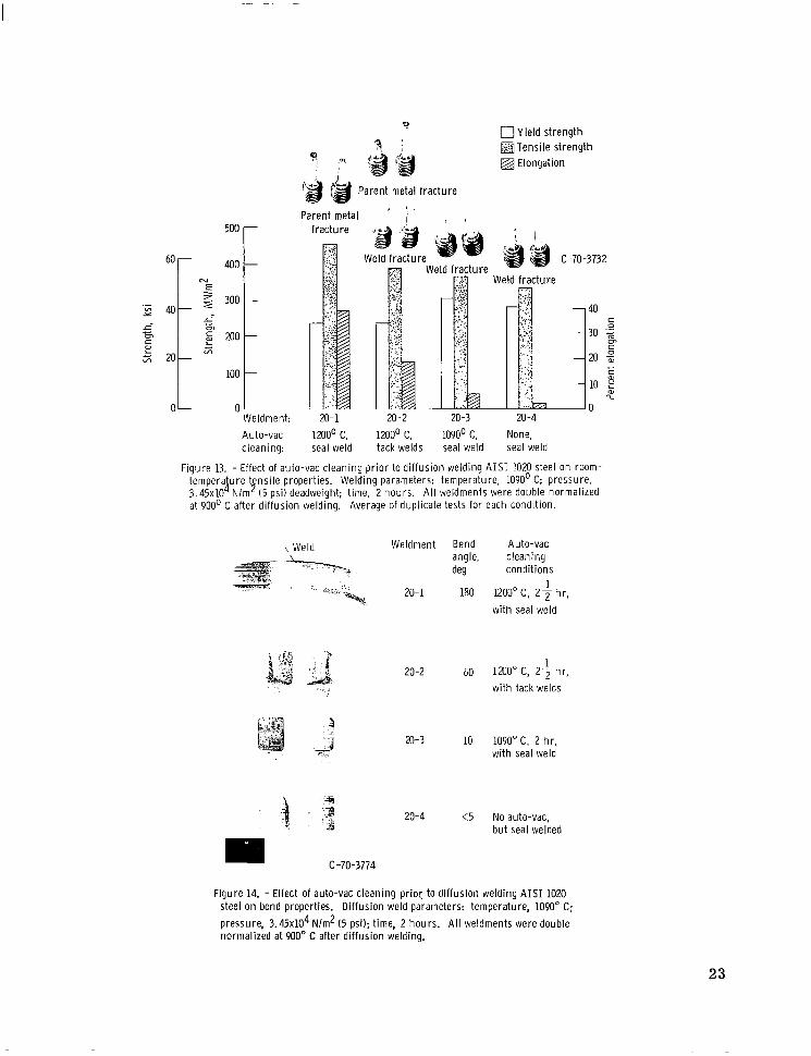
Tensile tes ts . - The resul ts of duplicate t ransverse tensile tests of these diffusion welds a r e shown in table I and figure 13. These data show that sealed weldment 20-1, which failed in the parent metal, had the best tensile strength and ductility. This advantage is probably the result of auto-vac cleaning at 1200' C. Weldment 20-2 gave variable resul ts (parent and weld fracture) showing that tack welding (rather than sea l welding) contributes to a variable weld quality.
7

Square-edge fracture at the weld was characterist ic of sealed weldment 20-3 which was auto-vac cleaned at 1090' C. Sealed weldment 20-4, which was not auto-vac cleaned prior to diffusion welding, had lower strength and ductility but a similar fracture to weldment 20-3. Weldments 20-1 and 20-2 had lower yield strengths than weldments 20-3 and 20-4 because the former two had larger grains (figs. 12(a) and (b)) than the latter two (fig. 12(c)) due to the 1200' C auto-vac cleaning cycle.
Bend tes ts . - The guided bend test specimens a r e shown in figure 14. Of the four diffusion weldments, only sealed weldment 20-1 gave a sound 180' bend. This result clearly shows that the 1200' C auto-vac cleaning followed by 1090' C diffusion welding produced a sound weld.
Weldment 20-2 was bent 60' before fracture occurred at the weld. Although this weldment was auto-vac cleaned at 1200' C , the assembly was tack welded rather than sea l welded. This bend result indicates that seal welding is necessary in order to achieve a 180' bend.
Auto-vac cleaning at 1090' C prior to diffusion welding was of no great benefit as measured by the bend test of sealed weldment 20-3. Fracture took place at the weld at 10' of bending, Weld fracture occurred at less than 5' of bending for sealed weldment 20-4, which was not auto-vac cleaned prior to diffusion welding. Thus, there appears to be only a small benefit from the 1090' C auto-vac cleaning (i.e. , 10' bends as compared to 5' bends). Hold t imes at 1090' C fo r longer than 2 hours for auto-vac cleaning would tend to produce cleaner surfaces. But this was not investigated. The side bend test is seen to be a more severe tes t of these diffusion welds than metallography or tensile tes ts .
Diffusion Welds Made at 980' C
As indicated in table I, two sealed assemblies (18-1 and 18-2) were diffusion welded at 980' C after auto-vac cleaning. And one diffusion weld was made (sealed assembly 18-3) which was not auto-vac cleaned prior to welding (fig. 4) .
Microstructure. - As has already been shown, 1200' C auto-vac cleaning effectively removes surface oxides. This is again evident in the s t ructure of sealed weldment 18-1, shown in figure 15(a), where oxides a r e essentially absent. Grain growth across the weld line has virtually eliminated all evidence of the weld. In other areas of this same weldment (not shown) a few small oxide particles were present at the weld line.
For the weldment cleaned at lower temperatures (fig. 15(b)), a line of oxides at the weld with very limited grain growth across the weld line is typical. Auto-vac cleaning at 980' C is clearly not effective. Sealed weldment 18-3, which was not preweld autovac cleaned, was s imilar in appearance to 18-2.
8
--
Tensile tes ts . - In duplicate tensile tes t s of weldment 18-1, failure took place in the parent metal (see table I). Thus, on this basis , the weld appears to b e as strong as the parent metal. Tensile testing of weldments 18-2 and 18-3 was not done because the blanks fell apart at the weld joint i n machining.
Bend tests. - A poor result was obtained in the bend specimen from weldment 18-1. As shown in table I, this specimen failed at the weld at a 45' bend angle. This bend fail
u r e was surprising because the weld had appeared to be sound in metallographic examination and it exhibited good t ransverse tensile strength. The poor bend tes t result indicates that the 980' C weld temperature is not sufficiently high to eliminate a line of weakness at the weld line. Thus, although the preweld auto-vac cleaning at 1200' C removed the oxides, a diffusion welding temperature greater than 980' C appears to b e necessary
4during the 2-hour hold t ime at 3 . 4 5 ~ 1 0 N/m 2 ( 5 psi). Higher pressure or longer hold t ime might also produce a stronger weld.
Bend tests were not made for weldments 18-2 and 18-3 because the blanks broke at the weld line during machining.
DISCUS S ION
Seal welding at the joint periphery was shown to be necessary in order to produce a sound, strong diffusion weld in a i r . For sealed assemblies diffusion welded at 1200' C , preweld auto-vac cleaning was not necessary because both cleaning and diffusion welding take place during the 2-hour weld t ime at this temperature. Diffusion welding was made possible by the fact that the oxides were dissolved in the parent metal and trapped gases were absorbed by the parent metal (the auto-vac cleaning effect). Ludemann (ref. 5) has pointed out that some FeO also may be reduced by carbon during diffwion welding. In the 1090' C diffusion welding studies, it was demonstrated that a high-quality weldment s imilar to 22-1 could b e produced providing a 1200' C auto-vac cleaning cycle was applied prior to diffusion welding.
We have seen that a seal-welded assembly not auto-vac cleaned in advance (weldment 22-1) could be diffusion welded successfully at 1200' C. However, sealed weldment 20-4, which was diffusion welded at 1090' C without preweld auto-vac cleaning, failed the bend test at less than 5'. Thus, it is evident that temperature plays a major role in auto-vac cleaning and diffusion welding.
9
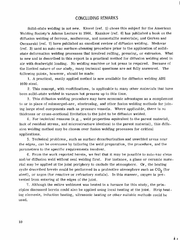
CONCLUDING REMARKS
Solid-state welding is not new. Kinzel (ref. 1) chose this scbject for the American Welding Society's Adams Lecture in 1944. Kazakov (ref. 6) has published a book on the diffusion welding of ferrous , nonferrous , and nonmetallic materials; and Gerken and Owczarski (ref. 7) have published an excellent review of diffusion welding. Medovar (ref. 3) used an auto-vac surface-cleaning procedure prior to the application of solid-s ta te deformation welding processes that involved rolling, pressing, or extrusion. What is new and is described in this report is a practical method for diffusion welding s teel in air with deadweight loading. No welding machine or hot press is required. Because of the limited nature of our study, many technical questions a r e not fully answered. The following points, however , should be made:
1. A practical, easily applied method is now available for diffusion welding AIS1 1020 steel.
2. This concept, with modifications, is applicable to many other materials that have been solid-state welded in vacuum hot presses up to this time.
3 . This diffusion welding procedure may have economic advantages as a complement to or in place of submerged-arc, electroslag, and other fusion welding methods for joining large steel components such as pressure vessels. Where applicable, there is no thickness o r cross-sectional limitation to the joint to b e diffusion welded.
4. For technical reasons (e. g. , weld properties equivalent to the parent material , lack of residual s t r e s s , and microstructure identical to the parent material) , this diffusion welding method may be chosen over fusion welding processes for critical applications.
5. Technical problems, such as surface decarburization and unwelded a reas near the edges, can be overcome by tailoring the weld preparation, the procedure, and the parameters to the specific requirements involved.
6. From the work reported herein, we feel that it may be possible to auto-vac clean and/or diffusion weld without sea l welding first. For instance, a glass o r ceramic material may be applied at the joint periphery to exclude the atmosphere. Or, the heating cycle described herein could be performed in a protective atmosphere such as C 0 2 (for steel) , o r argon (for reactive o r refractory metals). In this manner, oxygen is prevented from entering at the edges of the joint.
7. Although the entire weldment was heated in a furnace for this study, the principles discussed herein could also be applied using local heating at the joint. Strip heating elements, induction heating, ultrasonic heating o r other suitable methods could be used.
10
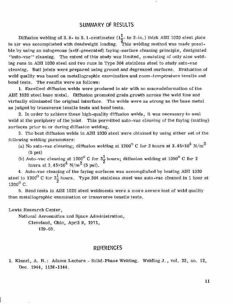
SUMMARY OF RESULTS
Diffusion welding of 3 .8- to 5. l-centimeter (11- to 2-in.) thick AISI 1020 steel plate2
in air was accomplished with deadweight loading. This welding method was made possible by using an autogenous (self -generated) faying-surface cleaning principle, designated "auto-vac" cleaning. The extent of this study was limited, consisting of only nine welding runs in AISI 1020 s teel and two runs in Type 304 stainless steel to study auto-vac cleaning. Butt joints were prepared using ground and degreased surfaces. Evaluation of weld quality was based on metallographic examination and room-temperature tensile and bend tes ts . The results were as follows:
1. Excellent diffusion welds were produced in air with no macrodeformation of the AISI 1020 steel base metal. Diffusion promoted grain growth across the weld line and virtually eliminated the original interface. The welds were as strong as the base metal as judged by t ransverse tensile tes t s and bend tests.
2. In order to achieve these high-quality diffusion welds, it was necessary to sea l weld at the periphery of the joint. This permitted auto-vac cleaning of the faying (mating) surfaces prior to or during diffusion welding.
3. The best diffusion welds in AISI 1020 steel were obtained by using either set of the following welding parameters:
(a) No auto-vac cleaning; diffusion welding at 1200' C for 2 hours at 3.45X10⁴ N/m 2
(5 Psi) (b) Auto-vac cleaning at 1200' C for 2-2
1 hours; diffusion welding at 1090' C for 2 hours at 3 . 4 5 ~ 1 0 ~N/m2 (5 psi).
4. Auto-vac cleaning of the faying surfaces was accomplished by heating AISI 1020 s teel to 1200' C for 31 hours. Type 304 stainless steel was auto-vac cleaned in 1hour at
21200O c .
5. Bend tes t s in AISI 1020 s teel weldments were a more severe test of weld quality than metallographic examination or t ransverse tensile tes ts .
Lewis Research Center, National Aeronautics and Space Administration,
Cleveland, Ohio, April 9 , 1971, 129-03.
REFERENCES
1. Kinzel, A. B. : Adams Lecture - Solid-Phase Welding. Welding J . , vol. 23, no. 12 , Dec. 1944, 1124-1144.
11
2. Anon. : Terms and Definitions. AWS A3.0-69, American Welding Society, 1969.
3. Medovar, B. I. ; et al. : New Methods of Producing Intermediate Pieces for Welding Dissimilar Steels. Automatic Welding, vol. 20, no. 10, 1967, pp. 55-59.
4. Nikiforov, G. D. ; et al. : The Mechanism of Joint Formation in Welding and Brazing. Welding Prod. , vol. 14, no. 12, 1967, pp. 6-12.
5. Ludemann, W. D. : A Fundamental Study of the Pressure Welding of Dissimilar Metals Through Oxide Layers. Ph. D. Thesis, Rep. UCRL-50744 , Univ. California, Oct. 1969.
6. Kazakov, N. F. : Diffusion Welding in a Vacuum. Rep. FTD-MT-24-419-68, Foreign Technology Div., Air Force Systems Command, Aug. 13, 1969. (Available from DDC as AD-698097. )
7. Gerken, J. M. ; and Owczarski, W. A. : A Review of Diffusion Welding. Bull. No. 109, Welding Research Council, Oct. 1965.
12
--
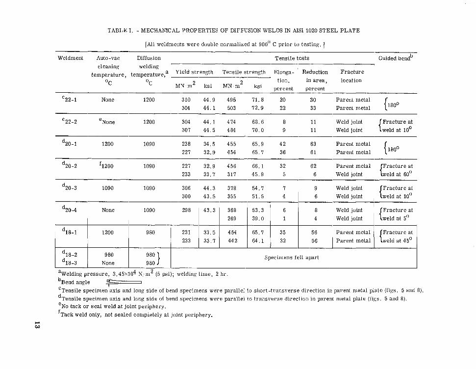
TABLE I. - MECHANICAL PROPERTIES OF DIFFUSION WELDS IN AIS1 1020 STEEL PLATE
[All weldments were double normalized at 900' C pr ior to testing. 3
Weldment Auto-vac Diffusion Tensile tests Guided bend' cleaning welding
OC O C MN m2 2ksi MN in tion, in area,
ksi percent percent location
C 22-1 None 1200 310 304
44.9 495 4 4 . 1 503
71.8 20 30 72.9 22 33
Parent metal Parent ineta1 {180'
c22-2 eNone 1200 304 4 4 . 1 474 68.6 8 11 Weld joint Frac ture at 307 44 .5 484 70.0 9 11 Weld joint weld at 10'
d20-1 1200 1090 238 227
34.5 455 32.9 454
65.9 42 63 65.7 36 61
Parent metal Parent metal {180'
d20-2 3 2 0 0 1090 227 32.9 456 66 .1 32 62 Parent metal Frac ture at 233 33.7 317 45.9 5 6 Weld joint {weld at 60'
d20-3 1090 1090 306 44 .3 378 54.7 7 9 Weld joint Frac ture at 300 43 .5 , 355 51.5 4 1 6 Weld joint weld at 10'
d20-4 None 1090 298 43 .3 368 53.3 6 8 Weld joint Frac ture a t 269 39.0 1 4 Weld joint weld at 5'
d18-1 1200 9 80 231 33.5 454 65.7 35 56 233 33.7 442 64 .1 32 56
d18-2 980 Specimens fell apart d18-3 None 980
temperature, temperature,a Yield strength Tensile strength Elonga- ' Reduction Frac ture
aWelding pressure , 3 . 4 5 ~ 1 0 ~N;m2 (5 psi); welding t ime, 2 hr 'Bend angle 'Tensile specimen axis and long side of bend specimens were parallel l o short-transverse direction in parent metal plate (figs. 5 and 8). dTensile specimen axis and long side of bend Specimens were parallel to t ransverse direction in parent metal plate (figs. 5 and 8). eNo tack o r seal weld at joint periphery. fTack weld only, not sealed completely at joint periphery.
CL W
1.3-cm diam by 3.8 cm ( l /Z - in . diam by 1’ in. 1 L-13 (1/2) diam J,
I 1 (0.040) + If Gas tungsten
/ a r c seal weld i n he l ium
weld in h e l i u m
if Cross section at jo in t
I Auto-vac clean at 1200° C I
Solid-state weld at 980’ Ct C-71-346 CD-11014-15Evaluate resul ts by metallographic examination
! Figure 2. - Type 304 stainless steel assembly seal welded at periphery of faying surfaces. (Sketch i l lustrates jo in t design for seal weld. Dimensions are in
Figure 1. - Out l ine of auto-vac cleaning study u s i n g type 304 stainless steel bar. mm (in. 1. )
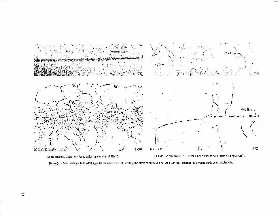
(a) No auto-vac cleaning pr ior to solid-state welding at 980" C. (b) Auto-vac cleaned at 1200" C for 1 hour pr ior to solid-state welding at 980" C.
Figure 3. - Solid-state welds i n A I S 1 Type 304 stainless steel i l lustrat ing the effect of preweld auto-vac cleaning. Etchant, 10 percent oxalic acid, electrolytic.
~ A I S I1020 steel plate, I 3.8 to 5. 1cm (2to 2 in.) th i ck
I i
Seal weld Seal weldI *~
I I I I
Dif fusion weld Di f fusion weld at I M O O c Llogo.c1
Figure 4. - Program ou t l i ne of di f fusion welding study o n heavy steel plate.
16
//
Butt weld J
Butt weld -//
Shor t -t ransverse direct ion
I 7jb(3)
Transverse d i rec t i on
Pr incipal ro l l i ng direct ion
Transverse direct ion
(a) 1200' C weldments (numbers 22-1 and 2 2 ~ 2 ) .
3.
Butt weld -/
4
Transverse d i rec t i on
Pr incipal ro l l i ng direct ion
CD-11015-15
(b) 1WO0C and 980' C weldments (numbers 20-1, 20-2, 20-3, 20-4, 18-1, 18-2, and 18-3).
Figure 5. - A I S 1 1020 steel weldment dimensions and design showing or ientat ion of r o l l i n g direct ions relative to t h e d i f f us ion welds. (Dimensions are in cm (in. ).)
17
,-Seal weld made 1 with AWS-E7018’ covered electrode
,-Seal weld /
/
( 1112
( 1 / 4 . c
, \ ~ ~ 0 . 6 ( 1 \ 4 ) 0.8(5116)+ ,
Cross section at jo int
C-70-347 CD-11016-15
Figure 6. - Weld assembly in A I S 1 1020 steel w i th seal weld at per iphery of faying surfaces. Cross-section sketch gives design of flange area at joint. (Dimensions are in cm (in. ) . )
it
I---
(a) Flat position for auto-vac cleaning heat treatment.
Deadwei$ht (3 .45~10 Nlm’, 5 psi) 7
\ \ \
(b) Vertical position for d i f fusion welding.
Figure 7, - Positions of seal-welded assemblies d u r i n g auto-vac cleaning heat treatment and d u r i n g di f fusion welding operation.
8-
Bend specimen, Tensila specimen
Bend \ \
1 cm (3/8 in. ) 1
IDimensions, cm (in. 1 I I Weldment
22-1.22-2
20-1,20-2, 20-3,20-4, 18-1, 18-2,1 18-3 ~
Figure 8. - Location of test samples for bend and tensi le tests.
/
\ Tensile \
1.3 cm (1/2 in.)
CD-11018-15
19

N 0
*+
la) Sealed weldment 22-1. (b) Unsealed weldment 22-2.
Figure 9. - Di f fus ion welds i n A I S 1 1020 steel made at 1200 C w i th n o preweld auto-vac treatment. Af ter welding the weldments were double normalized at 900" C. Etchant, 4 percent ni ta l ; X5M).
4
u
Parent metal f rac tu re
*r 500
60
.v)
e E 5;
M
Weldment 22-1 ,
(sealed at per iphery)
@ C-70-3733
Weld f rac tu re
0Yield strength
Tensi le strength
Percent elongation
10 2 L
o z Weldment 22-2 (No seal weld)
Figure 10. - Room-temperature tens i l e properties of d i f f us ion welds in A I S 1 1020 steel made at 1200° C and subsequently double normal ized at 900' C Average of duplicate tests fo r each condition.
*Weld.-
I1 C-70-3774
(a) Weldment 22-1. Seal welded p r io r t o (b) Weldment 22-2. No seal weld; d i f fusion welding; 180" bend. failed at 10" bend.
F igu re 11. - Bend tests of d i f fusion welds in A I S 1 1020 Steel made at 1200 C and 3 . 4 5 ~ 1 0 ~ N/m2 ( 5 psi1 for 2 h o u r s and double normal ized at 900 C after weldincj. { P a r e n t metal f i ssu res are present in weldment 22-1 lipcause t he bend axis *as i o r m a l to t h e sho r t -t ransverse direct ion i n the plate. I
21
t 4* 4
'E F
(a) Sealed weldment 20-1, auto-vac cleaned at 1200" C. (b) Tacked weldment 20-2, auto-vac cleaned at 1200' C.
4
(c) Sealed weldment 20-3, auto-vac cleaned at 1090' C.
Figure 12. - Diffusion welds i n A I S 1 1020 steel at 1090 C and 3 . 4 5 ~ 1 0 ~N/m2 15 psi) for 2 hou rs after various preweld auto-vac heat treatments. These welds were double normalized at 900' C after welding. Etchant, 4 percent nital: X500.
P 0Yield strengthR @Tens i l e strength
Elongation pa Parent metal f rac tu re
Parent metal ' i I , -500
6or400
100
0 i o..'eldment: 20-1 20-2 20-3 20-4
Auto-vac 1200° C, 1200° C, 1090' C, None, cleaning: seal weld tack welds seal weld seal weld
Figure 13. - Effect of auto-vac cleaning p r i o r to d i f f us ion welding AISI 1020 steel o n room-tempera u r e t ns i l e properties. Welding parameters: temperature, 1090' C; pressure,3 . 4 5 ~ 1 0d N l m5 ' .(5 psi) deadweight; t ime, 2 hours. A l l weldments were double normal ized at 900' C af ler d i f fusion welding. Average of duplicate tests for each condition.
YWe ld Weldment Bend angle,
--\ de9
_ - 20-1 180
20-2 50
20-3 10
20-4 <5
C-70-3774
Auto-vac cleaning condi t ions
11200°C, 2 7 hr, wjith seal weld
1 1ZO" C, 2 1 hr , w i th tack welds
1O9O0C, 2 hr. w i th seal weld
No auto-vac, b u t seal welded
Figure 14. - Effect of auto-vac cleaning p r i o r to d i f f us ion welding AISI 1020 steel o n bend properties. Di f fusion weld parameters: temperature, 1090' C; pressure, 3 . 4 5 ~ 1 0 ~N/m2 (5 psi); time, 2 hours. A l l weldments were double normal ized at 900' C after d i f f us ion welding.
23

c
t t
6FY (0
c
I
(a) Sealed weldment 18-1, auto-vac cleaned at 1200" C. (b) Sealed weldment 18-2, auto-vac cleaned at 980" C.
Figure 15. - Dif fusion welds in A I S 1 1020 steel made at 980" C and 3 . 4 5 ~ 1 0 ~N/m2 (5 psi) for 2 hours, after preweld auto-vac heat treatments. Al l weldments were double normalized at 400" C after welding. Etchant, 4 percent nital; XNO.
e -2
M I Q)h3 w Q,
NATIONAL AND SPACE ADMINISTRA?AERONAUTICS ION
WASHINGTON,D. C. 20546
OFFICIAL BUSINESS FIRST CLASS MAIL PENALTY FOR PRIVATE USE $300
POSTAGE A N D FEES PAID NATIONAL AERONAUTICS A N
SPACE ADMINISTRATION
004 001 CL U 17 710716 S O O 9 0 3 D S DEPT OF T H E A I R FORCE WEAPONS L A B O R A T O R Y /WLOL/ ATTN: f LOU R O W M A N # C H I E F T E C H L I B R A R Y K l R T t A N D A F R NM R7Ll.7
If Undeliverable (Section 158POSTMASTER: Postal Manual) Do Nor Return
“The aeronautical and-’space activities of the United Stntes shall be conducted so as to conjebute . . . to the expansion of human knowledge of pheizoniena in ithe .at?itosphere and space. T h e Administration shall provide for the ipidest prncticable and appropriate dissemination of information concerning its activities and the results thereof.”
-NATIONALAERONAUTICSA N D SPACE ACT OF 1958 3
NASA SCIENTIFIC AND TECHNICAL PUBLICATIONS
TECHNICAL REPORTS: Scientific and technical information coniidered importanf, complete, and a lasting contribution to existing knowledge.
TECHNICAL NOTES: Information less broad in scope but nevertheless of importance as a contribution to existing knowledge.
TECHNICAL MEMORANDUMS: Information receiving limited distribution because of preliminary data, security classification, or other reasons.
CONTRACTOR REPORTS: Scientific and technical information generated under a NASA contract or grant and considered an important contribution to existing knowledge.
TECHNICAL TRANSLATIONS: Information published in a foreign language considered to merit NASA distribution in English.
SPECIAL PUBLICATIONS: Information derived from or of value to NASA activities. Publications include conference proceedings, monographs, data compilations, handbooks, sourcebooks, and special bibliographies.
TECHNOLOGY UTILIZATION PUBLICATIONS: Information on technology used by NASA that may be of particular interest in commercial and other non-aerospace applications. Publications include Tech Briefs, TEchnology utilization Reports and Technology Surveys.
Details on the availability of these publications may be obtained from:
SCIENTIFIC AND TECHNICAL INFORMATION OFFICE
NATlONA L AE R 0NAUT1C S AN D SPACE AD MINISTRATI0N Washington, D.C. PO546