powercore pcd air cleaners - donaldson company pcd air cleaners poercore ® air cleaners engine...
TRANSCRIPT
PowerCore® PCD Air Cleaners POWERCORE
® AIR CLEANERS
donaldson.com Engine Air Filtration • 45
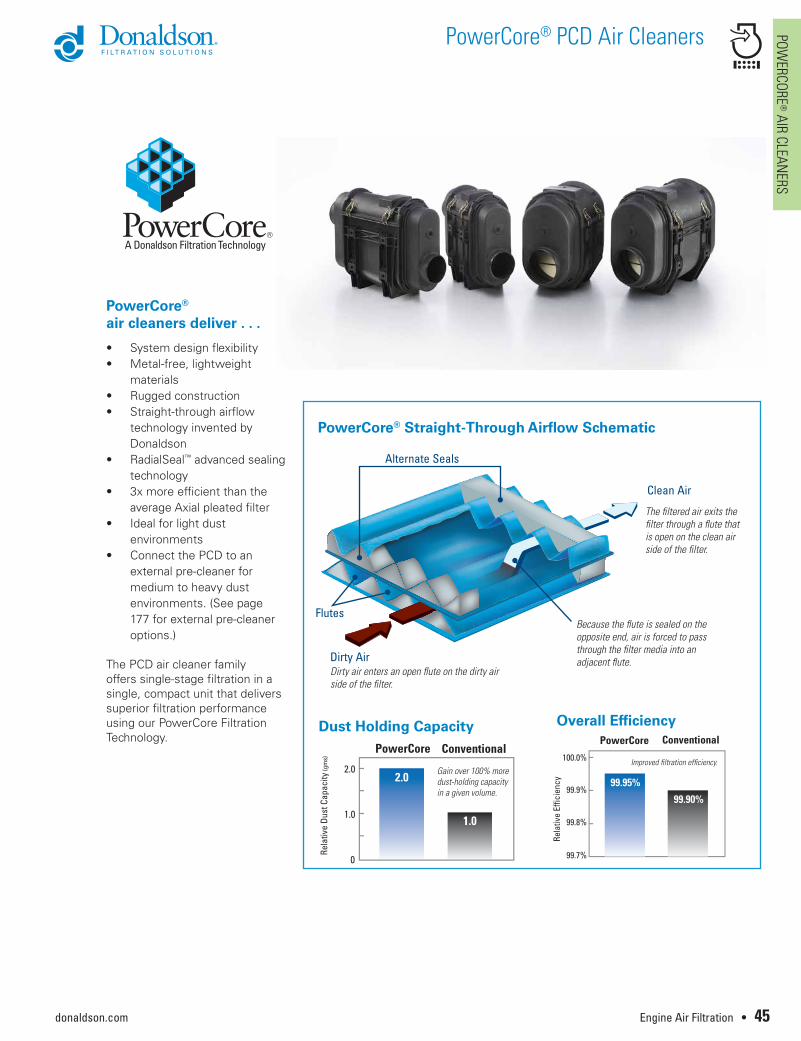
Gain over 100% more dust-holding capacity in a given volume.
Dust Holding Capacity Overall Efficiency
PowerCore® Straight-Through Airflow Schematic
Improved filtration efficiency.
99.90%
Clean Air
Dirty Air
Alternate Seals
Flutes
Dirty air enters an open flute on the dirty air side of the filter.
The filtered air exits the filter through a flute that is open on the clean air side of the filter.
Because the flute is sealed on the opposite end, air is forced to pass through the filter media into an adjacent flute.
PowerCore® air cleaners deliver . . .
• System design flexibility• Metal-free, lightweight
materials• Rugged construction• Straight-through airflow
technology invented by Donaldson
• RadialSeal™ advanced sealing technology
• 3x more efficient than the average Axial pleated filter
• Ideal for light dust environments
• Connect the PCD to an external pre-cleaner for medium to heavy dust environments. (See page 177 for external pre-cleaner options.)
The PCD air cleaner family offers single-stage filtration in a single, compact unit that delivers superior filtration performance using our PowerCore Filtration Technology.
1.0
2.0
0
PowerCore Conventional
Rela
tive
Dust
Cap
acity
(gm
s)
2.0
1.0
99.95%
99.90%
100.0%
99.9%
99.8%
99.7%
PowerCore Conventional
PowerCore® PCD Air Cleaners PO
WER
CORE
® A
IR C
LEAN
ERS
donaldson.com46 • Engine Air Filtration
PCD PowerCore Air Cleaner is Ideal for Light Dust Environments
This air cleaner family offers single-stage filtration in a compact unit that delivers superior filtration performance using our PowerCore® Filtration Technology.
This non-metal air cleaner (except for cover clamps) is ideal for equipment operating in light dust environments.
Applications• Light dust conditions with engine
airflow ranges up to 974 cfm. • Obround housing shape allows
for a narrow or wide mounting orientation.
• Models have side filter service access
• Sustained temperature tolerance: -40 ºF to 180 °F / -40 ºC to 82 °C
Features• More compact at a given
performance level than standard pleated filters
• Non-metal filters • Improved engine protection:
no media movement, expansion, contraction or bunching
• Improved contaminant encapsulation: dust and dirt stay contained in filter during service
• Improved handling and maintenance: lighter and smaller
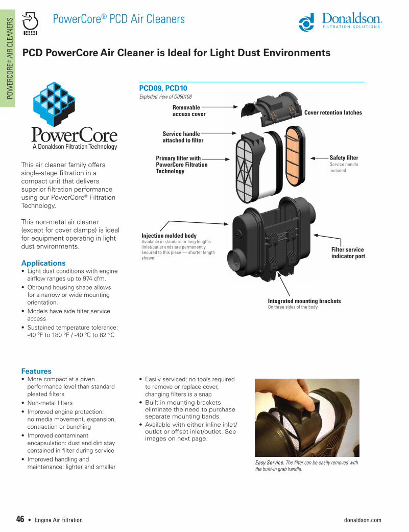
Primary filter with PowerCore Filtration Technology
Safety filter Service handleincluded
Injection molded body Available in standard or long lengths (inlet/outlet ends are permanently secured to this piece — shorter length shown)
Filter service indicator port
Integrated mounting bracketsOn three sides of the body
Removable access cover
Service handle attached to filter
PCD09, PCD10Exploded view of D090108
• Easily serviced; no tools required to remove or replace cover, changing filters is a snap
• Built in mounting brackets eliminate the need to purchase separate mounting bands
• Available with either inline inlet/outlet or offset inlet/outlet. See images on next page.
Easy Service. The filter can be easily removed with the built-in grab handle.
Cover retention latches
PowerCore® PCD Air Cleaners POWERCORE
® AIR CLEANERS
donaldson.com Engine Air Filtration • 47
Excellent Performance in Half the Space
Mounting FlexibilityWith mounting locations on three sides of the housing, the PCD series offers a great deal of flexibility for a wide variety of installations.
U-clips are shipped with each air cleaner. Affix these to the mounting location (all in the same direction) and slide the housing into place. See dimensional illustration for u-clip mounting hole pattern on page 50.
The PCD air cleaner needs to be mounted to equipment on at least one mounting location (base, or either of two sides). It can also be mounted at two points, using the base and one side. It should not be mounted using the two side mounting locations — as this will cause pressure/flexing, and could result in leaks. (See illustration, on right. Xs represent u-clips mounted on both sides adjacent to the access cover.) The u-clips accept M8 threaded fasteners. Maximum torque is 18 N•m.
D090108 Offset Inlet/Outlet
INLET
OUTLET
D090109 Inline Inlet/Outlet
INLET
OUTLET
Inlet/outlet orientation
Outlet Position Side View
15º 15º
CAUTION: Outlet Tube Mounting Position The outlet tube angled 15º below the horizontal axis could allow dust or foreign objects to fall into the air duct or engine during servicing.
Outlet Position Front ViewAny Orientation is Acceptable
X
X
X
X
Mounting Orientation Guidelines
PowerCore® PCD Air Cleaners PO
WER
CORE
® A
IR C
LEAN
ERS
donaldson.com48 • Engine Air Filtration
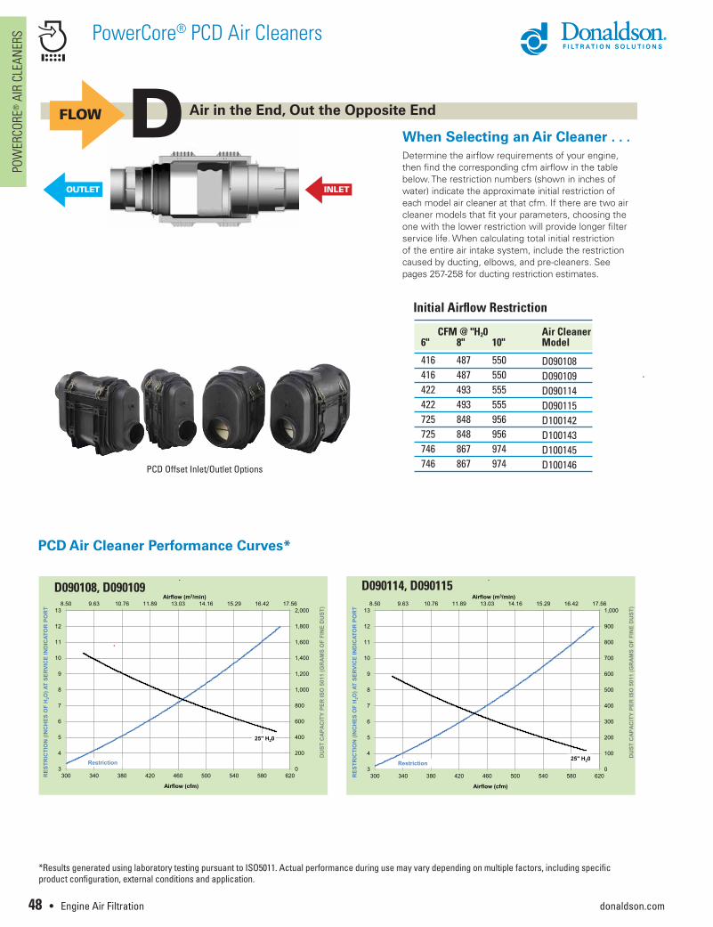
Initial Airflow Restriction
CFM @ "H20 Air Cleaner6" 8" 10" Model
416 487 550 D090108 416 487 550 D090109422 493 555 D090114 422 493 555 D090115725 848 956 D100142725 848 956 D100143 746 867 974 D100145 746 867 974 D100146
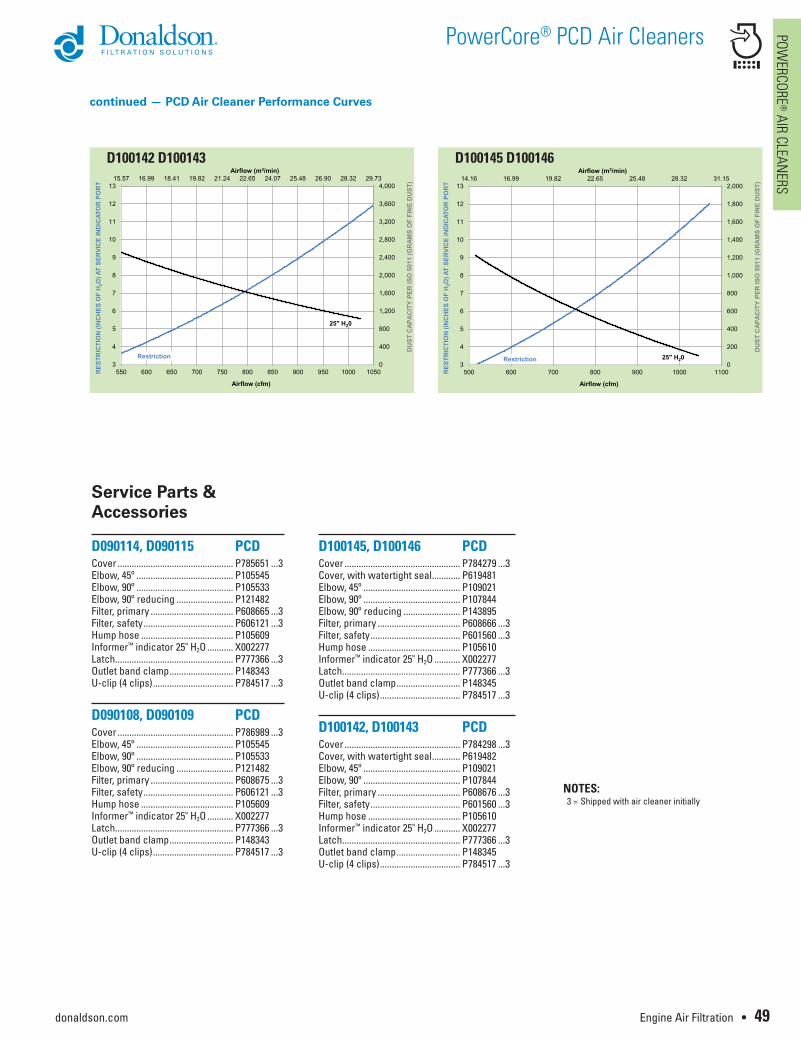
When Selecting an Air Cleaner . . .Determine the airflow requirements of your engine, then find the corresponding cfm airflow in the table below. The restriction numbers (shown in inches of water) indicate the approximate initial restriction of each model air cleaner at that cfm. If there are two air cleaner models that fit your parameters, choosing the one with the lower restriction will provide longer filter service life. When calculating total initial restriction of the entire air intake system, include the restriction caused by ducting, elbows, and pre-cleaners. See pages 257-258 for ducting restriction estimates.
D Air in the End, Out the Opposite End
PCD Air Cleaner Performance Curves*
FLOW
OUTLET INLET
D090108, D090109
0
200
400
600
800
1,000
1,200
1,400
1,600
1,800
2,0008.50 9.63 10.76 11.89 13.03 14.16 15.29 16.42 17.56
3
4
5
6
7
8
9
10
11
12
13
300 340 380 420 460 500 540 580 620
Airflow (m3/min)
RES
TRIC
TIO
N (I
NC
HES
OF
H2O
) AT
SER
VIC
E IN
DIC
ATO
R P
OR
T
Airflow (cfm)
DU
ST C
APA
CIT
Y PE
R IS
O 5
011
(GR
AMS
OF
FIN
E D
UST
)
Restriction
25" H20
PCD090108, PCD090109
2010 Donaldson Company Inc.
D090114, D090115
0
100
200
300
400
500
600
700
800
900
1,0008.50 9.63 10.76 11.89 13.03 14.16 15.29 16.42 17.56
3
4
5
6
7
8
9
10
11
12
13
300 340 380 420 460 500 540 580 620
Airflow (m3/min)
RES
TRIC
TIO
N (I
NC
HES
OF
H2O
) AT
SER
VIC
E IN
DIC
ATO
R P
OR
T
Airflow (cfm)
DU
ST C
APA
CIT
Y PE
R IS
O 5
011
(GR
AMS
OF
FIN
E D
UST
)
Restriction25" H20
PCD090114, PCD090115
2010 Donaldson Company Inc.
PCD Offset Inlet/Outlet Options
*Results generated using laboratory testing pursuant to ISO5011. Actual performance during use may vary depending on multiple factors, including specific product configuration, external conditions and application.
PowerCore® PCD Air Cleaners POWERCORE
® AIR CLEANERS
donaldson.com Engine Air Filtration • 49
continued — PCD Air Cleaner Performance Curves
D100142 D100143
0
400
800
1,200
1,600
2,000
2,400
2,800
3,200
3,600
4,00015.57 16.99 18.41 19.82 21.24 22.65 24.07 25.48 26.90 28.32 29.73
3
4
5
6
7
8
9
10
11
12
13
550 600 650 700 750 800 850 900 950 1000 1050
Airflow (m3/min)
RES
TRIC
TIO
N (I
NC
HES
OF
H2O
) AT
SER
VIC
E IN
DIC
ATO
R P
OR
T
Airflow (cfm)
DU
ST C
APA
CIT
Y PE
R IS
O 5
011
(GR
AMS
OF
FIN
E D
UST
)
Restriction
25" H20
PCD100142, PCD100143
2010 Donaldson Company Inc.
D100145 D100146
0
200
400
600
800
1,000
1,200
1,400
1,600
1,800
2,00014.16 16.99 19.82 22.65 25.48 28.32 31.15
3
4
5
6
7
8
9
10
11
12
13
500 600 700 800 900 1000 1100
Airflow (m3/min)
RES
TRIC
TIO
N (I
NC
HES
OF
H2O
) AT
SER
VIC
E IN
DIC
ATO
R P
OR
T
Airflow (cfm)
DU
ST C
APA
CIT
Y PE
R IS
O 5
011
(GR
AMS
OF
FIN
E D
UST
)
Restriction 25" H20
PCD100145, PCD100146
2010 Donaldson Company Inc.
Service Parts & Accessories
D090114, D090115 PCD Cover ................................................. P785651 ...3Elbow, 45º ......................................... P105545Elbow, 90º ......................................... P105533Elbow, 90º reducing ........................ P121482Filter, primary ................................... P608665 ...3Filter, safety ...................................... P606121 ...3Hump hose ....................................... P105609Informer™ indicator 25" H2O ........... X002277Latch.................................................. P777366 ...3Outlet band clamp ........................... P148343U-clip (4 clips) .................................. P784517 ...3
D090108, D090109 PCD Cover ................................................. P786989 ...3Elbow, 45º ......................................... P105545Elbow, 90º ......................................... P105533Elbow, 90º reducing ........................ P121482Filter, primary ................................... P608675 ...3Filter, safety ...................................... P606121 ...3Hump hose ....................................... P105609Informer™ indicator 25" H2O ........... X002277Latch.................................................. P777366 ...3Outlet band clamp ........................... P148343U-clip (4 clips) .................................. P784517 ...3
D100145, D100146 PCD Cover ................................................. P784279 ...3Cover, with watertight seal ............ P619481 Elbow, 45º ......................................... P109021Elbow, 90º ......................................... P107844Elbow, 90º reducing ........................ P143895Filter, primary ................................... P608666 ...3Filter, safety ...................................... P601560 ...3Hump hose ....................................... P105610Informer™ indicator 25" H2O ........... X002277Latch.................................................. P777366 ...3Outlet band clamp ........................... P148345U-clip (4 clips) .................................. P784517 ...3
D100142, D100143 PCD Cover ................................................. P784298 ...3Cover, with watertight seal ............ P619482 Elbow, 45º ......................................... P109021Elbow, 90º ......................................... P107844Filter, primary ................................... P608676 ...3Filter, safety ...................................... P601560 ...3Hump hose ....................................... P105610Informer™ indicator 25" H2O ........... X002277Latch.................................................. P777366 ...3Outlet band clamp ........................... P148345U-clip (4 clips) .................................. P784517 ...3
NOTES: 3 = Shipped with air cleaner initially
PowerCore® PCD Air Cleaners PO
WER
CORE
® A
IR C
LEAN
ERS
donaldson.com50 • Engine Air Filtration
Note: a minimum service clearance of 50mm (2.00") is required for wire latches.
H
B
E F
I
A
A
PCD09, PCD10
PCD09, PCD10 Specifications (Letters are keyed to drawings)
Inlet Orientation: I=Inline; O=Off-set
Service Part No. / A B C D E F G H Clearance (I) Weight Orientation mm in mm in mm in mm in mm in mm in mm in mm in mm in kg lbs
D090108 O 102 4.00 553 21.77 365 14.37 180 7.09 180 7.09 183 7.21 100 3.94 130 5.12 356 14.0 4.8 10.5D090109 I 102 4.00 553 21.77 365 14.37 180 7.09 180 7.09 183 7.21 100 3.94 130 5.12 356 14.0 4.8 10.5D090114 O 102 4.00 453 17.85 360 14.18 180 7.09 110 4.33 173 6.83 100 3.94 130 5.12 330 13.0 4.1 9.1D090115 I 102 4.00 453 17.85 360 14.18 180 7.09 110 4.33 173 7.21 100 3.94 130 5.12 330 13.0 4.1 9.1D100142 O 127 5.00 536 21.10 384 15.12 254 10.01 210 8.27 165 6.50 110 4.33 110 4.33 356 14.0 5.9 13.0D100143 I 127 5.00 536 21.10 384 15.12 254 10.01 210 8.27 165 6.50 110 4.33 110 4.33 356 14.0 5.9 13.0D100145 O 127 5.00 436 17.17 375 14.75 254 10.01 110 4.33 165 6.50 110 4.33 110 4.33 356 14.0 5.2 11.4D100146 I 127 5.00 436 17.17 375 14.75 254 10.01 110 4.33 165 6.50 110 4.33 110 4.33 356 14.0 5.2 11.4
G
C
D
PCD09 PCD10
PowerCore® PCD Air Cleaners POWERCORE
® AIR CLEANERS
donaldson.com Engine Air Filtration • 51
1
2
3
4
5
This servicing information is provided as a best practices guide. It is not intended to replace or supersede the service instructions supplied by your engine or vehicle manufacturer. Note: Your air cleaner service cover may be in a different position than shown.
Service Instructions
Check the Restriction Replace the filter only when the restriction level has reached the maximum recommended by the engine or equipment manufacturer or on a regular scheduled service.
Remove the Primary FilterPush down on the service handle to tilt the filter to a 5º angle. This will loosen the seal. Then, pull up on the service handle to remove the filter from the housing.
Visually Inspect the Safety Filter Remove any excess dirt and wipe out the housing with a damp cloth before servicing the safety filter. Visually inspect the safety filter but do not remove it unless it is damaged or due for change-out. Verify that the safety filter is properly seated in the housing. The safety filter should be replaced every three primary filter changes.
Remove Safety Filter if Indicated or if Excessively Contaminated To remove the safety filter, use the plastic handle on the face of the safety filter. Pull the filter toward the center of the housing and remove it. Ensure that the outlet tube sealing area is clean and undamaged. If the safety filter is removed and the new filter is not to be installed immediately, be sure to cover the seal tube with a cloth so that dirt is not admitted. After removing the safety filter, wipe the air cleaner housing interior and seal surfaces with a clean, damp cloth.
Inspect the New Filters Visually check for cuts, tears or indentations on the sealing surfaces and the media pack before installation. If any damage is visible, do not install.
NEVER use a pressure sprayer to clean out the air cleaner housing while it is installed on the machine.
The safety filter should be replaced every three primary filter changes.
Continued on next page
PowerCore® PCD Air Cleaners PO
WER
CORE
® A
IR C
LEAN
ERS
donaldson.com52 • Engine Air Filtration
7
8
9
6
Service Instructions
Insert the Primary Filter Slide the filter down at approximately a 5º angle until it makes contact with the end of the housing. Rotate the filter toward the outlet section to complete the seal.
Replace the Service Cover Place the service cover in position and fasten the metal latches. If the cover doesn’t seat, remove and re-check the filter position and access cover orientation.
Inspect the Entire Air Cleaner System Make sure that inlet and outlet connections are in good condition. Torque to and do not exceed 40 in• lb. Replace rubber connectors if necessary and reset the service indicator.
Replace the Safety Filter If replacing the safety filter, use the plastic handle. Slide the filter at an angle into the outlet side and push it in place until the filter seats firmly and evenly within the housing.