re: armstrong hardwood flooring company title v …dep.wv.gov/daq/permitting/documents/january...
TRANSCRIPT
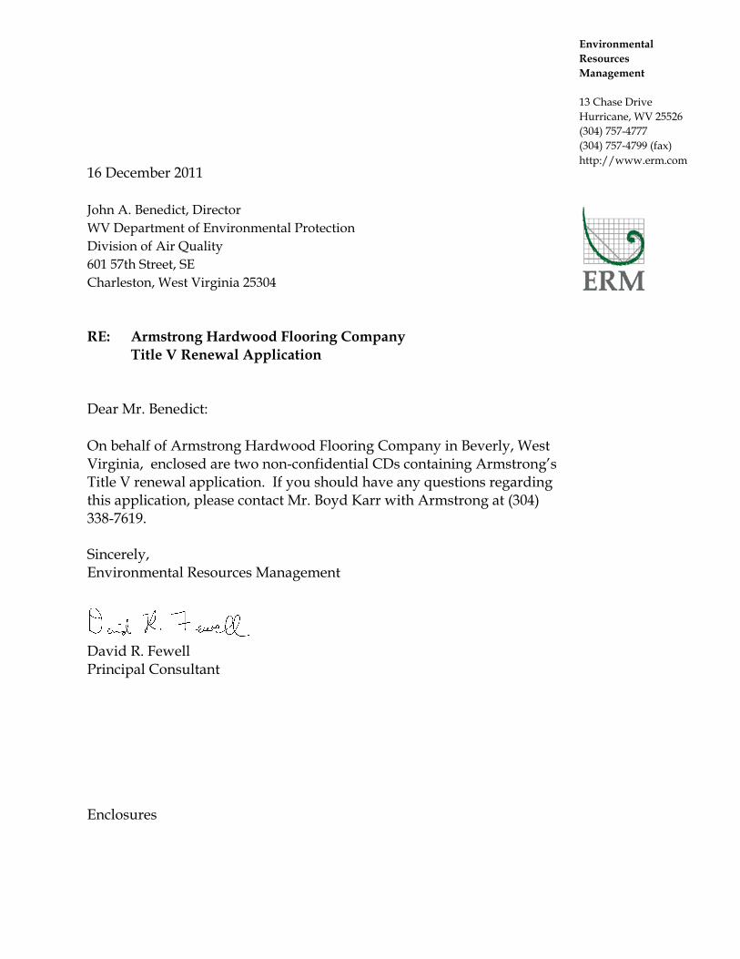
Environmental Resources Management
13 Chase Drive Hurricane, WV 25526 (304) 757-4777 (304) 757‐4799 (fax) http://www.erm.com
16 December 2011 John A. Benedict, Director WV Department of Environmental Protection Division of Air Quality 601 57th Street, SE Charleston, West Virginia 25304
RE: Armstrong Hardwood Flooring Company Title V Renewal Application Dear Mr. Benedict:
On behalf of Armstrong Hardwood Flooring Company in Beverly, West Virginia, enclosed are two non-confidential CDs containing Armstrong’s Title V renewal application. If you should have any questions regarding this application, please contact Mr. Boyd Karr with Armstrong at (304) 338-7619.
Sincerely, Environmental Resources Management
David R. Fewell Principal Consultant Enclosures

Armstrong Hardwood Flooring Company
Title V Renewal Permit Application
Beverly, West Virginia
Prepared By: ENVIRONMENTAL RESOURCES MANAGEMENT, Inc.
Hurricane, West Virginia December 2011
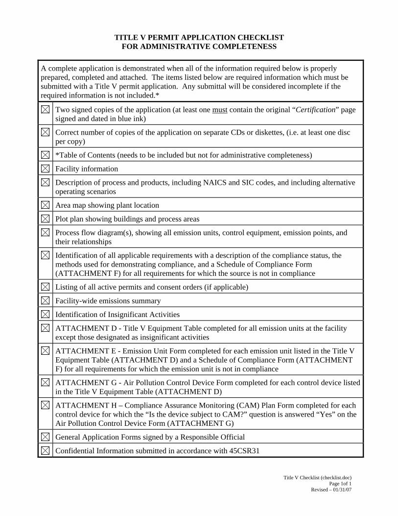
Title V Checklist (checklist.doc) Page 1of 1
Revised – 01/31/07
TITLE V PERMIT APPLICATION CHECKLIST FOR ADMINISTRATIVE COMPLETENESS
A complete application is demonstrated when all of the information required below is properly prepared, completed and attached. The items listed below are required information which must be submitted with a Title V permit application. Any submittal will be considered incomplete if the required information is not included.*
Two signed copies of the application (at least one must contain the original “Certification” page signed and dated in blue ink)
Correct number of copies of the application on separate CDs or diskettes, (i.e. at least one disc per copy)
*Table of Contents (needs to be included but not for administrative completeness)
Facility information
Description of process and products, including NAICS and SIC codes, and including alternative operating scenarios
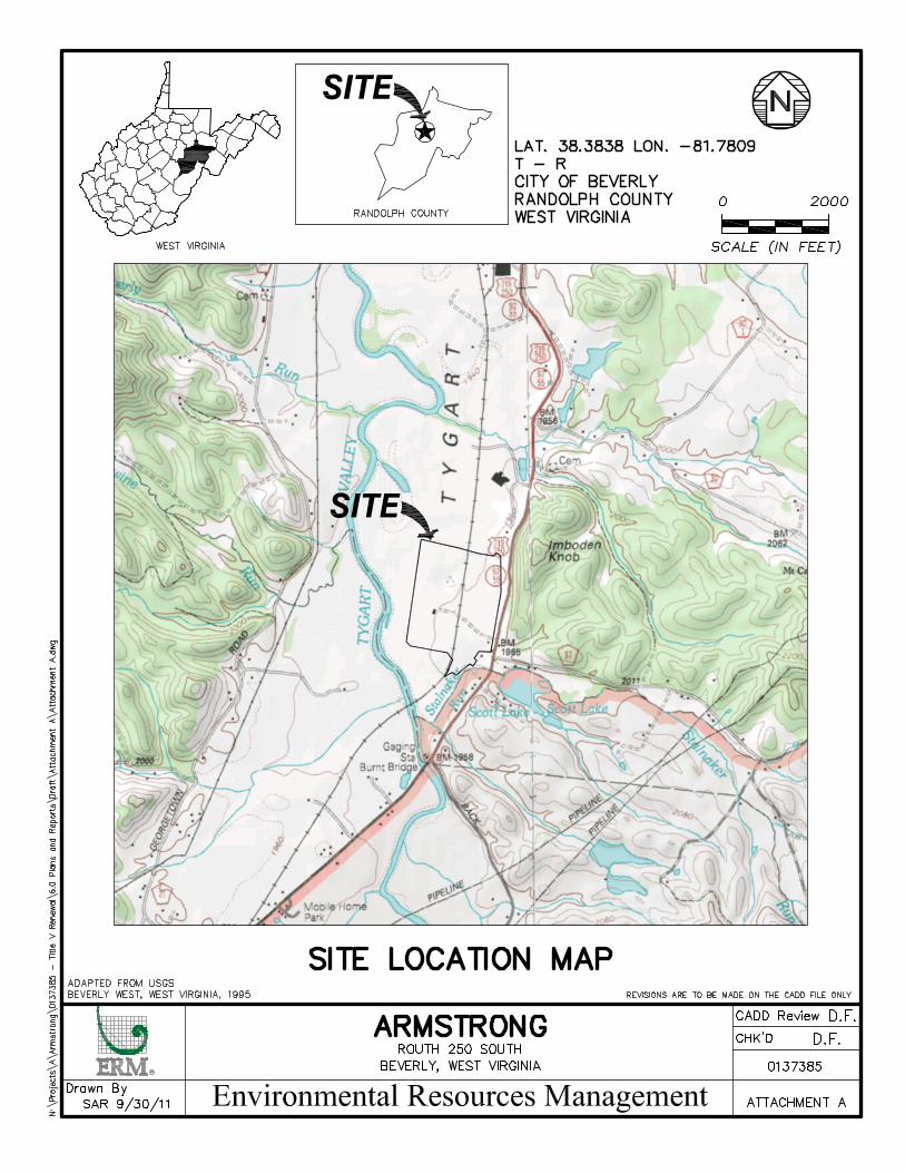
Area map showing plant location
Plot plan showing buildings and process areas
Process flow diagram(s), showing all emission units, control equipment, emission points, and their relationships
Identification of all applicable requirements with a description of the compliance status, the methods used for demonstrating compliance, and a Schedule of Compliance Form (ATTACHMENT F) for all requirements for which the source is not in compliance
Listing of all active permits and consent orders (if applicable)
Facility-wide emissions summary
Identification of Insignificant Activities
ATTACHMENT D - Title V Equipment Table completed for all emission units at the facility except those designated as insignificant activities
ATTACHMENT E - Emission Unit Form completed for each emission unit listed in the Title V Equipment Table (ATTACHMENT D) and a Schedule of Compliance Form (ATTACHMENT F) for all requirements for which the emission unit is not in compliance
ATTACHMENT G - Air Pollution Control Device Form completed for each control device listed in the Title V Equipment Table (ATTACHMENT D)
ATTACHMENT H – Compliance Assurance Monitoring (CAM) Plan Form completed for each control device for which the “Is the device subject to CAM?” question is answered “Yes” on the Air Pollution Control Device Form (ATTACHMENT G)
General Application Forms signed by a Responsible Official
Confidential Information submitted in accordance with 45CSR31
Page 1 of 14
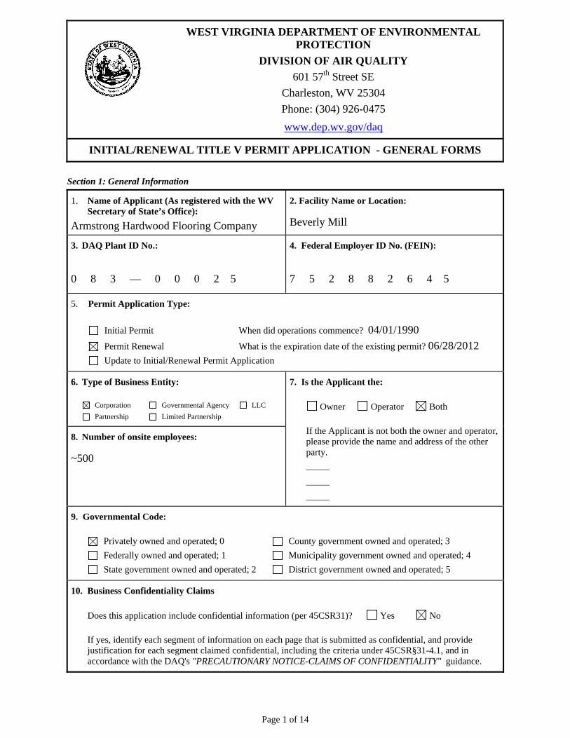
WEST VIRGINIA DEPARTMENT OF ENVIRONMENTAL PROTECTION
DIVISION OF AIR QUALITY
601 57th Street SE
Charleston, WV 25304
Phone: (304) 926-0475
www.dep.wv.gov/daq
INITIAL/RENEWAL TITLE V PERMIT APPLICATION - GENERAL FORMS
Section 1: General Information
1. Name of Applicant (As registered with the WV Secretary of State’s Office):
Armstrong Hardwood Flooring Company
2. Facility Name or Location:
Beverly Mill
3. DAQ Plant ID No.:
0 8 3 — 0 0 0 2 5
4. Federal Employer ID No. (FEIN):
7 5 2 8 8 2 6 4 5
5. Permit Application Type:
Initial Permit When did operations commence? 04/01/1990
Permit Renewal What is the expiration date of the existing permit? 06/28/2012
Update to Initial/Renewal Permit Application
6. Type of Business Entity:
Corporation Governmental Agency LLC
Partnership Limited Partnership
8. Number of onsite employees:
~500
7. Is the Applicant the:
Owner Operator Both
If the Applicant is not both the owner and operator, please provide the name and address of the other party.
9. Governmental Code:
Privately owned and operated; 0 County government owned and operated; 3
Federally owned and operated; 1 Municipality government owned and operated; 4
State government owned and operated; 2 District government owned and operated; 5
10. Business Confidentiality Claims
Does this application include confidential information (per 45CSR31)? Yes No
If yes, identify each segment of information on each page that is submitted as confidential, and provide justification for each segment claimed confidential, including the criteria under 45CSR§31-4.1, and in accordance with the DAQ's "PRECAUTIONARY NOTICE-CLAIMS OF CONFIDENTIALITY" guidance.
Page 2 of 14
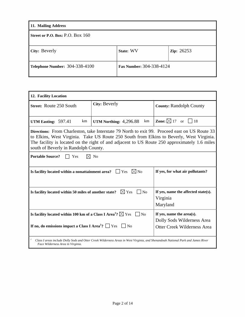
11. Mailing Address
Street or P.O. Box: P.O. Box 160
City: Beverly
State: WV
Zip: 26253
Telephone Number: 304-338-4100
Fax Number: 304-338-4124
12. Facility Location
Street: Route 250 South
City: Beverly County: Randolph County
UTM Easting: 597.41 km UTM Northing: 4,296.88 km Zone: 17 or 18
Directions: From Charleston, take Interstate 79 North to exit 99. Proceed east on US Route 33 to Elkins, West Virginia. Take US Route 250 South from Elkins to Beverly, West Virginia. The facility is located on the right of and adjacent to US Route 250 approximately 1.6 miles south of Beverly in Randolph County.
Portable Source? Yes No
Is facility located within a nonattainment area? Yes No
If yes, for what air pollutants?
Is facility located within 50 miles of another state? Yes No
If yes, name the affected state(s).
Virginia
Maryland
Is facility located within 100 km of a Class I Area1? Yes No
If no, do emissions impact a Class I Area1? Yes No
If yes, name the area(s).
Dolly Sods Wilderness Area
Otter Creek Wilderness Area
1 Class I areas include Dolly Sods and Otter Creek Wilderness Areas in West Virginia, and Shenandoah National Park and James River Face Wilderness Area in Virginia.
Page 3 of 14
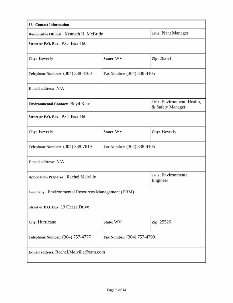
13. Contact Information
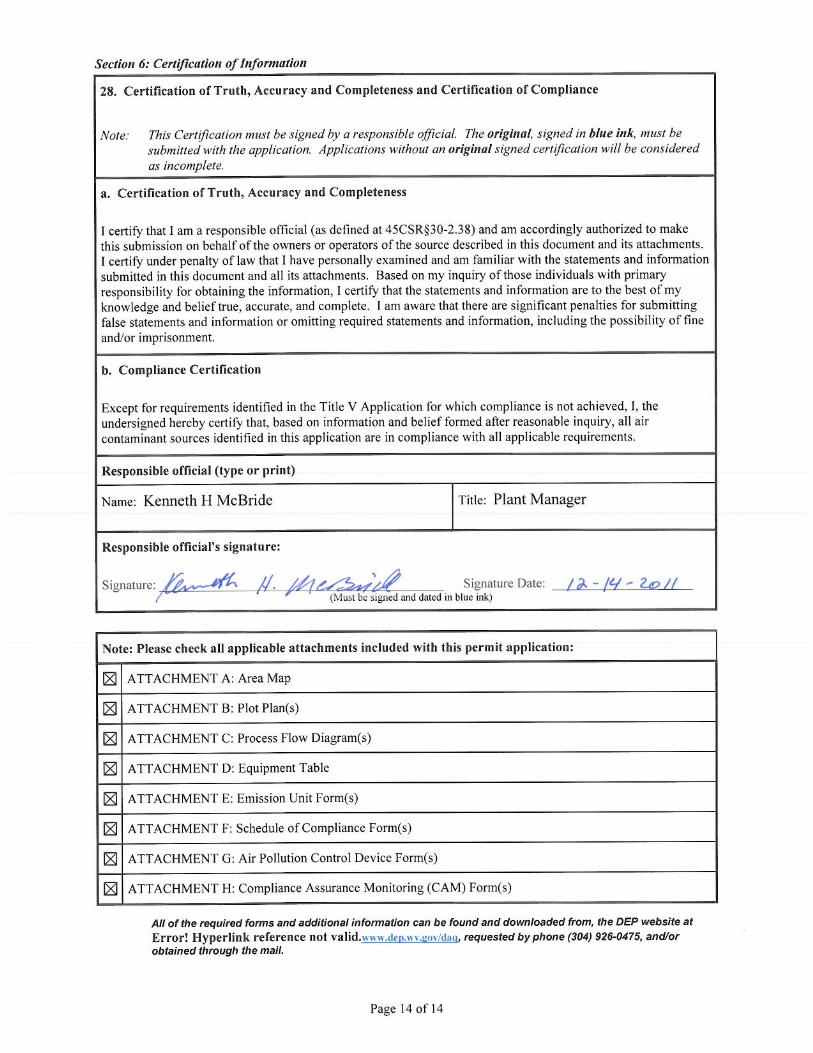
Responsible Official: Kenneth H. McBride Title: Plant Manager
Street or P.O. Box: P.O. Box 160
City: Beverly
State: WV
Zip: 26253
Telephone Number: (304) 338-4100
Fax Number: (304) 338-4105
E-mail address: N/A
Environmental Contact: Boyd Karr Title: Environment, Health, & Safety Manager
Street or P.O. Box: P.O. Box 160
City: Beverly
State: WV
City: Beverly
Telephone Number: (304) 338-7619
Fax Number: (304) 338-4105
E-mail address: N/A
Application Preparer: Rachel Melville
Title: Environmental Engineer
Company: Environmental Resources Management (ERM)
Street or P.O. Box: 13 Chase Drive
City: Hurricane
State: WV Zip: 25526
Telephone Number: (304) 757-4777
Fax Number: (304) 757-4799
E-mail address: [email protected]
Page 4 of 14
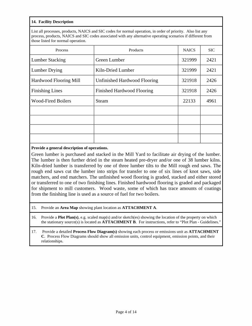
14. Facility Description
List all processes, products, NAICS and SIC codes for normal operation, in order of priority. Also list any process, products, NAICS and SIC codes associated with any alternative operating scenarios if different from those listed for normal operation.
Process Products NAICS SIC
Lumber Stacking Green Lumber 321999 2421
Lumber Drying Kiln-Dried Lumber 321999 2421
Hardwood Flooring Mill Unfinished Hardwood Flooring 321918 2426
Finishing Lines Finished Hardwood Flooring 321918 2426
Wood-Fired Boilers Steam 22133 4961
Provide a general description of operations.
Green lumber is purchased and stacked in the Mill Yard to facilitate air drying of the lumber. The lumber is then further dried in the steam heated pre-dryer and/or one of 38 lumber kilns. Kiln-dried lumber is transferred by one of three lumber tilts to the Mill rough end saws. The rough end saws cut the lumber into strips for transfer to one of six lines of knot saws, side matchers, and end matchers. The unfinished wood flooring is graded, stacked and either stored or transferred to one of two finishing lines. Finished hardwood flooring is graded and packaged for shipment to mill customers. Wood waste, some of which has trace amounts of coatings from the finishing line is used as a source of fuel for two boilers.
15. Provide an Area Map showing plant location as ATTACHMENT A.
16. Provide a Plot Plan(s), e.g. scaled map(s) and/or sketch(es) showing the location of the property on which the stationary source(s) is located as ATTACHMENT B. For instructions, refer to “Plot Plan - Guidelines.”
17. Provide a detailed Process Flow Diagram(s) showing each process or emissions unit as ATTACHMENT C. Process Flow Diagrams should show all emission units, control equipment, emission points, and their relationships.
Page 5 of 14
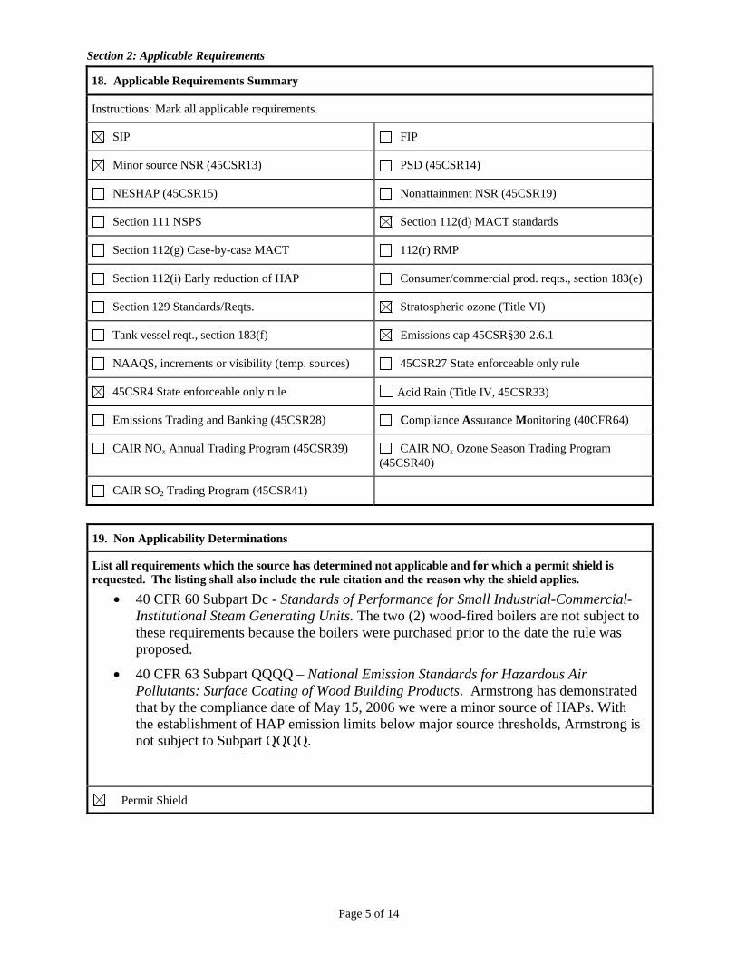
Section 2: Applicable Requirements
18. Applicable Requirements Summary
Instructions: Mark all applicable requirements.
SIP FIP
Minor source NSR (45CSR13) PSD (45CSR14)
NESHAP (45CSR15) Nonattainment NSR (45CSR19)
Section 111 NSPS Section 112(d) MACT standards
Section 112(g) Case-by-case MACT 112(r) RMP
Section 112(i) Early reduction of HAP Consumer/commercial prod. reqts., section 183(e)
Section 129 Standards/Reqts. Stratospheric ozone (Title VI)
Tank vessel reqt., section 183(f) Emissions cap 45CSR§30-2.6.1
NAAQS, increments or visibility (temp. sources) 45CSR27 State enforceable only rule
45CSR4 State enforceable only rule Acid Rain (Title IV, 45CSR33)
Emissions Trading and Banking (45CSR28) Compliance Assurance Monitoring (40CFR64)
CAIR NOx Annual Trading Program (45CSR39) CAIR NOx Ozone Season Trading Program (45CSR40)
CAIR SO2 Trading Program (45CSR41)
19. Non Applicability Determinations
List all requirements which the source has determined not applicable and for which a permit shield is requested. The listing shall also include the rule citation and the reason why the shield applies.
40 CFR 60 Subpart Dc - Standards of Performance for Small Industrial-Commercial-Institutional Steam Generating Units. The two (2) wood-fired boilers are not subject to these requirements because the boilers were purchased prior to the date the rule was proposed.
40 CFR 63 Subpart QQQQ – National Emission Standards for Hazardous Air Pollutants: Surface Coating of Wood Building Products. Armstrong has demonstrated that by the compliance date of May 15, 2006 we were a minor source of HAPs. With the establishment of HAP emission limits below major source thresholds, Armstrong is not subject to Subpart QQQQ.
Permit Shield
Page 6 of 14
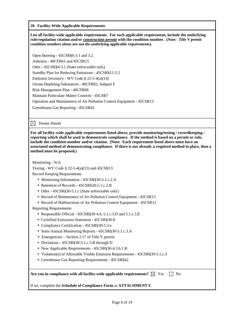
20. Facility-Wide Applicable Requirements
List all facility-wide applicable requirements. For each applicable requirement, include the underlying rule/regulation citation and/or construction permit with the condition number. (Note: Title V permit condition numbers alone are not the underlying applicable requirements).
Open Burning - 45CSR§6-3.1 and 3.2
Asbestos - 40CFR61 and 45CSR15
Odor - 45CSR§4-3.1 (State enforceable only)
Standby Plan for Reducing Emissions - 45CSR§11-5.2
Emission Inventory - WV Code § 22-5-4(a)(14)
Ozone-Depleting Substances - 40CFR82, Subpart F
Risk Management Plan - 40CFR68
Maintain Particulate Matter Controls - 45CSR7
Operation and Maintanence of Air Pollution Control Equipment - 45CSR13
Greenhouse Gas Reporting - 45CSR42
Permit Shield
For all facility-wide applicable requirements listed above, provide monitoring/testing / recordkeeping / reporting which shall be used to demonstrate compliance. If the method is based on a permit or rule, include the condition number and/or citation. (Note: Each requirement listed above must have an associated method of demonstrating compliance. If there is not already a required method in place, then a method must be proposed.)
Monitoring - N/A
Testing - WV Code § 22-5-4(a)(15) and 45CSR13
Record Keeping Requirements
Monitoring Information - 45CSR§30-5.1.c.2.A
Retention of Records - 45CSR§30-5.1.c.2.B
Odor - 45CSR§30-5.1.c (State enforceable only)
Record of Maintenance of Air Pollution Control Equipment - 45CSR13
Record of Malfunctions of Air Pollution Control Equipment - 45CSR13
Reporting Requirements
Responsible Official - 45CSR§30-4.4, 5.1.c.3.D and 5.1.c.3.E
Ceritified Emissions Statement - 45CSR§30-8
Compliance Certification - 45CSR§30-5.3.e
Semi-Annual Monitoring Reports - 45CSR§30-5.1.c.3.A
Emergencies – Section 2.17 of Title V permit.
Deviations - 45CSR§30-5.1.c.3.B through D
New Applicable Requirements - 45CSR§30-4.3.h.1.B
Violation(s) of Allowable Visible Emission Requirements - 45CSR§30-5.1.c.3
Greenhouse Gas Reporting Requirements - 45CSR§42
Are you in compliance with all facility-wide applicable requirements? Yes No
If no, complete the Schedule of Compliance Form as ATTACHMENT F.
Page 7 of 14
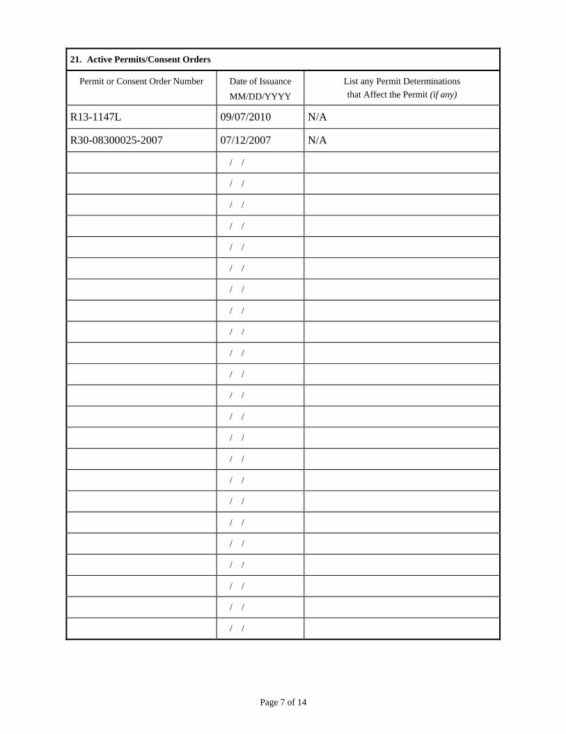
21. Active Permits/Consent Orders
Permit or Consent Order Number Date of Issuance
MM/DD/YYYY
List any Permit Determinations
that Affect the Permit (if any)
R13-1147L 09/07/2010 N/A
R30-08300025-2007 07/12/2007 N/A
/ /
/ /
/ /
/ /
/ /
/ /
/ /
/ /
/ /
/ /
/ /
/ /
/ /
/ /
/ /
/ /
/ /
/ /
/ /
/ /
/ /
/ /
/ /
Page 8 of 14
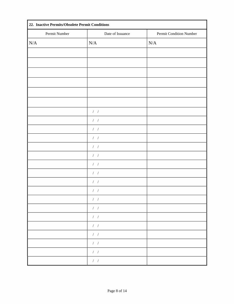
22. Inactive Permits/Obsolete Permit Conditions
Permit Number Date of Issuance Permit Condition Number
N/A N/A N/A
/ /
/ /
/ /
/ /
/ /
/ /
/ /
/ /
/ /
/ /
/ /
/ /
/ /
/ /
/ /
/ /
/ /
/ /
Page 9 of 14
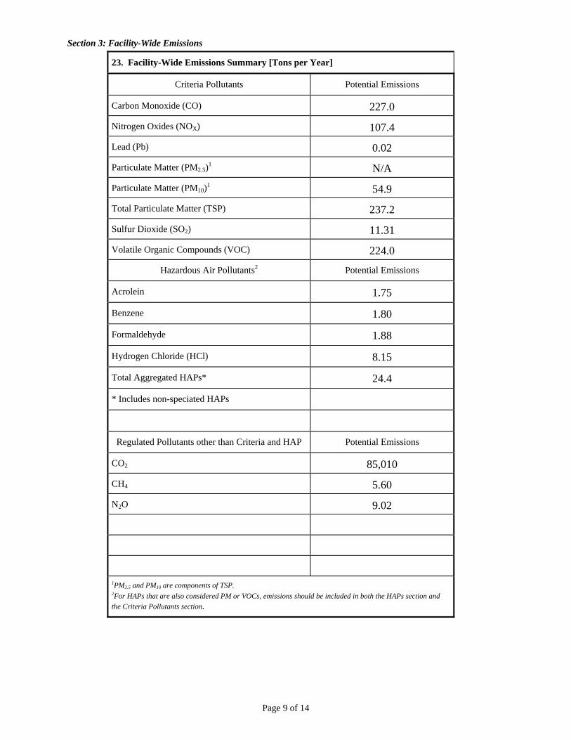
Section 3: Facility-Wide Emissions
23. Facility-Wide Emissions Summary [Tons per Year]
Criteria Pollutants Potential Emissions
Carbon Monoxide (CO) 227.0
Nitrogen Oxides (NOX) 107.4
Lead (Pb) 0.02
Particulate Matter (PM2.5)1 N/A
Particulate Matter (PM10)1 54.9
Total Particulate Matter (TSP) 237.2
Sulfur Dioxide (SO2) 11.31
Volatile Organic Compounds (VOC) 224.0
Hazardous Air Pollutants2 Potential Emissions
Acrolein 1.75
Benzene 1.80
Formaldehyde 1.88
Hydrogen Chloride (HCl) 8.15
Total Aggregated HAPs* 24.4
* Includes non-speciated HAPs
Regulated Pollutants other than Criteria and HAP Potential Emissions
CO2 85,010
CH4 5.60
N2O 9.02
1PM2.5 and PM10 are components of TSP. 2For HAPs that are also considered PM or VOCs, emissions should be included in both the HAPs section and
the Criteria Pollutants section.
Page 10 of 14
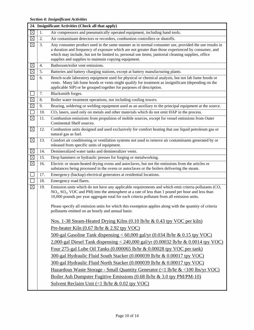
Section 4: Insignificant Activities 24. Insignificant Activities (Check all that apply)
1. Air compressors and pneumatically operated equipment, including hand tools.
2. Air contaminant detectors or recorders, combustion controllers or shutoffs.
3. Any consumer product used in the same manner as in normal consumer use, provided the use results in a duration and frequency of exposure which are not greater than those experienced by consumer, and which may include, but not be limited to, personal use items; janitorial cleaning supplies, office supplies and supplies to maintain copying equipment.
4. Bathroom/toilet vent emissions.
5. Batteries and battery charging stations, except at battery manufacturing plants.
6. Bench-scale laboratory equipment used for physical or chemical analysis, but not lab fume hoods or vents. Many lab fume hoods or vents might qualify for treatment as insignificant (depending on the applicable SIP) or be grouped together for purposes of description.
7. Blacksmith forges.
8. Boiler water treatment operations, not including cooling towers.
9. Brazing, soldering or welding equipment used as an auxiliary to the principal equipment at the source.
10. CO2 lasers, used only on metals and other materials which do not emit HAP in the process.
11. Combustion emissions from propulsion of mobile sources, except for vessel emissions from Outer Continental Shelf sources.
12. Combustion units designed and used exclusively for comfort heating that use liquid petroleum gas or natural gas as fuel.
13. Comfort air conditioning or ventilation systems not used to remove air contaminants generated by or released from specific units of equipment.
14. Demineralized water tanks and demineralizer vents.
15. Drop hammers or hydraulic presses for forging or metalworking.
16. Electric or steam-heated drying ovens and autoclaves, but not the emissions from the articles or substances being processed in the ovens or autoclaves or the boilers delivering the steam.
17. Emergency (backup) electrical generators at residential locations.
18. Emergency road flares.
19. Emission units which do not have any applicable requirements and which emit criteria pollutants (CO, NOx, SO2, VOC and PM) into the atmosphere at a rate of less than 1 pound per hour and less than 10,000 pounds per year aggregate total for each criteria pollutant from all emission units. Please specify all emission units for which this exemption applies along with the quantity of criteria pollutants emitted on an hourly and annual basis: Nos. 1-38 Steam-Heated Drying Kilns (0.10 lb/hr & 0.43 tpy VOC per kiln)
Pre-heater Kiln (0.67 lb/hr & 2.92 tpy VOC)
500-gal Gasoline Tank dispensing < 60,000 gal/yr (0.034 lb/hr & 0.15 tpy VOC)
2,000-gal Diesel Tank dispensing < 240,000 gal/yr (0.00032 lb/hr & 0.0014 tpy VOC)
Four 275-gal Lube Oil Tanks (0.000065 lb/hr & 0.00028 tpy VOC per tank)
300-gal Hydraulic Fluid South Stacker (0.000039 lb/hr & 0.00017 tpy VOC)
300-gal Hydraulic Fluid North Stacker (0.000039 lb/hr & 0.00017 tpy VOC)
Hazardous Waste Storage - Small Quantity Generator (<1 lb/hr & <100 lbs/yr VOC)
Boiler Ash Dumpster Fugitive Emissions (0.68 lb/hr & 3.0 tpy PM/PM-10)
Solvent Reclaim Unit (<1 lb/hr & 0.02 tpy VOC)
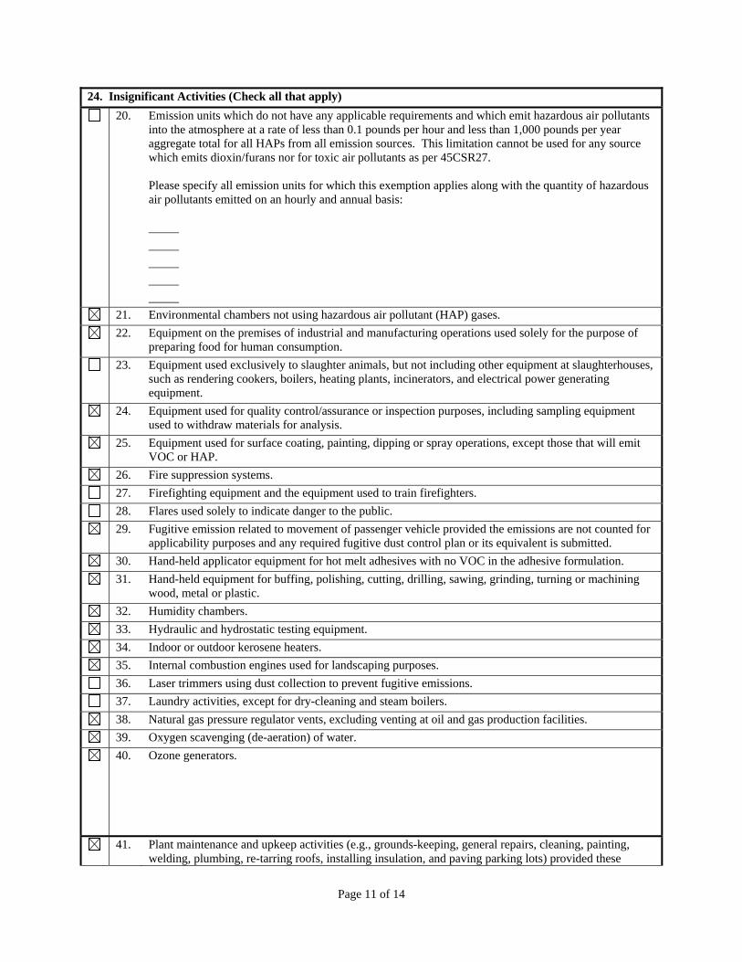
Page 11 of 14
24. Insignificant Activities (Check all that apply)
20. Emission units which do not have any applicable requirements and which emit hazardous air pollutants into the atmosphere at a rate of less than 0.1 pounds per hour and less than 1,000 pounds per year aggregate total for all HAPs from all emission sources. This limitation cannot be used for any source which emits dioxin/furans nor for toxic air pollutants as per 45CSR27. Please specify all emission units for which this exemption applies along with the quantity of hazardous air pollutants emitted on an hourly and annual basis:
21. Environmental chambers not using hazardous air pollutant (HAP) gases.
22. Equipment on the premises of industrial and manufacturing operations used solely for the purpose of preparing food for human consumption.
23. Equipment used exclusively to slaughter animals, but not including other equipment at slaughterhouses, such as rendering cookers, boilers, heating plants, incinerators, and electrical power generating equipment.
24. Equipment used for quality control/assurance or inspection purposes, including sampling equipment used to withdraw materials for analysis.
25. Equipment used for surface coating, painting, dipping or spray operations, except those that will emit VOC or HAP.
26. Fire suppression systems.
27. Firefighting equipment and the equipment used to train firefighters.
28. Flares used solely to indicate danger to the public.
29. Fugitive emission related to movement of passenger vehicle provided the emissions are not counted for applicability purposes and any required fugitive dust control plan or its equivalent is submitted.
30. Hand-held applicator equipment for hot melt adhesives with no VOC in the adhesive formulation.
31. Hand-held equipment for buffing, polishing, cutting, drilling, sawing, grinding, turning or machining wood, metal or plastic.
32. Humidity chambers.
33. Hydraulic and hydrostatic testing equipment.
34. Indoor or outdoor kerosene heaters.
35. Internal combustion engines used for landscaping purposes.
36. Laser trimmers using dust collection to prevent fugitive emissions.
37. Laundry activities, except for dry-cleaning and steam boilers.
38. Natural gas pressure regulator vents, excluding venting at oil and gas production facilities.
39. Oxygen scavenging (de-aeration) of water.
40. Ozone generators.
41. Plant maintenance and upkeep activities (e.g., grounds-keeping, general repairs, cleaning, painting, welding, plumbing, re-tarring roofs, installing insulation, and paving parking lots) provided these
Page 12 of 14
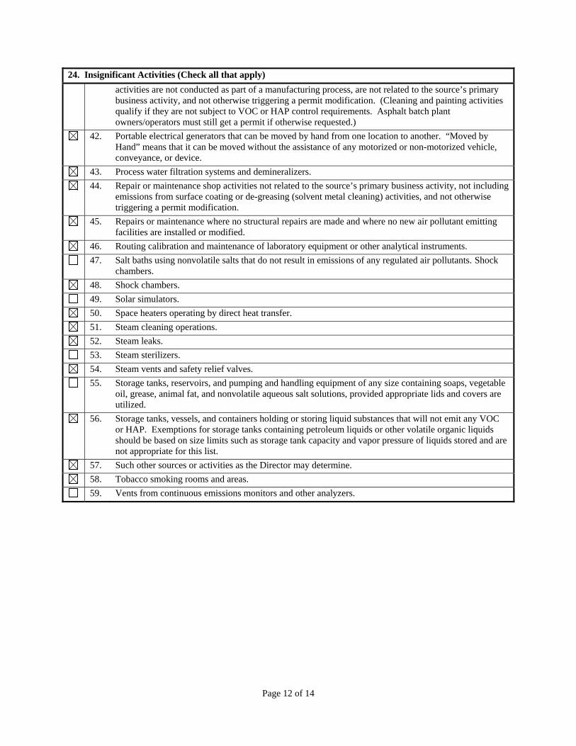
24. Insignificant Activities (Check all that apply)
activities are not conducted as part of a manufacturing process, are not related to the source’s primary business activity, and not otherwise triggering a permit modification. (Cleaning and painting activities qualify if they are not subject to VOC or HAP control requirements. Asphalt batch plant owners/operators must still get a permit if otherwise requested.)
42. Portable electrical generators that can be moved by hand from one location to another. “Moved by Hand” means that it can be moved without the assistance of any motorized or non-motorized vehicle, conveyance, or device.
43. Process water filtration systems and demineralizers.
44. Repair or maintenance shop activities not related to the source’s primary business activity, not including emissions from surface coating or de-greasing (solvent metal cleaning) activities, and not otherwise triggering a permit modification.
45. Repairs or maintenance where no structural repairs are made and where no new air pollutant emitting facilities are installed or modified.
46. Routing calibration and maintenance of laboratory equipment or other analytical instruments.
47. Salt baths using nonvolatile salts that do not result in emissions of any regulated air pollutants. Shock chambers.
48. Shock chambers.
49. Solar simulators.
50. Space heaters operating by direct heat transfer.
51. Steam cleaning operations.
52. Steam leaks.
53. Steam sterilizers.
54. Steam vents and safety relief valves.
55. Storage tanks, reservoirs, and pumping and handling equipment of any size containing soaps, vegetable oil, grease, animal fat, and nonvolatile aqueous salt solutions, provided appropriate lids and covers are utilized.
56. Storage tanks, vessels, and containers holding or storing liquid substances that will not emit any VOC or HAP. Exemptions for storage tanks containing petroleum liquids or other volatile organic liquids should be based on size limits such as storage tank capacity and vapor pressure of liquids stored and are not appropriate for this list.
57. Such other sources or activities as the Director may determine.
58. Tobacco smoking rooms and areas.
59. Vents from continuous emissions monitors and other analyzers.
Page 13 of 14
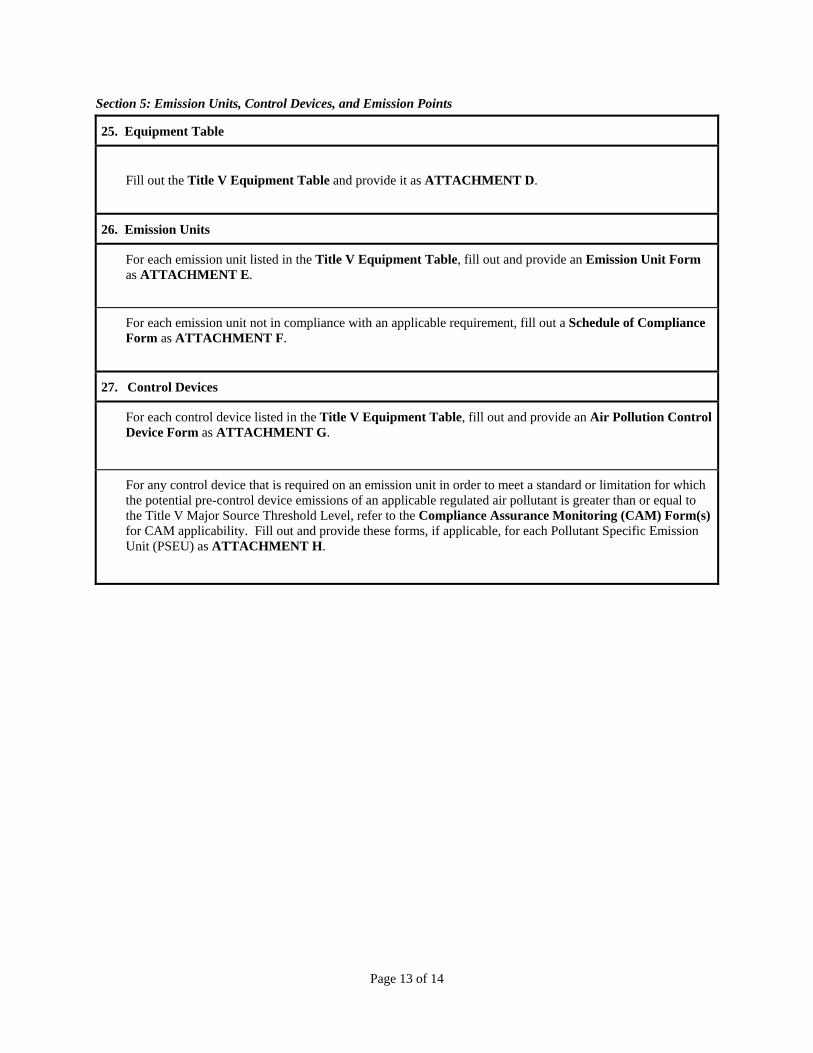
Section 5: Emission Units, Control Devices, and Emission Points
25. Equipment Table
Fill out the Title V Equipment Table and provide it as ATTACHMENT D.
26. Emission Units
For each emission unit listed in the Title V Equipment Table, fill out and provide an Emission Unit Form as ATTACHMENT E.
For each emission unit not in compliance with an applicable requirement, fill out a Schedule of Compliance Form as ATTACHMENT F.
27. Control Devices
For each control device listed in the Title V Equipment Table, fill out and provide an Air Pollution Control Device Form as ATTACHMENT G.
For any control device that is required on an emission unit in order to meet a standard or limitation for which the potential pre-control device emissions of an applicable regulated air pollutant is greater than or equal to the Title V Major Source Threshold Level, refer to the Compliance Assurance Monitoring (CAM) Form(s) for CAM applicability. Fill out and provide these forms, if applicable, for each Pollutant Specific Emission Unit (PSEU) as ATTACHMENT H.
Attachment A
Area Map
Attachment B
Plot Plan
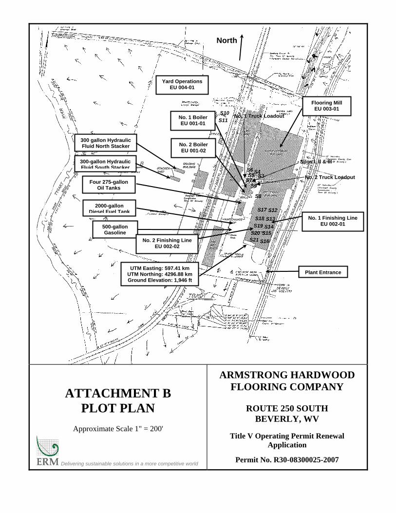
ATTACHMENT B PLOT PLAN
Approximate Scale 1" = 200'
Delivering sustainable solutions in a more competitive world
ARMSTRONG HARDWOOD FLOORING COMPANY
ROUTE 250 SOUTH
BEVERLY, WV
Title V Operating Permit Renewal Application
Permit No. R30-08300025-2007
North
No. 1 Boiler EU 001-01
Four 275-gallon Oil Tanks
500-gallon Gasoline
2000-gallon Diesel Fuel Tank
300 gallon Hydraulic Fluid North Stacker
300-gallon Hydraulic Fluid South Stacker
No. 1 Finishing Line EU 002-01
Plant Entrance
Flooring Mill EU 003-01
UTM Easting: 597.41 km UTM Northing: 4296.88 km Ground Elevation: 1,946 ft
No. 2 Finishing Line EU 002-02
No. 2 Boiler EU 001-02
S11
No. 2 Truck Loadout
S19
S18
S17
S14 S15
S16
S20 S21
S13
S12
S34 S
S5 S7
S9
S6
S8
Silos I, II & III
No. 1 Truck Loadout
Yard Operations EU 004-01
S10
Attachment C
Process Flow Diagrams
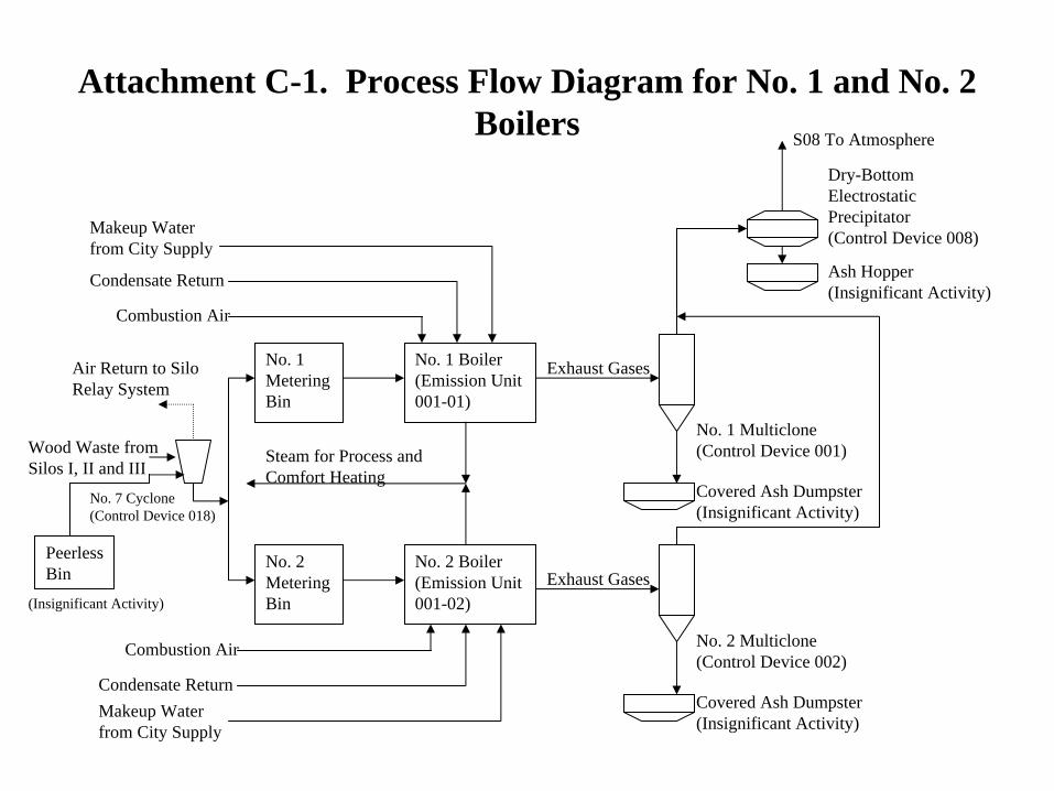
Attachment C-1. Process Flow Diagram for No. 1 and No. 2 Boilers
No. 1 Boiler (Emission Unit 001-01)
No. 2 Boiler (Emission Unit 001-02)
No. 1 Metering Bin
No. 2 Metering Bin
Combustion Air
Condensate Return
Combustion Air
Condensate Return
Steam for Process and Comfort Heating
Wood Waste from Silos I, II and III
Exhaust Gases
No. 1 Multiclone (Control Device 001)
Covered Ash Dumpster (Insignificant Activity)
Exhaust Gases
No. 2 Multiclone (Control Device 002)
Ash Hopper (Insignificant Activity)
Dry-Bottom Electrostatic Precipitator (Control Device 008)
S08 To Atmosphere
Covered Ash Dumpster (Insignificant Activity)
Makeup Water from City Supply
Makeup Water from City Supply
No. 7 Cyclone (Control Device 018)
Air Return to Silo Relay System
Peerless Bin
(Insignificant Activity)
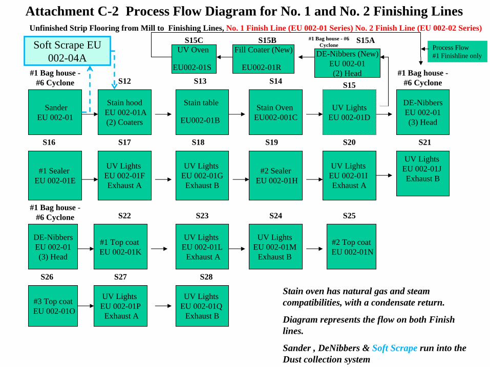
SanderEU 002-01
Stain hoodEU 002-01A(2) Coaters
Stain table
EU002-01B
Stain Oven EU002-001C
UV LightsEU 002-01D
#1 Sealer EU 002-01E
UV Lights EU 002-01FExhaust A
UV Lights EU 002-01GExhaust B
#2 SealerEU 002-01H
UV Lights EU 002-01J Exhaust B
UV Lights EU 002-01I Exhaust A
#1 Top coat EU 002-01K
UV Lights EU 002-01L
Exhaust A
UV Lights EU 002-01M
Exhaust B
#2 Top coatEU 002-01N
#3 Top coatEU 002-01O
UV Lights EU 002-01P
Exhaust A
Attachment C-2 Process Flow Diagram for No. 1 and No. 2 Finishing LinesUnfinished Strip Flooring from Mill to Finishing Lines, No. 1 Finish Line (EU 002-01 Series) No. 2 Finish Line (EU 002-02 Series)
UV Lights EU 002-01Q
Exhaust B
#1 Bag house - #6 Cyclone S12 S13 S14 S15
S16 S17 S18 S19 S20 S21
S22 S23 S24 S25
S26 S27 S28
Stain oven has natural gas and steam compatibilities, with a condensate return.
Diagram represents the flow on both Finish lines.
Sander , DeNibbers & Soft Scrape run into the Dust collection system
DE-NibbersEU 002-01(3) Head
#1 Bag house - #6 Cyclone
DE-NibbersEU 002-01(3) Head
#1 Bag house - #6 Cyclone
Fill Coater (New)
EU002-01R
UV Oven
EU002-01S
DE-Nibbers (New)EU 002-01(2) Head #1 Bag house -
#6 Cyclone
Process Flow #1 Finishline only
S15BS15C S15ASoft Scrape EU 002-04A
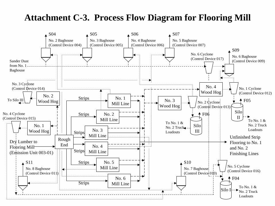
Attachment C-3. Process Flow Diagram for Flooring Mill
Rough End
Dry Lumber to Flooring Mill (Emission Unit 003-01)
No. 3 Mill Line
No. 3 Wood Hog
Unfinished Strip Flooring to No. 1 and No. 2 Finishing Lines
No. 2 Baghouse (Control Device 004)
S04
No. 4 Mill Line
No. 2 Mill Line
No. 1 Mill Line
No. 5 Mill Line
No. 6 Mill Line
Strips
Strips
Strips
Strips
Strips
Strips
No. 3 Baghouse (Control Device 005)
S05No. 4 Baghouse (Control Device 006)
S06No. 5 Baghouse (Control Device 007)
S07
No. 2 Cyclone (Control Device 013)
Silo III
F06
No. 2 Wood Hog
No. 3 Cyclone (Control Device 014)
No. 6 Baghouse (Control Device 009)
S09
Sander Dust from No. 1 Baghouse
No. 8 Baghouse (Control Device 011)
S11No. 7 Baghouse (Control Device 010)
S10No. 5 Cyclone (Control Device 016)
Silo I
F04
No. 1 Cyclone (Control Device 012)
Silo II
F05
No. 4 Wood Hog
No. 6 Cyclone (Control Device 017)
To Silo III
No. 1 Wood Hog
No. 4 Cyclone (Control Device 015)
To No. 1 & No. 2 Truck Loadouts
To No. 1 & No. 2 Truck Loadouts
To No. 1 & No. 2 Truck Loadouts
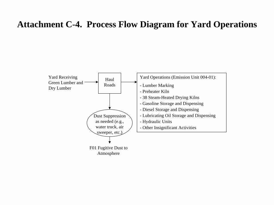
Attachment C-4. Process Flow Diagram for Yard Operations
Yard Operations (Emission Unit 004-01):
- Lumber Marking- Preheater Kiln- 38 Steam-Heated Drying Kilns- Gasoline Storage and Dispensing- Diesel Storage and Dispensing- Lubricating Oil Storage and Dispensing- Hydraulic Units- Other Insignificant Activities
Haul Roads
Yard Receiving Green Lumber and Dry Lumber
Dust Suppression as needed (e.g., water truck, air sweeper, etc.)
F01 Fugitive Dust to Atmosphere
Attachment D
Equipment Tables
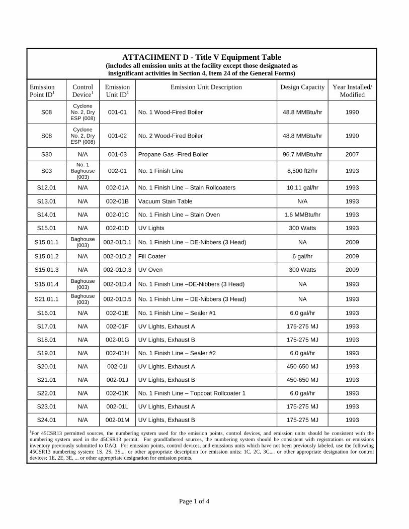
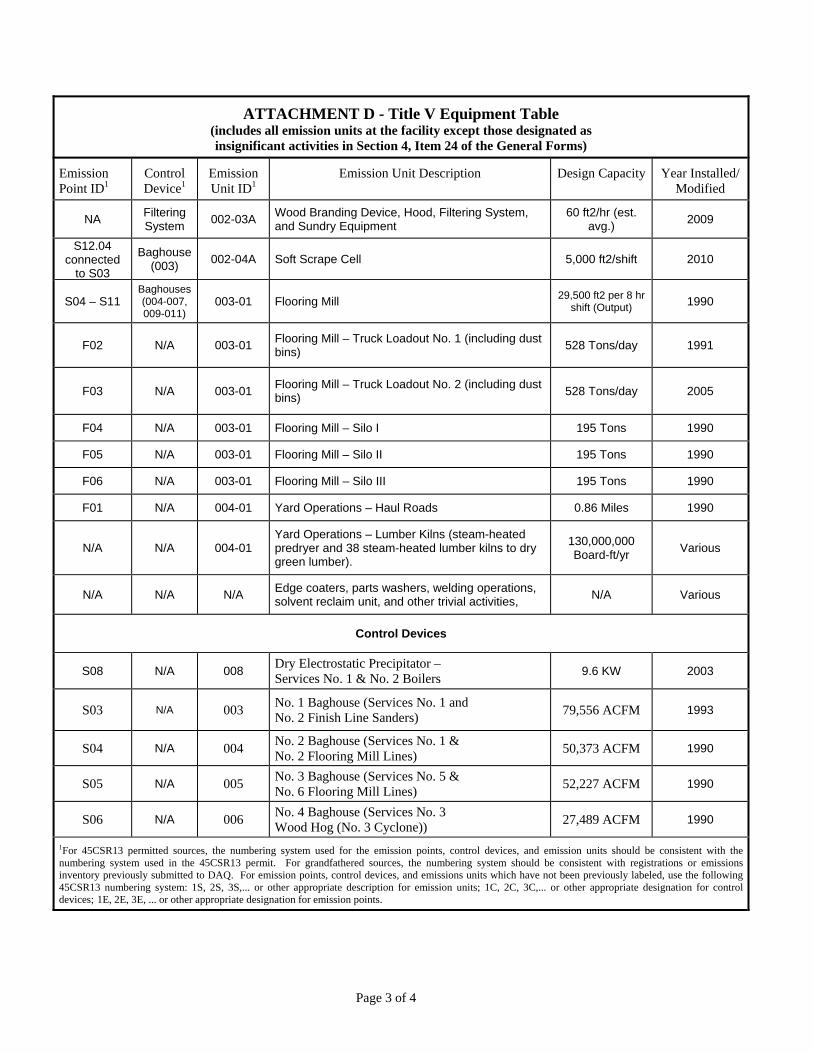
ATTACHMENT D - Title V Equipment Table (includes all emission units at the facility except those designated as insignificant activities in Section 4, Item 24 of the General Forms)
Emission Point ID1
Control Device1
Emission Unit ID1
Emission Unit Description Design Capacity Year Installed/ Modified
S08 Cyclone
No. 2, Dry ESP (008)
001-01 No. 1 Wood-Fired Boiler 48.8 MMBtu/hr 1990
S08 Cyclone
No. 2, Dry ESP (008)
001-02 No. 2 Wood-Fired Boiler 48.8 MMBtu/hr 1990
S30 N/A 001-03 Propane Gas -Fired Boiler 96.7 MMBtu/hr 2007
S03 No. 1
Baghouse (003)
002-01 No. 1 Finish Line 8,500 ft2/hr 1993
S12.01 N/A 002-01A No. 1 Finish Line – Stain Rollcoaters 10.11 gal/hr 1993
S13.01 N/A 002-01B Vacuum Stain Table N/A 1993
S14.01 N/A 002-01C No. 1 Finish Line – Stain Oven 1.6 MMBtu/hr 1993
S15.01 N/A 002-01D UV Lights 300 Watts 1993
S15.01.1 Baghouse
(003) 002-01D.1 No. 1 Finish Line – DE-Nibbers (3 Head) NA 2009
S15.01.2 N/A 002-01D.2 Fill Coater 6 gal/hr 2009
S15.01.3 N/A 002-01D.3 UV Oven 300 Watts 2009
S15.01.4 Baghouse (003) 002-01D.4 No. 1 Finish Line –DE-Nibbers (3 Head) NA 1993
S21.01.1 Baghouse (003) 002-01D.5 No. 1 Finish Line – DE-Nibbers (3 Head) NA 1993
S16.01 N/A 002-01E No. 1 Finish Line – Sealer #1 6.0 gal/hr 1993
S17.01 N/A 002-01F UV Lights, Exhaust A 175-275 MJ 1993
S18.01 N/A 002-01G UV Lights, Exhaust B 175-275 MJ 1993
S19.01 N/A 002-01H No. 1 Finish Line – Sealer #2 6.0 gal/hr 1993
S20.01 N/A 002-01I UV Lights, Exhaust A 450-650 MJ 1993
S21.01 N/A 002-01J UV Lights, Exhaust B 450-650 MJ 1993
S22.01 N/A 002-01K No. 1 Finish Line – Topcoat Rollcoater 1 6.0 gal/hr 1993
S23.01 N/A 002-01L UV Lights, Exhaust A 175-275 MJ 1993
S24.01 N/A 002-01M UV Lights, Exhaust B 175-275 MJ 1993
1For 45CSR13 permitted sources, the numbering system used for the emission points, control devices, and emission units should be consistent with the numbering system used in the 45CSR13 permit. For grandfathered sources, the numbering system should be consistent with registrations or emissions inventory previously submitted to DAQ. For emission points, control devices, and emissions units which have not been previously labeled, use the following 45CSR13 numbering system: 1S, 2S, 3S,... or other appropriate description for emission units; 1C, 2C, 3C,... or other appropriate designation for control devices; 1E, 2E, 3E, ... or other appropriate designation for emission points.
Page 1 of 4
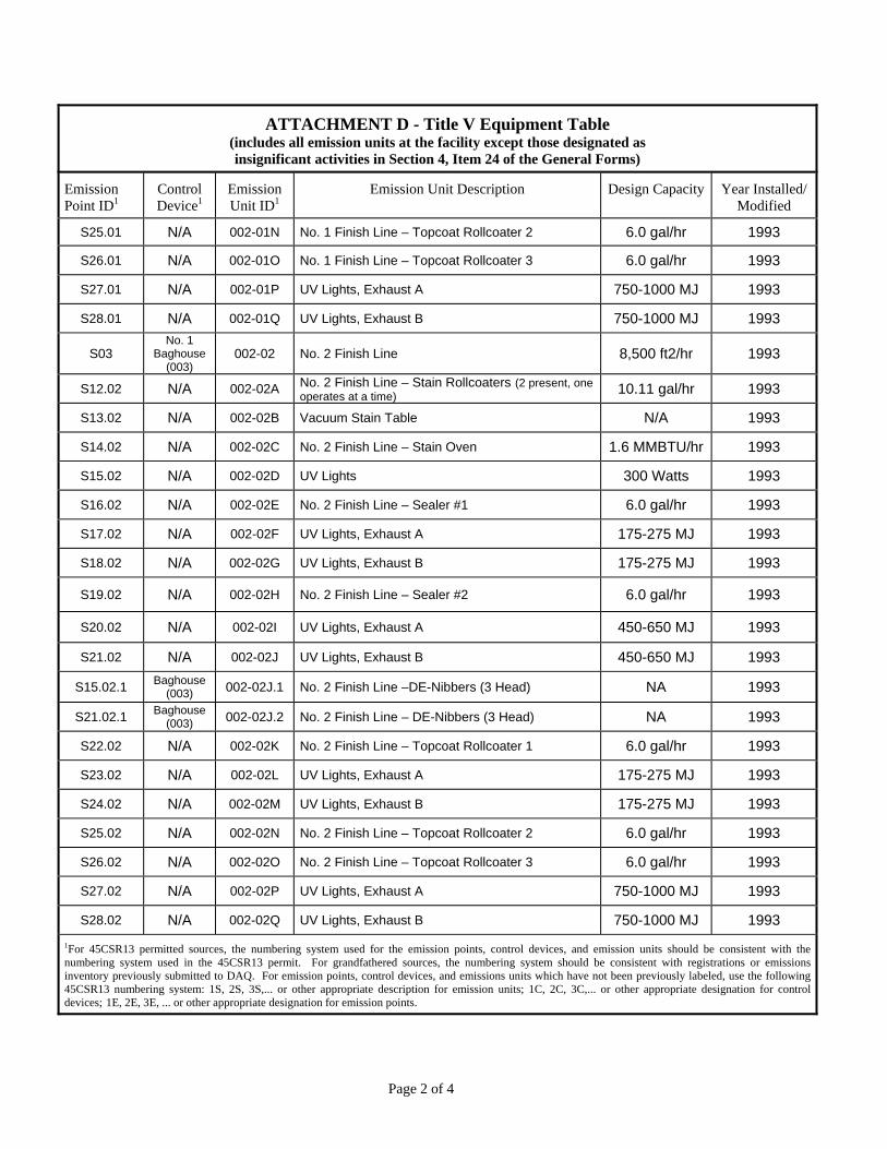
ATTACHMENT D - Title V Equipment Table (includes all emission units at the facility except those designated as insignificant activities in Section 4, Item 24 of the General Forms)
Emission Point ID1
Control Device1
Emission Unit ID1
Emission Unit Description Design Capacity Year Installed/ Modified
S25.01 N/A 002-01N No. 1 Finish Line – Topcoat Rollcoater 2 6.0 gal/hr 1993
S26.01 N/A 002-01O No. 1 Finish Line – Topcoat Rollcoater 3 6.0 gal/hr 1993
S27.01 N/A 002-01P UV Lights, Exhaust A 750-1000 MJ 1993
S28.01 N/A 002-01Q UV Lights, Exhaust B 750-1000 MJ 1993
S03 No. 1
Baghouse (003)
002-02 No. 2 Finish Line 8,500 ft2/hr 1993
S12.02 N/A 002-02A No. 2 Finish Line – Stain Rollcoaters (2 present, one operates at a time)
10.11 gal/hr 1993
S13.02 N/A 002-02B Vacuum Stain Table N/A 1993
S14.02 N/A 002-02C No. 2 Finish Line – Stain Oven 1.6 MMBTU/hr 1993
S15.02 N/A 002-02D UV Lights 300 Watts 1993
S16.02 N/A 002-02E No. 2 Finish Line – Sealer #1 6.0 gal/hr 1993
S17.02 N/A 002-02F UV Lights, Exhaust A 175-275 MJ 1993
S18.02 N/A 002-02G UV Lights, Exhaust B 175-275 MJ 1993
S19.02 N/A 002-02H No. 2 Finish Line – Sealer #2 6.0 gal/hr 1993
S20.02 N/A 002-02I UV Lights, Exhaust A 450-650 MJ 1993
S21.02 N/A 002-02J UV Lights, Exhaust B 450-650 MJ 1993
S15.02.1 Baghouse
(003) 002-02J.1 No. 2 Finish Line –DE-Nibbers (3 Head) NA 1993
S21.02.1 Baghouse
(003) 002-02J.2 No. 2 Finish Line – DE-Nibbers (3 Head) NA 1993
S22.02 N/A 002-02K No. 2 Finish Line – Topcoat Rollcoater 1 6.0 gal/hr 1993
S23.02 N/A 002-02L UV Lights, Exhaust A 175-275 MJ 1993
S24.02 N/A 002-02M UV Lights, Exhaust B 175-275 MJ 1993
S25.02 N/A 002-02N No. 2 Finish Line – Topcoat Rollcoater 2 6.0 gal/hr 1993
S26.02 N/A 002-02O No. 2 Finish Line – Topcoat Rollcoater 3 6.0 gal/hr 1993
S27.02 N/A 002-02P UV Lights, Exhaust A 750-1000 MJ 1993
S28.02 N/A 002-02Q UV Lights, Exhaust B 750-1000 MJ 1993
1For 45CSR13 permitted sources, the numbering system used for the emission points, control devices, and emission units should be consistent with the numbering system used in the 45CSR13 permit. For grandfathered sources, the numbering system should be consistent with registrations or emissions inventory previously submitted to DAQ. For emission points, control devices, and emissions units which have not been previously labeled, use the following 45CSR13 numbering system: 1S, 2S, 3S,... or other appropriate description for emission units; 1C, 2C, 3C,... or other appropriate designation for control devices; 1E, 2E, 3E, ... or other appropriate designation for emission points.
Page 2 of 4
ATTACHMENT D - Title V Equipment Table (includes all emission units at the facility except those designated as insignificant activities in Section 4, Item 24 of the General Forms)
Emission Point ID1
Control Device1
Emission Unit ID1
Emission Unit Description Design Capacity Year Installed/ Modified
NA Filtering System
002-03A Wood Branding Device, Hood, Filtering System, and Sundry Equipment
60 ft2/hr (est. avg.)
2009
S12.04 connected
to S03
Baghouse (003)
002-04A Soft Scrape Cell 5,000 ft2/shift 2010
S04 – S11 Baghouses (004-007, 009-011)
003-01 Flooring Mill 29,500 ft2 per 8 hr
shift (Output) 1990
F02 N/A 003-01 Flooring Mill – Truck Loadout No. 1 (including dust bins)
528 Tons/day 1991
F03 N/A 003-01 Flooring Mill – Truck Loadout No. 2 (including dust bins)
528 Tons/day 2005
F04 N/A 003-01 Flooring Mill – Silo I 195 Tons 1990
F05 N/A 003-01 Flooring Mill – Silo II 195 Tons 1990
F06 N/A 003-01 Flooring Mill – Silo III 195 Tons 1990
F01 N/A 004-01 Yard Operations – Haul Roads 0.86 Miles 1990
N/A N/A 004-01 Yard Operations – Lumber Kilns (steam-heated predryer and 38 steam-heated lumber kilns to dry green lumber).
130,000,000 Board-ft/yr
Various
N/A N/A N/A Edge coaters, parts washers, welding operations, solvent reclaim unit, and other trivial activities,
N/A Various
Control Devices
S08 N/A 008 Dry Electrostatic Precipitator – Services No. 1 & No. 2 Boilers
9.6 KW 2003
S03 N/A 003 No. 1 Baghouse (Services No. 1 and No. 2 Finish Line Sanders)
79,556 ACFM 1993
S04 N/A 004 No. 2 Baghouse (Services No. 1 & No. 2 Flooring Mill Lines)
50,373 ACFM 1990
S05 N/A 005 No. 3 Baghouse (Services No. 5 & No. 6 Flooring Mill Lines)
52,227 ACFM 1990
S06 N/A 006 No. 4 Baghouse (Services No. 3 Wood Hog (No. 3 Cyclone))
27,489 ACFM 1990
1For 45CSR13 permitted sources, the numbering system used for the emission points, control devices, and emission units should be consistent with the numbering system used in the 45CSR13 permit. For grandfathered sources, the numbering system should be consistent with registrations or emissions inventory previously submitted to DAQ. For emission points, control devices, and emissions units which have not been previously labeled, use the following 45CSR13 numbering system: 1S, 2S, 3S,... or other appropriate description for emission units; 1C, 2C, 3C,... or other appropriate designation for control devices; 1E, 2E, 3E, ... or other appropriate designation for emission points.
Page 3 of 4
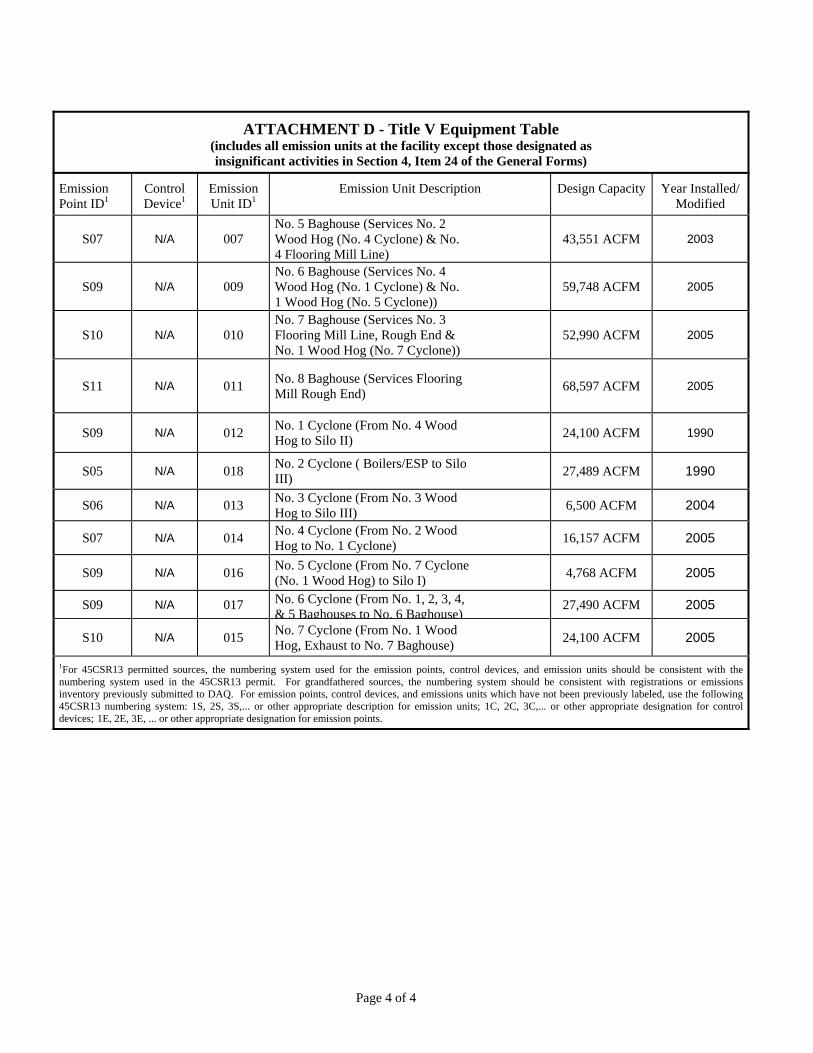
ATTACHMENT D - Title V Equipment Table (includes all emission units at the facility except those designated as insignificant activities in Section 4, Item 24 of the General Forms)
Emission Point ID1
Control Device1
Emission Unit ID1
Emission Unit Description Design Capacity Year Installed/ Modified
S07 N/A 007 No. 5 Baghouse (Services No. 2 Wood Hog (No. 4 Cyclone) & No. 4 Flooring Mill Line)
43,551 ACFM 2003
S09 N/A 009 No. 6 Baghouse (Services No. 4 Wood Hog (No. 1 Cyclone) & No. 1 Wood Hog (No. 5 Cyclone))
59,748 ACFM 2005
S10 N/A 010 No. 7 Baghouse (Services No. 3 Flooring Mill Line, Rough End & No. 1 Wood Hog (No. 7 Cyclone))
52,990 ACFM 2005
S11 N/A 011 No. 8 Baghouse (Services Flooring Mill Rough End)
68,597 ACFM 2005
S09 N/A 012 No. 1 Cyclone (From No. 4 Wood Hog to Silo II)
24,100 ACFM 1990
S05 N/A 018 No. 2 Cyclone ( Boilers/ESP to Silo III)
27,489 ACFM 1990
S06 N/A 013 No. 3 Cyclone (From No. 3 Wood Hog to Silo III)
6,500 ACFM 2004
S07 N/A 014 No. 4 Cyclone (From No. 2 Wood Hog to No. 1 Cyclone)
16,157 ACFM 2005
S09 N/A 016 No. 5 Cyclone (From No. 7 Cyclone (No. 1 Wood Hog) to Silo I)
4,768 ACFM 2005
S09 N/A 017 No. 6 Cyclone (From No. 1, 2, 3, 4, & 5 Baghouses to No. 6 Baghouse)
27,490 ACFM 2005
S10 N/A 015 No. 7 Cyclone (From No. 1 Wood Hog, Exhaust to No. 7 Baghouse)
24,100 ACFM 2005
1For 45CSR13 permitted sources, the numbering system used for the emission points, control devices, and emission units should be consistent with the numbering system used in the 45CSR13 permit. For grandfathered sources, the numbering system should be consistent with registrations or emissions inventory previously submitted to DAQ. For emission points, control devices, and emissions units which have not been previously labeled, use the following 45CSR13 numbering system: 1S, 2S, 3S,... or other appropriate description for emission units; 1C, 2C, 3C,... or other appropriate designation for control devices; 1E, 2E, 3E, ... or other appropriate designation for emission points.
Page 4 of 4
Attachment E
Emission Unit Forms
Page 1 of 20
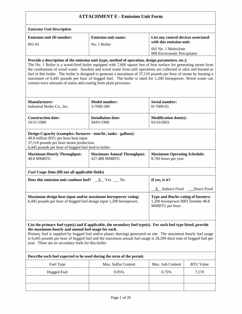
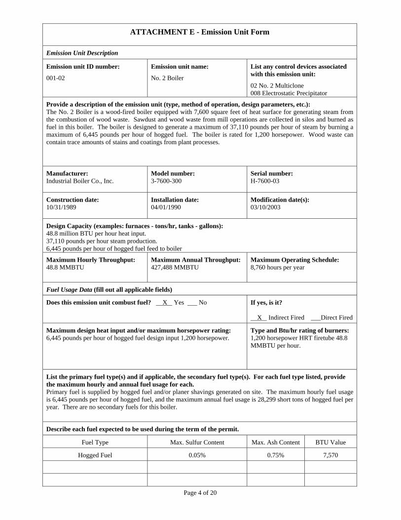
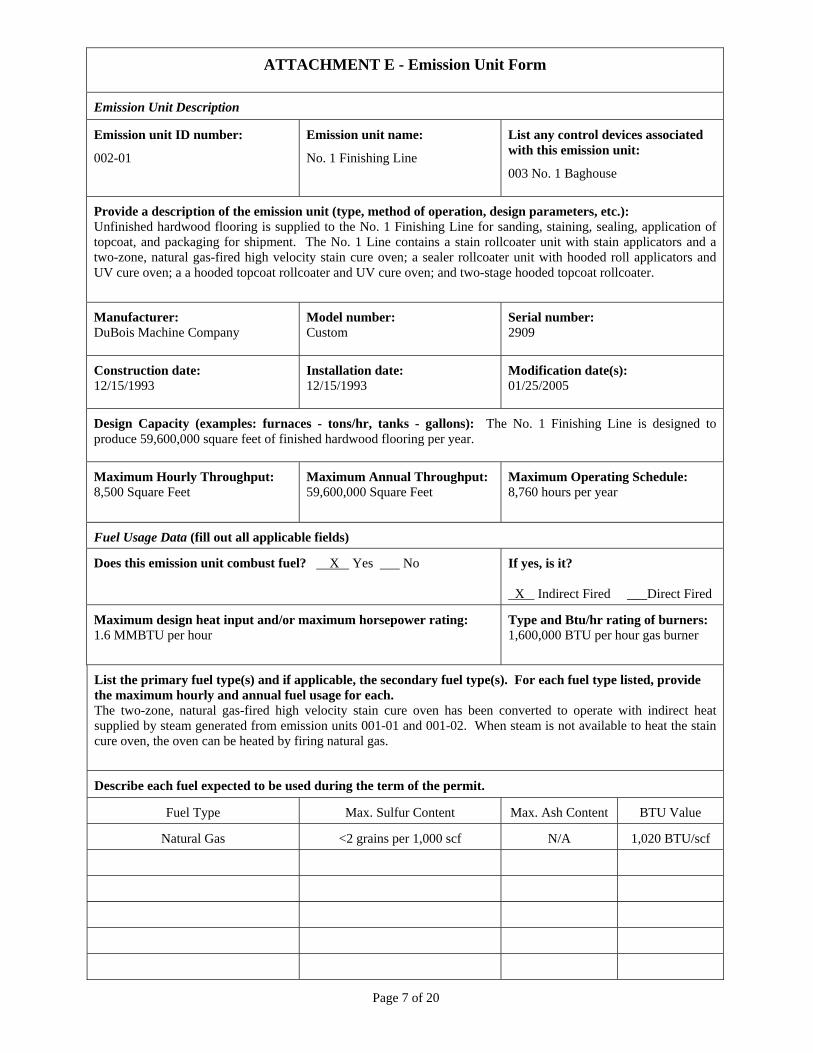
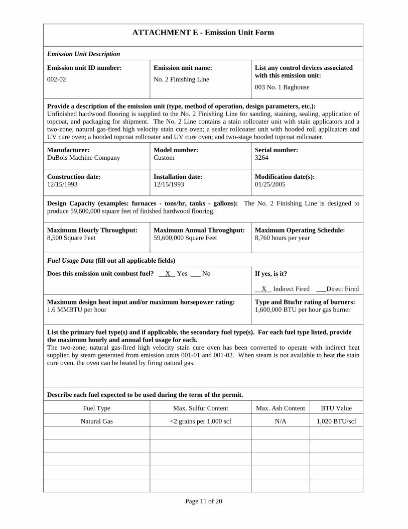
ATTACHMENT E - Emission Unit Form
Emission Unit Description
Emission unit ID number:
001-01
Emission unit name:
No. 1 Boiler
List any control devices associated with this emission unit:
001 No. 1 Multiclone 008 Electrostatic Precipitator
Provide a description of the emission unit (type, method of operation, design parameters, etc.): The No. 1 Boiler is a wood-fired boiler equipped with 7,600 square feet of heat surface for generating steam from the combustion of wood waste. Sawdust and wood waste from mill operations are collected in silos and burned as fuel in this boiler. The boiler is designed to generate a maximum of 37,110 pounds per hour of steam by burning a maximum of 6,445 pounds per hour of hogged fuel. The boiler is rated for 1,200 horsepower. Wood waste can contain trace amounts of stains and coating form plant processes.
Manufacturer: Industrial Boiler Co., Inc.
Model number: 3-7600-300
Serial number: H-7600-03
Construction date: 10/31/1989
Installation date: 04/01/1990
Modification date(s): 03/10/2003
Design Capacity (examples: furnaces - tons/hr, tanks - gallons): 48.8 million BTU per hour heat input. 37,110 pounds per hour steam production. 6,445 pounds per hour of hogged fuel feed to boiler.
Maximum Hourly Throughput: 48.8 MMBTU
Maximum Annual Throughput: 427,488 MMBTU
Maximum Operating Schedule: 8,760 hours per year
Fuel Usage Data (fill out all applicable fields)
Does this emission unit combust fuel? X Yes No If yes, is it? X Indirect Fired ___Direct Fired
Maximum design heat input and/or maximum horsepower rating: 6,445 pounds per hour of hogged fuel design input 1,200 horsepower.
Type and Btu/hr rating of burners: 1,200 horsepower HRT firetube 48.8 MMBTU per hour.
List the primary fuel type(s) and if applicable, the secondary fuel type(s). For each fuel type listed, provide the maximum hourly and annual fuel usage for each. Primary fuel is supplied by hogged fuel and/or planer shavings generated on site. The maximum hourly fuel usage is 6,445 pounds per hour of hogged fuel and the maximum annual fuel usage is 28,299 short tons of hogged fuel per year. There are no secondary fuels for this boiler.
Describe each fuel expected to be used during the term of the permit.
Fuel Type Max. Sulfur Content Max. Ash Content BTU Value
Hogged Fuel 0.05% 0.75% 7,570
Page 2 of 20
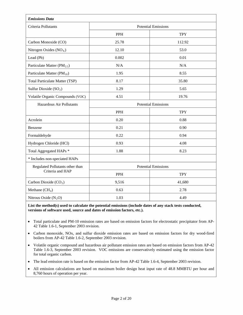
Emissions Data
Potential Emissions Criteria Pollutants
PPH TPY
Carbon Monoxide (CO) 25.78 112.92
Nitrogen Oxides (NOX) 12.10 53.0
Lead (Pb) 0.002 0.01
Particulate Matter (PM2.5) N/A N/A
Particulate Matter (PM10) 1.95 8.55
Total Particulate Matter (TSP) 8.17 35.80
Sulfur Dioxide (SO2) 1.29 5.65
Volatile Organic Compounds (VOC) 4.51 19.76
Potential Emissions Hazardous Air Pollutants
PPH TPY
Acrolein 0.20 0.88
Benzene 0.21 0.90
Formaldehyde 0.22 0.94
Hydrogen Chloride (HCl) 0.93 4.08
Total Aggregated HAPs * 1.88 8.23
* Includes non-speciated HAPs
Potential Emissions Regulated Pollutants other than Criteria and HAP
PPH TPY
Carbon Dioxide (CO2) 9,516 41,680
Methane (CH4) 0.63 2.78
Nitrous Oxide (N2O) 1.03 4.49
List the method(s) used to calculate the potential emissions (include dates of any stack tests conducted, versions of software used, source and dates of emission factors, etc.).
Total particulate and PM-10 emission rates are based on emission factors for electrostatic precipitator from AP-
42 Table 1.6-1, September 2003 revision.
Carbon monoxide, NOx, and sulfur dioxide emission rates are based on emission factors for dry wood-fired boilers from AP-42 Table 1.6-2, September 2003 revision.
Volatile organic compound and hazardous air pollutant emission rates are based on emission factors from AP-42 Table 1.6-3, September 2003 revision. VOC emissions are conservatively estimated using the emission factor for total organic carbon.
The lead emission rate is based on the emission factor from AP-42 Table 1.6-4, September 2003 revision.
All emission calculations are based on maximum boiler design heat input rate of 48.8 MMBTU per hour and 8,760 hours of operation per year.
Page 3 of 20
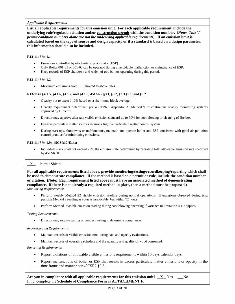
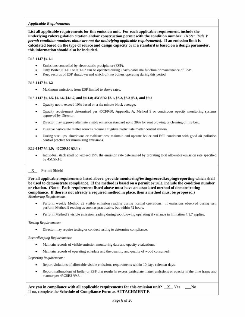
Applicable Requirements
List all applicable requirements for this emission unit. For each applicable requirement, include the underlying rule/regulation citation and/or construction permit with the condition number. (Note: Title V permit condition numbers alone are not the underlying applicable requirements). If an emission limit is calculated based on the type of source and design capacity or if a standard is based on a design parameter, this information should also be included.
R13-1147 §4.1.1
Emissions controlled by electrostatic precipitator (ESP). Only Boiler 001-01 or 001-02 can be operated during unavoidable malfunction or maintenance of ESP. Keep records of ESP shutdown and which of two boilers operating during this period.
R13-1147 §4.1.2
Maximum emissions from ESP limited to above rates. R13-1147 §4.1.5, §4.1.6, §4.1.7, and §4.1.8; 45CSR2 §3.1, §3.2, §3.3 §5.1, and §9.2
Opacity not to exceed 10% based on a six minute block average.
Opacity requirement determined per 40CFR60, Appendix A, Method 9 or continuous opacity monitoring systems approved by Director.
Director may approve alternate visible emission standard up to 30% for soot blowing or cleaning of fire box.
Fugitive particulate matter sources require a fugitive particulate matter control system.
During start-ups, shutdowns or malfunctions, maintain and operate boiler and ESP consistent with good air pollution control practice for minimizing emissions.
R13-1147 §4.1.9; 45CSR10 §3.4.a
Individual stack shall not exceed 25% the emission rate determined by prorating total allowable emission rate specified by 45CSR10.
X Permit Shield
For all applicable requirements listed above, provide monitoring/testing/recordkeeping/reporting which shall be used to demonstrate compliance. If the method is based on a permit or rule, include the condition number or citation. (Note: Each requirement listed above must have an associated method of demonstrating compliance. If there is not already a required method in place, then a method must be proposed.) Monitoring Requirements:
Perform weekly Method 22 visible emission reading during normal operations. If emissions observed during test, perform Method 9 reading as soon as practicable, but within 72 hours.
Perform Method 9 visible emission reading during soot blowing operating if variance in limitation 4.1.7 applies. Testing Requirements:
Director may require testing or conduct testing to determine compliance. Recordkeeping Requirements:
Maintain records of visible emission monitoring data and opacity evaluations.
Maintain records of operating schedule and the quantity and quality of wood consumed.
Reporting Requirements:
Report violations of allowable visible emissions requirements within 10 days calendar days.
Report malfunctions of boiler or ESP that results in excess particulate matter emissions or opacity in the time frame and manner per 45CSR2 §9.3.
Are you in compliance with all applicable requirements for this emission unit? X Yes ___No If no, complete the Schedule of Compliance Form as ATTACHMENT F.
Page 4 of 20
ATTACHMENT E - Emission Unit Form
Emission Unit Description
Emission unit ID number:
001-02
Emission unit name:
No. 2 Boiler
List any control devices associated with this emission unit:
02 No. 2 Multiclone 008 Electrostatic Precipitator
Provide a description of the emission unit (type, method of operation, design parameters, etc.): The No. 2 Boiler is a wood-fired boiler equipped with 7,600 square feet of heat surface for generating steam from the combustion of wood waste. Sawdust and wood waste from mill operations are collected in silos and burned as fuel in this boiler. The boiler is designed to generate a maximum of 37,110 pounds per hour of steam by burning a maximum of 6,445 pounds per hour of hogged fuel. The boiler is rated for 1,200 horsepower. Wood waste can contain trace amounts of stains and coatings from plant processes.
Manufacturer: Industrial Boiler Co., Inc.
Model number: 3-7600-300
Serial number: H-7600-03
Construction date: 10/31/1989
Installation date: 04/01/1990
Modification date(s): 03/10/2003
Design Capacity (examples: furnaces - tons/hr, tanks - gallons): 48.8 million BTU per hour heat input. 37,110 pounds per hour steam production. 6,445 pounds per hour of hogged fuel feed to boiler
Maximum Hourly Throughput: 48.8 MMBTU
Maximum Annual Throughput: 427,488 MMBTU
Maximum Operating Schedule: 8,760 hours per year
Fuel Usage Data (fill out all applicable fields)
Does this emission unit combust fuel? X Yes No If yes, is it? X Indirect Fired ___Direct Fired
Maximum design heat input and/or maximum horsepower rating: 6,445 pounds per hour of hogged fuel design input 1,200 horsepower.
Type and Btu/hr rating of burners: 1,200 horsepower HRT firetube 48.8 MMBTU per hour.
List the primary fuel type(s) and if applicable, the secondary fuel type(s). For each fuel type listed, provide the maximum hourly and annual fuel usage for each. Primary fuel is supplied by hogged fuel and/or planer shavings generated on site. The maximum hourly fuel usage is 6,445 pounds per hour of hogged fuel, and the maximum annual fuel usage is 28,299 short tons of hogged fuel per year. There are no secondary fuels for this boiler.
Describe each fuel expected to be used during the term of the permit.
Fuel Type Max. Sulfur Content Max. Ash Content BTU Value
Hogged Fuel 0.05% 0.75% 7,570
Page 5 of 20
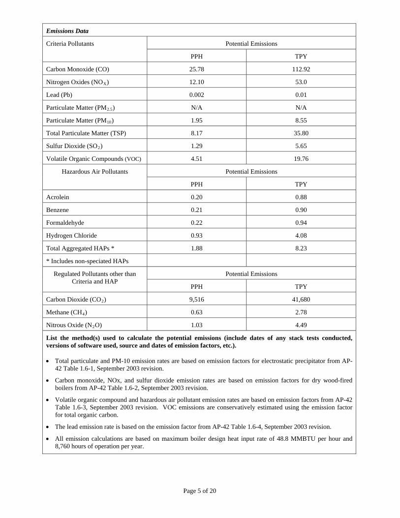
Emissions Data
Potential Emissions Criteria Pollutants
PPH TPY
Carbon Monoxide (CO) 25.78 112.92
Nitrogen Oxides (NOX) 12.10 53.0
Lead (Pb) 0.002 0.01
Particulate Matter (PM2.5) N/A N/A
Particulate Matter (PM10) 1.95 8.55
Total Particulate Matter (TSP) 8.17 35.80
Sulfur Dioxide (SO2) 1.29 5.65
Volatile Organic Compounds (VOC) 4.51 19.76
Potential Emissions Hazardous Air Pollutants
PPH TPY
Acrolein 0.20 0.88
Benzene 0.21 0.90
Formaldehyde 0.22 0.94
Hydrogen Chloride 0.93 4.08
Total Aggregated HAPs * 1.88 8.23
* Includes non-speciated HAPs
Potential Emissions Regulated Pollutants other than Criteria and HAP
PPH TPY
Carbon Dioxide (CO2) 9,516 41,680
Methane (CH4) 0.63 2.78
Nitrous Oxide (N2O) 1.03 4.49
List the method(s) used to calculate the potential emissions (include dates of any stack tests conducted, versions of software used, source and dates of emission factors, etc.). Total particulate and PM-10 emission rates are based on emission factors for electrostatic precipitator from AP-
42 Table 1.6-1, September 2003 revision.
Carbon monoxide, NOx, and sulfur dioxide emission rates are based on emission factors for dry wood-fired boilers from AP-42 Table 1.6-2, September 2003 revision.
Volatile organic compound and hazardous air pollutant emission rates are based on emission factors from AP-42 Table 1.6-3, September 2003 revision. VOC emissions are conservatively estimated using the emission factor for total organic carbon.
The lead emission rate is based on the emission factor from AP-42 Table 1.6-4, September 2003 revision.
All emission calculations are based on maximum boiler design heat input rate of 48.8 MMBTU per hour and 8,760 hours of operation per year.
Page 6 of 20
Applicable Requirements
List all applicable requirements for this emission unit. For each applicable requirement, include the underlying rule/regulation citation and/or construction permit with the condition number. (Note: Title V permit condition numbers alone are not the underlying applicable requirements). If an emission limit is calculated based on the type of source and design capacity or if a standard is based on a design parameter, this information should also be included. R13-1147 §4.1.1
Emissions controlled by electrostatic precipitator (ESP). Only Boiler 001-01 or 001-02 can be operated during unavoidable malfunction or maintenance of ESP. Keep records of ESP shutdown and which of two boilers operating during this period.
R13-1147 §4.1.2
Maximum emissions from ESP limited to above rates. R13-1147 §4.1.5, §4.1.6, §4.1.7, and §4.1.8; 45CSR2 §3.1, §3.2, §3.3 §5.1, and §9.2
Opacity not to exceed 10% based on a six minute block average.
Opacity requirement determined per 40CFR60, Appendix A, Method 9 or continuous opacity monitoring systems approved by Director.
Director may approve alternate visible emission standard up to 30% for soot blowing or cleaning of fire box.
Fugitive particulate matter sources require a fugitive particulate matter control system.
During start-ups, shutdowns or malfunctions, maintain and operate boiler and ESP consistent with good air pollution control practice for minimizing emissions.
R13-1147 §4.1.9; 45CSR10 §3.4.a
Individual stack shall not exceed 25% the emission rate determined by prorating total allowable emission rate specified by 45CSR10.
X Permit Shield
For all applicable requirements listed above, provide monitoring/testing/recordkeeping/reporting which shall be used to demonstrate compliance. If the method is based on a permit or rule, include the condition number or citation. (Note: Each requirement listed above must have an associated method of demonstrating compliance. If there is not already a required method in place, then a method must be proposed.) Monitoring Requirements:
Perform weekly Method 22 visible emission reading during normal operations. If emissions observed during test, perform Method 9 reading as soon as practicable, but within 72 hours.
Perform Method 9 visible emission reading during soot blowing operating if variance in limitation 4.1.7 applies. Testing Requirements:
Director may require testing or conduct testing to determine compliance. Recordkeeping Requirements:
Maintain records of visible emission monitoring data and opacity evaluations.
Maintain records of operating schedule and the quantity and quality of wood consumed.
Reporting Requirements:
Report violations of allowable visible emissions requirements within 10 days calendar days.
Report malfunctions of boiler or ESP that results in excess particulate matter emissions or opacity in the time frame and manner per 45CSR2 §9.3.
Are you in compliance with all applicable requirements for this emission unit? X Yes ___No If no, complete the Schedule of Compliance Form as ATTACHMENT F.
Page 7 of 20
ATTACHMENT E - Emission Unit Form
Emission Unit Description
Emission unit ID number:
002-01
Emission unit name:
No. 1 Finishing Line
List any control devices associated with this emission unit:
003 No. 1 Baghouse
Provide a description of the emission unit (type, method of operation, design parameters, etc.): Unfinished hardwood flooring is supplied to the No. 1 Finishing Line for sanding, staining, sealing, application of topcoat, and packaging for shipment. The No. 1 Line contains a stain rollcoater unit with stain applicators and a two-zone, natural gas-fired high velocity stain cure oven; a sealer rollcoater unit with hooded roll applicators and UV cure oven; a a hooded topcoat rollcoater and UV cure oven; and two-stage hooded topcoat rollcoater.
Manufacturer: DuBois Machine Company
Model number: Custom
Serial number: 2909
Construction date: 12/15/1993
Installation date: 12/15/1993
Modification date(s): 01/25/2005
Design Capacity (examples: furnaces - tons/hr, tanks - gallons): The No. 1 Finishing Line is designed to produce 59,600,000 square feet of finished hardwood flooring per year.
Maximum Hourly Throughput: 8,500 Square Feet
Maximum Annual Throughput: 59,600,000 Square Feet
Maximum Operating Schedule: 8,760 hours per year
Fuel Usage Data (fill out all applicable fields)
Does this emission unit combust fuel? X Yes No If yes, is it? X Indirect Fired ___Direct Fired
Maximum design heat input and/or maximum horsepower rating: 1.6 MMBTU per hour
Type and Btu/hr rating of burners: 1,600,000 BTU per hour gas burner
List the primary fuel type(s) and if applicable, the secondary fuel type(s). For each fuel type listed, provide the maximum hourly and annual fuel usage for each. The two-zone, natural gas-fired high velocity stain cure oven has been converted to operate with indirect heat supplied by steam generated from emission units 001-01 and 001-02. When steam is not available to heat the stain cure oven, the oven can be heated by firing natural gas.
Describe each fuel expected to be used during the term of the permit.
Fuel Type Max. Sulfur Content Max. Ash Content BTU Value
Natural Gas <2 grains per 1,000 scf N/A 1,020 BTU/scf
Page 8 of 20
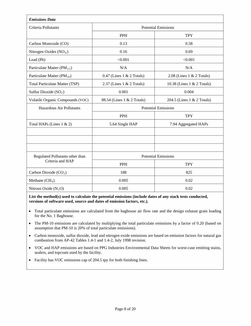
Emissions Data
Potential Emissions Criteria Pollutants
PPH TPY
Carbon Monoxide (CO) 0.13 0.58
Nitrogen Oxides (NOX) 0.16 0.69
Lead (Pb) <0.001 <0.001
Particulate Matter (PM2.5) N/A N/A
Particulate Matter (PM10) 0.47 (Lines 1 & 2 Totals) 2.08 (Lines 1 & 2 Totals)
Total Particulate Matter (TSP) 2.37 (Lines 1 & 2 Totals) 10.38 (Lines 1 & 2 Totals)
Sulfur Dioxide (SO2) 0.001 0.004
Volatile Organic Compounds (VOC) 88.54 (Lines 1 & 2 Totals) 204.5 (Lines 1 & 2 Totals)
Potential Emissions Hazardous Air Pollutants
PPH TPY
Total HAPs (Lines 1 & 2) 5.64 Single HAP 7.94 Aggregated HAPs
Potential Emissions Regulated Pollutants other than Criteria and HAP
PPH TPY
Carbon Dioxide (CO2) 188 825
Methane (CH4) 0.005 0.02
Nitrous Oxide (N2O) 0.005 0.02
List the method(s) used to calculate the potential emissions (include dates of any stack tests conducted, versions of software used, source and dates of emission factors, etc.). Total particulate emissions are calculated from the baghouse air flow rate and the design exhaust grain loading
for the No. 1 Baghouse.
The PM-10 emissions are calculated by multiplying the total particulate emissions by a factor of 0.20 (based on assumption that PM-10 is 20% of total particulate emissions).
Carbon monoxide, sulfur dioxide, lead and nitrogen oxide emissions are based on emission factors for natural gas combustion from AP-42 Tables 1.4-1 and 1.4-2, July 1998 revision.
VOC and HAP emissions are based on PPG Industries Environmental Data Sheets for worst-case emitting stains, sealers, and topcoats used by the facility.
Facility has VOC emissions cap of 204.5 tpy for both finishing lines.
Page 9 of 20
Applicable Requirements
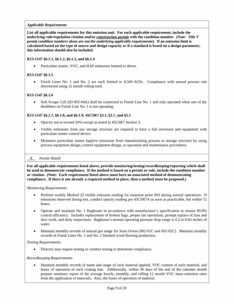
List all applicable requirements for this emission unit. For each applicable requirement, include the underlying rule/regulation citation and/or construction permit with the condition number. (Note: Title V permit condition numbers alone are not the underlying applicable requirements). If an emission limit is calculated based on the type of source and design capacity or if a standard is based on a design parameter, this information should also be included. R13-1147 §6.1.1, §6.1.2, §6.1.3, and §6.1.4
Particulate matter, VOC, and HAP emissions limited to above.
R13-1147 §6.1.5
Finish Lines No. 1 and No. 2 are each limited to 8,500 ft2/hr. Compliance with annual process rate determined using 12 month rolling total.
R13-1147 §6.1.6
Soft Scrape Cell (ID 002-04A) shall be connected to Finish Line No. 1 and only operated when one of the denibbers on Finish Line No. 1 is not operating.
R13-1147 §6.1.7, §6.1.8, and §6.1.9; 45CSR7 §3.1, §3.7, and §5.1
Opacity not to exceed 20% except as noted in 45CSR7 Section 3.
Visible emissions from any storage structure are required to have a full enclosure and equipment with particulate matter control device.
Minimize particulate matter fugitive emissions from manufacturing process or storage structure by using process equipment design, control equipment design, or operation and maintenance procedures.
X Permit Shield
For all applicable requirements listed above, provide monitoring/testing/recordkeeping/reporting which shall be used to demonstrate compliance. If the method is based on a permit or rule, include the condition number or citation. (Note: Each requirement listed above must have an associated method of demonstrating compliance. If there is not already a required method in place, then a method must be proposed.) Monitoring Requirements:
Perform weekly Method 22 visible emission reading for emission point S03 during normal operations. If emissions observed during test, conduct opacity reading per 45CSR7A as soon as practicable, but within 72 hours.
Operate and maintain No. 1 Baghouse in accordance with manufacturer’s specification to ensure 99.9% control efficiency. Includes replacement of broken bags, proper fan operations, prompt replace of fans and duct work, and daily inspections. Baghouse’s normal operating pressure drop range is 0.2 to 0.65 inches of water.
Maintain monthly records of natural gas usage for Stain Ovens (002-01C and 002-02C). Maintain monthly records of Finish Lines No. 1 and No. 2 finished wood flooring production.
Testing Requirements:
Director may require testing or conduct testing to determine compliance. Recordkeeping Requirements:
Maintain monthly records of name and usage of each material applied, VOC content of each material, and hours of operation of each coating line. Additionally, within 30 days of the end of the calendar month prepare summary report of the average hourly, monthly, and rolling 12 month VOC mass emission rates from the application of materials. Also, the hours of operation of material.

Page 10 of 20
Maintain monthly records of the name and material usage of each HAP containing material as applied, speciated HAP content of each material, and hours of operation of each coating line. Additionally, within 30 days of the end of the calendar month prepare summary report of the average hourly, monthly, and rolling 12 month aggregated and speciated HAP mass emission rates from the application of materials. Also, the hours of operation of material.
Maintain records of the amount of material processed on Finish Line No. 1 and No. 2 respectively.
Maintain records of all visible emission monitoring data.
Maintain records of baghouse monitoring data involved with proper operations, daily inspections, and pressure drop reading.
Maintain copies of MSDS, certified product data sheets, or manufacturer’s formulations for each surface coating, fill coating, clean-up solvent, and other related materials.
Reporting Requirements:
Report violations of allowable visible emissions requirements within 10 days calendar days.
Are you in compliance with all applicable requirements for this emission unit? X Yes ___No If no, complete the Schedule of Compliance Form as ATTACHMENT F.
Page 11 of 20
ATTACHMENT E - Emission Unit Form
Emission Unit Description
Emission unit ID number:
002-02
Emission unit name:
No. 2 Finishing Line
List any control devices associated with this emission unit:
003 No. 1 Baghouse
Provide a description of the emission unit (type, method of operation, design parameters, etc.): Unfinished hardwood flooring is supplied to the No. 2 Finishing Line for sanding, staining, sealing, application of topcoat, and packaging for shipment. The No. 2 Line contains a stain rollcoater unit with stain applicators and a two-zone, natural gas-fired high velocity stain cure oven; a sealer rollcoater unit with hooded roll applicators and UV cure oven; a hooded topcoat rollcoater and UV cure oven; and two-stage hooded topcoat rollcoater.
Manufacturer: DuBois Machine Company
Model number: Custom
Serial number: 3264
Construction date: 12/15/1993
Installation date: 12/15/1993
Modification date(s): 01/25/2005
Design Capacity (examples: furnaces - tons/hr, tanks - gallons): The No. 2 Finishing Line is designed to produce 59,600,000 square feet of finished hardwood flooring.
Maximum Hourly Throughput: 8,500 Square Feet
Maximum Annual Throughput: 59,600,000 Square Feet
Maximum Operating Schedule: 8,760 hours per year
Fuel Usage Data (fill out all applicable fields)
Does this emission unit combust fuel? X Yes No If yes, is it? X Indirect Fired ___Direct Fired
Maximum design heat input and/or maximum horsepower rating: 1.6 MMBTU per hour
Type and Btu/hr rating of burners: 1,600,000 BTU per hour gas burner
List the primary fuel type(s) and if applicable, the secondary fuel type(s). For each fuel type listed, provide the maximum hourly and annual fuel usage for each. The two-zone, natural gas-fired high velocity stain cure oven has been converted to operate with indirect heat supplied by steam generated from emission units 001-01 and 001-02. When steam is not available to heat the stain cure oven, the oven can be heated by firing natural gas.
Describe each fuel expected to be used during the term of the permit.
Fuel Type Max. Sulfur Content Max. Ash Content BTU Value
Natural Gas <2 grains per 1,000 scf N/A 1,020 BTU/scf
Page 12 of 20
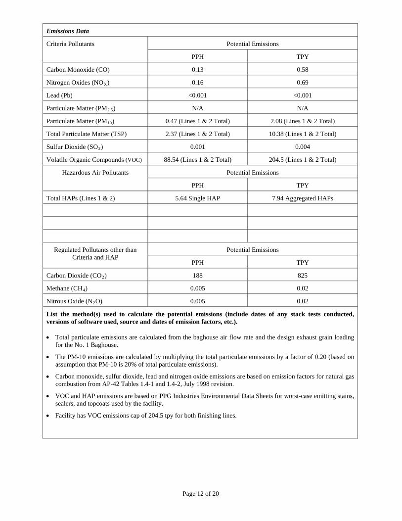
Emissions Data
Potential Emissions Criteria Pollutants
PPH TPY
Carbon Monoxide (CO) 0.13 0.58
Nitrogen Oxides (NOX) 0.16 0.69
Lead (Pb) <0.001 <0.001
Particulate Matter (PM2.5) N/A N/A
Particulate Matter (PM10) 0.47 (Lines 1 & 2 Total) 2.08 (Lines 1 & 2 Total)
Total Particulate Matter (TSP) 2.37 (Lines 1 & 2 Total) 10.38 (Lines 1 & 2 Total)
Sulfur Dioxide (SO2) 0.001 0.004
Volatile Organic Compounds (VOC) 88.54 (Lines 1 & 2 Total) 204.5 (Lines 1 & 2 Total)
Potential Emissions Hazardous Air Pollutants
PPH TPY
Total HAPs (Lines 1 & 2) 5.64 Single HAP 7.94 Aggregated HAPs
Potential Emissions Regulated Pollutants other than Criteria and HAP
PPH TPY
Carbon Dioxide (CO2) 188 825
Methane (CH4) 0.005 0.02
Nitrous Oxide (N2O) 0.005 0.02
List the method(s) used to calculate the potential emissions (include dates of any stack tests conducted, versions of software used, source and dates of emission factors, etc.). Total particulate emissions are calculated from the baghouse air flow rate and the design exhaust grain loading
for the No. 1 Baghouse.
The PM-10 emissions are calculated by multiplying the total particulate emissions by a factor of 0.20 (based on assumption that PM-10 is 20% of total particulate emissions).
Carbon monoxide, sulfur dioxide, lead and nitrogen oxide emissions are based on emission factors for natural gas combustion from AP-42 Tables 1.4-1 and 1.4-2, July 1998 revision.
VOC and HAP emissions are based on PPG Industries Environmental Data Sheets for worst-case emitting stains, sealers, and topcoats used by the facility.
Facility has VOC emissions cap of 204.5 tpy for both finishing lines.
Page 13 of 20
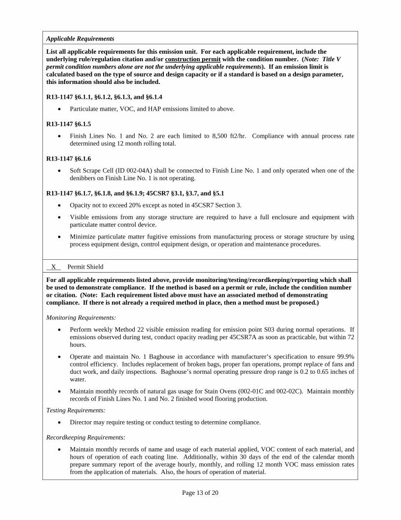
Applicable Requirements
List all applicable requirements for this emission unit. For each applicable requirement, include the underlying rule/regulation citation and/or construction permit with the condition number. (Note: Title V permit condition numbers alone are not the underlying applicable requirements). If an emission limit is calculated based on the type of source and design capacity or if a standard is based on a design parameter, this information should also be included. R13-1147 §6.1.1, §6.1.2, §6.1.3, and §6.1.4
Particulate matter, VOC, and HAP emissions limited to above.
R13-1147 §6.1.5
Finish Lines No. 1 and No. 2 are each limited to 8,500 ft2/hr. Compliance with annual process rate determined using 12 month rolling total.
R13-1147 §6.1.6
Soft Scrape Cell (ID 002-04A) shall be connected to Finish Line No. 1 and only operated when one of the denibbers on Finish Line No. 1 is not operating.
R13-1147 §6.1.7, §6.1.8, and §6.1.9; 45CSR7 §3.1, §3.7, and §5.1
Opacity not to exceed 20% except as noted in 45CSR7 Section 3.
Visible emissions from any storage structure are required to have a full enclosure and equipment with particulate matter control device.
Minimize particulate matter fugitive emissions from manufacturing process or storage structure by using process equipment design, control equipment design, or operation and maintenance procedures.
X Permit Shield
For all applicable requirements listed above, provide monitoring/testing/recordkeeping/reporting which shall be used to demonstrate compliance. If the method is based on a permit or rule, include the condition number or citation. (Note: Each requirement listed above must have an associated method of demonstrating compliance. If there is not already a required method in place, then a method must be proposed.) Monitoring Requirements:
Perform weekly Method 22 visible emission reading for emission point S03 during normal operations. If emissions observed during test, conduct opacity reading per 45CSR7A as soon as practicable, but within 72 hours.
Operate and maintain No. 1 Baghouse in accordance with manufacturer’s specification to ensure 99.9% control efficiency. Includes replacement of broken bags, proper fan operations, prompt replace of fans and duct work, and daily inspections. Baghouse’s normal operating pressure drop range is 0.2 to 0.65 inches of water.
Maintain monthly records of natural gas usage for Stain Ovens (002-01C and 002-02C). Maintain monthly records of Finish Lines No. 1 and No. 2 finished wood flooring production.
Testing Requirements:
Director may require testing or conduct testing to determine compliance. Recordkeeping Requirements:
Maintain monthly records of name and usage of each material applied, VOC content of each material, and hours of operation of each coating line. Additionally, within 30 days of the end of the calendar month prepare summary report of the average hourly, monthly, and rolling 12 month VOC mass emission rates from the application of materials. Also, the hours of operation of material.
Page 14 of 20
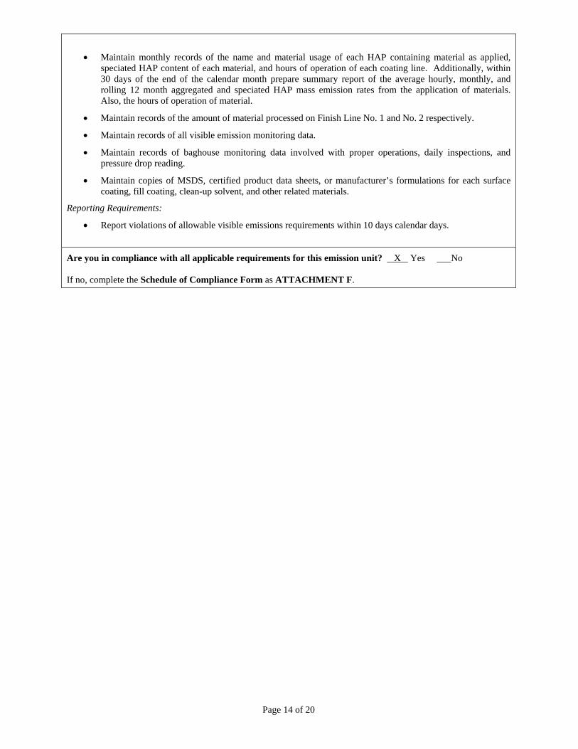
Maintain monthly records of the name and material usage of each HAP containing material as applied, speciated HAP content of each material, and hours of operation of each coating line. Additionally, within 30 days of the end of the calendar month prepare summary report of the average hourly, monthly, and rolling 12 month aggregated and speciated HAP mass emission rates from the application of materials. Also, the hours of operation of material.
Maintain records of the amount of material processed on Finish Line No. 1 and No. 2 respectively.
Maintain records of all visible emission monitoring data.
Maintain records of baghouse monitoring data involved with proper operations, daily inspections, and pressure drop reading.
Maintain copies of MSDS, certified product data sheets, or manufacturer’s formulations for each surface coating, fill coating, clean-up solvent, and other related materials.
Reporting Requirements:
Report violations of allowable visible emissions requirements within 10 days calendar days.
Are you in compliance with all applicable requirements for this emission unit? X Yes ___No If no, complete the Schedule of Compliance Form as ATTACHMENT F.
Page 15 of 20
ATTACHMENT E - Emission Unit Form
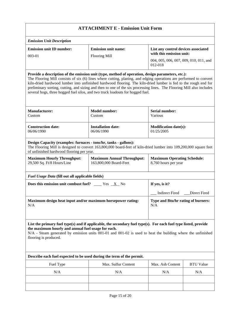
Emission Unit Description
Emission unit ID number:
003-01
Emission unit name:
Flooring Mill
List any control devices associated with this emission unit:
004, 005, 006, 007, 009, 010, 011, and 012-018
Provide a description of the emission unit (type, method of operation, design parameters, etc.): The Flooring Mill consists of six (6) lines where cutting, planing, and edging operations are performed to convert kiln-dried hardwood lumber into unfinished hardwood flooring. The kiln-dried lumber is fed to the rough end for preliminary sorting, cutting, and sizing and then to one of the six processing lines. The Flooring Mill also includes several hogs, three hogged fuel silos, and two truck loadouts for hogged fuel.
Manufacturer: Custom
Model number: Custom
Serial number: Various
Construction date: 06/06/1990
Installation date: 06/06/1990
Modification date(s): 01/25/2005
Design Capacity (examples: furnaces - tons/hr, tanks - gallons): The Flooring Mill is designed to convert 163,800,000 board-feet of kiln-dried lumber into 109,200,000 square feet of unfinished hardwood flooring per year.
Maximum Hourly Throughput: 29,500 Sq. Ft/8 Hours/Line
Maximum Annual Throughput: 163,800,000 Board-Feet
Maximum Operating Schedule: 8,760 hours per year
Fuel Usage Data (fill out all applicable fields)
Does this emission unit combust fuel? Yes X No If yes, is it? ___ Indirect Fired ___Direct Fired
Maximum design heat input and/or maximum horsepower rating: N/A
Type and Btu/hr rating of burners: N/A
List the primary fuel type(s) and if applicable, the secondary fuel type(s). For each fuel type listed, provide the maximum hourly and annual fuel usage for each. N/A - Steam generated by emission units 001-01 and 001-02 is used to heat the building where the unfinished flooring is produced.
Describe each fuel expected to be used during the term of the permit.
Fuel Type Max. Sulfur Content Max. Ash Content BTU Value
N/A N/A N/A N/A
Page 16 of 20
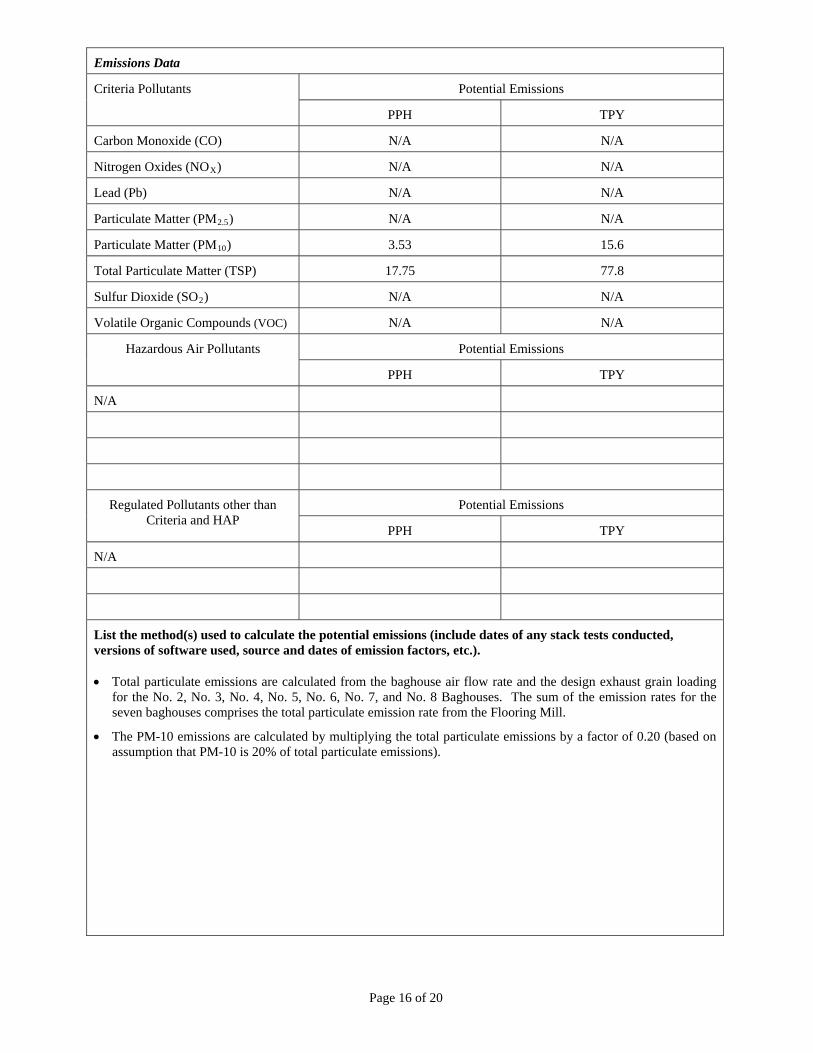
Emissions Data
Potential Emissions Criteria Pollutants
PPH TPY
Carbon Monoxide (CO) N/A N/A
Nitrogen Oxides (NOX) N/A N/A
Lead (Pb) N/A N/A
Particulate Matter (PM2.5) N/A N/A
Particulate Matter (PM10) 3.53 15.6
Total Particulate Matter (TSP) 17.75 77.8
Sulfur Dioxide (SO2) N/A N/A
Volatile Organic Compounds (VOC) N/A N/A
Potential Emissions Hazardous Air Pollutants
PPH TPY
N/A
Potential Emissions Regulated Pollutants other than Criteria and HAP
PPH TPY
N/A
List the method(s) used to calculate the potential emissions (include dates of any stack tests conducted, versions of software used, source and dates of emission factors, etc.). Total particulate emissions are calculated from the baghouse air flow rate and the design exhaust grain loading
for the No. 2, No. 3, No. 4, No. 5, No. 6, No. 7, and No. 8 Baghouses. The sum of the emission rates for the seven baghouses comprises the total particulate emission rate from the Flooring Mill.
The PM-10 emissions are calculated by multiplying the total particulate emissions by a factor of 0.20 (based on assumption that PM-10 is 20% of total particulate emissions).
Page 17 of 20
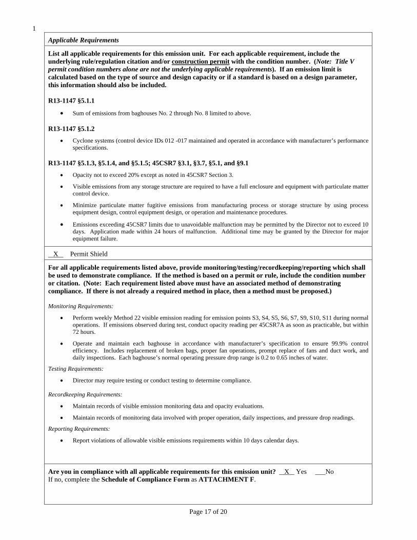
1
Applicable Requirements
List all applicable requirements for this emission unit. For each applicable requirement, include the underlying rule/regulation citation and/or construction permit with the condition number. (Note: Title V permit condition numbers alone are not the underlying applicable requirements). If an emission limit is calculated based on the type of source and design capacity or if a standard is based on a design parameter, this information should also be included. R13-1147 §5.1.1
Sum of emissions from baghouses No. 2 through No. 8 limited to above.
R13-1147 §5.1.2
Cyclone systems (control device IDs 012 -017 maintained and operated in accordance with manufacturer’s performance specifications.
R13-1147 §5.1.3, §5.1.4, and §5.1.5; 45CSR7 §3.1, §3.7, §5.1, and §9.1
Opacity not to exceed 20% except as noted in 45CSR7 Section 3.
Visible emissions from any storage structure are required to have a full enclosure and equipment with particulate matter control device.
Minimize particulate matter fugitive emissions from manufacturing process or storage structure by using process equipment design, control equipment design, or operation and maintenance procedures.
Emissions exceeding 45CSR7 limits due to unavoidable malfunction may be permitted by the Director not to exceed 10 days. Application made within 24 hours of malfunction. Additional time may be granted by the Director for major equipment failure.
X Permit Shield
For all applicable requirements listed above, provide monitoring/testing/recordkeeping/reporting which shall be used to demonstrate compliance. If the method is based on a permit or rule, include the condition number or citation. (Note: Each requirement listed above must have an associated method of demonstrating compliance. If there is not already a required method in place, then a method must be proposed.) Monitoring Requirements:
Perform weekly Method 22 visible emission reading for emission points S3, S4, S5, S6, S7, S9, S10, S11 during normal operations. If emissions observed during test, conduct opacity reading per 45CSR7A as soon as practicable, but within 72 hours.
Operate and maintain each baghouse in accordance with manufacturer’s specification to ensure 99.9% control efficiency. Includes replacement of broken bags, proper fan operations, prompt replace of fans and duct work, and daily inspections. Each baghouse’s normal operating pressure drop range is 0.2 to 0.65 inches of water.
Testing Requirements:
Director may require testing or conduct testing to determine compliance. Recordkeeping Requirements:
Maintain records of visible emission monitoring data and opacity evaluations.
Maintain records of monitoring data involved with proper operation, daily inspections, and pressure drop readings.
Reporting Requirements:
Report violations of allowable visible emissions requirements within 10 days calendar days.
Are you in compliance with all applicable requirements for this emission unit? X Yes ___No If no, complete the Schedule of Compliance Form as ATTACHMENT F.
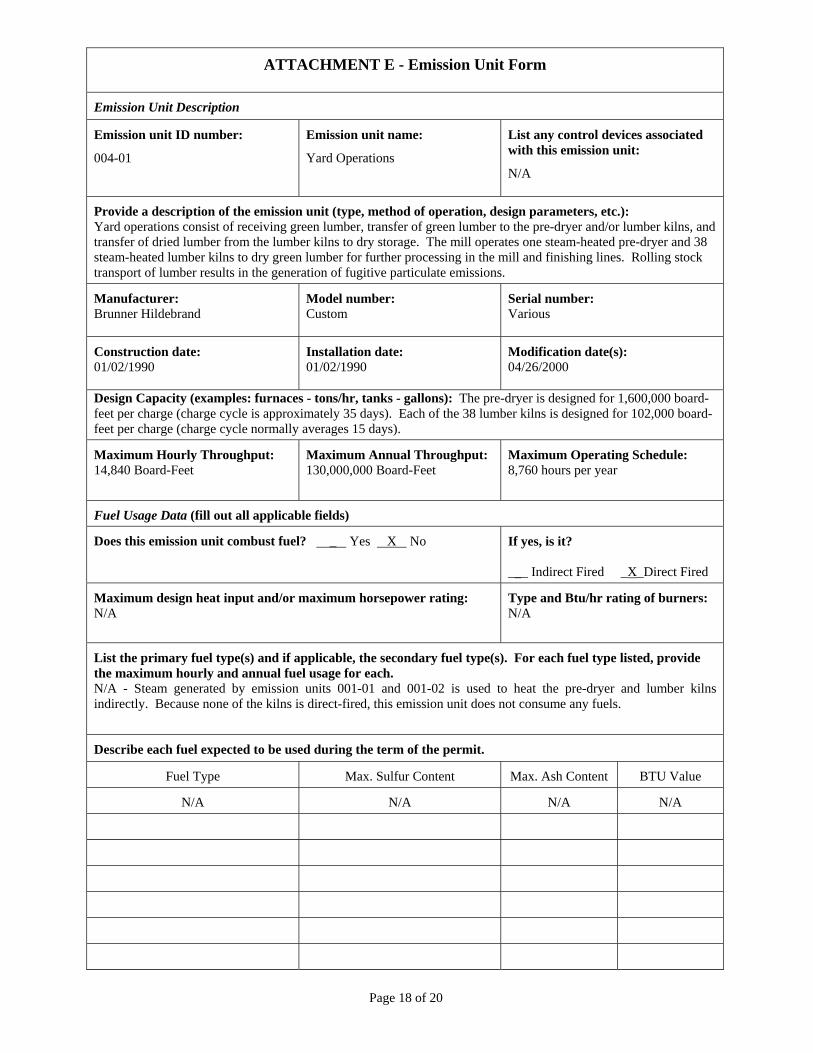
Page 18 of 20
ATTACHMENT E - Emission Unit Form
Emission Unit Description
Emission unit ID number:
004-01
Emission unit name:
Yard Operations
List any control devices associated with this emission unit:
N/A
Provide a description of the emission unit (type, method of operation, design parameters, etc.): Yard operations consist of receiving green lumber, transfer of green lumber to the pre-dryer and/or lumber kilns, and transfer of dried lumber from the lumber kilns to dry storage. The mill operates one steam-heated pre-dryer and 38 steam-heated lumber kilns to dry green lumber for further processing in the mill and finishing lines. Rolling stock transport of lumber results in the generation of fugitive particulate emissions.
Manufacturer: Brunner Hildebrand
Model number: Custom
Serial number: Various
Construction date: 01/02/1990
Installation date: 01/02/1990
Modification date(s): 04/26/2000
Design Capacity (examples: furnaces - tons/hr, tanks - gallons): The pre-dryer is designed for 1,600,000 board-feet per charge (charge cycle is approximately 35 days). Each of the 38 lumber kilns is designed for 102,000 board-feet per charge (charge cycle normally averages 15 days).
Maximum Hourly Throughput: 14,840 Board-Feet
Maximum Annual Throughput: 130,000,000 Board-Feet
Maximum Operating Schedule: 8,760 hours per year
Fuel Usage Data (fill out all applicable fields)
Does this emission unit combust fuel? _ Yes X No If yes, is it? ___ Indirect Fired _X_Direct Fired
Maximum design heat input and/or maximum horsepower rating: N/A
Type and Btu/hr rating of burners: N/A
List the primary fuel type(s) and if applicable, the secondary fuel type(s). For each fuel type listed, provide the maximum hourly and annual fuel usage for each. N/A - Steam generated by emission units 001-01 and 001-02 is used to heat the pre-dryer and lumber kilns indirectly. Because none of the kilns is direct-fired, this emission unit does not consume any fuels.
Describe each fuel expected to be used during the term of the permit.
Fuel Type Max. Sulfur Content Max. Ash Content BTU Value
N/A N/A N/A N/A
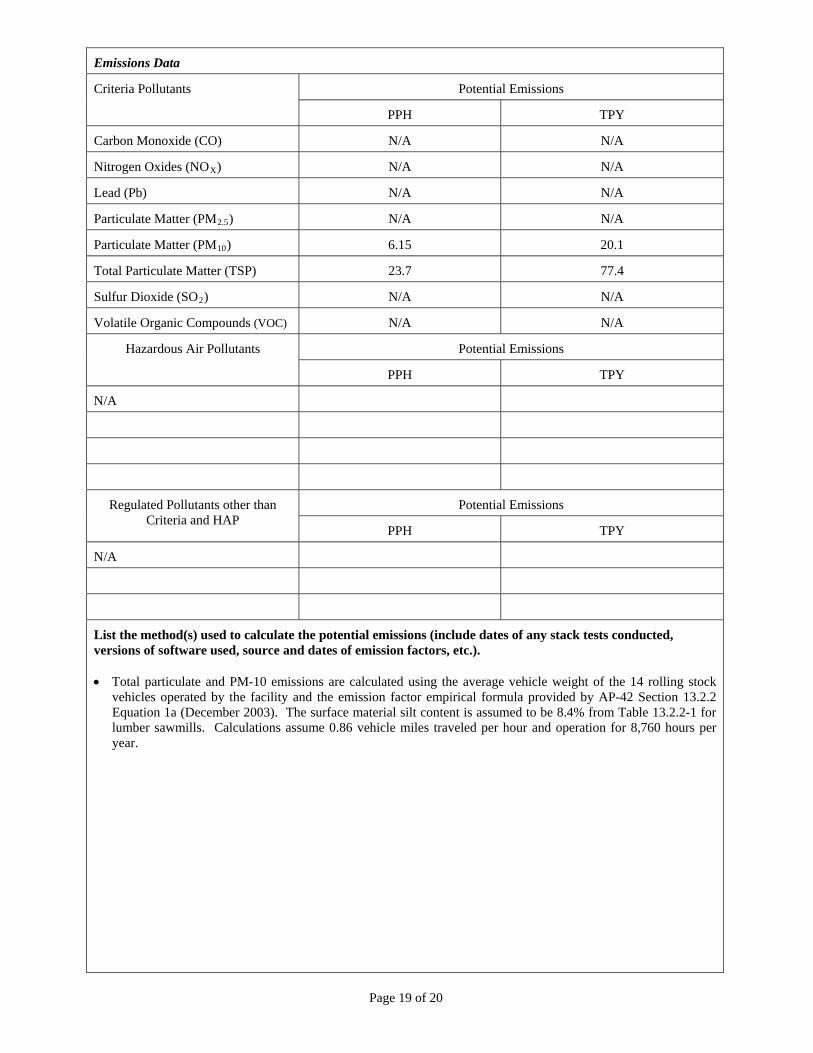
Page 19 of 20
Emissions Data
Potential Emissions Criteria Pollutants
PPH TPY
Carbon Monoxide (CO) N/A N/A
Nitrogen Oxides (NOX) N/A N/A
Lead (Pb) N/A N/A
Particulate Matter (PM2.5) N/A N/A
Particulate Matter (PM10) 6.15 20.1
Total Particulate Matter (TSP) 23.7 77.4
Sulfur Dioxide (SO2) N/A N/A
Volatile Organic Compounds (VOC) N/A N/A
Potential Emissions Hazardous Air Pollutants
PPH TPY
N/A
Potential Emissions Regulated Pollutants other than Criteria and HAP
PPH TPY
N/A
List the method(s) used to calculate the potential emissions (include dates of any stack tests conducted, versions of software used, source and dates of emission factors, etc.). Total particulate and PM-10 emissions are calculated using the average vehicle weight of the 14 rolling stock
vehicles operated by the facility and the emission factor empirical formula provided by AP-42 Section 13.2.2 Equation 1a (December 2003). The surface material silt content is assumed to be 8.4% from Table 13.2.2-1 for lumber sawmills. Calculations assume 0.86 vehicle miles traveled per hour and operation for 8,760 hours per year.
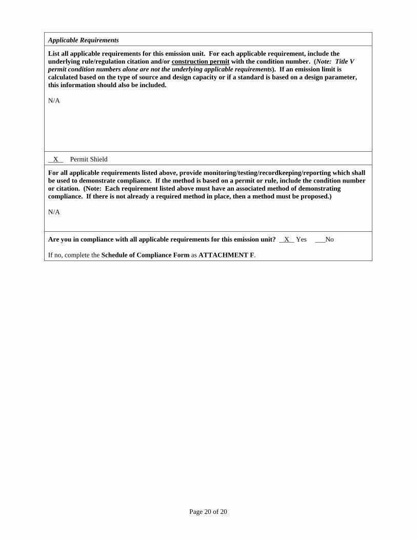
Page 20 of 20
Applicable Requirements
List all applicable requirements for this emission unit. For each applicable requirement, include the underlying rule/regulation citation and/or construction permit with the condition number. (Note: Title V permit condition numbers alone are not the underlying applicable requirements). If an emission limit is calculated based on the type of source and design capacity or if a standard is based on a design parameter, this information should also be included. N/A
X Permit Shield
For all applicable requirements listed above, provide monitoring/testing/recordkeeping/reporting which shall be used to demonstrate compliance. If the method is based on a permit or rule, include the condition number or citation. (Note: Each requirement listed above must have an associated method of demonstrating compliance. If there is not already a required method in place, then a method must be proposed.) N/A
Are you in compliance with all applicable requirements for this emission unit? X Yes ___No If no, complete the Schedule of Compliance Form as ATTACHMENT F.
Attachment F
Schedule of Compliance
Schedule of Compliance is Not Applicable
Schedule of Compliance Form (compliance_schedule.doc) Page 1 of 1
Revised – 8/18/04
Page _____ of _____
ATTACHMENT F - Schedule of Compliance Form
Complete this section if you indicated noncompliance with any of the applicable requirements identified in the permit application. For each emission unit which is not in compliance, identify the applicable requirement, the reason(s) for noncompliance, a description of how the source will achieve compliance, and a detailed schedule of compliance. If there is a consent order that applies to this requirement, attach a copy to this form.
1. Applicable Requirement
Unit(s):
Applicable Requirement:
2. Reason for Noncompliance:
3. How will Compliance be Achieved?
4. Consent Order Number (if applicable): 5. Schedule of Compliance. Provide a schedule of remedial measures, including an enforceable sequence of
actions with milestones, leading to compliance, including a date for final compliance.
Remedial Measure or Action Date to be Achieved
6. Submittal of Progress Reports.
Content of Progress Report:
Report starting date: MM/DD/YYYY Submittal frequency:
Attachment G
Air Pollution Control Device Forms
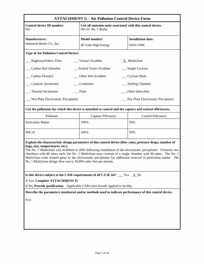
Page 1 of 18
ATTACHMENT G - Air Pollution Control Device Form
Control device ID number: 001
List all emission units associated with this control device. 001-01 No. 1 Boiler
Manufacturer: Industrial Boiler Co., Inc..
Model number:
86 Tube High Energy
Installation date:
04/01/1990
Type of Air Pollution Control Device: ___ Baghouse/Fabric Filter ___ Venturi Scrubber _X_ Multiclone ___ Carbon Bed Adsorber Packed Tower Scrubber ___ Single Cyclone ___ Carbon Drum(s) ___ Other Wet Scrubber ___ Cyclone Bank ___ Catalytic Incinerator ___ Condenser ___ Settling Chamber ___ Thermal Incinerator ___ Flare Other (describe) ___ Wet Plate Electrostatic Precipitator ___ Dry Plate Electrostatic Precipitator
List the pollutants for which this device is intended to control and the capture and control efficiencies.
Pollutant Capture Efficiency Control Efficiency
Particulate Matter 100% 50%
PM-10 100% 50%
Explain the characteristic design parameters of this control device (flow rates, pressure drops, number of bags, size, temperatures, etc.). The No. 1 Multiclone was modified in 2003 following installation of the electrostatic precipitator. Formerly two chambers with 86 tubes each, the No. 1 Multiclone now consists of a single chamber with 86 tubes. The No. 1 Multiclone vents treated gases to the electrostatic precipitator for additional removal of particulate matter. The No. 1 Multiclone design flow rate is 18,800 cubic feet per minute.
Is this device subject to the CAM requirements of 40 C.F.R. 64? ___ Yes X No
If Yes, Complete ATTACHMENT H
If No, Provide justification. Applicable CAM rules already applied to facility.
Describe the parameters monitored and/or methods used to indicate performance of this control device. N/A
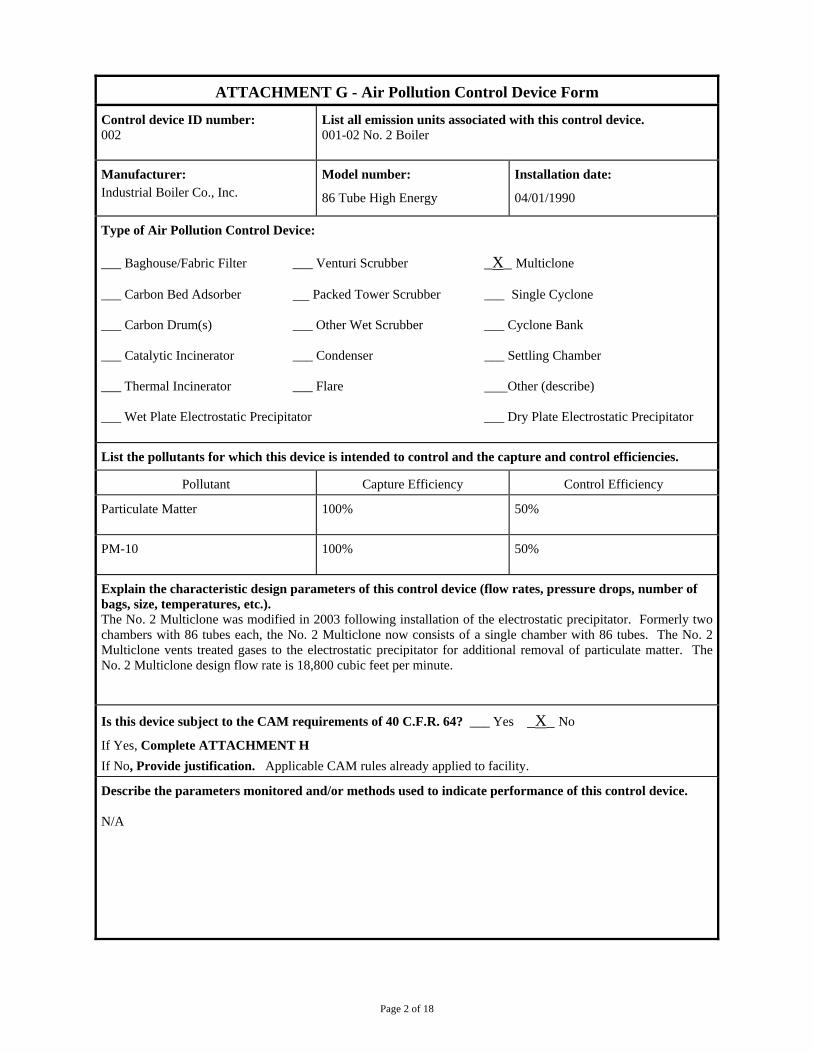
Page 2 of 18
ATTACHMENT G - Air Pollution Control Device Form
Control device ID number: 002
List all emission units associated with this control device. 001-02 No. 2 Boiler
Manufacturer: Industrial Boiler Co., Inc.
Model number:
86 Tube High Energy
Installation date:
04/01/1990
Type of Air Pollution Control Device: ___ Baghouse/Fabric Filter ___ Venturi Scrubber _X_ Multiclone ___ Carbon Bed Adsorber Packed Tower Scrubber ___ Single Cyclone ___ Carbon Drum(s) ___ Other Wet Scrubber ___ Cyclone Bank ___ Catalytic Incinerator ___ Condenser ___ Settling Chamber ___ Thermal Incinerator ___ Flare Other (describe) ___ Wet Plate Electrostatic Precipitator ___ Dry Plate Electrostatic Precipitator
List the pollutants for which this device is intended to control and the capture and control efficiencies.
Pollutant Capture Efficiency Control Efficiency
Particulate Matter 100% 50%
PM-10 100% 50%
Explain the characteristic design parameters of this control device (flow rates, pressure drops, number of bags, size, temperatures, etc.). The No. 2 Multiclone was modified in 2003 following installation of the electrostatic precipitator. Formerly two chambers with 86 tubes each, the No. 2 Multiclone now consists of a single chamber with 86 tubes. The No. 2 Multiclone vents treated gases to the electrostatic precipitator for additional removal of particulate matter. The No. 2 Multiclone design flow rate is 18,800 cubic feet per minute.
Is this device subject to the CAM requirements of 40 C.F.R. 64? ___ Yes _X_ No
If Yes, Complete ATTACHMENT H
If No, Provide justification. Applicable CAM rules already applied to facility.
Describe the parameters monitored and/or methods used to indicate performance of this control device. N/A
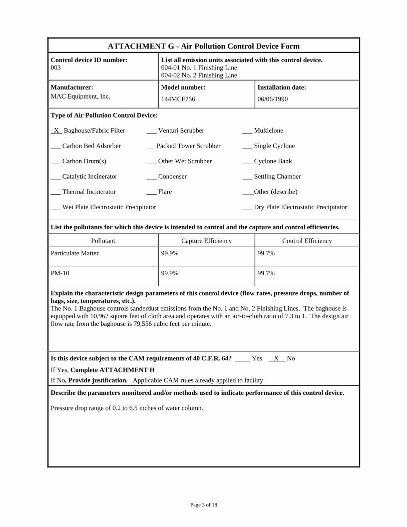
Page 3 of 18
ATTACHMENT G - Air Pollution Control Device Form
Control device ID number: 003
List all emission units associated with this control device. 004-01 No. 1 Finishing Line 004-02 No. 2 Finishing Line
Manufacturer: MAC Equipment, Inc.
Model number:
144MCF756
Installation date:
06/06/1990
Type of Air Pollution Control Device: X Baghouse/Fabric Filter ___ Venturi Scrubber ___ Multiclone ___ Carbon Bed Adsorber Packed Tower Scrubber ___ Single Cyclone ___ Carbon Drum(s) ___ Other Wet Scrubber ___ Cyclone Bank ___ Catalytic Incinerator ___ Condenser ___ Settling Chamber ___ Thermal Incinerator ___ Flare Other (describe) ___ Wet Plate Electrostatic Precipitator ___ Dry Plate Electrostatic Precipitator
List the pollutants for which this device is intended to control and the capture and control efficiencies.
Pollutant Capture Efficiency Control Efficiency
Particulate Matter 99.9% 99.7%
PM-10 99.9% 99.7%
Explain the characteristic design parameters of this control device (flow rates, pressure drops, number of bags, size, temperatures, etc.). The No. 1 Baghouse controls sanderdust emissions from the No. 1 and No. 2 Finishing Lines. The baghouse is equipped with 10,962 square feet of cloth area and operates with an air-to-cloth ratio of 7.3 to 1. The design air flow rate from the baghouse is 79,556 cubic feet per minute.
Is this device subject to the CAM requirements of 40 C.F.R. 64? Yes X No
If Yes, Complete ATTACHMENT H
If No, Provide justification. Applicable CAM rules already applied to facility.
Describe the parameters monitored and/or methods used to indicate performance of this control device. Pressure drop range of 0.2 to 6.5 inches of water column.
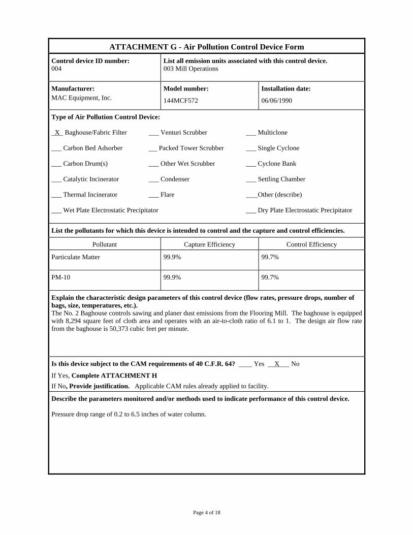
Page 4 of 18
ATTACHMENT G - Air Pollution Control Device Form
Control device ID number: 004
List all emission units associated with this control device. 003 Mill Operations
Manufacturer: MAC Equipment, Inc.
Model number:
144MCF572
Installation date:
06/06/1990
Type of Air Pollution Control Device: _X_ Baghouse/Fabric Filter ___ Venturi Scrubber ___ Multiclone ___ Carbon Bed Adsorber Packed Tower Scrubber ___ Single Cyclone ___ Carbon Drum(s) ___ Other Wet Scrubber ___ Cyclone Bank ___ Catalytic Incinerator ___ Condenser ___ Settling Chamber ___ Thermal Incinerator ___ Flare Other (describe) ___ Wet Plate Electrostatic Precipitator ___ Dry Plate Electrostatic Precipitator
List the pollutants for which this device is intended to control and the capture and control efficiencies.
Pollutant Capture Efficiency Control Efficiency
Particulate Matter 99.9% 99.7%
PM-10 99.9% 99.7%
Explain the characteristic design parameters of this control device (flow rates, pressure drops, number of bags, size, temperatures, etc.). The No. 2 Baghouse controls sawing and planer dust emissions from the Flooring Mill. The baghouse is equipped with 8,294 square feet of cloth area and operates with an air-to-cloth ratio of 6.1 to 1. The design air flow rate from the baghouse is 50,373 cubic feet per minute.
Is this device subject to the CAM requirements of 40 C.F.R. 64? Yes X No
If Yes, Complete ATTACHMENT H
If No, Provide justification. Applicable CAM rules already applied to facility.
Describe the parameters monitored and/or methods used to indicate performance of this control device. Pressure drop range of 0.2 to 6.5 inches of water column.
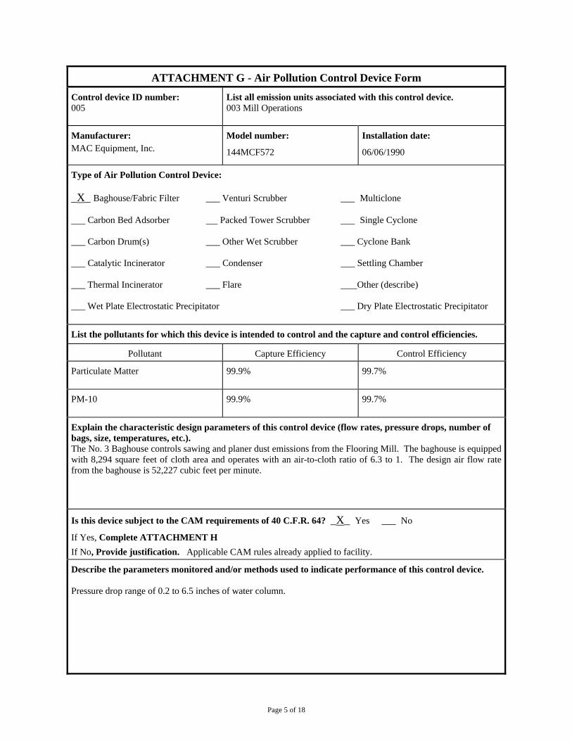
Page 5 of 18
ATTACHMENT G - Air Pollution Control Device Form
Control device ID number: 005
List all emission units associated with this control device. 003 Mill Operations
Manufacturer: MAC Equipment, Inc.
Model number:
144MCF572
Installation date:
06/06/1990
Type of Air Pollution Control Device: _X_ Baghouse/Fabric Filter ___ Venturi Scrubber ___ Multiclone ___ Carbon Bed Adsorber Packed Tower Scrubber ___ Single Cyclone ___ Carbon Drum(s) ___ Other Wet Scrubber ___ Cyclone Bank ___ Catalytic Incinerator ___ Condenser ___ Settling Chamber ___ Thermal Incinerator ___ Flare Other (describe) ___ Wet Plate Electrostatic Precipitator ___ Dry Plate Electrostatic Precipitator
List the pollutants for which this device is intended to control and the capture and control efficiencies.
Pollutant Capture Efficiency Control Efficiency
Particulate Matter 99.9% 99.7%
PM-10 99.9% 99.7%
Explain the characteristic design parameters of this control device (flow rates, pressure drops, number of bags, size, temperatures, etc.). The No. 3 Baghouse controls sawing and planer dust emissions from the Flooring Mill. The baghouse is equipped with 8,294 square feet of cloth area and operates with an air-to-cloth ratio of 6.3 to 1. The design air flow rate from the baghouse is 52,227 cubic feet per minute.
Is this device subject to the CAM requirements of 40 C.F.R. 64? _X_ Yes ___ No
If Yes, Complete ATTACHMENT H
If No, Provide justification. Applicable CAM rules already applied to facility.
Describe the parameters monitored and/or methods used to indicate performance of this control device. Pressure drop range of 0.2 to 6.5 inches of water column.

Page 6 of 18
.
ATTACHMENT G - Air Pollution Control Device Form
Control device ID number: 006
List all emission units associated with this control device. 003 Mill Operations
Manufacturer: MAC Equipment, Inc.
Model number:
144MCF255
Installation date:
06/06/1990
Type of Air Pollution Control Device: _X_ Baghouse/Fabric Filter ___ Venturi Scrubber ___ Multiclone ___ Carbon Bed Adsorber Packed Tower Scrubber ___ Single Cyclone ___ Carbon Drum(s) ___ Other Wet Scrubber ___ Cyclone Bank ___ Catalytic Incinerator ___ Condenser ___ Settling Chamber ___ Thermal Incinerator ___ Flare Other (describe) ___ Wet Plate Electrostatic Precipitator ___ Dry Plate Electrostatic Precipitator
List the pollutants for which this device is intended to control and the capture and control efficiencies.
Pollutant Capture Efficiency Control Efficiency
Particulate Matter 99.9% 99.7%
PM-10 99.9% 99.7%
Explain the characteristic design parameters of this control device (flow rates, pressure drops, number of bags, size, temperatures, etc.). The No. 4 Baghouse controls emissions from the No. 2 Cyclone (Red Wood Hog). The baghouse is equipped with 3,698 square feet of cloth area and operates with an air-to-cloth ratio of 7.4 to 1. The design air flow rate from the baghouse is 27,489 cubic feet per minute.
Is this device subject to the CAM requirements of 40 C.F.R. 64? _X_ Yes ___ No
If Yes, Complete ATTACHMENT H
If No, Provide justification. Applicable CAM rules already applied to facility.
Describe the parameters monitored and/or methods used to indicate performance of this control device. Pressure drop range of 0.2 to 6.5 inches of water column.
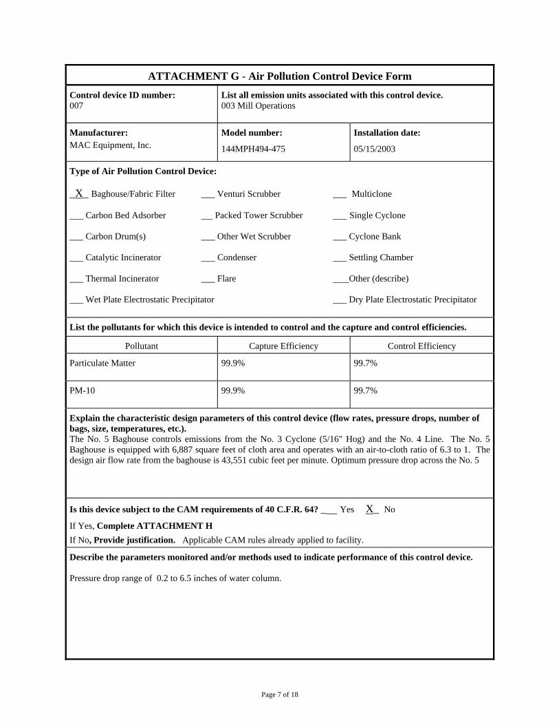
Page 7 of 18
ATTACHMENT G - Air Pollution Control Device Form
Control device ID number: 007
List all emission units associated with this control device. 003 Mill Operations
Manufacturer: MAC Equipment, Inc.
Model number:
144MPH494-475
Installation date:
05/15/2003
Type of Air Pollution Control Device: _X_ Baghouse/Fabric Filter ___ Venturi Scrubber ___ Multiclone ___ Carbon Bed Adsorber Packed Tower Scrubber ___ Single Cyclone ___ Carbon Drum(s) ___ Other Wet Scrubber ___ Cyclone Bank ___ Catalytic Incinerator ___ Condenser ___ Settling Chamber ___ Thermal Incinerator ___ Flare Other (describe) ___ Wet Plate Electrostatic Precipitator ___ Dry Plate Electrostatic Precipitator
List the pollutants for which this device is intended to control and the capture and control efficiencies.
Pollutant Capture Efficiency Control Efficiency
Particulate Matter 99.9% 99.7%
PM-10 99.9% 99.7%
Explain the characteristic design parameters of this control device (flow rates, pressure drops, number of bags, size, temperatures, etc.). The No. 5 Baghouse controls emissions from the No. 3 Cyclone (5/16" Hog) and the No. 4 Line. The No. 5 Baghouse is equipped with 6,887 square feet of cloth area and operates with an air-to-cloth ratio of 6.3 to 1. The design air flow rate from the baghouse is 43,551 cubic feet per minute. Optimum pressure drop across the No. 5
Is this device subject to the CAM requirements of 40 C.F.R. 64? _ Yes X_ No
If Yes, Complete ATTACHMENT H
If No, Provide justification. Applicable CAM rules already applied to facility.
Describe the parameters monitored and/or methods used to indicate performance of this control device. Pressure drop range of 0.2 to 6.5 inches of water column.
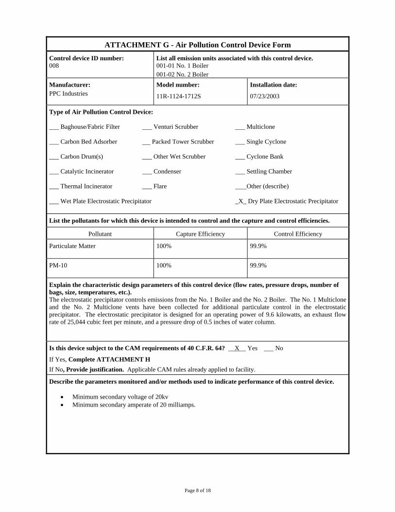
Page 8 of 18
ATTACHMENT G - Air Pollution Control Device Form
Control device ID number: 008
List all emission units associated with this control device. 001-01 No. 1 Boiler 001-02 No. 2 Boiler
Manufacturer: PPC Industries
Model number:
11R-1124-1712S
Installation date:
07/23/2003
Type of Air Pollution Control Device: Baghouse/Fabric Filter ___ Venturi Scrubber ___ Multiclone ___ Carbon Bed Adsorber Packed Tower Scrubber ___ Single Cyclone ___ Carbon Drum(s) ___ Other Wet Scrubber ___ Cyclone Bank ___ Catalytic Incinerator ___ Condenser ___ Settling Chamber ___ Thermal Incinerator ___ Flare Other (describe) ___ Wet Plate Electrostatic Precipitator _X_ Dry Plate Electrostatic Precipitator
List the pollutants for which this device is intended to control and the capture and control efficiencies.
Pollutant Capture Efficiency Control Efficiency
Particulate Matter 100% 99.9%
PM-10 100% 99.9%
Explain the characteristic design parameters of this control device (flow rates, pressure drops, number of bags, size, temperatures, etc.). The electrostatic precipitator controls emissions from the No. 1 Boiler and the No. 2 Boiler. The No. 1 Multiclone and the No. 2 Multiclone vents have been collected for additional particulate control in the electrostatic precipitator. The electrostatic precipitator is designed for an operating power of 9.6 kilowatts, an exhaust flow rate of 25,044 cubic feet per minute, and a pressure drop of 0.5 inches of water column.
Is this device subject to the CAM requirements of 40 C.F.R. 64? X Yes No
If Yes, Complete ATTACHMENT H
If No, Provide justification. Applicable CAM rules already applied to facility.
Describe the parameters monitored and/or methods used to indicate performance of this control device.
Minimum secondary voltage of 20kv Minimum secondary amperate of 20 milliamps.

Page 9 of 18
ATTACHMENT G - Air Pollution Control Device Form
Control device ID number: 009
List all emission units associated with this control device. 003 Mill Operations
Manufacturer: Ligna-Con, LLC
Model number:
16.5-700-12 Super Can
Installation date:
05/01/2005
Type of Air Pollution Control Device: _X_ Baghouse/Fabric Filter ___ Venturi Scrubber ___ Multiclone ___ Carbon Bed Adsorber Packed Tower Scrubber ___ Single Cyclone ___ Carbon Drum(s) ___ Other Wet Scrubber ___ Cyclone Bank ___ Catalytic Incinerator ___ Condenser ___ Settling Chamber ___ Thermal Incinerator ___ Flare Other (describe) ___ Wet Plate Electrostatic Precipitator ___ Dry Plate Electrostatic Precipitator
List the pollutants for which this device is intended to control and the capture and control efficiencies.
Pollutant Capture Efficiency Control Efficiency
Particulate Matter 99.9% 99.7%
PM-10 99.9% 99.7%
Explain the characteristic design parameters of this control device (flow rates, pressure drops, number of bags, size, temperatures, etc.). The No. 6 Baghouse controls emissions from the No. 1, No. 5, and No. 6 Cyclones. The No. 6 Baghouse is equipped with 10,150 square feet of cloth area and operates with an air-to-cloth ratio of 5.9 to 1. The design air flow rate from the baghouse is 59,748 cubic feet per minute. Optimum pressure drop across the No. 6 Baghouse is 0.75 to 5.0 inches of water column.
Is this device subject to the CAM requirements of 40 C.F.R. 64? _ Yes X_ No
If Yes, Complete ATTACHMENT H
If No, Provide justification. Applicable CAM rules already applied to facility.
Describe the parameters monitored and/or methods used to indicate performance of this control device. Pressure drop range of 0.2 to 6.5 inches of water column.

Page 10 of 18
ATTACHMENT G - Air Pollution Control Device Form
Control device ID number: 010
List all emission units associated with this control device. 003 Mill Operations
Manufacturer: Ligna-Con, LLC
Model number:
14.5-500-12
Installation date:
05/01/2005
Type of Air Pollution Control Device: _X_ Baghouse/Fabric Filter ___ Venturi Scrubber ___ Multiclone ___ Carbon Bed Adsorber Packed Tower Scrubber ___ Single Cyclone ___ Carbon Drum(s) ___ Other Wet Scrubber ___ Cyclone Bank ___ Catalytic Incinerator ___ Condenser ___ Settling Chamber ___ Thermal Incinerator ___ Flare Other (describe) ___ Wet Plate Electrostatic Precipitator ___ Dry Plate Electrostatic Precipitator
List the pollutants for which this device is intended to control and the capture and control efficiencies.
Pollutant Capture Efficiency Control Efficiency
Particulate Matter 99.9% 99.9%
PM-10 99.9% 99.9%
Explain the characteristic design parameters of this control device (flow rates, pressure drops, number of bags, size, temperatures, etc.). The No. 7 Baghouse controls emissions from the No. 3 Line, the No. 4 Cyclone, and the Rough End. The No. 7 Baghouse is equipped with 7,250 square feet of cloth area and operates with an air-to-cloth ratio of 6.9 to 1. The design air flow rate from the baghouse is 52,990 cubic feet per minute.
Is this device subject to the CAM requirements of 40 C.F.R. 64? _ Yes X No
If Yes, Complete ATTACHMENT H
If No, Provide justification. Applicable CAM rules already applied to facility.
Describe the parameters monitored and/or methods used to indicate performance of this control device. Pressure drop range of 0.2 to 6.5 inches of water column.
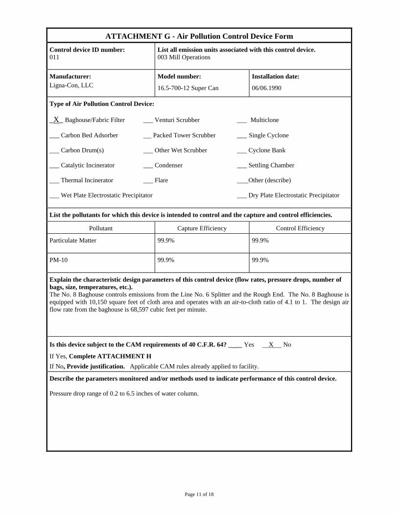
Page 11 of 18
ATTACHMENT G - Air Pollution Control Device Form
Control device ID number: 011
List all emission units associated with this control device. 003 Mill Operations
Manufacturer: Ligna-Con, LLC
Model number:
16.5-700-12 Super Can
Installation date:
06/06.1990
Type of Air Pollution Control Device: _X_ Baghouse/Fabric Filter ___ Venturi Scrubber ___ Multiclone ___ Carbon Bed Adsorber Packed Tower Scrubber ___ Single Cyclone ___ Carbon Drum(s) ___ Other Wet Scrubber ___ Cyclone Bank ___ Catalytic Incinerator ___ Condenser ___ Settling Chamber ___ Thermal Incinerator ___ Flare Other (describe) ___ Wet Plate Electrostatic Precipitator ___ Dry Plate Electrostatic Precipitator
List the pollutants for which this device is intended to control and the capture and control efficiencies.
Pollutant Capture Efficiency Control Efficiency
Particulate Matter 99.9% 99.9%
PM-10 99.9% 99.9%
Explain the characteristic design parameters of this control device (flow rates, pressure drops, number of bags, size, temperatures, etc.). The No. 8 Baghouse controls emissions from the Line No. 6 Splitter and the Rough End. The No. 8 Baghouse is equipped with 10,150 square feet of cloth area and operates with an air-to-cloth ratio of 4.1 to 1. The design air flow rate from the baghouse is 68,597 cubic feet per minute.
Is this device subject to the CAM requirements of 40 C.F.R. 64? _ _ Yes X No
If Yes, Complete ATTACHMENT H
If No, Provide justification. Applicable CAM rules already applied to facility.
Describe the parameters monitored and/or methods used to indicate performance of this control device. Pressure drop range of 0.2 to 6.5 inches of water column.
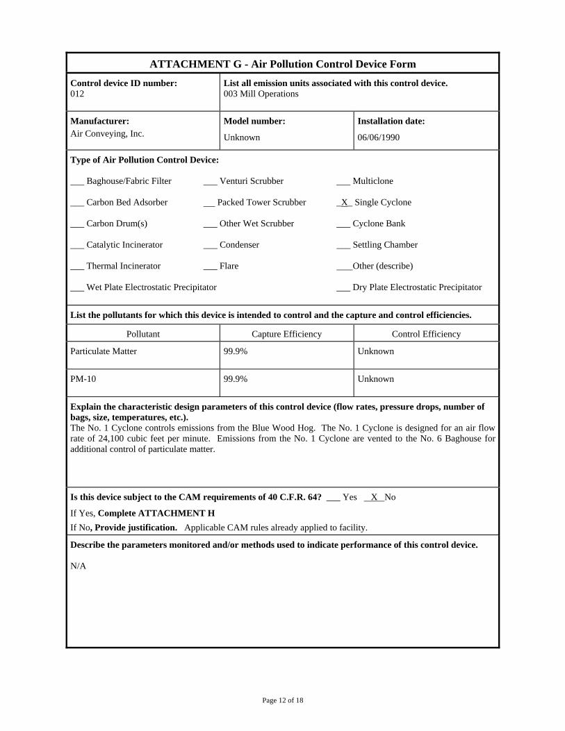
Page 12 of 18
ATTACHMENT G - Air Pollution Control Device Form
Control device ID number: 012
List all emission units associated with this control device. 003 Mill Operations
Manufacturer: Air Conveying, Inc.
Model number:
Unknown
Installation date:
06/06/1990
Type of Air Pollution Control Device: _ Baghouse/Fabric Filter ___ Venturi Scrubber ___ Multiclone ___ Carbon Bed Adsorber Packed Tower Scrubber _X_ Single Cyclone ___ Carbon Drum(s) ___ Other Wet Scrubber ___ Cyclone Bank ___ Catalytic Incinerator ___ Condenser ___ Settling Chamber ___ Thermal Incinerator ___ Flare Other (describe) ___ Wet Plate Electrostatic Precipitator ___ Dry Plate Electrostatic Precipitator
List the pollutants for which this device is intended to control and the capture and control efficiencies.
Pollutant Capture Efficiency Control Efficiency
Particulate Matter 99.9% Unknown
PM-10 99.9% Unknown
Explain the characteristic design parameters of this control device (flow rates, pressure drops, number of bags, size, temperatures, etc.). The No. 1 Cyclone controls emissions from the Blue Wood Hog. The No. 1 Cyclone is designed for an air flow rate of 24,100 cubic feet per minute. Emissions from the No. 1 Cyclone are vented to the No. 6 Baghouse for additional control of particulate matter.
Is this device subject to the CAM requirements of 40 C.F.R. 64? ___ Yes X No
If Yes, Complete ATTACHMENT H
If No, Provide justification. Applicable CAM rules already applied to facility.
Describe the parameters monitored and/or methods used to indicate performance of this control device. N/A
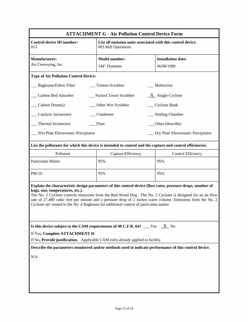
Page 13 of 18
ATTACHMENT G - Air Pollution Control Device Form
Control device ID number: 013
List all emission units associated with this control device. 003 Mill Operations
Manufacturer: Air Conveying, Inc.
Model number:
144" Diameter
Installation date:
06/06/1990
Type of Air Pollution Control Device: ___ Baghouse/Fabric Filter ___ Venturi Scrubber ___ Multiclone ___ Carbon Bed Adsorber Packed Tower Scrubber _X_ Single Cyclone ___ Carbon Drum(s) ___ Other Wet Scrubber ___ Cyclone Bank ___ Catalytic Incinerator ___ Condenser ___ Settling Chamber ___ Thermal Incinerator ___ Flare Other (describe) ___ Wet Plate Electrostatic Precipitator ___ Dry Plate Electrostatic Precipitator
List the pollutants for which this device is intended to control and the capture and control efficiencies.
Pollutant Capture Efficiency Control Efficiency
Particulate Matter 95% 95%
PM-10 95% 95%
Explain the characteristic design parameters of this control device (flow rates, pressure drops, number of bags, size, temperatures, etc.). The No. 2 Cyclone controls emissions from the Red Wood Hog. The No. 2 Cyclone is designed for an air flow rate of 27,489 cubic feet per minute and a pressure drop of 2 inches water column. Emissions from the No. 2 Cyclone are vented to the No. 4 Baghouse for additional control of particulate matter.
Is this device subject to the CAM requirements of 40 C.F.R. 64? ___ Yes _X_ No
If Yes, Complete ATTACHMENT H
If No, Provide justification. Applicable CAM rules already applied to facility.
Describe the parameters monitored and/or methods used to indicate performance of this control device. N/A
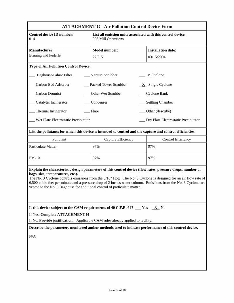
Page 14 of 18
ATTACHMENT G - Air Pollution Control Device Form
Control device ID number: 014
List all emission units associated with this control device. 003 Mill Operations
Manufacturer: Bruning and Federle
Model number:
22C15
Installation date:
03/15/2004
Type of Air Pollution Control Device: ___ Baghouse/Fabric Filter ___ Venturi Scrubber ___ Multiclone ___ Carbon Bed Adsorber Packed Tower Scrubber _X_ Single Cyclone ___ Carbon Drum(s) ___ Other Wet Scrubber ___ Cyclone Bank ___ Catalytic Incinerator ___ Condenser ___ Settling Chamber ___ Thermal Incinerator ___ Flare Other (describe) ___ Wet Plate Electrostatic Precipitator ___ Dry Plate Electrostatic Precipitator
List the pollutants for which this device is intended to control and the capture and control efficiencies.
Pollutant Capture Efficiency Control Efficiency
Particulate Matter 97% 97%
PM-10 97% 97%
Explain the characteristic design parameters of this control device (flow rates, pressure drops, number of bags, size, temperatures, etc.). The No. 3 Cyclone controls emissions from the 5/16" Hog. The No. 3 Cyclone is designed for an air flow rate of 6,500 cubic feet per minute and a pressure drop of 2 inches water column. Emissions from the No. 3 Cyclone are vented to the No. 5 Baghouse for additional control of particulate matter.
Is this device subject to the CAM requirements of 40 C.F.R. 64? ___ Yes _X_ No
If Yes, Complete ATTACHMENT H
If No, Provide justification. Applicable CAM rules already applied to facility.
Describe the parameters monitored and/or methods used to indicate performance of this control device. N/A
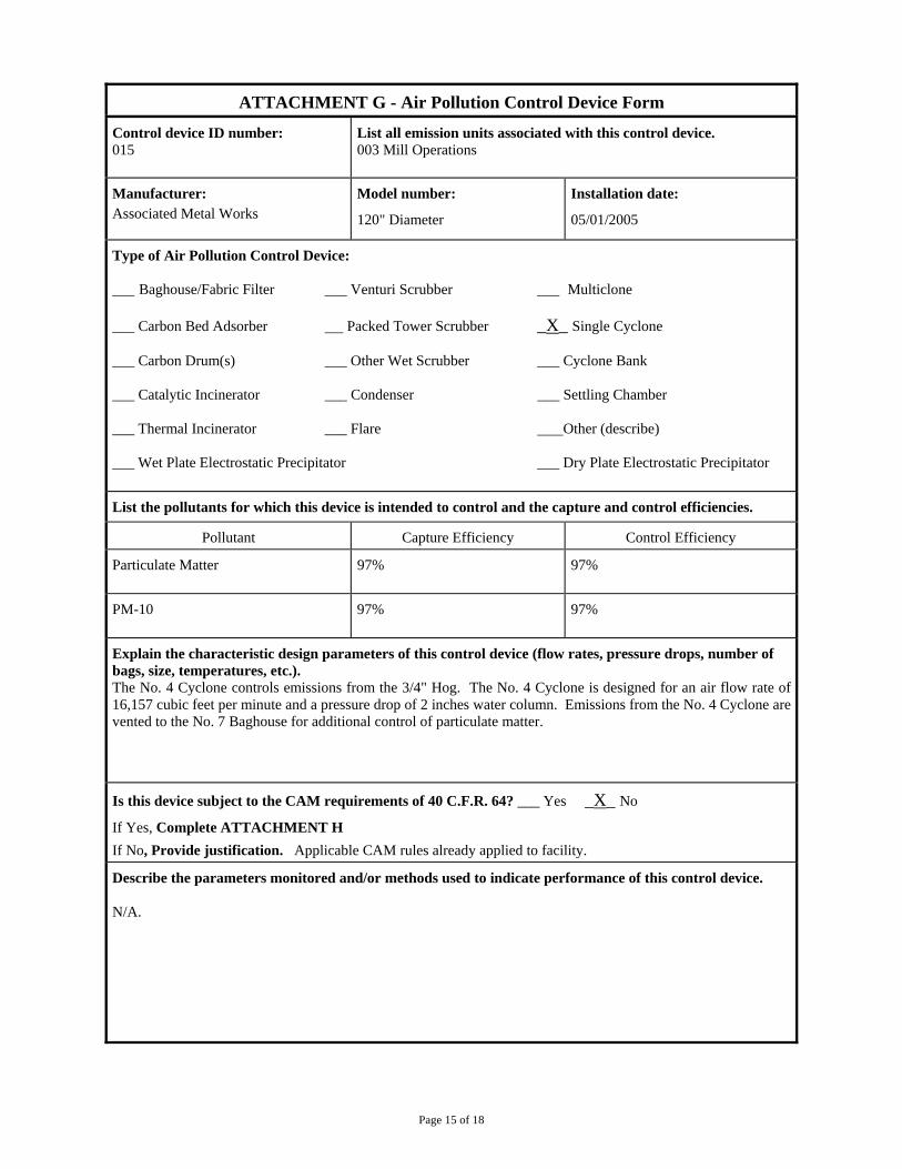
Page 15 of 18
ATTACHMENT G - Air Pollution Control Device Form
Control device ID number: 015
List all emission units associated with this control device. 003 Mill Operations
Manufacturer: Associated Metal Works
Model number:
120" Diameter
Installation date:
05/01/2005
Type of Air Pollution Control Device: ___ Baghouse/Fabric Filter ___ Venturi Scrubber ___ Multiclone ___ Carbon Bed Adsorber Packed Tower Scrubber _X_ Single Cyclone ___ Carbon Drum(s) ___ Other Wet Scrubber ___ Cyclone Bank ___ Catalytic Incinerator ___ Condenser ___ Settling Chamber ___ Thermal Incinerator ___ Flare Other (describe) ___ Wet Plate Electrostatic Precipitator ___ Dry Plate Electrostatic Precipitator
List the pollutants for which this device is intended to control and the capture and control efficiencies.
Pollutant Capture Efficiency Control Efficiency
Particulate Matter 97% 97%
PM-10 97% 97%
Explain the characteristic design parameters of this control device (flow rates, pressure drops, number of bags, size, temperatures, etc.). The No. 4 Cyclone controls emissions from the 3/4" Hog. The No. 4 Cyclone is designed for an air flow rate of 16,157 cubic feet per minute and a pressure drop of 2 inches water column. Emissions from the No. 4 Cyclone are vented to the No. 7 Baghouse for additional control of particulate matter.
Is this device subject to the CAM requirements of 40 C.F.R. 64? ___ Yes _X_ No
If Yes, Complete ATTACHMENT H
If No, Provide justification. Applicable CAM rules already applied to facility.
Describe the parameters monitored and/or methods used to indicate performance of this control device. N/A.
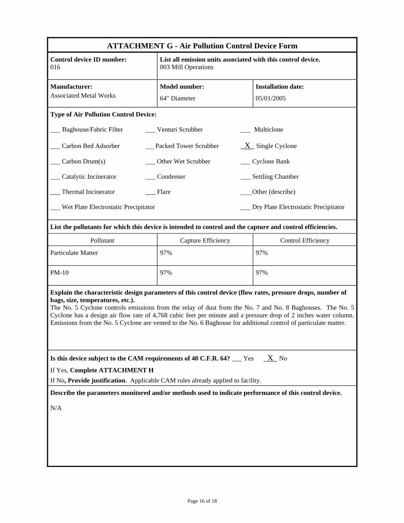
Page 16 of 18
ATTACHMENT G - Air Pollution Control Device Form
Control device ID number: 016
List all emission units associated with this control device. 003 Mill Operations
Manufacturer: Associated Metal Works
Model number:
64" Diameter
Installation date:
05/01/2005
Type of Air Pollution Control Device: ___ Baghouse/Fabric Filter ___ Venturi Scrubber ___ Multiclone ___ Carbon Bed Adsorber Packed Tower Scrubber _X_ Single Cyclone ___ Carbon Drum(s) ___ Other Wet Scrubber ___ Cyclone Bank ___ Catalytic Incinerator ___ Condenser ___ Settling Chamber ___ Thermal Incinerator ___ Flare Other (describe) ___ Wet Plate Electrostatic Precipitator ___ Dry Plate Electrostatic Precipitator
List the pollutants for which this device is intended to control and the capture and control efficiencies.
Pollutant Capture Efficiency Control Efficiency
Particulate Matter 97% 97%
PM-10 97% 97%
Explain the characteristic design parameters of this control device (flow rates, pressure drops, number of bags, size, temperatures, etc.). The No. 5 Cyclone controls emissions from the relay of dust from the No. 7 and No. 8 Baghouses. The No. 5 Cyclone has a design air flow rate of 4,768 cubic feet per minute and a pressure drop of 2 inches water column. Emissions from the No. 5 Cyclone are vented to the No. 6 Baghouse for additional control of particulate matter.
Is this device subject to the CAM requirements of 40 C.F.R. 64? ___ Yes _X_ No
If Yes, Complete ATTACHMENT H
If No, Provide justification. Applicable CAM rules already applied to facility.
Describe the parameters monitored and/or methods used to indicate performance of this control device. N/A

Page 17 of 18
ATTACHMENT G - Air Pollution Control Device Form
Control device ID number: 017
List all emission units associated with this control device. 003 Mill Operations
Manufacturer: Associated Metal Works
Model number:
152" Diameter
Installation date:
05/01/2005
Type of Air Pollution Control Device: ___ Baghouse/Fabric Filter ___ Venturi Scrubber ___ Multiclone ___ Carbon Bed Adsorber Packed Tower Scrubber _X_ Single Cyclone ___ Carbon Drum(s) ___ Other Wet Scrubber ___ Cyclone Bank ___ Catalytic Incinerator ___ Condenser ___ Settling Chamber ___ Thermal Incinerator ___ Flare Other (describe) ___ Wet Plate Electrostatic Precipitator ___ Dry Plate Electrostatic Precipitator
List the pollutants for which this device is intended to control and the capture and control efficiencies.
Pollutant Capture Efficiency Control Efficiency
Particulate Matter 97% 97%
PM-10 97% 97%
Explain the characteristic design parameters of this control device (flow rates, pressure drops, number of bags, size, temperatures, etc.). The No. 6 Cyclone controls emissions from the relay of dust from the Nos. 1, 2, 3, 4, & 5 Baghouses. The No. 6 Cyclone has a design air flow rate of 27,490 cubic feet per minute and a pressure drop of 2 inches water column. Emissions from the No. 6 Cyclone are vented to the No. 6 Baghouse for additional control of particulate matter.
Is this device subject to the CAM requirements of 40 C.F.R. 64? ___ Yes _X_ No
If Yes, Complete ATTACHMENT H
If No, Provide justification. Applicable CAM rules already applied to facility.
Describe the parameters monitored and/or methods used to indicate performance of this control device. N/A

Page 18 of 18
ATTACHMENT G - Air Pollution Control Device Form
Control device ID number: 018
List all emission units associated with this control device. 003 Mill Operations
Manufacturer: Unknown
Model number:
Unknown
Installation date:
06/06.1990
Type of Air Pollution Control Device: ___ Baghouse/Fabric Filter ___ Venturi Scrubber ___ Multiclone ___ Carbon Bed Adsorber Packed Tower Scrubber _X_ Single Cyclone ___ Carbon Drum(s) ___ Other Wet Scrubber ___ Cyclone Bank ___ Catalytic Incinerator ___ Condenser ___ Settling Chamber ___ Thermal Incinerator ___ Flare Other (describe) ___ Wet Plate Electrostatic Precipitator ___ Dry Plate Electrostatic Precipitator
List the pollutants for which this device is intended to control and the capture and control efficiencies.
Pollutant Capture Efficiency Control Efficiency
Particulate Matter 95% 95%
PM-10 95% 95%
Explain the characteristic design parameters of this control device (flow rates, pressure drops, number of bags, size, temperatures, etc.). The No. 7 Cyclone controls emissions from the transfer of hogged fuel from the silos to the metering bins for the No. 1 and No. 2 Boilers. Exhaust air from the cyclone is returned to the silo relay system for transport of hogged fuel to the metering bins. The cyclone has an estimated design air flow rate of 24,100 cubic feet per minute.
Is this device subject to the CAM requirements of 40 C.F.R. 64? ___ Yes _X_ No
If Yes, Complete ATTACHMENT H
If No, Provide justification. Applicable CAM rules already applied to facility
Describe the parameters monitored and/or methods used to indicate performance of this control device. N/A
Attachment H
Compliance Assurance Monitoring
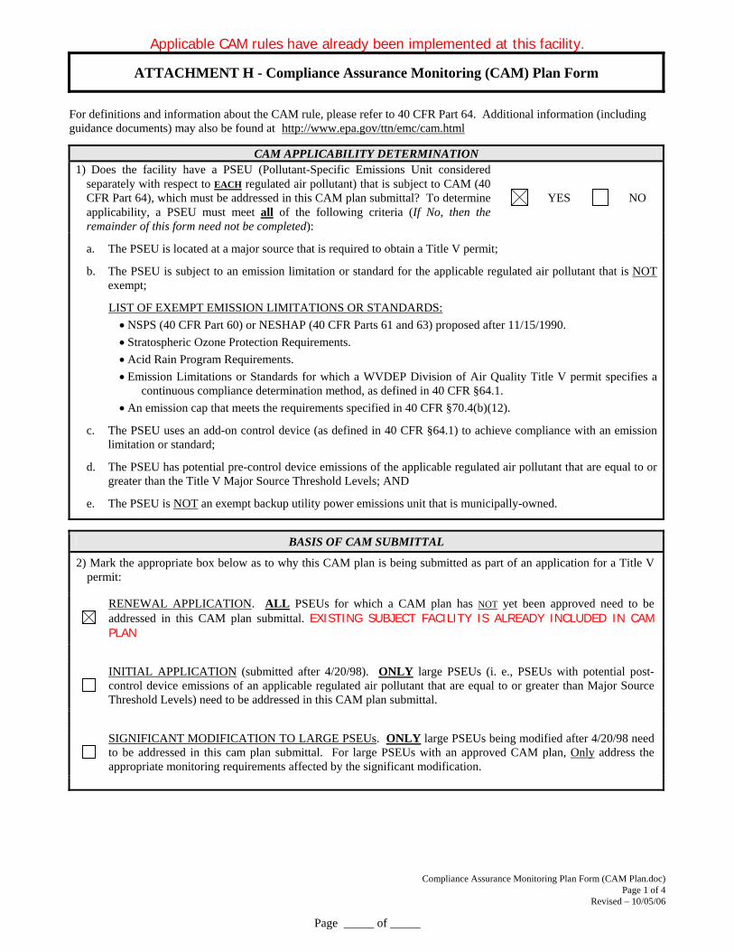
Applicable CAM rules have already been implemented at this facility.
Compliance Assurance Monitoring Plan Form (CAM Plan.doc) Page 1 of 4
Revised – 10/05/06
Page _____ of _____
ATTACHMENT H - Compliance Assurance Monitoring (CAM) Plan Form
For definitions and information about the CAM rule, please refer to 40 CFR Part 64. Additional information (including guidance documents) may also be found at http://www.epa.gov/ttn/emc/cam.html
CAM APPLICABILITY DETERMINATION
1) Does the facility have a PSEU (Pollutant-Specific Emissions Unit considered separately with respect to EACH regulated air pollutant) that is subject to CAM (40 CFR Part 64), which must be addressed in this CAM plan submittal? To determine applicability, a PSEU must meet all of the following criteria (If No, then the remainder of this form need not be completed):
YES NO
a. The PSEU is located at a major source that is required to obtain a Title V permit;
b. The PSEU is subject to an emission limitation or standard for the applicable regulated air pollutant that is NOT exempt;
LIST OF EXEMPT EMISSION LIMITATIONS OR STANDARDS:
NSPS (40 CFR Part 60) or NESHAP (40 CFR Parts 61 and 63) proposed after 11/15/1990.
Stratospheric Ozone Protection Requirements.
Acid Rain Program Requirements.
Emission Limitations or Standards for which a WVDEP Division of Air Quality Title V permit specifies a continuous compliance determination method, as defined in 40 CFR §64.1.
An emission cap that meets the requirements specified in 40 CFR §70.4(b)(12).
c. The PSEU uses an add-on control device (as defined in 40 CFR §64.1) to achieve compliance with an emission limitation or standard;
d. The PSEU has potential pre-control device emissions of the applicable regulated air pollutant that are equal to or greater than the Title V Major Source Threshold Levels; AND
e. The PSEU is NOT an exempt backup utility power emissions unit that is municipally-owned.
BASIS OF CAM SUBMITTAL
2) Mark the appropriate box below as to why this CAM plan is being submitted as part of an application for a Title V permit:
RENEWAL APPLICATION. ALL PSEUs for which a CAM plan has NOT yet been approved need to be addressed in this CAM plan submittal. EXISTING SUBJECT FACILITY IS ALREADY INCLUDED IN CAM PLAN
INITIAL APPLICATION (submitted after 4/20/98). ONLY large PSEUs (i. e., PSEUs with potential post-control device emissions of an applicable regulated air pollutant that are equal to or greater than Major Source Threshold Levels) need to be addressed in this CAM plan submittal.
SIGNIFICANT MODIFICATION TO LARGE PSEUs. ONLY large PSEUs being modified after 4/20/98 need to be addressed in this cam plan submittal. For large PSEUs with an approved CAM plan, Only address the appropriate monitoring requirements affected by the significant modification.
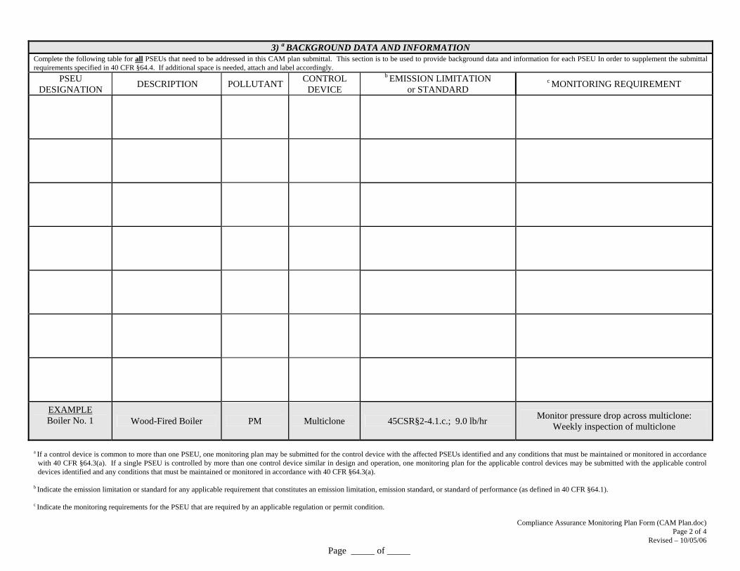
3) a BACKGROUND DATA AND INFORMATION
Complete the following table for all PSEUs that need to be addressed in this CAM plan submittal. This section is to be used to provide background data and information for each PSEU In order to supplement the submittal requirements specified in 40 CFR §64.4. If additional space is needed, attach and label accordingly.
PSEU DESIGNATION
DESCRIPTION POLLUTANT CONTROL
DEVICE
b EMISSION LIMITATION or STANDARD
c MONITORING REQUIREMENT
EXAMPLE Boiler No. 1 Wood-Fired Boiler PM Multiclone 45CSR§2-4.1.c.; 9.0 lb/hr
Monitor pressure drop across multiclone: Weekly inspection of multiclone
a If a control device is common to more than one PSEU, one monitoring plan may be submitted for the control device with the affected PSEUs identified and any conditions that must be maintained or monitored in accordance
with 40 CFR §64.3(a). If a single PSEU is controlled by more than one control device similar in design and operation, one monitoring plan for the applicable control devices may be submitted with the applicable control devices identified and any conditions that must be maintained or monitored in accordance with 40 CFR §64.3(a).
b Indicate the emission limitation or standard for any applicable requirement that constitutes an emission limitation, emission standard, or standard of performance (as defined in 40 CFR §64.1). c Indicate the monitoring requirements for the PSEU that are required by an applicable regulation or permit condition.
Compliance Assurance Monitoring Plan Form (CAM Plan.doc) Page 2 of 4
Revised – 10/05/06
Page _____ of _____
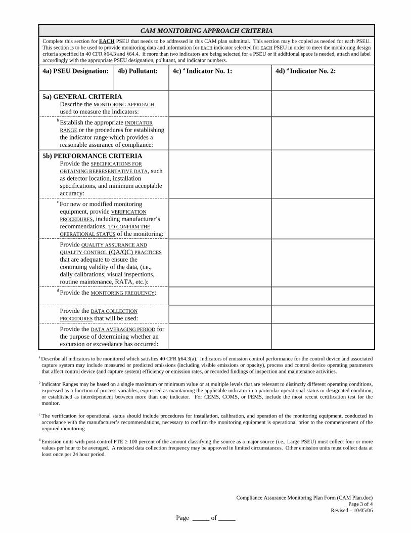
Compliance Assurance Monitoring Plan Form (CAM Plan.doc) Page 3 of 4
Revised – 10/05/06
Page _____ of _____
CAM MONITORING APPROACH CRITERIA
Complete this section for EACH PSEU that needs to be addressed in this CAM plan submittal. This section may be copied as needed for each PSEU. This section is to be used to provide monitoring data and information for EACH indicator selected for EACH PSEU in order to meet the monitoring design criteria specified in 40 CFR §64.3 and §64.4. if more than two indicators are being selected for a PSEU or if additional space is needed, attach and label accordingly with the appropriate PSEU designation, pollutant, and indicator numbers.
4a) PSEU Designation:
4b) Pollutant:
4c) a Indicator No. 1:
4d) a Indicator No. 2:
5a) GENERAL CRITERIA Describe the MONITORING APPROACH used to measure the indicators:
b Establish the appropriate INDICATOR
RANGE or the procedures for establishing the indicator range which provides a reasonable assurance of compliance:
5b) PERFORMANCE CRITERIA Provide the SPECIFICATIONS FOR
OBTAINING REPRESENTATIVE DATA, such as detector location, installation specifications, and minimum acceptable accuracy:
c For new or modified monitoring equipment, provide VERIFICATION
PROCEDURES, including manufacturer’s recommendations, TO CONFIRM THE
OPERATIONAL STATUS of the monitoring:
Provide QUALITY ASSURANCE AND
QUALITY CONTROL (QA/QC) PRACTICES that are adequate to ensure the continuing validity of the data, (i.e., daily calibrations, visual inspections, routine maintenance, RATA, etc.):
d Provide the MONITORING FREQUENCY:
Provide the DATA COLLECTION
PROCEDURES that will be used:
Provide the DATA AVERAGING PERIOD for the purpose of determining whether an excursion or exceedance has occurred:
a Describe all indicators to be monitored which satisfies 40 CFR §64.3(a). Indicators of emission control performance for the control device and associated capture system may include measured or predicted emissions (including visible emissions or opacity), process and control device operating parameters that affect control device (and capture system) efficiency or emission rates, or recorded findings of inspection and maintenance activities.
b Indicator Ranges may be based on a single maximum or minimum value or at multiple levels that are relevant to distinctly different operating conditions, expressed as a function of process variables, expressed as maintaining the applicable indicator in a particular operational status or designated condition, or established as interdependent between more than one indicator. For CEMS, COMS, or PEMS, include the most recent certification test for the monitor.
c The verification for operational status should include procedures for installation, calibration, and operation of the monitoring equipment, conducted in
accordance with the manufacturer’s recommendations, necessary to confirm the monitoring equipment is operational prior to the commencement of the required monitoring.
d Emission units with post-control PTE 100 percent of the amount classifying the source as a major source (i.e., Large PSEU) must collect four or more
values per hour to be averaged. A reduced data collection frequency may be approved in limited circumstances. Other emission units must collect data at least once per 24 hour period.
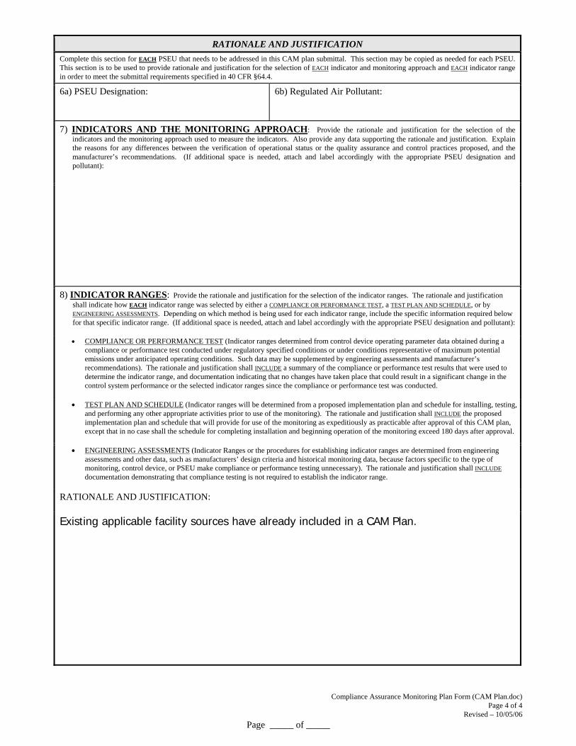
Compliance Assurance Monitoring Plan Form (CAM Plan.doc) Page 4 of 4
Revised – 10/05/06
Page _____ of _____
RATIONALE AND JUSTIFICATION
Complete this section for EACH PSEU that needs to be addressed in this CAM plan submittal. This section may be copied as needed for each PSEU. This section is to be used to provide rationale and justification for the selection of EACH indicator and monitoring approach and EACH indicator range in order to meet the submittal requirements specified in 40 CFR §64.4.
6a) PSEU Designation:
6b) Regulated Air Pollutant:
7) INDICATORS AND THE MONITORING APPROACH: Provide the rationale and justification for the selection of the indicators and the monitoring approach used to measure the indicators. Also provide any data supporting the rationale and justification. Explain the reasons for any differences between the verification of operational status or the quality assurance and control practices proposed, and the manufacturer’s recommendations. (If additional space is needed, attach and label accordingly with the appropriate PSEU designation and pollutant):
8) INDICATOR RANGES: Provide the rationale and justification for the selection of the indicator ranges. The rationale and justification shall indicate how EACH indicator range was selected by either a COMPLIANCE OR PERFORMANCE TEST, a TEST PLAN AND SCHEDULE, or by ENGINEERING ASSESSMENTS. Depending on which method is being used for each indicator range, include the specific information required below for that specific indicator range. (If additional space is needed, attach and label accordingly with the appropriate PSEU designation and pollutant):
COMPLIANCE OR PERFORMANCE TEST (Indicator ranges determined from control device operating parameter data obtained during a compliance or performance test conducted under regulatory specified conditions or under conditions representative of maximum potential emissions under anticipated operating conditions. Such data may be supplemented by engineering assessments and manufacturer’s recommendations). The rationale and justification shall INCLUDE a summary of the compliance or performance test results that were used to determine the indicator range, and documentation indicating that no changes have taken place that could result in a significant change in the control system performance or the selected indicator ranges since the compliance or performance test was conducted.
TEST PLAN AND SCHEDULE (Indicator ranges will be determined from a proposed implementation plan and schedule for installing, testing, and performing any other appropriate activities prior to use of the monitoring). The rationale and justification shall INCLUDE the proposed implementation plan and schedule that will provide for use of the monitoring as expeditiously as practicable after approval of this CAM plan, except that in no case shall the schedule for completing installation and beginning operation of the monitoring exceed 180 days after approval.
ENGINEERING ASSESSMENTS (Indicator Ranges or the procedures for establishing indicator ranges are determined from engineering assessments and other data, such as manufacturers’ design criteria and historical monitoring data, because factors specific to the type of monitoring, control device, or PSEU make compliance or performance testing unnecessary). The rationale and justification shall INCLUDE documentation demonstrating that compliance testing is not required to establish the indicator range.
RATIONALE AND JUSTIFICATION:
Existing applicable facility sources have already included in a CAM Plan.