(pbee) to caltrans
TRANSCRIPT
Application of Performance Based Earthquake Engineering (PBEE)
to Caltrans Ordinary Standard Bridge Design
1
California Dep. of Transportation Structures Policy and Innovation Office of Earthquake Engineering
Background
1. External
Seismic Advisory Board
2. Internal
PDCA
2

Approach, Theoretical Background And Research Needs
3
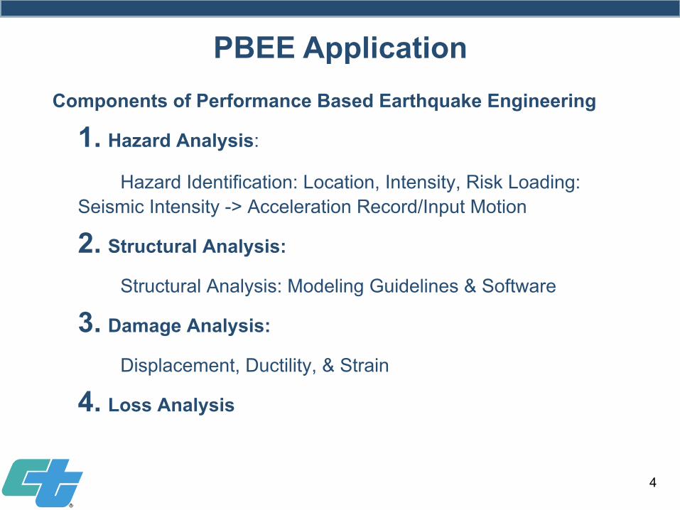
PBEE Application Components of Performance Based Earthquake Engineering
1. Hazard Analysis:
Hazard Identification: Location, Intensity, Risk Loading: Seismic Intensity -> Acceleration Record/Input Motion
2. Structural Analysis:
Structural Analysis: Modeling Guidelines & Software
3. Damage Analysis:
Displacement, Ductility, & Strain
4. Loss Analysis
4
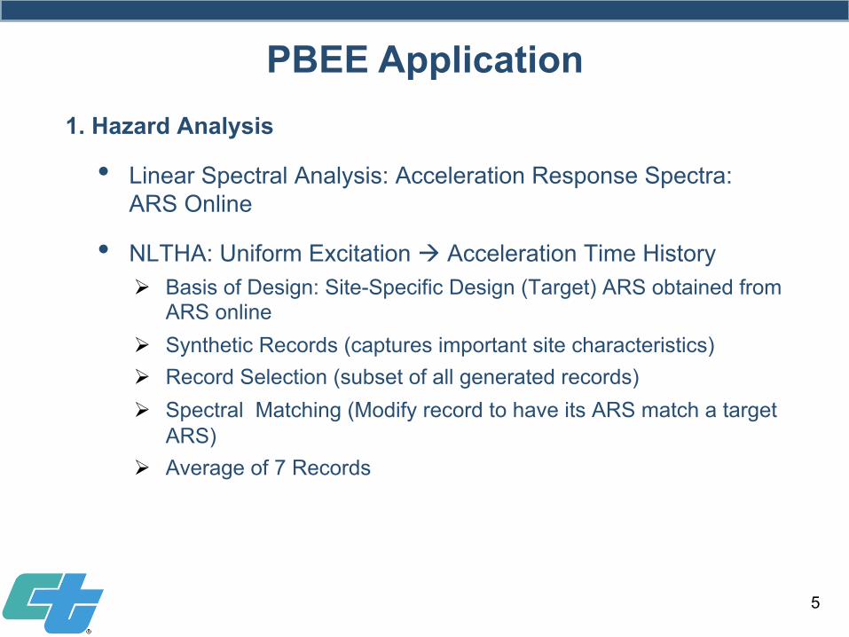
PBEE Application 1. Hazard Analysis
• Linear Spectral Analysis: Acceleration Response Spectra: ARS Online
• NLTHA: Uniform Excitation à Acceleration Time History Ø Basis of Design: Site-Specific Design (Target) ARS obtained from
ARS online Ø Synthetic Records (captures important site characteristics) Ø Record Selection (subset of all generated records) Ø Spectral Matching (Modify record to have its ARS match a target
ARS) Ø Average of 7 Records
5
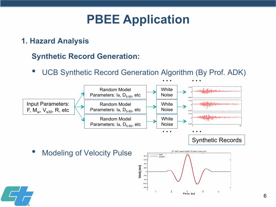
Synthetic Record Generation:
• UCB Synthetic Record Generation Algorithm (By Prof. ADK)
• Modeling of Velocity Pulse
Synthetic Records …
-0.25
0
0.15
0 -0.25
0
0.15
-0.25
0
0.15
40
Input Parameters: F, Mw, Vs30, R, etc
Random Model Parameters: Ia, D5-95, etc
White Noise
…
… …
6
Random Model Parameters: Ia, D5-95, etc
White Noise
Random Model Parameters: Ia, D5-95, etc
White Noise
PBEE Application 1. Hazard Analysis
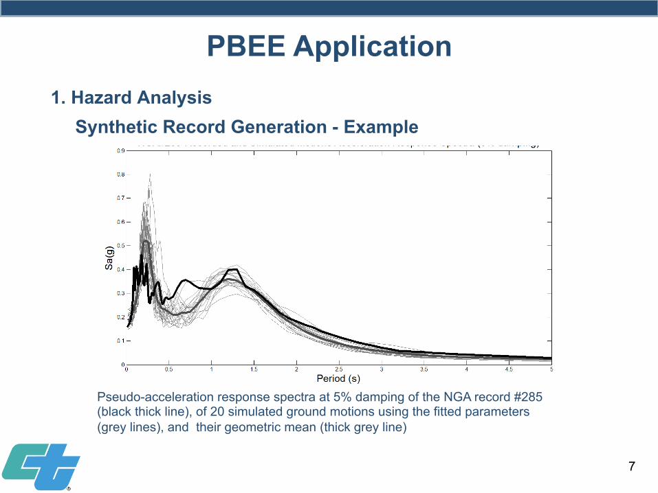
Synthetic Record Generation - Example
Pseudo-acceleration response spectra at 5% damping of the NGA record #285 (black thick line), of 20 simulated ground motions using the fitted parameters (grey lines), and their geometric mean (thick grey line)
7
PBEE Application 1. Hazard Analysis
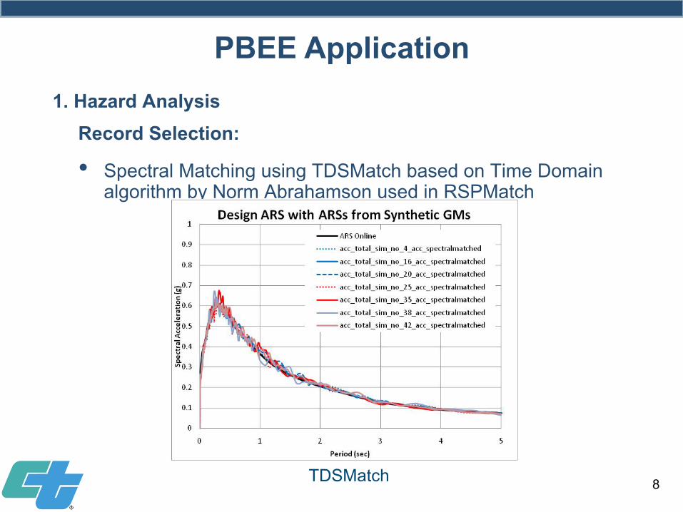
Record Selection:
• Spectral Matching using TDSMatch based on Time Domain algorithm by Norm Abrahamson used in RSPMatch
TDSMatch 8
PBEE Application 1. Hazard Analysis
Input Motion Generation/Selection:
• Generate Design ARS from ARS Online (Target ARS), based on 1000-year return period
• Generate Synthetic Records: 50 Records (with near field velocity pulse if near field effect is needed)
• Select 7 records (from set of 50) with closest match to target ARS within 0.5 < T < 3.0 seconds
• Scale Records: Use TDSMatch to adjust the 7 selected records to the target ARS
• Use the adjusted records for analysis
9
PBEE Application 1. Hazard Analysis – Where we are:
Input Motion Generation/Selection:
• Generating Synthetic motions in two directions
• Generating motions with hazard intensities and variations to warrant use in design without considering ARS
• Near-field and pulse consideration
• Fault Crossing
• Directionality
10
PBEE Application 1. Hazard Analysis – Where we are headed (Our Needs)
Nonlinear Time History Analysis (NLTHA):
• Bridge Behavior in Seismic event is NONLINEAR
• NLTHA is the most accurate method available
• Current tools are efficient enough for NLTHA
• Response Spectrum Analysis does not capture some key nonlinear responses (e.g., column plastic hinge, span hinge, shear key, abutment response, & isolation bearing)
• Equal displacement principal is an approximation
11
PBEE Application 2. Structural Analysis
What is needed for Nonlinear Time History Analysis:
• Loading Guidelines (i.e., Acceleration Time History Records): Ø Intensity, peak acceleration, #of peaks Ø Duration Ø Frequency content Ø Near-Field Effect
• Modeling Guidelines: PEER 2008-03
• Reliable Software: CSI-Bridge, OpenSees, & Midas-Civil
• Acceptance Criteria: Δcapacity/Δdemand, Ductility, etc.
12
PBEE Application 2. Structural Analysis
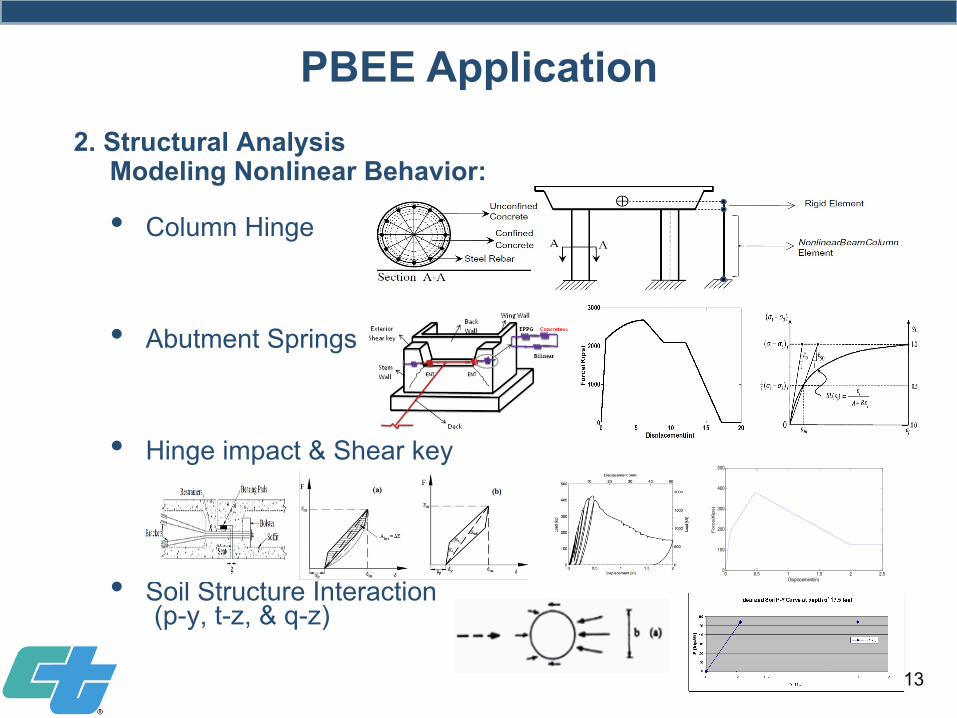
Modeling Nonlinear Behavior:
• Column Hinge
• Abutment Springs
• Hinge impact & Shear key
• Soil Structure Interaction (p-y, t-z, & q-z)
0 0.5 1 1.5 2 2.50
100
200
300
400
500
Displacement(in)
Force(Kips)
13
PBEE Application 2. Structural Analysis
Response Calculation:
• Apply each input motion in longitudinal and transverse directions (and more directions if curved or highly skewed)
• Record maximum displacements in longitudinal and transverse directions
• Calculate average of the maximum displacements (in each direction) as displacement demand
14
Capacity Calculation:
• Perform push-over analysis in longitudinal and transverse directions
• Calculate displacement capacity based on strain limits given in SDC
PBEE Application 2. Structural Analysis – Where we are:
Response Calculation:
• Formal guidance for THA
• Better quantification of damping
• Better modeling of various nonlinear elements
• Improved tools for analysis
15
PBEE Application 2. Structural Analysis – Where we are headed (Our Needs):
Acceptance Criteria / Damage Assessment:
• Displacement-based, Current SDC Limits: Ø Δdemand = average Δmax.col of each column Ø Δcapacity = From Push-over analysis of bent or frame
• Damage Index Evaluation: Ø PDCA: Column damage index based on strain
16
PBEE Application 3. Damage Analysis: Where we are:
Capacity Calculation: • Perform push-over analysis in longitudinal and transverse
directions • Calculate displacement capacity based on strain limits
given in SDC
Possible Future Acceptance Criteria / Damage Assessment:
• No Push-over Analysis needed, instead calculate the ultimate curvature for each plastic hinge
• Compare Curvature demand and capacity: Ø Yield curvature = φy, based on SDC idealized M-φ curve
Ø Curvature demand = φd = Average of maximum curvatures of the 7 analysis cases
Ø Curvature capacity = φc (based on SDC strain limits), i.e.: φd < φc
Ø Curvature Ductility: φc / φy > 10 (using SDC values)
• Identify Damage Index: Ø Curvature demand à Max strain demand à Damage
Index 17
PBEE Application 3. Damage Analysis: Where we are headed (Research Needs):
Possible Future Acceptance Criteria / Damage Assessment:
18
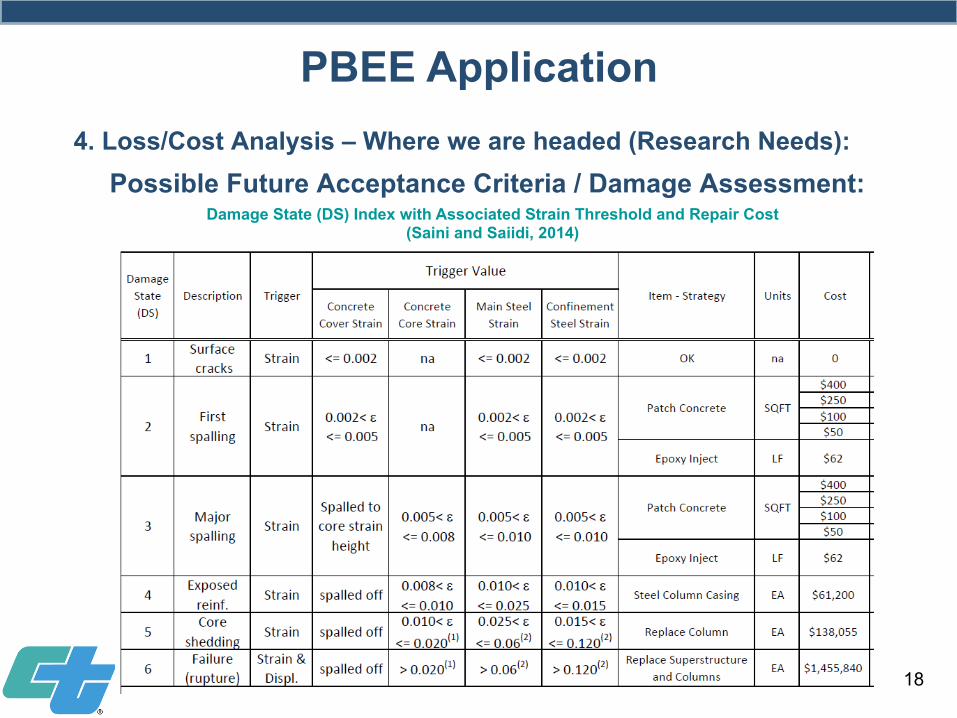
PBEE Application 4. Loss/Cost Analysis – Where we are headed (Research Needs):
Damage State (DS) Index with Associated Strain Threshold and Repair Cost (Saini and Saiidi, 2014)
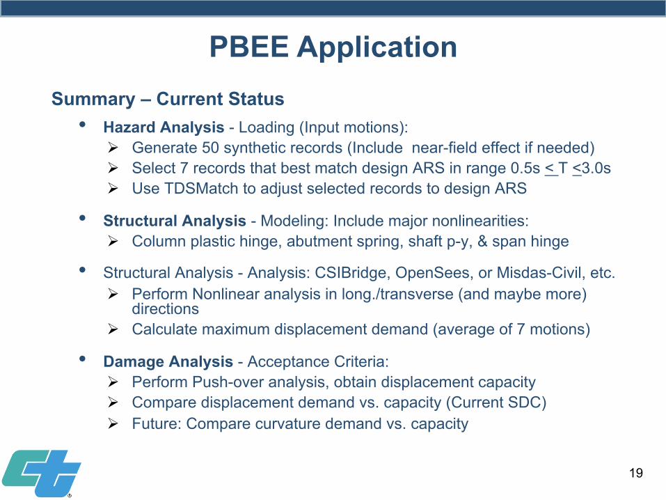
• Hazard Analysis - Loading (Input motions): Ø Generate 50 synthetic records (Include near-field effect if needed) Ø Select 7 records that best match design ARS in range 0.5s < T <3.0s Ø Use TDSMatch to adjust selected records to design ARS
• Structural Analysis - Modeling: Include major nonlinearities: Ø Column plastic hinge, abutment spring, shaft p-y, & span hinge
• Structural Analysis - Analysis: CSIBridge, OpenSees, or Misdas-Civil, etc. Ø Perform Nonlinear analysis in long./transverse (and maybe more)
directions Ø Calculate maximum displacement demand (average of 7 motions)
• Damage Analysis - Acceptance Criteria: Ø Perform Push-over analysis, obtain displacement capacity Ø Compare displacement demand vs. capacity (Current SDC) Ø Future: Compare curvature demand vs. capacity
19
PBEE Application Summary – Current Status
4.1: Loss quantification
Function of Interest Rate ?
4.2: Performance Measure
Cost
Time
Fatalities
Sustainability (Mackie)
20
PBEE - Bridges 4. Loss Analysis / Performance Measure – Future