oracle zfs storage appliance reference architecture for ... · oracle zfs storage appliance...
TRANSCRIPT

An Oracle Technical White Paper December 2013; v1.2
Oracle ZFS Storage Appliance Reference Architecture for VMware vSphere4

Oracle ZFS Storage Appliance Reference Architecture for VMware vSphere4
Introduction ......................................................................................... 2 About the Oracle ZFS Storage Appliance........................................... 3 About VMware vSphere ...................................................................... 3 Reference Architecture Overview ....................................................... 4
Architectural Components............................................................... 5 Reference Architecture Design ....................................................... 7 Partition Alignment ........................................................................ 10 Application Performance Validation .............................................. 12 Microsoft Exchange Server Jetstress Validation........................... 12 OLTP Database Validation ........................................................... 13 DSS Database Validation ............................................................. 15
Conclusion ........................................................................................ 16

Oracle ZFS Storage Appliance Reference Architecture for VMware vSphere4
2
Introduction
The reference architecture described in this paper demonstrates the design and testing of an Oracle
ZFS Storage Appliance configuration featuring the VMware vSphere 4 virtualization platform. It is
intended to help IT administrators plan a virtualization deployment with confidence that the
configuration will meet their IT and business needs.
This reference architecture highlights a multi-application deployment of mail servers, database servers,
web servers, and various development and test servers. A multipool approach is used to help
consolidate and scale differing workloads on a single storage platform while maintaining performance
levels and meeting service level agreement (SLA) requirements for each application.
Highlighted in this paper are:
• A multipool design with multiple data store repositories in VMware vSphere 4
• Use of the Oracle ZFS Storage Appliance Hybrid Storage Pool with flash media
• A high availability design for storage access and performance
• The importance of partition alignment in VMware
• Test validation of the reference architecture
The key components of the reference architecture described in this paper are:
• Sun ZFS Storage 7420 cluster
• VMware vSphere 4
NOTE: References to Sun ZFS Storage Appliance, Sun ZFS Storage 7000 series, and ZFS Storage Appliance all refer to the same family of Oracle ZFS Storage Appliance products.

Oracle ZFS Storage Appliance Reference Architecture for VMware vSphere4
3
About the Oracle ZFS Storage Appliance
The Oracle ZFS Storage Appliance offers innovations in storage that include a DTrace-based storage analytics tool, flash-based Hybrid Storage Pools, enterprise-class data services, massive scalability, and a choice of storage protocols, while delivering significant cost savings. The Oracle ZFS Storage Appliance features a common, easy-to-use management interface that has the industry’s most comprehensive analytics environment to help isolate and resolve issues to minimize business impact.
Oracle offers several models of the Oracle ZFS Storage Appliance to meet the scalability and availability needs of today’s demanding applications. All of the Oracle ZFS Storage Appliance models utilize a common storage software foundation, and some offer up to 2 TB of read cache, enabling a typical appliance response time in the low single digit milliseconds. Write flash, available on all the platforms, enables response times of less than one millisecond for synchronous writes.
The latest Oracle ZFS Storage Appliance platforms offer faster CPUs, bigger flash cache, larger storage capacity, and better throughput to meet the storage requirements of mission-critical applications.
About VMware vSphere
VMware vSphere, the industry’s first cloud operating system, leverages the power of virtualization to transform data centers into dramatically simplified cloud computing infrastructures. VMware vSphere helps preserve business-critical application availability by enabling transparent migration of applications and files from one storage array to another. IT organizations can deliver the next generation of flexible and reliable IT services, using internal and external resources securely and with low risk. Key benefits of vSphere include:
• Broad interoperability across servers, storage, operating systems, and applications
• A robust, reliable foundation
• An established install base

Oracle ZFS Storage Appliance Reference Architecture for VMware vSphere4
4
Reference Architecture Overview
Figure 1 shows a high-level overview of the physical components of the reference architecture. The reference configuration consists of two physical VMware ESX 4.1 servers, a 10 GbE network infrastructure, and Oracle's Sun ZFS Storage 7420 with six disk shelves. A total of 24 virtual machines are configured in the architecture and are running a mail server workload, an online transaction processing (OLTP) database workload, and a decision support system (DSS) database workload.
Figure 1. Physical components of the reference architecture

Oracle ZFS Storage Appliance Reference Architecture for VMware vSphere4
5
Architectural Components
The following tables describe the hardware, virtual machine, and software components of the reference architecture.
Table 1 shows the hardware components used.
TABLE 1. HARDWARE COMPONENTS USED IN REFERENCE ARCHITECTURE
EQUIPMENT QUANTITY CONFIGURATION
Primary storage 1 cluster (2
controllers)
Sun ZFS Storage 7420 cluster
256 GB DRAM per controller
2 x 512 GB read cache SSD per controller
2 x 20 2 TB SAS-2 disk trays
4 x 24 2 TB SAS-2 disk trays
8 x 18 GB write cache SSD
2 x dual port 10 GbE NIC
Network 2 10 GbE network switch
Server 2 Sun Fire X4170 M2 Server
72 GB DRAM
2 internal HDDs
1 x dual port 10 GbE NIC
Table 2 shows the virtual machine components used.
TABLE 2. VIRTUAL MACHINE COMPONENTS USED IN REFERENCE ARCHITECTURE
OPERATING
SYSTEM
QUANTITY CONFIGURATION
Microsoft
Windows
2008 R2 (x64)
12 2 Microsoft Exchange Servers
4 Mail Utility servers
5 Windows development and test servers
1 domain controller
Oracle Linux
5.4
12 2 OLTP database servers
2 DSS database servers
4 database utility servers
4 development and test servers

Oracle ZFS Storage Appliance Reference Architecture for VMware vSphere4
6
Table 3 shows the software components used.
TABLE 3. SOFTWARE COMPONENTS USED IN REFERENCE ARCHITECTURE
SOFTWARE VERSION
Oracle ZFS Storage Appliance software 2010.Q3.3
Microsoft Exchange Server Jetstress verification tool 2010 (x64)
Oracle ORION I/O calibration tool 11.1.0.7.0
VMware vCenter Virtualization Management software 4.1.0 (Build 258902)
VMware ESX Hypervisor software 4.1.0 (Build 260247)

Oracle ZFS Storage Appliance Reference Architecture for VMware vSphere4
7
Reference Architecture Design
In the reference architecture, the VMware ESX Hypervisor accesses the Sun ZFS Storage 7420 using Network File System (NFS) protocol over a 10 GbE interface. The Sun ZFS Storage 7420 cluster provides two separate controllers that can be configured in an Active/Active cluster implementation to provide simultaneous access by both controllers to the workload.
A primary consideration in performance and capacity planning is the storage pool layout of the disk trays. Six disk trays are used in the reference configuration, with three trays of disks configured for each controller. The six trays are configured as shown in Table 4.
TABLE 4. POOL LAYOUT OF DISK TRAYS
POOL NAME / CONTROLLER
ASSIGNMENT
POOL CONFIGURATION POOL USE
Pool1 – Controller1 Double-parity RAID
6 data disks, 1 write SSD, 0 read cache SSD
Microsoft Windows virtual machine
boot drive virtual disks
Pool2 – Controller1 Mirrored
44 data disks, 2 write SSDs, 2 read cache SSDs
Microsoft Exchange Server database
virtual disks
Pool3 – Controller1 Mirrored
18 data disks, 1 write SSD, 0 read cache SSD
MS Exchange Server log virtual disks
Pool4 – Controller2 Double-parity RAID
6 data disks, 1 write SSD, 0 read cache SSD
Oracle Linux virtual machine boot
drive virtual disks
Pool5 – Controller2 Mirrored
44 data disks, 2 write SSDs, 2 read cache SSDs
OLTP database virtual disks
Pool6 – Controller2 Double-parity RAID
18 data disks, 1 write SSD, 0 read cache SSD
DSS database virtual disks
As shown in Table 4, the virtual boot disks for both the Windows virtual machines and Oracle Linux virtual machines and the DSS database virtual disks are stored in pools configured as double-parity RAID. These virtual disks do not require high random read performance but instead must be configured to maximize sequential, large block I/O performance.
The Microsoft Exchange Server database files, log files and the OLTP database files are stored in pools that are configured for mirrored protection. Mirrored pools are preferred when the application or virtual machine requires a high degree of small block, random read I/O with low latency. Such a layout may not be necessary in all deployments, as multiple workloads could be serviced from a single large pool. However, this layout is used to demonstrate a segregated configuration to facilitate guaranteed quality of service and performance requirements.
Additionally, the Windows virtual boot disks are stored in pools owned by the same controller as the pools for the Windows application virtual disks and the Oracle Linux virtual boot disks are stored in

Oracle ZFS Storage Appliance Reference Architecture for VMware vSphere4
8
pools owned by the same controller as the Oracle Linux application virtual disks. This layout, while seemingly redundant, facilitates the deployment of the VMware vCenter Site Recovery Manager, which has a requirement that all the virtual disks of a virtual machine reside on the same controller.
Once the pools have been created, the next step is to lay out the projects and underlying NFS file system shares. The projects and shares shown in Table 5 were created for this configuration.
TABLE 5. PROJECTS AND FILE SYSTEM SHARES CREATED FOR THE REFERENCE ARCHITECTURE
POOL NAME PROJECTS FILE SYSTEMS FILE SYSTEM DATABASE RECORDSIZE
Pool1 winboot
vswap
/export/winboot
/export/vswap
64kb
64kb
Pool2 ms-exchgdb /export/ms-exchgdb1 32kb
Pool3 ms-log /export/ms-log1 128kb
Pool4 linuxboot /export/linuxboot 64kb
Pool5 oltp-db /export/oltp-db1 8kb
Pool6 dss-db /export/dss-db1 128kb
The following were taken into account when the projects and shares were created:
• All projects were configured with “Update Access Time on Read” disabled.
• The winboot share and the linuxboot share were configured with compression enabled (LJZB).
• All virtual machines were configured to use a centralized vswap location.

Oracle ZFS Storage Appliance Reference Architecture for VMware vSphere4
9
The layout for the Microsoft Exchange data store is shown in Figure 2. Each Microsoft Exchange virtual machine is booted from a single virtual boot disk configured with 40 GB of space. The virtual machine is attached to four 256 GB mail-database virtual disks and four 30 GB mail-log virtual disks. Thus, each Exchange Server data store is configured with 1 TB of disk space for this test.
Figure 2. Microsoft Exchange data store layout
Oracle ZFS Storage Appliance Reference Architecture for VMware vSphere4
10
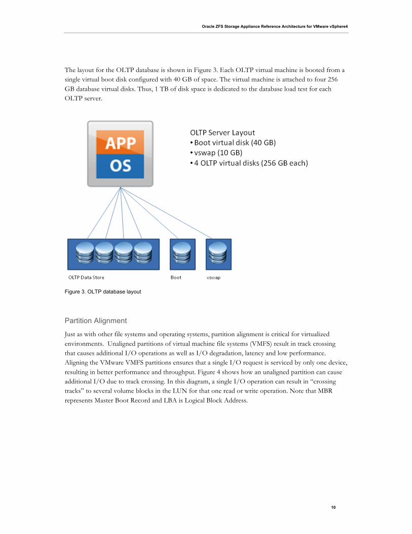
The layout for the OLTP database is shown in Figure 3. Each OLTP virtual machine is booted from a single virtual boot disk configured with 40 GB of space. The virtual machine is attached to four 256 GB database virtual disks. Thus, 1 TB of disk space is dedicated to the database load test for each OLTP server.
Figure 3. OLTP database layout
Partition Alignment
Just as with other file systems and operating systems, partition alignment is critical for virtualized environments. Unaligned partitions of virtual machine file systems (VMFS) result in track crossing that causes additional I/O operations as well as I/O degradation, latency and low performance. Aligning the VMware VMFS partitions ensures that a single I/O request is serviced by only one device, resulting in better performance and throughput. Figure 4 shows how an unaligned partition can cause additional I/O due to track crossing. In this diagram, a single I/O operation can result in “crossing tracks” to several volume blocks in the LUN for that one read or write operation. Note that MBR represents Master Boot Record and LBA is Logical Block Address.

Oracle ZFS Storage Appliance Reference Architecture for VMware vSphere4
11
Figure 4. VMware unaligned partition layout
The following figure shows an aligned partition. In this scenario, a single read or write is serviced by only one device, resulting in better throughput and reduced latency.
Figure 5. VMware aligned partition layout

Oracle ZFS Storage Appliance Reference Architecture for VMware vSphere4
12
Consider the following recommendations and best practices for partition alignment when working with VMware vSphere4 and Oracle ZFS Storage Appliance:
• Align the VMFS partitions with 64KB track boundaries. Because the VMware vSphere client automatically aligns the VMFS partitions along the 64KB boundary, it is a good option to use the vSphere client to create your VMFS partition table.
• You can apply the VMFS partition alignment recommendations to both block and IP-based storage solutions and to Fibre Channel, iSCSI and NFS protocols.
• Align VMFS partitions on the physical servers (ESX 4.1 Hypervisors) and also the data file systems partition within the virtual machines.
• Alignment of virtual machines boot disks is not required; align only the data disks.
• For aligning partitions in Linux guest file systems, use the fdisk utility. The default value for the partition start is 63, which means the partition is not aligned. Running fdisk – lu ensures that the partition starts at 128.
• For aligning partitions in Windows guest file systems, use the diskpart utility.
• Utilizing the VMware VCenter Converter tool can automate physical-to-virtual (P2V) and virtual-to-virtual (V2V) migrations as well as conversions between different virtual machines formats. Also, this tool can be used for optimizing partition alignment of virtual machines. Refer to VMware’s documentation web site for additional information.
Application Performance Validation
Next, an application workload was applied to the system to verify that the system as configured could deliver the needed performance in terms of I/O operations, latency, and bandwidth. Application workloads included a Microsoft Exchange mail system, an OLTP database, and a DSS database.
For each application, the application virtual disks were modified to be aligned on a 64-block offset. This ensures the most efficient use of I/O in the configuration. The Exchange database and log virtual disks, as well as all disks used for the OLTP and DSS databases, were aligned using either the Microsoft diskpart or the Linux fdisk utility.
Using the Oracle ZFS Storage Appliance DTrace Analytics tool, the administrator can see exactly how the various applications’ workloads – in these examples, the Microsoft Exchange mail system, an OLTP database, and DSS database -- are behaving down to the virtual disk level.
Microsoft Exchange Server Jetstress Validation
Two Microsoft Exchange mail servers were configured with a total of 6000 mail users. Each user’s mailbox held 250 MB of data for a total of 1.5 TB of mail data under test. The workload profile was 0.5 IOPs per user which corresponds to a “heavy” email user according to Microsoft guidelines.

Oracle ZFS Storage Appliance Reference Architecture for VMware vSphere4
13
TABLE 6. MICROSOFT EXCHANGE SERVER JETSTRESS PERFORMANCE RESULTS
METRIC RESULT
IOPs Achieved 3080 IOPs
Avg. DB Read Latency (target < 20ms) 14.79 ms
Avg. Log Write Latency (target < 10ms) 1.78 ms
Figure 6 shows the number of NFS operations per virtual disk in the mail system.
Figure 6. DTrace Analytics showing NFS operations per second for each virtual disk in the mail system
Figure 7 shows the number of NFS operations per section broken down into read operations and write operations.
Figure 7. DTrace Analytics showing the number of NFS read and write operations for mail servers
These results validate that this configuration can support 6,000 MS Exchange users using 44 mirrored data disks for the Exchange database files and 18 mirrored data disks for the Exchange log files.
OLTP Database Validation
Two Oracle Linux virtual machines were configured with the ORION benchmark tool to simulate an OLTP database workload against a total of eight virtual disks. The capacity of each virtual disk was 256, resulting in a total size of 2 TB for the databases under test.

Oracle ZFS Storage Appliance Reference Architecture for VMware vSphere4
14
TABLE 7. ORION OLTP PERFORMACE RESULTS
PARAMETER VALUE
Block size 8KB
RAID level Mirror
Write/read ratio 60/40
Number of outstanding I/Os per virtual
machine
64
Total IOPs achieved 11,887
Average latency 10.8ms
Figure 8 shows the number of NFS operations per second for each database virtual disk.
Figure 8. DTrace Analytics showing the number of NFS operations per second for the OLTP database virtual disks
Figure 9 shows the number of NFS operations per second broken down into read operations and write operations.
Figure 9. DTrace Analytics showing the number of NFS read and write operations for the OTLP databases
These results validate that this configuration can sustain a large number of I/Os typical of an OLTP database, while maintaining acceptable service levels using 44 mirrored data disks.

Oracle ZFS Storage Appliance Reference Architecture for VMware vSphere4
15
DSS Database Validation
Two Oracle Linux virtual machines were configured with the ORION benchmark tool to simulate a DSS database workload against a total of eight virtual disks. The capacity of each virtual disk was 256 GB, resulting in a total size of 2 TB for the databases under test. The object of this test was to demonstrate sustained bandwidth throughput for sequential reads of large data blocks.
TABLE 8. ORION DSS PERFORMANCE RESULTS
PARAMETER VALUE
Block Size 1024KB
RAID Level Mirror
Write/Read Ratio 0/100
Number of Outstanding I/Os per Virtual
Machine
24
Total Throughput 100 % Cache Hit – 645 MB/s
60% Cache Hit – 277 MB/s
<40% Cache Hit – 133 MB/s
Figure 10 shows the NFS operations per second for the DSS database virtual disks.
Figure 10. DTrace Analytics showing the number of NFS operations per second for the DSS database virtual disks

Oracle ZFS Storage Appliance Reference Architecture for VMware vSphere4
16
Figure 11 shows the network interface throughput in bytes per second.
Figure 11. DTrace Analytics showing the network interface throughput
Conclusion
The reference architecture described in this paper comprises an Oracle ZFS Storage Appliance and VMware vSphere configuration that can be deployed for highly demanding IT application workloads. Mixed application workloads can be consolidated on a robust and flexible Oracle ZFS Storage platform to improve performance, increase operational visibility, and reduce management costs.
This configuration was validated to deliver the performance needed for three applications: a Microsoft Exchange mail system, an OLTP database, and a DSS database, with workloads distributed across multiple operating systems and application workload profiles. No degradation in performance was seen while running all applications and workloads simultaneously.
The use of LJZB compression on the Oracle ZFS Storage Appliance in conjunction with thin provisioning resulted in significant space savings and efficiencies.
Oracle ZFS Storage Appliance Reference Architecture for VMware vSphere4.1 December 2013, Version 1.2 Author: Ryan Arneson Contributing Author: Anderson Souza Oracle Corporation World Headquarters 500 Oracle Parkway Redwood Shores, CA 94065 U.S.A.
Worldwide Inquiries: Phone: +1.650.506.7000 Fax: +1.650.506.7200
oracle.com
Copyright © 2013, Oracle and/or its affiliates. All rights reserved. This document is provided for information purposes only and the contents hereof are subject to change without notice. This document is not warranted to be error-free, nor subject to any other warranties or conditions, whether expressed orally or implied in law, including implied warranties and conditions of merchantability or fitness for a particular purpose. We specifically disclaim any liability with respect to this document and no contractual obligations are formed either directly or indirectly by this document. This document may not be reproduced or transmitted in any form or by any means, electronic or mechanical, for any purpose, without our prior written permission.
Oracle and Java are registered trademarks of Oracle and/or its affiliates. Other names may be trademarks of their respective owners.
AMD, Opteron, the AMD logo, and the AMD Opteron logo are trademarks or registered trademarks of Advanced Micro Devices. Intel and Intel Xeon are trademarks or registered trademarks of Intel Corporation. All SPARC trademarks are used under license and are trademarks or registered trademarks of SPARC International, Inc. UNIX is a registered trademark licensed through X/Open Company, Ltd. 1010