newsletter - enginsoft - home · using acp and ls-dyna ... ansys, ansys workbench, autodyn, cfx,...
TRANSCRIPT

010100101110101001110101100101001101110010100101010100101110101001110101100101001
101110
01
0100101001010010
1010
10010111011001
011 Newsletter
Simulation Based Engineering & SciencesYear n°2 Summer 201411
Interview with the Tuscany District President of Railway Technology
Saipem’s further innovation in Urea Technology
HPE: Passion for engines and a great push towards innovation
A modeFRONTIER case study about the optimization of the windshield structure
CFD analysis of a lube oil tank: air ingestion investigation
EnginSoft and Brembana&Rolle: key partner for the design of a steam super heat exchanger
CO2 Stripping Column EffluentSystem Application employing Saipem
mechanical innovative Technology
CAEPOSTER AWARD
27
October
2014
INTERNATIONAL
The International CAE Conference 2014 will take place on the 27th-28th October in Turin, Italy. For the third year in a row, EnginSoft are once again the official sponsors of the CAE Poster Award.
A competition dedicated to case studies, highlighting the latest innovative CAE applications. The CAE Poster Award invites students, graduates, researchers and professors, from both universities and research centres, to submit posters to demonstration their CAE excellence.
The best 5 posters will be awarded with a Smart Watch courtesy of EnginSoft.
Sponsored by
www.caeconference.comFor more information, please visit:
3 - Newsletter EnginSoft Year 11 n°2 Flash
LASHI am pleased to welcome you to our second Newsletter of 2014. I am sure that you will agree with me that its rich variety of articles provides interesting material for any engineer – and has prompted in my mind some reflections on the phrase “genius”.I recently had the pleasure of standing once again before Florence’s famous cathedral, and observing its magnificent cupola, designed and implemented at the dawn of the renaissance. If you are not aware of this awe-inspiring structure, it remains the largest masonry dome ever built – over 41 meters in diameter, of octagonal plan with a soaring elegance rising to 115 meters above pavement level. The creation of this masterpiece can truly be described as a work of genius – its design was revolutionary, it was self-supporting throughout its construction (requiring no centring), ingeniously contained its lateral stresses to obviate the need for buttressing, and required many innovations in building equipment and techniques.All these solutions appear to have been derived in the mind of one man, its principal architect Brunelleschi, and are all the more noteworthy because they were largely unprecedented. Knowing a little of its technical background greatly enhances its aesthetic appeal, and we can easily applaud it as the work of an extraordinary engineer, craftsman and artist working at a pivotal point in European history.However, despite the appreciation we can have such a product of individual genius, in many ways it is alien to the practise of engineering that we see exemplified in the articles of our Newsletter. Here, over and above the diversity of topics, we note as well the diversity of participants – these capabilities arise from multidisciplinary teams, typically from several organisations, bringing their expertise together in innovative ways.This is well-illustrated by the example of SAIPEM, a company with which we have a long history of partnership in several disciplines and across different sites. In recent times, for example, our engineers have collaborated to develop an innovative means of towing and laying marine pipelines in shallow water, and this month you can read about our partnership in the design of two effluent piping systems for use in Ammonia Plants. I am proud of EnginSoft’s ability to integrate our skills with those of Saipem to produce novel solutions – and inspired once again by the many other stories of collaborative creativity described in our Newsletter.The methods are elegant, and use the high intellectual capital of EnginSoft or our partners; but if they can be described as genius then it is not the individual and solitary act of creation that we celebrate, but the ability of networks within and between organisations to deliver creativity from fruitful cooperation.
Stefano Odorizzi, Editor in chief
F
Contents
Contents
Newsletter EnginSoft Year 11 n°2 - 4
INTERVIEW6 Interview with the President of the DITECFER the District of the Railways Technology of Tuscany
SUCCESS STORIES8 Passion for engines and a great push towards innovation9 Ball Valves: the Experience of DAFRAM
CASE HISTORIES12 CO2 Stripping Column Effluent System Application employing Saipem mechanical innovative Technology23 The SuperCups Trays – Saipem’s further innovation in Urea Technology27 CFD analysis of a lube oil tank: air ingestion investigation30 EnginSoft and Brembana&Rolle: key partner for the design of a steam super heater exchanger33 A modeFRONTIER case study about the optimization of the windshield structure37 Simulation of icing and de-icing, using Computational Fluid Dynamics40 Innovative approach to calculate lamination curves in ring rolling operations through simulation44 A new methodology based on LS-DYNA for integrating product & process engineering of a steel wheel47 A multiphase model for prediction of tumor growth: a step towards drug delivery simulation
51 Recent Advances and Problems in Seismic Simulation of Nuclear Power Plants
SOFTWARE UPDATE55 RBF Morph software – how to reshape the CAE workflow by Radial Basis Functions mesh morphing58 FEM analysis of composite material using ACP and LS-DYNA61 Optimizing ECUs at Alma Automotive63 Material Properties Database
RESEARCH64 Optimizing the integration of a chemical process with a concentrated solar power source: the SOL2HY2 project66 Educational EU programme: EnginSoft involvementIN
CORPORATE NEWS68 EnginSoft is full member of ETP4HPC, the European Platform for HPC69 EnginSoft testimonial of a success in the US market
5 - Newsletter EnginSoft Year 11 n°2
OUR ACKNOWLEDGEMENT AND THANKS TO ALL THE COMPANIES, UNIVERSITIES AND RESEARCH CENTRES THAT HAVE CONTRIBUTED TO THIS ISSUE OF OUR NEWSLETTER
Contents
Newsletter EnginSoftYear 11 n°2 - Summer 2014To receive a free copy of the next EnginSoft Newsletters, please contact our Marketing office at: [email protected]
All pictures are protected by copyright. Any reproduction of these pictures in any media and by any means is forbidden unless written authorization by EnginSoft has been obtained beforehand. ©Copyright EnginSoft Newsletter.
EnginSoft S.p.A.24126 BERGAMO c/o Parco Scientifico TecnologicoKilometro Rosso - Edificio A1, Via Stezzano 87Tel. +39 035 368711 • Fax +39 0461 97921550127 FIRENZE Via Panciatichi, 40Tel. +39 055 4376113 • Fax +39 0461 97921635129 PADOVA Via Giambellino, 7Tel. +39 049 7705311 • Fax +39 0461 97921772023 MESAGNE (BRINDISI) Via A. Murri, 2 - Z.I.Tel. +39 0831 730194 • Fax +39 0461 97922438123 TRENTO fraz. Mattarello - Via della Stazione, 27Tel. +39 0461 915391 • Fax +39 0461 97920110133 TORINO Corso Moncalieri, 223Tel. +39 011 3473987 • Fax +39 011 3473987
www.enginsoft.it - www.enginsoft.come-mail: [email protected]
The EnginSoft NEWSLETTER is a quarterly magazine published by EnginSoft SpA
COMPANY INTERESTSCONSORZIO TCN www.consorziotcn.it • www.improve.it
EnginSoft GmbH - GermanyEnginSoft UK - United KingdomEnginSoft France - FranceEnginSoft Nordic - Swedenwww.enginsoft.com
Cascade Technologies www.cascadetechnologies.comReactive Search www.reactive-search.comSimNumerica www.simnumerica.itM3E Mathematical Methods and Models for Engineering www.m3eweb.it
ASSOCIATION INTERESTSNAFEMS International www.nafems.it • www.nafems.orgTechNet Alliance www.technet-alliance.com
AdvertisementFor advertising opportunities, please contact our Marketing office at: [email protected]
RESPONSIBLE DIRECTORStefano Odorizzi - [email protected]
ART DIRECTORLuisa Cunico - [email protected]
PRINTING Grafiche Dal Piaz - Trento
Auto
rizza
zione
del
Trib
unal
e di
Tre
nto
n° 1
353
RS d
i dat
a 2/
4/20
08
The EnginSoft Newsletter editions contain references to the following products which are trademarks or registered trademarks of their respective owners: ANSYS, ANSYS Workbench, AUTODYN, CFX, FLUENT and any and all ANSYS, Inc. brand, product, service and feature names, logos and slogans are registered trademarks or trademarks of ANSYS, Inc. or its subsidiaries in the United States or other countries. [ICEM CFD is a trademark used by ANSYS, Inc. under license]. (www.ansys.com) modeFRONTIER is a trademark of ESTECO Spa (www.esteco.com) Flowmaster is a registered trademark of Mentor Graphics in the USA (www.flowmaster.com) MAGMASOFT is a trademark of MAGMA GmbH (www.magmasoft.de) FORGE and COLDFORM are trademarks of Transvalor S.A. (www.transvalor.com) FENSAP-ICE is a trademark of NTI Newmerical (www.newmerical.com) LS-DYNA ia a trademark of LSTC (www.lstc.com) TOTAL MATERIA is a trademark of Key to Metals AG (www.keytometals.com)
Interview Newsletter EnginSoft Year 11 n°2 - 6
EnginSoft, one of the leading companies in Italy that develops and produces goods and services for all industrial sectors related to transportation, is one of the founders of the brand-new “Italy Transportation Cluster 2020”. This initiative, whose formal constitution was signed last April 10th, at ANFIA in Rome, aims at fostering the competitiveness of the Italian companies in all the different subsectors of this important industry.As far as the rail system is concerned, EnginSoft is also an active member of the Tuscany Cluster, gathering a pool of companies playing a relevant role in both national and international market, thanks to their quality, technologies and innovative concepts.The EnginSoft newsletter editing board interviewed its president, Eng. Lorenza Franzino.
1. Huge investments have been planned for the next years to develop the European transportation network, a context which lies behind the creation of the “Italy Transportation Cluster 2020”. Considering the complexity of the cluster, with many different actors dealing with various transportation sectors (automotive, naval and rail industry), what are the particularly interesting issues for the rail sector, according to your opinion?
The white paper of the European Commission Roadmap to a Single European Transport Area - Towards a competitive and resource efficient transport system” of 2011 states that the transportation system has become a central element in modern economies.The creation of modern mobility system, environmentally-friendly and sustainable from an economic and social point of view, is the key goal to be pursued. In such a context, the rail system is increasingly relevant in meeting society’s mobility expectations and needs, such as accessibility, and the integration of cities and
metropolitan areas. It is highly preferable to work towards the large-scale integration capabilities of the transportation network, combining rail, subways, trams, people movers and other constrained guidance transport systems.
Therefore, it is a strategic decision for the European Union and the Italian Government to face such mobility issues in an integrated way, challenging the different transportation sectors to create synergies able, not just to support intermodal transport but also to foster a common Research and Development policy. The rail sector has to play a strategic role in the Europe roadmap planned for 2030/2050, considering the market trend of the sector as annually analysed by UNIFE.
2. Which are your expectations, in terms of results coming from a tight collaboration with Industry, Research Institutes and Public Administration, as to the best practices, technological transfer and the high level training of the involved actors?
The rail mobility market requires a partnership between the public and the private sectors. Such a partnership, for both Industry and Academia, has to evolve and to look for more tangible, efficient and effective solutions to mobility problems and needs.
Interview with the President of the DITECFERthe District of the Railways Technology of Tuscany
Interview7 - Newsletter EnginSoft Year 11 n°2
The combination of competencies, expertise and experiences of each partner can lead to beneficial solutions for both the public and private sector. This could be improved by investing and sharing best practices, technology porting and skill upgrades, thus generating a global improvement of product and service quality whilst reducing time to market; summarizing, to become competitive!
3. In Italy other clusters are operating on a local level, such as two in Piemonte, one in Lombardia and other in the Lazio region. What relationships link these clusters? Is it possible to talk about an Italian system that shares goals on a global market?
I will take the opportunity provided by this question to provide a better explanation of the purposes of Tuscany District in comparison with the others that you mention. On the one hand, there are the so-called “Productive Districts” – the ones that you mention - which are very important organisms, mainly born and grown in connection with industrial or academic personalities, but not supported by the creation of “Technological Districts” by Regional Administrations. On the other hand, therefore, there are the “Industrial Districts”, which are the real core of the Italian business in many sectors.Just leaving terminology aside, the substantial difference between a Technological District such as ours, comparable only to DATTILO (Campania Districts for High Technology in Transportation System), and a “Productive District”, is that the regional administrations have fostered the innovation process of the local enterprises, strengthening the collaboration with Universities and Research Centres. The purpose is to combine the vision and inspiration coming from Academia with the knowledge of the market provided by companies. We strongly believe in this mixture and the goal of gathering 110 companies in our District can be a great incentive to identify possible collaborations with the other Productive Districts, such as Piemonte, Lombardia and Lazio region, to encourage a mutual growth.
4. The Tuscany District slogan is “Think Rail Think Tuscany”. Which are the peculiarities that differentiate it from the national technological offer?
The experience and resources devoted to the rail sector in Tuscany have a long history, marking our railways as one of our main assets.This history, however, is not enough; Tuscany presents itself to the national and international market as a “complete system of expertise”, including the several companies involved in the sector and the main four Academic bodies related to them – the University of Florence for carriage material, the University of Pisa for electronics, the Sant’Anna School and CNR in Pisa for the intelligent systems- also taking advantage of the Osmannoro Centre of Italcertifer that, with its Experimental Dynamics Centre, characterized by the largest semianechoic room in Europe: taken together, these contributions demonstrate the great investment of Tuscany in the rail sector. Last but not least, we observe that it is not by chance that the National Agency for Rail Security (ANSF) is located in Florence!
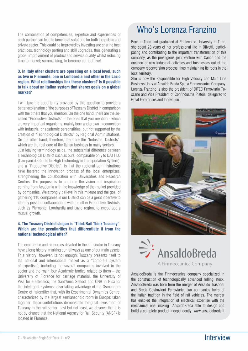
Who’s Lorenza FranzinoBorn in Turin and graduated at Politecnico University in Turin, she spent 23 years of her professional life in Olivetti, partici-pating and contributing to the important transformation of this company, as the prestigious joint venture with Canon and the creation of new industrial activities and businesses out of the company reconversion process, thus maintaining its roots in the local territory.She is now the Responsible for High Velocity and Main Line Business Unity at Ansaldo Breda Spa, a Finmeccanica Company. Lorenza Franzino is also the president of DITEC Ferroviario To-scano and Vice President of Confindustria Pistoia, delegated to Great Enterprises and Innovation.
AnsaldoBreda is the Finmeccanica company specialized in the construction of technologically advanced rolling stock. AnsaldoBreda was born from the merger of Ansaldo Trasporti and Breda Costruzioni Ferroviarie, two companies heirs of the Italian tradition in the field of rail vehicles. The merger has enabled the integration of electrical expertise with the mechanical one, making AnsaldoBreda able to design and build a complete product independently. www.ansaldobreda.it
Success Stories Newsletter EnginSoft Year 11 n°2 - 8
From Formula1 racing to aerospace and top-class industrial automation. Hpe activities, in collaboration with Coxa, are the feather in motor valley mechanics’ cap, investing as many resources as possible to train new generation experts.During 2010 Hpe, founded at the beginning of the new millennium by Piero Ferrari, decided to acquire Coxa, a company with over 20 years’ experience in high-precision mechanic manufacturing.Hpe-Coxa, specialized in design and production in highly technological sectors, can now boast a constantly growing turnover, that reached 21 million Euros in 2013, whose 30% obtained on international markets (Sweden, Germany and the United States). The work-force is constituted by 145 employees, 60% engineers, 30% specialized workers and 10% staff.In relation to the automotive sector (in which “motorsport” represents a 30% of the total activities), Hpe-Coxa works with customers like Ferrari, CNH, Harley Davidson, Maserati, EADS, Ducati and Piaggio, being also the reference partner for Finmeccanica (Ministry of Defense) and, as far as the automatic machines is concerned, for Tetrapak and GD.
“We offer niche technology from design to production” states Andrea Bozzoli, General Manager. “We take care of every single detail, from the design of the prototyped engines for Formula 1 to the production of precision mechanic components for aerospace”. “Considering the quality of the product, our niche activity is oriented to the most advanced markets”, Ing. Ferrari explains, “Our business lines are high engineering, design & production of automatic machines, prototypes creation for both Formula 1 racing and motorsport. Being one step forward our competitors is the most challenging target we have and the crisis has made us even more passionate.”
CAE driven product development: how ANSYS and modeFRONTIER speed up the design processHPE S.r.l. has introduced ANSYS and modeFRONTIER softwares in its own activities since 2006. Being usable over a wide range of application fields, such softwares fit very well the wide virtual prototyping requirements needed by HPE, according to the numerical tools have to be used for structural, fluid-dynamics, process & manufacturing analyses purposes. Further, the integration of ANSYS, and all other tool typically used by HPE, in modeFRONTIER platform allowed to maximise the efficiency of numerical approach, both in terms of full exploitation of software/hardware resources (no CPU time is wasted since modeFRONTIER works in background modality), and in terms of capability to
Passion for engines and a great push towards innovation
Success Stories9 - Newsletter EnginSoft Year 11 n°2
understand how the investigated phenomena behave and then to pursue the best performances. So far several applications have been performed by using ANSYS and modeFRONTIER technologies. The first remarkable one was a simulation of a Sodium cooled exhaust valve. The core was a FE thermal analysis model on ANSYS, quite simple by itself, but the environmental set, including fluid dynamics data from one-dimensional CFD, a second ANSYS thermal analysis model and several EXCEL sheets for pre and post processing, was rather complex. Linking the whole bundle was possible thanks to modeFRONTIER, which granted the correct workflow and allowed a quick solution in few iterations.
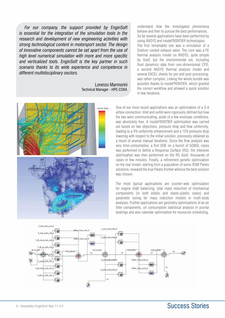
One of our most recent applications was an optimization of a 3-d airbox connection. Inlet and outlet were rigorously defined but how the two were communicating, aside of a few envelope conditions, was absolutely free. A modeFRONTIER optimization was carried out based on two objectives, pressure drop and flow uniformity, leading to a 4% uniformity enhancement and a 15% pressure drop lowering with respect to the initial solution, previously obtained as a result of several manual iterations. Since the flow analysis was very time-consumptive, a first DOE on a bunch of SOBOL cases was performed to define a Response Surface (RS): the intensive optimization was then performed on the RS itself, thousands of cases in few minutes. Finally, a refinement genetic optimization on the real model, starting from a population of some RSM Pareto solutions, revealed the true Pareto frontier whence the best solution was chosen.
The most typical applications are counter-web optimization for engine shaft balancing, total mass reduction of mechanical components (in both elastic and elasto-plastic cases) and parameter tuning for mass reduction models in multi-body analyses. Further applications are geometry optimizations of an air filter components, oil consumption statistical analysis in journal bearings and also calendar optimization for resources scheduling.
For our company, the support provided by EnginSoft is essential for the integration of the simulation tools in the research and development of new engineering activities with strong technological content in motorsport sector. The design of innovative components cannot be set apart from the use of high level numerical simulation with more and more specific and verticalized tools. EnginSoft is the key partner in such scenario thanks to its wide experience and competence in different multidisciplinary sectors.
Lorenzo MarmoriniTechnical Manager - HPE-COXA
Success Stories Newsletter EnginSoft Year 11 n°2 - 10
DAFRAM S.p.A., founded in 1956, was the first company to manufacture floating ball valves in Italy. The long experience gathered during more than 50 years of activity, looking for innovative solutions, ensures DAFRAM is one of the world’s most famous and competitive companies in the Oil and Gas sector.DAFRAM’s factory is located in Urbisaglia (Macerata) in the centre of Italy in an industrial complex covering 32000 square meters, 12000 of which are covered workshops. The factory consists of commercial, technical and engineering offices and of two extremely modern workshops, the latest of which (completed in February 2008) is 4200 square meters and 10 meters high, allowing the production, assembly, testing, sandblasting and painting of ball valves up to extremely large sizes and weights.The DAFRAM design and production staff includes highly qualified engineers with a long experience in all technical standards and in meeting customers’ special requirements. Modern design methods are employed to analyse specific stresses and deformation limits of valve bodies and main valve components.The manufacturing process is continuously improved and changed using the most advanced manufacturing technologies such as multi-function machining centres and computer-controlled lathes and automated welding equipment. Special testing centres are used for testing all products and are specifically used for high pressure and large size trunnion-mounted valves.In recent years ball valves have experienced a growing utilisation in Oil and Gas plants, thanks to a continuous improvement in terms of reliability and performance. Whilst project requirements have
become more challenging in respect of temperature, pressure and corrosive fluids, improved construction approaches have been developed which have allowed the ball valve to become the ideal solution to cope with flow interception and regulation, including that of polyphase fluids.In this context, design and prototyping activities are essential to the effective verification and virtual testing of the designed valve in relation to the real process conditions, considering pressure, temperature and interaction with other plant devices and equipment (actuators, pipes and supports).Another important requirement is the ability to consider the valve or the whole valve-actuator system under the particular limit
Ball Valves: the Experience of DAFRAM
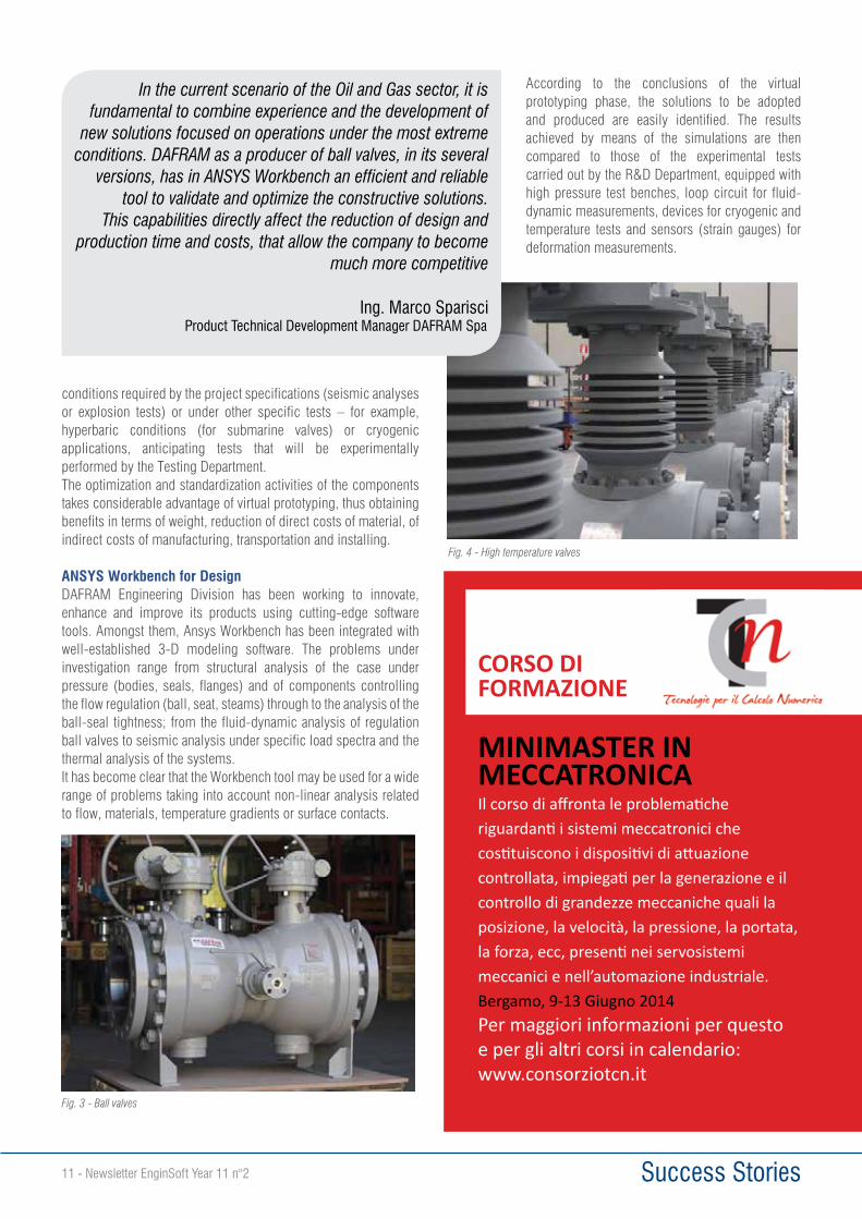
Fig. 1 - Strain calculated at shell test on the top-entry valve body Fig. 2 - Analysis of the ball-seat tightness for a soft insert
Success Stories11 - Newsletter EnginSoft Year 11 n°2
conditions required by the project specifications (seismic analyses or explosion tests) or under other specific tests – for example, hyperbaric conditions (for submarine valves) or cryogenic applications, anticipating tests that will be experimentally performed by the Testing Department. The optimization and standardization activities of the components takes considerable advantage of virtual prototyping, thus obtaining benefits in terms of weight, reduction of direct costs of material, of indirect costs of manufacturing, transportation and installing.
ANSYS Workbench for DesignDAFRAM Engineering Division has been working to innovate, enhance and improve its products using cutting-edge software tools. Amongst them, Ansys Workbench has been integrated with well-established 3-D modeling software. The problems under investigation range from structural analysis of the case under pressure (bodies, seals, flanges) and of components controlling the flow regulation (ball, seat, steams) through to the analysis of the ball-seal tightness; from the fluid-dynamic analysis of regulation ball valves to seismic analysis under specific load spectra and the thermal analysis of the systems.It has become clear that the Workbench tool may be used for a wide range of problems taking into account non-linear analysis related to flow, materials, temperature gradients or surface contacts.
According to the conclusions of the virtual prototyping phase, the solutions to be adopted and produced are easily identified. The results achieved by means of the simulations are then compared to those of the experimental tests carried out by the R&D Department, equipped with high pressure test benches, loop circuit for fluid-dynamic measurements, devices for cryogenic and temperature tests and sensors (strain gauges) for deformation measurements.
MINIMASTER IN MECCATRONICAIl corso di affronta le problematiche riguardanti i sistemi meccatronici che costituiscono i dispositivi di attuazione controllata, impiegati per la generazione e il controllo di grandezze meccaniche quali la posizione, la velocità, la pressione, la portata, la forza, ecc, presenti nei servosistemi meccanici e nell’automazione industriale.Bergamo, 9-13 Giugno 2014Per maggiori informazioni per questo e per gli altri corsi in calendario:www.consorziotcn.it
CORSO DI FORMAZIONE
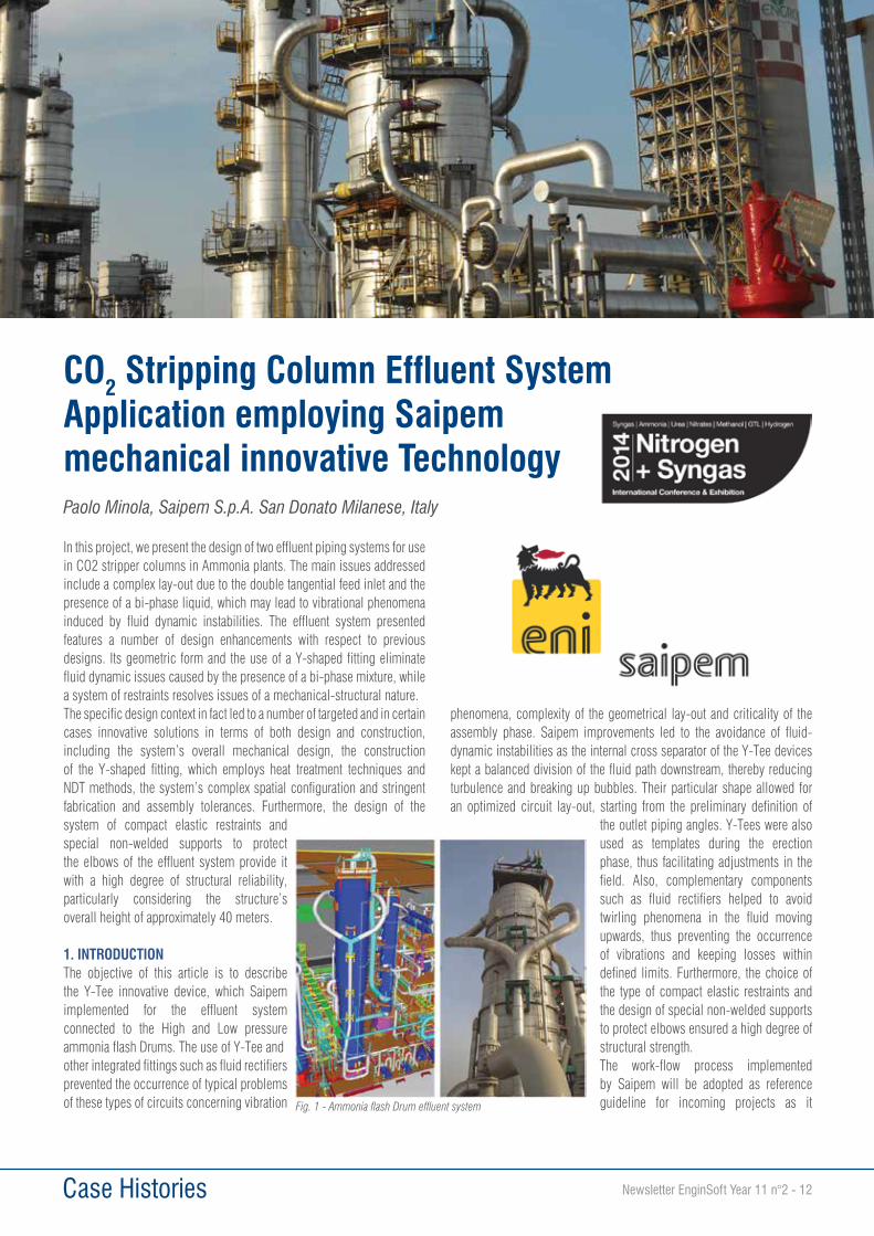
Fig. 3 - Ball valves
Fig. 4 - High temperature valves
In the current scenario of the Oil and Gas sector, it is fundamental to combine experience and the development of
new solutions focused on operations under the most extreme conditions. DAFRAM as a producer of ball valves, in its several
versions, has in ANSYS Workbench an efficient and reliable tool to validate and optimize the constructive solutions.
This capabilities directly affect the reduction of design and production time and costs, that allow the company to become
much more competitive
Ing. Marco Sparisci Product Technical Development Manager DAFRAM Spa
Case Histories Newsletter EnginSoft Year 11 n°2 - 12
CO2 Stripping Column Effluent System Application employing Saipem mechanical innovative Technology
In this project, we present the design of two effluent piping systems for use in CO2 stripper columns in Ammonia plants. The main issues addressed include a complex lay-out due to the double tangential feed inlet and the presence of a bi-phase liquid, which may lead to vibrational phenomena induced by fluid dynamic instabilities. The effluent system presented features a number of design enhancements with respect to previous designs. Its geometric form and the use of a Y-shaped fitting eliminate fluid dynamic issues caused by the presence of a bi-phase mixture, while a system of restraints resolves issues of a mechanical-structural nature.The specific design context in fact led to a number of targeted and in certain cases innovative solutions in terms of both design and construction, including the system’s overall mechanical design, the construction of the Y-shaped fitting, which employs heat treatment techniques and NDT methods, the system’s complex spatial configuration and stringent fabrication and assembly tolerances. Furthermore, the design of the system of compact elastic restraints and special non-welded supports to protect the elbows of the effluent system provide it with a high degree of structural reliability, particularly considering the structure’s overall height of approximately 40 meters.
1. INTRODUCTIONThe objective of this article is to describe the Y-Tee innovative device, which Saipem implemented for the effluent system connected to the High and Low pressure ammonia flash Drums. The use of Y-Tee andother integrated fittings such as fluid rectifiers prevented the occurrence of typical problems of these types of circuits concerning vibration
phenomena, complexity of the geometrical lay-out and criticality of the assembly phase. Saipem improvements led to the avoidance of fluid-dynamic instabilities as the internal cross separator of the Y-Tee devices kept a balanced division of the fluid path downstream, thereby reducing turbulence and breaking up bubbles. Their particular shape allowed for an optimized circuit lay-out, starting from the preliminary definition of
the outlet piping angles. Y-Tees were also used as templates during the erection phase, thus facilitating adjustments in the field. Also, complementary components such as fluid rectifiers helped to avoid twirling phenomena in the fluid moving upwards, thus preventing the occurrence of vibrations and keeping losses within defined limits. Furthermore, the choice of the type of compact elastic restraints and the design of special non-welded supports to protect elbows ensured a high degree of structural strength.The work-flow process implemented by Saipem will be adopted as reference guideline for incoming projects as it
Paolo Minola, Saipem S.p.A. San Donato Milanese, Italy
Fig. 1 - Ammonia flash Drum effluent system
Case Histories13 - Newsletter EnginSoft Year 11 n°2
integrated the fluid-dynamic and the mechanical aspects. The designed fittings constituted innovative technological solutions that enabled to gain a high level of plant reliability: positive expectations concerning the benefits gained by their insertion on ammonia-urea plants have been fully satisfied. Saipem accomplished this goal through a multidisciplinary approach made possible by the collaboration between specialists in the Saipem headquarters, on site and by a skilled team in the workshop. The team applied Saipem’s instructions step by step with respect to both the design and the construction aspects of the project.The entire design of the ammonia effluent lines was implemented in the following Ammonia-Urea plants that have been in operation for several years with no evidence of fluid-dynamic instabilities due to unbalanced forces:• ENGRO DAHARKI COMPLEX - Pakistan• QAFCO5 FERTILIZER COMPLEX – Qatar
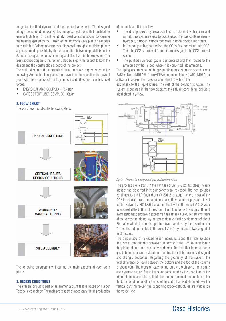
2. FLOW-CHARTThe work flow includes the following steps.
The following paragraphs will outline the main aspects of each work phase.
3. DESIGN CONDITIONSThe effluent circuit is part of an ammonia plant that is based on Haldor Topsøe’s technology. The main process steps necessary for the production
of ammonia are listed below:• The desulphurized hydrocarbon feed is reformed with steam and
air into raw synthesis gas (process gas). The gas contains mainly hydrogen, nitrogen, carbon monoxide, carbon dioxide and steam.
• In the gas purification section, the CO is first converted into CO2. Then the CO2 is removed from the process gas in the CO2 removal section.
• The purified synthesis gas is compressed and then routed to the ammonia synthesis loop, where it is converted into ammonia.
The piping system is part of the gas purification section and operates with BASF solvent aMDEA®. The aMDEA solution contains 40 wt% aMDEA; an activator increases the mass transfer rate of CO2 from thegas phase to the liquid phase. The rest of the solution is water. The system is outlined in the flow diagram: the effluent considered circuit is highlighted in yellow.
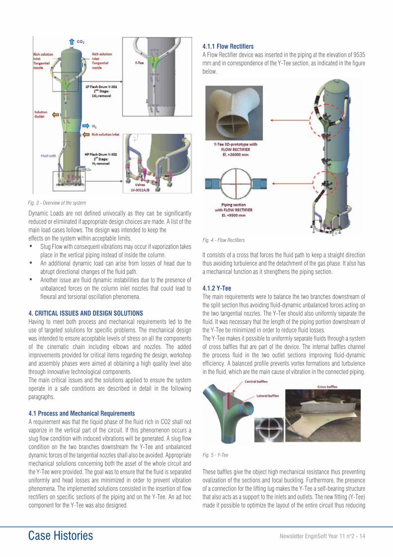
The process cycle starts in the HP flash drum (V-302, 1st stage), where most of the dissolved inert components are released. The rich solution continues to the LP flash drum (V-301,2nd stage), where most of the CO2 is released from the solution at a defined value of pressure. Level control valves LV-3011A/B that act on the level in the vessel V-302 were positioned at the bottom of the circuit. Their function is to ensure sufficient hydrostatic head and avoid excessive flash at the valve outlet. Downstream of the valves the piping lay-out presents a vertical development of about 20m after which the line is split into two branches by the insertion of a Y-Tee. The solution is fed to the vessel V-301 by means of two tangential inlet nozzles.The percentage of released vapor increases along the rich solution line. Small gas bubbles dissolved uniformly in the rich solution inside the piping should not cause any problems. On the other hand, as large gas bubbles can cause vibration, the circuit shall be properly designed and strongly supported. Regarding the geometry of the system, the total difference of level between the bottom and the top of the column is about 40m. The types of loads acting on the circuit are of both static and dynamic nature. Static loads are constituted by the dead load of the piping, fittings, and internal fluid plus the pressure and temperature of the fluid. It should be noted that most of the static load is distributed over the vertical part; moreover, the supporting bracket structures are welded on the Vessel shell.
Fig. 2 - Process flow diagram of gas purification section
Case Histories Newsletter EnginSoft Year 11 n°2 - 14
Dynamic Loads are not defined univocally as they can be significantly reduced or eliminated if appropriate design choices are made. A list of the main load cases follows. The design was intended to keep theeffects on the system within acceptable limits.• Slug Flow with consequent vibrations may occur if vaporization takes
place in the vertical piping instead of inside the column.• An additional dynamic load can arise from losses of head due to
abrupt directional changes of the fluid path.• Another issue are fluid dynamic instabilities due to the presence of
unbalanced forces on the column inlet nozzles that could lead to flexural and torsional oscillation phenomena.
4. CRITICAL ISSUES AND DESIGN SOLUTIONSHaving to meet both process and mechanical requirements led to the use of targeted solutions for specific problems. The mechanical design was intended to ensure acceptable levels of stress on all the components of the cinematic chain including elbows and nozzles. The added improvements provided for critical items regarding the design, workshop and assembly phases were aimed at obtaining a high quality level also through innovative technological components.The main critical issues and the solutions applied to ensure the system operate in a safe conditions are described in detail in the following paragraphs.
4.1 Process and Mechanical RequirementsA requirement was that the liquid phase of the fluid rich in CO2 shall not vaporize in the vertical part of the circuit. If this phenomenon occurs a slug flow condition with induced vibrations will be generated. A slug flow condition on the two branches downstream the Y-Tee and unbalanced dynamic forces of the tangential nozzles shall also be avoided. Appropriate mechanical solutions concerning both the asset of the whole circuit and the Y-Tee were provided. The goal was to ensure that the fluid is separated uniformly and head losses are minimized in order to prevent vibration phenomena. The implemented solutions consisted in the insertion of flow rectifiers on specific sections of the piping and on the Y-Tee. An ad hoc component for the Y-Tee was also designed.
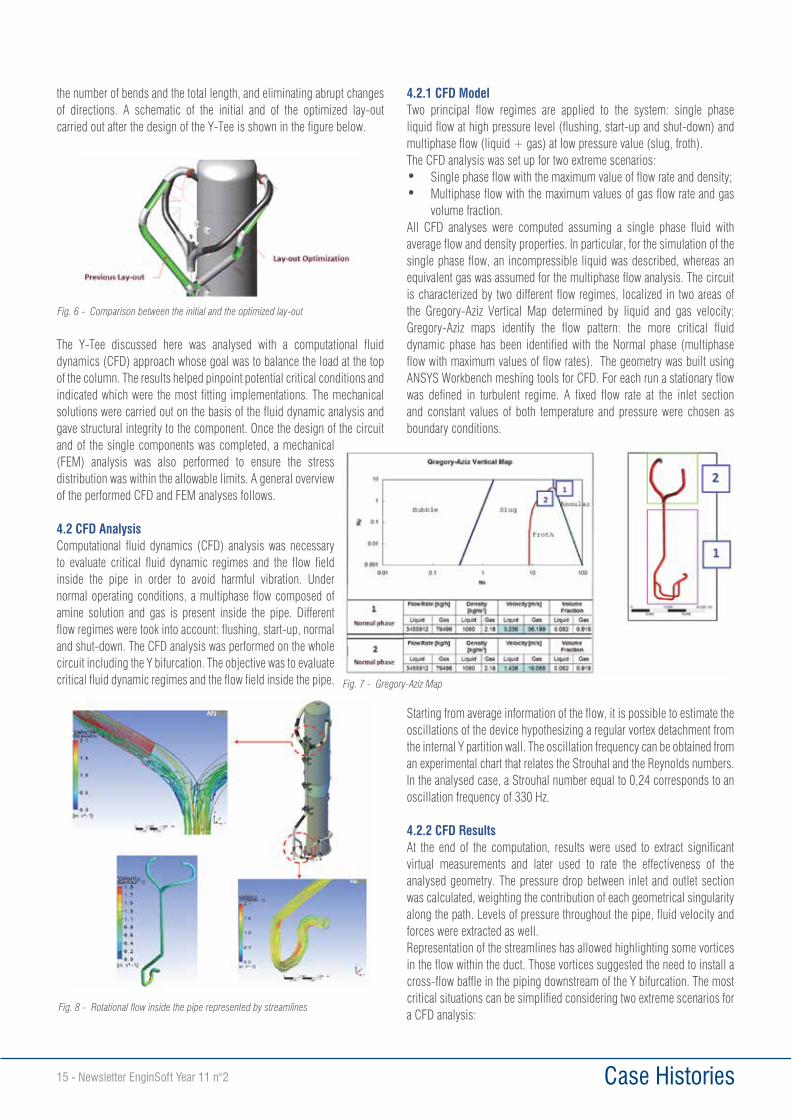
4.1.1 Flow RectifiersA Flow Rectifier device was inserted in the piping at the elevation of 9535 mm and in correspondence of the Y-Tee section, as indicated in the figure below.
It consists of a cross that forces the fluid path to keep a straight direction thus avoiding turbulence and the detachment of the gas phase. It also has a mechanical function as it strengthens the piping section.
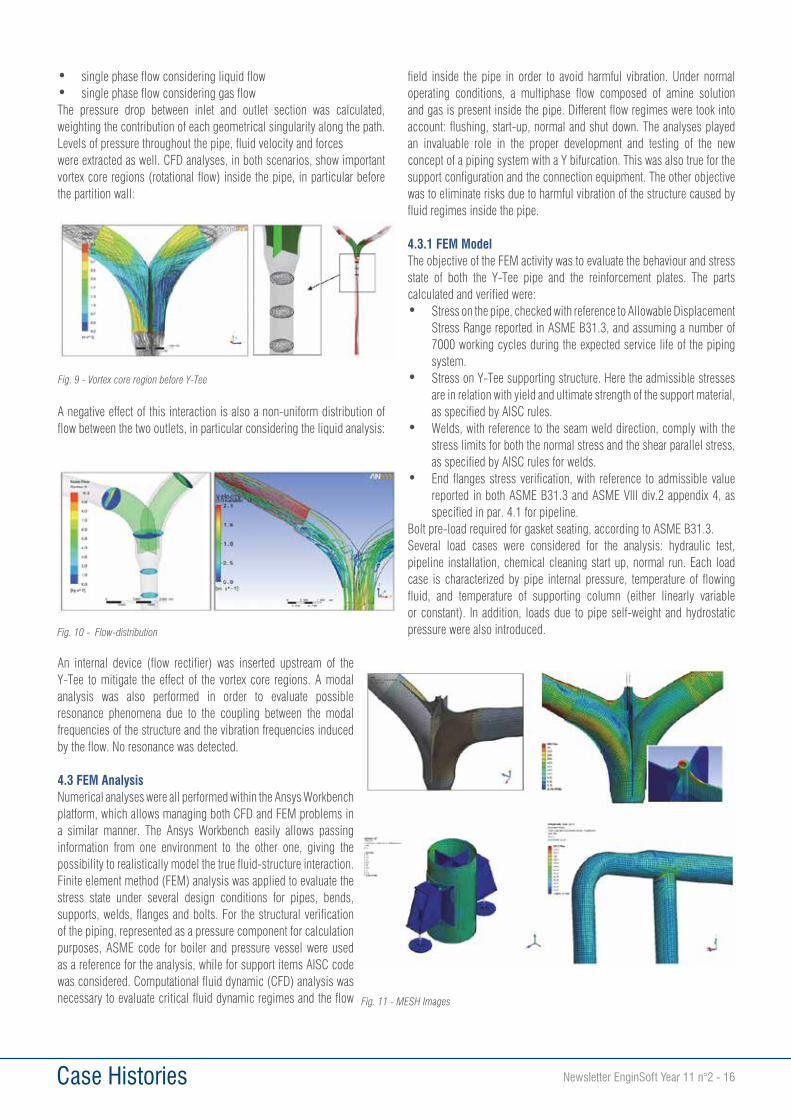
4.1.2 Y-TeeThe main requirements were to balance the two branches downstream of the split section thus avoiding fluid-dynamic unbalanced forces acting on the two tangential nozzles. The Y-Tee should also uniformly separate the fluid. It was necessary that the length of the piping portion downstream of the Y-Tee be minimized in order to reduce fluid losses.The Y-Tee makes it possible to uniformly separate fluids through a system of cross baffles that are part of the device. The internal baffles channel the process fluid in the two outlet sections improving fluid-dynamic efficiency. A balanced profile prevents vortex formations and turbulence in the fluid, which are the main cause of vibration in the connected piping.
These baffles give the object high mechanical resistance thus preventing ovalization of the sections and local buckling. Furthermore, the presence of a connection for the lifting lug makes the Y-Tee a self-bearing structure that also acts as a support to the inlets and outlets. The new fitting (Y-Tee) made it possible to optimize the layout of the entire circuit thus reducing
Fig. 3 - Overview of the system
Fig. 4 - Flow Rectifiers
Fig. 5 - Y-Tee
Case Histories15 - Newsletter EnginSoft Year 11 n°2
the number of bends and the total length, and eliminating abrupt changes of directions. A schematic of the initial and of the optimized lay-out carried out after the design of the Y-Tee is shown in the figure below.
The Y-Tee discussed here was analysed with a computational fluid dynamics (CFD) approach whose goal was to balance the load at the top of the column. The results helped pinpoint potential critical conditions and indicated which were the most fitting implementations. The mechanical solutions were carried out on the basis of the fluid dynamic analysis and gave structural integrity to the component. Once the design of the circuit and of the single components was completed, a mechanical (FEM) analysis was also performed to ensure the stress distribution was within the allowable limits. A general overview of the performed CFD and FEM analyses follows.
4.2 CFD AnalysisComputational fluid dynamics (CFD) analysis was necessary to evaluate critical fluid dynamic regimes and the flow field inside the pipe in order to avoid harmful vibration. Under normal operating conditions, a multiphase flow composed of amine solution and gas is present inside the pipe. Different flow regimes were took into account: flushing, start-up, normal and shut-down. The CFD analysis was performed on the whole circuit including the Y bifurcation. The objective was to evaluate critical fluid dynamic regimes and the flow field inside the pipe.
4.2.1 CFD ModelTwo principal flow regimes are applied to the system: single phase liquid flow at high pressure level (flushing, start-up and shut-down) and multiphase flow (liquid + gas) at low pressure value (slug, froth).The CFD analysis was set up for two extreme scenarios:• Single phase flow with the maximum value of flow rate and density;• Multiphase flow with the maximum values of gas flow rate and gas
volume fraction.All CFD analyses were computed assuming a single phase fluid with average flow and density properties. In particular, for the simulation of the single phase flow, an incompressible liquid was described, whereas an equivalent gas was assumed for the multiphase flow analysis. The circuit is characterized by two different flow regimes, localized in two areas of the Gregory-Aziz Vertical Map determined by liquid and gas velocity; Gregory-Aziz maps identify the flow pattern: the more critical fluid dynamic phase has been identified with the Normal phase (multiphase flow with maximum values of flow rates). The geometry was built using ANSYS Workbench meshing tools for CFD. For each run a stationary flow was defined in turbulent regime. A fixed flow rate at the inlet section and constant values of both temperature and pressure were chosen as boundary conditions.
Starting from average information of the flow, it is possible to estimate the oscillations of the device hypothesizing a regular vortex detachment from the internal Y partition wall. The oscillation frequency can be obtained from an experimental chart that relates the Strouhal and the Reynolds numbers. In the analysed case, a Strouhal number equal to 0,24 corresponds to an oscillation frequency of 330 Hz.
4.2.2 CFD ResultsAt the end of the computation, results were used to extract significant virtual measurements and later used to rate the effectiveness of the analysed geometry. The pressure drop between inlet and outlet section was calculated, weighting the contribution of each geometrical singularity along the path. Levels of pressure throughout the pipe, fluid velocity and forces were extracted as well. Representation of the streamlines has allowed highlighting some vortices in the flow within the duct. Those vortices suggested the need to install a cross-flow baffle in the piping downstream of the Y bifurcation. The most critical situations can be simplified considering two extreme scenarios for a CFD analysis:
Fig. 6 - Comparison between the initial and the optimized lay-out
Fig. 8 - Rotational flow inside the pipe represented by streamlines
Fig. 7 - Gregory-Aziz Map
Case Histories Newsletter EnginSoft Year 11 n°2 - 16
• single phase flow considering liquid flow• single phase flow considering gas flowThe pressure drop between inlet and outlet section was calculated, weighting the contribution of each geometrical singularity along the path. Levels of pressure throughout the pipe, fluid velocity and forceswere extracted as well. CFD analyses, in both scenarios, show important vortex core regions (rotational flow) inside the pipe, in particular before the partition wall:
A negative effect of this interaction is also a non-uniform distribution of flow between the two outlets, in particular considering the liquid analysis:
An internal device (flow rectifier) was inserted upstream of the Y-Tee to mitigate the effect of the vortex core regions. A modal analysis was also performed in order to evaluate possible resonance phenomena due to the coupling between the modal frequencies of the structure and the vibration frequencies induced by the flow. No resonance was detected.
4.3 FEM AnalysisNumerical analyses were all performed within the Ansys Workbench platform, which allows managing both CFD and FEM problems in a similar manner. The Ansys Workbench easily allows passing information from one environment to the other one, giving the possibility to realistically model the true fluid-structure interaction. Finite element method (FEM) analysis was applied to evaluate the stress state under several design conditions for pipes, bends, supports, welds, flanges and bolts. For the structural verification of the piping, represented as a pressure component for calculation purposes, ASME code for boiler and pressure vessel were used as a reference for the analysis, while for support items AISC code was considered. Computational fluid dynamic (CFD) analysis was necessary to evaluate critical fluid dynamic regimes and the flow
field inside the pipe in order to avoid harmful vibration. Under normal operating conditions, a multiphase flow composed of amine solution and gas is present inside the pipe. Different flow regimes were took into account: flushing, start-up, normal and shut down. The analyses played an invaluable role in the proper development and testing of the new concept of a piping system with a Y bifurcation. This was also true for the support configuration and the connection equipment. The other objective was to eliminate risks due to harmful vibration of the structure caused by fluid regimes inside the pipe.
4.3.1 FEM ModelThe objective of the FEM activity was to evaluate the behaviour and stress state of both the Y-Tee pipe and the reinforcement plates. The parts calculated and verified were:• Stress on the pipe, checked with reference to Allowable Displacement
Stress Range reported in ASME B31.3, and assuming a number of 7000 working cycles during the expected service life of the piping system.
• Stress on Y-Tee supporting structure. Here the admissible stresses are in relation with yield and ultimate strength of the support material, as specified by AISC rules.
• Welds, with reference to the seam weld direction, comply with the stress limits for both the normal stress and the shear parallel stress, as specified by AISC rules for welds.
• End flanges stress verification, with reference to admissible value reported in both ASME B31.3 and ASME VIII div.2 appendix 4, as specified in par. 4.1 for pipeline.
Bolt pre-load required for gasket seating, according to ASME B31.3.Several load cases were considered for the analysis: hydraulic test, pipeline installation, chemical cleaning start up, normal run. Each load case is characterized by pipe internal pressure, temperature of flowing fluid, and temperature of supporting column (either linearly variable or constant). In addition, loads due to pipe self-weight and hydrostatic pressure were also introduced.
Fig. 9 - Vortex core region before Y-Tee
Fig. 10 - Flow-distribution
Fig. 11 - MESH Images
Case Histories17 - Newsletter EnginSoft Year 11 n°2
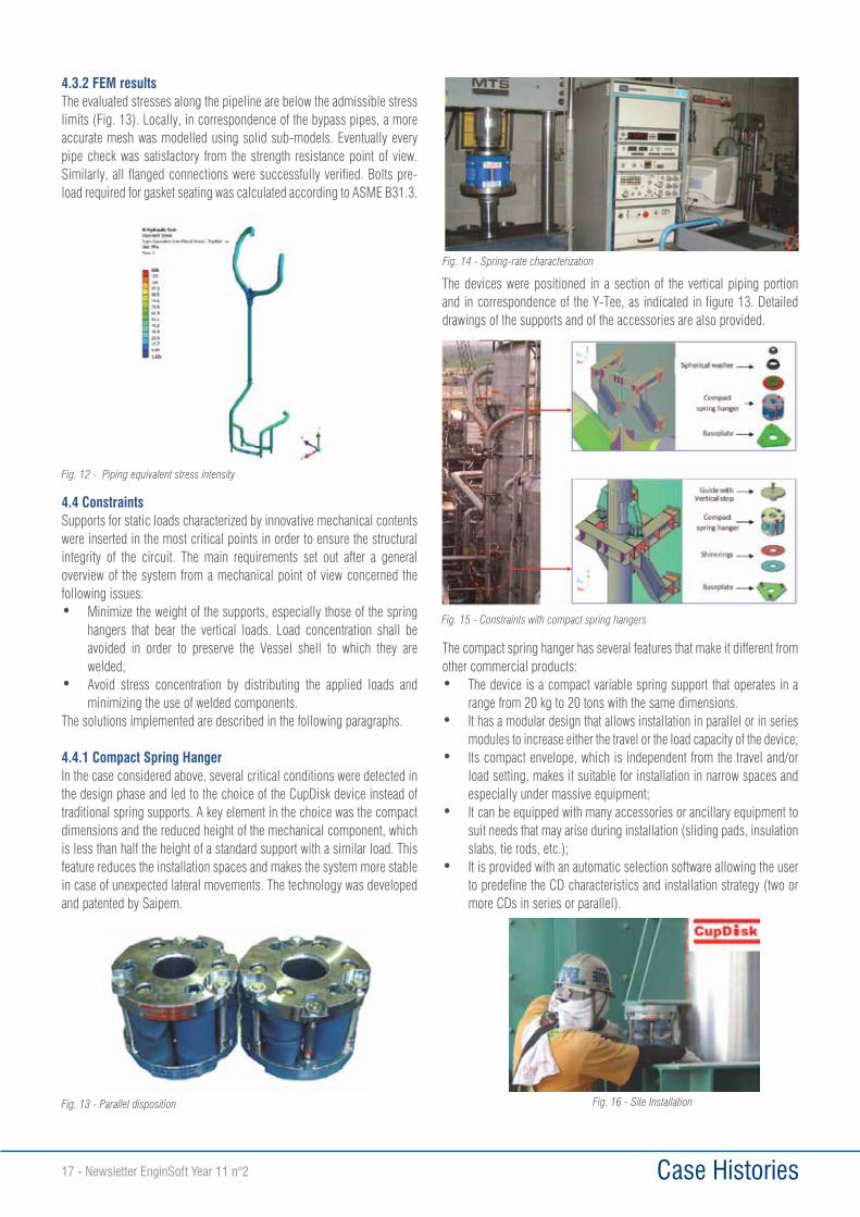
4.3.2 FEM resultsThe evaluated stresses along the pipeline are below the admissible stress limits (Fig. 13). Locally, in correspondence of the bypass pipes, a more accurate mesh was modelled using solid sub-models. Eventually every pipe check was satisfactory from the strength resistance point of view. Similarly, all flanged connections were successfully verified. Bolts pre-load required for gasket seating was calculated according to ASME B31.3.
4.4 ConstraintsSupports for static loads characterized by innovative mechanical contents were inserted in the most critical points in order to ensure the structural integrity of the circuit. The main requirements set out after a general overview of the system from a mechanical point of view concerned the following issues:• Minimize the weight of the supports, especially those of the spring
hangers that bear the vertical loads. Load concentration shall be avoided in order to preserve the Vessel shell to which they are welded;
• Avoid stress concentration by distributing the applied loads and minimizing the use of welded components.
The solutions implemented are described in the following paragraphs.
4.4.1 Compact Spring HangerIn the case considered above, several critical conditions were detected in the design phase and led to the choice of the CupDisk device instead of traditional spring supports. A key element in the choice was the compact dimensions and the reduced height of the mechanical component, which is less than half the height of a standard support with a similar load. This feature reduces the installation spaces and makes the system more stable in case of unexpected lateral movements. The technology was developed and patented by Saipem.
The devices were positioned in a section of the vertical piping portion and in correspondence of the Y-Tee, as indicated in figure 13. Detailed drawings of the supports and of the accessories are also provided.
The compact spring hanger has several features that make it different from other commercial products:• The device is a compact variable spring support that operates in a
range from 20 kg to 20 tons with the same dimensions.• It has a modular design that allows installation in parallel or in series
modules to increase either the travel or the load capacity of the device;• Its compact envelope, which is independent from the travel and/or
load setting, makes it suitable for installation in narrow spaces and especially under massive equipment;
• It can be equipped with many accessories or ancillary equipment to suit needs that may arise during installation (sliding pads, insulation slabs, tie rods, etc.);
• It is provided with an automatic selection software allowing the user to predefine the CD characteristics and installation strategy (two or more CDs in series or parallel).
Fig. 12 - Piping equivalent stress intensity
Fig. 13 - Parallel disposition
Fig. 14 - Spring-rate characterization
Fig. 15 - Constraints with compact spring hangers
Fig. 16 - Site Installation
Case Histories Newsletter EnginSoft Year 11 n°2 - 18
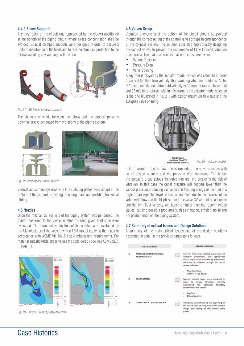
4.4.2 Elbow SupportsA critical point of the circuit was represented by the elbows positioned at the bottom of the piping circuit, where stress concentration shall be avoided. Special clamped supports were designed in order to ensure a uniform distribution of the loads and to provide structural protection to the elbows avoiding any welding on the elbow.
The absence of welds between the elbow and the support prevents potential cracks generated from vibrations of the piping system.
Vertical adjustment systems with PTFE sliding plates were added at the bottom of the support, providing a bearing plane and enabling horizontal sliding.
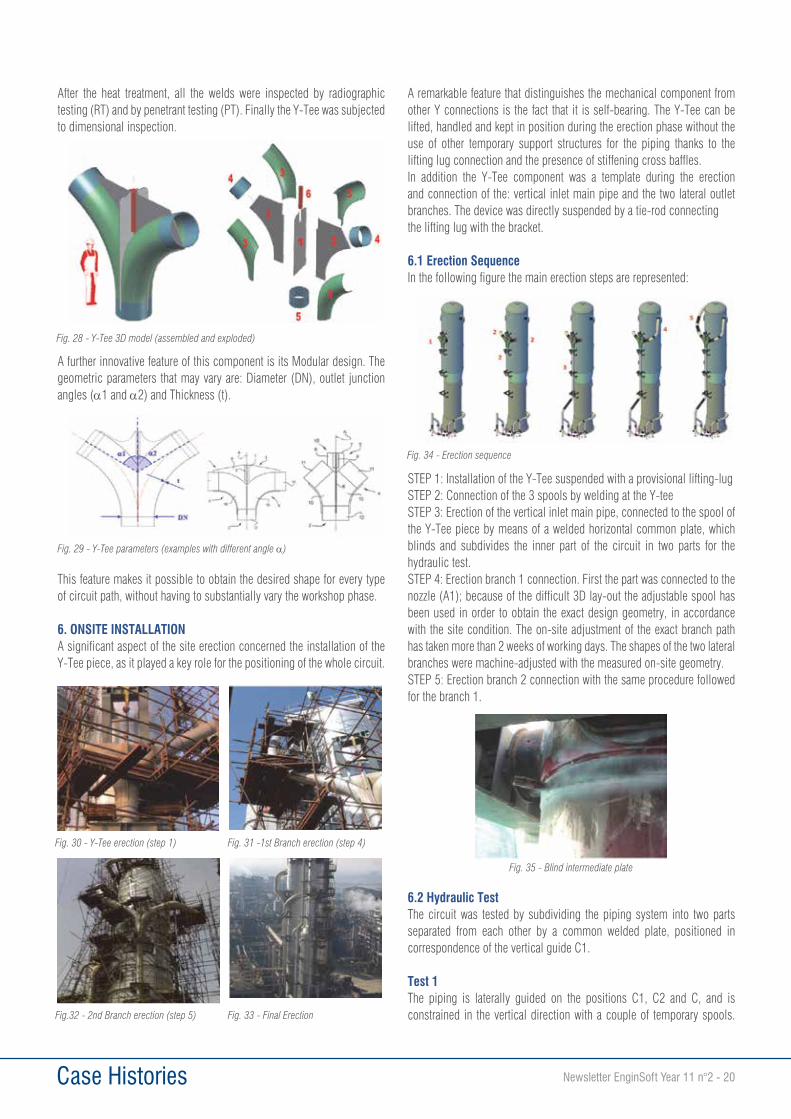
4.5 NozzlesOnce the mechanical analysis of the piping system was performed, the loads transferred to the vessel nozzles for each given load case were evaluated. The structural verification of the nozzles was developed by the Manufacturer of the vessel, with a FEM model applying the loads in accordance with ASME VIII Div.2 App.4 criteria and requirements. For material and allowable stress values the considered code was ASME SEC.II, PART D.
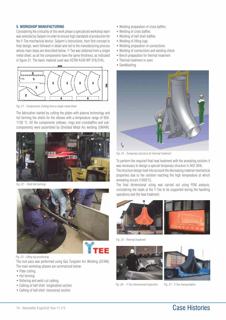
4.6 Valves GroupVibration phenomena at the bottom of the circuit should be avoided through the correct setting of the control valves groups in correspondence of the by-pass system. The solution consisted appropriately designing the control valves to prevent the occurrence of Flow Induced Vibration phenomena. The main parameters that were considered were:• Vapour Pressure• Pressure Drop• Valve OpeningA key role is played by the actuator model, which was selected in order to control the fluid trim velocity, thus avoiding vibration problems. As for ISA recommendations, trim fluid velocity is 30 m/s for mono-phase fluid and 23 m/s for bi-phase fluid. In this example the actuator model selected is the one illustrated in fig. 21, with design maximum flow rate and the assigned valve opening.
If the maximum design flow rate is exceeded, the valve operates with an off-design opening and the pressure drop increases. The higher the pressure drops across the valve trim are, the greater is the risk of vibration. In this case the outlet pressure will become lower than the vapour pressure producing cavitation and flashing energy of the fluid at a higher-than-expected level. In such a condition, due to the increase of the volumetric flow and the bi-phase fluid, the valve CV will not be adequate and the trim fluid velocity will become higher than the recommended values, causing possible problems such as vibration, erosion, noise and FIV phenomenon on the piping system.
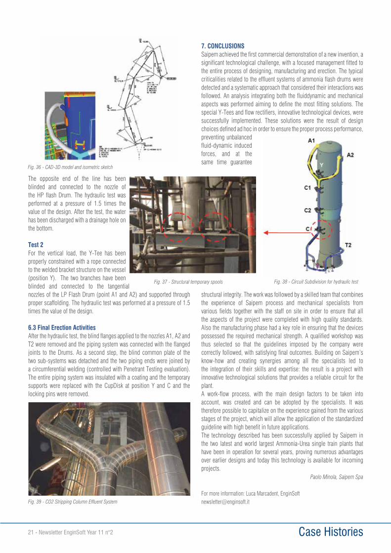
4.7 Summary of critical Issues and Design SolutionsA summary of the main critical issues and of the design solutions described in detail in the previous paragraphs follows.
Fig. 17 - 3D-Model of elbow supports
Fig. 18 - Vertical adjustment system
Fig. 19 - Nozzle stress (by Manufacturer)
Fig. 20 - Actuator model
Case Histories19 - Newsletter EnginSoft Year 11 n°2
5. WORKSHOP MANUFACTURINGConsidering the criticality of this work phase a specialized workshop team was selected by Saipem in order to ensure high standards of production for the Y-Tee mechanical device. Saipem’s instructions, from first concept to final design, were followed in detail and led to the manufacturing process whose main steps are described below. Y-Tee was obtained from a single metal sheet, as all the components have the same thickness, as indicated in figure 21. The basic material used was ASTM A430 WP 316/316L.
The fabrication started by cutting the plates with plasma technology and hot forming the shells for the elbows with a temperature range of 950-1150 °C. All the components (elbows, rings and crossbaffles and sub-components) were assembled by Shielded Metal Arc welding (SMAW).
The root pass was performed using Gas Tungsten Arc Welding (GTAW). The main workshop phases are summarized below:• Plate cutting• Hot forming• Rollering and weld-cut calking• Calking of half shell: longitudinal section• Calking of half shell: transversal section
• Welding preparation of cross baffles• Welding of cross baffles• Welding of half shell-baffles• Welding of lifting lugs• Welding preparation of connections• Welding of connections and welding check• Bench preparation for thermal treatment• Thermal treatment in oven• Sandblasting
To perform the required final heat treatment with the annealing solution it was necessary to design a special temporary structure in AISI 304L.The structure design took into account the decreasing material mechanical properties due to the solution reaching the high temperature at which annealing occurs (1050°C).The final dimensional sizing was carried out using FEM analysis, considering the loads of the Y-Tee to be supported during the handling operations and the heat treatment.
Fig. 21 - Components-Cutting from a single metal sheet
Fig. 22 - Shell Hot forming
Fig. 23 - Lifting lug positioning
Fig. 24 - Temporary structure for thermal treatment
Fig. 25 - Thermal treatment
Fig. 26 - Y-Tee dimensional inspection Fig. 27 - Y-Tee transportation
Case Histories Newsletter EnginSoft Year 11 n°2 - 20
After the heat treatment, all the welds were inspected by radiographic testing (RT) and by penetrant testing (PT). Finally the Y-Tee was subjected to dimensional inspection.
A further innovative feature of this component is its Modular design. The geometric parameters that may vary are: Diameter (DN), outlet junction angles (α1 and α2) and Thickness (t).
This feature makes it possible to obtain the desired shape for every type of circuit path, without having to substantially vary the workshop phase.
6. ONSITE INSTALLATIONA significant aspect of the site erection concerned the installation of the Y-Tee piece, as it played a key role for the positioning of the whole circuit.
A remarkable feature that distinguishes the mechanical component from other Y connections is the fact that it is self-bearing. The Y-Tee can be lifted, handled and kept in position during the erection phase without the use of other temporary support structures for the piping thanks to the lifting lug connection and the presence of stiffening cross baffles.In addition the Y-Tee component was a template during the erection and connection of the: vertical inlet main pipe and the two lateral outlet branches. The device was directly suspended by a tie-rod connectingthe lifting lug with the bracket.
6.1 Erection SequenceIn the following figure the main erection steps are represented:
STEP 1: Installation of the Y-Tee suspended with a provisional lifting-lugSTEP 2: Connection of the 3 spools by welding at the Y-teeSTEP 3: Erection of the vertical inlet main pipe, connected to the spool of the Y-Tee piece by means of a welded horizontal common plate, which blinds and subdivides the inner part of the circuit in two parts for the hydraulic test.STEP 4: Erection branch 1 connection. First the part was connected to the nozzle (A1); because of the difficult 3D lay-out the adjustable spool has been used in order to obtain the exact design geometry, in accordance with the site condition. The on-site adjustment of the exact branch path has taken more than 2 weeks of working days. The shapes of the two lateral branches were machine-adjusted with the measured on-site geometry.STEP 5: Erection branch 2 connection with the same procedure followed for the branch 1.
6.2 Hydraulic TestThe circuit was tested by subdividing the piping system into two parts separated from each other by a common welded plate, positioned in correspondence of the vertical guide C1.
Test 1The piping is laterally guided on the positions C1, C2 and C, and is constrained in the vertical direction with a couple of temporary spools.
Fig. 28 - Y-Tee 3D model (assembled and exploded)
Fig. 29 - Y-Tee parameters (examples with different angle α)
Fig.32 - 2nd Branch erection (step 5) Fig. 33 - Final Erection
Fig. 30 - Y-Tee erection (step 1) Fig. 31 -1st Branch erection (step 4)
Fig. 34 - Erection sequence
Fig. 35 - Blind intermediate plate
Case Histories21 - Newsletter EnginSoft Year 11 n°2
The opposite end of the line has been blinded and connected to the nozzle of the HP flash Drum. The hydraulic test was performed at a pressure of 1.5 times the value of the design. After the test, the water has been discharged with a drainage hole on the bottom.
Test 2For the vertical load, the Y-Tee has been properly constrained with a rope connected to the welded bracket structure on the vessel (position Y). The two branches have been blinded and connected to the tangential nozzles of the LP Flash Drum (point A1 and A2) and supported through proper scaffolding. The hydraulic test was performed at a pressure of 1.5 times the value of the design.
6.3 Final Erection ActivitiesAfter the hydraulic test, the blind flanges applied to the nozzles A1, A2 and T2 were removed and the piping system was connected with the flanged joints to the Drums. As a second step, the blind common plate of the two sub-systems was detached and the two piping ends were joined by a circumferential welding (controlled with Penetrant Testing evaluation). The entire piping system was insulated with a coating and the temporary supports were replaced with the CupDisk at position Y and C and the locking pins were removed.
7. CONCLUSIONSSaipem achieved the first commercial demonstration of a new invention, a significant technological challenge, with a focused management fitted to the entire process of designing, manufacturing and erection. The typical criticalities related to the effluent systems of ammonia flash drums were detected and a systematic approach that considered their interactions was followed. An analysis integrating both the fluiddynamic and mechanical aspects was performed aiming to define the most fitting solutions. The special Y-Tees and flow rectifiers, innovative technological devices, were successfully implemented. These solutions were the result of design choices defined ad hoc in order to ensure the proper process performance, preventing unbalanced fluid-dynamic induced forces, and at the same time guarantee
structural integrity. The work was followed by a skilled team that combines the experience of Saipem process and mechanical specialists from various fields together with the staff on site in order to ensure that all the aspects of the project were completed with high quality standards. Also the manufacturing phase had a key role in ensuring that the devices possessed the required mechanical strength. A qualified workshop was thus selected so that the guidelines imposed by the company were correctly followed, with satisfying final outcomes. Building on Saipem’s know-how and creating synergies among all the specialists led to the integration of their skills and expertise: the result is a project with innovative technological solutions that provides a reliable circuit for the plant.A work-flow process, with the main design factors to be taken into account, was created and can be adopted by the specialists. It was therefore possible to capitalize on the experience gained from the various stages of the project, which will allow the application of the standardized guideline with high benefit in future applications.The technology described has been successfully applied by Saipem in the two latest and world largest Ammonia-Urea single train plants that have been in operation for several years, proving numerous advantages over earlier designs and today this technology is available for incoming projects.
Paolo Minola, Saipem Spa
For more information: Luca Marcadent, EnginSoft [email protected]
Fig. 36 - CAD-3D model and isometric sketch
Fig. 38 - Circuit Subdivision for hydraulic test Fig. 37 - Structural temporary spools
Fig. 39 - CO2 Stripping Column Effluent System
Case Histories Newsletter EnginSoft Year 11 n°2 - 22
EnginSoft and Saipem partnershipSaipem first began operating in the 1950’s and since then it has grown to be a world leader in the oil & gas contracting services sector, both onshore and offshore. A truly international company, Saipem employs over 48,000 people from more than 127 nationalities with distinctive capabilities in the design and the execution of large-scale offshore and onshore projects and technological competencies such as gas monetization and heavy oil exploitation.EnginSoft are very proud of our long standing links with Saipem, both at multiple sites and across varied technical disciplines. We respect Saipem’s core values focused on quality, innovation, integrity and global teamwork and in this newsletter our Editor in Chief has introduced the concept where everything is bound fast to everything else in the universe by a thousand invisible cords that cannot be broken. We believe this is reflected in our relationship with Saipem as it has grown and matured through multi-disciplinary teams that have crossed boundaries and shared in joint successes. To mention only one, we previously collaborated to design and build a genuinely, innovative system to simplify the towing and laying down of marine pipelines in shallow water fields. EnginSoft’s input was to verify the conceptual validity of the proposed system and to identify control characteristics. And in this newsletter we are delighted to share our latest partnership with Saipem, the design of two effluent piping systems for use in CO2 stripper columns in Ammonia Plants. EnginSoft worked as part of a large and dedicated team providing integrated fluid dynamic and mechanical aspects to the design solutions. This is detailed in the following feature by Paolo Minola, Saipem S.p.A. So we take this opportunity to thank Saipem for considering us once more to become an integral part of their team, to congratulate them on their success and to reflect on the invisible cords that cannot be broken when organisations have the ability to build meaningful relationships.
EnginSoft inOil&Gas IndustryThe Oil and Gas sector is challenging, complex and extremely high risk. This makes it a perfect fit for EnginSoft and our ability to optimise processes and products. In an environment where companies strive to maximize efficiency to improve overall costs in the prospecting and extraction of hydrocarbons, innovation is not only the key to business success but often a matter of life and death. This explains the necessary consideration of safety regulations and environmental issues as well as other external variables, such as technical and logistical factors in all projects.The industry is split into upstream, midstream and downstream sectors ranging from exploration and extraction, transportation and then final refining and distribution. All areas benefit from virtual solutions and the engineering simulation of their processes. EnginSoft has a substantive track record in Oil and Gas. This was originally focused around the Mediterranean and Africa but is now strategically expanding through collaboration with key partnerships across the globe. In the Upstream and Midstream sectors primary activities include the drilling of exploratory wells, operating these wells to uncover and extract the discovered energy source and the subsequent transportation of raw products to refineries. Here EnginSoft specialists can offer support in complex simulations for; reservoir and geology simulation, production phase simulation, subsea systems design and analysis, and offshore structures design and analysis.Engineering Simulation for the Downstream sector involves dealing with extracted hydrocarbons in their liquid form (petroleum) or their gaseous form (natural gas) and here EnginSoft engineers have undertaken a varied raft of projects including; heat and mass transfer in distillation columns, bulk liquid storage structures, process furnaces, the understanding of risers, regenerators and cyclones, refinery process units, gasification plants and petrochemical facilities. As with this month’s Saipem case study, where we combined fluid dynamics and mechanical-structural activities, EnginSoft focuses on multi-disciplinary technologies where our engineers have a clear understanding of what impact their specific part has on the whole project. Leading-edge technologies and methods are applied to specific contexts to support shortened development cycles and improved resource utilization. This holistic approach to our clients’ engineering simulation needs explains why EnginSoft is a growing partner of choice to support companies in design process innovation. But while we are passionate about our expertise, our main focus will always remain our clients. We are dedicated to building long term relations with all of our associates, whether we are working as an outsourced engineering simulation team or integrated within an in-house engineering simulation team. And so here we offer our warmest congratulations to Saipem for achieving unprecedented results with their Y-Tee device.
Case Histories23 - Newsletter EnginSoft Year 11 n°2
Saipem is a world-leading turnkey contractor in the oil & gas industry, providing engineering, procurement and construction services in the design and execution of large-scale offshore and onshore projects, as well as technological competencies for gas monetization and heavy oil exploitation. One of the main fields of activity of the onshore business unit is the construction of integrated fertilizer complexes to produce ammonia and urea. Saipem has contracted or licensed with its proprietary Snamprogetti™ Urea Technology more than 130 plants for a total urea production exceeding 222,000 metric tons per day all over the world. The recent Engro (Pakistan) and QAFCO V & VI (Qatar) projects hold the record of the world largest single-line urea units (3850 MTPD), thus overtaking the previous record of the Profertil (Argentina) plant (3250 MTPD).
UREA TECHNOLOGY & INNOVATION OVERVIEWUrea is nowadays the most widely used fertilizer thanks to its 46% wt nitrogen content which is higher than all other solid nitrogenous fertilizers on the market. Its use as a fertilizer covers more than 90% of its worldwide production. Moreover urea is used also in power plants and diesel engine exhaust systems to reduce emission of NOx gases by selective catalytic and non-catalytic reduction. In the chemical industry it is used instead as a raw material for the production of urea-formaldehyde and melamine-urea-formaldehide resins.
Urea is produced by synthesis from liquid ammonia and gaseous carbon dioxide. In the synthesis reactor (T = 180 - 190 °C, P = 15 - 16 MPaG), the ammonia and carbon dioxide react to form ammonium carbamate (NH2COONH4), a portion of which dehydrates to urea (NH2CONH2) and water according to the following reactions:
2 NH3 + CO2 1 NH2COONH4
NH2COONH4 1 NH2CONH2 + H2O
The fraction of ammonium carbamate that dehydrates is determined by the ratios of the various reagents, the operating temperature and pressure and the residence time in the reactor.Urea reactors are Plug-flow reactors (“PFR”) type equipped with dedicated distributors for the reagents and a number of sieve type trays (“Standard Design”) which consist of perforated plates that prevent back-flow of the heavier solution from the upper part downwards and favour the gas absorption in the liquid phase.The fluid dynamics of a Urea Reactor can be significantly improved by the introduction of the latest generation of high efficiency trays recently invented and patented by Saipem. The support of a systematic plan of fluid-dynamic simulations gave a significant contribution to the development of the innovative design.The proprietary SnamprogettiTM SuperCups (“New Design”) greatly increases the mixing of the liquid and gaseous phases, respectively ammonia and carbamate, and carbon dioxide, thus optimizing the product conversion rate in the reactor. The immediate benefit is the lower specific steam consumption requirement to decompose carbamate to CO2 and NH3 in downstream sections.This represents a further step ahead to get closest to the theoretical equilibrium conversion in the reactor. In fact, the increase in the reaction conversion is strictly dependent on the mixing conditions of ammonia, carbamate and carbon dioxide through the reactor so that the main purpose of these innovative trays is to further improve the contacting
The SuperCups Trays – Saipem’s further innovation in Urea Technology
Case Histories Newsletter EnginSoft Year 11 n°2 - 24
conditions among the reagents. Taking into consideration the necessity to minimize the pressure drop across the reactor, the improved mixing is obtained without any increase of compression energy for carbon dioxide.The innovative concept of the SnamprogettiTM SuperCups lies in the realization of a confined reaction space within the reactor tray geometry, the cups. They perform as a number of mixing units where ammonia is contacted with the gaseous CO2 in small bubbles. Once the reactants have swirled inside the cups, the mixed solution of product and non-reacted components is uniformly distributed on the upper part of the tray by means of the upper cup distributor. The outlet flow pattern ensures a further mixing of the solution coming from all the cups.
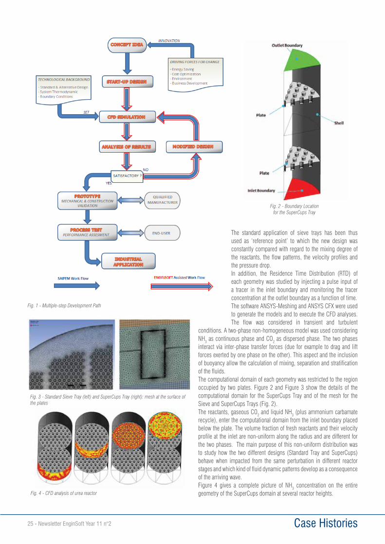
THE INNOVATION DEVELOPMENT PATHThe development of this innovative solution has been carried out with the support of a comprehensive CFD study. This has been a key tool in the design process from the initial concept idea to the final engineered solution.Figure 1 shows the multi-step development path followed in the creation of the new design. The blue arrows indicate the work flow directly followed by Saipem while the red-lined arrows refer to the steps where EnginSoft was involved for the CFD simulations. The driving force for innovation has come from the trend towards increasing plant efficiency with the aim to optimize the capital investment of the equipment, decrease the energy consumption of the high pressure section and therefore reduce the environmental impact of plant operation. It can be seen that the CFD study has been a core activity of the work flow, playing the most important role in the definition of the final design ready for industrial application.The CFD study first compared the performance of the new tray design with respect to the traditional plates in terms of fluid dynamic behaviour. Subsequently the CFD analysis was used to perform the fine-tuning of the tray design parameters. An iterative approach was applied so that the initial design coming out from the original concept idea (start-up design) was progressively improved until the design parameters provided a satisfactory output. The iterative “Simulate-Analyse-Redesign” approach delivered a reliable and detailed design which enabled a direct jump to an industrial scale prototype, thus skipping any intermediate phase.As a consequence, the theoretical design resulting from the simulation study was assessed in the industrial prototype step in terms of mechanical validation, manufacturing activities and maintenance constraints. All the technical problems were solved in order to ensure a feasible and economically convenient construction and to allow an easy installation and maintenance.In the later step of process test, the developed prototype was then installed in the industrial reactor of a urea producer with the aim to make the performance assessment of the new design.
THE CFD STUDY Two different geometries were investigated at each step of the iterative CFD study:• Standard Design: traditional perforated plate (Sieve Trays)• New Design: innovative plate with perforated cups
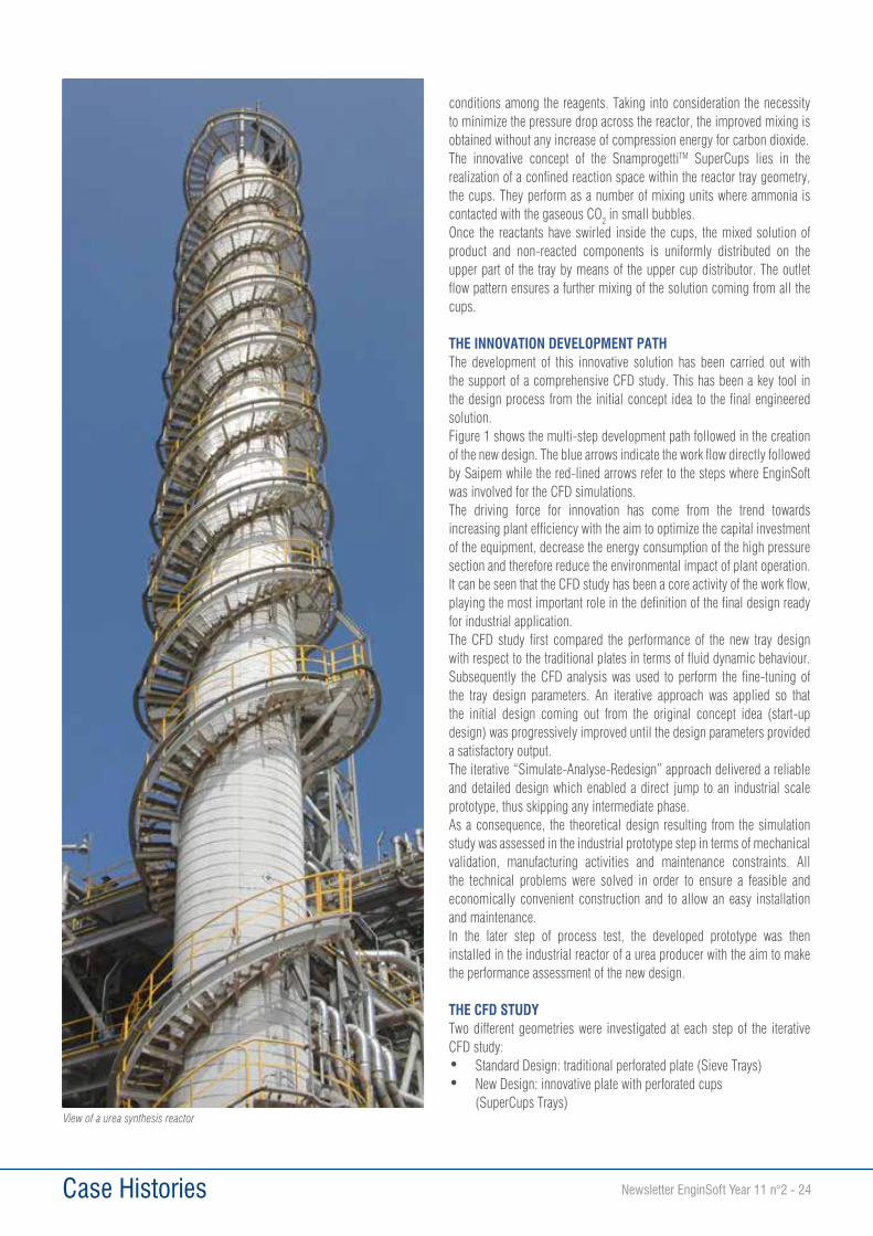
(SuperCups Trays)View of a urea synthesis reactor
Case Histories25 - Newsletter EnginSoft Year 11 n°2
The standard application of sieve trays has been thus used as ‘reference point’ to which the new design was constantly compared with regard to the mixing degree of the reactants, the flow patterns, the velocity profiles and the pressure drop.In addition, the Residence Time Distribution (RTD) of each geometry was studied by injecting a pulse input of a tracer in the inlet boundary and monitoring the tracer concentration at the outlet boundary as a function of time.The software ANSYS-Meshing and ANSYS CFX were used to generate the models and to execute the CFD analyses. The flow was considered in transient and turbulent
conditions. A two-phase non-homogeneous model was used considering NH3 as continuous phase and CO2 as dispersed phase. The two phases interact via inter-phase transfer forces (due for example to drag and lift forces exerted by one phase on the other). This aspect and the inclusion of buoyancy allow the calculation of mixing, separation and stratification of the fluids.The computational domain of each geometry was restricted to the region occupied by two plates. Figure 2 and Figure 3 show the details of the computational domain for the SuperCups Tray and of the mesh for the Sieve and SuperCups Trays (Fig. 2).The reactants, gaseous CO2 and liquid NH3 (plus ammonium carbamate recycle), enter the computational domain from the inlet boundary placed below the plate. The volume fraction of fresh reactants and their velocity profile at the inlet are non-uniform along the radius and are different for the two phases. The main purpose of this non-uniform distribution was to study how the two different designs (Standard Tray and SuperCups) behave when impacted from the same perturbation in different reactor stages and which kind of fluid dynamic patterns develop as a consequence of the arriving wave.Figure 4 gives a complete picture of NH3 concentration on the entire geometry of the SuperCups domain at several reactor heights.
Fig. 1 - Multiple-step Development Path
Fig. 2 - Boundary Location for the SuperCups Tray
Fig. 3 - Standard Sieve Tray (left) and SuperCups Tray (right): mesh at the surface of the plates
Fig. 4 - CFD analysis of urea reactor
Case Histories Newsletter EnginSoft Year 11 n°2 - 26
RESULTSThe peculiar behaviour of the SuperCups is characterized by a triple fluid-dynamic effect – Gas Equalizer, Mixer Reactor and Gas Distributor – which are described below.
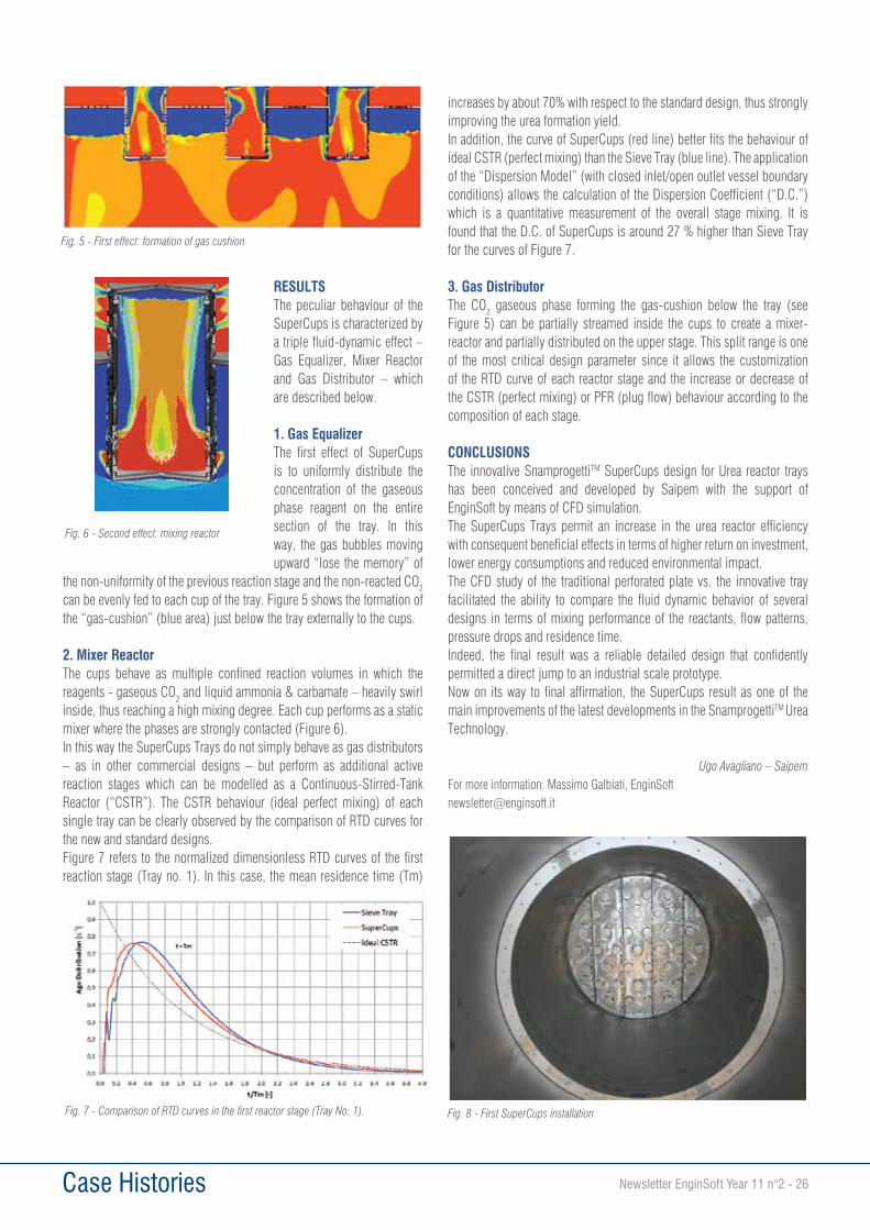
1. Gas EqualizerThe first effect of SuperCups is to uniformly distribute the concentration of the gaseous phase reagent on the entire section of the tray. In this way, the gas bubbles moving upward “lose the memory” of
the non-uniformity of the previous reaction stage and the non-reacted CO2 can be evenly fed to each cup of the tray. Figure 5 shows the formation of the “gas-cushion” (blue area) just below the tray externally to the cups.
2. Mixer ReactorThe cups behave as multiple confined reaction volumes in which the reagents - gaseous CO2 and liquid ammonia & carbamate – heavily swirl inside, thus reaching a high mixing degree. Each cup performs as a static mixer where the phases are strongly contacted (Figure 6).In this way the SuperCups Trays do not simply behave as gas distributors – as in other commercial designs – but perform as additional active reaction stages which can be modelled as a Continuous-Stirred-Tank Reactor (“CSTR”). The CSTR behaviour (ideal perfect mixing) of each single tray can be clearly observed by the comparison of RTD curves for the new and standard designs. Figure 7 refers to the normalized dimensionless RTD curves of the first reaction stage (Tray no. 1). In this case, the mean residence time (Tm)
increases by about 70% with respect to the standard design, thus strongly improving the urea formation yield.In addition, the curve of SuperCups (red line) better fits the behaviour of ideal CSTR (perfect mixing) than the Sieve Tray (blue line). The application of the “Dispersion Model” (with closed inlet/open outlet vessel boundary conditions) allows the calculation of the Dispersion Coefficient (“D.C.”) which is a quantitative measurement of the overall stage mixing. It is found that the D.C. of SuperCups is around 27 % higher than Sieve Tray for the curves of Figure 7.
3. Gas DistributorThe CO2 gaseous phase forming the gas-cushion below the tray (see Figure 5) can be partially streamed inside the cups to create a mixer-reactor and partially distributed on the upper stage. This split range is one of the most critical design parameter since it allows the customization of the RTD curve of each reactor stage and the increase or decrease of the CSTR (perfect mixing) or PFR (plug flow) behaviour according to the composition of each stage.
CONCLUSIONSThe innovative SnamprogettiTM SuperCups design for Urea reactor trays has been conceived and developed by Saipem with the support of EnginSoft by means of CFD simulation.The SuperCups Trays permit an increase in the urea reactor efficiency with consequent beneficial effects in terms of higher return on investment, lower energy consumptions and reduced environmental impact.The CFD study of the traditional perforated plate vs. the innovative tray facilitated the ability to compare the fluid dynamic behavior of several designs in terms of mixing performance of the reactants, flow patterns, pressure drops and residence time.Indeed, the final result was a reliable detailed design that confidently permitted a direct jump to an industrial scale prototype.Now on its way to final affirmation, the SuperCups result as one of the main improvements of the latest developments in the SnamprogettiTM Urea Technology.
Ugo Avagliano – SaipemFor more information: Massimo Galbiati, [email protected]
Fig. 5 - First effect: formation of gas cushion
Fig. 6 - Second effect: mixing reactor
Fig. 7 - Comparison of RTD curves in the first reactor stage (Tray No. 1). Fig. 8 - First SuperCups installation
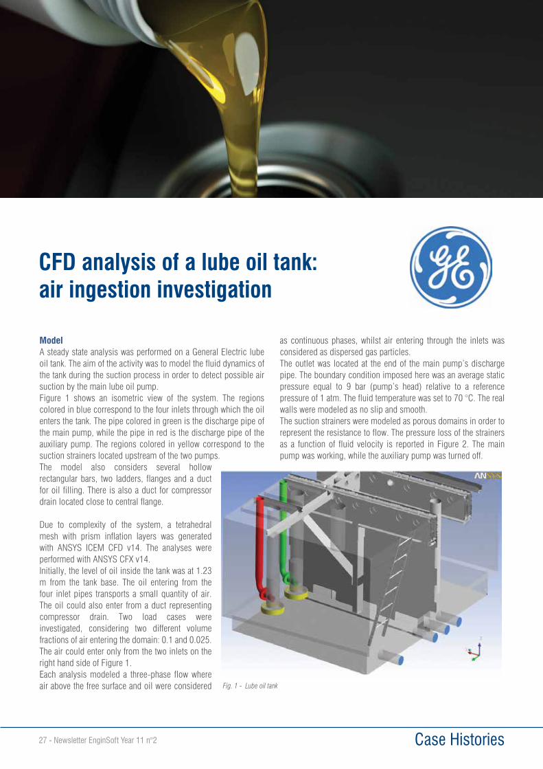
Case Histories27 - Newsletter EnginSoft Year 11 n°2
ModelA steady state analysis was performed on a General Electric lube oil tank. The aim of the activity was to model the fluid dynamics of the tank during the suction process in order to detect possible air suction by the main lube oil pump.Figure 1 shows an isometric view of the system. The regions colored in blue correspond to the four inlets through which the oil enters the tank. The pipe colored in green is the discharge pipe of the main pump, while the pipe in red is the discharge pipe of the auxiliary pump. The regions colored in yellow correspond to the suction strainers located upstream of the two pumps.The model also considers several hollow rectangular bars, two ladders, flanges and a duct for oil filling. There is also a duct for compressor drain located close to central flange.
Due to complexity of the system, a tetrahedral mesh with prism inflation layers was generated with ANSYS ICEM CFD v14. The analyses were performed with ANSYS CFX v14.Initially, the level of oil inside the tank was at 1.23 m from the tank base. The oil entering from the four inlet pipes transports a small quantity of air. The oil could also enter from a duct representing compressor drain. Two load cases were investigated, considering two different volume fractions of air entering the domain: 0.1 and 0.025. The air could enter only from the two inlets on the right hand side of Figure 1.Each analysis modeled a three-phase flow where air above the free surface and oil were considered
as continuous phases, whilst air entering through the inlets was considered as dispersed gas particles.The outlet was located at the end of the main pump’s discharge pipe. The boundary condition imposed here was an average static pressure equal to 9 bar (pump’s head) relative to a reference pressure of 1 atm. The fluid temperature was set to 70 °C. The real walls were modeled as no slip and smooth.The suction strainers were modeled as porous domains in order to represent the resistance to flow. The pressure loss of the strainers as a function of fluid velocity is reported in Figure 2. The main pump was working, while the auxiliary pump was turned off.
CFD analysis of a lube oil tank: air ingestion investigation
Fig. 1 - Lube oil tank
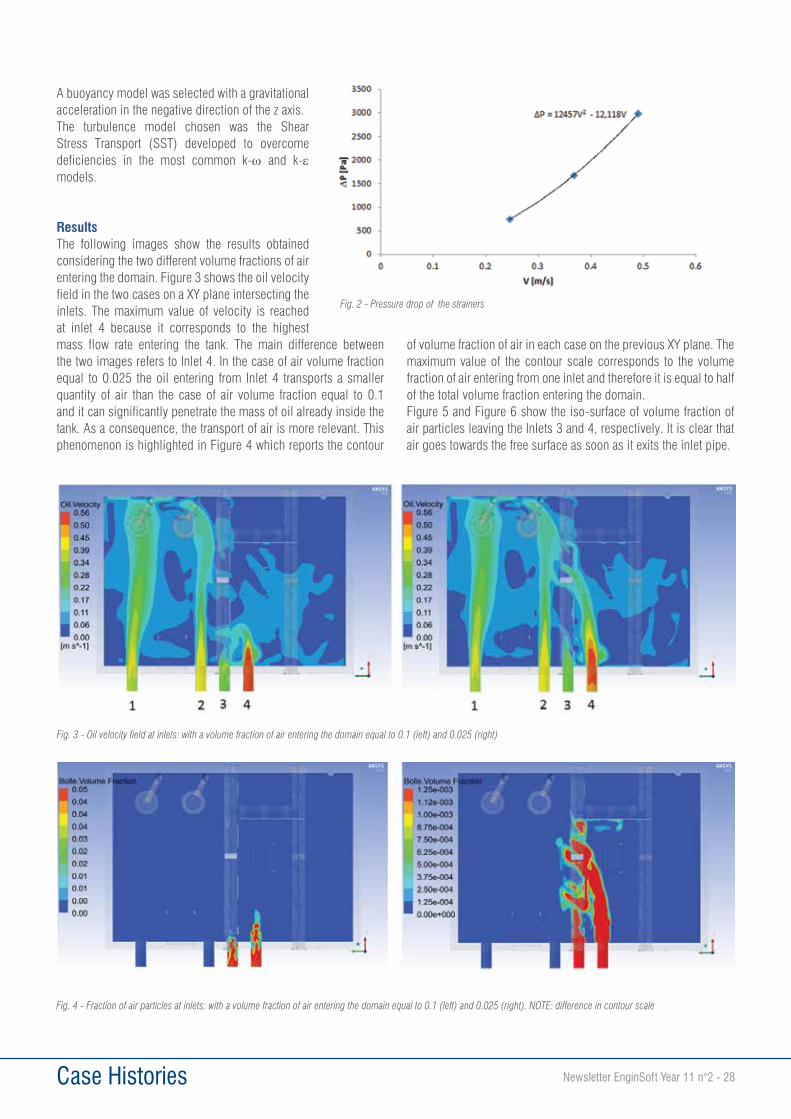
Case Histories Newsletter EnginSoft Year 11 n°2 - 28
A buoyancy model was selected with a gravitational acceleration in the negative direction of the z axis.The turbulence model chosen was the Shear Stress Transport (SST) developed to overcome deficiencies in the most common k-ω and k-ε models.
ResultsThe following images show the results obtained considering the two different volume fractions of air entering the domain. Figure 3 shows the oil velocity field in the two cases on a XY plane intersecting the inlets. The maximum value of velocity is reached at inlet 4 because it corresponds to the highest mass flow rate entering the tank. The main difference between the two images refers to Inlet 4. In the case of air volume fraction equal to 0.025 the oil entering from Inlet 4 transports a smaller quantity of air than the case of air volume fraction equal to 0.1 and it can significantly penetrate the mass of oil already inside the tank. As a consequence, the transport of air is more relevant. This phenomenon is highlighted in Figure 4 which reports the contour
of volume fraction of air in each case on the previous XY plane. The maximum value of the contour scale corresponds to the volume fraction of air entering from one inlet and therefore it is equal to half of the total volume fraction entering the domain.Figure 5 and Figure 6 show the iso-surface of volume fraction of air particles leaving the Inlets 3 and 4, respectively. It is clear that air goes towards the free surface as soon as it exits the inlet pipe.
Fig. 4 - Fraction of air particles at inlets: with a volume fraction of air entering the domain equal to 0.1 (left) and 0.025 (right). NOTE: difference in contour scale
Fig. 3 - Oil velocity field at inlets: with a volume fraction of air entering the domain equal to 0.1 (left) and 0.025 (right)
Fig. 2 - Pressure drop of the strainers
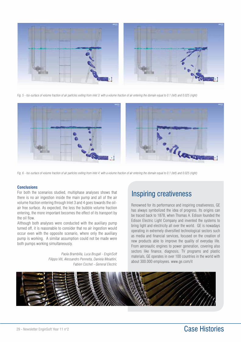
Case Histories29 - Newsletter EnginSoft Year 11 n°2
ConclusionsFor both the scenarios studied, multiphase analyses shows that there is no air ingestion inside the main pump and all of the air volume fraction entering through Inlet 3 and 4 goes towards the oil-air free surface. As expected, the less the bubble volume fraction entering, the more important becomes the effect of its transport by the oil flow.Although both analyses were conducted with the auxiliary pump turned off, it is reasonable to consider that no air ingestion would occur even with the opposite scenario, where only the auxiliary pump is working. A similar assumption could not be made were both pumps working simultaneously.
Paola Brambilla, Luca Brugali - EnginSoftFilippo Viti, Alessandro Pennetta, Daniela Meiattini,
Fabien Cochet - General Electric
Fig. 6 - Iso-surface of volume fraction of air particles exiting from inlet 4: with a volume fraction of air entering the domain equal to 0.1 (left) and 0.025 (right)
Fig. 5 - Iso-surface of volume fraction of air particles exiting from inlet 3: with a volume fraction of air entering the domain equal to 0.1 (left) and 0.025 (right)
Inspiring creativenessRenowned for its performance and inspiring creativeness, GE has always symbolized the idea of progress. Its origins can be traced back to 1878, when Thomas A. Edison founded the Edison Electric Light Company and invented the systems to bring light and electricity all over the world. GE is nowadays operating in extremely diversified technological sectors such as media and financial services, focused on the creation of new products able to improve the quality of everyday life. From aeronautic engines to power generation, covering also sectors like finance, diagnosis, TV programs and plastic materials, GE operates in over 100 countries in the world with about 300.000 employees. www.ge.com/it
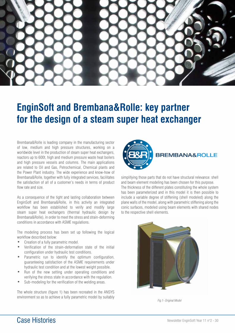
Case Histories Newsletter EnginSoft Year 11 n°2 - 30
Brembana&Rolle is leading company in the manufacturing sector of low, medium and high pressure structures, working on a worldwide level in the production of steam super heat exchangers, reactors up to 600t, high and medium pressure waste heat boilers and high pressure vessels and columns. The main applications are related to Oil and Gas, Petrochemical, Chemical plants and the Power Plant industry. The wide experience and know-how of Brembana&Rolle, together with fully integrated services, facilitates the satisfaction of all of a customer’s needs in terms of product flow rate and size.
As a consequence of the tight and lasting collaboration between EnginSoft and Brembana&Rolle, in this activity an integrated workflow has been established to verify and modify large steam super heat exchangers (thermal hydraulic design by Brembana&Rolle), in order to meet the stress and strain-deforming conditions in accordance with ASME regulations.
The modeling process has been set up following the logical workflow described below:• Creation of a fully parametric model.• Verification of the strain-deformation state of the initial
configuration under hydraulic test conditions.• Parametric run to identify the optimum configuration,
guaranteeing satisfaction of the ASME requirements under hydraulic test condition and at the lowest weight possible.
• Run of the new setting under operating conditions and verifying the stress state in accordance with the regulation.
• Sub-modeling for the verification of the welding areas.
The whole structure (figure 1) has been recreated in the ANSYS environment so as to achieve a fully parametric model by suitably
simplifying those parts that do not have structural relevance: shell and beam element modeling has been chosen for this purpose. The thickness of the different plates constituting the whole system has been parameterized and in this model it is then possible to include a variable degree of stiffening (shell modeled) along the plane walls of the model, along with parametric stiffening along the conic surfaces, modeled using beam elements with shared nodes to the respective shell elements.
EnginSoft and Brembana&Rolle: key partner for the design of a steam super heat exchanger
Fig.1- Original Model
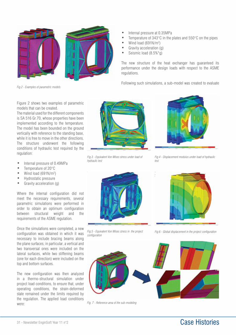
Case Histories31 - Newsletter EnginSoft Year 11 n°2
Figure 2 shows two examples of parametric models that can be created.The material used for the different components is SA 516 Gr.70, whose properties have been implemented according to the temperature. The model has been bounded on the ground vertically with reference to the standing base, while it is free to move in the other directions. The structure underwent the following conditions of hydraulic test required by the regulation:
• Internal pressure of 0.49MPa• Temperature of 20°C• Wind load (691N/m2)• Hydrostatic pressure • Gravity acceleration (g)
Where the internal configuration did not meet the necessary requirements, several parametric simulations were performed in order to obtain an optimum configuration between structural weight and the requirements of the ASME regulation.
Once the simulations were completed, a new configuration was obtained in which it was necessary to include bracing beams along the plane surfaces; in particular, a vertical and two transversal ones were included on the lateral surfaces, while two stiffening beams (one for each direction) were included on the top and bottom surfaces.
The new configuration was then analyzed in a thermo-structural simulation under project load conditions, to ensure that, under operating conditions, the strain-deformed state remained under the limits required by the regulation. The applied load conditions were:
• Internal pressure at 0.35MPa• Temperature of 343°C in the plates and 550°C on the pipes • Wind load (691N/m2)• Gravity acceleration (g)• Seismic load (8.5%*g)
The new structure of the heat exchanger has guaranteed its performance under the design loads with respect to the ASME regulations.
Following such simulations, a sub-model was created to evaluate Fig.2 - Examples of parametric models
Fig.3 - Equivalent Von Mises stress under load of hydraulic test
Fig.4 - Displacement modulus under load of hydraulic test
Fig.5 - Equivalent Von Mises stress in the project configuration
Fig.6 - Global displacement in the project configuration
Fig. 7 - Reference area of the sub-modeling
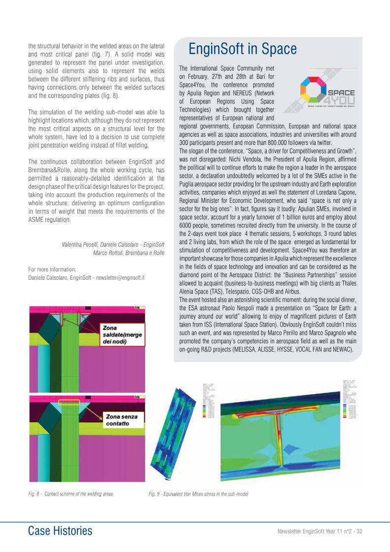
Case Histories Newsletter EnginSoft Year 11 n°2 - 32
EnginSoft in SpaceThe International Space Community met on February, 27th and 28th at Bari for Space4You, the conference promoted by Apulia Region and NEREUS (Network of European Regions Using Space Technologies) which brought together representatives of European national and regional governments, European Commission, European and national space agencies as well as space associations, industries and universities with around 300 participants present and more than 800.000 followers via twitter.The slogan of the conference, “Space, a driver for Competitiveness and Growth”, was not disregarded: Nichi Vendola, the President of Apulia Region, affirmed the political will to continue efforts to make the region a leader in the aerospace sector, a declaration undoubtedly welcomed by a lot of the SMEs active in the Puglia aerospace sector providing for the upstream industry and Earth exploration activities, companies which enjoyed as well the statement of Loredana Capone, Regional Minister for Economic Development, who said “space is not only a sector for the big ones”. In fact, figures say it loudly: Apulian SMEs, involved in space sector, account for a yearly turnover of 1 billion euros and employ about 6000 people, sometimes recruited directly from the university. In the course of the 2-days event took place 4 thematic sessions, 5 workshops, 3 round tables and 2 living labs, from which the role of the space emerged as fundamental for stimulation of competitiveness and development. Space4You was therefore an important showcase for those companies in Apulia which represent the excellence in the fields of space technology and innovation and can be considered as the diamond point of the Aerospace District: the “Business Partnerships” session allowed to acquaint (business-to-business meetings) with big clients as Thales Alenia Space (TAS), Telespazio, CGS-OHB and Airbus.The event hosted also an astonishing scientific moment: during the social dinner, the ESA astronaut Paolo Nespoli made a presentation on “Space for Earth: a journey around our world” allowing to enjoy of magnificent pictures of Earth taken from ISS (International Space Station). Obviously EnginSoft couldn’t miss such an event, and was represented by Marco Perillo and Marco Spagnolo who promoted the company’s competencies in aerospace field as well as the main on-going R&D projects (MELISSA, ALISSE, HYSSE, VOCAL FAN and NEWAC).
the structural behavior in the welded areas on the lateral and most critical panel (fig. 7). A solid model was generated to represent the panel under investigation, using solid elements also to represent the welds between the different stiffening ribs and surfaces, thus having connections only between the welded surfaces and the corresponding plates (fig. 8).
The simulation of the welding sub-model was able to highlight locations which, although they do not represent the most critical aspects on a structural level for the whole system, have led to a decision to use complete joint penetration welding instead of fillet welding.
The continuous collaboration between EnginSoft and Brembana&Rolle, along the whole working cycle, has permitted a reasonably-detailed identification at the design phase of the critical design features for the project, taking into account the production requirements of the whole structure; delivering an optimum configuration in terms of weight that meets the requirements of the ASME regulation.
Valentina Peselli, Daniele Calsolaro - EnginSoftMarco Rottoli, Brembana e Rolle
For more information:Daniele Calsolaro, EnginSoft - [email protected]
Fig. 8 - Contact scheme of the welding areas Fig. 9 - Equivalent Von Mises stress in the sub-model
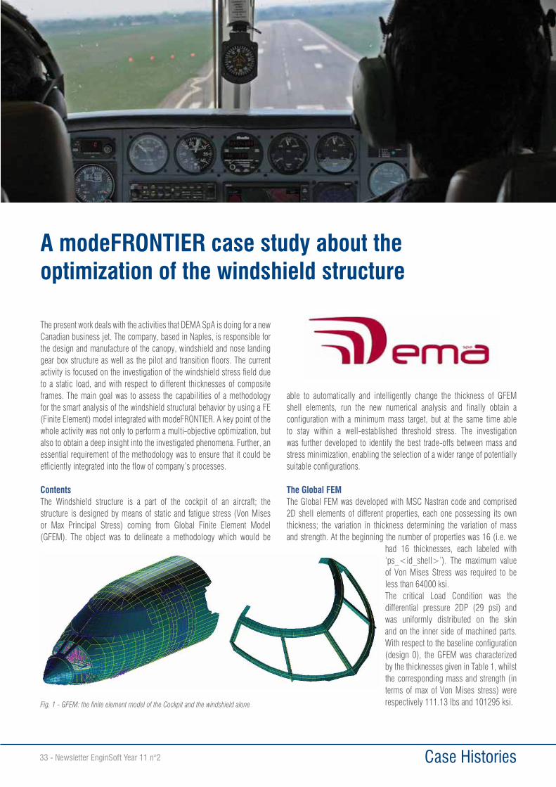
Case Histories33 - Newsletter EnginSoft Year 11 n°2
A modeFRONTIER case study about the optimization of the windshield structure
The present work deals with the activities that DEMA SpA is doing for a new Canadian business jet. The company, based in Naples, is responsible for the design and manufacture of the canopy, windshield and nose landing gear box structure as well as the pilot and transition floors. The current activity is focused on the investigation of the windshield stress field due to a static load, and with respect to different thicknesses of composite frames. The main goal was to assess the capabilities of a methodology for the smart analysis of the windshield structural behavior by using a FE (Finite Element) model integrated with modeFRONTIER. A key point of the whole activity was not only to perform a multi-objective optimization, but also to obtain a deep insight into the investigated phenomena. Further, an essential requirement of the methodology was to ensure that it could be efficiently integrated into the flow of company’s processes.
ContentsThe Windshield structure is a part of the cockpit of an aircraft; the structure is designed by means of static and fatigue stress (Von Mises or Max Principal Stress) coming from Global Finite Element Model (GFEM). The object was to delineate a methodology which would be
able to automatically and intelligently change the thickness of GFEM shell elements, run the new numerical analysis and finally obtain a configuration with a minimum mass target, but at the same time able to stay within a well-established threshold stress. The investigation was further developed to identify the best trade-offs between mass and stress minimization, enabling the selection of a wider range of potentially suitable configurations.
The Global FEMThe Global FEM was developed with MSC Nastran code and comprised 2D shell elements of different properties, each one possessing its own thickness; the variation in thickness determining the variation of mass and strength. At the beginning the number of properties was 16 (i.e. we
had 16 thicknesses, each labeled with ‘ps_<id_shell>’). The maximum value of Von Mises Stress was required to be less than 64000 ksi. The critical Load Condition was the differential pressure 2DP (29 psi) and was uniformly distributed on the skin and on the inner side of machined parts. With respect to the baseline configuration (design 0), the GFEM was characterized by the thicknesses given in Table 1, whilst the corresponding mass and strength (in terms of max of Von Mises stress) were respectively 111.13 lbs and 101295 ksi. Fig. 1 - GFEM: the finite element model of the Cockpit and the windshield alone
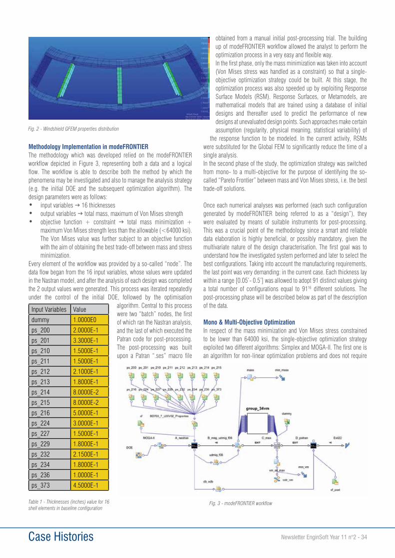
Case Histories Newsletter EnginSoft Year 11 n°2 - 34
Methodology Implementation in modeFRONTIERThe methodology which was developed relied on the modeFRONTIER workflow depicted in Figure 3, representing both a data and a logical flow. The workflow is able to describe both the method by which the phenomena may be investigated and also to manage the analysis strategy (e.g. the initial DOE and the subsequent optimization algorithm). The design parameters were as follows: • input variables g 16 thicknesses• output variables g total mass, maximum of Von Mises strength• objective function + constraint g total mass minimization +
maximum Von Mises strength less than the allowable (<64000 ksi). The Von Mises value was further subject to an objective function with the aim of obtaining the best trade-off between mass and stress minimization.
Every element of the workflow was provided by a so-called “node”. The data flow began from the 16 input variables, whose values were updated in the Nastran model, and after the analysis of each design was completed the 2 output values were generated. This process was iterated repeatedly under the control of the initial DOE, followed by the optimisation
algorithm. Central to this process were two “batch” nodes, the first of which ran the Nastran analysis, and the last of which executed the Patran code for post-processing. The post-processing was built upon a Patran “.ses” macro file
obtained from a manual initial post-processing trial. The building up of modeFRONTIER workflow allowed the analyst to perform the optimization process in a very easy and flexible way.In the first phase, only the mass minimization was taken into account (Von Mises stress was handled as a constraint) so that a single-objective optimization strategy could be built. At this stage, the optimization process was also speeded up by exploiting Response Surface Models (RSM). Response Surfaces, or Metamodels, are mathematical models that are trained using a database of initial designs and thereafter used to predict the performance of new designs at unevaluated design points. Such approaches make certain assumption (regularity, physical meaning, statistical variability) of
the response function to be modeled. In the current activity, RSMs were substituted for the Global FEM to significantly reduce the time of a single analysis.In the second phase of the study, the optimization strategy was switched from mono- to a multi-objective for the purpose of identifying the so-called “Pareto Frontier” between mass and Von Mises stress, i.e. the best trade-off solutions.
Once each numerical analyses was performed (each such configuration generated by modeFRONTIER being referred to as a “design”), they were evaluated by means of suitable instruments for post-processing. This was a crucial point of the methodology since a smart and reliable data elaboration is highly beneficial, or possibly mandatory, given the multivariate nature of the design characterisation. The first goal was to understand how the investigated system performed and later to select the best configurations. Taking into account the manufacturing requirements, the last point was very demanding: in the current case. Each thickness lay within a range [0.05’- 0.5’] was allowed to adopt 91 distinct values giving a total number of configurations equal to 9116 different solutions. The post-processing phase will be described below as part of the description of the data.
Mono & Multi-Objective OptimizationIn respect of the mass minimization and Von Mises stress constrained to be lower than 64000 ksi, the single-objective optimization strategy exploited two different algorithms: Simplex and MOGA-II. The first one is an algorithm for non-linear optimization problems and does not require
Fig. 2 - Windshield GFEM properties distribution
Table 1 - Thicknesses (inches) value for 16 shell elements in baseline configuration
Fig. 3 - modeFRONTIER workflow
Input Variables Value
dummy 1.0000E0
ps_200 2.0000E-1
ps_201 3.3000E-1
ps_210 1.5000E-1
ps_211 1.5000E-1
ps_212 2.1000E-1
ps_213 1.8000E-1
ps_214 8.0000E-2
ps_215 8.0000E-2
ps_216 5.0000E-1
ps_224 3.0000E-1
ps_227 1.5000E-1
ps_229 1.8000E-1
ps_232 2.1500E-1
ps_234 1.8000E-1
ps_236 1.0000E-1
ps_373 4.5000E-1
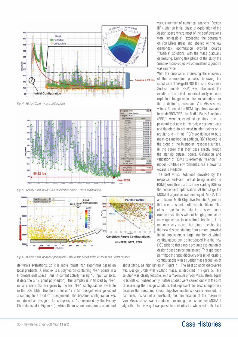
Case Histories35 - Newsletter EnginSoft Year 11 n°2
derivative evaluations, so it is more robust than algorithms based on local gradients. A simplex is a polyhedron containing N+1 points in a N dimensional space (thus in current activity having 16 input variables it describe a 17 point polyhedron). The Simplex is initialized by N+1 initial corners that are given by the first N+1 configurations available in the DOE table. Therefore a set of 17 initial designs were generated according to a random arrangement. The baseline configuration was introduced as design 0 for comparison. As described by the History Chart depicted in Figure 4 (in which the mass minimization is monitored
versus number of numerical analysis “Design ID”), after an initial phase of exploration of the design space where most of the configurations were “unfeasible” (exceeding the constraint on Von Mises stress, and labelled with yellow diamonds), optimization evolved towards “feasible” solutions, with the mass gradually decreasing. During this phase of the study the Simplex mono-objective optimization algorithm was run twice. With the purpose of increasing the efficiency of the optimization process, following the conclusion of design ID 700, the use of Response Surface models (RSM) was introduced: the results of the initial numerical analyses were exploited to generate the metamodels for the prediction of mass and Von Mises stress values. Amongst the RSM algorithms available in modeFRONTIER, the Radial Basis Functions (RBFs) were selected since they offer a powerful tool able to interpolate scattered data and therefore do not need training points on a regular grid - in fact RBFs are defined to be a meshless method. In addition, RBFs belong to the group of the interpolant response surface, in the sense that they pass exactly trough the starting dataset points. Generation and validation of RSMs is extremely “friendly” in modeFRONTIER environment since a powerful wizard is available. The best virtual solutions provided by the response surfaces (virtual being related to RSMs) were then used as a new starting DOE for the subsequent optimization. At this stage the MOGA-II algorithm was employed. MOGA-II is an efficient Multi-Objective Genetic Algorithm that uses a smart multi-search elitism. This elitism operator is able to preserve some excellent solutions without bringing premature convergence to local-optimal frontiers. It is not only very robust, but since it elaborates the new designs starting from a more crowded initial population, a larger number of virtual configurations can be introduced into the new DOE table so that a more accurate exploration of design space can be guaranteed. This approach permitted the rapid discovery of a set of feasible configurations with a sudden mass reduction of
about 20lbs, as highlighted in Figure 4. The best solution discovered was Design_3738 with 98.82lb mass, as depicted in Figure 5. This solution was clearly feasible, with a maximum of Von Mises stress equal to 63988 ksi. Subsequently, further studies were carried out with the aim of assessing the design solutions that represent the best compromise between the mass and stress objective functions (Pareto Frontier). In particular, instead of a constraint, the minimization of the maximum Von Mises stress was introduced, retaining the use of the MOGA-II algorithm. In this way it was possible to identify the whole set of the best
Fig. 4 - History Chart – mass minimization
Fig. 5 - History Chart for MOGA II optimization phase – mass minimization
Fig. 6 - Bubble Chart for multi-optimization – max of Von Mises stress vs. mass and Pareto Frontier
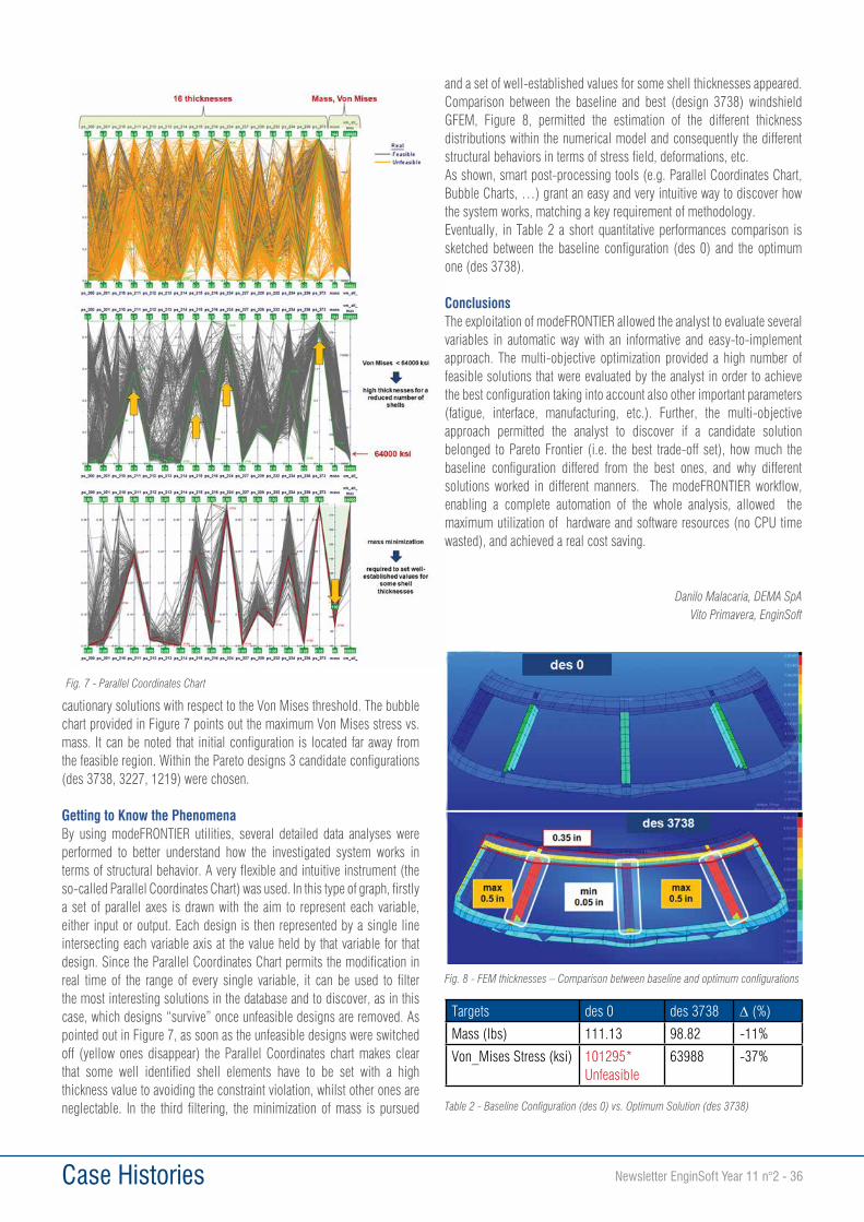
Case Histories Newsletter EnginSoft Year 11 n°2 - 36
cautionary solutions with respect to the Von Mises threshold. The bubble chart provided in Figure 7 points out the maximum Von Mises stress vs. mass. It can be noted that initial configuration is located far away from the feasible region. Within the Pareto designs 3 candidate configurations (des 3738, 3227, 1219) were chosen.
Getting to Know the Phenomena By using modeFRONTIER utilities, several detailed data analyses were performed to better understand how the investigated system works in terms of structural behavior. A very flexible and intuitive instrument (the so-called Parallel Coordinates Chart) was used. In this type of graph, firstly a set of parallel axes is drawn with the aim to represent each variable, either input or output. Each design is then represented by a single line intersecting each variable axis at the value held by that variable for that design. Since the Parallel Coordinates Chart permits the modification in real time of the range of every single variable, it can be used to filter the most interesting solutions in the database and to discover, as in this case, which designs “survive” once unfeasible designs are removed. As pointed out in Figure 7, as soon as the unfeasible designs were switched off (yellow ones disappear) the Parallel Coordinates chart makes clear that some well identified shell elements have to be set with a high thickness value to avoiding the constraint violation, whilst other ones are neglectable. In the third filtering, the minimization of mass is pursued
and a set of well-established values for some shell thicknesses appeared. Comparison between the baseline and best (design 3738) windshield GFEM, Figure 8, permitted the estimation of the different thickness distributions within the numerical model and consequently the different structural behaviors in terms of stress field, deformations, etc. As shown, smart post-processing tools (e.g. Parallel Coordinates Chart, Bubble Charts, …) grant an easy and very intuitive way to discover how the system works, matching a key requirement of methodology.Eventually, in Table 2 a short quantitative performances comparison is sketched between the baseline configuration (des 0) and the optimum one (des 3738).
ConclusionsThe exploitation of modeFRONTIER allowed the analyst to evaluate several variables in automatic way with an informative and easy-to-implement approach. The multi-objective optimization provided a high number of feasible solutions that were evaluated by the analyst in order to achieve the best configuration taking into account also other important parameters (fatigue, interface, manufacturing, etc.). Further, the multi-objective approach permitted the analyst to discover if a candidate solution belonged to Pareto Frontier (i.e. the best trade-off set), how much the baseline configuration differed from the best ones, and why different solutions worked in different manners. The modeFRONTIER workflow, enabling a complete automation of the whole analysis, allowed the maximum utilization of hardware and software resources (no CPU time wasted), and achieved a real cost saving.
Danilo Malacaria, DEMA SpAVito Primavera, EnginSoft
Fig. 7 - Parallel Coordinates Chart
Fig. 8 - FEM thicknesses – Comparison between baseline and optimum configurations
Table 2 - Baseline Configuration (des 0) vs. Optimum Solution (des 3738)
Targets des 0 des 3738 D (%)
Mass (lbs) 111.13 98.82 -11%
Von_Mises Stress (ksi) 101295* Unfeasible
63988 -37%
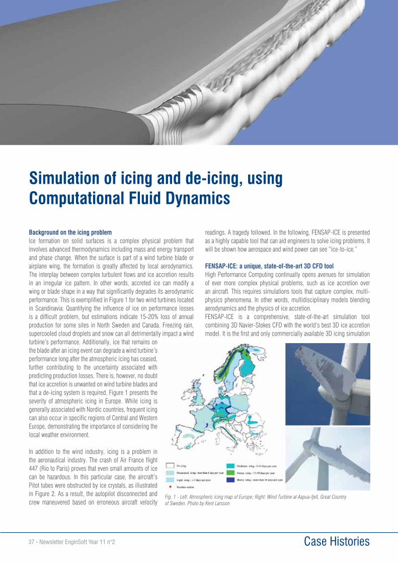
Case Histories37 - Newsletter EnginSoft Year 11 n°2
Simulation of icing and de-icing, using Computational Fluid Dynamics
Background on the icing problemIce formation on solid surfaces is a complex physical problem that involves advanced thermodynamics including mass and energy transport and phase change. When the surface is part of a wind turbine blade or airplane wing, the formation is greatly affected by local aerodynamics. The interplay between complex turbulent flows and ice accretion results in an irregular ice pattern. In other words, accreted ice can modify a wing or blade shape in a way that significantly degrades its aerodynamic performance. This is exemplified in Figure 1 for two wind turbines located in Scandinavia. Quantifying the influence of ice on performance losses is a difficult problem, but estimations indicate 15-20% loss of annual production for some sites in North Sweden and Canada. Freezing rain, supercooled cloud droplets and snow can all detrimentally impact a wind turbine’s performance. Additionally, ice that remains on the blade after an icing event can degrade a wind turbine’s performance long after the atmospheric icing has ceased, further contributing to the uncertainty associated with predicting production losses. There is, however, no doubt that ice accretion is unwanted on wind turbine blades and that a de-icing system is required. Figure 1 presents the severity of atmospheric icing in Europe. While icing is generally associated with Nordic countries, frequent icing can also occur in specific regions of Central and Western Europe, demonstrating the importance of considering the local weather environment.
In addition to the wind industry, icing is a problem in the aeronautical industry. The crash of Air France flight 447 (Rio to Paris) proves that even small amounts of ice can be hazardous. In this particular case, the aircraft’s Pitot tubes were obstructed by ice crystals, as illustrated in Figure 2. As a result, the autopilot disconnected and crew maneuvered based on erroneous aircraft velocity
readings. A tragedy followed. In the following, FENSAP-ICE is presented as a highly capable tool that can aid engineers to solve icing problems. It will be shown how aerospace and wind power can see “ice-to-ice.”
FENSAP-ICE: a unique, state-of-the-art 3D CFD toolHigh Performance Computing continually opens avenues for simulation of ever more complex physical problems, such as ice accretion over an aircraft. This requires simulations tools that capture complex, multi-physics phenomena. In other words, multidisciplinary models blending aerodynamics and the physics of ice accretion.FENSAP-ICE is a comprehensive, state-of-the-art simulation tool combining 3D Navier-Stokes CFD with the world’s best 3D ice accretion model. It is the first and only commercially available 3D icing simulation
Fig. 1 - Left: Atmospheric icing map of Europe; Right: Wind Turbine at Aapua-fjell, Great Country of Sweden. Photo by Kent Larsson
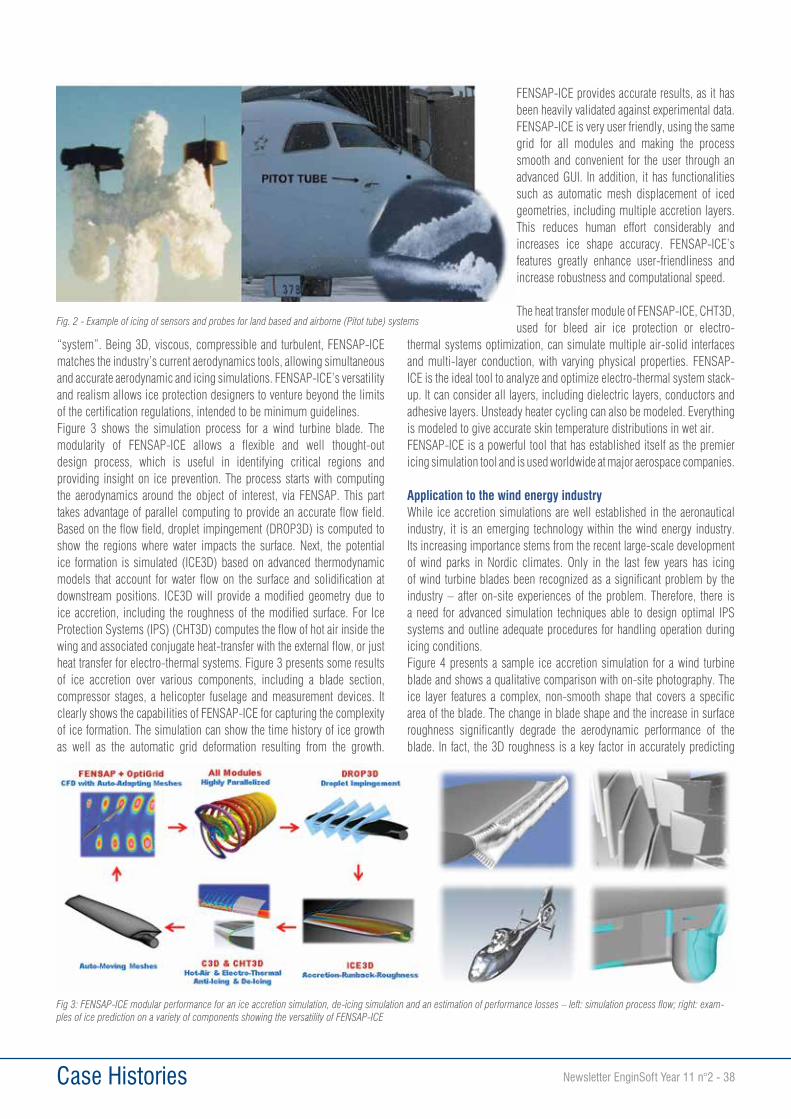
Case Histories Newsletter EnginSoft Year 11 n°2 - 38
“system”. Being 3D, viscous, compressible and turbulent, FENSAP-ICE matches the industry’s current aerodynamics tools, allowing simultaneous and accurate aerodynamic and icing simulations. FENSAP-ICE’s versatility and realism allows ice protection designers to venture beyond the limits of the certification regulations, intended to be minimum guidelines. Figure 3 shows the simulation process for a wind turbine blade. The modularity of FENSAP-ICE allows a flexible and well thought-out design process, which is useful in identifying critical regions and providing insight on ice prevention. The process starts with computing the aerodynamics around the object of interest, via FENSAP. This part takes advantage of parallel computing to provide an accurate flow field. Based on the flow field, droplet impingement (DROP3D) is computed to show the regions where water impacts the surface. Next, the potential ice formation is simulated (ICE3D) based on advanced thermodynamic models that account for water flow on the surface and solidification at downstream positions. ICE3D will provide a modified geometry due to ice accretion, including the roughness of the modified surface. For Ice Protection Systems (IPS) (CHT3D) computes the flow of hot air inside the wing and associated conjugate heat-transfer with the external flow, or just heat transfer for electro-thermal systems. Figure 3 presents some results of ice accretion over various components, including a blade section, compressor stages, a helicopter fuselage and measurement devices. It clearly shows the capabilities of FENSAP-ICE for capturing the complexity of ice formation. The simulation can show the time history of ice growth as well as the automatic grid deformation resulting from the growth.
FENSAP-ICE provides accurate results, as it has been heavily validated against experimental data.FENSAP-ICE is very user friendly, using the same grid for all modules and making the process smooth and convenient for the user through an advanced GUI. In addition, it has functionalities such as automatic mesh displacement of iced geometries, including multiple accretion layers. This reduces human effort considerably and increases ice shape accuracy. FENSAP-ICE’s features greatly enhance user-friendliness and increase robustness and computational speed.
The heat transfer module of FENSAP-ICE, CHT3D, used for bleed air ice protection or electro-
thermal systems optimization, can simulate multiple air-solid interfaces and multi-layer conduction, with varying physical properties. FENSAP-ICE is the ideal tool to analyze and optimize electro-thermal system stack-up. It can consider all layers, including dielectric layers, conductors and adhesive layers. Unsteady heater cycling can also be modeled. Everything is modeled to give accurate skin temperature distributions in wet air.FENSAP-ICE is a powerful tool that has established itself as the premier icing simulation tool and is used worldwide at major aerospace companies.
Application to the wind energy industryWhile ice accretion simulations are well established in the aeronautical industry, it is an emerging technology within the wind energy industry. Its increasing importance stems from the recent large-scale development of wind parks in Nordic climates. Only in the last few years has icing of wind turbine blades been recognized as a significant problem by the industry – after on-site experiences of the problem. Therefore, there is a need for advanced simulation techniques able to design optimal IPS systems and outline adequate procedures for handling operation during icing conditions.Figure 4 presents a sample ice accretion simulation for a wind turbine blade and shows a qualitative comparison with on-site photography. The ice layer features a complex, non-smooth shape that covers a specific area of the blade. The change in blade shape and the increase in surface roughness significantly degrade the aerodynamic performance of the blade. In fact, the 3D roughness is a key factor in accurately predicting
Fig. 2 - Example of icing of sensors and probes for land based and airborne (Pitot tube) systems
Fig 3: FENSAP-ICE modular performance for an ice accretion simulation, de-icing simulation and an estimation of performance losses – left: simulation process flow; right: exam-ples of ice prediction on a variety of components showing the versatility of FENSAP-ICE
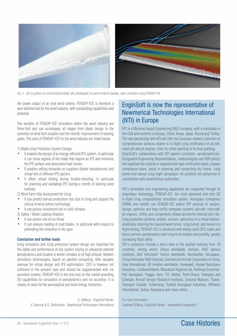
Case Histories39 - Newsletter EnginSoft Year 11 n°2
the power output of an iced wind turbine. FENSAP-ICE is therefore a well-tailored tool for the wind industry, with outstanding capabilities and potential.
The benefits of FENSAP-ICE simulation within the wind industry are three-fold and can accompany all stages from blade design to the selection of wind farm location and the retrofit/ improvement of existing parks. The uses of FENSAP-ICE for the wind industry are listed below:
1) Blade Icing Protection System Design• It enables the design of an energy-efficient IPS system, in particular
it can show regions of the blade that require an IPS and minimize the IPS surface and associated heat-losses.
• It enables setting demands on suppliers (blade manufacturer) and virtual test of different IPS options
• It offers virtual testing during trouble-shooting, in particular for planning and validating IPS during a retrofit of existing wind turbines.
2) Wind Farm Site Assessment for Icing• It can predict annual production loss due to icing and support the
choice of wind turbine technology• It can assess investment risk in cold climates3) Safety / Blade Loading Analysis• It can assess risk of ice throw• It can analyze loading of iced blades, in particular with respect to
estimating the reduction in life span
Conclusion and further leadsIcing simulation and icing protection system design are important for the safety and performance of any system relying on advanced external aerodynamics and located in winter climates or at high altitude. Modern simulation technologies, based on parallel computing, offer valuable avenues for virtual design and IPS optimization. CFD is however not sufficient in the present case and should be supplemented with ice accretion models. FENSAP-ICE is the only tool on the market providing 3D capabilities for simulation of aerodynamics and ice accretion. It is clearly of value for the aeronautical and wind energy industries.
S. Glifberg - EnginSoft NordicV. Soumoy & D. Switchenko - Newmerical Technologies International
Fig. 4 - 3D ice pattern on a wind turbine blade, left: photograph of a wind in North Sweden, right: simulation using FENSAP-ICE
NTI is a Montreal-based Engineering R&D company, with a subsidiary in the USA and resellers in Europe, China, Korea, Japan, Russia and Turkey.The new partnership with NTI will offer the European market a selection of comprehensive services related to in-flight icing certification of aircraft, rotorcraft and jet engines, from its initial planning to its final granting. EnginSoft’s collaboration with NTI experts (scientists, aerodynamicists, Designated Engineering Representatives, meteorologists and DER-pilots) will negotiate the original or supplemental type certification basis, prepare compliance plans, assist in planning and conducting dry tunnel, icing tunnel and natural icing flight campaigns. All activities are performed in coordination with airworthiness authorities.
NTI’s simulation and engineering capabilities are supported through its proprietary technology, FENSAP-ICE, the most advanced and only 3D in-flight icing computational simulation system. Aerospace companies (OEMs and retrofit) use FENSAP-ICE and/or NTI services to analyze, design, optimize and help certify complete systems (aircraft, rotorcraft, jet engines, UAVs) and components (bleed-air/electro-thermal anti-/de-icing protection systems, probes, sensors, optronics) in a virtual fashion, drastically reducing the required wind tunnel, icing tunnel, and natural ice flight-testing. FENSAP-ICE is interfaced with widely used CFD codes and hence permits aerodynamics and icing to be treated concurrently, greatly increasing flight safety.NTI’s customers include a who’s-who of the aviation industry from 18 countries, among which: Airbus worldwide, Aselsan, AVIC various institutes, Bell Helicopter Textron worldwide, Bombardier Aerospace, China Helicopter R&D Institute, Commercial Aircraft Corporation of China, Dow International, GE Aviation worldwide, Honeywell, Korean Aerospace Industries, Lockheed Martin, Mitsubishi Regional Jet, Northrop Grumman, Pall Aerospace, Piaggio Aero, PZL Mielec, Rolls-Royce, Shanghai and Chengdu Aircraft Design Research Institutes, Snecma Moteurs, Thales, Transport Canada, Turbomeca, Turkish Aerospace Industries, Williams International, Zodiac Aerospace and many others.
For more information: Susanne Glifberg, EnginSoft Nordic - [email protected]
EnginSoft is now the representative of Newmerical Technologies International (NTI) in Europe
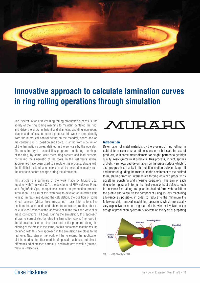
Case Histories Newsletter EnginSoft Year 11 n°2 - 40
The “secret” of an efficient Ring rolling production process is the ability of the ring rolling machine to maintain centered the ring, and drive the grow in height and diameter, avoiding non-round shapes and defects. In the real process, this work is done directly from the numerical control acting on the mandrel, cones and on the centering rolls (position and Force), starting from a definition of the lamination curves, defined in the software by the operator. The machine try to respect this program, monitoring the shape of the ring, by some laser measuring system and load sensors, correcting the kinematic of the tools. In the last years several approaches have been used to simulate this process, always with the limit that the lamination curves must be inserted manually from the user and cannot change during the simulation.
This article is a summary of the work made by Muraro Spa, together with Transvalor S.A., the developer of FEM software Forge and EnginSoft Spa, competence center on production process simulation. The aim of this work was to develop an interface able to read, in real-time during the calculation, the position of some virtual sensors (virtual laser measuring), pass informations like position, but also loads and others, to an external routine, able to calculate corrections of the kinematic of all the tools and write back these corrections in Forge. During the simulation, this approach allows to correct step-by-step the lamination curve. The logic in the simulation external black-box and in the program driving the piloting of the press is the same, so this guarantees that the results obtained with this new approach in the simulation are close to the real one. Next step of the work will be to extend the application of this interface to other models of special machines, but also to different kind of presses normally used to deform metallic (an non-metallic) materials.
IntroductionDeformation of metal materials by the process of ring rolling, in cold state in case of small dimensions or in hot state in case of products, with some meter diameter or height, permits to get high quality axial-symmetrical products. This process, in fact, applies a slight, very localized deformation on the piece surface which is also progressive, thanks to the rotation motion between king roll and mandrel, guiding the material to the obtainment of the desired form, starting from an intermediate forging obtained properly by upsetting, punching and shearing operations. The aim of each ring roller operator is to get the final piece without defects, such for instance fish-tailing, to upset the desired form with no fail on the profile and to realize the component using as less machining allowance as possible, in order to reduce to the minimum the following chip removal machining operations which are usually very expensive. In order to get all of this, who is involved in the design of production cycles must operate on the cycle of preparing
Innovative approach to calculate lamination curves in ring rolling operations through simulation
Fig. 1 - Ring-rolling process
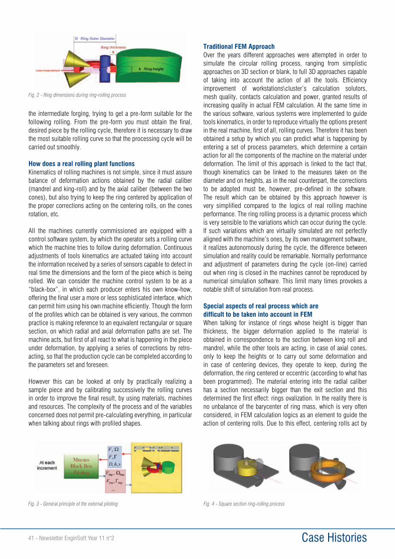
Case Histories41 - Newsletter EnginSoft Year 11 n°2
the intermediate forging, trying to get a pre-form suitable for the following rolling. From the pre-form you must obtain the final, desired piece by the rolling cycle, therefore it is necessary to draw the most suitable rolling curve so that the processing cycle will be carried out smoothly.
How does a real rolling plant functionsKinematics of rolling machines is not simple, since it must assure balance of deformation actions obtained by the radial caliber (mandrel and king-roll) and by the axial caliber (between the two cones), but also trying to keep the ring centered by application of the proper corrections acting on the centering rolls, on the cones rotation, etc.
All the machines currently commissioned are equipped with a control software system, by which the operator sets a rolling curve which the machine tries to follow during deformation. Continuous adjustments of tools kinematics are actuated taking into account the information received by a series of sensors capable to detect in real time the dimensions and the form of the piece which is being rolled. We can consider the machine control system to be as a “black-box”, in which each producer enters his own know-how, offering the final user a more or less sophisticated interface, which can permit him using his own machine efficiently. Though the form of the profiles which can be obtained is very various, the common practice is making reference to an equivalent rectangular or square section, on which radial and axial deformation paths are set. The machine acts, but first of all react to what is happening in the piece under deformation, by applying a series of corrections by retro-acting, so that the production cycle can be completed according to the parameters set and foreseen.
However this can be looked at only by practically realizing a sample piece and by calibrating successively the rolling curves in order to improve the final result, by using materials, machines and resources. The complexity of the process and of the variables concerned does not permit pre-calculating everything, in particular when talking about rings with profiled shapes.
Traditional FEM ApproachOver the years different approaches were attempted in order to simulate the circular rolling process, ranging from simplistic approaches on 3D section or blank, to full 3D approaches capable of taking into account the action of all the tools. Efficiency improvement of workstations\cluster’s calculation solutors, mesh quality, contacts calculation and power, granted results of increasing quality in actual FEM calculation. At the same time in the various software, various systems were implemented to guide tools kinematics, in order to reproduce virtually the options present in the real machine, first of all, rolling curves. Therefore it has been obtained a setup by which you can predict what is happening by entering a set of process parameters, which determine a certain action for all the components of the machine on the material under deformation. The limit of this approach is linked to the fact that, though kinematics can be linked to the measures taken on the diameter and on heights, as in the real counterpart, the corrections to be adopted must be, however, pre-defined in the software. The result which can be obtained by this approach however is very simplified compared to the logics of real rolling machine performance. The ring rolling process is a dynamic process which is very sensible to the variations which can occur during the cycle. If such variations which are virtually simulated are not perfectly aligned with the machine’s ones, by its own management software, it realizes autonomously during the cycle, the difference between simulation and reality could be remarkable. Normally performance and adjustment of parameters during the cycle (on-line) carried out when ring is closed in the machines cannot be reproduced by numerical simulation software. This limit many times provokes a notable shift of simulation from real process.
Special aspects of real process which are difficult to be taken into account in FEMWhen talking for instance of rings whose height is bigger than thickness, the bigger deformation applied to the material is obtained in correspondence to the section between king roll and mandrel, while the other tools are acting, in case of axial cones, only to keep the heights or to carry out some deformation and in case of centering devices, they operate to keep, during the deformation, the ring centered or eccentric (according to what has been programmed). The material entering into the radial caliber has a section necessarily bigger than the exit section and this determined the first effect: rings ovalization. In the reality there is no unbalance of the barycenter of ring mass, which is very often considered, in FEM calculation logics as an element to guide the action of centering rolls. Due to this effect, centering rolls act by
Fig. 2 - Ring dimensions during ring-rolling process
Fig. 3 - General principle of the external piloting Fig. 4 - Square section ring-rolling process

Case Histories Newsletter EnginSoft Year 11 n°2 - 42
kinematics different from real machines which do not take into consideration in command logics the ring’s center of gravity, as a consequence also the centering forces result to have been altered compared to reality. Actually, in the most sophisticated machines, control logics of centering devices can foresee the type of performance by force or position control, by a passage between the two conditions depending from the contact situation detected instant by instant. These effects can be neglected when rolling rings with simple rectangular sections, but become fundamental when rolling section shaped internally and/or externally.
For the last ones, in fact, the machine permits to set a rolling voluntarily out-of-center, depending from the diameter so that the material gets in touch more with the profile of the king rolling or with the external profile of the mandrel. In order to do this the management integrated between centering devices and axial cones rotation is fundamental. Such cones must have a vertical motion capable to control the growth of the ring in the axial direction, in this case too, by curves of suitable kinematics. To complete this picture, it must be taken into account that in each machine there are some mechanic and hydraulic inertias the machine tries to react to, by some corrective actions of kinematics balance. It appears quite evident by now how interlacing and overlapping of these effects must be considered as fundamental in software system on board machine, where is located the “secret” for the proper performance of the machine.
Innovative ApproachMuraro SpA is a constructor of presses and complete plants, its site is at Zermeghedo (VI) and chose the software FEM Transvalor Forge, with installation on calculation cluster having an elevated number of cores. The first activities performed by the software FEM, with the support of Enginsoft SpA, center of competence for the simulation of the productive processes, highlighted the limits described above and pushed the exploration of a new approach to process modeling. It has been supposed to rank the instrument FEM as the rolling plant “engine” and it has been developed externally the “control logics”, based upon the concepts applied on board machine to guide the tools motions. The software FEM has been equipped
with the same intelligence which has been programmed on the real machine. It has been set out then a cooperation with the company producing the software, Transvalor S.A, which permitted to open the software to bi-directional communication by this external instrument playing as the
“black-box” cited above. The program developed by Muraro, in this phase of continuous evolution due to the result obtained by its utilization, has a user interface reproducing exactly the operations that the operator must carry out on board machine, permitting to set the rolling curve, i.e. the relation between height/thickness and the time and the process starting parameters. It has been foreseen, as in the real machine, the possibility to change “in time” the rolling data also during the simulation calculation.
The FEM model to be set in the program Forge, instead, is standard and requires only introduction of tools geometries, in the format stl or step, while the kinematic definition foresees the only setting of the proper rotation axes of all the objects and does not require any operator’s intervention in the definition of the motion a/o speeds rules, this is carried out automatically by the “Black box”. Once the preparatory phase has been completed the simulation is carried out and from this moment on the two instruments, Forge simulation software and the program developed by Muraro, interacting starts, by exchanging information about the position of tools, ring’s characteristics (ovality, external dimensions, ring’s out-of-center, forces on the mandrel, cones and centering rolls, etc. The innovation aspect of this approach is the modality by which the external instrument acts, adopting the same calculation logics and the same correction instruments that the software on board machine uses to modify the position and actions of tools on the ring under deformation, reacting in this way to what is happening during the deformation. Such exchange of information is carried out very frequently and therefore the system can “see” also the peak effects linked to unforeseen (or voluntary) shifts of the ring or to inertia effects linked to the movement of the parts concerned.
Fig. 5 - Example of piloting function
Fig. 6 - Shaped sections: Ring-rolling examples
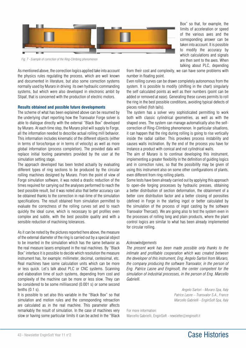
Case Histories43 - Newsletter EnginSoft Year 11 n°2
As mentioned above, the correction logics applied take into account the physics rules regulating the process, which are well known and documented in literature, but also some correction systems normally used by Muraro in driving its own hydraulic commanding systems, but which were also developed in electronic ambit by Stipaf, that is concerned with the production of electric motors.
Results obtained and possible future developmentsThe scheme of what has been explained above can be resumed by the underlying chart reporting how the Transvalor Forge solver is able to dialogue directly with the external “Black Box” developed by Muraro. At each time step, the Muraro pilot will supply to Forge, all the information needed to describe actual rolling mill behavior. This information includes kinematic of the different objects (either in terms of force/torque or in terms of velocity) as well as more global information (process completion). The provided data will replace initial tooling parameters provided by the user at the simulation setting stage.The approach developed has been tested actually by evaluating different types of ring sections to be produced by the circular rolling machines designed by Muraro. From the point of view of Forge simulation software, it was noted a drastic reduction of the times required for carrying out the analyses performed to reach the best possible result, but it was noted also that better accuracy can be obtained thanks to the correction in real-time of the simulation specifications. The result obtained from simulation permitted to evaluate the correctness of the rolling curves set and to reach quickly the ideal curve, which is necessary to get profiles even complex and subtle, with the best possible quality and with a sensible reduction of machining tolerances.
As it can be noted by the pictures reported here above, the measure of the external diameter of the ring is carried out by a special object to be inserted in the simulation which has the same behavior as the real measure lasers employed in the real machines. By “Black Box” interface it is possible to decide which resolution the measure instrument has, for example: millimeter, decimal, centesimal, etc. Real machines have some calculation units which can be more or less quick. Let’s talk about PLC or CNC systems. Scanning and elaboration time of such systems, depending from cost and complexity of the machine can be more or less slow. They can be considered to be some millisecond (0.001 s) or some second tenths (0.1 s).It is possible to set also this variable in the “Black Box” so that simulation and motion rules and the corresponding retroaction are calculated as in the real machine. This parameter affects remarkably the result of simulation. In the case of machines very slow or having some particular limits it can be acted in the “Black
Box” so that, for example, the limits of acceleration or speed of the various axes and the corresponding answer can be taken into account. It is possible to modify the accuracy by which calculations and signals are then sent to the axes. When talking about PLC, depending
from their cost and complexity, we can have some problems with number in floating point.Even rolling curves can be drawn completely autonomous from the system. It is possible to modify (shifting in the chart) singularly the self calculated points as well as their numbers (point can be added or removed at ease). Generating these curves permits to roll the ring in the best possible conditions, avoiding typical defects of pieces rolled (fish tails).The system has a solver very sophisticated permitting to work both with classic cylindrical geometries, as well as with the shaped ones. The system can manage automatically also the self-correction of Ring-Climbing phenomenon. In particular situations, it can happen that the ring during rolling is going to rise vertically inside the radial caliber. This provokes process instability and causes walls inclination. By the end of the process you have for instance a product with conical and not cylindrical walls. The aim of Muraro is to continue developing this instrument, implementing a greater flexibility in the definition of guiding logics and in correction rules, so that the possibility may be given of using this instrument also on some other configurations of plants, even different from ring rolling plants. Some tests have been already carried out by applying this approach to open-die forging processes by hydraulic presses, obtaining a better distribution of section deformation, the obtainment of a better core distribution factor and a better closing of porosities (defined in Forge in the starting ingot or better calculated by the simulation of the process of ingot casting by the software Transvalor Thercast). We are going also to test the system even in the processes of rolling long and plain products, where the plant control logics are similar to what has been already implemented for circular rolling.
Acknowledgements The present work has been made possible only thanks to the intimate and profitable cooperation which was created between the developer of this instrument, Eng. Angelo Sartori from Muraro, the company producing the software Transvalor, in the person of Eng. Patrice Lasne and Enginsoft, the center competent for the simulation of industrial processes, in the person of Eng. Marcello Gabrielli.
Angelo Sartori - Muraro Spa, ItalyPatrice Lasne – Transvalor S.A., FranceMarcello Gabrielli - EnginSoft Spa, Italy
For more information: Marcello Gabrielli, EnginSoft - [email protected]
Fig. 7 - Example of correction of the Ring-Climbing phenomenon
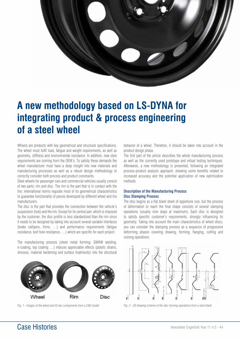
Case Histories Newsletter EnginSoft Year 11 n°2 - 44
Wheels are products with key geometrical and structural specifications. The wheel must fulfil load, fatigue and weight requirements, as well as geometry, stiffness and environmental resistance. In addition, new style requirements are coming from the OEM’s. To satisfy these demands the wheel manufacturer must have a deep insight into new materials and manufacturing processes as well as a robust design methodology to correctly consider both process and product constraints.Steel wheels for passenger cars and commercial vehicles usually consist of two parts: rim and disc. The rim is the part that is in contact with the tire: international norms regulate most of its geometrical characteristics to guarantee functionality of pieces developed by different wheel and tire manufacturers.The disc is the part that provides the connection between the vehicle’s suspension (hub) and the rim. Except for its central part, which is imposed by the customer, the disc profile is less standardized than the rim since it needs to be designed by taking into account several variable interfaces (brake callipers, trims, …) and performance requirements (fatigue resistance, bolt hole resistance, …) which are specific for each project.
The manufacturing process (sheet metal forming, GMAW welding, e-coating, top coating …) induces appreciable effects (plastic strains, stresses, material hardening and surface treatments) into the structural
behavior of a wheel. Therefore, it should be taken into account in the product design phase.The first part of the article describes the whole manufacturing process as well as the currently used prototype and virtual testing techniques. Afterwards, a new methodology is presented, following an integrated process-product analysis approach, showing some benefits related to increased accuracy and the potential application of new optimization methods.
Description of the Manufacturing ProcessDisc Stamping ProcessThe disc begins as a flat blank sheet of opportune size, but the process of deformation to reach the final shape consists of several stamping operations (usually nine steps at maximum). Each disc is designed to satisfy specific customer’s requirements, strongly influencing its geometry. Taking into account the main characteristics of wheel discs, you can consider the stamping process as a sequence of progressive deforming phases covering drawing, forming, flanging, cutting and coining operations.
A new methodology based on LS-DYNA for integrating product & process engineering of a steel wheel
Fig. 1 - Images of the wheel and its two components from a CAD model Fig. 2 - 2D drawing scheme of the disc forming operations from a steel blank
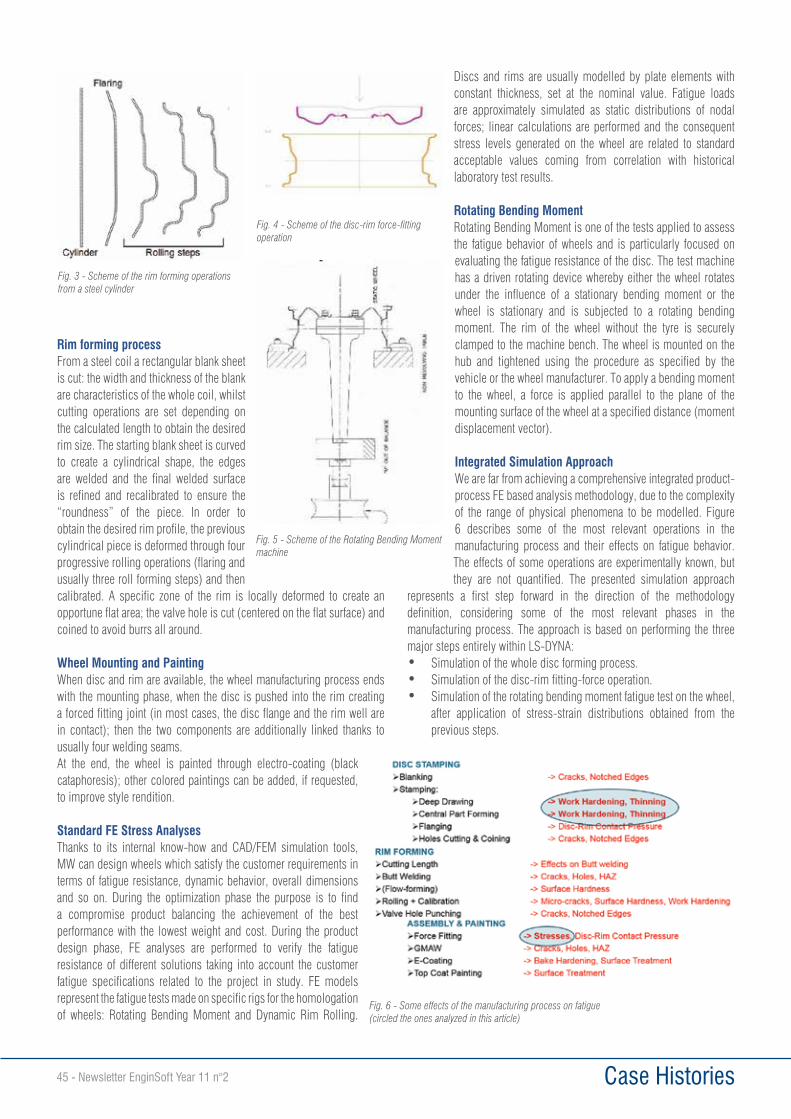
Case Histories45 - Newsletter EnginSoft Year 11 n°2
Rim forming processFrom a steel coil a rectangular blank sheet is cut: the width and thickness of the blank are characteristics of the whole coil, whilst cutting operations are set depending on the calculated length to obtain the desired rim size. The starting blank sheet is curved to create a cylindrical shape, the edges are welded and the final welded surface is refined and recalibrated to ensure the “roundness” of the piece. In order to obtain the desired rim profile, the previous cylindrical piece is deformed through four progressive rolling operations (flaring and usually three roll forming steps) and then calibrated. A specific zone of the rim is locally deformed to create an opportune flat area; the valve hole is cut (centered on the flat surface) and coined to avoid burrs all around.
Wheel Mounting and PaintingWhen disc and rim are available, the wheel manufacturing process ends with the mounting phase, when the disc is pushed into the rim creating a forced fitting joint (in most cases, the disc flange and the rim well are in contact); then the two components are additionally linked thanks to usually four welding seams.At the end, the wheel is painted through electro-coating (black cataphoresis); other colored paintings can be added, if requested, to improve style rendition.
Standard FE Stress AnalysesThanks to its internal know-how and CAD/FEM simulation tools, MW can design wheels which satisfy the customer requirements in terms of fatigue resistance, dynamic behavior, overall dimensions and so on. During the optimization phase the purpose is to find a compromise product balancing the achievement of the best performance with the lowest weight and cost. During the product design phase, FE analyses are performed to verify the fatigue resistance of different solutions taking into account the customer fatigue specifications related to the project in study. FE models represent the fatigue tests made on specific rigs for the homologation of wheels: Rotating Bending Moment and Dynamic Rim Rolling.
Discs and rims are usually modelled by plate elements with constant thickness, set at the nominal value. Fatigue loads are approximately simulated as static distributions of nodal forces; linear calculations are performed and the consequent stress levels generated on the wheel are related to standard acceptable values coming from correlation with historical laboratory test results.
Rotating Bending MomentRotating Bending Moment is one of the tests applied to assess the fatigue behavior of wheels and is particularly focused on evaluating the fatigue resistance of the disc. The test machine has a driven rotating device whereby either the wheel rotates under the influence of a stationary bending moment or the wheel is stationary and is subjected to a rotating bending moment. The rim of the wheel without the tyre is securely clamped to the machine bench. The wheel is mounted on the hub and tightened using the procedure as specified by the vehicle or the wheel manufacturer. To apply a bending moment to the wheel, a force is applied parallel to the plane of the mounting surface of the wheel at a specified distance (moment displacement vector).
Integrated Simulation ApproachWe are far from achieving a comprehensive integrated product-process FE based analysis methodology, due to the complexity of the range of physical phenomena to be modelled. Figure 6 describes some of the most relevant operations in the manufacturing process and their effects on fatigue behavior. The effects of some operations are experimentally known, but they are not quantified. The presented simulation approach
represents a first step forward in the direction of the methodology definition, considering some of the most relevant phases in the manufacturing process. The approach is based on performing the three major steps entirely within LS-DYNA:• Simulation of the whole disc forming process.• Simulation of the disc-rim fitting-force operation.• Simulation of the rotating bending moment fatigue test on the wheel,
after application of stress-strain distributions obtained from the previous steps.
Fig. 3 - Scheme of the rim forming operations from a steel cylinder
Fig. 4 - Scheme of the disc-rim force-fitting operation
Fig. 5 - Scheme of the Rotating Bending Moment machine
Fig. 6 - Some effects of the manufacturing process on fatigue (circled the ones analyzed in this article)
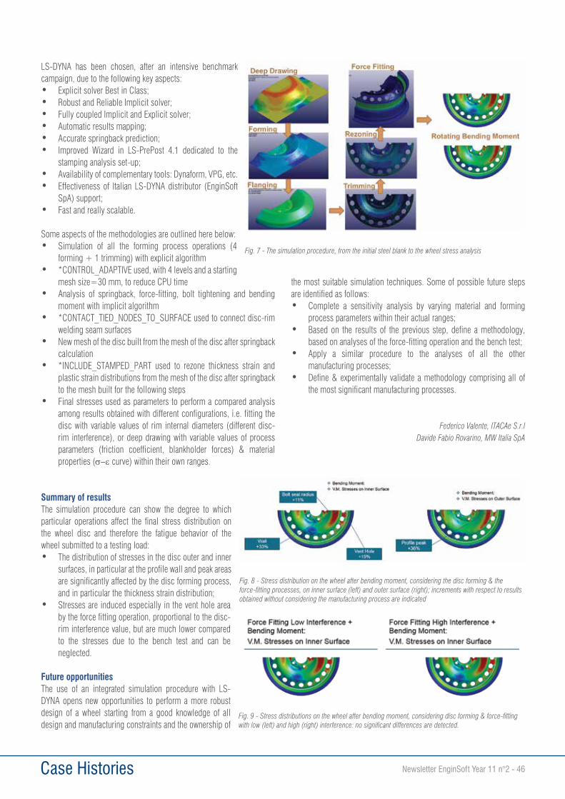
Case Histories Newsletter EnginSoft Year 11 n°2 - 46
LS-DYNA has been chosen, after an intensive benchmark campaign, due to the following key aspects:• Explicit solver Best in Class;• Robust and Reliable Implicit solver;• Fully coupled Implicit and Explicit solver;• Automatic results mapping;• Accurate springback prediction;• Improved Wizard in LS-PrePost 4.1 dedicated to the
stamping analysis set-up;• Availability of complementary tools: Dynaform, VPG, etc.• Effectiveness of Italian LS-DYNA distributor (EnginSoft
SpA) support;• Fast and really scalable.
Some aspects of the methodologies are outlined here below:• Simulation of all the forming process operations (4
forming + 1 trimming) with explicit algorithm• *CONTROL_ADAPTIVE used, with 4 levels and a starting
mesh size=30 mm, to reduce CPU time• Analysis of springback, force-fitting, bolt tightening and bending
moment with implicit algorithm• *CONTACT_TIED_NODES_TO_SURFACE used to connect disc-rim
welding seam surfaces• New mesh of the disc built from the mesh of the disc after springback
calculation• *INCLUDE_STAMPED_PART used to rezone thickness strain and
plastic strain distributions from the mesh of the disc after springback to the mesh built for the following steps
• Final stresses used as parameters to perform a compared analysis among results obtained with different configurations, i.e. fitting the disc with variable values of rim internal diameters (different disc-rim interference), or deep drawing with variable values of process parameters (friction coefficient, blankholder forces) & material properties (s-ε curve) within their own ranges.
Summary of resultsThe simulation procedure can show the degree to which particular operations affect the final stress distribution on the wheel disc and therefore the fatigue behavior of the wheel submitted to a testing load:• The distribution of stresses in the disc outer and inner
surfaces, in particular at the profile wall and peak areas are significantly affected by the disc forming process, and in particular the thickness strain distribution;
• Stresses are induced especially in the vent hole area by the force fitting operation, proportional to the disc-rim interference value, but are much lower compared to the stresses due to the bench test and can be neglected.
Future opportunitiesThe use of an integrated simulation procedure with LS-DYNA opens new opportunities to perform a more robust design of a wheel starting from a good knowledge of all design and manufacturing constraints and the ownership of
the most suitable simulation techniques. Some of possible future steps are identified as follows:• Complete a sensitivity analysis by varying material and forming
process parameters within their actual ranges;• Based on the results of the previous step, define a methodology,
based on analyses of the force-fitting operation and the bench test;• Apply a similar procedure to the analyses of all the other
manufacturing processes;• Define & experimentally validate a methodology comprising all of
the most significant manufacturing processes.
Federico Valente, ITACAe S.r.lDavide Fabio Rovarino, MW Italia SpA
Fig. 7 - The simulation procedure, from the initial steel blank to the wheel stress analysis
Fig. 9 - Stress distributions on the wheel after bending moment, considering disc forming & force-fitting with low (left) and high (right) interference: no significant differences are detected.
Fig. 8 - Stress distribution on the wheel after bending moment, considering the disc forming & the force-fitting processes, on inner surface (left) and outer surface (right); increments with respect to results obtained without considering the manufacturing process are indicated
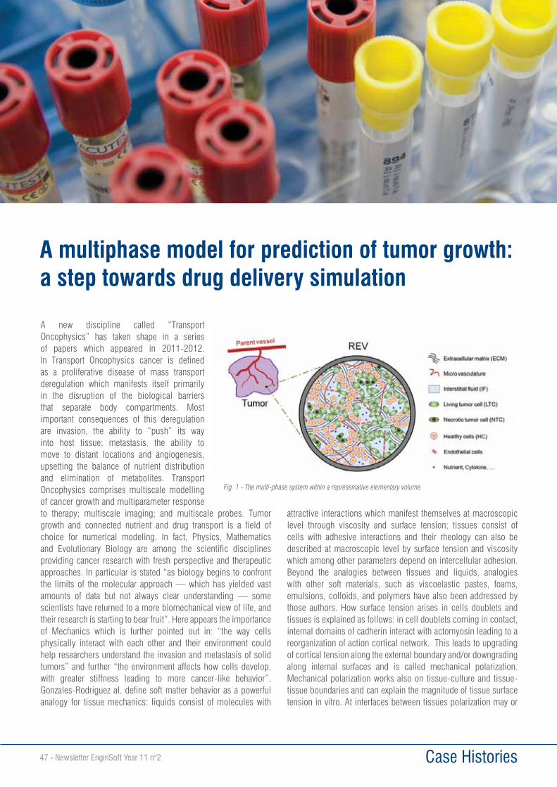
Case Histories47 - Newsletter EnginSoft Year 11 n°2
A new discipline called “Transport Oncophysics” has taken shape in a series of papers which appeared in 2011-2012. In Transport Oncophysics cancer is defined as a proliferative disease of mass transport deregulation which manifests itself primarily in the disruption of the biological barriers that separate body compartments. Most important consequences of this deregulation are invasion, the ability to “push” its way into host tissue; metastasis, the ability to move to distant locations and angiogenesis, upsetting the balance of nutrient distribution and elimination of metabolites. Transport Oncophysics comprises multiscale modelling of cancer growth and multiparameter response to therapy; multiscale imaging; and multiscale probes. Tumor growth and connected nutrient and drug transport is a field of choice for numerical modeling. In fact, Physics, Mathematics and Evolutionary Biology are among the scientific disciplines providing cancer research with fresh perspective and therapeutic approaches. In particular is stated “as biology begins to confront the limits of the molecular approach — which has yielded vast amounts of data but not always clear understanding — some scientists have returned to a more biomechanical view of life, and their research is starting to bear fruit”. Here appears the importance of Mechanics which is further pointed out in: “the way cells physically interact with each other and their environment could help researchers understand the invasion and metastasis of solid tumors” and further “the environment affects how cells develop, with greater stiffness leading to more cancer-like behavior”. Gonzales-Rodriguez al. define soft matter behavior as a powerful analogy for tissue mechanics: liquids consist of molecules with
attractive interactions which manifest themselves at macroscopic level through viscosity and surface tension; tissues consist of cells with adhesive interactions and their rheology can also be described at macroscopic level by surface tension and viscosity which among other parameters depend on intercellular adhesion. Beyond the analogies between tissues and liquids, analogies with other soft materials, such as viscoelastic pastes, foams, emulsions, colloids, and polymers have also been addressed by those authors. How surface tension arises in cells doublets and tissues is explained as follows: in cell doublets coming in contact, internal domains of cadherin interact with actomyosin leading to a reorganization of action cortical network. This leads to upgrading of cortical tension along the external boundary and/or downgrading along internal surfaces and is called mechanical polarization. Mechanical polarization works also on tissue-culture and tissue-tissue boundaries and can explain the magnitude of tissue surface tension in vitro. At interfaces between tissues polarization may or
A multiphase model for prediction of tumor growth: a step towards drug delivery simulation
Fig. 1 - The multi-phase system within a representative elementary volume
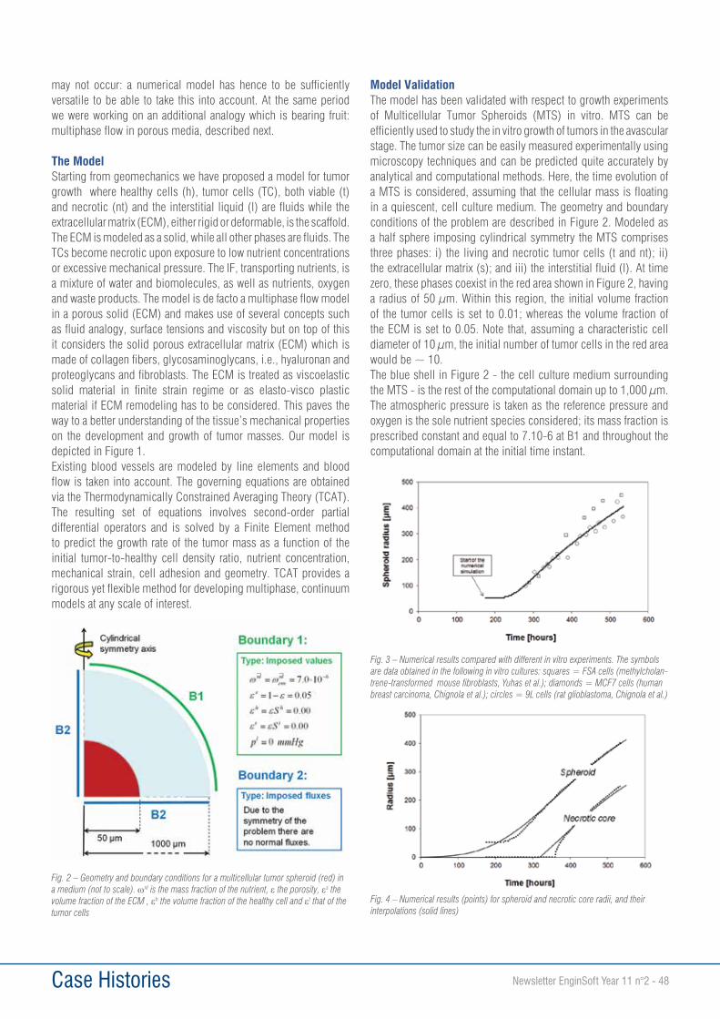
Case Histories Newsletter EnginSoft Year 11 n°2 - 48
may not occur: a numerical model has hence to be sufficiently versatile to be able to take this into account. At the same period we were working on an additional analogy which is bearing fruit: multiphase flow in porous media, described next.
The ModelStarting from geomechanics we have proposed a model for tumor growth where healthy cells (h), tumor cells (TC), both viable (t) and necrotic (nt) and the interstitial liquid (l) are fluids while the extracellular matrix (ECM), either rigid or deformable, is the scaffold. The ECM is modeled as a solid, while all other phases are fluids. The TCs become necrotic upon exposure to low nutrient concentrations or excessive mechanical pressure. The IF, transporting nutrients, is a mixture of water and biomolecules, as well as nutrients, oxygen and waste products. The model is de facto a multiphase flow model in a porous solid (ECM) and makes use of several concepts such as fluid analogy, surface tensions and viscosity but on top of this it considers the solid porous extracellular matrix (ECM) which is made of collagen fibers, glycosaminoglycans, i.e., hyaluronan and proteoglycans and fibroblasts. The ECM is treated as viscoelastic solid material in finite strain regime or as elasto-visco plastic material if ECM remodeling has to be considered. This paves the way to a better understanding of the tissue’s mechanical properties on the development and growth of tumor masses. Our model is depicted in Figure 1. Existing blood vessels are modeled by line elements and blood flow is taken into account. The governing equations are obtained via the Thermodynamically Constrained Averaging Theory (TCAT). The resulting set of equations involves second-order partial differential operators and is solved by a Finite Element method to predict the growth rate of the tumor mass as a function of the initial tumor-to-healthy cell density ratio, nutrient concentration, mechanical strain, cell adhesion and geometry. TCAT provides a rigorous yet flexible method for developing multiphase, continuum models at any scale of interest.
Model ValidationThe model has been validated with respect to growth experiments of Multicellular Tumor Spheroids (MTS) in vitro. MTS can be efficiently used to study the in vitro growth of tumors in the avascular stage. The tumor size can be easily measured experimentally using microscopy techniques and can be predicted quite accurately by analytical and computational methods. Here, the time evolution of a MTS is considered, assuming that the cellular mass is floating in a quiescent, cell culture medium. The geometry and boundary conditions of the problem are described in Figure 2. Modeled as a half sphere imposing cylindrical symmetry the MTS comprises three phases: i) the living and necrotic tumor cells (t and nt); ii) the extracellular matrix (s); and iii) the interstitial fluid (l). At time zero, these phases coexist in the red area shown in Figure 2, having a radius of 50 μm. Within this region, the initial volume fraction of the tumor cells is set to 0.01; whereas the volume fraction of the ECM is set to 0.05. Note that, assuming a characteristic cell diameter of 10 μm, the initial number of tumor cells in the red area would be ~ 10. The blue shell in Figure 2 - the cell culture medium surrounding the MTS - is the rest of the computational domain up to 1,000 μm. The atmospheric pressure is taken as the reference pressure and oxygen is the sole nutrient species considered; its mass fraction is prescribed constant and equal to 7.10-6 at B1 and throughout the computational domain at the initial time instant.
Fig. 2 – Geometry and boundary conditions for a multicellular tumor spheroid (red) in a medium (not to scale). ωnl is the mass fraction of the nutrient, ε the porosity, εs the volume fraction of the ECM , εh the volume fraction of the healthy cell and εt that of the tumor cells
Fig. 3 – Numerical results compared with different in vitro experiments. The symbols are data obtained in the following in vitro cultures: squares = FSA cells (methylcholan-trene-transformed mouse fibroblasts, Yuhas et al.); diamonds = MCF7 cells (human breast carcinoma, Chignola et al.); circles = 9L cells (rat glioblastoma, Chignola et al.)
Fig. 4 – Numerical results (points) for spheroid and necrotic core radii, and their interpolations (solid lines)
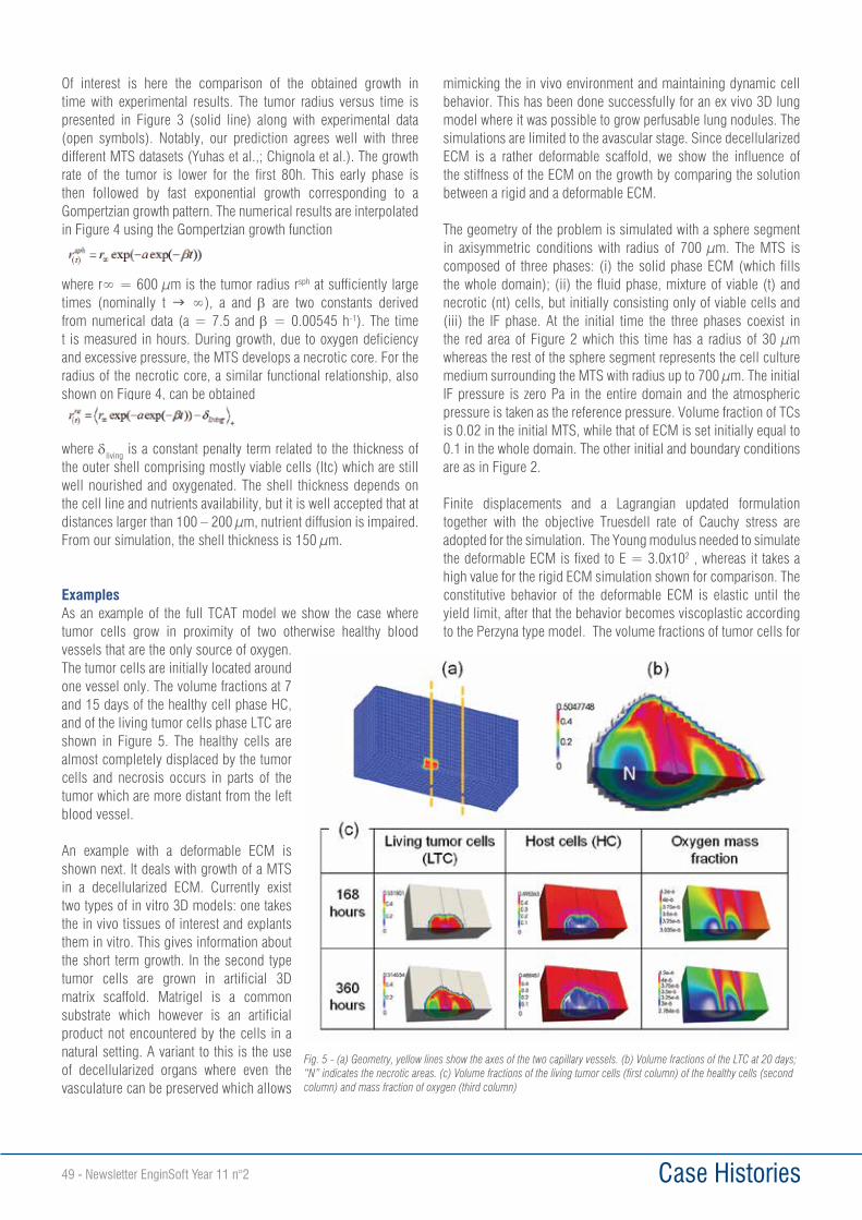
Case Histories49 - Newsletter EnginSoft Year 11 n°2
Of interest is here the comparison of the obtained growth in time with experimental results. The tumor radius versus time is presented in Figure 3 (solid line) along with experimental data (open symbols). Notably, our prediction agrees well with three different MTS datasets (Yuhas et al.,; Chignola et al.). The growth rate of the tumor is lower for the first 80h. This early phase is then followed by fast exponential growth corresponding to a Gompertzian growth pattern. The numerical results are interpolated in Figure 4 using the Gompertzian growth function
where r∞ = 600 μm is the tumor radius rsph at sufficiently large times (nominally t g ∞), a and β are two constants derived from numerical data (a = 7.5 and β = 0.00545 h-1). The time t is measured in hours. During growth, due to oxygen deficiency and excessive pressure, the MTS develops a necrotic core. For the radius of the necrotic core, a similar functional relationship, also shown on Figure 4, can be obtained
where dliving is a constant penalty term related to the thickness of the outer shell comprising mostly viable cells (ltc) which are still well nourished and oxygenated. The shell thickness depends on the cell line and nutrients availability, but it is well accepted that at distances larger than 100 – 200 μm, nutrient diffusion is impaired. From our simulation, the shell thickness is 150 μm.
ExamplesAs an example of the full TCAT model we show the case where tumor cells grow in proximity of two otherwise healthy blood vessels that are the only source of oxygen. The tumor cells are initially located around one vessel only. The volume fractions at 7 and 15 days of the healthy cell phase HC, and of the living tumor cells phase LTC are shown in Figure 5. The healthy cells are almost completely displaced by the tumor cells and necrosis occurs in parts of the tumor which are more distant from the left blood vessel.
An example with a deformable ECM is shown next. It deals with growth of a MTS in a decellularized ECM. Currently exist two types of in vitro 3D models: one takes the in vivo tissues of interest and explants them in vitro. This gives information about the short term growth. In the second type tumor cells are grown in artificial 3D matrix scaffold. Matrigel is a common substrate which however is an artificial product not encountered by the cells in a natural setting. A variant to this is the use of decellularized organs where even the vasculature can be preserved which allows
mimicking the in vivo environment and maintaining dynamic cell behavior. This has been done successfully for an ex vivo 3D lung model where it was possible to grow perfusable lung nodules. The simulations are limited to the avascular stage. Since decellularized ECM is a rather deformable scaffold, we show the influence of the stiffness of the ECM on the growth by comparing the solution between a rigid and a deformable ECM.
The geometry of the problem is simulated with a sphere segment in axisymmetric conditions with radius of 700 μm. The MTS is composed of three phases: (i) the solid phase ECM (which fills the whole domain); (ii) the fluid phase, mixture of viable (t) and necrotic (nt) cells, but initially consisting only of viable cells and (iii) the IF phase. At the initial time the three phases coexist in the red area of Figure 2 which this time has a radius of 30 μm whereas the rest of the sphere segment represents the cell culture medium surrounding the MTS with radius up to 700 μm. The initial IF pressure is zero Pa in the entire domain and the atmospheric pressure is taken as the reference pressure. Volume fraction of TCs is 0.02 in the initial MTS, while that of ECM is set initially equal to 0.1 in the whole domain. The other initial and boundary conditions are as in Figure 2.
Finite displacements and a Lagrangian updated formulation together with the objective Truesdell rate of Cauchy stress are adopted for the simulation. The Young modulus needed to simulate the deformable ECM is fixed to E = 3.0x10² , whereas it takes a high value for the rigid ECM simulation shown for comparison. The constitutive behavior of the deformable ECM is elastic until the yield limit, after that the behavior becomes viscoplastic according to the Perzyna type model. The volume fractions of tumor cells for
Fig. 5 - (a) Geometry, yellow lines show the axes of the two capillary vessels. (b) Volume fractions of the LTC at 20 days; “N” indicates the necrotic areas. (c) Volume fractions of the living tumor cells (first column) of the healthy cells (second column) and mass fraction of oxygen (third column)
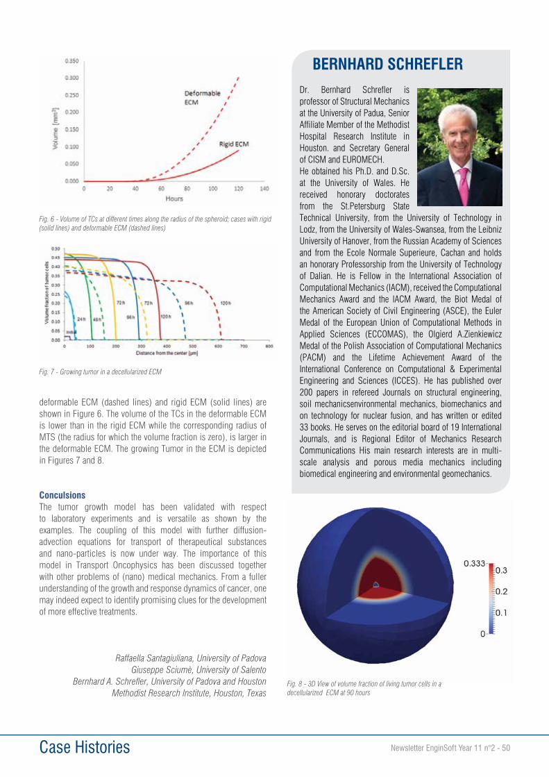
Case Histories Newsletter EnginSoft Year 11 n°2 - 50
deformable ECM (dashed lines) and rigid ECM (solid lines) are shown in Figure 6. The volume of the TCs in the deformable ECM is lower than in the rigid ECM while the corresponding radius of MTS (the radius for which the volume fraction is zero), is larger in the deformable ECM. The growing Tumor in the ECM is depicted in Figures 7 and 8.
ConculsionsThe tumor growth model has been validated with respect to laboratory experiments and is versatile as shown by the examples. The coupling of this model with further diffusion-advection equations for transport of therapeutical substances and nano-particles is now under way. The importance of this model in Transport Oncophysics has been discussed together with other problems of (nano) medical mechanics. From a fuller understanding of the growth and response dynamics of cancer, one may indeed expect to identify promising clues for the development of more effective treatments.
Raffaella Santagiuliana, University of PadovaGiuseppe Sciumè, University of Salento
Bernhard A. Schrefler, University of Padova and Houston Methodist Research Institute, Houston, Texas
Fig. 6 - Volume of TCs at different times along the radius of the spheroid; cases with rigid (solid lines) and deformable ECM (dashed lines)
Fig. 7 - Growing tumor in a decellularized ECM
Fig. 8 - 3D View of volume fraction of living tumor cells in a decellularized ECM at 90 hours
BERNHARD SCHREFLERDr. Bernhard Schrefler is professor of Structural Mechanics at the University of Padua, Senior Affiliate Member of the Methodist Hospital Research Institute in Houston. and Secretary General of CISM and EUROMECH.He obtained his Ph.D. and D.Sc. at the University of Wales. He received honorary doctorates from the St.Petersburg State Technical University, from the University of Technology in Lodz, from the University of Wales-Swansea, from the Leibniz University of Hanover, from the Russian Academy of Sciences and from the Ecole Normale Superieure, Cachan and holds an honorary Professorship from the University of Technology of Dalian. He is Fellow in the International Association of Computational Mechanics (IACM), received the Computational Mechanics Award and the IACM Award, the Biot Medal of the American Society of Civil Engineering (ASCE), the Euler Medal of the European Union of Computational Methods in Applied Sciences (ECCOMAS), the Olgierd A.Zienkiewicz Medal of the Polish Association of Computational Mechanics (PACM) and the Lifetime Achievement Award of the International Conference on Computational & Experimental Engineering and Sciences (ICCES). He has published over 200 papers in refereed Journals on structural engineering, soil mechanicsenvironmental mechanics, biomechanics and on technology for nuclear fusion, and has written or edited 33 books. He serves on the editorial board of 19 International Journals, and is Regional Editor of Mechanics Research Communications His main research interests are in multi-scale analysis and porous media mechanics including biomedical engineering and environmental geomechanics.
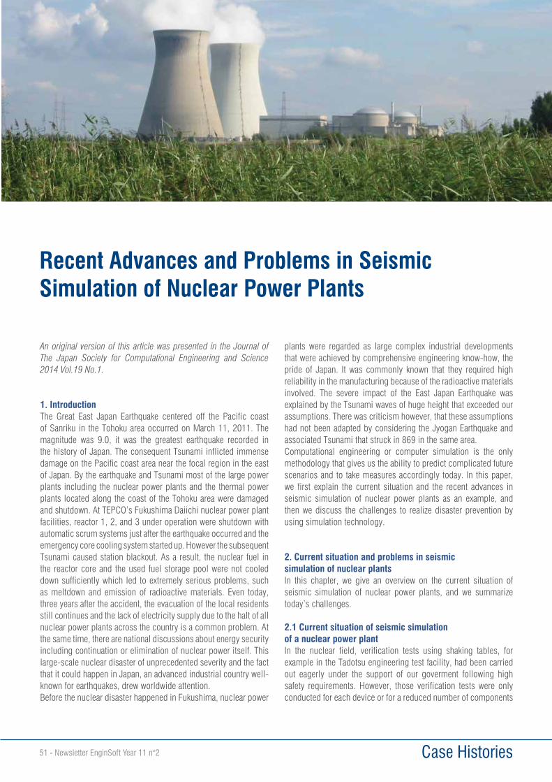
Case Histories51 - Newsletter EnginSoft Year 11 n°2
An original version of this article was presented in the Journal of The Japan Society for Computational Engineering and Science 2014 Vol.19 No.1.
1. IntroductionThe Great East Japan Earthquake centered off the Pacific coast of Sanriku in the Tohoku area occurred on March 11, 2011. The magnitude was 9.0, it was the greatest earthquake recorded in the history of Japan. The consequent Tsunami inflicted immense damage on the Pacific coast area near the focal region in the east of Japan. By the earthquake and Tsunami most of the large power plants including the nuclear power plants and the thermal power plants located along the coast of the Tohoku area were damaged and shutdown. At TEPCO’s Fukushima Daiichi nuclear power plant facilities, reactor 1, 2, and 3 under operation were shutdown with automatic scrum systems just after the earthquake occurred and the emergency core cooling system started up. However the subsequent Tsunami caused station blackout. As a result, the nuclear fuel in the reactor core and the used fuel storage pool were not cooled down sufficiently which led to extremely serious problems, such as meltdown and emission of radioactive materials. Even today, three years after the accident, the evacuation of the local residents still continues and the lack of electricity supply due to the halt of all nuclear power plants across the country is a common problem. At the same time, there are national discussions about energy security including continuation or elimination of nuclear power itself. This large-scale nuclear disaster of unprecedented severity and the fact that it could happen in Japan, an advanced industrial country well-known for earthquakes, drew worldwide attention.Before the nuclear disaster happened in Fukushima, nuclear power
plants were regarded as large complex industrial developments that were achieved by comprehensive engineering know-how, the pride of Japan. It was commonly known that they required high reliability in the manufacturing because of the radioactive materials involved. The severe impact of the East Japan Earthquake was explained by the Tsunami waves of huge height that exceeded our assumptions. There was criticism however, that these assumptions had not been adapted by considering the Jyogan Earthquake and associated Tsunami that struck in 869 in the same area.Computational engineering or computer simulation is the only methodology that gives us the ability to predict complicated future scenarios and to take measures accordingly today. In this paper, we first explain the current situation and the recent advances in seismic simulation of nuclear power plants as an example, and then we discuss the challenges to realize disaster prevention by using simulation technology.
2. Current situation and problems in seismic simulation of nuclear plantsIn this chapter, we give an overview on the current situation of seismic simulation of nuclear power plants, and we summarize today’s challenges.
2.1 Current situation of seismic simulation of a nuclear power plantIn the nuclear field, verification tests using shaking tables, for example in the Tadotsu engineering test facility, had been carried out eagerly under the support of our goverment following high safety requirements. However, those verification tests were only conducted for each device or for a reduced number of components
Recent Advances and Problems in Seismic Simulation of Nuclear Power Plants
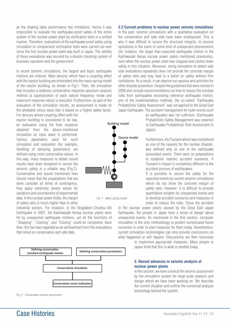
Case Histories Newsletter EnginSoft Year 11 n°2 - 52
as the shaking table performance has limitations. Hence it was impossible to evaluate the earthquake-proof safety of the entire system of the nuclear power plant by verification tests in a unified manner. Therefore, evaluations of the earthquake proof safety using simulation to complement verification tests were carried out ever since the first nuclear power plant was built in Japan. The validity of these evaluations was secured by a double checking system of business operators and the government.
In recent seismic simulations, the largest and basic earthquake motions are entered. Main devices which have a coupling effect with the reactor building are embedded into the mass-spring model of the reactor building, as shown in Fig.1. Then, the simulation that includes a relatively conservative response spectrum analysis method (a superposition of each natural frequency mode and maximum response value) is executed. Furthermore, as part of the evaluation of the simulation results, an assessment is made on the allowable stress value that is based on a higher safety factor. For devices whose coupling effect with the reactor building is considered to be low, an evaluation using the floor response obtained from the above-mentioned simulation as input wave is performed. Various parameters used for such simulation and evaluation (for example, handling of damping parameters) are defined using more conservative values. In this way, many measures to obtain sound results have been designed to secure the seismic safety in a reliable way (Fig.2). Conservative and sound mentioned here should mean that the preparations that are done consider all kinds of contingency, they apply extremely severe values for variations and uncertainties of experimental data. In the nuclear power fields, the margin of safety ratio is much higher than in other industrial sectors. For instance, in the Niigataken-Chuetsu-Oki Earthquake in 2007, the Kashiwazaki Kariya nuclear plants were hit by unexpected earthquake motions, yet all the functions of “Stopping”, “Cooling”, and “Closing” could be completed. Back then, this fact was regarded as an achievement from the evaluations that relied on conservative and safe data.
2.2 Current problems in nuclear power seismic simulationsIn the past, seismic simulations with a qualitative evaluation on the conservative and safe side have been emphasized. This is why it was difficult to secure the structural integrity, to resume operations in the event of some kind of unexpected phenomenon (for instance, the larger-than-expected earthquake motion in the Kashiwazaki Kariya nuclear power plants mentioned previously), even when the nuclear power plant was stopped and cooled down safely in this situation. Moreover, doing simulation to obtain safe side evaluations repeatedly does not provide the concrete margin of safety ratio and may lead to a belief on safety without firm confidence. As a result, it can deprive our passion and activities for other disaster prevention. Despite the guidelines that were revised in 2006 and include recommendations on how to reduce the residual risks from earthquakes exceeding reference earthquake motion, one of the implementation methods, the so-called “Earthquake Probabilistic Safety Assessment” was not applied to the Great East Japan Earthquake. The accident management for outer events such
as earthquakes was not sufficient. (Earthquake Probabilistic Safety Management was renamed to Earthquake Probabilistic Risk Assessment in Japan).
Furthermore, the Tsunami which was considered as one of the reasons for the nuclear disaster, was defined only as one of the earthquake associated events. There were no preparations to establish realistic accident scenarios. A Tsunami’s impact is completely different to the accident process of earthquakes.It is possible to secure the safety for the expected events by current seismic simulations which do not show the concrete margin of safety ratio. However, it is difficult to provide quantitative insights for unexpected events and to develop accident scenarios and measures in order to reduce the risks. Since the accident
in the nuclear power plants caused by the Great East Japan Earthquake, the people in Japan have a sense of danger about unexpected events. As mentioned in the first section, computer simulation is the only methodology to predict complicated future scenarios in order to plan measures for them today. Nevertheless, current simulation technologies can only provide conclusions on what happened or will happen. Discussions are then necessary
to implement appropriate measures. Many people in Japan think that this is what is needed today.
3. Recent advances in seismic analysis of nuclear power plantsIn this section, we have a look at the seismic assessment by the simulation system for large-scale analysis and design which we have been working on. We describe the current situation and outline the numerical analysis technology behind the system.
Fig. 1 - Mass-spring model
Fig. 2 - Conservative seismic assessment
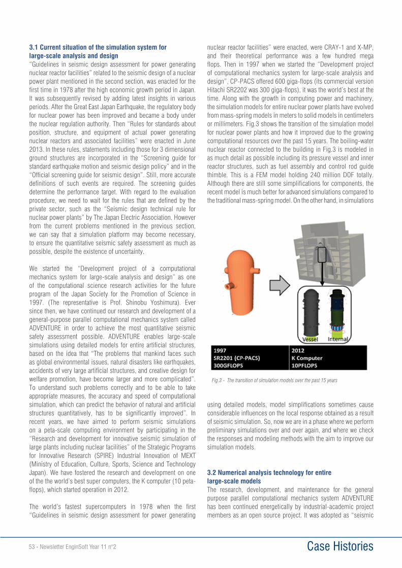
Case Histories53 - Newsletter EnginSoft Year 11 n°2
3.1 Current situation of the simulation system for large-scale analysis and design“Guidelines in seismic design assessment for power generating nuclear reactor facilities” related to the seismic design of a nuclear power plant mentioned in the second section, was enacted for the first time in 1978 after the high economic growth period in Japan. It was subsequently revised by adding latest insights in various periods. After the Great East Japan Earthquake, the regulatory body for nuclear power has been improved and became a body under the nuclear regulation authority. Then “Rules for standards about position, structure, and equipment of actual power generating nuclear reactors and associated facilities” were enacted in June 2013. In these rules, statements including those for 3 dimensional ground structures are incorporated in the “Screening guide for standard earthquake motion and seismic design policy” and in the “Official screening guide for seismic design”. Still, more accurate definitions of such events are required. The screening guides determine the performance target. With regard to the evaluation procedure, we need to wait for the rules that are defined by the private sector, such as the “Seismic design technical rule for nuclear power plants” by The Japan Electric Association. However from the current problems mentioned in the previous section, we can say that a simulation platform may become necessary, to ensure the quantitative seismic safety assessment as much as possible, despite the existence of uncertainty.
We started the “Development project of a computational mechanics system for large-scale analysis and design” as one of the computational science research activities for the future program of the Japan Society for the Promotion of Science in 1997. (The representative is Prof. Shinobu Yoshimura). Ever since then, we have continued our research and development of a general-purpose parallel computational mechanics system called ADVENTURE in order to achieve the most quantitative seismic safety assessment possible. ADVENTURE enables large-scale simulations using detailed models for entire artificial structures, based on the idea that “The problems that mankind faces such as global environmental issues, natural disasters like earthquakes, accidents of very large artificial structures, and creative design for welfare promotion, have become larger and more complicated”. To understand such problems correctly and to be able to take appropriate measures, the accuracy and speed of computational simulation, which can predict the behavior of natural and artificial structures quantitatively, has to be significantly improved”. In recent years, we have aimed to perform seismic simulations on a peta-scale computing environment by participating in the “Research and development for innovative seismic simulation of large plants including nuclear facilities” of the Strategic Programs for Innovative Research (SPIRE) Industrial Innovation of MEXT (Ministry of Education, Culture, Sports, Science and Technology Japan). We have fostered the research and development on one of the the world’s best super computers, the K computer (10 peta-flops), which started operation in 2012.
The world’s fastest supercomputers in 1978 when the first “Guidelines in seismic design assessment for power generating
nuclear reactor facilities” were enacted, were CRAY-1 and X-MP, and their theoretical performance was a few hundred mega flops. Then in 1997 when we started the “Development project of computational mechanics system for large-scale analysis and design”, CP-PACS offered 600 giga-flops (its commercial version Hitachi SR2202 was 300 giga-flops), it was the world’s best at the time. Along with the growth in computing power and machinery, the simulation models for entire nuclear power plants have evolved from mass-spring models in meters to solid models in centimeters or millimeters. Fig.3 shows the transition of the simulation model for nuclear power plants and how it improved due to the growing computational resources over the past 15 years. The boiling-water nuclear reactor connected to the building in Fig.3 is modeled in as much detail as possible including its pressure vessel and inner reactor structures, such as fuel assembly and control rod guide thimble. This is a FEM model holding 240 million DOF totally. Although there are still some simplifications for components, the recent model is much better for advanced simulations compared to the traditional mass-spring model. On the other hand, in simulations
using detailed models, model simplifications sometimes cause considerable influences on the local response obtained as a result of seismic simulation. So, now we are in a phase where we perform preliminary simulations over and over again, and where we check the responses and modeling methods with the aim to improve our simulation models.
3.2 Numerical analysis technology for entire large-scale modelsThe research, development, and maintenance for the general purpose parallel computational mechanics system ADVENTURE has been continued energetically by industrial-academic project members as an open source project. It was adopted as “seismic
Fig.3 - The transition of simulation models over the past 15 years
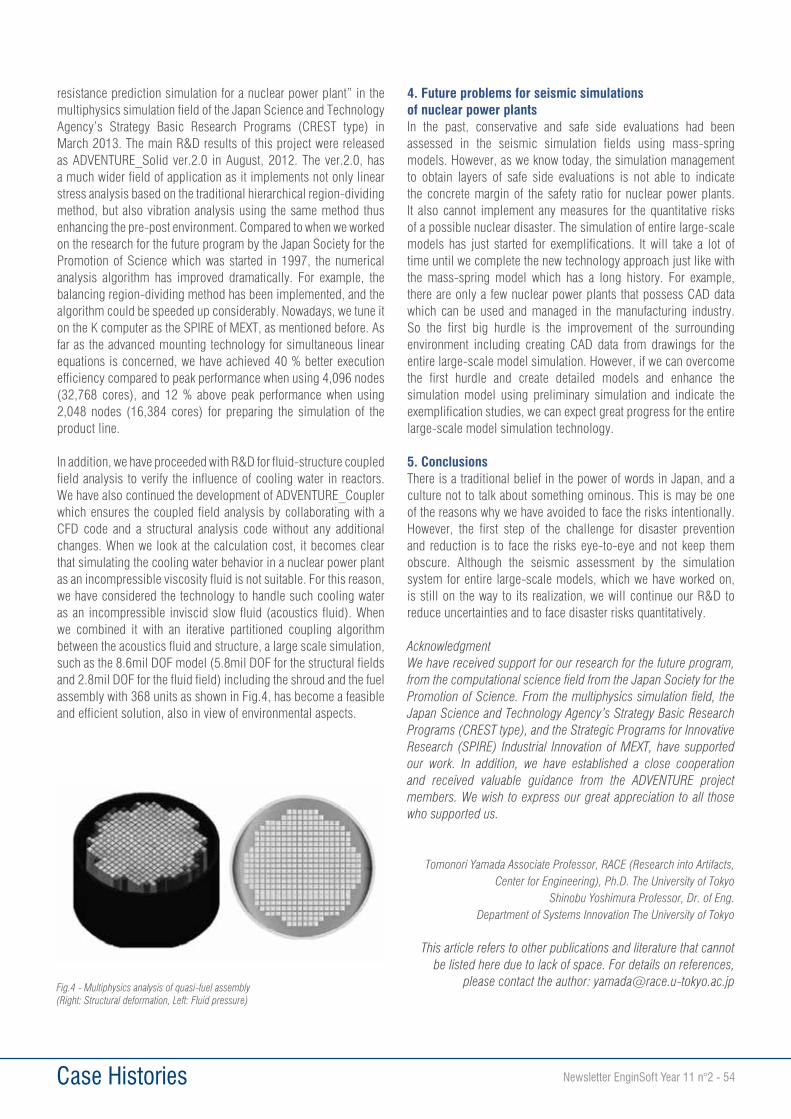
Case Histories Newsletter EnginSoft Year 11 n°2 - 54
resistance prediction simulation for a nuclear power plant” in the multiphysics simulation field of the Japan Science and Technology Agency’s Strategy Basic Research Programs (CREST type) in March 2013. The main R&D results of this project were released as ADVENTURE_Solid ver.2.0 in August, 2012. The ver.2.0, has a much wider field of application as it implements not only linear stress analysis based on the traditional hierarchical region-dividing method, but also vibration analysis using the same method thus enhancing the pre-post environment. Compared to when we worked on the research for the future program by the Japan Society for the Promotion of Science which was started in 1997, the numerical analysis algorithm has improved dramatically. For example, the balancing region-dividing method has been implemented, and the algorithm could be speeded up considerably. Nowadays, we tune it on the K computer as the SPIRE of MEXT, as mentioned before. As far as the advanced mounting technology for simultaneous linear equations is concerned, we have achieved 40 % better execution efficiency compared to peak performance when using 4,096 nodes (32,768 cores), and 12 % above peak performance when using 2,048 nodes (16,384 cores) for preparing the simulation of the product line.
In addition, we have proceeded with R&D for fluid-structure coupled field analysis to verify the influence of cooling water in reactors. We have also continued the development of ADVENTURE_Coupler which ensures the coupled field analysis by collaborating with a CFD code and a structural analysis code without any additional changes. When we look at the calculation cost, it becomes clear that simulating the cooling water behavior in a nuclear power plant as an incompressible viscosity fluid is not suitable. For this reason, we have considered the technology to handle such cooling water as an incompressible inviscid slow fluid (acoustics fluid). When we combined it with an iterative partitioned coupling algorithm between the acoustics fluid and structure, a large scale simulation, such as the 8.6mil DOF model (5.8mil DOF for the structural fields and 2.8mil DOF for the fluid field) including the shroud and the fuel assembly with 368 units as shown in Fig.4, has become a feasible and efficient solution, also in view of environmental aspects.
4. Future problems for seismic simulations of nuclear power plantsIn the past, conservative and safe side evaluations had been assessed in the seismic simulation fields using mass-spring models. However, as we know today, the simulation management to obtain layers of safe side evaluations is not able to indicate the concrete margin of the safety ratio for nuclear power plants. It also cannot implement any measures for the quantitative risks of a possible nuclear disaster. The simulation of entire large-scale models has just started for exemplifications. It will take a lot of time until we complete the new technology approach just like with the mass-spring model which has a long history. For example, there are only a few nuclear power plants that possess CAD data which can be used and managed in the manufacturing industry. So the first big hurdle is the improvement of the surrounding environment including creating CAD data from drawings for the entire large-scale model simulation. However, if we can overcome the first hurdle and create detailed models and enhance the simulation model using preliminary simulation and indicate the exemplification studies, we can expect great progress for the entire large-scale model simulation technology.
5. ConclusionsThere is a traditional belief in the power of words in Japan, and a culture not to talk about something ominous. This is may be one of the reasons why we have avoided to face the risks intentionally. However, the first step of the challenge for disaster prevention and reduction is to face the risks eye-to-eye and not keep them obscure. Although the seismic assessment by the simulation system for entire large-scale models, which we have worked on, is still on the way to its realization, we will continue our R&D to reduce uncertainties and to face disaster risks quantitatively.
AcknowledgmentWe have received support for our research for the future program, from the computational science field from the Japan Society for the Promotion of Science. From the multiphysics simulation field, the Japan Science and Technology Agency’s Strategy Basic Research Programs (CREST type), and the Strategic Programs for Innovative Research (SPIRE) Industrial Innovation of MEXT, have supported our work. In addition, we have established a close cooperation and received valuable guidance from the ADVENTURE project members. We wish to express our great appreciation to all those who supported us.
Tomonori Yamada Associate Professor, RACE (Research into Artifacts, Center for Engineering), Ph.D. The University of Tokyo
Shinobu Yoshimura Professor, Dr. of Eng. Department of Systems Innovation The University of Tokyo
This article refers to other publications and literature that cannot be listed here due to lack of space. For details on references,
please contact the author: [email protected] - Multiphysics analysis of quasi-fuel assembly(Right: Structural deformation, Left: Fluid pressure)
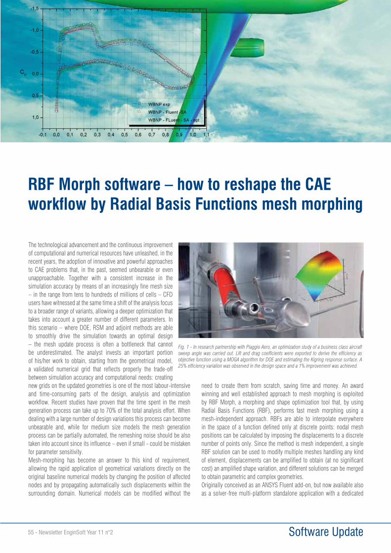
Software Update55 - Newsletter EnginSoft Year 11 n°2
The technological advancement and the continuous improvement of computational and numerical resources have unleashed, in the recent years, the adoption of innovative and powerful approaches to CAE problems that, in the past, seemed unbearable or even unapproachable. Together with a consistent increase in the simulation accuracy by means of an increasingly fine mesh size – in the range from tens to hundreds of millions of cells – CFD users have witnessed at the same time a shift of the analysis focus to a broader range of variants, allowing a deeper optimization that takes into account a greater number of different parameters. In this scenario – where DOE, RSM and adjoint methods are able to smoothly drive the simulation towards an optimal design – the mesh update process is often a bottleneck that cannot be underestimated. The analyst invests an important portion of his/her work to obtain, starting from the geometrical model, a validated numerical grid that reflects properly the trade-off between simulation accuracy and computational needs: creating new grids on the updated geometries is one of the most labour-intensive and time-consuming parts of the design, analysis and optimization workflow. Recent studies have proven that the time spent in the mesh generation process can take up to 70% of the total analysis effort. When dealing with a large number of design variations this process can become unbearable and, while for medium size models the mesh generation process can be partially automated, the remeshing noise should be also taken into account since its influence – even if small - could be mistaken for parameter sensitivity.Mesh-morphing has become an answer to this kind of requirement, allowing the rapid application of geometrical variations directly on the original baseline numerical models by changing the position of affected nodes and by propagating automatically such displacements within the surrounding domain. Numerical models can be modified without the
need to create them from scratch, saving time and money. An award winning and well established approach to mesh morphing is exploited by RBF Morph, a morphing and shape optimization tool that, by using Radial Basis Functions (RBF), performs fast mesh morphing using a mesh-independent approach. RBFs are able to interpolate everywhere in the space of a function defined only at discrete points: nodal mesh positions can be calculated by imposing the displacements to a discrete number of points only. Since the method is mesh independent, a single RBF solution can be used to modify multiple meshes handling any kind of element, displacements can be amplified to obtain (at no significant cost) an amplified shape variation, and different solutions can be merged to obtain parametric and complex geometries.Originally conceived as an ANSYS Fluent add-on, but now available also as a solver-free multi-platform standalone application with a dedicated
RBF Morph software – how to reshape the CAE workflow by Radial Basis Functions mesh morphing
Fig. 1 - In research partnership with Piaggio Aero, an optimization study of a business class aircraft sweep angle was carried out. Lift and drag coefficients were exported to derive the efficiency as objective function using a MOGA algorithm for DOE and estimating the Kigring response surface. A 25% efficiency variation was observed in the design space and a 1% improvement was achieved.
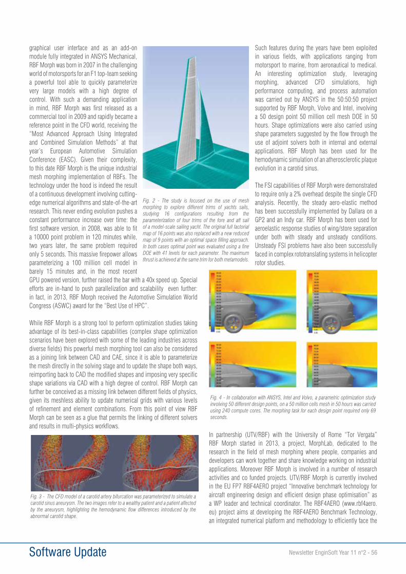
Software Update Newsletter EnginSoft Year 11 n°2 - 56
graphical user interface and as an add-on module fully integrated in ANSYS Mechanical, RBF Morph was born in 2007 in the challenging world of motorsports for an F1 top-team seeking a powerful tool able to quickly parameterize very large models with a high degree of control. With such a demanding application in mind, RBF Morph was first released as a commercial tool in 2009 and rapidly became a reference point in the CFD world, receiving the “Most Advanced Approach Using Integrated and Combined Simulation Methods” at that year’s European Automotive Simulation Conference (EASC). Given their complexity, to this date RBF Morph is the unique industrial mesh morphing implementation of RBFs. The technology under the hood is indeed the result of a continuous development involving cutting-edge numerical algorithms and state-of-the-art research. This never ending evolution pushes a constant performance increase over time: the first software version, in 2008, was able to fit a 10000 point problem in 120 minutes while, two years later, the same problem required only 5 seconds. This massive firepower allows parameterizing a 100 million cell model in barely 15 minutes and, in the most recent GPU powered version, further raised the bar with a 40x speed up. Special efforts are in-hand to push parallelization and scalability even further: in fact, in 2013, RBF Morph received the Automotive Simulation World Congress (ASWC) award for the “Best Use of HPC”.
While RBF Morph is a strong tool to perform optimization studies taking advantage of its best-in-class capabilities (complex shape optimization scenarios have been explored with some of the leading industries across diverse fields) this powerful mesh morphing tool can also be considered as a joining link between CAD and CAE, since it is able to parameterize the mesh directly in the solving stage and to update the shape both ways, reimporting back to CAD the modified shapes and imposing very specific shape variations via CAD with a high degree of control. RBF Morph can further be conceived as a missing link between different fields of physics, given its meshless ability to update numerical grids with various levels of refinement and element combinations. From this point of view RBF Morph can be seen as a glue that permits the linking of different solvers and results in multi-physics workflows.
Such features during the years have been exploited in various fields, with applications ranging from motorsport to marine, from aeronautical to medical. An interesting optimization study, leveraging morphing, advanced CFD simulations, high performance computing, and process automation was carried out by ANSYS in the 50:50:50 project supported by RBF Morph, Volvo and Intel, involving a 50 design point 50 million cell mesh DOE in 50 hours. Shape optimizations were also carried using shape parameters suggested by the flow through the use of adjoint solvers both in internal and external applications. RBF Morph has been used for the hemodynamic simulation of an atherosclerotic plaque evolution in a carotid sinus.
The FSI capabilities of RBF Morph were demonstrated to require only a 2% overhead despite the single CFD analysis. Recently, the steady aero-elastic method has been successfully implemented by Dallara on a GP2 and an Indy car. RBF Morph has been used for aeroelastic response studies of wing/store separation under both with steady and unsteady conditions. Unsteady FSI problems have also been successfully faced in complex rototranslating systems in helicopter rotor studies.
In partnership (UTV/RBF) with the University of Rome “Tor Vergata” RBF Morph started in 2013, a project, MorphLab, dedicated to the research in the field of mesh morphing where people, companies and developers can work together and share knowledge working on industrial applications. Moreover RBF Morph is involved in a number of research activities and co funded projects. UTV/RBF Morph is currently involved in the EU FP7 RBF4AERO project “Innovative benchmark technology for aircraft engineering design and efficient design phase optimisation” as a WP leader and technical coordinator. The RBF4AERO (www.rbf4aero.eu) project aims at developing the RBF4AERO Benchmark Technology, an integrated numerical platform and methodology to efficiently face the
Fig. 2 - The study is focused on the use of mesh morphing to explore different trims of yachts sails, studying 16 configurations resulting from the parameterization of four trims of the fore and aft sail of a model-scale sailing yacht. The original full factorial map of 16 points was also replaced with a new reduced map of 9 points with an optimal space filling approach. In both cases optimal point was evaluated using a fine DOE with 41 levels for each parameter. The maximum thrust is achieved at the same trim for both metamodels.
Fig. 3 - The CFD model of a carotid artery bifurcation was parameterized to simulate a carotid sinus aneurysm. The two images refer to a wealthy patient and a patient affected by the aneurysm, highlighting the hemodynamic flow differences introduced by the abnormal carotid shape.
Fig. 4 - In collaboration with ANSYS, Intel and Volvo, a parametric optimization study involving 50 different design points, on a 50 million cells mesh in 50 hours was carried using 240 compute cores. The morphing task for each design point required only 69 seconds.
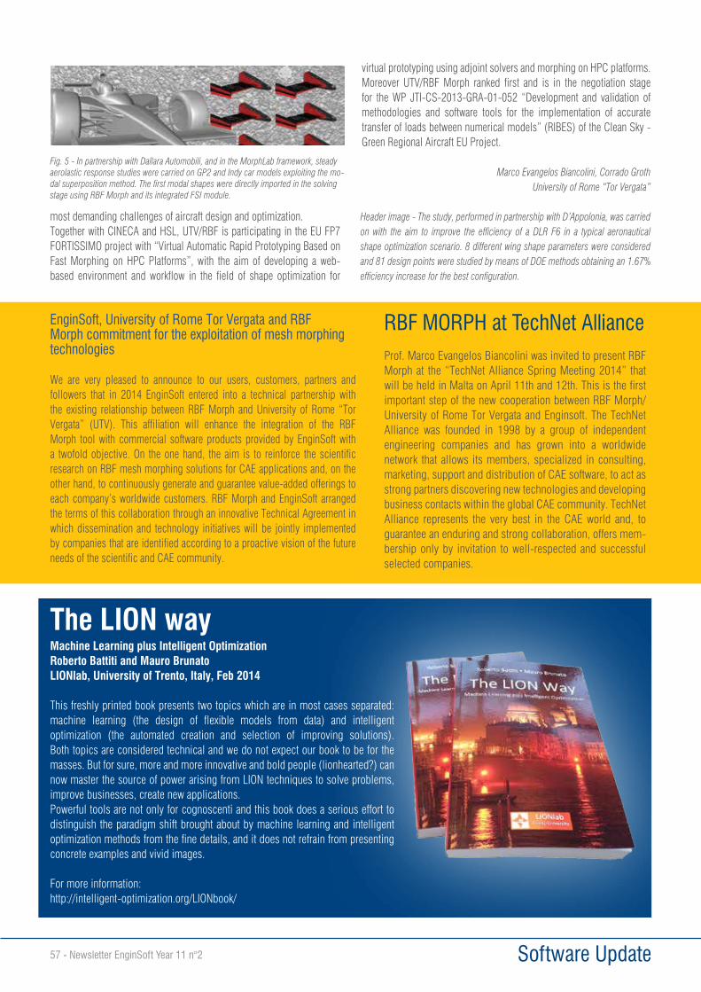
Software Update57 - Newsletter EnginSoft Year 11 n°2
most demanding challenges of aircraft design and optimization. Together with CINECA and HSL, UTV/RBF is participating in the EU FP7 FORTISSIMO project with “Virtual Automatic Rapid Prototyping Based on Fast Morphing on HPC Platforms”, with the aim of developing a web-based environment and workflow in the field of shape optimization for
virtual prototyping using adjoint solvers and morphing on HPC platforms. Moreover UTV/RBF Morph ranked first and is in the negotiation stage for the WP JTI-CS-2013-GRA-01-052 “Development and validation of methodologies and software tools for the implementation of accurate transfer of loads between numerical models” (RIBES) of the Clean Sky - Green Regional Aircraft EU Project.
Marco Evangelos Biancolini, Corrado Groth University of Rome “Tor Vergata”
Header image - The study, performed in partnership with D’Appolonia, was carried on with the aim to improve the efficiency of a DLR F6 in a typical aeronautical shape optimization scenario. 8 different wing shape parameters were considered and 81 design points were studied by means of DOE methods obtaining an 1.67% efficiency increase for the best configuration.
Fig. 5 - In partnership with Dallara Automobili, and in the MorphLab framework, steady aerolastic response studies were carried on GP2 and Indy car models exploiting the mo-dal superposition method. The first modal shapes were directly imported in the solving stage using RBF Morph and its integrated FSI module.
RBF MORPH at TechNet AllianceProf. Marco Evangelos Biancolini was invited to present RBF Morph at the “TechNet Alliance Spring Meeting 2014” that will be held in Malta on April 11th and 12th. This is the first important step of the new cooperation between RBF Morph/University of Rome Tor Vergata and Enginsoft. The TechNet Alliance was founded in 1998 by a group of independent engineering companies and has grown into a worldwide network that allows its members, specialized in consulting, marketing, support and distribution of CAE software, to act as strong partners discovering new technologies and developing business contacts within the global CAE community. TechNet Alliance represents the very best in the CAE world and, to guarantee an enduring and strong collaboration, offers mem-bership only by invitation to well-respected and successful selected companies.
The LION wayMachine Learning plus Intelligent OptimizationRoberto Battiti and Mauro BrunatoLIONlab, University of Trento, Italy, Feb 2014
This freshly printed book presents two topics which are in most cases separated: machine learning (the design of flexible models from data) and intelligent optimization (the automated creation and selection of improving solutions). Both topics are considered technical and we do not expect our book to be for the masses. But for sure, more and more innovative and bold people (lionhearted?) can now master the source of power arising from LION techniques to solve problems, improve businesses, create new applications.Powerful tools are not only for cognoscenti and this book does a serious effort to distinguish the paradigm shift brought about by machine learning and intelligent optimization methods from the fine details, and it does not refrain from presenting concrete examples and vivid images.
For more information:http://intelligent-optimization.org/LIONbook/
EnginSoft, University of Rome Tor Vergata and RBF Morph commitment for the exploitation of mesh morphing technologies
We are very pleased to announce to our users, customers, partners and followers that in 2014 EnginSoft entered into a technical partnership with the existing relationship between RBF Morph and University of Rome “Tor Vergata” (UTV). This affiliation will enhance the integration of the RBF Morph tool with commercial software products provided by EnginSoft with a twofold objective. On the one hand, the aim is to reinforce the scientific research on RBF mesh morphing solutions for CAE applications and, on the other hand, to continuously generate and guarantee value-added offerings to each company’s worldwide customers. RBF Morph and EnginSoft arranged the terms of this collaboration through an innovative Technical Agreement in which dissemination and technology initiatives will be jointly implemented by companies that are identified according to a proactive vision of the future needs of the scientific and CAE community.
Software Update Newsletter EnginSoft Year 11 n°2 - 58
The use of composite materials, especially in the automotive industry, was initially limited to few, strictly-selected applications, mainly for custom and competition vehicles. Recently these materials have begun to be employed for consumer goods, thanks to alternative manufacturing technologies which can guarantee higher production volumes. The conversion of structural components from metal materials to composite ones is an important issue that requests, for every specific case, the perfect compromise between increased performance, recycling, cost and time-to-market. A different evaluation must be considered for electric and sports cars: in their case the use of composite materials is essential for weight reduction and “composite look”. During the design development of a composite component integrated in a complex system such as a car, the analyst and the technologist play a strategic role working together in order to manage a vast number of data and parameters to fulfil the project’s requirements. The proposed solutions must be evaluated not only on the base of performance efficiency and reliability, but also according to technological restrictions due to geometry complexity, dimensional tolerances, and finishing. Numerical simulation permits the satisfaction of design challenges through a process/product approach that is completely integrated and flexible; the management of project parameters within advanced analysis tools allows the whole system’s structural behaviour to be predicted, the critical regions to be identified and the design before the component’s production to be optimized.
Composite setup in ACPThe ACP (ANSYS Composite Prep/Post) solution represents an important innovation in dealing with the design of composite structures. Its dedicated features for the modeling of complex systems allow the user to carry out the composite layup definition in a logical and efficient manner, along with joint interfaces, the integration of sandwich structures, local
reinforcements and tapering; these guided operations simplify things for the user, since he or she is able to model numerically the corresponding physical sequence which the technologist will later recognise. In this context ACP also works to support the procedure of process/product integrated design considering the technological effects of double-curvature geometries (e.g. Hand Layup, Filament Winding); in these cases it is possible to predict and check the presence of folds, thickenings and local overlappings, verifying the performance consequences of manufacturing effects.
Composite materials in LS-DYNALS-DYNA offers different pre-existing composite material models, continuously developed and implemented, to perform explicit dynamic and implicit simulations. This is the reason why LS-DYNA has traditionally been considered the benchmark for composite crash simulations.The typical materials used are:• *MAT_COMPOSITE_DAMAGE - Material Type 22. This is an
orthotropic material that allows you to insert three failure criteria. The constitutive constants can vary through the shell thickness by using the user defined integration rule.
• *MAT_ENHANCED_COMPOSITE_DAMAGE - Material Type 54-55. These are enhanced versions of the composite model material type 22. Arbitrary orthotropic materials, e.g. unidirectional layers in composite shell structures, can be defined. In addition special measures are taken for failure under compression.
• *MAT_LAMINATED_COMPOSITE_FABRIC - Material Type 58. Depending on the type of failure surface, this model may be used to model composite materials with unidirectional layers, complete laminates and woven fabrics.
• *MAT_ LAYERED_LINEAR_PLASTICITY - Material Type 114. This layered elastoplastic material permits the insertion of an arbitrary
FEM analysis of composite material using ACP and LS-DYNA
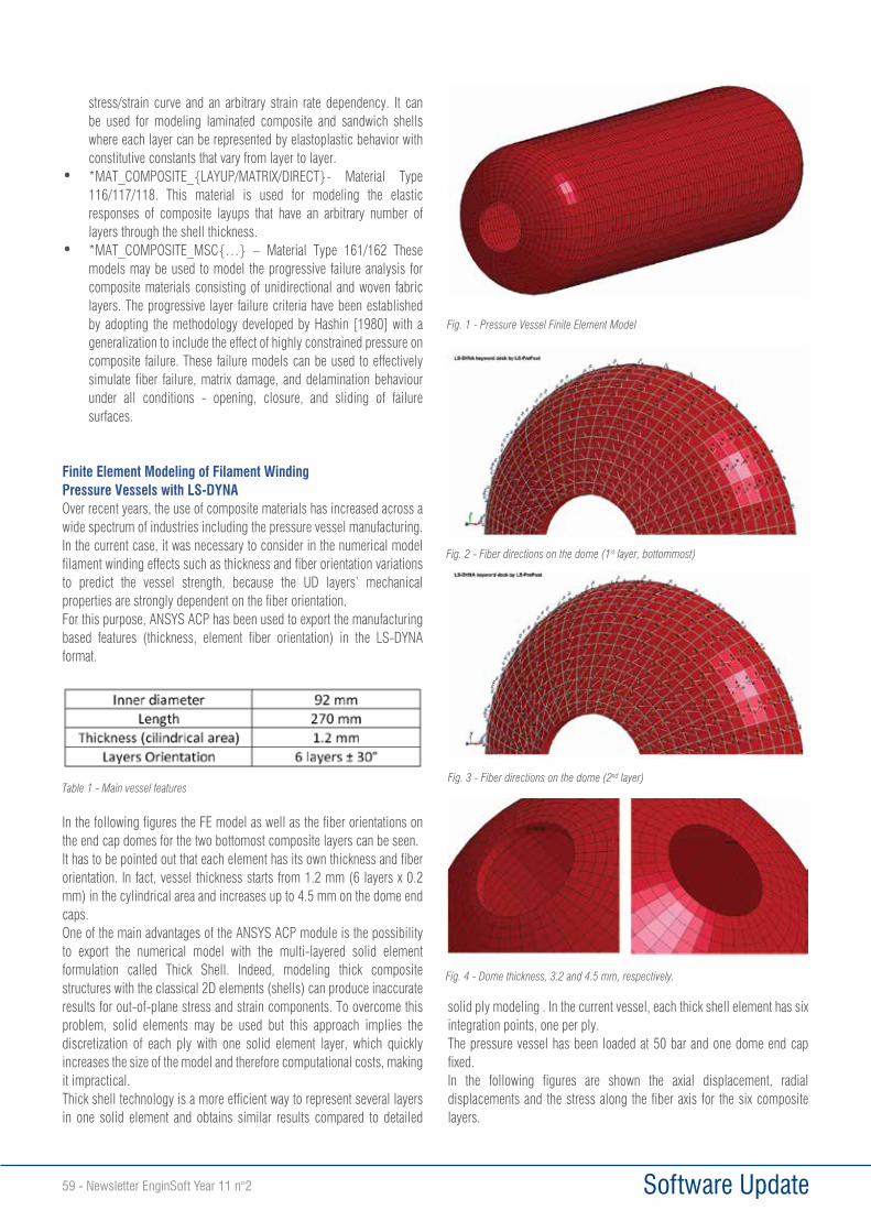
Software Update59 - Newsletter EnginSoft Year 11 n°2
stress/strain curve and an arbitrary strain rate dependency. It can be used for modeling laminated composite and sandwich shells where each layer can be represented by elastoplastic behavior with constitutive constants that vary from layer to layer.
• *MAT_COMPOSITE_{LAYUP/MATRIX/DIRECT}- Material Type 116/117/118. This material is used for modeling the elastic responses of composite layups that have an arbitrary number of layers through the shell thickness.
• *MAT_COMPOSITE_MSC{…} – Material Type 161/162 These models may be used to model the progressive failure analysis for composite materials consisting of unidirectional and woven fabric layers. The progressive layer failure criteria have been established by adopting the methodology developed by Hashin [1980] with a generalization to include the effect of highly constrained pressure on composite failure. These failure models can be used to effectively simulate fiber failure, matrix damage, and delamination behaviour under all conditions - opening, closure, and sliding of failure surfaces.
Finite Element Modeling of Filament Winding Pressure Vessels with LS-DYNAOver recent years, the use of composite materials has increased across a wide spectrum of industries including the pressure vessel manufacturing.In the current case, it was necessary to consider in the numerical model filament winding effects such as thickness and fiber orientation variations to predict the vessel strength, because the UD layers’ mechanical properties are strongly dependent on the fiber orientation.For this purpose, ANSYS ACP has been used to export the manufacturing based features (thickness, element fiber orientation) in the LS-DYNA format.
In the following figures the FE model as well as the fiber orientations on the end cap domes for the two bottomost composite layers can be seen.It has to be pointed out that each element has its own thickness and fiber orientation. In fact, vessel thickness starts from 1.2 mm (6 layers x 0.2 mm) in the cylindrical area and increases up to 4.5 mm on the dome end caps.One of the main advantages of the ANSYS ACP module is the possibility to export the numerical model with the multi-layered solid element formulation called Thick Shell. Indeed, modeling thick composite structures with the classical 2D elements (shells) can produce inaccurate results for out-of-plane stress and strain components. To overcome this problem, solid elements may be used but this approach implies the discretization of each ply with one solid element layer, which quickly increases the size of the model and therefore computational costs, making it impractical.Thick shell technology is a more efficient way to represent several layers in one solid element and obtains similar results compared to detailed
solid ply modeling . In the current vessel, each thick shell element has six integration points, one per ply.The pressure vessel has been loaded at 50 bar and one dome end cap fixed.In the following figures are shown the axial displacement, radial displacements and the stress along the fiber axis for the six composite layers.
Table 1 - Main vessel features
Fig. 1 - Pressure Vessel Finite Element Model
Fig. 2 - Fiber directions on the dome (1st layer, bottommost)
Fig. 3 - Fiber directions on the dome (2nd layer)
Fig. 4 - Dome thickness, 3.2 and 4.5 mm, respectively.
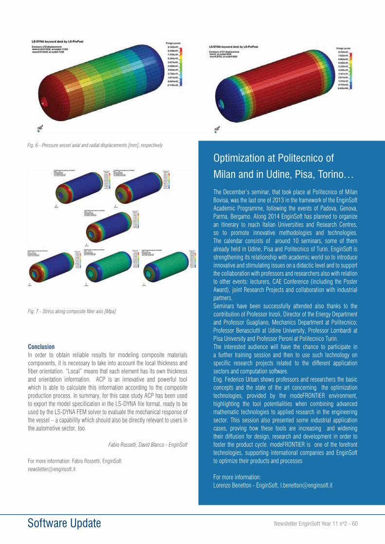
Software Update Newsletter EnginSoft Year 11 n°2 - 60
ConclusionIn order to obtain reliable results for modeling composite materials components, it is necessary to take into account the local thickness and fiber orientation. “Local” means that each element has its own thickness and orientation information. ACP is an innovative and powerful tool which is able to calculate this information according to the composite production process. In summary, for this case study ACP has been used to export the model specification in the LS-DYNA file format, ready to be used by the LS-DYNA FEM solver to evaluate the mechanical response of the vessel – a capability which should also be directly relevant to users in the automotive sector, too.
Fabio Rossetti, David Blanco - EnginSoft
For more information: Fabio Rossetti, [email protected]
Fig. 6 - Pressure vessel axial and radial displacements [mm], respectively
Fig. 7 - Stress along composite fiber axis [Mpa]
Optimization at Politecnico of
Milan and in Udine, Pisa, Torino…
The December’s seminar, that took place at Politecnico of Milan Bovisa, was the last one of 2013 in the framework of the EnginSoft Academic Programme, following the events of Padova, Genova, Parma, Bergamo. Along 2014 EnginSoft has planned to organize an itinerary to reach Italian Universities and Research Centres, so to promote innovative methodologies and technologies. The calendar consists of around 10 seminars, some of them already held in Udine, Pisa and Politecnico of Turin. EnginSoft is strengthening its relationship with academic world so to introduce innovative and stimulating issues on a didactic level and to support the collaboration with professors and researchers also with relation to other events: lecturers, CAE Conference (including the Poster Award), joint Research Projects and collaboration with industrial partners.Seminars have been successfully attended also thanks to the contribution of Professor Inzoli, Director of the Energy Department and Professor Guagliano, Mechanics Department at Politecnico; Professor Benasciutti at Udine University, Professor Lombardi at Pisa University and Professor Peroni at Politecnico Turin. The interested audience will have the chance to participate in a further training session and then to use such technology on specific research projects related to the different application sectors and computation software.Eng. Federico Urban shows professors and researchers the basic concepts and the state of the art concerning the optimization technologies, provided by the modeFRONTIER environment, highlighting the tool potentialities when combining advanced mathematic technologies to applied research in the engineering sector. This session also presented some industrial application cases, proving how these tools are increasing and widening their diffusion for design, research and development in order to foster the product cycle. modeFRONTIER is one of the forefront technologies, supporting international companies and EnginSoft to optimize their products and processes
For more information:Lorenzo Benetton - EnginSoft, [email protected]
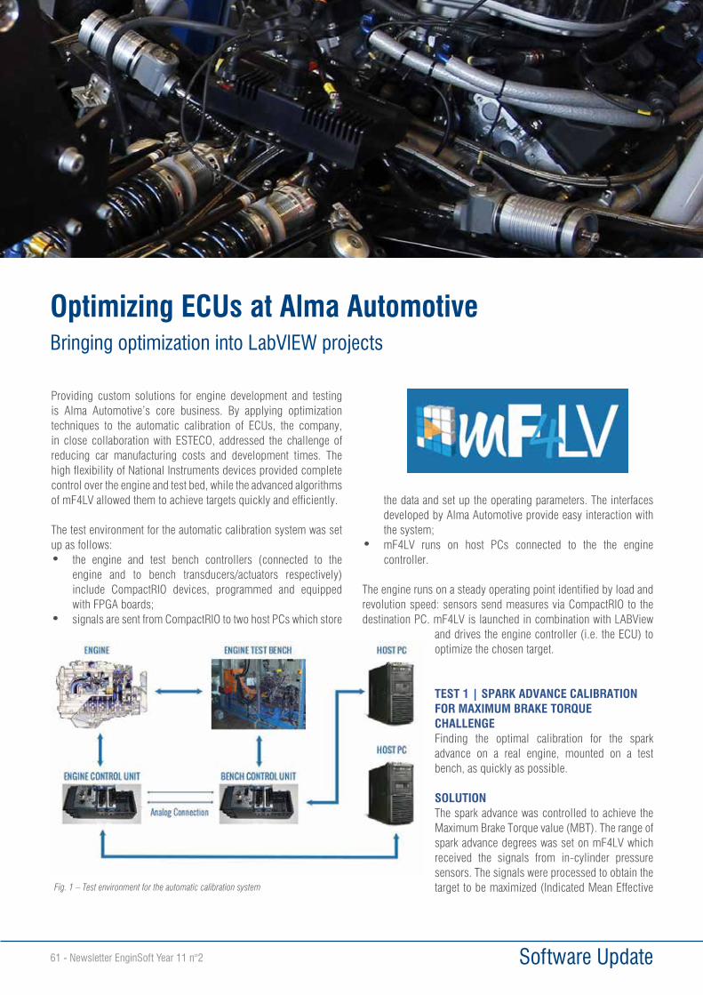
Software Update61 - Newsletter EnginSoft Year 11 n°2
Providing custom solutions for engine development and testing is Alma Automotive’s core business. By applying optimization techniques to the automatic calibration of ECUs, the company, in close collaboration with ESTECO, addressed the challenge of reducing car manufacturing costs and development times. The high flexibility of National Instruments devices provided complete control over the engine and test bed, while the advanced algorithms of mF4LV allowed them to achieve targets quickly and efficiently.
The test environment for the automatic calibration system was set up as follows:• the engine and test bench controllers (connected to the
engine and to bench transducers/actuators respectively) include CompactRIO devices, programmed and equipped with FPGA boards;
• signals are sent from CompactRIO to two host PCs which store
the data and set up the operating parameters. The interfaces developed by Alma Automotive provide easy interaction with the system;
• mF4LV runs on host PCs connected to the the engine controller.
The engine runs on a steady operating point identified by load and revolution speed: sensors send measures via CompactRIO to the destination PC. mF4LV is launched in combination with LABView
and drives the engine controller (i.e. the ECU) to optimize the chosen target.
TEST 1 | SPARK ADVANCE CALIBRATION FOR MAXIMUM BRAKE TORQUE CHALLENGEFinding the optimal calibration for the spark advance on a real engine, mounted on a test bench, as quickly as possible.
SOLUTIONThe spark advance was controlled to achieve the Maximum Brake Torque value (MBT). The range of spark advance degrees was set on mF4LV which received the signals from in-cylinder pressure sensors. The signals were processed to obtain the target to be maximized (Indicated Mean Effective
Optimizing ECUs at Alma AutomotiveBringing optimization into LabVIEW projects
Fig. 1 – Test environment for the automatic calibration system
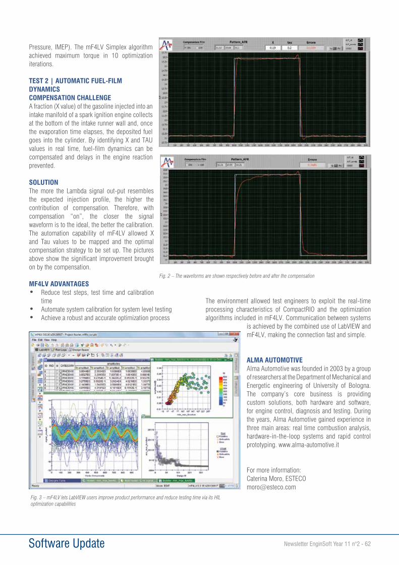
Software Update Newsletter EnginSoft Year 11 n°2 - 62
Pressure, IMEP). The mF4LV Simplex algorithm achieved maximum torque in 10 optimization iterations.
TEST 2 | AUTOMATIC FUEL-FILM DYNAMICS COMPENSATION CHALLENGEA fraction (X value) of the gasoline injected into an intake manifold of a spark ignition engine collects at the bottom of the intake runner wall and, once the evaporation time elapses, the deposited fuel goes into the cylinder. By identifying X and TAU values in real time, fuel-film dynamics can be compensated and delays in the engine reaction prevented.
SOLUTIONThe more the Lambda signal out-put resembles the expected injection profile, the higher the contribution of compensation. Therefore, with compensation “on”, the closer the signal waveform is to the ideal, the better the calibration. The automation capability of mF4LV allowed X and Tau values to be mapped and the optimal compensation strategy to be set up. The pictures above show the significant improvement brought on by the compensation.
MF4LV ADVANTAGES• Reduce test steps, test time and calibration
time • Automate system calibration for system level testing• Achieve a robust and accurate optimization process
The environment allowed test engineers to exploit the real-time processing characteristics of CompactRIO and the optimization algorithms included in mF4LV. Communication between systems
is achieved by the combined use of LabVIEW and mF4LV, making the connection fast and simple.
ALMA AUTOMOTIVEAlma Automotive was founded in 2003 by a group of researchers at the Department of Mechanical and Energetic engineering of University of Bologna. The company’s core business is providing custom solutions, both hardware and software, for engine control, diagnosis and testing. During the years, Alma Automotive gained experience in three main areas: real time combustion analysis, hardware-in-the-loop systems and rapid control prototyping. www.alma-automotive.it
For more information:Caterina Moro, [email protected]
Fig. 2 – The waveforms are shown respectively before and after the compensation
Fig. 3 – mF4LV lets LabVIEW users improve product performance and reduce testing time via its HIL optimization capabilities
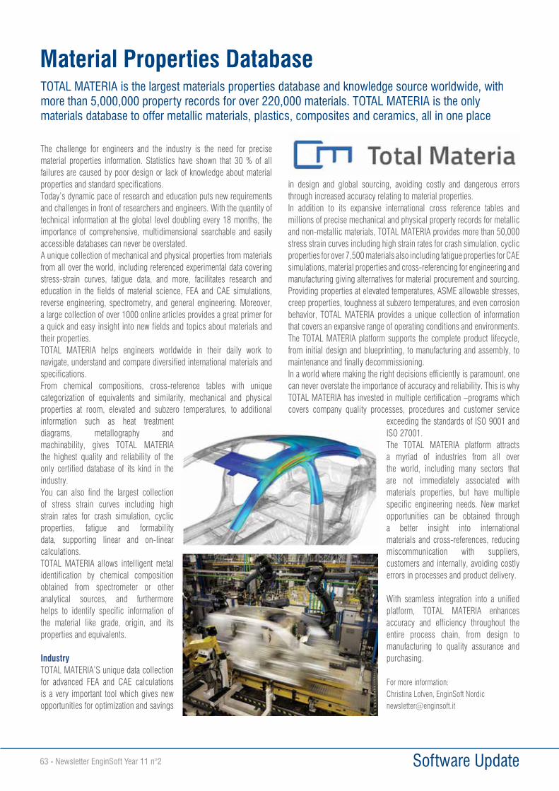
Software Update63 - Newsletter EnginSoft Year 11 n°2
The challenge for engineers and the industry is the need for precise material properties information. Statistics have shown that 30 % of all failures are caused by poor design or lack of knowledge about material properties and standard specifications.Today’s dynamic pace of research and education puts new requirements and challenges in front of researchers and engineers. With the quantity of technical information at the global level doubling every 18 months, the importance of comprehensive, multidimensional searchable and easily accessible databases can never be overstated. A unique collection of mechanical and physical properties from materials from all over the world, including referenced experimental data covering stress-strain curves, fatigue data, and more, facilitates research and education in the fields of material science, FEA and CAE simulations, reverse engineering, spectrometry, and general engineering. Moreover, a large collection of over 1000 online articles provides a great primer for a quick and easy insight into new fields and topics about materials and their properties.TOTAL MATERIA helps engineers worldwide in their daily work to navigate, understand and compare diversified international materials and specifications.From chemical compositions, cross-reference tables with unique categorization of equivalents and similarity, mechanical and physical properties at room, elevated and subzero temperatures, to additional information such as heat treatment diagrams, metallography and machinability, gives TOTAL MATERIA the highest quality and reliability of the only certified database of its kind in the industry.You can also find the largest collection of stress strain curves including high strain rates for crash simulation, cyclic properties, fatigue and formability data, supporting linear and on-linear calculations. TOTAL MATERIA allows intelligent metal identification by chemical composition obtained from spectrometer or other analytical sources, and furthermore helps to identify specific information of the material like grade, origin, and its properties and equivalents.
IndustryTOTAL MATERIA’S unique data collection for advanced FEA and CAE calculations is a very important tool which gives new opportunities for optimization and savings
in design and global sourcing, avoiding costly and dangerous errors through increased accuracy relating to material properties.In addition to its expansive international cross reference tables and millions of precise mechanical and physical property records for metallic and non-metallic materials, TOTAL MATERIA provides more than 50,000 stress strain curves including high strain rates for crash simulation, cyclic properties for over 7,500 materials also including fatigue properties for CAE simulations, material properties and cross-referencing for engineering and manufacturing giving alternatives for material procurement and sourcing. Providing properties at elevated temperatures, ASME allowable stresses, creep properties, toughness at subzero temperatures, and even corrosion behavior, TOTAL MATERIA provides a unique collection of information that covers an expansive range of operating conditions and environments. The TOTAL MATERIA platform supports the complete product lifecycle, from initial design and blueprinting, to manufacturing and assembly, to maintenance and finally decommissioning. In a world where making the right decisions efficiently is paramount, one can never overstate the importance of accuracy and reliability. This is why TOTAL MATERIA has invested in multiple certification –programs which covers company quality processes, procedures and customer service
exceeding the standards of ISO 9001 and ISO 27001.The TOTAL MATERIA platform attracts a myriad of industries from all over the world, including many sectors that are not immediately associated with materials properties, but have multiple specific engineering needs. New market opportunities can be obtained through a better insight into international materials and cross-references, reducing miscommunication with suppliers, customers and internally, avoiding costly errors in processes and product delivery.
With seamless integration into a unified platform, TOTAL MATERIA enhances accuracy and efficiency throughout the entire process chain, from design to manufacturing to quality assurance and purchasing.
For more information:Christina Lofven, EnginSoft [email protected]
Material Properties Database TOTAL MATERIA is the largest materials properties database and knowledge source worldwide, with more than 5,000,000 property records for over 220,000 materials. TOTAL MATERIA is the only materials database to offer metallic materials, plastics, composites and ceramics, all in one place

Research & Technology Transfer Newsletter EnginSoft Year 11 n°2 - 64
CSP technologyThe exploitation of solar thermal energy is increasingly spreading worldwide and can provide heat at low, medium and high temperatures. Therefore, this renewable energy source can be used for several purposes, ranging from household to industrial applications.
Concentrated solar power (CSP) plants use mirrors to concentrate the sun rays on a smaller surface target, the receiver, and provide high-temperature heat to a process or heat transfer fluid. In currently-operating CSP installations, the heat collected is mainly used to produce electricity from a renewable, carbon-free source through a thermodynamic cycle. For this application, solar troughs are now the most mature and verified technology, with several hundred MWel in operation especially in the south-western United States and Spain.
The heat collected in a CSP plant can also be used to power a chemical process. In this field, an application on which many research institutions and private companies have been working for several years is the production of hydrogen from the splitting of water, in order to produce a clean, efficient and carbon-free fuel.
The main issue related to the use of solar thermal energy is the intrinsic discontinuity of the solar radiation. Indeed, most of the processes that could be powered by solar energy must be operated continuously and cannot afford daily start-up and shut-down operations both for economic and technical reasons. This is particularly true when solar heat must be used in a chemical plant.
Heat storage systemsIn order to solve the continuity issue, CSP plants may be coupled with a heat storage system that accumulates heat in a high heat capacity medium to deliver energy even when the sky is cloudy or after sunset. Such thermal storage significantly improves the “capacity factor” of the plant, as well as the integration with the power grid and economic competitiveness, but requires the solar field
to be oversized compared to its nominal power output. A trade-off must be evaluated between the increase in cost associated with the thermal storage system and the economic benefit resulting from the increased energy production. Molten nitrate mixtures provide a viable large scale thermal storage medium, reaching storage efficiencies higher than 99% and the possibility to provide 24 h solar heat at constant rate due to their high heat capacity per unit volume. Compared with organic oils, molten nitrate mixtures are stable at high temperatures (up to 600°C), relatively inexpensive and widely available, not flammable, and have minor environmental impact; moreover, these molten salts have very low vapour pressure (i.e., do not require pressurized systems) and low corrosion rates with common-piping materials. One of the most promising molten salt mixtures for solar applications is NaNO3/KNO3 (60/40 w/w), often referred to as ‘‘solar salt,’’ which has already been positively tested as solar heat carrier and heat storage medium up to 565°C in different CSP plant locations, based on both solar troughs and towers.
The SOL2HY2 projectThe SOL2HY2 (Solar to Hydrogen Hybrid Cycle) is focused on the
Optimizing the integration of a chemical process with a concentrated solar power source: the SOL2HY2 project
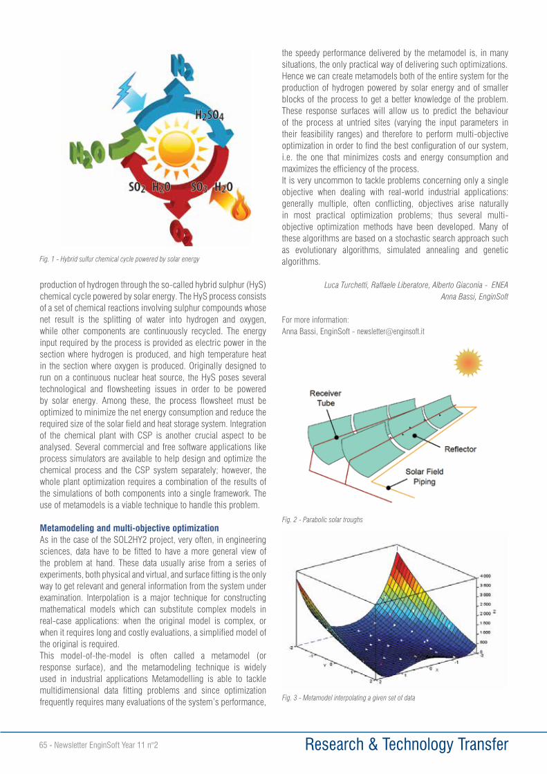
Research & Technology Transfer65 - Newsletter EnginSoft Year 11 n°2
production of hydrogen through the so-called hybrid sulphur (HyS) chemical cycle powered by solar energy. The HyS process consists of a set of chemical reactions involving sulphur compounds whose net result is the splitting of water into hydrogen and oxygen, while other components are continuously recycled. The energy input required by the process is provided as electric power in the section where hydrogen is produced, and high temperature heat in the section where oxygen is produced. Originally designed to run on a continuous nuclear heat source, the HyS poses several technological and flowsheeting issues in order to be powered by solar energy. Among these, the process flowsheet must be optimized to minimize the net energy consumption and reduce the required size of the solar field and heat storage system. Integration of the chemical plant with CSP is another crucial aspect to be analysed. Several commercial and free software applications like process simulators are available to help design and optimize the chemical process and the CSP system separately; however, the whole plant optimization requires a combination of the results of the simulations of both components into a single framework. The use of metamodels is a viable technique to handle this problem.
Metamodeling and multi-objective optimizationAs in the case of the SOL2HY2 project, very often, in engineering sciences, data have to be fitted to have a more general view of the problem at hand. These data usually arise from a series of experiments, both physical and virtual, and surface fitting is the only way to get relevant and general information from the system under examination. Interpolation is a major technique for constructing mathematical models which can substitute complex models in real-case applications: when the original model is complex, or when it requires long and costly evaluations, a simplified model of the original is required. This model-of-the-model is often called a metamodel (or response surface), and the metamodeling technique is widely used in industrial applications Metamodelling is able to tackle multidimensional data fitting problems and since optimization frequently requires many evaluations of the system’s performance,
the speedy performance delivered by the metamodel is, in many situations, the only practical way of delivering such optimizations.Hence we can create metamodels both of the entire system for the production of hydrogen powered by solar energy and of smaller blocks of the process to get a better knowledge of the problem. These response surfaces will allow us to predict the behaviour of the process at untried sites (varying the input parameters in their feasibility ranges) and therefore to perform multi-objective optimization in order to find the best configuration of our system, i.e. the one that minimizes costs and energy consumption and maximizes the efficiency of the process.It is very uncommon to tackle problems concerning only a single objective when dealing with real-world industrial applications: generally multiple, often conflicting, objectives arise naturally in most practical optimization problems; thus several multi-objective optimization methods have been developed. Many of these algorithms are based on a stochastic search approach such as evolutionary algorithms, simulated annealing and genetic algorithms.
Luca Turchetti, Raffaele Liberatore, Alberto Giaconia - ENEAAnna Bassi, EnginSoft
For more information:Anna Bassi, EnginSoft - [email protected]
Fig. 1 - Hybrid sulfur chemical cycle powered by solar energy
Fig. 2 - Parabolic solar troughs
Fig. 3 - Metamodel interpolating a given set of data
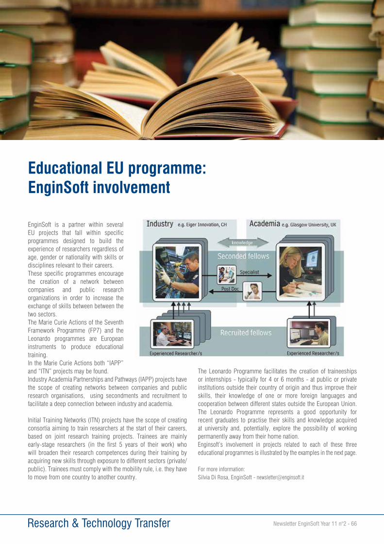
Research & Technology Transfer Newsletter EnginSoft Year 11 n°2 - 66
Educational EU programme: EnginSoft involvement
EnginSoft is a partner within several EU projects that fall within specific programmes designed to build the experience of researchers regardless of age, gender or nationality with skills or disciplines relevant to their careers.These specific programmes encourage the creation of a network between companies and public research organizations in order to increase the exchange of skills between between the two sectors.The Marie Curie Actions of the Seventh Framework Programme (FP7) and the Leonardo programmes are European instruments to produce educational training.In the Marie Curie Actions both “IAPP” and “ITN” projects may be found. Industry Academia Partnerships and Pathways (IAPP) projects have the scope of creating networks between companies and public research organisations, using secondments and recruitment to facilitate a deep connection between industry and academia.
Initial Training Networks (ITN) projects have the scope of creating consortia aiming to train researchers at the start of their careers, based on joint research training projects. Trainees are mainly early-stage researchers (in the first 5 years of their work) who will broaden their research competences during their training by acquiring new skills through exposure to different sectors (private/public). Trainees must comply with the mobility rule, i.e. they have to move from one country to another country.
The Leonardo Programme facilitates the creation of traineeships or internships - typically for 4 or 6 months - at public or private institutions outside their country of origin and thus improve their skills, their knowledge of one or more foreign languages and cooperation between different states outside the European Union. The Leonardo Programme represents a good opportunity for recent graduates to practise their skills and knowledge acquired at university and, potentially, explore the possibility of working permanently away from their home nation. Enginsoft’s involvement in projects related to each of these three educational programmes is illustrated by the examples in the next page.
For more information:Silvia Di Rosa, EnginSoft - [email protected]
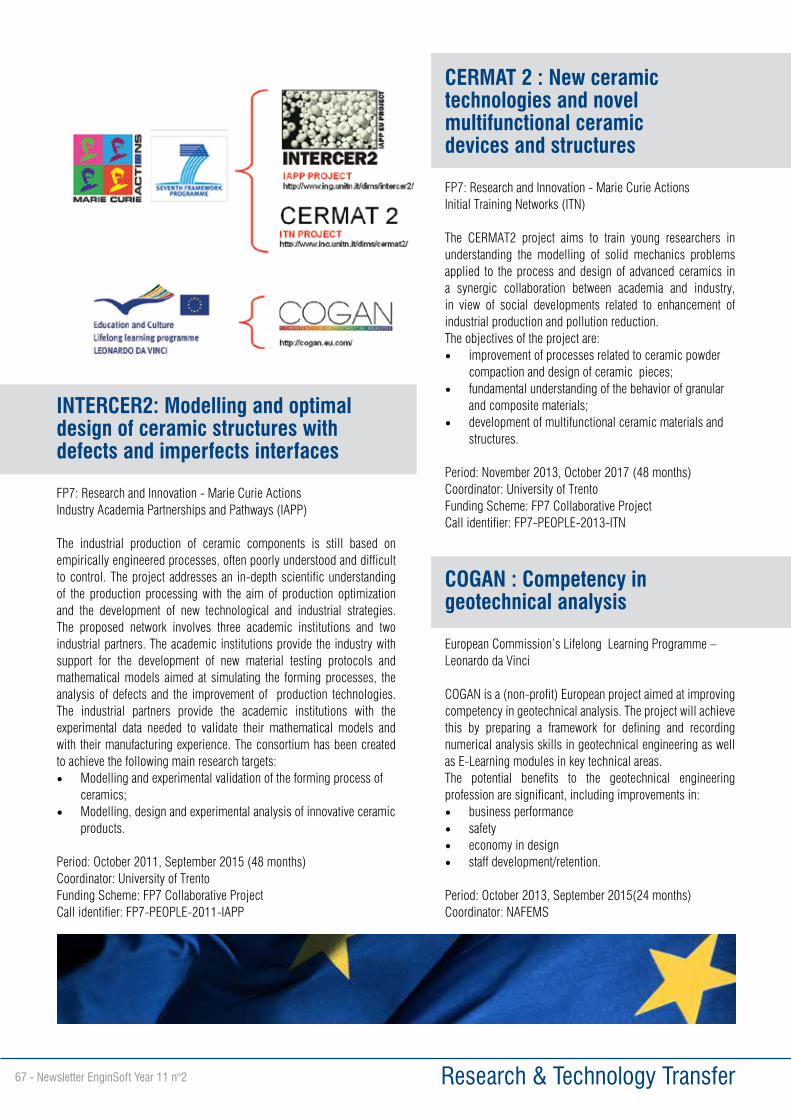
Research & Technology Transfer67 - Newsletter EnginSoft Year 11 n°2
CERMAT 2 : New ceramic technologies and novel multifunctional ceramic devices and structures
FP7: Research and Innovation - Marie Curie ActionsInitial Training Networks (ITN)
The CERMAT2 project aims to train young researchers in understanding the modelling of solid mechanics problems applied to the process and design of advanced ceramics in a synergic collaboration between academia and industry, in view of social developments related to enhancement of industrial production and pollution reduction.The objectives of the project are:• improvement of processes related to ceramic powder
compaction and design of ceramic pieces;• fundamental understanding of the behavior of granular
and composite materials;• development of multifunctional ceramic materials and
structures.
Period: November 2013, October 2017 (48 months)Coordinator: University of TrentoFunding Scheme: FP7 Collaborative Project Call identifier: FP7-PEOPLE-2013-ITN
INTERCER2: Modelling and optimal design of ceramic structures with defects and imperfects interfaces
FP7: Research and Innovation - Marie Curie ActionsIndustry Academia Partnerships and Pathways (IAPP)
The industrial production of ceramic components is still based on empirically engineered processes, often poorly understood and difficult to control. The project addresses an in-depth scientific understanding of the production processing with the aim of production optimization and the development of new technological and industrial strategies. The proposed network involves three academic institutions and two industrial partners. The academic institutions provide the industry with support for the development of new material testing protocols and mathematical models aimed at simulating the forming processes, the analysis of defects and the improvement of production technologies. The industrial partners provide the academic institutions with the experimental data needed to validate their mathematical models and with their manufacturing experience. The consortium has been created to achieve the following main research targets:• Modelling and experimental validation of the forming process of
ceramics; • Modelling, design and experimental analysis of innovative ceramic
products.
Period: October 2011, September 2015 (48 months)Coordinator: University of TrentoFunding Scheme: FP7 Collaborative Project Call identifier: FP7-PEOPLE-2011-IAPP
COGAN : Competency in geotechnical analysis
European Commission’s Lifelong Learning Programme – Leonardo da Vinci
COGAN is a (non-profit) European project aimed at improving competency in geotechnical analysis. The project will achieve this by preparing a framework for defining and recording numerical analysis skills in geotechnical engineering as well as E-Learning modules in key technical areas.The potential benefits to the geotechnical engineering profession are significant, including improvements in:• business performance• safety• economy in design• staff development/retention.
Period: October 2013, September 2015(24 months)Coordinator: NAFEMS
Corporate News Newsletter EnginSoft Year 11 n°2 - 68
EnginSoft becomes a member of ETP4HPC, the European Platform for HPC
Besides being active in PRACE, partner in FORTISSIMO and member of Ter@tec, EnginSoft is now full member of ETP4HPC, the European Platform for High Performance Computing (http://www.etp4hpc.eu). Entitled as high level stakeholder representing the industry at the Strategy Meeting on High Performance Computing (held by President Barroso), Enginsoft is once more in the heart of the innovative and challenging world of HPC.High Performance Computing (HPC) plays a pivotal role in stimulating Europe’s economic growth. HPC is a pervasive tool allowing industry and academia to develop world class products, services and inventions in order to maintain and reinforce
Europe’s position on the competitive worldwide arena. HPC is also recognized as crucial in addressing grand societal challenges.“Today, to Out-Compute is to Out-Compete” best describes the role of HPC. The platform ETP4HPC was born to define research priorities for the development of a globally competitive HPC technology ecosystem in Europe. It will act as the “one voice” of the European HPC industry in relations with the European Commission and National Authorities. Taking part to ETP4HPC, EnginSoft will contribute to creating new technologies within the entire HPC stack, to improve system characteristics, to deploy new fields for HPC and to expand HPC usage towards industry.Computational Science is the “third pillar” of science, increasingly based on data, simulation and models. Some examples are represented by brain models to fight diseases like Alzheimer or by new elementary particles studies. Industry, especially for manufacturing, oil & gas and pharmaceutical branches, day by day relies on HPC in order to innovate product and services.In this context, EnginSoft, with its long tradition and experience on solving complex and industrial problems, daily exploits the potential of HPC and is the bridge between new ICT performances and industry, able to drive the change towards exascale HPC.
For more information:Carla Baldasso, EnginSoft- [email protected]
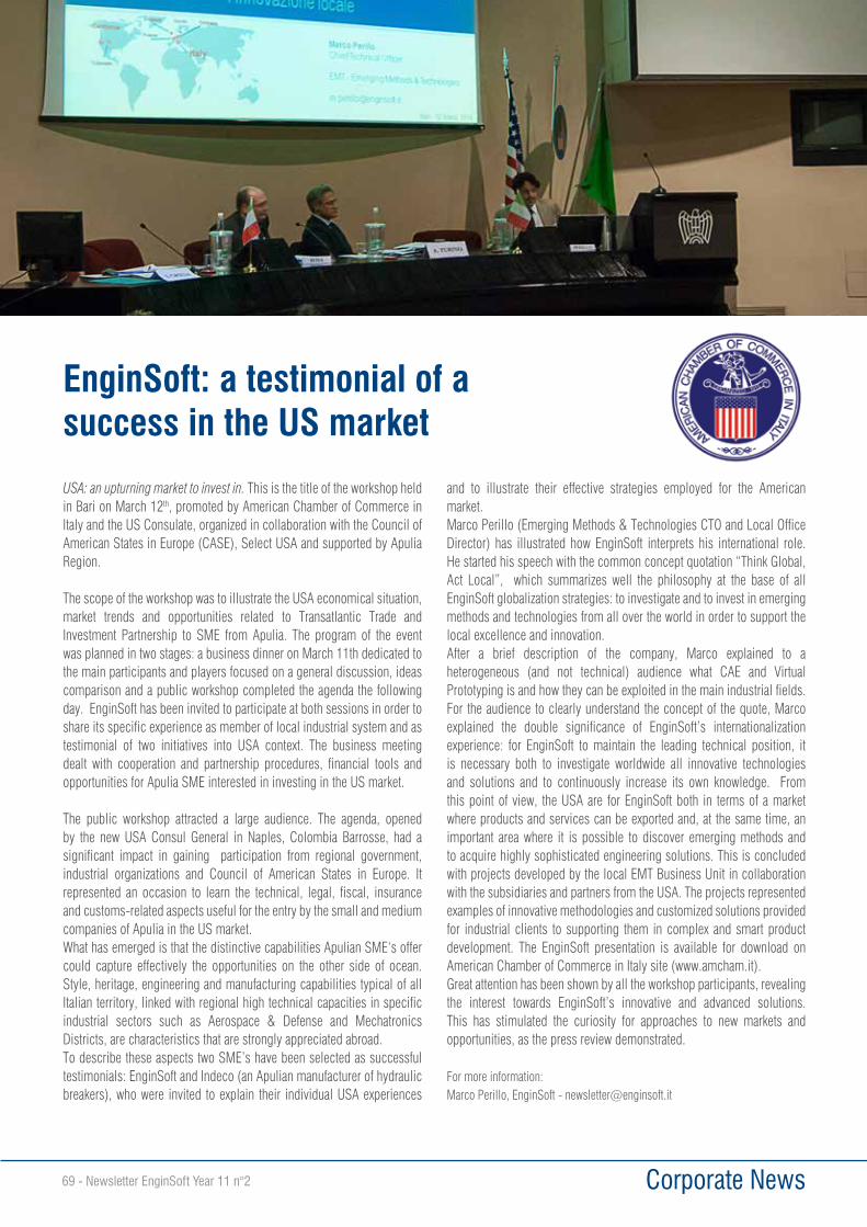
Corporate News69 - Newsletter EnginSoft Year 11 n°2
EnginSoft: a testimonial of a success in the US market
USA: an upturning market to invest in. This is the title of the workshop held in Bari on March 12th, promoted by American Chamber of Commerce in Italy and the US Consulate, organized in collaboration with the Council of American States in Europe (CASE), Select USA and supported by Apulia Region.
The scope of the workshop was to illustrate the USA economical situation, market trends and opportunities related to Transatlantic Trade and Investment Partnership to SME from Apulia. The program of the event was planned in two stages: a business dinner on March 11th dedicated to the main participants and players focused on a general discussion, ideas comparison and a public workshop completed the agenda the following day. EnginSoft has been invited to participate at both sessions in order toshare its specific experience as member of local industrial system and astestimonial of two initiatives into USA context. The business meeting dealt with cooperation and partnership procedures, financial tools and opportunities for Apulia SME interested in investing in the US market.
The public workshop attracted a large audience. The agenda, opened by the new USA Consul General in Naples, Colombia Barrosse, had a significant impact in gaining participation from regional government, industrial organizations and Council of American States in Europe. It represented an occasion to learn the technical, legal, fiscal, insurance and customs-related aspects useful for the entry by the small and medium companies of Apulia in the US market. What has emerged is that the distinctive capabilities Apulian SME‘s offer could capture effectively the opportunities on the other side of ocean. Style, heritage, engineering and manufacturing capabilities typical of all Italian territory, linked with regional high technical capacities in specific industrial sectors such as Aerospace & Defense and Mechatronics Districts, are characteristics that are strongly appreciated abroad. To describe these aspects two SME’s have been selected as successful testimonials: EnginSoft and Indeco (an Apulian manufacturer of hydraulic breakers), who were invited to explain their individual USA experiences
and to illustrate their effective strategies employed for the American market. Marco Perillo (Emerging Methods & Technologies CTO and Local Office Director) has illustrated how EnginSoft interprets his international role. He started his speech with the common concept quotation “Think Global, Act Local”, which summarizes well the philosophy at the base of all EnginSoft globalization strategies: to investigate and to invest in emerging methods and technologies from all over the world in order to support the local excellence and innovation.After a brief description of the company, Marco explained to a heterogeneous (and not technical) audience what CAE and Virtual Prototyping is and how they can be exploited in the main industrial fields.For the audience to clearly understand the concept of the quote, Marco explained the double significance of EnginSoft’s internationalization experience: for EnginSoft to maintain the leading technical position, it is necessary both to investigate worldwide all innovative technologies and solutions and to continuously increase its own knowledge. From this point of view, the USA are for EnginSoft both in terms of a market where products and services can be exported and, at the same time, an important area where it is possible to discover emerging methods and to acquire highly sophisticated engineering solutions. This is concluded with projects developed by the local EMT Business Unit in collaboration with the subsidiaries and partners from the USA. The projects represented examples of innovative methodologies and customized solutions provided for industrial clients to supporting them in complex and smart product development. The EnginSoft presentation is available for download on American Chamber of Commerce in Italy site (www.amcham.it). Great attention has been shown by all the workshop participants, revealing the interest towards EnginSoft’s innovative and advanced solutions. This has stimulated the curiosity for approaches to new markets and opportunities, as the press review demonstrated.
For more information:Marco Perillo, EnginSoft - [email protected]
Events Newsletter EnginSoft Year 11 n°2 - 70
Scilab is world’s most powerful open source software for numerical computation and simulation. It has been adopted within all the major strategic and scientific areas of industry and services, such as aerospace, automotive, electronics, energy, defense, finance, etc. Scilab provides a powerful computing environment for engineering and scientific applications:• Mathematics and simulation• 2D and 3D visualization• Optimization• Statistics• Control systems design and analysis• Signal processing• Application developmentXcos, distributed with Scilab, is an efficient graphical editor to model hybrid dynamic systems. Using Xcos, discrete and continuous systems can be designed, loaded, saved, compiled and simulated. Available blocks include signal processing, electrical, thermo-hydraulic, mathematics operations, and much more. Moreover, user-defined blocks can be easily added to the framework.The two-day ScilabTEC conference features a rich program of Scilab applications following an international call for papers; this event cements the position of Scilab as the reference open-source numerical computation and simulation tool within Europe and worldwide.ScilabTEC offers a unique opportunity for over one million Scilab users to discover the latest software developments, industrial applications and enhance their knowledge of Scilab and its ecosystem. The program includes presentations of Scilab industrial applications from MIT, INRA, AREVA, and many more.EnginSoft is proud to support the event’s main organizer, Scilab Enterprises, the official publisher of Scilab, founded by the Scilab Consortium which had previously developed the software since 2003. The event is sponsored by Inria, the French public research institute in computational sciences, who contribute to innovation within France by transferring its technologies and skills to industry.ScilabTEC 2014 will be held on May 15 and 16 at the Edouard VII Convention Center in Paris (FR).
For more information about the event visit:http://www.scilabtec.com
EnginSoft is one of the organizers of the ScilabTEC 2014, a two-day conference dedicated to Scilab
11-13 June 2014 - Fiera Verona - Pad. 4 B42
Starting from April 11th and for three days, Metef, Foundeq, Alumotive e Metalriciclo Recomat will host in their respective thematic halls, the most important international protagonists of the production and transformation of aluminum and innovative material, extrusion foundry and die-casting, lamination, finishing, recovery and recycle, machining, technologies and innovative materials for transport components.
The international expo, now at its 10th edition, thanks to this specific focus, is a unique event of its kind, dedicated to the metallurgic- manufacturing chain, a “made in Italy” excellence, a reference point for Italian and European economy, in a sector of great interest for new global growth economies.
The key aspect of the approaching edition is on innovative and tailor-made materials, technologies, machines and plants, to meet the users’ needs and the exhibiting companies represent the excellence in their respective sectors.
With a new all, devoted to Alumotive, it will be possible to see the novelties and innovative solutions addressed to suppliers of automotive first equipment, commercial and industrial vehicles, farm machines, earth moving machines, trains and underground railways.
EnginSoft will participate in the Innovation Award together with Sapp, presenting a project in which a specific procedure has been developed related to an engineering-technological analysis based on numerical simulation, with the aim of supporting and optimizing the advanced design of die-casting moulds and the related bearing structure (press and die holder).
For more information on the event:http://www.metef.com
EnginSoft participates in METEF 2014EnginSoft will as usual take part in the MEFET exhibition with its own booth, so to present the new releases of process simulation software and in particular the novelties concerning MAGMA 5 and MAGMA C+M

Events71 - Newsletter EnginSoft Year 11 n°2
2014 CAE EVENTS Stay tuned to:www.enginsoft.it/eventi - www.enginsoft.com/events/for the complete program of the events in 2014
EVENT CALENDAR
Your FREE Newsletter CopyDo you want to receive a free printed copy of the EnginSoft Newsletter?Just scan the QRcode or connect to: www.enginsoft.it/nl
CAE WEBINARS 2014
EnginSoft continues the proposal of the CAE Webinar on specific topics of the virtual prototyping technologies.
Next topics: Composities Materials, Scilab/Xcos, ANSYS FSI, Engine design, ANSYS CFD Multiphase, Multiphysics analysis in ANSYS 15.0, Injection Molding...
Stay tuned to www.enginsoft.it/eventifor the complete program of webinars. The podcasts on past CAE Webinars are available at: www.enginsoft.it/eventi
June 11-13, 2014 Verona, ItalyMETEF 2014 http://www.metef.comExpo of customized technology for the aluminium&innovative metals industry. EnginSoft will be present with a booth Pad. 4 B42
October 27-28, 2014 Torino, ItalyInternational CAE Conference http://www.caeconference.comEnginSoft will be the main sponsor of the International CAE Conference. Many of our engineers will be engaged in presenting industrial case stories during the parallel sessions of the Conference and technology updates during the workshops.May 27-28, 2014 Graz, Italy
Graz Symposium Virtuelles Fahrzeug http://gsvf.at/cms/The Interdisciplinary Development of Road and Rail Vehicles symposium, provides to the participants Processes, Methods, Tools, Best Practices aimed to develop the next coming vehicle. EnginSoft will be exhibiting at our dedicated booth and presenting a paper at the event.
May 23-24, 2014 ItalyANSYS Users MeetingThis is the dedicated ANSYS Users Meeting for Italian users. EnginSoft, as ANSYS Italian Channel Partner, will foster the initiative to provide participants with the latest developments and overview of Release 15.0.
June 10-11, 2014 Oxford, UKNAFEMS UK Conference 2014: Accelerating the Future of CAEhttp://www.enginsoft.com/uk/events/nafems-uk-conference-2014.htmlVisit EnginSoft at the NAFEMS UK Conference in Oxford and meet our experts in complex simulation to find out how we can assist you.
June 8-13, 2014 Otranto, ItalyInternational Conference on Water TreatmentWastewater and biosolids treatment and reuse - Bridging Modeling and Experimental Studies.
July 1-2, 2014 FranceTERATEC PARIGIhttp://www.teratec.eu/gb/forum/The international meeting for Simulation and High Performance Computing.
COME TO MEET US AT:

Turin, ItalyOctober 27-28, 2014
Your opportunityto be part
of the future!
Striving for innovation excellence?
Join the thought-leaders at the world’s largest gathering of Simulation Based Engineering and Science
Call for Papers is now open!
A great opportunity to submit an abstract and share your expertise
www.caeconference.com