manufacturing dental implants using powder...
TRANSCRIPT

iMedPub Journalshttp://www.imedpub.com
2016Vol. 2 No. 1:21
1© Copyright iMedPub This article is available in http://orthodontics-endodontics.imedpub.com/
Research Article
Journal of Orthodontics & Endodontics ISSN 2469-2980
Ferreira TJ1, Vieira MT1,Costa J2, Silva M3 andGago PT3
1 CEMUC – Centro de Engenharia Mecânica da Universidade de Coimbra, Portugal
2 IPN–InstitutoPedroNunes,Coimbra,Portugal
3 3DTech – Marinha Grande, Portugal
Corresponding author: Ferreira TJ
CEMUC – Centro de Engenharia Mecânica daUniversidadedeCoimbra,Portugal.
Tel: +351 239 700 967
Citation: Ferreira TJ, Vieira MT, Costa J, et al. Manufacturing Dental Implants usingPowder InjectionMolding. JOrthodEndod.2016,2:1.
Manufacturing Dental Implants using Powder Injection Molding
AbstractDuring the last decennia it is demonstrated that the injection molding usedin polymers could be the solution to decrease the price of parts / devices ofmetallic alloys for large-scale series production. The metal powder injectionmolding (MIM) techniquehasfivemain steps: selectionofpowderandbinder,productionoffeedstock,injectionmolding,debindingandsintering.Thematerialselected was the 316L steel due to its wide use as biomaterial associated to low costofpowdersand itshigh injectability.The feedstockwassuitableoptimizedandproducedby torque rheometry technique.The ideal feedstockhas60:40%vol. of powders:binder andhas low torque value (suitable to injection step). Itisimportanttodecreasethefrictioncoefficient(betweenthemoldingpartsandmoldsurfaces)andto improvesignificantlythewearstrengthofmoldsurfaces.The(micro)moldwasdesignedanddevelopedforproducingdental implantsinlargeseriesthatmeanscoatedwithahighhardnessandnearfrictionlessthinfilmofdichalcogenidessulphides(W-S-C).Theinjectionstepwascarriedoutat10MPaandthebinderwasefficientlyremovedfromgreenimplants.Aftersinteringstep(at 12500C), dental implants have a goodfinishing and the shrinkageof dentalimplants was evaluated. The osseointegrability was promoted by coating thesinteredimplantswithathinfilmofnon-modifiedandSimodifiedhydroxyapatite(HA).Thecoateddentalimplantsweremechanicallyevaluatedduringimplantationusingabovinerib.Thenewstrategicproduction leadscheaper implants,called"implants for crisis", where surface modification assures a similar or superiorbioactivitythancommercialimplants.
Keywords: Powderinjectionmolding;Dentalimplants;316Lpowders;Micromold;W-S-Ccoating;HAthinfilms
Received: December09,2015; Accepted: February18,2015; Published: February22,2016
IntroductionDentalimplantsexistedformanyyearsandtheyincludeartificialteeth to restore the natural dental function [1]. Conventionaldental implants are typically made in metal and metal alloys,where titanium and its alloys have an important role. Besidesthehigh cost of thesematerials, the traditionalmanufacturingsystemsareexpensivehavinginmindthenumberofimplantstobeproducedandtheircomplexshape[2].
Currently, there isaneedto improvethemethodmanufactureofdentalimplants,makingthemcheaperandfastmanufacturing[1].Inordertoinvestigatealternativecosteffectivemanufacturingmethods for producing dental implants, MIM technique wasevaluated. TheMIM is regardedas verypromisingnet shaping
technique,duetoitsadvantagesforcomplexgeometry,precisionand production in large-scale series of implants with highperformance,withoutfinishingprocess[3].TheMIMtechniquehavefiveprocessingsteps,namely:rawmaterialcharacteristics(4S's=particlesize,particledistributionsize,shapeandstructure),mixingofpowderandbinderforfeedstockpreparation,injectionmoldingoffeedstocktothedesiredshape,debindingtoremovethe binder and sintering to give the required properties [3-5].The thermalcharacterizationofthebinder isvery importanttoknowthemeltinganddegradationtemperatures, todefinetheprocessing conditions for mixing and injection, as well as fordebindingcycle.Inthefeedstockpreparationisessentialthatallthe metallicpowdersareinvolved/coatedbybinderandsuitableviscosityforoneinjectionstepadequate.Thebindercontentin

2
ARCHIVOS DE MEDICINAISSN 1698-9465
2016Vol. 2 No. 1:21
©CopyrightiMedPub Thisarticleisavailableinhttp://orthodontics-endodontics.imedpub.com/
Journal of Orthodontics & Endodontics ISSN 2469-2980
feedstockmustbeoptimizedinordertohaveasuitableviscosityvalueandafterinjectionanddebinding(necessarytoproduceametallicpart/device)tomaintainthegeometrybeforesintering.
Among the big challenges facing MIM, the (micro) mold isunquestionablyoneofthemostrelevant,becauseofitsqualitydepends on the success or failure of this technology. Themolding blocks for injectionmolding, usually consist in inserts(cavityandcore)micro machined and assembled on a standard structure.Whilethemold’sstructureanditsinjectionsystemsaremanufacturedby conventionalprocesses,other techniquesareusedformanufacturingthemoldingsurfaces.Themanufactureof(micro)moldsusessubtractivemicromachiningtechnologiesthat can create 3D micro geometries, in some cases, with high-precision and aspect ratio, like micro-milling, laser beammachining (LBM), micro electric discharge machining (µEDM)and,aspolish/finishtechnology,electronbeammachining(EBM)[6]. All of these techniques,micro-milling is themost versatileandabletoproducecomplex3Dshapes,butquiteproblematicindetailsbelowthan0.1mm.TheµEDMand,especiallytheLBM,will produce a thermal affected layer, therefore not ensuringthedesirable textureand integritysurface for thegeneralityofapplications,butthis limitationcanberesolvedwiththeuseofEBM.NotethatfinishingbyEBMpromotessignificantresistanceto oxidation and corrosion,when comparedwith conventionalsurfacetreatmentprocesses[7].
One of the critical steps of injectionmolding is the extractionof the implant from(micro)cavity.During theextractionsteps,thepartsaremechanicallyforcedtoseparatefromthemoldingsurface and this aspect is more relevant in the case of deepcavities. Thedesignof theejection systemdependson severalfactors:draftangles,surfacefinishing,propertiesofthematerialtoinjectandtemperatureduringtheejectionstep[8].
Othermain existing problems in themanufacture of the teethimplantsisbasedontheabilitytoprocesshighqualitysurfaceswith minimal roughness values associated to the dimensional precisiontolerances,whicharefundamentaltothemicroscale.Moreover, the injection ofmetallic feedstock ismore abrasivethan the polymeric ones, which difficult the outflow duringinjection and consequently, the extraction process of smallcomponents. In order to overcome this critical issue, coatingsreferredtoas“near-frictionless”asDichalcogenidesSulphidesare an optimal solution [9, 10]. They arewell known for theircrucial role in reduction ofmechanical and abrasivewear andbyexhibit lowfrictioncoefficient,which isrelevanttopromotetheextractionfromthecoatedmoldofimplants.Thesputteringtechnology used on the development of this type of coating,whichbelongstothegroupofadditiveprocessescalledPhysicalVapor Deposition (PVD), is a versatile technology that enablesdeveloping coatings with suitable chemical compositions andhomogeneous growth over surfaces to protect /modify them,responding effectively to the challenges in themanufacture ofmoldsformicro-componentsormoldswithmicrodetails.
The MIM technology can help to produce cheap dentalimplants, however it can be necessary to improve the rateof osseointegration e.g. through implants coated with nanohydroxyapatite(nanoHA)withorwithoutsiliconaddition.There
are studies reporting that HA doped with specific elements(titanium)hasadvantageinbiologicalprocess[11,12].Therefore,HAbasedcoatingswereselectedduetotheirgoodperformanceinosseointegrationbehaviour.
Themainobjectiveofthepresentstudyistoshowthepotentialofinjectiontechnologyforproducingmetallicdentalimplantsfrommetallicpowders,highlightingtheengineeringsolutionsforthemanufactureofmicro-moldscoatedwithW-S-Cto improvetheperformanceofejectionstepandminimizetheforcetoseparatethe parts from the molding surface. Were produced dentalimplantsbyMIMfrompowdersofausteniticstainlesssteel (SS316L).Thesintereddentalimplantswerephysicalandmechanicalcharacterisedandthetorquestrengthofimplantswasevaluatedusingascounterbodyabovinerib.ThedentalimplantsproducedwerecoatedbynanoHAwithvariouscontentsofsilicon.
Materials and MethodsMaterialsIn thiswork, themetalpowderusedwaswateratomized316Laustenitic stainless steel - SS316L (Epson Atmix Corporation®)andthemulti-polymericbinderbasedonpolyolefinwaxes(fromAtect®).Thematerialusedforproducingthe(micro)moldwasasteelDINX40CrMoV51(48to52HC).
Themolding blockswere coatedwithDichalcogenide SulphidecoatingW-S-C.Theyweredepositedbyco-sputtering fromtwoWS2andoneCarbontargetsinanunbalanced-sputteringunity(Teer coating equipment). A fourthChromium target was used as interlayer step, inorder to improve thecoatingadhesion toSSsubstrate.Finally,dentalimplantswerecoatedfromHAtargetusingrfsputtering.
MethodsThe mixture of metallic powder and binder was optimized bytorquerheometrytechniqueinBrabenderPlastographmixer,forsuitableevaluationofthecriticalpowdervolumeconcentration(CPCV), at programmed temperature and rotational speed [5].Afteroptimization,itwaspossibletoselectthesuitablepowder:binder ratio for produce feedstock and this was evaluated bycontrollingthetorquevalueduringthemixtureprocessandbySEMmicrographs.Finally,thefeedstockwasgranulatedintosmallgranules promoting the homogeneity and enabling feedwhencarriedouttheinjectionmolding,intoamoldcavitywithshapeofdentalimplantsinArburg270Cinjectionmoldingmachine.Thedebindingandsinteringthermalcycles,werecarriedoutinahightemperatureoven, under controlled atmosphereof 95%argonand 5% hydrogen. The debinding cycle was based on binderthermal analysis and the sintering conditionswere carried outaccordingtotheselectedpowder.
The µmold was produced by the following subtractivetechnologies:µmilling,µEDMandEBM.Theµmillingmachiningwasperformedonhigh-speedCNCmicro-machine(DeckelMahoGildmeister),withamaximumspindlespeedof36000rpm.Thecutting tools (Hitachi) were of fine-grained tungsten carbide,coated with TiAlN for a better preservation of cutting edges.Erro!Aorigemdareferêncianãofoiencontradasummarizethe
3
ARCHIVOS DE MEDICINAISSN 1698-9465
2016Vol. 2 No. 1:21
©CopyrightiMedPub Thisarticleisavailableinhttp://orthodontics-endodontics.imedpub.com/
Journal of Orthodontics & Endodontics ISSN 2469-2980
cutting andmachine configuration parameters used.On sinkermicro-electricdischargemachininganAgieequipmentwasused,where the generator was able to supply between 0.8 and 64Amperesandhad thepossibility toadjust thepulseandpausetimesbetween1and7500µs.Thevoltagevariationrangeofthisequipmentwasfrom60to250Volts.Thecontroller’sresolutionwas set to 0,001 mm. The electrodes were manufactured byμmillinginfine-grainedgraphiteforabetterfinishandaccuracy(graphitehasahighermeltingpointthancopperandsupportsahigherenergydensity).TheclampingandpositioningsystemsontheCNCandEDMmachineswereoftheErowabrand.PolishingusinganelectronbeamwasperformedinaPikaFinishmachinefromSodick,withabeamdiameterof60mm.
The sputtering equipment used in the production of W-S-Ccoatings was a semi-industrial model UDP 650 Teer CoatingsLtd. The molding blocks were previously cleaned with alcohol andacetonebyultrasoundsandplacedona rotating table (10rotations per minute) inside the vacuum chamber, and then evacuatedtoanultimatevacuumpressureoflessthan1×10−3 Pa.BeforeW-S-Cdepositionwasperformedanetching step toeliminateresidualcontamination.
The dental implants produced were coated with thin films ofhydroxyapatite (HA) and hydroxyapatite doped with differentsilicon contents (HASi). These coatings were sputtered on asurface of dental implant using a rf magnetron sputteringequipment (Edwards Coating System E306A) and argon as thesputtergas(depositionparameters:d=32×10-2W/mm2;P=1.2Pa;t=5400s).ForthedopedthinfilmstheHAtargetwaspatchworkedwith2and4siliconwafers.
Themechanicalcharacterizationofdentalimplantswasachievedafter an insertion torque test using a surgical hand-piecewithamultiplyingrateof32:1mountedonaSEMNouvag®surgicalunitwithtorquecontrolthatwasperformedbyanimplantologist(through torque strength test and used diverse surgical equipments: surgicalmotor – NOUVAG SEM,micro-motor andcontra-angle – NOUVAG 32:1). The structure of the coatingsimplantswasanalyzedbyXRD.
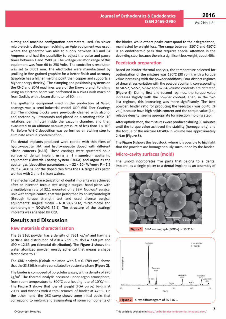
Results and DiscussionRaw materials characterizationTheSS316Lpowderhasadensityof7961kg/m3 and having a particle sizedistributionofd10=2.99μm,d50=7.68μmandd90=12.63μm(bimodaldistribution).TheFigure 1 shows the water atomized powder, mostly spherical that means a shapefactorcloseto1.
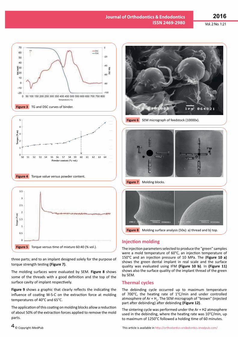
The XRD analysis (Cobalt radiationwith λ = 0.1789nm) showsthattheSS316Lismainlyconstitutedbyaustenitephase(Figure 2).
Thebinderiscomposedofpolyolefinwaxes,withadensityof970kg/m3.Thethermalanalysisoccurredunderargonatmosphere,fromroomtemperatureto800°Cataheatingrateof10°C/min.The Figure 3 shows that loss of weight (TGA curve) begins at200°Candfinisheswitha total removalofbinderat475°C.Onthe other hand, the DSC curve shows some initial peaks thatcorrespondtomeltingandevaporatingofsomecomponentsof
thebinder,whileotherspeakscorrespondtotheirdegradation, manifestedbyweightloss.Therangebetween350°Cand450°Cis an endothermic peak that requires special attention in thedebindingstep,becausethereisasignificantlossweight,about40%.
Feedstock preparationBasedonbinderthermalanalysis,thetemperatureselectedforoptimizationof themixturewas180°C (30rpm),witha torquevalueincreasingwiththepowderadditions.Fourdistinctregimesofshearstressvariationwiththepowderscontent,correspondingto50-52,52-57,57-62and62-64volumecontentsaredetected(Figure 4). During first and second regimes, the torque valueincreases slightly with the powder content. Then, in the twolast regimes, this increasing was more significantly. The bestpowder:binderratioforproducingthefeedstockwas60:40(%vol.)becausehavehighsolidscontentandthetorquevalue(i.e.,relativedensity)seemsappropriateforinjectionmoldingstep.
Afteroptimization,themixtureswereproducedduring30minutesuntilthetorquevalueachievedthestability(homogeneity)andthetorqueofthemixture60:40%involumewasapproximately2N.m(Figure 5).
The Figure 6showsthefeedstock,whereitispossibletohighlightthatthepowdersarehomogeneouslysurroundedbythebinder.
Micro-cavity surfaces (mold)The μmold incorporates five parts that belong to a dentalimplant,asasinglepiece;toadentalimplantasanassemblyof
SEMmicrograph(5000x)ofSS316L.Figure 1
20 40 60 80 100 1202 θ(°)
Inte
nsity
(a.u
.)
Austenite
Austenite A - AusteniteF - Ferrite
(200)
(220)
(111)
F (110)
F (200) F (211)(222)
(311)Austenite Austenite
Austenite
X-raydiffractogramofSS316L.Figure 2
4
ARCHIVOS DE MEDICINAISSN 1698-9465
2016Vol. 2 No. 1:21
©CopyrightiMedPub Thisarticleisavailableinhttp://orthodontics-endodontics.imedpub.com/
Journal of Orthodontics & Endodontics ISSN 2469-2980
threeparts;andtoanimplantdesignedsolelyforthepurposeoftorquestrengthtesting(Figure 7).
Themolding surfaceswere evaluated by SEM. Figure 8 shows someof the threadswithagooddefinitionand the topof thesurfacecavityofimplantrespectively.
Figure 9showsagraphicthatclearlyreflectsthe indicatingtheinfluence of coatingW-S-C on the extraction force at moldingtemperaturesof40°Cand65°C.
Theapplicationofthiscoatingonmoldingblocksallowareductionofabout50%oftheextractionforcesappliedtoremovethemoldparts.
Injection moldingTheinjectionparametersselectedtoproducethe"green"sampleswereamold temperatureof60°C,an injection temperatureof150°C and an injection pressure of 10MPa. The (Figure 10 a) shows the green dental implant in real scale and the surfacequality was evaluated using IFM (Figure 10 b). In (Figure 11) showsalsothesurfacequalityoftheimplantthreadofthegreenbySEM.
Thermal cyclesThe debinding cycle occurred up to maximum temperatureof 700°C, the heating rate of 1°C/min and under controlledatmosphereofAr+H2.TheSEMmicrographof"brown"(injectedpartafterdebinding)afterdebinding(Figure 12).
ThesinteringcyclewasperformedundertheAr+H2atmosphere usedinthedebinding,wheretheheatingratewas10°C/min,uptomaximumof1250°Cfollowedaholdingtimeof60minutes.
70
60
50
40
30
20
10
0
-10
-200 50 100 150 200 250 300 350 400 450 500 550 600 650 700 750 800
Temperature [°C]
0
-20
-40
-60
-80
-100
TGandDSCcurvesofbinder.Figure 3
5
4
3
2
1
050 51 52 53 54 55 56 57 58 59 60 61 62 63 64
Powder content (% vol.)
Torq
ue (N
.m)
Torquevalueversuspowdercontent.Figure 4
3.5
3
2.5
2
1.5
1
0.5
0
-0.50 5 10 15 20 25 30 35
Torq
ue (N
.m)
Time (min)Torqueversustimeofmixture60:40(%vol.).Figure 5
SEMmicrographoffeedstock(10000x).Figure 6
Moldingblocks.Figure 7
Moldingsurfaceanalysis(50x):a)threadandb)top.Figure 8
5
ARCHIVOS DE MEDICINAISSN 1698-9465
2016Vol. 2 No. 1:21
©CopyrightiMedPub Thisarticleisavailableinhttp://orthodontics-endodontics.imedpub.com/
Journal of Orthodontics & Endodontics ISSN 2469-2980
After sintering, the commonaspectof the implant is shown in(Figure 13 a)andthemorphologydetailsbyIFMin(Figure 13 b).Duringdebindingandsinteringsteps,thedentalimplantssufferedshrinkageof 13%up to 14% (Figure 14). It is also noteworthy,thatthesurfacequalityofthefinaldentalimplantshadabrightaspect,similartoapolishingsurface.
Osseointegrator thin filmOnce mechanically suitable to be implanted in bone, dentalimplantsmustpresentasurfacewithosseointegrationfeatures.Therefore thedental implantswerecoatedwith three typesofthinfilms,withorwithoutsiliconadditions(HA,HASi(2)andHASi(4)).TheX-raydiffractograms(Figure 15)revealedsomediffractionplanesthatcouldbeidentifiedasHA,accordingtoICDDcard09-0432.ThischaracterizationhighlightthenanocrystallinestructureofthemonolithicHAthinfilmandhighlightstheamorphizationofthethinfilmofHAwiththeintroductionofSi.
Tests in vitro of several HA modified by Si has a betterosseointegration[12].
Evaluation mechanical strength during implantationIn order to guarantee the good performance during theimplantationoftheSS316Lcoatedimplantaninsertiontorquetestwas carried out. Thiswas performed by an implantologistthat used drills of different diameters (2.2; 2.8 and 3.5 mm)sequentially, with rotation speed of 850 rpm to prepare theimplantbed(Figure 16).Inordertocreateaspiraltointroducethe implant, it was used another drill with 4.1 mm diameter(similar todiameterof dental implant) and a speedof 30 rpm (Figure 16).Figure 17showsthefinaldentalimplantstested. "Green"andfinaldentalimplants.Figure 14
1600
1400
1200
1000
800
600
400
200
0
Extr
actio
n Fo
rce
(N)
40°C 65°C
Uncoated
W-S-C coating
Variationoftheextractionforceofmoldingblockswithtemperature(feedstockA).
Figure 9
"Green"implanta)inrealscaleandb)analyzedbyIFM.
Figure 10
Implantthread"green"(SEM35x).Figure 11
SEMmicrographof"brown"component(3500x).Figure 12
a)Netshapeimplantandb)ImplantviewbyIFM.Figure 13
6
ARCHIVOS DE MEDICINAISSN 1698-9465
2016Vol. 2 No. 1:21
©CopyrightiMedPub Thisarticleisavailableinhttp://orthodontics-endodontics.imedpub.com/
Journal of Orthodontics & Endodontics ISSN 2469-2980
Abovineribwasselectedforthistestdueto itscorticalandspongy regions, to be similar to a human mandible bone -equivalent tobone type2 (Figure 18 a). The sintered dental implant was introduced in rib with speed of 30 rpm andthemaximum torquewas less than 0.27 N.m (Figure 18 b).Afterremovaltheimplantsfromtherib,theywerephysicallyunchanged, which means that the material adequatelysupportedtheinsertionforcesandforthatmaybeacceptablefor this application (Figure 18 c). The test showed thatdental implants produced from SS 316L powders byMIM ismechanicallysuitableforthisapplication.
Anewwaytoproducinggreatseriesdentalimplantsthatmeansfaster and cheaper than the conventional manufacturingprocessesisdemonstrated.
ConclusionTheMIMissuitabletoproducedentalimplants.Themoldingblocks coated with dichalcogenides sulphides thin filmsdecreasefrictionbetweeninjectedfeedstockandmolsurfaceand consequently is needed low forces during the moldextraction, which will increase the lifetime of the molding.Moreover,thecoatingprovidesbetterwearstrengthessentialtomaintainmicro-cavitiesand/ormicro-detailswithaconstantgeometry.Thesurfaceofsintereddentalimplanthasabrightaspectandagoodworkmanshipwhichmeansthatprocessingconditions were correctly selected. However, an implant inSS 316L has not a good osseointegration, to overcome thisproblem; the presence of a coating thatmust promote thismechanism is a good option. Thin films of hydroxyapatitedopedwithsiliconimprovethebioactivity.The316Lausteniticstainless steel and the process selected are appropriatefor dental implants and this was demonstrated by torquestrength test. Inconclusion,anewstrategy isopenedup formanufacturing the least expensive dental implants, called"implantsforcrisis".
AcknowledgementThe research is integrated in theproject BePIM through theprogramQREN,FEDER(COMPETE),BePIM2,ToolingSurface.FCTfortheSFRH/BD/86216/2012grant.
10 20 30 40 50 60 70 80
Inte
nsity
HASi(4)
HASi(2)
HA
S S
HA: ICDD 09-0432
S- Substrate
2 θ(°)
X-raydiffractogramofdifferentcoatings.Figure 15
Drillsused.Figure 16
Finaldentalimplantstested.Figure 17
a)Bovinerib,b)withimplantsandc)withoutimplants.
Figure 18
7
ARCHIVOS DE MEDICINAISSN 1698-9465
2016Vol. 2 No. 1:21
©CopyrightiMedPub Thisarticleisavailableinhttp://orthodontics-endodontics.imedpub.com/
Journal of Orthodontics & Endodontics ISSN 2469-2980
References1 CombiningthebestthatPIMhastooffertoputthebiteonanew
approach(2006)MetalPowderReport.November,pp:22-27.
2 HaackJ,ImgrundP,HeinS,FriedericiV,SalkN(2010)Theprocessingof biomaterials for implant applications by powder injectionmoulding.PowderInjectionMouldingInternational4:49-52.
3 Meng J, Loh NH, Fu G, Tor SB, Tay BY (2010) Replication andcharacterizationof316Lstainlesssteelmicromixerbymicropowderinjectionmolding.JournalofAlloysandCompounds496:293-299.
4 HeaneyDF(2012)Handbookofmetalinjectionmoldings:l.
5 Barreiros FM, Vieira MT, Castanho JM (2009) Fine tuning injectionfeedstockbynanocoatingSSpowder.MetalPowderReport64:18-21.
6 Giboz J, Copponnex T, Mele P (2007) Microinjection molding ofthermoplastic polymers: a review. Journal ofMicromechanics andMicroengineering17:R96-R109.
7 SeladaA,ManaiaA,VieiraMT,PouzadaAS(2011)EffectofLBMandlarge-areaEBMfinishingonmicro-injectionmouldingsurfaces.Int.J.AdvancedManufacturingTechnology52:171-182.
8 Pouzada AS, Ferreira EC, Pontes AJ (2006) Friction properties ofmouldingthermoplastics.PolymerTesting25:1017-1023.
9 Polcar T, EvaristoM, Cavaleiro A (2009) Comparative study of thetribologicalbehaviorofself-lubricatingW-S-CandMo-Se-Csputteredcoatings266:388.
10 PolcarT,CavaleiroA(2011)Self-adaptivelowfrictioncoatingsbasedontransitionmetaldichalcogenides.ThinSolidFilms519:4037–4044.
11 Ribeiro AR, PiedadeAP, Ribeiro CC, VieraMT, BarbosaMA (2007)Characterization of hydroxyapatite sputtered films doped withtitanium.KeyEngineeringMaterials330-332:649-652.
12 FernandesPC,FernandesMH,PiedadeAP(2014)MG63osteoblasticcellsandsilicondopedHAthinfilms.ActaMaterialia.