lateral stability of high-speed trains at unsteady crosswind274978/fulltext01.pdf · lateral...
TRANSCRIPT
Lateral Stability of High-Speed Trainsat Unsteady Crosswind
DIRK THOMAS
Licentiate Thesis in Railway TechnologyStockholm, Sweden 2009
Typeset in LATEX
TRITA-AVE 2009:79ISSN 1651-7660ISBN 978-91-7415-473-3
� Dirk Thomas, October 2009
KTH Engineering SciencesDep. of Aeronautical and Vehicle Engineering
Centre for ECO2 Vehicle Design/Division of Rail Vehicles
SE-100 44 StockholmSWEDEN

In memoriamChristine Schneider

Preface
This thesis summarizes the work carried out during my licentiate studies at theDepartment of Aeronautical and Vehicle Engineering at the Royal Institute ofTechnology (KTH) in Stockholm, Sweden.
It is part of the research project ”Crosswind Stability and Unsteady Aerodynamicsin Vehicle Design” within the VINNOVA Centre of Excellence for ECO2 VehicleDesign. The financial support from the centre is gratefully acknowledged.
I would like to thank my main supervisor Prof. Mats Berg for accepting me as PhDstudent and his guidance, support and comments since the beginning of the projectas well as the in-depth reviews of the manuscripts. In addition, many thanks to myco-supervisor Dr.-Ing. Sebastian Stichel for support and comments on the work. Ialso enjoyed working with our co-author Dr. Ben Diedrichs. Thanks Ben for fruitfuldiscussions and good collaboration.
My colleague within the project Tristan Favre is acknowledged for the co-operationduring the work on the literature survey.
Thanks to the steering group of the ECO2 crosswind project, consisting of SebastianStichel (Bombardier Transportation), Tohmmy Bustad (Banverket), Peter Erikssonand Per Elofsson (Scania CV), Hakan Danielsson (Saab Automobile), Pereric Wester-gren (Vagverket) as well as Mats Berg, Annika Stensson Trigell and Gunilla Efraims-son (all KTH), for comments on the work and participation.
Dr.-Ing. Christoph Weidemann from Intec GmbH is acknowledged for his supportwhen I was struggling with the software SIMPACK from time to time.
Thanks to all my colleagues at the Division of Rail Vehicles and within the Centreof ECO2 Vehicle Design for a nice working environment.
Very special thanks to my family in Germany and to my friends, mostly in Germanyand Sweden, but now also more distributed around the world in Chile, the USAand Tanzania.
Stockholm, October 2009
Dirk Thomas
v
The Swedish Licentiate degree may need an explanation for readers outside of Sweden.An intermediate academic degree called Licentiate of Technology can be obtainedhalfway between an MSc and a PhD. The examination for this degree is less formalthan for a PhD but it requires the completion of a thesis and a public seminar.
vi
Abstract
Crosswind stability of rail vehicles has been a research area for several decades,mainly motivated by vehicle overturning accidents and higher speeds, but in re-cent times also by issues of lower energy consumption and track maintenance costsdemanding lower vehicle weights. During everyday operation, rail vehicles are sub-jected to large lateral influences from track irregularities, track curves and cross-wind, leading to large suspension deflections and increased crosswind sensitivity.Also unsteady crosswind like gusts calls for attention. Simulations of possible vehi-cle overturning are necessary, but need to take large deflections and high shear inthe suspension into account. If delivering reasonable results, simulations representan important tool for overturning prediction of the vehicle.
In the present work, multibody simulations of a high-speed vehicle at large lateralinfluences from track curves and track irregularities have been carried out, using ahalf-vehicle model in 2D and a model of a whole vehicle in 3D. The vehicle mod-els also include different suspension models. Corresponding field measurements ofthe relative lateral and vertical deflections in the secondary suspension have beenperformed on a fast train and used for validation of the multibody simulations,resulting in good agreement between measurements and simulations.
The 3D vehicle model was further used to study the vehicle response to unsteadycrosswind during curve negotiation where aerodynamic loads obtained by unsteadyComputational Fluid Dynamics, namely Detached Eddy Simulations, representingthree types of gusts were used. In addition, the method of Quasi Transient GustModelling was evaluated in terms of overturning risk. Strong lateral and roll re-sponses of the vehicle and influences of the gust duration and the relative differencebetween mean and maximum wind speed were observed. Further, variations of sus-pension and mass properties of the vehicle were performed to study the influenceon crosswind sensitivity. The position of the centre of mass of the carbody and thelateral bumpstop clearance showed significant influence on the crosswind stability.
Keywords: Rail vehicle dynamics, crosswind stability, overturning risk, multi-body simulations, unsteady aerodynamics, CFD, field measurements, suspensionmodelling.
vii

Outline of thesis
This thesis consists of an introduction to the area of research, a summary of thepresent work and the following two appended papers:
Paper A
Thomas D, Berg M and Stichel S:Measurements and simulations of rail vehicle dynamics with respect to overturningrisk.Presented at 22nd International Congress of Theoretical and Applied Mechanics(ICTAM 2008), Adelaide, Australia, 24-29 August 2008.Accepted for publication in Vehicle System Dynamics.
Planning of the measurements and simulations has been performed by Thomas andBerg. Simulations were carried out by Thomas. The paper was written by Thomasunder the supervision of Berg and Stichel.
Paper B
Thomas D, Diedrichs B, Berg M and Stichel S:Dynamics of a high-speed rail vehicle negotiating curves at unsteady crosswind.Presented at 21st International Symposium on Dynamics of Vehicles on Roads andTracks (IAVSD’09), Stockholm, Sweden, 17-21 August 2009.Submitted in extended and revised version for international journal publication.
Multibody simulations have been carried out by Thomas. Detached Eddy Simula-tions were performed by Diedrichs. Quasi Transient Gust Modelling calculationswere done by Thomas and Diedrichs, using a code by Diedrichs. The paper waswritten by Thomas under discussion with Diedrichs and the supervision of Bergand Stichel.
ix

Contribution of thesis
This thesis presents investigations on the lateral stability of high-speed trains dueto large lateral influences from crosswind, track curves and track irregularities.
The thesis is believed to contribute to the present research field as follows:
� A literature survey [30] has been compiled concerning transient crosswindstability of vehicles, covering aerodynamics and vehicle dynamics aspects ofcrosswind stability of road and rail vehicles, as well as presenting modellingof gusts and risk assessments.
� The response of a high-speed rail vehicle to large lateral influences from trackcurves and track irregularities has been studied to investigate the possibleoverturning risk due to large lateral deflections in the secondary suspension.On-track measurements have been performed to validate the correctness ofmultibody simulations. A detailed model of the secondary suspension is in-cluded in the simulation model and shear spring effects are considered. Thesimulations show good agreement with the measurements.
� Using multibody simulations, a high-speed vehicle has been subjected to aero-dynamic loads obtained from unsteady CFD at a curve negotiation. The in-vestigation includes different gust types, the timing of the gusts and curveentry, as well as studies of the influence of mass and suspension properties onthe crosswind sensitivity of the vehicle.
� The so-called Quasi Transient Gust Modelling (QTGM) presented in [24] hasbeen evaluated in terms of overturning risk (wheel unloading).
xi

Contents
Preface v
Abstract vii
Outline of thesis ix
Contribution of thesis xi
1 Introduction 1
2 Lateral rail vehicle dynamics 32.1 Fundamentals . . . . . . . . . . . . . . . . . . . . . . . . . . . . . . . 32.2 Lateral dynamics on tangent track . . . . . . . . . . . . . . . . . . . 42.3 Lateral dynamics at curving . . . . . . . . . . . . . . . . . . . . . . . 62.4 Air springs and bumpstops . . . . . . . . . . . . . . . . . . . . . . . 11
3 Vehicle aerodynamics and crosswind 133.1 Vehicle aerodynamics . . . . . . . . . . . . . . . . . . . . . . . . . . . 133.2 Crosswind . . . . . . . . . . . . . . . . . . . . . . . . . . . . . . . . . 15
4 Rail vehicle dynamics and overturning risk at unsteady crosswind 194.1 Overturning risk . . . . . . . . . . . . . . . . . . . . . . . . . . . . . 194.2 Modelling and simulation of crosswind stability . . . . . . . . . . . . 21
5 The present work 235.1 Summary of Paper A . . . . . . . . . . . . . . . . . . . . . . . . . . . 235.2 Summary of Paper B . . . . . . . . . . . . . . . . . . . . . . . . . . . 24
6 Conclusions and future work 25
References 27
Paper A
Paper B
xiii

Lateral Stability of High-Speed Trains at Unsteady Crosswind
1 Introduction
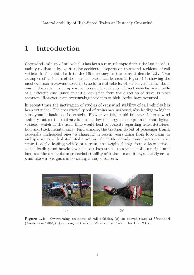
Crosswind stability of rail vehicles has been a research topic during the last decades,mainly motivated by overturning accidents. Reports on crosswind accidents of railvehicles in fact date back to the 19th century to the current decade [22]. Twoexamples of accidents of the current decade can be seen in Figure 1.1, showing themost common crosswind accident type for a rail vehicle, which is overturning aboutone of the rails. In comparison, crosswind accidents of road vehicles are mostlyof a different kind, since an initial deviation from the direction of travel is mostcommon. However, even overturning accidents of high lorries have occurred.
In recent times the motivation of studies of crosswind stability of rail vehicles hasbeen extended. The operational speed of trains has increased, also leading to higheraerodynamic loads on the vehicle. Heavier vehicles could improve the crosswindstability but on the contrary issues like lower energy consumption demand lightervehicles, which at the same time would lead to benefits regarding track deteriora-tion and track maintenance. Furthermore, the traction layout of passenger trains,especially high-speed ones, is changing in recent years going from loco-trains tomultiple units with distributed traction. Since the aerodynamic forces are mostcritical on the leading vehicle of a train, the weight change from a locomotive -as the leading and heaviest vehicle of a loco-train - to a vehicle of a multiple unitincreases the demands on crosswind stability of trains. In addition, unsteady cross-wind like various gusts is becoming a major concern.
(a) (b)
Figure 1.1: Overturning accidents of rail vehicles, (a) on curved track at Uttendorf(Austria) in 2002, (b) on tangent track at Wasserauen (Switzerland) in 2007.
1
1. Introduction
The rail infrastructure is also important to take into account. Vehicles on narrowgauge lines usually run at lower operational speeds but the overturning stability isless compared to a normal gauge vehicle. Also bridges and embankments involvehigher wind speeds due to the atmospheric boundary layer and the accelerated flowat the top of an embankment. In addition, tunnels can be an important factor sincethe wind speed at a tunnel exit can increase significantly from zero inside the tunnelto the actual wind speed in open field. Curveous railway lines can lead to largelateral suspension deflections of the vehicle in the curves, causing a deteriorationof crosswind stability.
Also, a rail vehicle can be subjected to other unsteady wind phenomena in everydayoperation, including gusts in open field, gust-like wind conditions due to changesin the housing density and vegetation near the track as well as by-passing vehicles.
Since crosswind stability represents a safety issue, detailed information about thebehaviour of the vehicle at crosswind is desirable. However, field tests using a railvehicle at overturning risk are not practicable due to safety and economic reasons.Therefore, simulations represent a necessary and important tool, but attention hasto be paid to the correctness of the simulations at large suspension deflections, sincea rail vehicle is a highly nonlinear system.
In the present thesis, the rail vehicle behaviour under large lateral influences fromcurves and track imperfections is studied by means of measurements and simulationsand with respect to overturning risk. In particular, the vehicle response to unsteadycrosswind during curve negotiation is investigated.
Chapter 2 gives an overview of lateral rail vehicle dynamics on tangent and curvedtrack, without influence of crosswind. Fundamentals of vehicle aerodynamics incombination with crosswind are presented in Chapter 3. Then Chapter 4 combinesthe two previous chapters dealing with rail vehicle dynamics and overturning riskof a vehicle at unsteady crosswind. A summary of the present work, in particularthe appended papers is given in Chapter 5. Finally, Chapter 6 draws conclusionson the work and proposes future work.
2
Lateral Stability of High-Speed Trains at Unsteady Crosswind
2 Lateral rail vehicle dynamics
2.1 Fundamentals
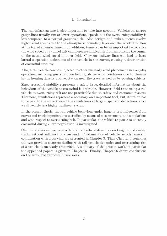
A rail vehicle often consists of a carbody supported by two running gears, and high-speed rail vehicles are designed as bogie vehicles. Figure 2.1 shows schematicallythe setup of a typical rail vehicle including the coordinate system of the carbodyand associated motion components.
Figure 2.1: Side and top views of a bogie rail vehicle. Longitudinal motion x, lateralmotion y, vertical motion z, roll motion ϕ, pitch motion χ and yaw motion ψ [2].
The vehicle consists of a carbody supported by the two bogies through the secondarysuspension. Each bogie consists of a frame and two wheelsets, connected by theprimary suspension. Both the primary and secondary suspensions include springand damper components. Examples are air springs, coil springs, rubber springs andhydraulic dampers. The type of components is dependent on the desired suspen-sion characteristics. Furthermore, the suspensions include bumpstops, delimitingthe suspension motions in vertical and lateral directions. The force transmissionin longitudinal direction is usually achieved by traction rods (not shown in Fig-ure 2.1). The secondary suspension is often also equipped with one anti-roll barper bogie, counteracting roll motion of the carbody (not shown). In Sections 2.2and 2.3, special emphasis is put on the lateral rail vehicle dynamics since lateralloadings and excitations are of concern in this thesis.
3
2. Lateral rail vehicle dynamics
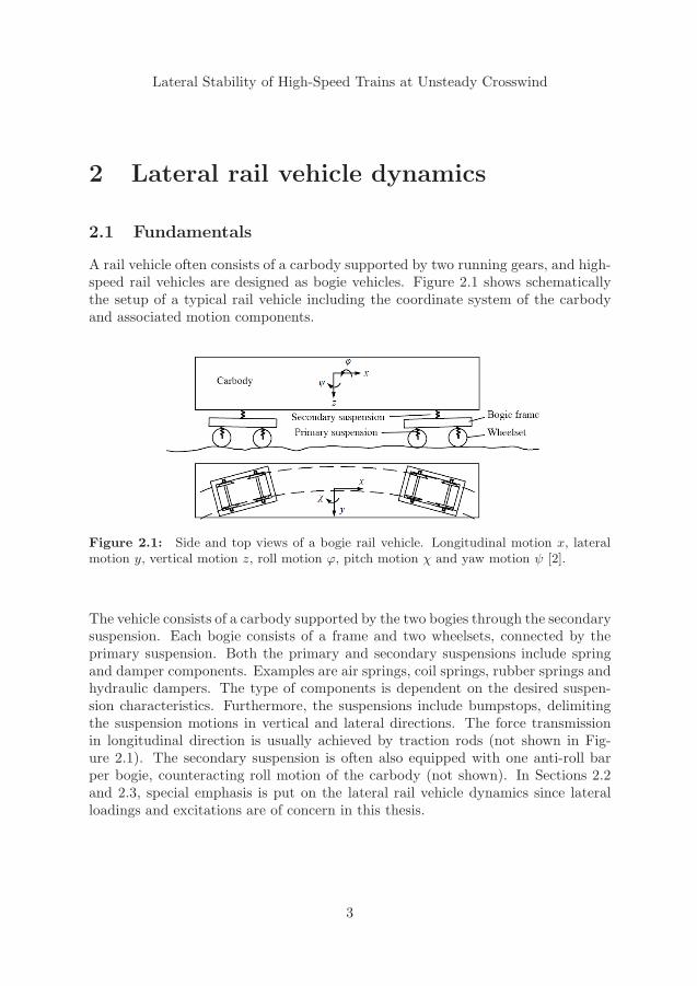
A vehicle running on a railway track is subjected to lateral influences due to trackirregularities. These irregularities represent deviations from the nominal track ge-ometry. They influence the motions of the vehicle due to excitations of the wheelsetsand have generally great impact on the wheel-rail forces and the ride comfort. Adefinition of different kinds of track irregularities is given by Figure 2.2. Lateral(line) and cant irregularities of long wavelength can cause low-frequency lateral androll motions on the carbody, which may lead to decreased crosswind stability [2].
Figure 2.2: Defintion of track irregularities [2].
2.2 Lateral dynamics on tangent track
On tangent (straight) track a vehicle is beside the track irregularities affected bylateral impacts due to the running behaviour of the vehicle itself. Vehicle ride in-stability can occur at high speed and in some cases this could also affect the vehicleability to withstand crosswind.
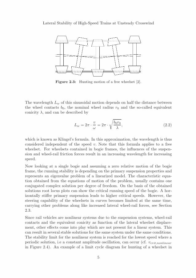
The running surface of a railway wheel has a conical shape and for wheelsets withtwo wheels on a common axle this often leads to a laterally self-stabilizing behaviourof the wheelsets when running along the tangent track. But by looking at the mid-dle of a free wheelset from above and following it along the track, one can recognizea sinusoidal lateral motion, see Figure 2.3. This phenomenon is called hunting andwas first described in [35]. Thus, assuming an initial lateral displacement y0 of thewheelset in the track, the lateral displacement y(t) of the wheelset centre of gravityrelative to the centre of the track can be expressed by
y(t) = y0 · sinωt. (2.1)
4
Lateral Stability of High-Speed Trains at Unsteady Crosswind
Figure 2.3: Hunting motion of a free wheelset [2].
The wavelength Lw of this sinusoidal motion depends on half the distance betweenthe wheel contacts b0, the nominal wheel radius r0 and the so-called equivalentconicity λ, and can be described by
Lw = 2π · vω
= 2π ·√b0r0λ, (2.2)
which is known as Klingel’s formula. In this approximation, the wavelength is thusconsidered independent of the speed v. Note that this formula applies to a freewheelset. For wheelsets contained in bogie frames, the influences of the suspen-sion and wheel-rail friction forces result in an increasing wavelength for increasingspeed.
Now looking at a single bogie and assuming a zero relative motion of the bogieframe, the running stability is depending on the primary suspension properties andrepresents an eigenvalue problem of a linearized model. The characteristic equa-tion obtained from the equations of motion of the problem, usually contains oneconjugated complex solution per degree of freedom. On the basis of the obtainedsolutions root locus plots can show the critical running speed of the bogie. A hor-izontally stiffer primary suspension leads to higher critical speeds. However, thesteering capability of the wheelsets in curves becomes limited at the same time,carrying other problems along like increased lateral wheel-rail forces, see Section2.3.
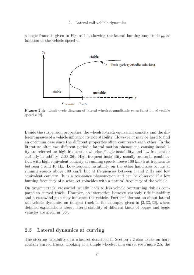
Since rail vehicles are nonlinear systems due to the suspension systems, wheel-railcontacts and the equivalent conicity as function of the lateral wheelset displace-ment, other effects come into play which are not present for a linear system. Thiscan result in several stable solutions for the same system under the same conditions.The stability limit for the nonlinear system is reached for the lowest speed where aperiodic solution, i.e a constant amplitude oscillation, can occur (cf. vcrit,nonlinearin Figure 2.4). An example of a limit cycle diagram for hunting of a wheelset in
5
2. Lateral rail vehicle dynamics
a bogie frame is given in Figure 2.4, showing the lateral hunting amplitude y0 asfunction of the vehicle speed v.
Figure 2.4: Limit cycle diagram of lateral wheelset amplitude y0 as function of vehiclespeed v [2].
Beside the suspension properties, the wheelset-track equivalent conicity and the dif-ferent masses of a vehicle influence its ride stability. However, it may be hard to findan optimum case since the different properties often counteract each other. In theliterature often two different periodic lateral motion phenomena causing instabil-ity are referred to: high-frequent or wheelset/bogie instability, and low-frequent orcarbody instability [2, 33, 36]. High-frequent instability usually occurs in combina-tion with high equivalent conicity at running speeds above 100 km/h at frequenciesbetween 4 and 10 Hz. Low-frequent instability on the other hand also occurs atrunning speeds above 100 km/h but at frequencies between 1 and 2 Hz and lowequivalent conicity. It is a resonance phenomenon and can be observed if a lowhunting frequency of a wheelset coincides with a natural frequency of the vehicle.
On tangent track, crosswind usually leads to less vehicle overturning risk as com-pared to curved track. However, an interaction between carbody ride instabilityand a crosswind gust may influence the vehicle. Further information about lateralrail vehicle dynamics on tangent track is, for example, given in [2, 33, 36], wheredetailed explanations about lateral stability of different kinds of bogies and bogievehicles are given in [36].
2.3 Lateral dynamics at curving
The steering capability of a wheelset described in Section 2.2 also exists on hori-zontally curved tracks. Looking at a simple wheelset in a curve, see Figure 2.5, the
6
Lateral Stability of High-Speed Trains at Unsteady Crosswind
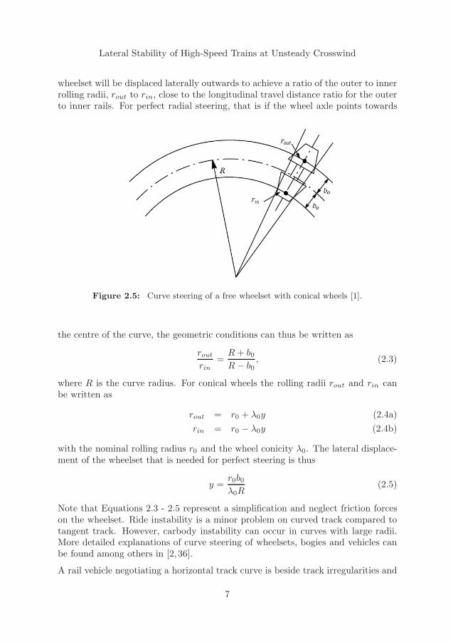
wheelset will be displaced laterally outwards to achieve a ratio of the outer to innerrolling radii, rout to rin, close to the longitudinal travel distance ratio for the outerto inner rails. For perfect radial steering, that is if the wheel axle points towards
Figure 2.5: Curve steering of a free wheelset with conical wheels [1].
the centre of the curve, the geometric conditions can thus be written as
routrin
= R+ b0R− b0 , (2.3)
where R is the curve radius. For conical wheels the rolling radii rout and rin canbe written as
rout = r0 + λ0y (2.4a)rin = r0 − λ0y (2.4b)
with the nominal rolling radius r0 and the wheel conicity λ0. The lateral displace-ment of the wheelset that is needed for perfect steering is thus
y = r0b0λ0R
(2.5)
Note that Equations 2.3 - 2.5 represent a simplification and neglect friction forceson the wheelset. Ride instability is a minor problem on curved track compared totangent track. However, carbody instability can occur in curves with large radii.More detailed explanations of curve steering of wheelsets, bogies and vehicles canbe found among others in [2, 36].
A rail vehicle negotiating a horizontal track curve is beside track irregularities and
7
2. Lateral rail vehicle dynamics
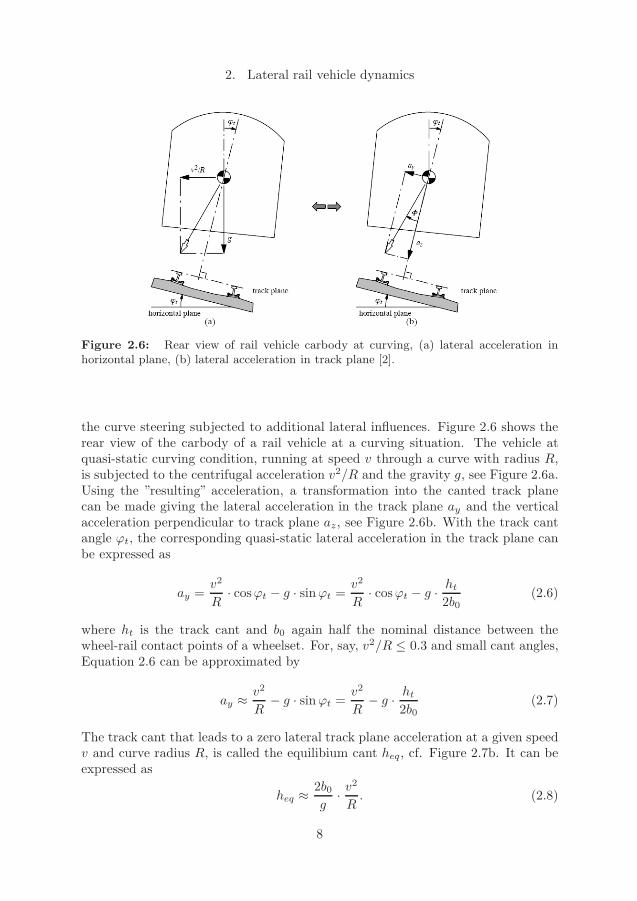
Figure 2.6: Rear view of rail vehicle carbody at curving, (a) lateral acceleration inhorizontal plane, (b) lateral acceleration in track plane [2].
the curve steering subjected to additional lateral influences. Figure 2.6 shows therear view of the carbody of a rail vehicle at a curving situation. The vehicle atquasi-static curving condition, running at speed v through a curve with radius R,is subjected to the centrifugal acceleration v2/R and the gravity g, see Figure 2.6a.Using the ”resulting” acceleration, a transformation into the canted track planecan be made giving the lateral acceleration in the track plane ay and the verticalacceleration perpendicular to track plane az, see Figure 2.6b. With the track cantangle ϕt, the corresponding quasi-static lateral acceleration in the track plane canbe expressed as
ay = v2
R· cosϕt − g · sinϕt = v
2
R· cosϕt − g · ht2b0
(2.6)
where ht is the track cant and b0 again half the nominal distance between thewheel-rail contact points of a wheelset. For, say, v2/R ≤ 0.3 and small cant angles,Equation 2.6 can be approximated by
ay ≈ v2
R− g · sinϕt = v
2
R− g · ht2b0
(2.7)
The track cant that leads to a zero lateral track plane acceleration at a given speedv and curve radius R, is called the equilibium cant heq, cf. Figure 2.7b. It can beexpressed as
heq ≈ 2b0g· v
2
R. (2.8)
8
Lateral Stability of High-Speed Trains at Unsteady Crosswind
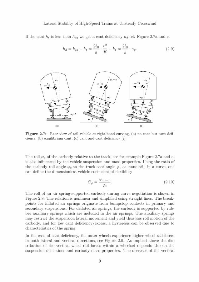
If the cant ht is less than heq we get a cant deficiency hd, cf. Figure 2.7a and c,
hd = heq − ht ≈ 2b0g· v
2
R− ht ≈ 2b0
g· ay. (2.9)
Figure 2.7: Rear view of rail vehicle at right-hand curving, (a) no cant but cant defi-ciency, (b) equilibrium cant, (c) cant and cant deficiency [2].
The roll ϕc of the carbody relative to the track, see for example Figure 2.7a and c,is also influenced by the vehicle suspension and mass properties. Using the ratio ofthe carbody roll angle ϕc to the track cant angle ϕt at stand-still in a curve, onecan define the dimensionless vehicle coefficient of flexibility
Cϕ = ϕc,v=0ϕt. (2.10)
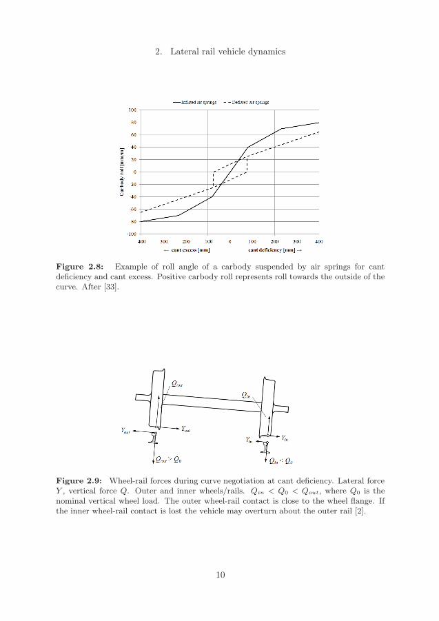
The roll of an air spring-supported carbody during curve negotiation is shown inFigure 2.8. The relation is nonlinear and simplified using straight lines. The break-points for inflated air springs originate from bumpstop contacts in primary andsecondary suspensions. For deflated air springs, the carbody is supported by rub-ber auxiliary springs which are included in the air springs. The auxiliary springsmay restrict the suspension lateral movement and yield thus less roll motion of thecarbody, and for low cant deficiency/excess, a hysteresis can be observed due tocharacteristics of the spring.
In the case of cant deficiency, the outer wheels experience higher wheel-rail forcesin both lateral and vertical directions, see Figure 2.9. As implied above the dis-tribution of the vertical wheel-rail forces within a wheelset depends also on thesuspension deflections and carbody mass properties. The decrease of the vertical
9
2. Lateral rail vehicle dynamics
Figure 2.8: Example of roll angle of a carbody suspended by air springs for cantdeficiency and cant excess. Positive carbody roll represents roll towards the outside of thecurve. After [33].
Figure 2.9: Wheel-rail forces during curve negotiation at cant deficiency. Lateral forceY , vertical force Q. Outer and inner wheels/rails. Qin < Q0 < Qout, where Q0 is thenominal vertical wheel load. The outer wheel-rail contact is close to the wheel flange. Ifthe inner wheel-rail contact is lost the vehicle may overturn about the outer rail [2].
10
Lateral Stability of High-Speed Trains at Unsteady Crosswind
wheel-rail force on the (inner) wheel/rail is often called wheel-unloading. The ap-pearance of crosswind can lead to even lower vertical wheel-rail forces, thus a higherwheel-unloading on the windward wheel/rail. Wheel-unloading can be used as acriterion for vehicle overturning, see Section 4.1.
The lateral track plane acceleration and thus the cant deficiency should be limiteddue to risk of ride discomfort and lateral track shift. A limit speed can be foundusing Equation 2.7, thus
vlim =√R(ay,lim + g ht2b0
) =√R(hd,lim + ht)
g
2b0. (2.11)
This speed may be further reduced due to strong crosswind.
2.4 Air springs and bumpstops
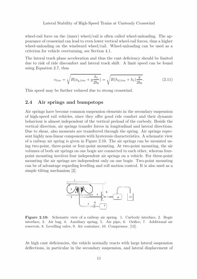
Air springs have become common suspension elements in the secondary suspensionof high-speed rail vehicles, since they offer good ride comfort and their dynamicbehaviour is almost independent of the vertical preload of the carbody. Beside thevertical direction, air springs transfer forces in longitudinal and lateral directions.Due to shear, also moments are transferred through the spring. Air springs repre-sent highly non-linear components with hysteresis characteristics. A schematic viewof a railway air spring is given in Figure 2.10. The air springs can be mounted us-ing two-point, three-point or four-point mounting. At two-point mounting, the airvolumes of both air springs on one bogie are connected to each other, whereas four-point mounting involves four independent air springs on a vehicle. For three-pointmounting the air springs are independent only on one bogie. Two-point mountingcan be of advantage regarding levelling and roll motion control. It is also used as asimple tilting mechanism [2].
Figure 2.10: Schematic view of a railway air spring. 1. Carbody interface, 2. Bogieinterface, 3. Air bag, 4. Auxiliary spring, 5. Air pipe, 6. Orifice, 7. Additional airreservoir, 8. Levelling valve, 9. Air container, 10. Compressor. [12].
At high cant deficiencies, the vehicle normally reacts with large lateral suspensiondeflections, in particular in the secondary suspension, and lateral displacement of
11
2. Lateral rail vehicle dynamics
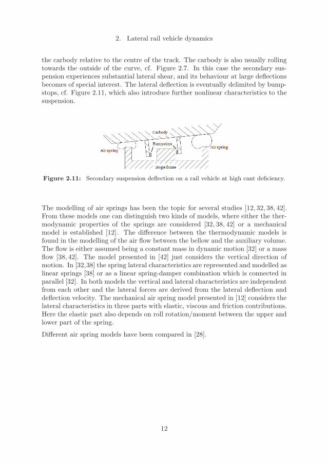
the carbody relative to the centre of the track. The carbody is also usually rollingtowards the outside of the curve, cf. Figure 2.7. In this case the secondary sus-pension experiences substantial lateral shear, and its behaviour at large deflectionsbecomes of special interest. The lateral deflection is eventually delimited by bump-stops, cf. Figure 2.11, which also introduce further nonlinear characteristics to thesuspension.
Figure 2.11: Secondary suspension deflection on a rail vehicle at high cant deficiency.
The modelling of air springs has been the topic for several studies [12, 32, 38, 42].From these models one can distinguish two kinds of models, where either the ther-modynamic properties of the springs are considered [32, 38, 42] or a mechanicalmodel is established [12]. The difference between the thermodynamic models isfound in the modelling of the air flow between the bellow and the auxiliary volume.The flow is either assumed being a constant mass in dynamic motion [32] or a massflow [38, 42]. The model presented in [42] just considers the vertical direction ofmotion. In [32,38] the spring lateral characteristics are represented and modelled aslinear springs [38] or as a linear spring-damper combination which is connected inparallel [32]. In both models the vertical and lateral characteristics are independentfrom each other and the lateral forces are derived from the lateral deflection anddeflection velocity. The mechanical air spring model presented in [12] considers thelateral characteristics in three parts with elastic, viscous and friction contributions.Here the elastic part also depends on roll rotation/moment between the upper andlower part of the spring.
Different air spring models have been compared in [28].
12
Lateral Stability of High-Speed Trains at Unsteady Crosswind
3 Vehicle aerodynamics and crosswind
3.1 Vehicle aerodynamics
When an object, e.g. a vehicle, is moving in a fluid, e.g. air, the vehicle interactswith the fluid due to its shape and surface. Assuming a control volume around thevehicle, the law of conversation of mass applies, and thus changes in the curvatureof the vehicle surface lead to local changes in the flow velocity and the flow pres-sure. For a non-viscous and incompressible flow the relation is given by Bernoulli’sequation,
p+ ρ2u2 = const, (3.1)
where p is the static pressure, ρ the fluid density and u the flow velocity along astreamline [11, 31, 44]. The term
ρ
2u2 = q (3.2)
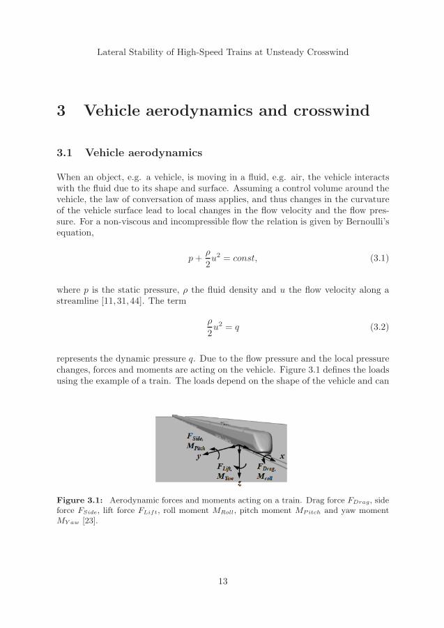
represents the dynamic pressure q. Due to the flow pressure and the local pressurechanges, forces and moments are acting on the vehicle. Figure 3.1 defines the loadsusing the example of a train. The loads depend on the shape of the vehicle and can
Figure 3.1: Aerodynamic forces and moments acting on a train. Drag force FDrag, sideforce FSide, lift force FLift, roll moment MRoll, pitch moment MPitch and yaw momentMY aw [23].
13
3. Vehicle aerodynamics and crosswind
be expressed as
FDrag = q ·At · CDrag (3.3a)FSide = q ·At · CSide (3.3b)FLift = q ·At · CLift (3.3c)MRoll = q ·At · lt · CRoll (3.3d)MPitch = q ·At · lt · CPitch (3.3e)MY aw = q ·At · lt · CY aw, (3.3f)
where At is a reference area, lt a reference length and C the aerodynamic coeffi-cients. Several reference areas and length dimensions are used depending on thevehicle. For rail vehicles in Europe, the standard EN 14067-1 applies [17]. Fortrains, the reference frame for the loads shown in Figure 3.1 is often located athalf the bogie distance between the two bogies of the first car and on top of raillevel [23]. For road vehicles, a reference frame located at half the axle distance afterthe first axle is often used [34].
The dimensionless aerodynamic coefficients C in Equations 3.3a - 3.3f are mainlydependent on the vehicle shape and give information about the aerodynamic char-acteristics of the vehicle regardless of its size or speed. The coefficients are obtainedby either wind tunnel experiments or Computational Fluid Dynamics (CFD). Inboth cases a vehicle model is standing still and the fluid flows against the model.However, CFD using moving vehicle models has been presented recently [37]. ForCFD there are four main modelling technologies available:
� Direct Numerical Simulations (DNS) resolve the governing Navier-Stokes equa-tions directly, why this method is very time consuming and mostly applied inresearch. Due to the required computational effort, DNS cannot be used forcrosswind calculations today.
� Large Eddy Simulations (LES) resolve the larger turbulence scales by thecomputational mesh. Smaller, energy dissipating scales, that are unresolved,have to be modelled. Concerning crosswind calculations of trains includinghigh Reynolds numbers, LES also need high computational effort, why LESare not used in industrial context.
� Detached Eddy Simulations (DES) represent a relatively new methodologyand is a mixture of LES and RANS [43]. It uses LES away from solid walls andapplies RANS close to walls. Both LES and DES are methods for unsteadyflow calculations [23].
� The methodology of Reynolds Average Navier Stokes (RANS) estimates theturbulent flow by a time average and variance of the flow fields, where for thetime average t → ∞ leads to time independent RANS. In addition, turbu-lence models have to be introduced. RANS often delivers feasible steady-state
14
Lateral Stability of High-Speed Trains at Unsteady Crosswind
solutions for engineering applications. If one separates the time scales for themean flow and the turbulence, one can instead of the time average t → ∞choose a sufficiently long integral time for the turbulence fluctuations to av-erage out. This approach is referred to as Unsteady Reynolds Average NavierStokes (URANS) [23].
An overview of computational methods in combination with crosswind stability ofrail vehicles is given in [22].
3.2 Crosswind
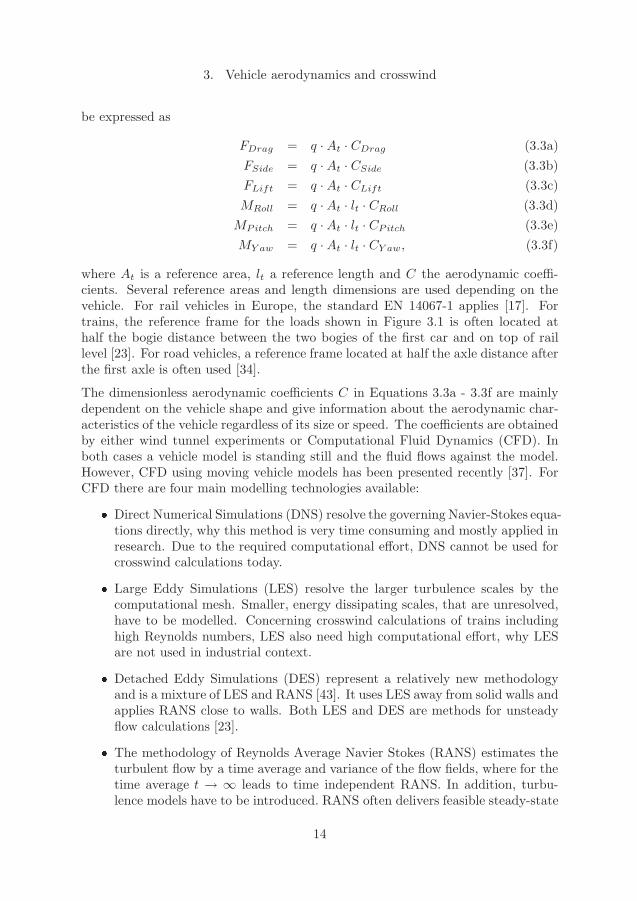
For road and rail vehicles in crosswind, the pressure distribution and thus theaerodynamic forces and moments are dependent on several variables that originatefrom the vehicle and the wind properties. These are the reference area At, thereference height h and the vehicle speed v (concerning the vehicle properties), theair density ρ and viscosity ν as well as the wind speed vw, the wind angle relativeto the vehicle travel direction β∗, the turbulence length scale and the standarddeviation of the wind speed (concerning the wind properties) [4, 23]. Figure 3.2shows the connection between the vehicle speed v, the wind speed vw including itsyaw angle relative to the track β∗, as well as the resultant wind speed vr and itsyaw angle β using the example of a train.
Figure 3.2: Wind situation and notation of velocity vectors for a train subjected tocrosswind. Top view [23].
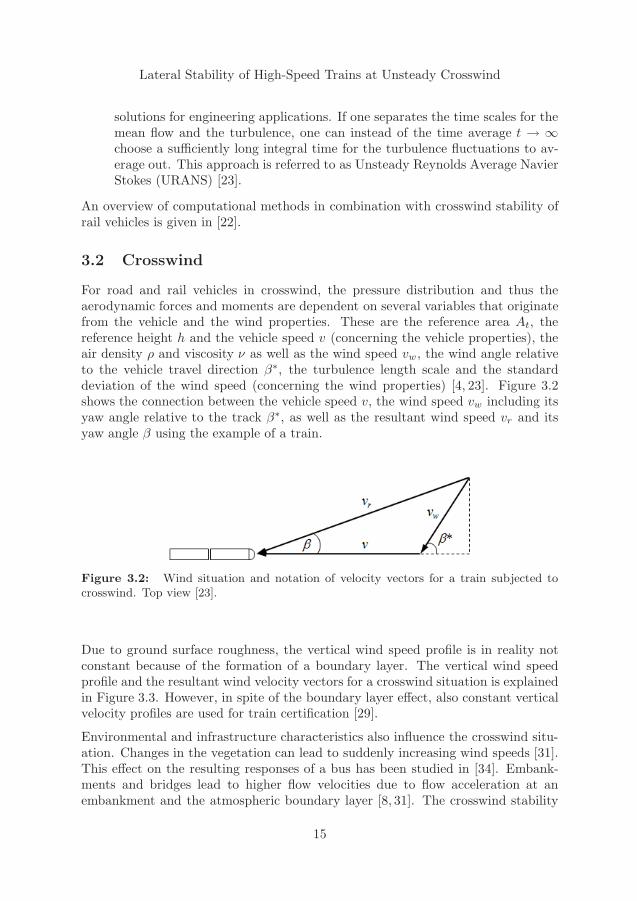
Due to ground surface roughness, the vertical wind speed profile is in reality notconstant because of the formation of a boundary layer. The vertical wind speedprofile and the resultant wind velocity vectors for a crosswind situation is explainedin Figure 3.3. However, in spite of the boundary layer effect, also constant verticalvelocity profiles are used for train certification [29].
Environmental and infrastructure characteristics also influence the crosswind situ-ation. Changes in the vegetation can lead to suddenly increasing wind speeds [31].This effect on the resulting responses of a bus has been studied in [34]. Embank-ments and bridges lead to higher flow velocities due to flow acceleration at anembankment and the atmospheric boundary layer [8, 31]. The crosswind stability
15
3. Vehicle aerodynamics and crosswind
Figure 3.3: Wind velocity profile and resultant wind velocity vectors for a moving carin crosswind [11].
of a (high-speed) train on an embankment was investigated in [26, 45].
Due to the atmospheric boundary layer and the resulting wind speed, wind tunneltests for crosswind situations should be made using a moving model [4], performed,for example, like in [7, 15, 19]. However, also open field measurements of aerody-namic loads were performed and compared to wind tunnel tests by [10], resulting ingood agreement, but showing a discrepancy for the lift coefficient caused by localroughness effects in the wind tunnel tests. A review on ground vehicles in crosswindis given in [4–6], considering both steady and unsteady aerodynamic loads as wellas the interaction of the aerodynamic loads and the vehicle suspension system. Arecent state-of-the-art review on crosswind stability, mainly from aerodyamics pointof view, is given in [9].
Gust modelling
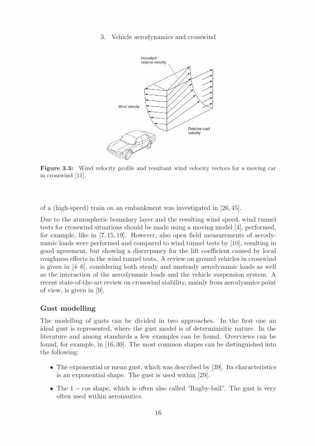
The modelling of gusts can be divided in two approaches. In the first one anideal gust is represented, where the gust model is of determinisitic nature. In theliterature and among standards a few examples can be found. Overviews can befound, for example, in [16,30]. The most common shapes can be distinguished intothe following:
� The exponential or mean gust, which was described by [39]. Its characteristicsis an exponential shape. The gust is used within [29].
� The 1 − cos shape, which is often also called ”Rugby-ball”. The gust is veryoften used within aeronautics.
16
Lateral Stability of High-Speed Trains at Unsteady Crosswind
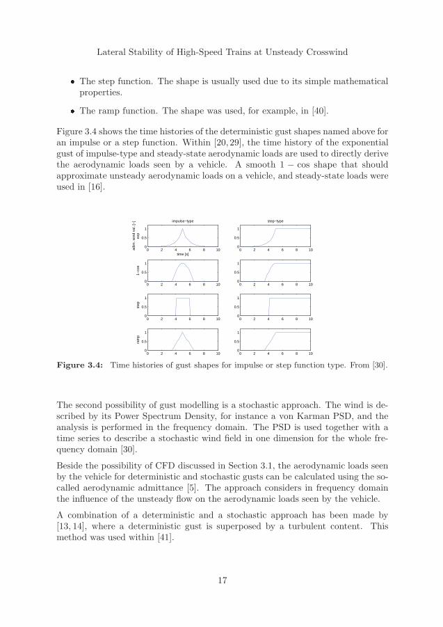
� The step function. The shape is usually used due to its simple mathematicalproperties.
� The ramp function. The shape was used, for example, in [40].
Figure 3.4 shows the time histories of the deterministic gust shapes named above foran impulse or a step function. Within [20, 29], the time history of the exponentialgust of impulse-type and steady-state aerodynamic loads are used to directly derivethe aerodynamic loads seen by a vehicle. A smooth 1 − cos shape that shouldapproximate unsteady aerodynamic loads on a vehicle, and steady-state loads wereused in [16].
0 2 4 6 8 100
0.5
1
time [s]
adim
. win
d va
l. [−
]ex
p
impulse−type
0 2 4 6 8 100
0.5
1
step−type
0 2 4 6 8 100
0.5
1
1−co
s
0 2 4 6 8 100
0.5
1
0 2 4 6 8 100
0.5
1
step
0 2 4 6 8 100
0.5
1
0 2 4 6 8 100
0.5
1
ram
p
0 2 4 6 8 100
0.5
1
Figure 3.4: Time histories of gust shapes for impulse or step function type. From [30].
The second possibility of gust modelling is a stochastic approach. The wind is de-scribed by its Power Spectrum Density, for instance a von Karman PSD, and theanalysis is performed in the frequency domain. The PSD is used together with atime series to describe a stochastic wind field in one dimension for the whole fre-quency domain [30].
Beside the possibility of CFD discussed in Section 3.1, the aerodynamic loads seenby the vehicle for deterministic and stochastic gusts can be calculated using the so-called aerodynamic admittance [5]. The approach considers in frequency domainthe influence of the unsteady flow on the aerodynamic loads seen by the vehicle.
A combination of a deterministic and a stochastic approach has been made by[13, 14], where a deterministic gust is superposed by a turbulent content. Thismethod was used within [41].
17

Lateral Stability of High-Speed Trains at Unsteady Crosswind
4 Rail vehicle dynamics and overturning
risk at unsteady crosswind
The failure of rail vehicles subjected to crosswind mostly occurs in terms of vehicleoverturning about one of the rails, primarily about the outer rails in curves, cf.Figure 2.9 [2].
4.1 Overturning risk
Several methods and criteria exist to describe the overturning of a rail vehicle,at steady or unsteady crosswind, and have been used in various studies and instandards. Four methods are described here to give a short overview, withoutclaiming completeness.
Wheel unloading
The wheel unloading (Q0−Q)/Q0, cf. Figure 2.9, is an accepted quantity to predictthe overturning risk of a rail vehicle. This method is used in several studies, forexample [16, 48, 49], as well as national and international standards [20, 29]. Thewheel unloading is evaluated for the windward wheels and may not exceed a certainpercentage of the static force. This percentage is often set to 90%, thus
Q0 −QQ0
≤ 0.9. (4.1)
The quotient is often low-pass filtered with 2 Hz or 1.5 Hz [20,29,40], motivated bythe low-frequency nature of the overturning process, and thus mainly neglecting theinfluence of the track irregularities. The choice of a rather low cut-off frequency ofthe filtering can be discussed though. Still there are also standards that completelyneglect the effects of track irregularities [29].
It is also possible to take a whole bogie into account by calculating the meanunloading value for the inner wheels of the wheelsets of one bogie [20, 29]. Thewheel unloading method can be used both in field measurements and simulations.
Moment method
The moment method calculates moments about the leeward/outer rail. The methodrequires the aerodynamic loads on the vehicle and compares the stabilizing momentdue to the gravity forces of the vehicle with the overturning moment due to the
19
4. Rail vehicle dynamics and overturning risk at unsteady crosswind
aerodynamic and centrifugal loads. If these moments are equal, the vehicle starts tooverturn. Usually the method does not take dynamic effects from track irregularitiesinto account. However, Andersson et al. [2] describe a moment method consideringdynamic lateral track input. Due to the input requirement of aerodynamic loads,this method can be applied for simulations only.
Intercept method
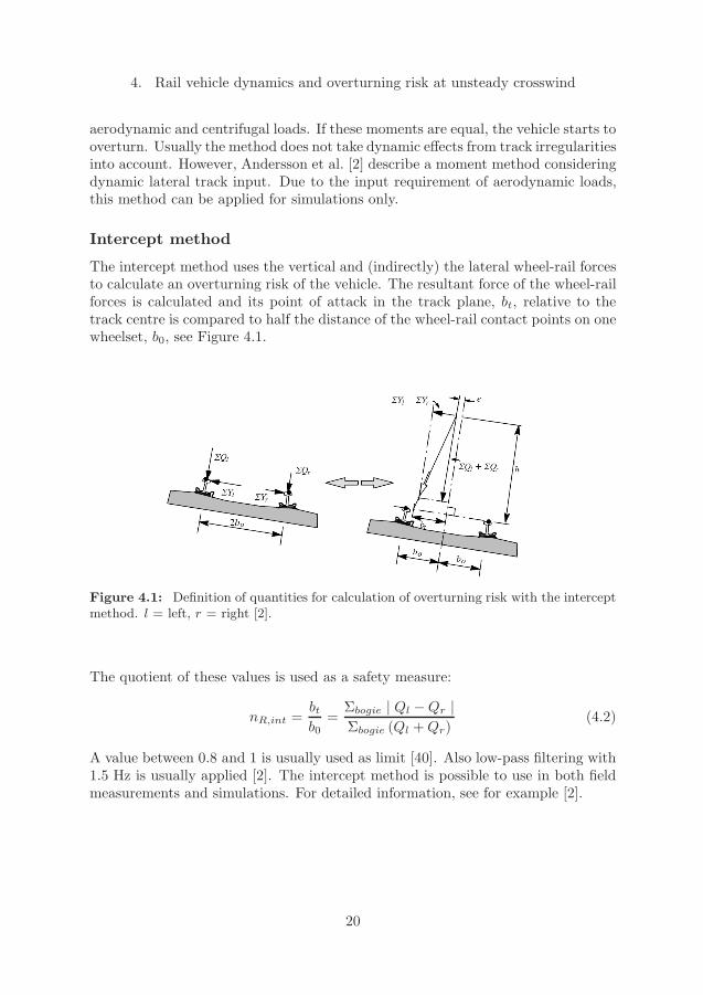
The intercept method uses the vertical and (indirectly) the lateral wheel-rail forcesto calculate an overturning risk of the vehicle. The resultant force of the wheel-railforces is calculated and its point of attack in the track plane, bt, relative to thetrack centre is compared to half the distance of the wheel-rail contact points on onewheelset, b0, see Figure 4.1.
Figure 4.1: Definition of quantities for calculation of overturning risk with the interceptmethod. l = left, r = right [2].
The quotient of these values is used as a safety measure:
nR,int = btb0
= Σbogie | Ql −Qr |Σbogie (Ql +Qr)
(4.2)
A value between 0.8 and 1 is usually used as limit [40]. Also low-pass filtering with1.5 Hz is usually applied [2]. The intercept method is possible to use in both fieldmeasurements and simulations. For detailed information, see for example [2].
20
Lateral Stability of High-Speed Trains at Unsteady Crosswind
Simulation of real overturning
Another possibility to assess overturning risk is to simulate a vehicle that actuallyis overturning. Then the simulation model must be able to handle loss of wheel-rail contact, usually at the inner rail in curves, and large vehicle motions at theoverturning.
4.2 Modelling and simulation of crosswind stability
The modelling and simulation of crosswind stability from a rail vehicle dynamicspoint of view has been a research topic in some studies, mostly leading to a riskassessment, for example [3, 16], and also some standards take the rail vehicle dy-namics into account [18, 20, 29].
Usually the crosswind stability of a rail vehicle is investigated by applying aerody-namic loads on a vehicle model within dynamic multibody simulations. However,also simpler approaches using quasi-static models have been used [25]. Concerningthe aerodynamic loads, it can be distinguished between just temporal gusts andspatio-temporal gusts. The former considers aerodynamic coefficients obtained bywind-tunnel tests or steady-state CFD in combination with a time series of a deter-ministic gust shape. This is used in [20,29]. A spatio-temporal gust includes effectsof varying aerodynamic loads in space and also in time due the moving vehicle.
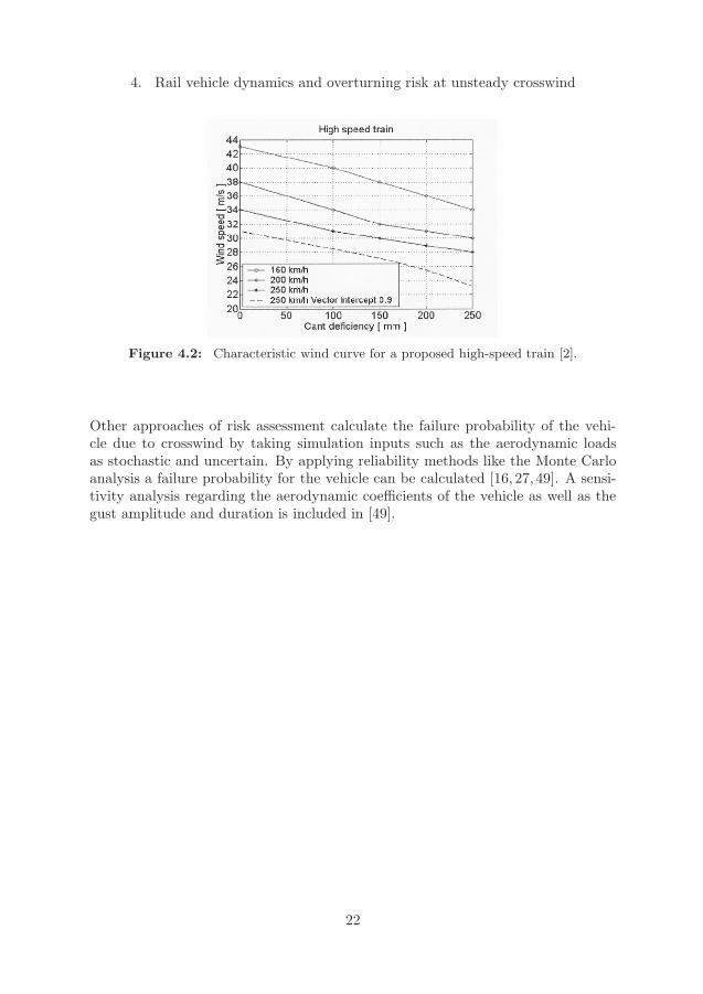
The wind scenarios used for the multibody simulations can represent either de-terministic gust models or measured transient wind loads. Several deterministicgusts have been proposed, either with a meteorological background or as simplerapproaches to study vehicle reactions, see for example [16, 21, 24, 29, 40, 47]. A de-terministic gust in combination with superposed turbulent fluctuations has beenused by [41, 49]. In recent time unsteady CFD have been used to obtain aerody-namic loads on a vehicle from gusts, cf. Chapter 3. Examples are [24, 37]. Theresults from [24] have been used in [47] to study the reponse of a high-speed railvehicle to unsteady crosswind, including a comparison of a spatio-temporal and ajust temporal gust using the TSI gust shape.For a risk assessment the simulation results are often shown as Characteristic WindCurves (CWC) of the vehicle, showing, for example, the critical wind speed for arail vehicle for different cant deficiencies and vehicle speeds, cf. Figure 4.2. The riskevaluation is then made by comparing the results to predefined conditions. Exam-ples of such conditions found in the literature are a number of possible overturningaccidents on a certain track segment [3], or a comparison to other vehicles that areknown to be safe [20, 29, 46].
21
4. Rail vehicle dynamics and overturning risk at unsteady crosswind
Figure 4.2: Characteristic wind curve for a proposed high-speed train [2].
Other approaches of risk assessment calculate the failure probability of the vehi-cle due to crosswind by taking simulation inputs such as the aerodynamic loadsas stochastic and uncertain. By applying reliability methods like the Monte Carloanalysis a failure probability for the vehicle can be calculated [16, 27, 49]. A sensi-tivity analysis regarding the aerodynamic coefficients of the vehicle as well as thegust amplitude and duration is included in [49].
22
Lateral Stability of High-Speed Trains at Unsteady Crosswind
5 The present work
Rail vehicles can thus experience strong lateral influences during everyday opera-tion caused by curve negotiation, track imperfections and crosswind. This normallyresults in large suspension deflections and carbody displacements, which makes thevehicle even more sensitive to crosswind. Concerning crosswind stability, simula-tions for the prediction of a possible overturning risk are desirable, but this requiresknowledge of the lateral vehicle dynamics at large suspension deflections, in par-ticular in the secondary suspension. The modelling of the latter is important toachieve feasible simulation results at large shear in the suspension. If the simula-tions yield reasonable results, they represent an important tool for the predictionof vehicle overturning.
The present work investigates the lateral dynamics of a high-speed rail vehicle dueto large lateral influences and at large suspension deflections by means of multibodysimulations validated by field measurements. Multibody simulations are then usedto study the vehicle response to unsteady crosswind. The work is described in twoappended papers, but also summerized below.
5.1 Summary of Paper A
Paper A presents field measurements and multibody simulations of the lateral dy-namics of a high-speed rail vehicle at large secondary suspension deflections dueto track curves and track irregularities. In this way curve negotiation at differentcant deficiencies were studied. The simulations were performed using a half-vehiclemodel in 2D and a model of a whole vehicle in 3D, both models containing differentmodels of the secondary air spring suspension. The simulations showed good agree-ment with the measurements concerning relative carbody-bogie lateral displacementevaluated at a level of about 0.5 m above top of rail. At high levels of cant defi-ciency, the relative roll angle between carbody and bogie frame was overestimatedby the simulations due to levelling effects of the air springs. The lack of frictionin the air spring model of the 2D-model resulted in higher relative displacementscompared to the 3D-model. The 3D simulation results were also compared to anunsteady crosswind case with respect to overturning risk by means of the wheelunloading measure.
23
5. The present work
5.2 Summary of Paper B
The response of a high-speed vehicle to unsteady crosswind during curve negotia-tion is studied in Paper B. Using multibody simulations, three different gusts areapplied to a vehicle model. The gusts are of deterministic kind and consist of a self-created simple artificial gust, the so-called Chinese hat prescribed in the TechnicalSpecification for Interoperability (TSI) [29], and a crosswind case at a tunnel exit.The aerodynamic loads are obtained from unsteady DES and the so-called QTGMapproach, resulting in spatio-temporal gusts that include aerodynamic effects inspace and time due to the varying flow along the track and the moving vehicle.The simple artificial gust is used to perform studies on the vehicle response due todifferent gust properties as well as for parameter variations on suspension and massproperties of the vehicle.
The vehicle showed strong lateral and roll reactions to the different gusts, and aninfluence of the gust duration and the relative difference between mean wind speedand maximum wind speed was observed. A variation of the ramp distance of thesimple artificial gust led to higher wheel-unloading for shorter ramp distances. Theleading bogie showed in general higher wheel-unloading, independent of the calcu-lation method of the aerodynamic loads. For the trailing bogie, the loads obtainedby the QTGM approach yielded higher wheel-unloading than the DES loads. Acomparison of a spatio-temporal and a temporal TSI gust did not show signifi-cant differences in the vehicle response in terms of the maximum wheel unloading.However, the carbody showed higher roll motion oscillations due to the temporalgust. Concerning the variation of suspension and mass properties of the vehicle,it was shown that the vertical location of the centre of gravity of the carbody andthe lateral bumpstop clearance significantly influence the crosswind stability of thevehicle.
24
Lateral Stability of High-Speed Trains at Unsteady Crosswind
6 Conclusions and future work
The purpose of this study was to investigate the response and lateral stability of ahigh-speed rail vehicle due to large lateral influences from track irregularities, trackcurves and unsteady crosswind. The work included studies (Paper A) of high-speed vehicle dynamics at large suspension deflections due to large lateral impactfrom track curves and track irregularities only, in order to analyse the reliabilityof multibody simulations at such conditions and with respect to overturning riskof the vehicle. The multibody simulations were performed in 2D and 3D, usingdifferent suspension models, and validated by field measurements.
It could be shown that the multibody simulations estimated the relative motions inthe secondary suspension well. The multibody simulations showed good agreementwith the field measurements in carbody-bogie lateral displacements, whereas therelative roll motion of the carbody was overestimated by the simulations at largersuspension deflections and thus cant deficiencies due to levelling effects of the airsprings. The lack of friction in the 2D air spring model resulted in higher displace-ments.
Furthermore, the response of a high-speed rail vehicle subjected to unsteady cross-wind during curve negotiation was investigated (Paper B). This contained the expo-sure of the vehicle to unsteady aerodynamic loads obtained from unsteady DES andQTGM. The deterministic gusts applied represented gusts in open field, includingthe so-called Chinese hat of the TSI, and a tunnel exit. Using a simple artificialgust, comparisons of different gust and curve timing and parameter studies on theinfluence of mass and suspension properties of the vehicle on crosswind sensitivitywere performed. It was shown that the vertical location of the centre of mass of thecarbody and the lateral bumpstop clearance influences the crosswind stability sig-nificantly. The QTGM approach was evaluated in terms of usage within rail vehicledynamics, leading to higher wheel unloading compared to DES loads, but offering afast approach for the application of unsteady aerodynamic loads. A comparison ofa spatio-temporal and a temporal TSI gust did not show significant differences inthe vehicle response. However, further investigations on this topic should be partof future work.
Possible future work can be suggested from both parts of the work. Concerning themodelling effects at large suspension deflections, additional effects concerning airsprings could be introduced. This includes the levelling mechanism of the springsas well as possible pneumatic connections of the air springs. Also other existing airspring models could be validated on a vehicle at large suspension deflections.
25
6. Conclusions and future work
Regarding the vehicle response to unsteady crosswind, further comparisons of tran-sient aerodynamic loads and just temporal or steady state loads could further showthe relevance of unsteady approaches. Also, more parameter studies on the vehicleproperties could highlight additional possibilities of counteractions to crosswind ef-fects.
In general, the influence of the track irregularities and the applied low-pass filteringwithin the different overturning criteria would be of interest for further investiga-tions.
26
Lateral Stability of High-Speed Trains at Unsteady Crosswind
References
[1] Andersson E and Berg M: Railway Systems and Rail Vehicles (in Swedish:Spartrafiksystem och sparfordon), Textbook, ISBN 978-91-7178-743-9, Dep. ofAeronautical and Vehicle Engineering, Royal Institute of Technology (KTH),Stockholm, Sweden, 2007.
[2] Andersson E, Berg M and Stichel S: Rail Vehicle Dynamics, Textbook, ISBN978-91-7415-272-2, Dep. of Aeronautical and Vehicle Engineering, Royal In-stitute of Technology (KTH), Stockholm, Sweden, 2007.
[3] Andersson E, Haggstrom J, Sima M and Stichel S: Assessment of train over-turning risk due to strong cross-winds, Proc. Instn. Mech. Engrs., Part F: JRail and Rapid Transit 218 F3, pp 213–223, 2004.
[4] Baker C J: Ground vehicles in high cross winds - Part I: Steady aerodynamicforces, J Fluids and Structures 5, pp 69 – 90, 1991.
[5] Baker C J: Ground vehicles in high cross winds - Part II: Unsteady aerody-namic forces, J Fluids and Structures 5, pp 91 – 111, 1991.
[6] Baker C J: Ground vehicles in high cross winds - Part III: The interactionof aerodynamic forces and the vehicle system, J Fluids and Structures 5, pp221 – 241, 1991.
[7] Baker C J: Train aerodynamic forces and moments from moving modelexperiments, J Wind Engineering Ind. Aerodynamics 24, pp 227 – 251, 1986.
[8] Baker C J: The determination of topographical exposure factors for railwayembankments, J Wind Engineering Ind. Aerodynamics 21, pp 89 – 99, 1985.
[9] Baker C, Cheli F, Orellano A, Paradot N, Proppe C and Rocchi D: Cross-wind effects on road and rail vehicles, Vehicle System Dynamics 47 No. 8, pp983 – 1022, 2009.
[10] Baker C J, Jones J, Lopez-Calleja F and Munday J: Measurements of thecross wind forces on trains, J Wind Engineering Ind. Aerodynamics 92, pp547 – 563, 2004.
[11] Barnard R H: Road Vehicle Aerodynamic Design - An Introduction, Textbook,ISBN 0-9540734-0-1, Mechaero Publishing, St Albans, England, 2001.
27
References
[12] Berg M: A three-dimensional airspring model with friction and orifice damp-ing, presented at 16th International Symposium on Dynamics of Vehicles onRoads and Tracks (IAVSD’99), Pretoria, South Africa, 30 August - 3 Septem-ber 1999. Vehicle System Dynamics 33 Supplement, pp 528–539, 2000.
[13] Bierbooms W and Cheng P-W: Stochastic gust model for design of calculationsof wind turbines, J Wind Engineering Ind. Aerodynamics 90, pp 1237 – 1251,2002.
[14] Bierbooms W: Constrained stochastic simulation-generation of time seriesaround some specific event in a normal process, Extremes 8, pp 207 – 224,2006.
[15] Bocciolone M, Cheli F, Corradi R, Muggiasca S and Tomasini G: Crosswindaction on rail vehicles: Wind tunnel experimental analyses, J Wind Engi-neerng Ind. Aerodynamics 96, pp 584 – 610, 2008.
[16] Carrarini A: Reliability based analysis of the crosswind stability of railwayvehicles, Ph.D. thesis, Technische Universitat Berlin, ISBN 3-8322-5232-0,Shaker Verlag, Aachen, Germany, 2006.
[17] CEN: EN 14067-1 - Railway Applications - Aerodynamics - Part 1: Symbolsand Units, European Norm, CEN/TC 256, 2003.
[18] CEN: prEN 14067-6 - Railway applications - Aerodynamics - Part 6: Re-quirements and test procedures for cross wind assessment, European Norm,CEN/TC 256, 2008.
[19] Cooper R K: The effect of cross-wind on trains, J Fluids Engineering 103, pp170 – 178, 1981.
[20] DB Netz AG: Ausgewahlte Maßnahmen und Anforderungen an das Gesamt-system Fahrweg/Fahrzeug - Aerodynamik/Seitenwind, RIL 80704, 2006.
[21] DEUFRAKO: Common DEUFRAKO Research on Cross Wind Effects onHigh Speed Railway Operation 2001 – 2004, Technical Report, 2005.
[22] Diedrichs B: Computational Methods for Crosswind Stability of RailwayTrains - A Literature Survey, TRITA-AVE Report 2005:27, ISSN 1651-7660,Dep. of Aeronautical and Vehicle Engineering, Royal Institute of Technology(KTH), Stockholm, Sweden, 2005.
[23] Diedrichs B: Studies of Two Aerodynamic Effects on High-Speed Trains:Crosswind Stability and Discomforting Car Body Vibrations Inside Tunnels,PhD Thesis, TRITA-AVE Report 2006:81, ISSN 1651-7660, Dep. of Aeronau-tical and Vehicle Engineering, Royal Institute of Technology (KTH), Stock-holm, Sweden, 2006.
28
Lateral Stability of High-Speed Trains at Unsteady Crosswind
[24] Diedrichs B: Unsteady aerodynamic crosswind stability of a high-speed trainsubjected to gusts of various rates, EUROMECH Colloquium 509 VehicleAerodynamics - External aerodynamics of railway vehicles, trucks, buses andcars, Berlin, Germany, 24-25 March, 2009.
[25] Diedrichs B, Ekequist M, Stichel S and Tengstrand H: Quasi-static modellingof wheel-rail reactions due to crosswind effects for various types of high-speedrolling stock, Proc. Instn. Mech. Engrs., Part F: J Rail and Rapid Transit 218F2, pp 133–148, 2004.
[26] Diedrichs B, Sima M, Orellano A and Tengstrand H: Crosswind stability of ahigh-speed train on a high embankment, Proc. Instn. Mech. Engrs., Part F: JRail and Rapid Transit 221 F2, pp 205 – 225, 2007.
[27] Ding Y, Sterling M and Baker C: An alternative approach to modelling trainstability in high cross winds, Proc. Instn. Mech. Engrs., Part F: J Rail andRapid Transit 22 F2, pp 85 – 97, 2008.
[28] Docquier N, Fisette P and Jeanmart H: Multiphysic modelling of railwayvehicles equipped with pneumatic suspension, Vehicle System Dynamics 45No. 6, pp 505 – 524, 2007.
[29] European Rail Agency: Technical Specification for Interoperability (TSI) -Rolling stock subsystem, 96/48/EC, 2008.
[30] Favre T and Thomas D: Transient Crosswind Stability of Vehicles - ALiterature Survey, TRITA-AVE Report 2007:60, ISSN 1651-7660, Dep. ofAeronautical and Vehicle Engineering, Royal Institute of Technology (KTH),Stockholm, Sweden, 2007.
[31] Hucho W-H (ed.): Aerodynamics of Road Vehicles - Fourth Edition, Text-book, ISBN 0-7680-0029-7, SAE International, 1998.
[32] Intec GmbH: SIMPACK Reference Guide - SIMPACK Release 8.9, 2008, soft-ware available at http://www.simpack.de.
[33] Iwnicki S (ed.): Handbook of Railway Vehicle Dynamics, Textbook, ISBN978-0-8493-3321-7, CRC Press, Taylor & Francis, Boca Raton, USA, 2006.
[34] Juhlin M: Assessment of Crosswind Performance of Buses, PhD Thesis,TRITA-AVE Report 2009:25, ISBN 978-91-7415-316-3, ISSN 1651-7660, Dep.of Aeronautical and Vehicle Engineering, Royal Institute of Technology(KTH), Stockholm, Sweden, 2009.
[35] Klingel J: Uber den Lauf von Eisenbahnwagen auf gerader Bahn, Organ furdie Fortschritte des Eisenbahnwesens, Neue Folge 20, pp 113–123, Tafel XXI,1883.
29
References
[36] Knothe K and Stichel S: Schienenfahrzeugdynamik, Textbook, ISBN 3-540-43429-1, Springer, Berlin, Germany, 2003.
[37] Krajnovic S and Bjerklund E: Simulation of the flow around high-speed trainsmeeting each other at the exit of a tunnel, presented at 21st InternationalSymposium on Dynamics of Vehicles on Roads and Tracks (IAVSD’09), Stock-holm, Sweden, 17-21 August, 2009.
[38] Krettek O and Grajnert J: Die Modelldarstellung pneumatischerFahrzeugfederungen und die Vorauswahl der Modellparameter, ZEV +DET Glas. Ann. 115 Nr. 5, pp 142–153, 1991.
[39] Larsen G C, Bierbooms W and Hansen K S: Statistics of local extremes, Tech-nical Report Risø-R-1220(EN), RisøNational Laboratory, Roskilde, Denmark,2003.
[40] Lippert S: On Side Wind Stability of Trains, TRITA-FKT Report 1999:38,ISSN 1103-470X, Dep. of Vehicle Engineering, Royal Institute of Technology(KTH), Stockholm, Sweden, 1999.
[41] Proppe C and Wetzel C: A probabilistic approach for assessing the crosswindstability of ground vehicles, presented at 21st International Symposium onDynamics of Vehicles on Roads and Tracks (IAVSD’09), Stockholm, Sweden,17-21 August, 2009.
[42] Quaglia G and Sorli M: Air Suspension Dimensionless Analysis and DesignProcedure, Vehicle System Dynamics 35 No. 6, pp 443–475, 2001.
[43] Spalart P R, Jou W-H, Strelets M and Allmaras S R: Comments on thefeasibility of LES for wings, and on a hybrid RANS/LES approach, Advancesin DNS/LES, 1st AFOSR Int. Conf on DNS/LES, Ruston LA. 4-8 August,1997.
[44] Spurk J H: Stromungslehre - Einfuhrung in die Theorie der Stromungen,Textbook, 4th edition, ISBN 3-540-61308-0, Springer, Berlin, Heidelberg, Ger-many, 1996.
[45] Suzuki M, Tanemoto K and Maeda T: Aerodynamic characteristics oftrain/vehicles under cross winds, J Wind Engineering Ind. Aerodynamics 91,pp 209 – 218, 2003.
[46] Thielkes T, Rud N, Heine C, Moller M and Driller J: Sicherheit des Eisenbahn-verkehrs bei Seitenwind - Fahrzeugseitige Anforderungen der neuen Richtlinie80704 der DB Netz AG, ZEVrail 132, pp 162–169, 2009.
[47] Thomas D, Diedrichs B, Berg M and Stichel S: Dynamics of a high-speed railvehicle negotiating curves at unsteady crosswind, presented at 21st Interna-tional Symposium on Dynamics of Vehicles on Roads and Tracks (IAVSD’09),Stockholm, Sweden, 17-21 August, 2009.
30
Lateral Stability of High-Speed Trains at Unsteady Crosswind
[48] Wetzel C and Proppe C: On the crosswind stability of high speed railwayvehicles, Proc. Appl. Math. Mech. 6 (2006), pp 341–342.
[49] Wetzel C and Proppe C: On reliability and sensitivity methods for vehiclesystems under stochastic crosswind-loads, to appear in Vehicle System Dy-namics.
31