ks / sks vertical split coupled inline pumps - taco - hvac · for a closed hydronic system under...
TRANSCRIPT
©Taco Catalog #300-1.3 Effective Date: 08/20/15Supersedes: 02/23/10 Printed in USA
(See Back Page for details)
NOW AVAILABLE WITH:
Taco Vertical Split Coupled inline pumps set a new standard in service and maintenance.Now available with SelfSensing Series with ProBalance®.
KS / SKS Vertical Split Coupled Inline Pumps
Water CirculationPumps & Circulators
Quiet, dependable power.Proven performance.Taco’s line of vertical split coupled inline pumps are designed for optimum performance and ease of installation and maintenance. They’re ideal for HVAC and industrial applications,including pressure boosting, cooling towers, and domestic water service flows to 12,000 GPM. For quick and easy repair, the split coupler design permits changing of the seal without disturbing the motor or piping. The axial load is hydraulically balanced to increase bearing life and deliver better pump efficiencies and lower NPSH requirements. The recirculating line flushes seal faces and extends seal life, resulting in less pump downtime due to seal leaks. Optimum pump efficiency is achieved by close running impeller to casing clearances.
Other important features include:Motor Drive is isolated from the system with the split coupler design.
Precision aluminum coupling.
High efficiency impellers standard on all sizes.Standard drilled and tapped mounting holesat base of casing.
A seal flush line is standard on all models.
Throttle Bushing keeps contaminantsaway from the seal.
Replaceable casing wear ring, pump support bracket, and external seal are all value added options.
Support Stand These optional support stands, made of rugged ductile iron, can be added to all KS pump models. The already small footprint of KS pumps in tight mechanical rooms is further enhanced with the support stand’s easyaccess bolt holes. Now installation and maintenance is that much easier.
Features & Benefits
-1- -2-
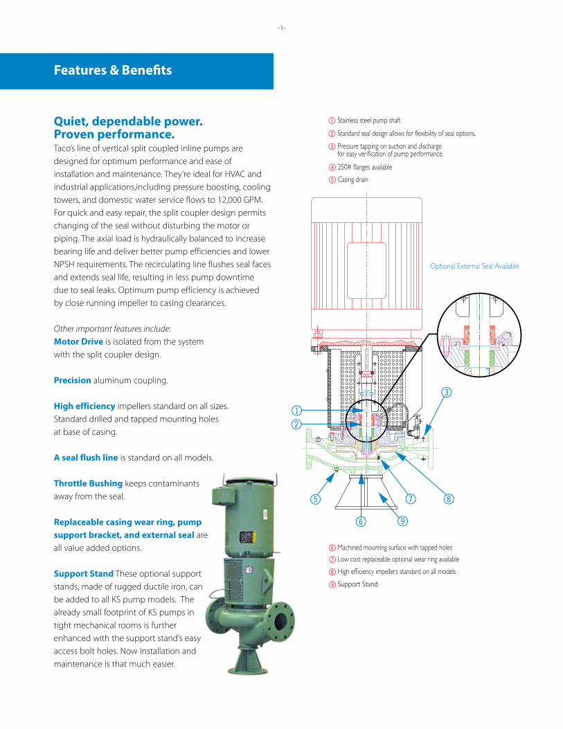
4 250# flanges available
8 High efficiency impellers standard on all models
7 Low cost replaceable optional wear ring available
6 Machined mounting surface with tapped holes
5 Casing drain
2 Standard seal design allows for flexibility of seal options.
1 Stainless steel pump shaft
3 Pressure tapping on suction and dischargefor easy verification of pump performance.
Optional External Seal Available
12
7
6
3
5 8
9
9 Support Stand
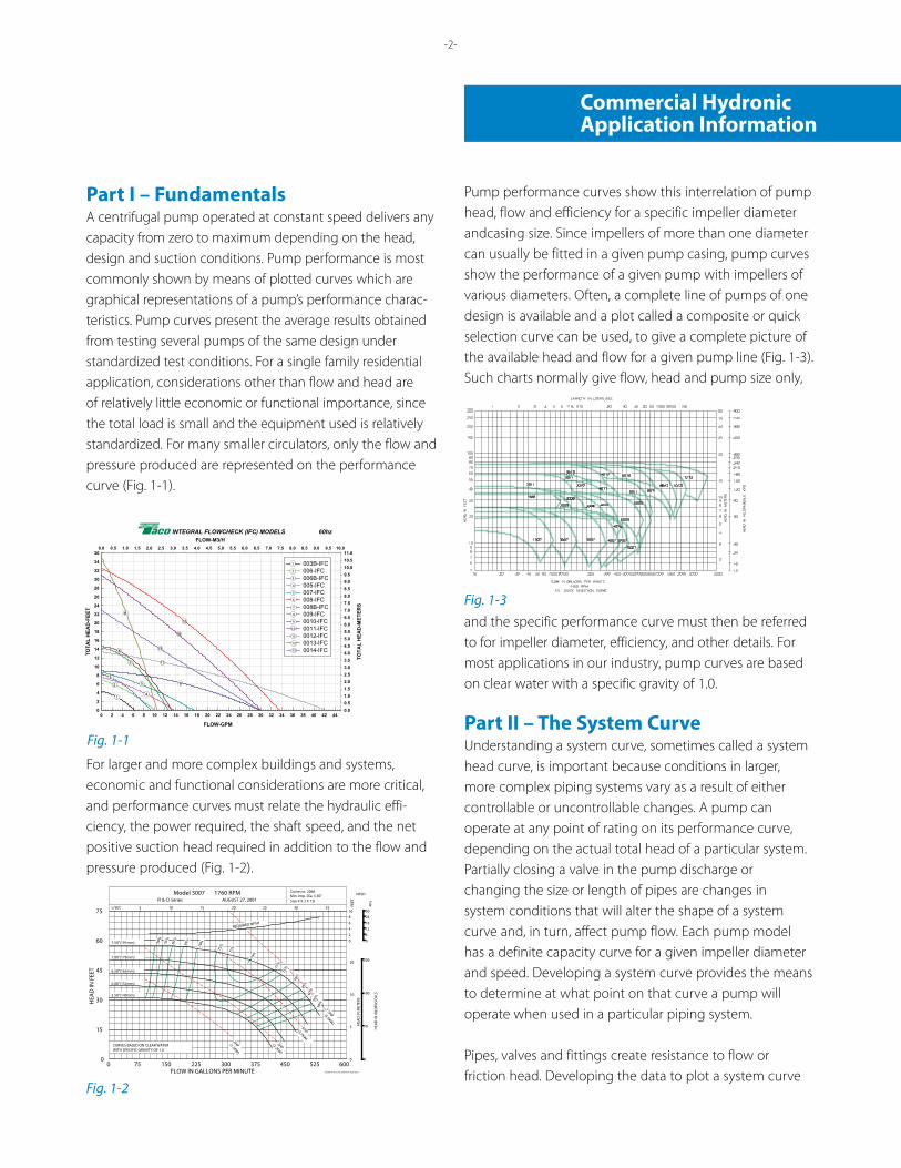
Part I – FundamentalsA centrifugal pump operated at constant speed delivers any capacity from zero to maximum depending on the head, design and suction conditions. Pump performance is most commonly shown by means of plotted curves which are graphical representations of a pump’s performance charac-teristics. Pump curves present the average results obtained from testing several pumps of the same design under standardized test conditions. For a single family residential application, considerations other than flow and head are of relatively little economic or functional importance, since the total load is small and the equipment used is relatively standardized. For many smaller circulators, only the flow and pressure produced are represented on the performance curve (Fig. 1-1).
For larger and more complex buildings and systems,economic and functional considerations are more critical, and performance curves must relate the hydraulic effi-ciency, the power required, the shaft speed, and the net positive suction head required in addition to the flow and pressure produced (Fig. 1-2).
Pump performance curves show this interrelation of pump head, flow and efficiency for a specific impeller diameter andcasing size. Since impellers of more than one diameter can usually be fitted in a given pump casing, pump curves show the performance of a given pump with impellers of various diameters. Often, a complete line of pumps of one design is available and a plot called a composite or quick selection curve can be used, to give a complete picture of the available head and flow for a given pump line (Fig. 1-3).Such charts normally give flow, head and pump size only,
and the specific performance curve must then be referred to for impeller diameter, efficiency, and other details. For most applications in our industry, pump curves are based on clear water with a specific gravity of 1.0.
Part II – The System CurveUnderstanding a system curve, sometimes called a system head curve, is important because conditions in larger, more complex piping systems vary as a result of either controllable or uncontrollable changes. A pump can operate at any point of rating on its performance curve, depending on the actual total head of a particular system. Partially closing a valve in the pump discharge or changing the size or length of pipes are changes in system conditions that will alter the shape of a system curve and, in turn, affect pump flow. Each pump model has a definite capacity curve for a given impeller diameter and speed. Developing a system curve provides the means to determine at what point on that curve a pump will operate when used in a particular piping system.
Pipes, valves and fittings create resistance to flow orfriction head. Developing the data to plot a system curve
Commercial HydronicApplication Information
-2-
Fig. 1-1FLOW-GPM
0 2 4 6 8 10 12 14 16 18 20 22 24 26 28 30 32 34 36 38 40 42 44
TOTA
L H
EAD
-FEE
T
0
2
4
6
8
10
12
14
16
18
20
22
24
26
28
30
32
34
36
FLOW-M3/H0.0 0.5 1.0 1.5 2.0 2.5 3.0 3.5 4.0 4.5 5.0 5.5 6.0 6.5 7.0 7.5 8.0 8.5 9.0 9.5 10.0
TOTA
L H
EAD
-MET
ERS
0.00.51.01.52.02.53.03.54.04.55.05.56.06.57.07.58.08.59.09.510.010.511.0
003B-IFC006-IFC006B-IFC005-IFC007-IFC008-IFC008B-IFC009-IFC0010-IFC0011-IFC0012-IFC0013-IFC0014-IFC6
2
4
1
2
3
4
5
6
7
8
9
10
11
1
3
5 9
13
8
10
11
INTEGRAL FLOWCHECK (IFC) MODELS 60hz
12
13
7
12
Fig. 1-2
10
20
10
JSA/MS 2-18-02 PC-2066 RevA ECN10627
CURVES BASED ON CLEAR WATERWITH SPECIFIC GRAVITY OF 1.0
5.50"(140mm)
0
2HP 3HP
5HP
5
7.5HP
6.00"(152mm)
6.50"(165mm)
7.00"(178mm)
7.50"(191mm)
5 10 15
REQUIRED NPSH
2
0
8
4
6
Size 4 X 3 X 7.0Min. Imp. Dia. 5.50"Curve no. 2066
20 25 30 35
0
50
100
200
6
0
24
12
18
30
77%75
%
79%
77%
75%
65%
50%
55%
60%
70%
55%
50%
60%
65%
70%
(1.5KW)
(2.2KW)
(3.7KW)
(5.6KW)
75
30
45
60
0
15
HEA
D IN
FEE
T
300FLOW IN GALLONS PER MINUTE
150750 225 450375 525 600
Model 3007 1760 RPM
L/SEC
FI & CI Series AUGUST 27, 2001
FEET
HEA
D IN
KIL
OPA
SCA
LS
HEA
D IN
MET
ERS
KPa
NPSH
Fig. 1-3
for a closed Hydronic system under pressure requires cal-culation of the total of these friction head losses. Friction tables are readily available that provide friction loss data for pipe, valves and fittings. These tables usually express the losses in terms of the equivalent length of straight pipe of the same size as the valve or fitting. Once the total system friction is determined, a plot can be made because this fric-tion varies roughly as the square of the liquid flow in the system. This plot represents the SYSTEM CURVE. By laying the system curve over the pump performance curve, the pump flow can be determined (Fig. 2–1).
Care must be taken that both pump head and frictionare expressed in feet and that both are plotted on thesame graph. The system curve will intersect the pumpperformance curve at the flow rate of the pump because this is the point at which the pump head is equal to the required system head for the same flow.
Fig. 2–2 illustrates the use of a discharge valve to change the system head to vary pump flow. Partially closing the valve shifts the operating point to a higher head or lower flow capacity. Opening the valve has the opposite effect.
Fig. 2-1
Working the system curve against the pump performance curve for different total resistance possibilities provides the system designer important information with which to make pump and motor selection decisions for each system. A system curve is also an effective tool in analyzing system performance problems and choosing appropriate correc-tive action.
In an open Hydronic system, it may be necessary to add head to raise the liquid from a lower level to a higher level. Called static or elevation head, this amount is added to the friction head to determine the total system head curve. Fig. 2–3 illustrates a system curve developed by adding static head to the friction head resistance.
Fig. 2-2
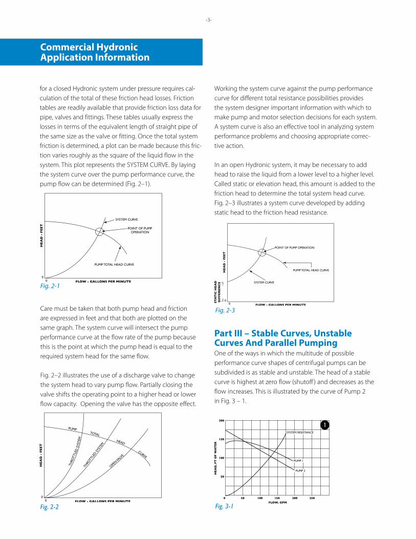
Part III – Stable Curves, UnstableCurves And Parallel PumpingOne of the ways in which the multitude of possibleperformance curve shapes of centrifugal pumps can be subdivided is as stable and unstable. The head of a stable curve is highest at zero flow (shutoff ) and decreases as the flow increases. This is illustrated by the curve of Pump 2 in Fig. 3 – 1.
Fig. 2-3
Fig. 3-1
Commercial HydronicApplication Information
-3-
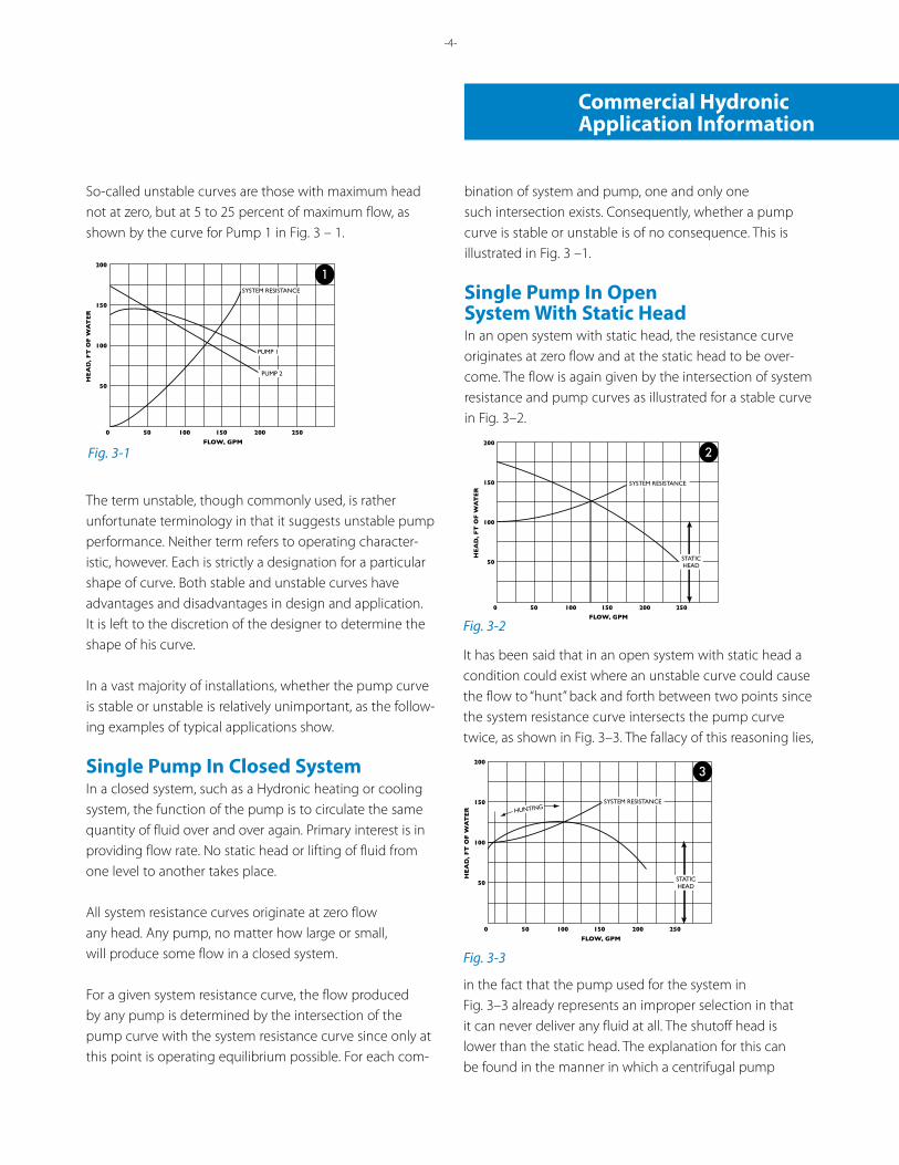
So-called unstable curves are those with maximum head not at zero, but at 5 to 25 percent of maximum flow, as shown by the curve for Pump 1 in Fig. 3 – 1.
The term unstable, though commonly used, is ratherunfortunate terminology in that it suggests unstable pump performance. Neither term refers to operating character-istic, however. Each is strictly a designation for a particular shape of curve. Both stable and unstable curves have advantages and disadvantages in design and application. It is left to the discretion of the designer to determine the shape of his curve.
In a vast majority of installations, whether the pump curve is stable or unstable is relatively unimportant, as the follow-ing examples of typical applications show.
Single Pump In Closed SystemIn a closed system, such as a Hydronic heating or cooling system, the function of the pump is to circulate the same quantity of fluid over and over again. Primary interest is in providing flow rate. No static head or lifting of fluid from one level to another takes place.
All system resistance curves originate at zero flow any head. Any pump, no matter how large or small, will produce some flow in a closed system.
For a given system resistance curve, the flow produced by any pump is determined by the intersection of the pump curve with the system resistance curve since only at this point is operating equilibrium possible. For each com-
bination of system and pump, one and only one such intersection exists. Consequently, whether a pump curve is stable or unstable is of no consequence. This is illustrated in Fig. 3 –1.
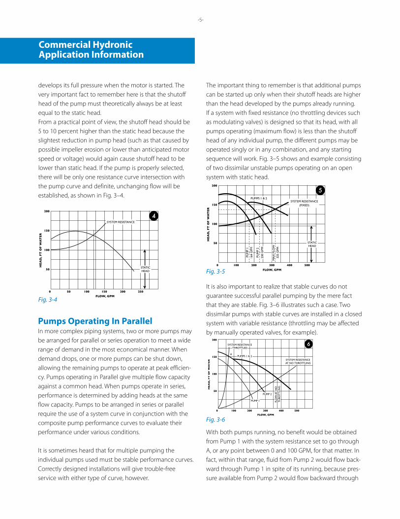
Single Pump In OpenSystem With Static HeadIn an open system with static head, the resistance curve originates at zero flow and at the static head to be over-come. The flow is again given by the intersection of system resistance and pump curves as illustrated for a stable curve in Fig. 3–2.
Fig. 3-1
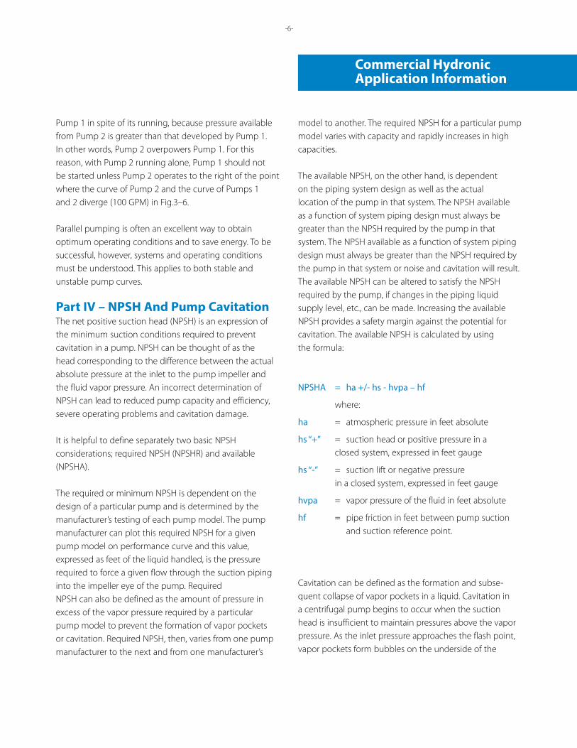
It has been said that in an open system with static head a condition could exist where an unstable curve could cause the flow to “hunt” back and forth between two points since the system resistance curve intersects the pump curve twice, as shown in Fig. 3–3. The fallacy of this reasoning lies,
in the fact that the pump used for the system in Fig. 3–3 already represents an improper selection in that it can never deliver any fluid at all. The shutoff head is lower than the static head. The explanation for this can be found in the manner in which a centrifugal pump
Fig. 3-2
2
Fig. 3-3
3
-3- -4-
Commercial HydronicApplication Information
develops its full pressure when the motor is started. The very important fact to remember here is that the shutoff head of the pump must theoretically always be at least equal to the static head.From a practical point of view, the shutoff head should be 5 to 10 percent higher than the static head because the slightest reduction in pump head (such as that caused by possible impeller erosion or lower than anticipated motor speed or voltage) would again cause shutoff head to be lower than static head. If the pump is properly selected, there will be only one resistance curve intersection with the pump curve and definite, unchanging flow will be established, as shown in Fig. 3–4.
Pumps Operating In ParallelIn more complex piping systems, two or more pumps may be arranged for parallel or series operation to meet a wide range of demand in the most economical manner. When demand drops, one or more pumps can be shut down, allowing the remaining pumps to operate at peak efficien-cy. Pumps operating in Parallel give multiple flow capacity against a common head. When pumps operate in series, performance is determined by adding heads at the same flow capacity. Pumps to be arranged in series or parallel require the use of a system curve in conjunction with the composite pump performance curves to evaluate theirperformance under various conditions.
It is sometimes heard that for multiple pumping theindividual pumps used must be stable performance curves. Correctly designed installations will give trouble-free service with either type of curve, however.
Fig. 3-4
The important thing to remember is that additional pumps can be started up only when their shutoff heads are higher than the head developed by the pumps already running.If a system with fixed resistance (no throttling devices such as modulating valves) is designed so that its head, with all pumps operating (maximum flow) is less than the shutoff head of any individual pump, the different pumps may be operated singly or in any combination, and any starting sequence will work. Fig. 3–5 shows and example consisting of two dissimilar unstable pumps operating on an open system with static head.
It is also important to realize that stable curves do notguarantee successful parallel pumping by the mere fact that they are stable. Fig. 3–6 illustrates such a case. Twodissimilar pumps with stable curves are installed in a closed system with variable resistance (throttling may be affected by manually operated valves, for example).
Fig. 3-5
With both pumps running, no benefit would be obtained from Pump 1 with the system resistance set to go through A, or any point between 0 and 100 GPM, for that matter. In fact, within that range, fluid from Pump 2 would flow back-ward through Pump 1 in spite of its running, because pres-sure available from Pump 2 would flow backward through
Fig. 3-6
5
6
-5-
4
Commercial HydronicApplication Information
Pump 1 in spite of its running, because pressure available from Pump 2 is greater than that developed by Pump 1.In other words, Pump 2 overpowers Pump 1. For this reason, with Pump 2 running alone, Pump 1 should not be started unless Pump 2 operates to the right of the point where the curve of Pump 2 and the curve of Pumps 1 and 2 diverge (100 GPM) in Fig.3–6.
Parallel pumping is often an excellent way to obtainoptimum operating conditions and to save energy. To be successful, however, systems and operating conditions must be understood. This applies to both stable and unstable pump curves.
Part IV – NPSH And Pump CavitationThe net positive suction head (NPSH) is an expression of the minimum suction conditions required to prevent cavitation in a pump. NPSH can be thought of as the head corresponding to the difference between the actual absolute pressure at the inlet to the pump impeller and the fluid vapor pressure. An incorrect determination of NPSH can lead to reduced pump capacity and efficiency, severe operating problems and cavitation damage.
It is helpful to define separately two basic NPSH considerations; required NPSH (NPSHR) and available (NPSHA).
The required or minimum NPSH is dependent on the design of a particular pump and is determined by the manufacturer’s testing of each pump model. The pump manufacturer can plot this required NPSH for a given pump model on performance curve and this value, expressed as feet of the liquid handled, is the pressure required to force a given flow through the suction piping into the impeller eye of the pump. RequiredNPSH can also be defined as the amount of pressure in excess of the vapor pressure required by a particular pump model to prevent the formation of vapor pockets or cavitation. Required NPSH, then, varies from one pump manufacturer to the next and from one manufacturer’s
model to another. The required NPSH for a particular pump model varies with capacity and rapidly increases in high capacities.
The available NPSH, on the other hand, is dependent on the piping system design as well as the actual location of the pump in that system. The NPSH available as a function of system piping design must always be greater than the NPSH required by the pump in that system. The NPSH available as a function of system piping design must always be greater than the NPSH required by the pump in that system or noise and cavitation will result. The available NPSH can be altered to satisfy the NPSH required by the pump, if changes in the piping liquid supply level, etc., can be made. Increasing the available NPSH provides a safety margin against the potential for cavitation. The available NPSH is calculated by using the formula:
NPSHA = ha +/- hs - hvpa – hf
where:
ha = atmospheric pressure in feet absolute
hs “+” = suction head or positive pressure in a closed system, expressed in feet gauge
hs “-” = suction lift or negative pressure in a closed system, expressed in feet gauge
hvpa = vapor pressure of the fluid in feet absolute
hf = pipe friction in feet between pump suction and suction reference point.
Cavitation can be defined as the formation and subse-quent collapse of vapor pockets in a liquid. Cavitation in a centrifugal pump begins to occur when the suction head is insufficient to maintain pressures above the vapor pressure. As the inlet pressure approaches the flash point, vapor pockets form bubbles on the underside of the
-5- -6-
Commercial HydronicApplication Information
ADDITIONAL OPTIONS
Filters Cuno 5 Micron
Separators Kynar Cyclone Separator
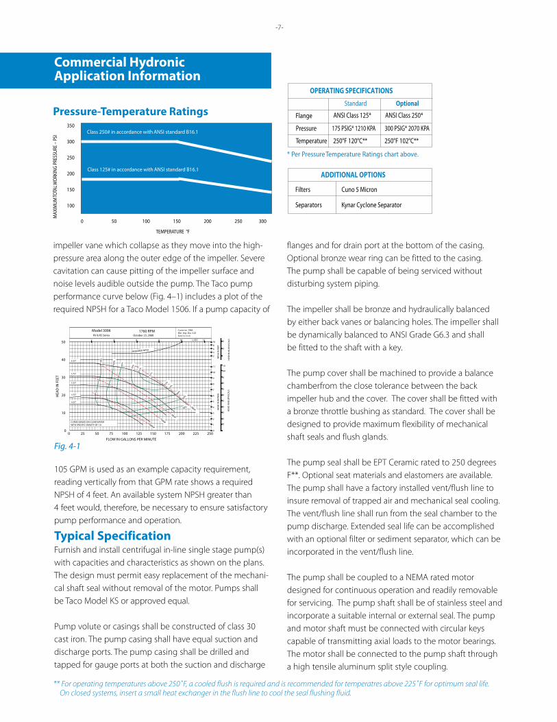
OPERATING SPECIFICATIONS Standard Optional
Pressure 175 PSIG* 1210 KPA 300 PSIG* 2070 KPA
Temperature 250°F 120°C** 250°F 102°C**
* Per Pressure Temperature Ratings chart above.
Pressure-Temperature Ratings350
300
250
200
150
100
0 50 100 150 200 250 300
Class 250# in accordance with ANSI standard B16.1
Class 125# in accordance with ANSI standard B16.1
MAX
IMUM
TOTA
L WOR
KING
PRE
SSUR
E – P
SI
TEMPERATURE °F
Flange ANSI Class 125* ANSI Class 250*
impeller vane which collapse as they move into the high-pressure area along the outer edge of the impeller. Severe cavitation can cause pitting of the impeller surface and noise levels audible outside the pump. The Taco pump performance curve below (Fig. 4–1) includes a plot of the required NPSH for a Taco Model 1506. If a pump capacity of
Fig. 4-1
Min. Imp. Dia. 4.25Size 3 x 3 x 6
Curve no. 1966
October 23, 2000KV & KS Series1760 RPMModel 3006
CURVES BASED ON CLEAR WATERWITH SPECIFIC GRAVITY OF 1.0
HEA
D IN
MET
ERS
0
RLB 10-23-00 PC-1966 PC1966 REV A KV/KS 3006 1760 ECN9110
2
4
6
8
10
REQUIRED NPSH
HEA
D IN
KIL
OPA
SCA
LS
40
80
60
20
0
L/SEC2 4 6 8 10 12
2
4
6
8
10
NPS
H IN
FEE
T
NPS
H IN
KIL
OPA
SCA
LS
6
18
30
6.25"
5.75"
5.25"
4.75"
4.25"
50%
60%
65%
70%
72%
73%
72%
70%
65%
60%
50%
1BHP.75BHP
.50BHP
1.5BHP
100
505
303
101
707
909
11011
0 25 50 75 100 125 150 175 200 225 2500
10
20
30
40
50
HEA
D IN
FEE
T
FLOW IN GALLONS PER MINUTE
Fig. 4-1
105 GPM is used as an example capacity requirement, reading vertically from that GPM rate shows a required NPSH of 4 feet. An available system NPSH greater than 4 feet would, therefore, be necessary to ensure satisfactory pump performance and operation.
Typical SpecificationFurnish and install centrifugal in-line single stage pump(s) with capacities and characteristics as shown on the plans. The design must permit easy replacement of the mechani-cal shaft seal without removal of the motor. Pumps shall be Taco Model KS or approved equal.
Pump volute or casings shall be constructed of class 30 cast iron. The pump casing shall have equal suction and discharge ports. The pump casing shall be drilled and tapped for gauge ports at both the suction and discharge
flanges and for drain port at the bottom of the casing. Optional bronze wear ring can be fitted to the casing. The pump shall be capable of being serviced without disturbing system piping.
The impeller shall be bronze and hydraulically balanced by either back vanes or balancing holes. The impeller shall be dynamically balanced to ANSI Grade G6.3 and shall be fitted to the shaft with a key.
The pump cover shall be machined to provide a balance chamberfrom the close tolerance between the back impeller hub and the cover. The cover shall be fitted with a bronze throttle bushing as standard. The cover shall be designed to provide maximum flexibility of mechanical shaft seals and flush glands.
The pump seal shall be EPT Ceramic rated to 250 degrees F**. Optional seat materials and elastomers are available. The pump shall have a factory installed vent/flush line to insure removal of trapped air and mechanical seal cooling. The vent/flush line shall run from the seal chamber to the pump discharge. Extended seal life can be accomplished with an optional filter or sediment separator, which can be incorporated in the vent/flush line.
The pump shall be coupled to a NEMA rated motor designed for continuous operation and readily removable for servicing. The pump shaft shall be of stainless steel and incorporate a suitable internal or external seal. The pump and motor shaft must be connected with circular keys capable of transmitting axial loads to the motor bearings. The motor shall be connected to the pump shaft through a high tensile aluminum split style coupling.
ADDITIONAL OPTIONS
Filters Cuno 5 Micron
Separators Kynar Cyclone Separator
OPERATING SPECIFICATIONS Standard Optional
Pressure 175 PSIG* 1210 KPA 300 PSIG* 2070 KPA
Temperature 250°F 120°C** 250°F 102°C**
* Per Pressure Temperature Ratings chart above.
Pressure-Temperature Ratings350
300
250
200
150
100
0 50 100 150 200 250 300
Class 250# in accordance with ANSI standard B16.1
Class 125# in accordance with ANSI standard B16.1
MAX
IMUM
TOTA
L WOR
KING
PRE
SSUR
E – P
SI
TEMPERATURE °F
Flange ANSI Class 125* ANSI Class 250*
** For operating temperatures above 250˚F, a cooled flush is required and is recommended for temperatres above 225˚F for optimum seal life. On closed systems, insert a small heat exchanger in the flush line to cool the seal flushing fluid.
-7-
Commercial HydronicApplication Information
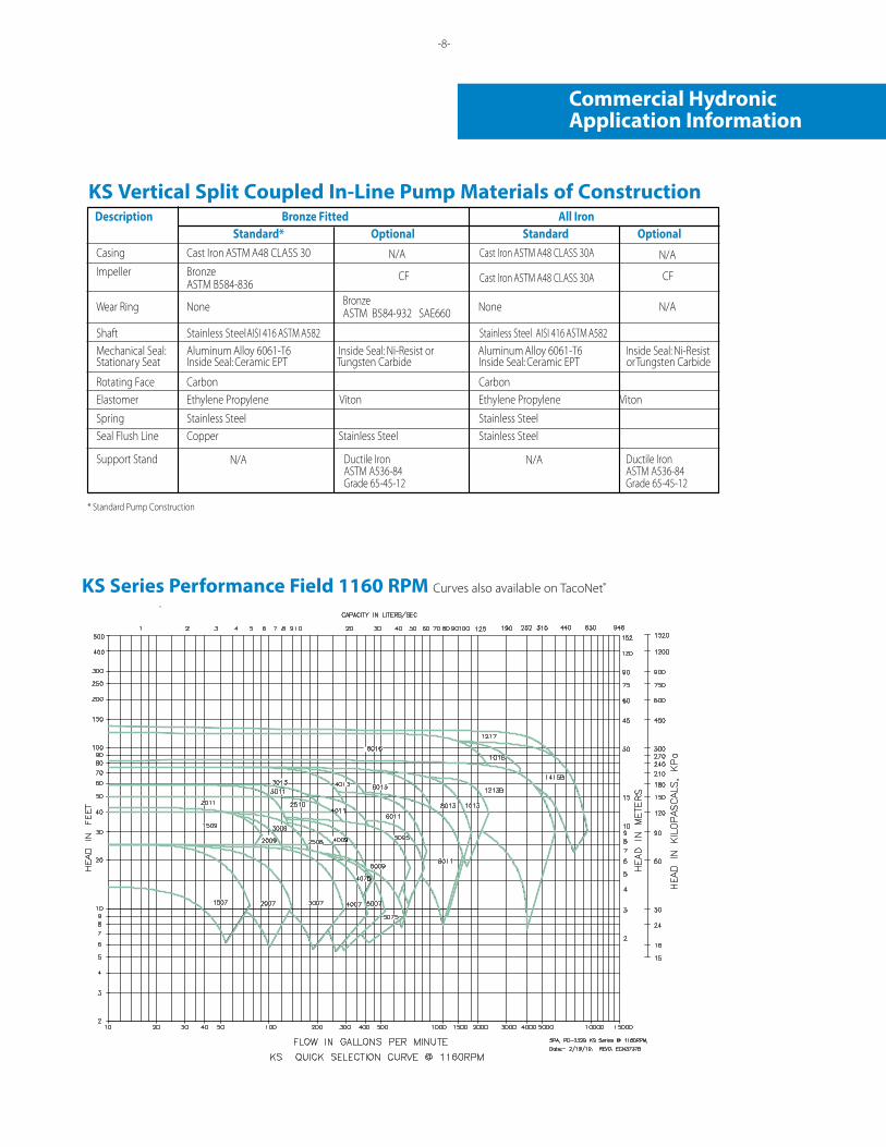
KS Series Performance Field 1160 RPM Curves also available on TacoNet®
KS Vertical Split Coupled In-Line Pump Materials of Construction
Standard* Optional Standard OptionalCasing Cast Iron ASTM A48 CLASS 30 Cast Iron ASTM A48 CLASS 30A Impeller Bronze
ASTM B584-836CF CF Cast Iron ASTM A48 CLASS 30A
Wear Ring None Bronze ASTM B584-932 SAE660
Ductile IronASTM A536-84Grade 65-45-12
Ductile IronASTM A536-84Grade 65-45-12
None N/A
N/A N/A
N/A N/A
Shaft Stainless Steel AISI 416 ASTM A582 Stainless Steel AISI 416 ASTM A582 Mechanical Seal: Aluminum Alloy 6061-T6 Inside Seal: Ni-Resist or Aluminum Alloy 6061-T6 Inside Seal: Ni-ResistStationary Seat Inside Seal: Ceramic EPT Tungsten Carbide Inside Seal: Ceramic EPT or Tungsten Carbide
Rotating Face
Carbon
CarbonElastomer
Ethylene Propylene
Viton
Ethylene Propylene
Viton
Spring
Stainless Steel
Stainless SteelSeal Flush Line
Support Stand
Copper Stainless Steel Stainless Steel
* Standard Pump Construction
Description Bronze Fitted All Iron
-7- -8-
Commercial HydronicApplication Information
-9-
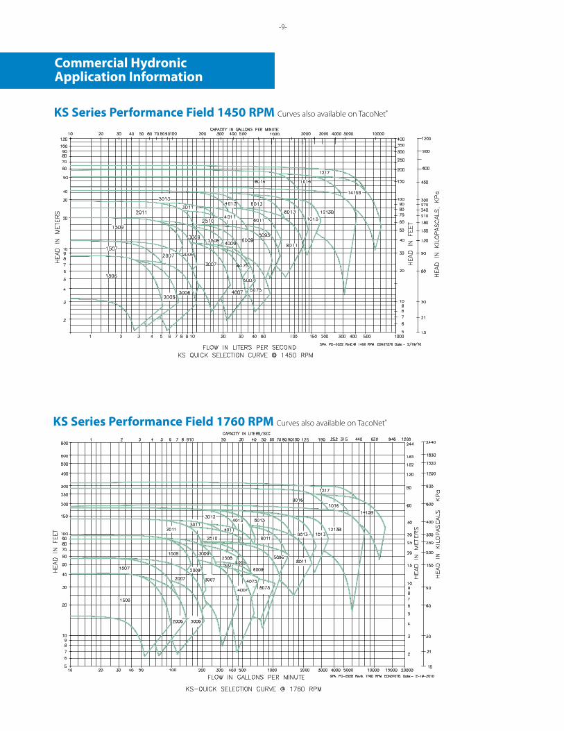
KS Series Performance Field 1450 RPM Curves also available on TacoNet®
KS Series Performance Field 1760 RPM Curves also available on TacoNet®
Commercial HydronicApplication Information
-9- -10-
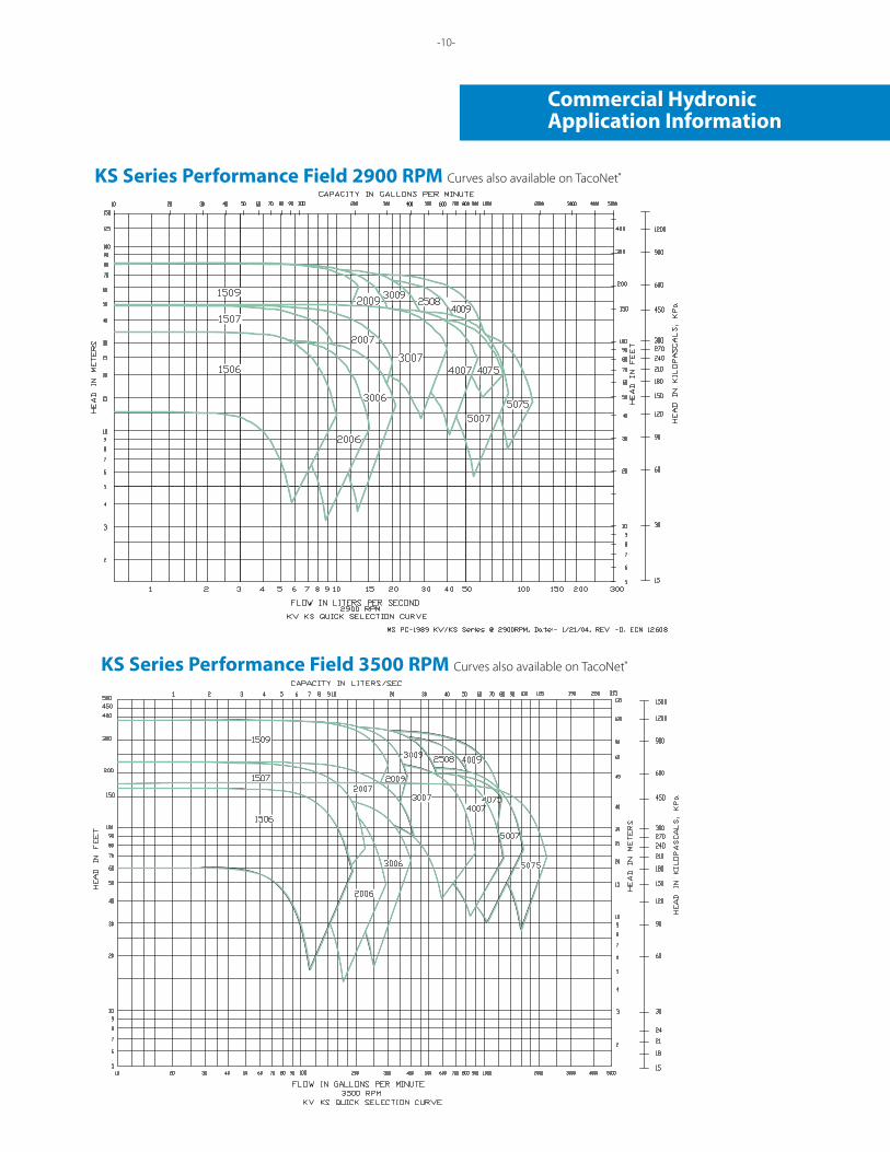
KS Series Performance Field 3500 RPM Curves also available on TacoNet.
KS Series Performance Field 2900 RPM Curves also available on TacoNet®
KS Series Performance Field 3500 RPM Curves also available on TacoNet®
Commercial HydronicApplication Information
-11-
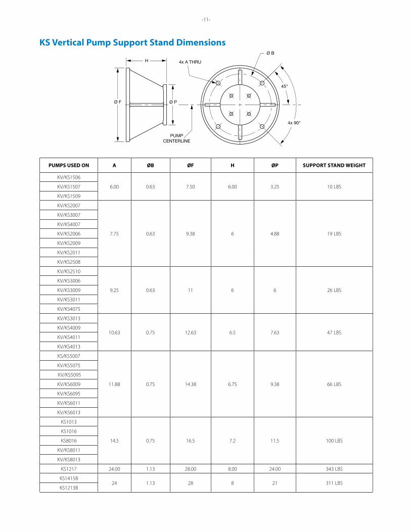
KS Vertical Pump Support Stand Dimensions
PUMPCENTERLINE
Ø B
Ø F Ø P
H
45°
4x 90°
4x A THRU
PUMPS USED ON A ØB ØF H ØP SUPPORT STAND WEIGHT
KV/KS1506
6.00 0.63 7.50 6.00 3.25 10 LBSKV/KS1507
KV/KS1509
KV/KS2007
7.75 0.63 9.38 6 4.88 19 LBS
KV/KS3007
KV/KS4007
KV/KS2006
KV/KS2009
KV/KS2011
KV/KS2508
KV/KS2510
9.25 0.63 11 6 6 26 LBS
KV/KS3006
KV/KS3009
KV/KS3011
KV/KS4075
KV/KS3013
10.63 0.75 12.63 6.5 7.63 47 LBSKV/KS4009
KV/KS4011
KV/KS4013
KS/KS5007
11.88 0.75 14.38 6.75 9.38 66 LBS
KV/KS5075
KV/KS5095
KV/KS6009
KV/KS6095
KV/KS6011
KV/KS6013
KS1013
14.5 0.75 16.5 7.2 11.5 100 LBS
KS1016
KS8016
KV/KS8011
KV/KS8013
KS1217 24.00 1.13 28.00 8.00 24.00 343 LBS
KS1415B24 1.13 28 8 21 311 LBS
KS1213B
-12-
Commercial HydronicApplication Information
MODEL NO“KS”
MOTORFRAME
SIZE
H P. FOR 3 PHASEO.D.P. MOTORS PRESSURE CLASS-125# PRESSURE CLASS-250#
E MAX. J DIA1160 1760 3500 A B A B C D F G
1.5 X 1.5 X 6(KS1506)
143 - 1 -
7.50(191 MM)
7.50(191MM)
7.75(197MM)
7.75(197MM)
4.49(114MM)
15.08(383MM)
4.13(105MM)
4.63(118MM)
13.05(331MM) 7.05
(179MM)145 - 1-1/2 2 & 3 14.05
(357MM)
182 - - 5 15.64(397MM) 8.49
(216MM)184 - - 7-1/2 16.68
(424MM)
2 X 2 X 6(KS2006)
143 - 1 -
7.50(191 MM)
8.00(203MM)
7.75(197MM)
8.25(210MM)
3.91(99MM)
14.54(369MM)
4.41(112MM)
5.14(131 MM)
13.05(331 MM) 7.05
(179MM)145 - 1-1/2 2 & 3 14.05
(357MM)
182 - - 5 15.64(397MM) 8.49
(216MM)184 - - 7-1/2 16.68
(424MM)
213 - - 10 19.13(486MM)
10.18(259MM)
3 X 3 X 6)(KS3006)
143 - 1 -
8.50(216MM)
10.00(254MM)
8.87(225MM)
10.37(263MM)
4.97(126MM)
15.56(395MM)
4.67(119MM)
5.56(141MM)
13.05(331 MM) 7.05
(179MM)145 - 1-1/2 3 14.05
(357MM)
182 - - 5 15.64(397MM)8.49
(216MM)184 - - 7-1/2 16.68(424MM)
213 - - 10 19.13(486MM) 10.18
(259MM)215 - - 15 20.63
(524MM)
1.5 X 1.5 X 7(KS1507)
143 3/4 1 -
8.00(203MM)
8.00(203MM)
8.31(211 MM)
8.31(211 MM)
4.13(105MM)
14.85(377MM)
4.88(124MM)
5.16(131 MM)
13.05(331MM) 7.05
(179MM)145 - 1-1/2 & 2 - 14.05
(357MM)
182 - - 5 15.64(397MM) 8.49
(216MM)184 - - 7-1/2 16.68
(424MM)
213 - - 10 19.13(486MM) 10.18
(259MM)215 - - 15 20.63
(524MM)
2 X 2 X 7(KS2007)
143 3/4 1 -
8.50(216MM)
8.50(216MM)
8.76(223MM)
8.76(223MM)
3.94(100MM)
14.70(373MM)
4.88(124MM)
5.45(138MM)
13.05(331MM) 7.05
(179MM)145 1 1-1/2 & 2 - 14.05
(357MM)
182 - 3 - 15.64(397MM) 8.49
(216MM)184 - - 7-1/2 16.68
(424MM)
213 - - 10 19.13(4861MM) 10.18
(259MM)215 - - 15 20.63
(524MM)
254 - - 2017.94
(456MM)
24.36(619MM) 12.88
(327MM)256 - - 25 26.11
(663MM)
3 X 3 X 7( KS3007)
143 3/4 - -
10.00(254MM)
10.00(254MM)
10.37(263MM)
10.37(263MM)
6.30(160MM)
16.96(431MM)
5.29(134MM)
6.31(160MM)
13.05(331MM) 7.05
(179MM)145 1 1-1/2 & 2 - 14.05 (357MM)
182 1-1/2 3 - 15.64 (397MM)8.49
(216MM)184 - 5 - 16.68 (424MM)
213 - 7-1/2 10 19.13 (486MM)10.18
(259MM)215 - - 15 20.63 (524MM)
254 - - 2020.20
(513MM)
24.36 (619MM)12.88
(327MM)256 - - 25 26.11 (663MM)
284 - - 3021.95
(558MM)
27.94 (710MM)14.63
(372MM)286 - - 40 29.14 (740MM)
4 X 4 X 7(KS 4075)
145 1 - -
11.81(300MM)
10.81(274MM)
12.12(307MM)
11.12(282MM)
6.94(176MM)
18.40(467MM)
5.61(142MM)
6.99(177MM)
14.05 (357MM) 7.05(179MM)
182 1-1/2 - - 15.64(397MM)
8.49(216MM)184 2 5 - 16.68 (424MM)
213 3 7-1/2 - 19.13 (486MM) 10.18(259MM)
284 - - 3021.63
(549MM)
27.94 (710MM)14.63(372MM)
286 - - 40 29.14 (740MM)
324 - - 5023.38
(593MM)
31.07 (789MM)16.50(419MM)
326 - - **60 32.57 (827MM)
4 X 4 X 7(KS4007)
143 3/4 - -
11.00(279MM)
11.00(279MM)
11.32(288MM)
11.32(288MM)
6.59(167MM)
17.64(448MM)
5.64(143MM)
6.80(173MM)
13.05 (331MM)7.05(179MM)
145 1 2 - 14.05 (357MM)
182 1-1/2 3 - 15.64 (397MM)8.49(216MM)
184 2 5 - 16.68 (424MM)
213 - 7-1/2 - 9 19.13(486MM)10.18(259MM)
215 - - 15
20.88(530MM)
20.63(524MM)
254 - - 20 24.36(619MM)12.88(327MM)
256 - - 25 26.11(663MM)
284 - - 30 27.94(710MM)14.63(372MM)
286 - - 40 29.14(740MM)
324 - - 50 22.63(575MM 31.07(789MM) 16.50(419MM)
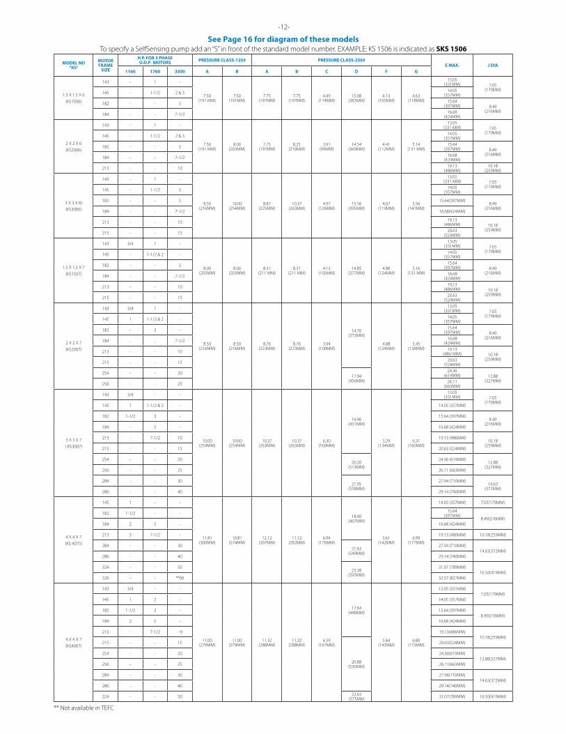
See Page 16 for diagram of these models
** Not available in TEFC
To specify a SelfSensing pump add an “S” in front of the standard model number. EXAMPLE: KS 1506 is indicated as SKS 1506
-13-
MODELNO.“KS”
FRAMEMOTOR
SIZE
H.P. FOR 3 PHASEO.D.P. MOTORS PRESSURE CLASS-125# PRESSURE CLASS-250#
E MAX. J DIA1160 1760 3500 A B A B C D F G
5 X 5 X 7(KS5007)
145 1 - -
13.00(330MM)
11.00(279MM)
13.44(341MM)
11.44(291MM)
6.63(168MM)
18.02(458MM)
6.42(163MM)
7.91(201MM)
14.05(357MM) 7.05(179MM)
182 1-1/2 3 - 15.64(397MM)8.49(216MM)
184 2 5 - 16.68(424MM)
213 3 7-1/2 - 19.13(486MM)10.18 (259MM)
215 - 10 - 20.63(524MM)
254 - - 20
21.26(540MM)
24.36(619MM)12.88(327MM)
256 - - 25 26.11(663MM)
284 - - 30 27.94(710MM)14.63(372MM)
286 - - 40 29.14(740MM)
324 - - 50 23.01(584MM)
31.07(789MM)16.50(419MM)
326 - - **60 32.57(827MM)
5 X 5 X 7(KS5075)
145 1 - -
14.00(355MM)
11.00(279MM)
14.44(366MM)
11.44(291MM)
8.07(205MM)
19.65(499MM)
6.31(160MM)
8.10(205MM)
14.05(357MM) 7.05(179MM)
182 1-1/2 3 - 15.64(397MM)8.49(216MM)
184 2 5 - 16.68(424MM)
213 3 7-1/2 - 19.13(486MM)10.18(259MM)
215 - 10 - 20.63(524MM)
284 - - 3022.89(581MM)
27.94(710MM)14.63(372MM)
286 - - 40 29.14(740MM)
324 - - 5024.64(625MM)
31.07(789MM)16.50(419MM)
326 - - **60 32.57(827MM)
364 - - ***75 25.08(637MM) 34.40(877MM) 18.25(464MM)
2.5 X 2.5 X 8(KS 2508)
145 1 - -
9.56(242MM)
9.00(228MM)
9.88(250MM)
9.31(236MM)
5.88(149MM)
16.70(424MM)
6.10(155MM)
6.99(177MM)
14.05(357MM) 7.05(179MM)
182 1-1/2 3 - 15.64(397MM)8.49(216MM)
184 2 5 - 16.68(424MM)
213 3 7-1/2 - 19.13(486MM)10.18(259MM)
215 - 10 - 20.63(524MM)
284 - - 3019.47(494MM)
27.94(710MM)14.63(372MM)
286 - - 40 29.14(740MM)
324 - - 5021.22(539MM)
31.07(789MM)16.50(419MM)
326 - - **60 32.57(827MM)
364 - - ***75 22.13(562MM) 34.40(877MM) 18.25(464MM)
1.5 X1.5 X 9(KS1509)
143 3/4 - -
8.00(203MM)
8.00(203MM)
8.31(211MM)
8.31(211MM)
4.36(111MM)
15.05(382mm)
5.72(145MM) 6.22(158MM)
13.05(331MM)7.05(179MM)
145 1 1-1/2 & 2 - 14.05(357MM)
182 1-1/2 3 - 15.64(397MM)8.49(216MM)
184 - 5 - 16.68(424MM)
213 - - 10 19.13(486MM)10.18(259MM)
215 - - 15 20.63(524MM)
254 - - 20
17.335(440mm)
24.36(619MM)12.88(327MM)
256 - - 25 26.11(663MM)
284 - - 30 27.94(710MM)14.63(372MM)
286 - - 40 29.14(740MM)
2 X 2 X 9(KS2009)
143 3/4 - -
9.00(229MM)
10.00(254MM)
9.25(235MM)
10.25(260MM)
3.94(100MM)
14.72(374MM)
5.72(145MM)
6.22(158MM)
13.05(331MM)7.05(179MM)
145 1 1-1/2 & 2 - 14.05(357MM)
182 1-1/2 3 - 15.64(397MM)8.49(216MM)
184 - 5 - 16.68(424MM)
213 - 7-1/2 - 19.13(486MM10.18(259MM)
215 - - 15 20.63(524MM)
254 - - 20
17.49(444MM)
24.36(619MM)12.88(327MM)
256 - - 25 26.11(663MM)
284 - - 30 27.94(710MM)14.63(372MM)
286 - - 40 29.14(740MM)
3 X 3 X 9(KS3009)
143 3/4 - -
10.00(254MM)
11.00(279MM)
10.37(263MM)
11.37(289MM)
5.19(132MM)
15.90(404MM)
5.94(151MM)
6.53(166MM)
13.05(331MM)7.05(179MM)
145 1 1-1/2 & 2 - 14.05(357MM)
182 1-1/2 3 - 15.64(397MM)8.49(216MM)
184 2 5 - 16.68(424MM)
213 - 7-1/2 - 19.13(486MM)10.18(259MM)
215 - - 15 20.63(524MM)
254 - - 20
18.67(474MM)
24.36(619MM)12.88(327MM)
256 - - 25 26.11(663MM)
284 - - 30 27.94(710MM)14.63(372MM)
286 - - 40 29.14(740MM)
324 - - 50 20.42 519MM 31.07(789MM) 16.50(419MM)
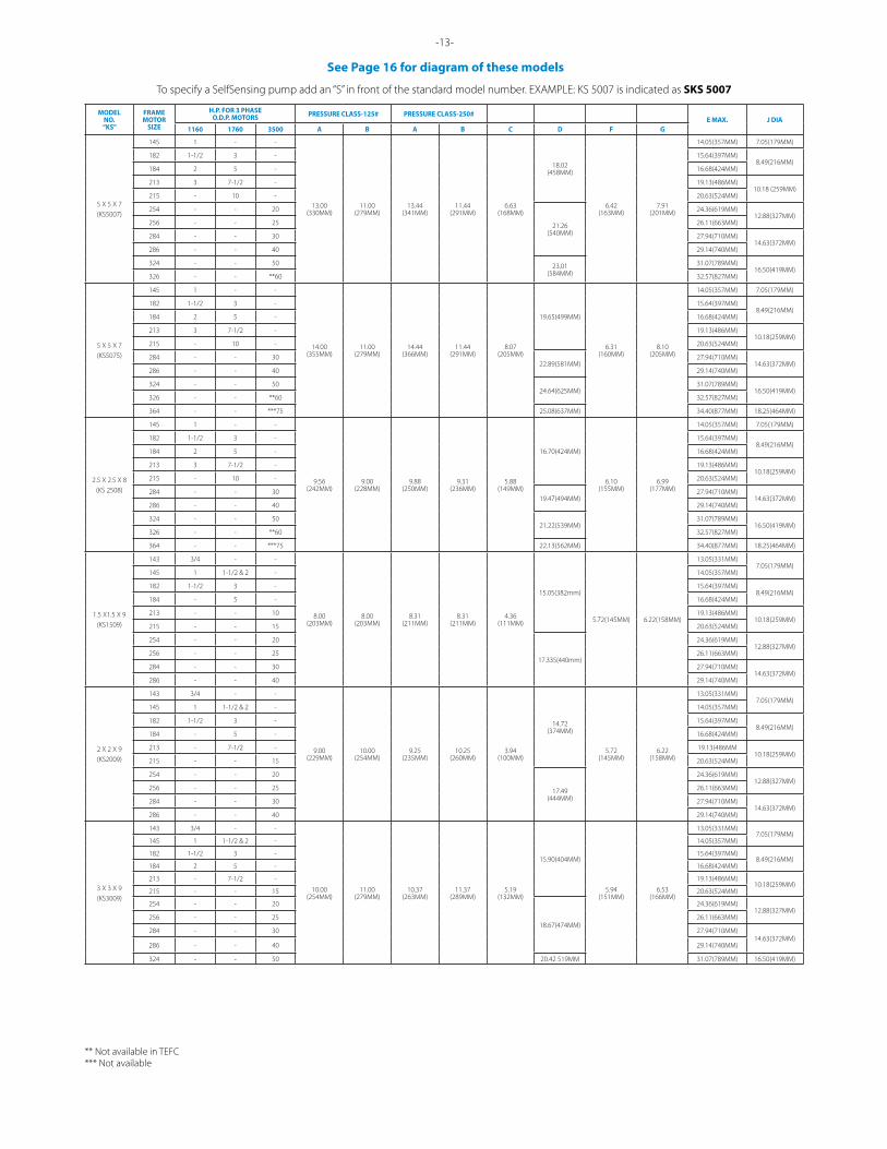
See Page 16 for diagram of these models
** Not available in TEFC*** Not available
-14-
See Page 16 for diagram of these models
To specify a SelfSensing pump add an “S” in front of the standard model number. EXAMPLE: KS 5007 is indicated as SKS 5007
-13-
See Page 16 for diagram of these models
-14-
MODELNO.“KS”
FRAMEMOTOR
SIZE
H.P. FOR 3 PHASEO.D.P. MOTORS PRESSURE CLASS-125# PRESSURE CLASS-250#
E MAX. J DIA1160 1760 3500 A B A B C D F G
4X4X9(KS4009)
145 1 - -
11.00(279MM)
13.00(330MM)
11.32(288MM)
13.32(338MM)
6.19(157MM)
17.01(432MM)
6.28(160MM)
7.25(184MM)
14.05(357MM) 7.05(179MM)
182 1-1/2 3 - 15.64(397MM)8.49(216MM)
184 2 5 - 16.68(424MM)
213 3 7 1/2 - 19.13(486MM)10.18(259MM)
215 - 10 - 20.63(524MM)
254 - 15 25
19.78(502MM)
24.36(619MM) 12.88(327MM)
284 - - 30 27.94(710MM)14.63(372MM)
286 - - 40 29.14(740MM)
324 - - 5021.53
(547MM)
31.07(789MM)16.50(419MM)
326 - - **60 32.57(827MM)
5X5X9(KS5095)
213 3 - -
14.00(355MM)
11.00(279MM)
14.44(366MM)
11.44(290MM)
7.34(186MM)
18.68(474MM)
7.37(187MM)
9.08(230MM)
19.13(486MM)10.18(259MM)
215 5 10 - 20.63(524MM)
254 7-1/2 15 -
21.45(544MM)
24.36(619MM)12.88(327MM)
256 - 20 - 26.11(663MM)
284 - 25 - 27.94(710MM) 14.63(372MM)
6X6X9(KS6009)
184 2 5 -
13.50(343MM)
15.50(394MM)
13.82(351MM)
15.82(402MM)
6.60(168MM)
17.87(454MM)
7.62(194MM)
9.31(236MM)
16.68(424MM) 8.49(216MM)
213 3 7-1/2 - 19.13(486MM)10.18(259MM)
215 5 10 - 20.63(524MM)
254 7-1/2 15 -20.64
(524MM)
24.36(619MM)12.88(327MM)
256 - 20 - 26.11(663MM)
2.5 X 2.5 X 10(KS2510)
184 2 5 -
11.25(285MM)
9.75(247MM)
11.56(293MM)
10.06(255MM)
6.79(172MM)
17.73(450MM)
7.06(179MM)
7.71(195MM)
16.68(424MM) 8.49(216MM)
213 3 7-1/2 - 19.13(486MM)10.18(259MM)
215 5 10 - 20.63(524MM)
254 - 15 -20.55
(522MM)
24.36(619MM)12.88(327MM)
256 - 20 - 26.11(663MM)
2 X 2 X 11(KS2011)
145 1 - -
10.50(267MM)
10.85(276MM)
10.75(273MM)
11.10(282MM)
3.94(100MM)
14.67(373MM)
7.06(179MM)
7.12(181MM)
14.05(357MM) 7.05(179MM)
182 1-1/2 3 - 15.64(397MM)8.49(216MM)
184 2 5 - 16.68(424MM)
213 3 7-1/2 - 19.13(486MM)10.18(259MM)
215 - 10 - 20.63(524MM)
3 X 3 X 11(KS3011)
145 - - -
11.50(292MM)
13.00(330MM)
11.88(302MM)
13.38(340MM)
6.00(152MM)
16.84(428MM) 7.10
(180MM)7.89
(200MM)
14.05(357MM) 7.05(179MM)
182 1-1/2 - - 15.64(397MM)8.49(216MM)
184 2 5 - 16.68(424MM)
213 3 7-1/2 - 19.13(486MM)10.18(259MM)
215 5 10 - 20.63(524MM)
254 - 15 - 19.67(500MM) 24.36(619MM) 12.88(327MM)
4 X 4 X 11(KS4011)
184 2 - -
13.50(343MM)
15.00(381MM)
13.81(351MM)
15.31(389MM)
6.29(160MM)
17.33(440MM)
7.74(197MM)
8.82(224MM)
16.68(424MM) 8.49(216MM)
213 3 7-1/2 - 19.13(486MM)10.18(259MM)
215 5 10 - 20.63(524MM)
254 7-1/2 15 - 20.15(512MM)
24.36(619MM)12.88(327MM)
256 - 20 - 26.11(663MM)
6 X 6 X 11(KS6011)
213 3 - -
16.00(406MM)
17.50(445MM)
16.32 (415MM )
17.82 (453MM)
7.82(199MM)
19.09(485mm)
8.61 (219MM)
10.25(260MM)
19.13(486MM)10.18(259MM)
215 5 10 - 20.63(524MM)
254 7-1/2 15 -
21 .88(556MM)
24.36(619MM)12.88(327MM)
256 10 20 - 26.11(663MM)
284 - 25 - 27.94(710MM)14.63(372MM)
286 - 30 - 29.14(740MM)
324 - 40 - 23.66(601MM) 31.07(789MM) 16.50(419MM
8 X 8 X 11(KS8011)
215 5 - -
20.00(508MM)
19.50(495MM)
20.50(521MM)
20.00(508MM)
9.25(235MM)
19.09(485MM)
9.57(243MM)
12.75(324MM)
20.63(524MM) 10.18(259MM)
254 7-1/2 - -
23.84(606mm)
24.36(619MM)12.88(327MM)
256 10 20 - 26.11(663MM)
284 15 25 - 27.94(710MM)14.63(372MM)
286 - 30 - 29.14(740MM)
324 - 40 - 25.59(650MM)
31.07(789MM)16.50(419MM)
326 - 50 - 32.57(827MM)
3 X 3 X 13(KS3013)
184 2 - -
13.63(346MM) 14.13(359MM)
14.00(356MM)
14.50(368MM)
5.93(151MM)
16.98(431 MM)
8.31(211MM)
8.77(223MM)
16.68(424MM) 8.49(216MM)
213 3 - - 19.13(486MM)10.18(259MM)
215 5 10 - 20.63(524MM)
254 7-1/2 15 -19.75
(502MM)
24.36(619MM)12.88(327MM)
256 - 20 - 26.11(663MM)
284 - 25 - 27.94(710MM) 14.63(372MM)
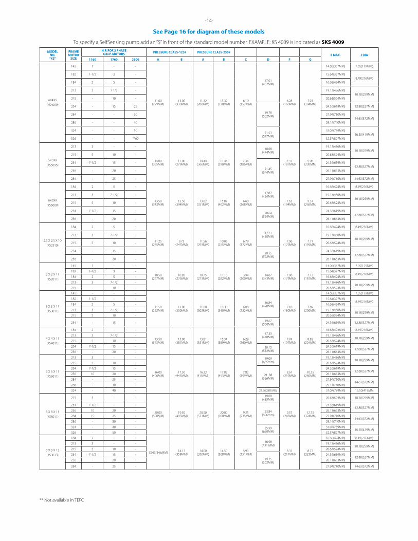
See Page 16 for diagram of these models
** Not available in TEFC
To specify a SelfSensing pump add an “S” in front of the standard model number. EXAMPLE: KS 4009 is indicated as SKS 4009
See Page 16 for diagram of these models
MODELNO.“KS”
FRAMEMOTOR
SIZE
H.P. FOR 3 PHASEO.D.P. MOTORS PRESSURE CLASS-125# PRESSURE CLASS-250#
E MAX. J DIA1160 1760 3500 A B A B C D F G
4 X 4 X 13(KS4013)
184 2 - -
15.50(394MM) 15.50(394MM) 15.81(402MM) 15.81(402MM) 6.23(158MM)
17.32(440MM)
8.53(217MM) 9.52(242MM)
16.68(424MM) 8.49(216MM)
213 3 7 1/2 - 19.13(486MM)10.18(259MM)
215 5 10 - 20.63(524MM)
254 7 1/2 15 -20.09(510MM)
24.36(619MM)12.88(327MM)
256 10 20 - 26.11(663MM)
284 - 25 -21.84(555MM)
27.94(710MM)14.63(372MM)
286 - 30 - 29.14(740MM)
6 X 6 X 13(KS6013)
215 5 - -
17.00(432MM) 17.00(432MM) 17.32(440MM) 17.32(440MM) 8.17(208MM)
19.61(498MM)
9.30(236MM) 11.48(292MM)
20.63(524MM) 10.18(259MM)
254 7-1/2 15 -
22.38(568MM)
24.36(619MM)12.88(327MM)
256 10 20 - 26.11(663MM)
284 15 25 - 27.94(710MM)14.63(372MM)
286 20 30 - 29.14(740MM)
324 - 40 -24.13(613MM)
31.07(789MM)16.50(419MM)
326 - 50 - 32.57(827MM)
364 - 60 - 25.04(636MM) 34.40(877MM) 18.25(464MM)
8 X 8 X 13(KS8013)
256 10 - -
20.00(508MM) 21.00(533MM) 20.50(521MM) 21.50(546MM) 9.25(235MM)
23.68(601MM)
10.44(265MM) 13.40(340MM)
26.11(663MM) 12.88(327MM)
284 15 - - 27.94(710MM)14.63(372MM)
286 20 30 - 29.14(740MM)
324 25 40 -25.43(646MM)
31.07(789MM)16.50(419MM)
326 - 50 - 32.57(827MM)
364 - 60 -
26.34(669MM)
34.40(877MM)18.25(464MM)
365 - 75 - 36.50(927MM)
404 - 100 - 40.90(1039MM) 20.13(511MM)
10 X 10 X 13(KS1013)
256 10 - -
22.00(559MM) 22.00(559MM) 22.69(576MM) 22.69(576MM) 14.94(379MM)
29.91(760MM)
10.11(257MM) 12.33(313MM)
26.11(663MM) 12.88(327MM)
284 15 - - 27.94(710MM)14.63(372MM)
286 20 30 - 29.14(740MM)
324 25 40 -31.66(804MM)
31.07(789MM)16.50(419MM)
326 30 50 - 32.57(827MM)
364 40 60 -
32.57(827MM)
34.40(877MM)18.25(464MM)
365 - 75 - 36.50(927MM)
404 - 100 -40.90(1039MM) 20.13(511MM)
405 - 125 -
444
CALL FACTORY CALL FACTORY445
-15- -16-
10 x 10 x 16(KS 1016)
326 30 - -
26.08(662MM)
23.08(586MM)
26.77(680MM)
23.76(604MM)
13.65(347MM)
33.48(850MM)
13.28(337MM)
18.69(475MM)
33.82(834MM)
32.53(826MM)
17.35(441MM)
14.12(359MM)
364 40 - -33.67
(855MM)
34.40(874MM)
19.25(489MM)
14.97(380MM)
365 50 - 35.29(896MM)
404 60 - -37.34
(948MM)38.53
(979MM)21.42
(544MM)18.65
(474MM)405 75 100 -
444 100 125 -39.45
(1002MM)43.49
(1104MM)24.56
(624MM)20.75
(527MM)445 - 150 -
447 - 200 -
40.41(1026MM)
52.50(1333MM)
24.56(624MM)
21.71(551MM)447 - 250 -
449 - 300 -
MODELNO.“KS”
FRAMEMOTOR
SIZE
H.P. FOR 3 PHASETEFC MOTORS PRESSURE CLASS-125# PRESSURE CLASS-250#
EMAX
J DIAMAX
KMAX
1160 1760 3500 A B A B C D F G L
8X8X16(KS8016)
324CZ 25 - -
26.13(664MM)
24.00(610MM)
26.69(678MM)
24.50(622MM)
16.70(424MM)
33.95(862MM)
12.28(312MM)
15.56(395MM)
29.68 (754MM)
31.07 (789MM)
17.35(441MM)
14.12(359MM)
326CZ 30 - - 32.53(826MM)
364CZ 40 - -30.53
(775MM)
34.40(874MM)
19.25(489MM)
14.97(380MM)
365CZ 50 75 - 35.29(896MM)
404CZ 60 - -34.20
(869MM)38.53
(979MM)21.42
(544MM)18.65
(474MM)405CZ 75 100 -
444HP - 125 -36.31
(922MM)43.49
(1104MM)
24.56 (624MM)
20.75 (527MM
445HP - 150 -
447HP - 200 -37.27
(947MM)52.50
(1333MM)21.71
(551MM)449HP - 250 -
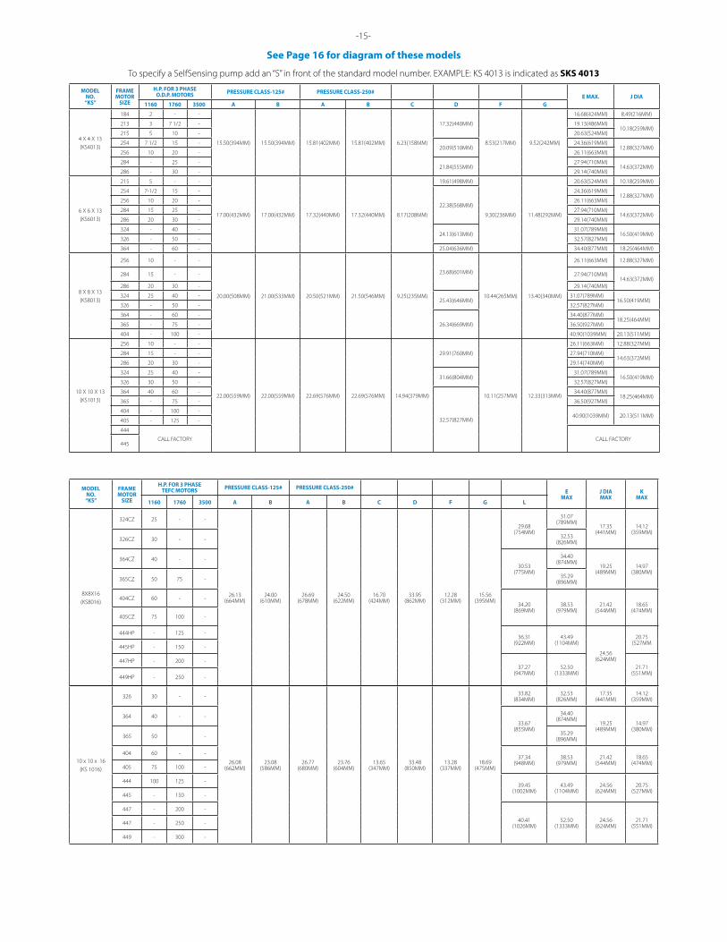
To specify a SelfSensing pump add an “S” in front of the standard model number. EXAMPLE: KS 4013 is indicated as SKS 4013

-16-
This diagram for MOST MODELS (See page 18 for Double Suction Pumps)
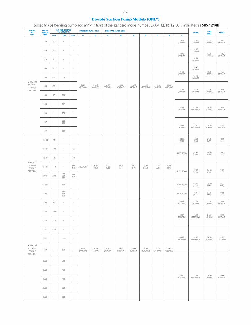
To specify a SelfSensing pump add an “S” in front of the standard model number. EXAMPLE: KS 1213B is indicated as SKS 1214B
-17-
Double Suction Pump Models (ONLY)
MODELNO.“KS”
FRAMEMOTOR
SIZE
H.P. FOR 3 PHASETEFC MOTORS PRESSURE CLASS-125# PRESSURE CLASS-250#
E MAX. J DIAMAX K MAX.
1160 1760 3500 A B A B C D F G L
12 x 12 x 13(KS 1213B)DOUBLESUCTION
286 20 - -
30.25(768MM)
24.25(616MM)
31.00(787MM)
25.00(635MM)
18.87(479MM)
51.26(1302MM)
11.24(285MM)
16.66(423MM)
29.77(756MM)
28.07(729MM)
15.29(388MM)
13.11(333MM)
324 25 - -
30.78(782MM)
31.07(789MM)
17.35(441MM)
14.12(359MM)
326 30 - - 32.53(826MM)
364 40 - -
31.63(803MM)
34.40(874MM)
19.25(489MM)
14.97(380MM)
365 50 75 - 35.29(896MM)
404 60 - -
35.31(897MM)
38.53(979MM)
21.42(544MM)
18.65(474MM)
405 75 100 -
444 - 125 -
37.41(950MM)
43.49(1105MM)
24.56(624MM)
20.75(527MM)
445 - 150 -
447 - 200250 -
38.37(975MM)
52.50(1333MM)
24.56(624MM)
21.71(551MM)
449 - 300 -
12X12X17(KS1217)DOUBLESUCTION
405CZ 75 - -
32.25 (819) 28.25(718)
33.00 (838)
29.00(737)
20.07(510)
53.85(1368)
13.83(351)
19.40(493)
38.05(966)
38.53(979)
21.42(544)
18.65 (474)
444HP 100 - 125
40.15 (1020) 43.49(1105)
24.56 (624)
20.75 (527)
445HP 125 - 150
447HP 150 - 200250
41.11 (1044) 52.50(1333)
24.56(624)
21.71 (551)
449HP 200250300350
300350
G5010 - 400 - 46.40 (1079) 69.75(1772)
29.00(737)
27.00 (686)
G5810 -450500600
- 48.25 (1226) 87.29 (2217)
32.24(819)
28.85 (733)
14 x 14 x 15(KS 1415B)DOUBLESUCTION
405 75 - -
30.38(772MM )
28.38(721MM)
31.12(790MM)
29.12(740MM)
20.88(530MM)
54.31(1379MM)
14.35(364MM)
21.63(550MM)
40.27(1023MM)
38.53(979MM)
21.42(544MM)
18.65(474MM)
444 100 - -
42.37(1076MM)
43.49(1105MM)
24.56(624MM)
20.75(527MM)
445 125 - -
447 150 - -
43.33(1101 MM)
52.50(1333MM)
24.56(624MM)
21.71(551 MM)447 - 250 -
449 - 300 -
48.50(1232MM)
70.02(1779MM)
29.90(760MM)
26.88(683MM)
5000 - 350 -
5000 - 400 -
5000 - 450 -
5000 - 500 -
5000 - 600 -
-18-
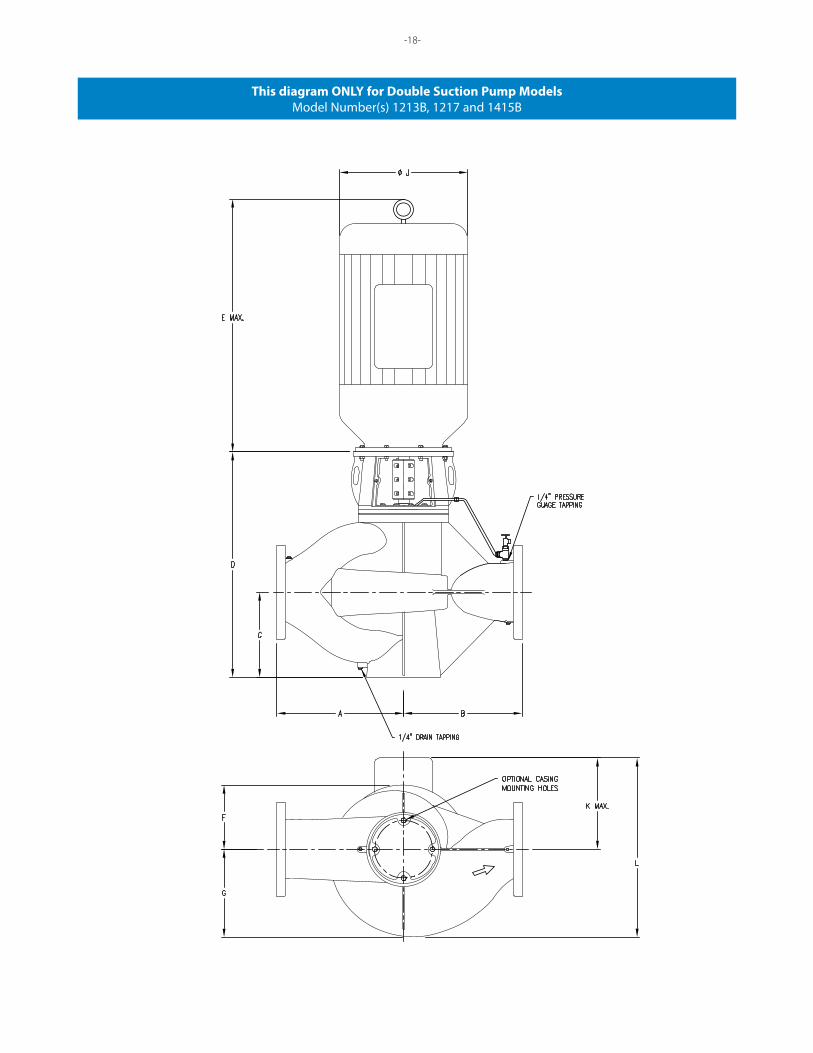
This diagram ONLY for Double Suction Pump ModelsModel Number(s) 1213B, 1217 and 1415B
-17-
Double Suction Pump Models (ONLY)
Taco Inc., 1160 Cranston Street. Cranston, RI 02920 / (401) 942-8000 / Fax (401) 942-2360 Taco (Canada) Ltd., 8450 Lawson Road, Unit #3, Milton, Ontario L9T 0J8 / (905) 564-9422 / Fax (905) 564-9436
www.TacoComfort.com
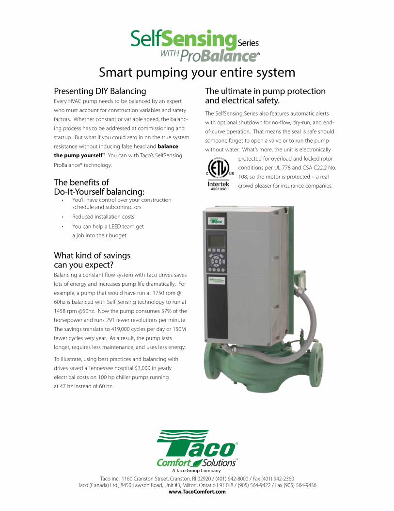
Presenting DIY BalancingEvery HVAC pump needs to be balanced by an expert
who must account for construction variables and safety
factors. Whether constant or variable speed, the balanc-
ing process has to be addressed at commissioning and
startup. But what if you could zero in on the true system
resistance without inducing false head and balance
the pump yourself ? You can with Taco’s SelfSensing
ProBalance® technology.
The benefits of Do-It-Yourself balancing:
• You’ll have control over your construction schedule and subcontractors
• Reduced installation costs
• You can help a LEED team get
a job into their budget
What kind of savings can you expect?Balancing a constant flow system with Taco drives saves
lots of energy and increases pump life dramatically. For
example, a pump that would have run at 1750 rpm @
60hz is balanced with Self-Sensing technology to run at
1458 rpm @50hz. Now the pump consumes 57% of the
horsepower and runs 291 fewer revolutions per minute.
The savings translate to 419,000 cycles per day or 150M
fewer cycles very year. As a result, the pump lasts
longer, requires less maintenance, and uses less energy.
To illustrate, using best practices and balancing with
drives saved a Tennessee hospital $3,000 in yearly
electrical costs on 100 hp chiller pumps running
at 47 hz instead of 60 hz.
The ultimate in pump protection and electrical safety.The SelfSensing Series also features automatic alerts
with optional shutdown for no-flow, dry-run, and end-
of-curve operation. That means the seal is safe should
someone forget to open a valve or to run the pump
without water. What’s more, the unit is electronically
protected for overload and locked rotor
conditions per UL 778 and CSA C22.2 No.
108, so the motor is protected – a real
crowd pleaser for insurance companies.
Smart pumping your entire system