irb40 microscope user’s manual · irb40 microscope user’s manual ... use the ldb color ˜lter...
TRANSCRIPT
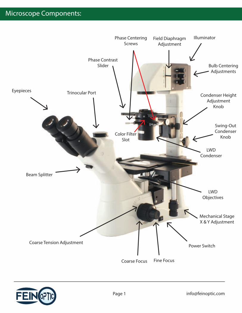
Microscope Components:
Trinocular Port
Phase ContrastSlider
Eyepieces
Illuminator
LWDCondenser
Mechanical StageX & Y Adjustment
Power Switch
Fine FocusCoarse Focus
Coarse Tension Adjustment
Beam Splitter
Condenser HeightAdjustment
Knob
LWDObjectives
Phase CenteringScrews
Color FilterSlot
Field DiaphragmAdjustment
Bulb CenteringAdjustments
Swing-OutCondenser
Knob
Before Use:
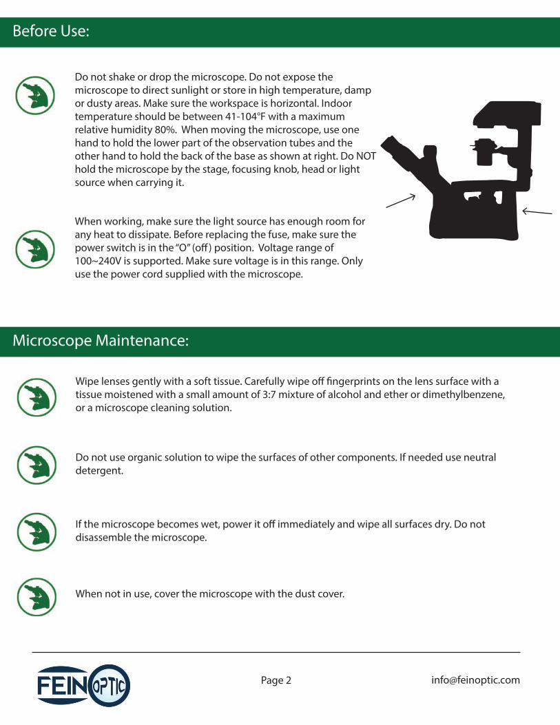
Do not shake or drop the microscope. Do not expose the microscope to direct sunlight or store in high temperature, damp or dusty areas. Make sure the workspace is horizontal. Indoor temperature should be between 41-104°F with a maximum relative humidity 80%. When moving the microscope, use one hand to hold the lower part of the observation tubes and the other hand to hold the back of the base as shown at right. Do NOT hold the microscope by the stage, focusing knob, head or light source when carrying it.
When working, make sure the light source has enough room for any heat to dissipate. Before replacing the fuse, make sure the power switch is in the “O” (o�) position. Voltage range of 100~240V is supported. Make sure voltage is in this range. Only use the power cord supplied with the microscope.
Microscope Maintenance:
Wipe lenses gently with a soft tissue. Carefully wipe o� �ngerprints on the lens surface with a tissue moistened with a small amount of 3:7 mixture of alcohol and ether or dimethylbenzene, or a microscope cleaning solution.
Do not use organic solution to wipe the surfaces of other components. If needed use neutral detergent.
If the microscope becomes wet, power it o� immediately and wipe all surfaces dry. Do not disassemble the microscope.
When not in use, cover the microscope with the dust cover.
Microscope Assembly:
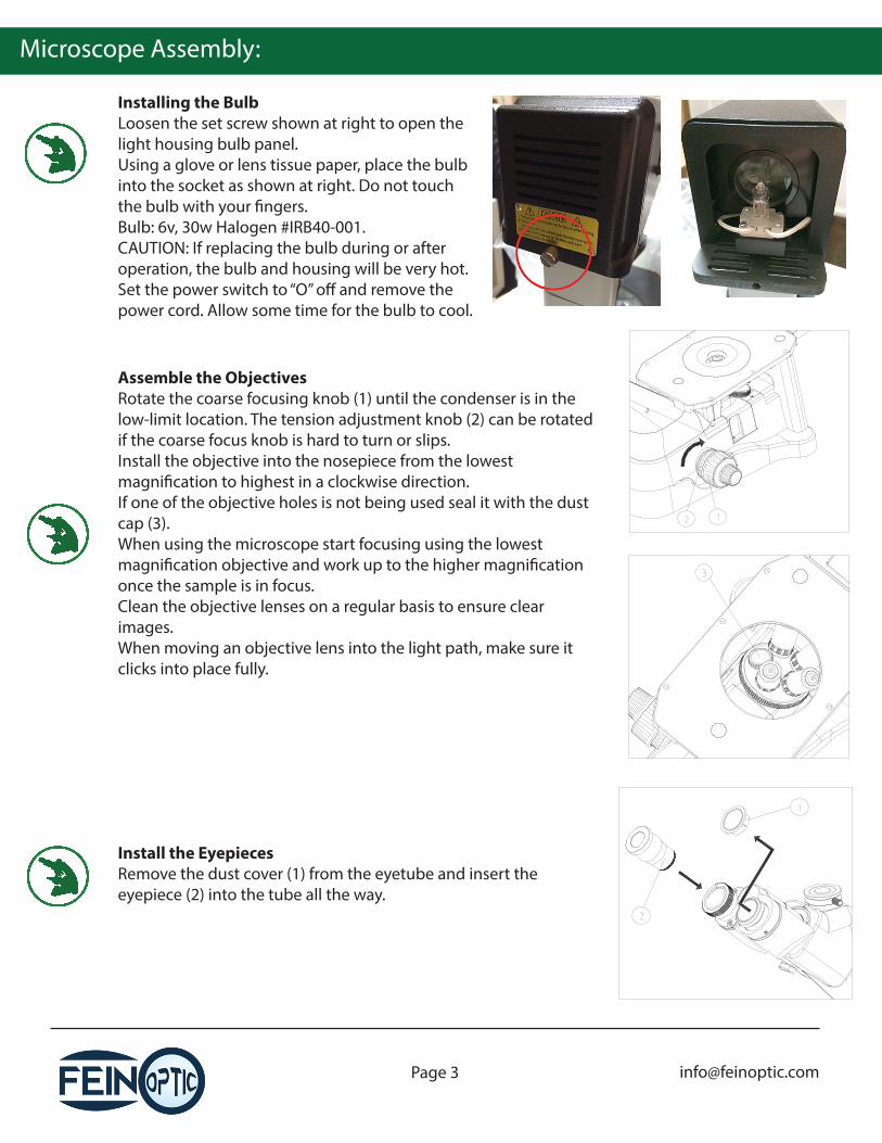
Installing the BulbLoosen the set screw shown at right to open the light housing bulb panel.Using a glove or lens tissue paper, place the bulb into the socket as shown at right. Do not touch the bulb with your �ngers.Bulb: 6v, 30w Halogen #IRB40-001.CAUTION: If replacing the bulb during or after operation, the bulb and housing will be very hot. Set the power switch to “O” o� and remove the power cord. Allow some time for the bulb to cool.
Install the EyepiecesRemove the dust cover (1) from the eyetube and insert the eyepiece (2) into the tube all the way.
Assemble the ObjectivesRotate the coarse focusing knob (1) until the condenser is in the low-limit location. The tension adjustment knob (2) can be rotated if the coarse focus knob is hard to turn or slips.Install the objective into the nosepiece from the lowest magni�cation to highest in a clockwise direction.If one of the objective holes is not being used seal it with the dust cap (3).When using the microscope start focusing using the lowest magni�cation objective and work up to the higher magni�cation once the sample is in focus.Clean the objective lenses on a regular basis to ensure clear images.When moving an objective lens into the light path, make sure it clicks into place fully.
Microscope Assembly:
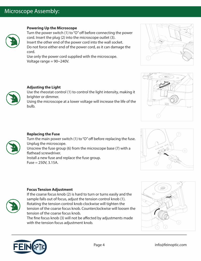
Powering Up the MicroscopeTurn the power switch (1) to “O” o� before connecting the power cord. Insert the plug (2) into the microscope outlet (3).Insert the other end of the power cord into the wall socket.Do not force either end of the power cord, as it can damage the cord.Use only the power cord supplied with the microscope.Voltage range = 90~240V.
Focus Tension AdjustmentIf the coarse focus knob (2) is hard to turn or turns easily and the sample falls out of focus, adjust the tension control knob (1). Rotating the tension control knob clockwise will tighten the tension of the coarse focus knob. Counterclockwise will loosen the tension of the coarse focus knob.The �ne focus knob (3) will not be a�ected by adjustments made with the tension focus adjustment knob.
Adjusting the LightUse the rheostat control (1) to control the light intensity, making it brighter or dimmer.Using the microscope at a lower voltage will increase the life of the bulb.
Replacing the FuseTurn the main power switch (1) to “O” o� before replacing the fuse. Unplug the microscope. Unscrew the fuse group (6) from the microscope base (7) with a �athead screwdriver.Install a new fuse and replace the fuse group.Fuse = 250V, 3.15A.
Microscope Assembly:
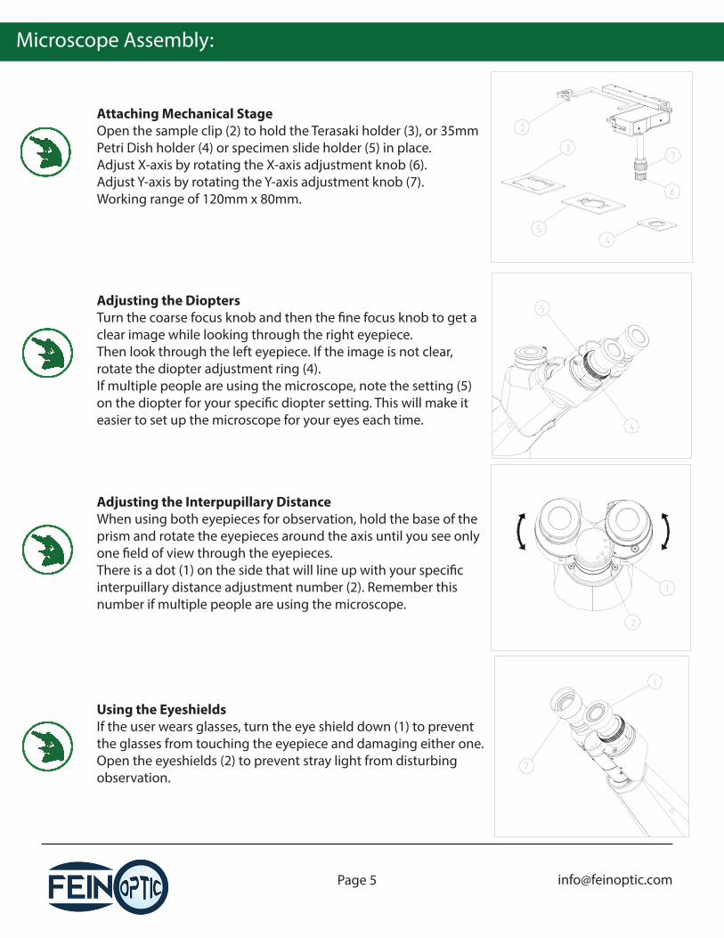
Attaching Mechanical StageOpen the sample clip (2) to hold the Terasaki holder (3), or 35mm Petri Dish holder (4) or specimen slide holder (5) in place.Adjust X-axis by rotating the X-axis adjustment knob (6).Adjust Y-axis by rotating the Y-axis adjustment knob (7).Working range of 120mm x 80mm.
Using the EyeshieldsIf the user wears glasses, turn the eye shield down (1) to prevent the glasses from touching the eyepiece and damaging either one.Open the eyeshields (2) to prevent stray light from disturbing observation.
Adjusting the DioptersTurn the coarse focus knob and then the �ne focus knob to get a clear image while looking through the right eyepiece.Then look through the left eyepiece. If the image is not clear, rotate the diopter adjustment ring (4).If multiple people are using the microscope, note the setting (5) on the diopter for your speci�c diopter setting. This will make it easier to set up the microscope for your eyes each time.
Adjusting the Interpupillary DistanceWhen using both eyepieces for observation, hold the base of the prism and rotate the eyepieces around the axis until you see only one �eld of view through the eyepieces.There is a dot (1) on the side that will line up with your speci�c interpuillary distance adjustment number (2). Remember this number if multiple people are using the microscope.
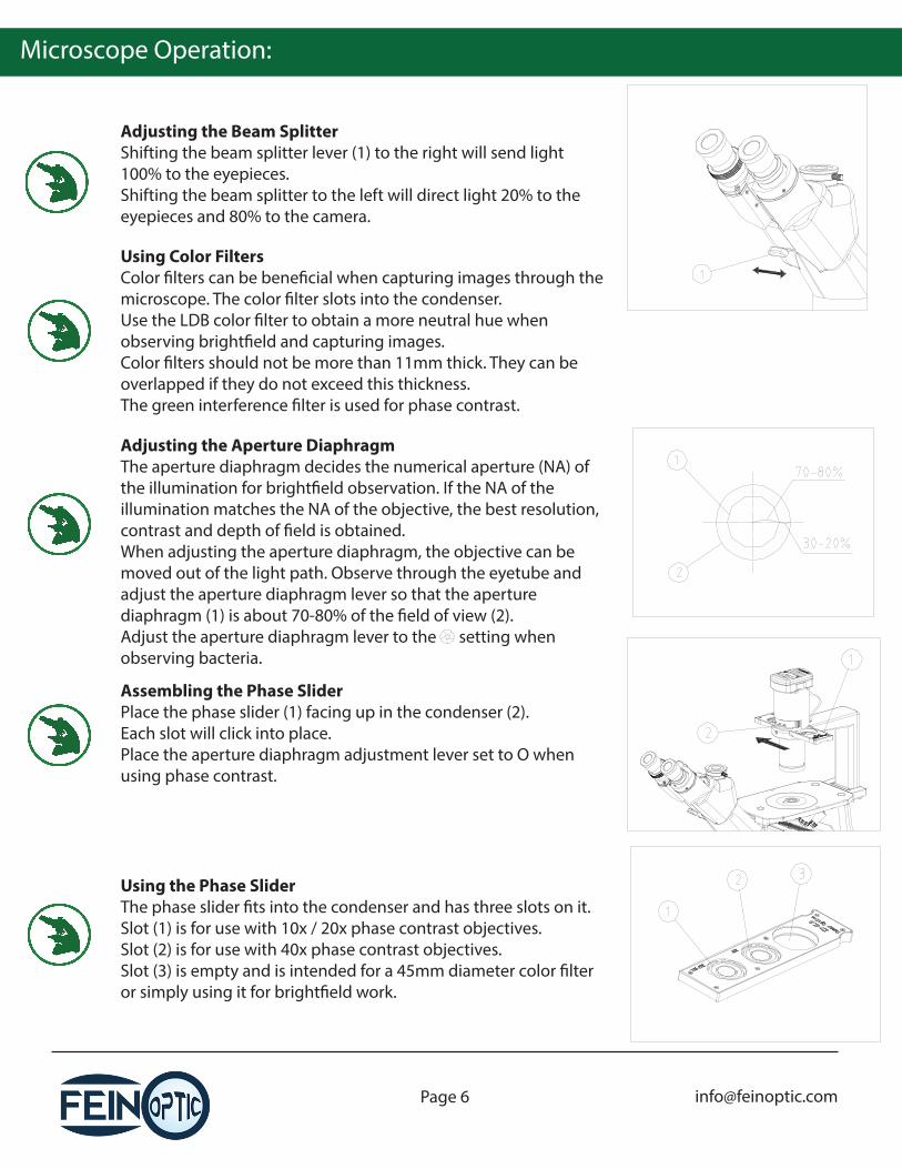
Adjusting the Aperture DiaphragmThe aperture diaphragm decides the numerical aperture (NA) of the illumination for bright�eld observation. If the NA of the illumination matches the NA of the objective, the best resolution, contrast and depth of �eld is obtained.When adjusting the aperture diaphragm, the objective can be moved out of the light path. Observe through the eyetube and adjust the aperture diaphragm lever so that the aperture diaphragm (1) is about 70-80% of the �eld of view (2).Adjust the aperture diaphragm lever to the setting when observing bacteria.
Microscope Operation:
Adjusting the Beam SplitterShifting the beam splitter lever (1) to the right will send light 100% to the eyepieces.Shifting the beam splitter to the left will direct light 20% to the eyepieces and 80% to the camera.
Using the Phase SliderThe phase slider �ts into the condenser and has three slots on it.Slot (1) is for use with 10x / 20x phase contrast objectives.Slot (2) is for use with 40x phase contrast objectives.Slot (3) is empty and is intended for a 45mm diameter color �lter or simply using it for bright�eld work.
Using Color FiltersColor �lters can be bene�cial when capturing images through the microscope. The color �lter slots into the condenser.Use the LDB color �lter to obtain a more neutral hue when observing bright�eld and capturing images.Color �lters should not be more than 11mm thick. They can be overlapped if they do not exceed this thickness.The green interference �lter is used for phase contrast.
Assembling the Phase SliderPlace the phase slider (1) facing up in the condenser (2).Each slot will click into place.Place the aperture diaphragm adjustment lever set to O when using phase contrast.
Microscope Operation:
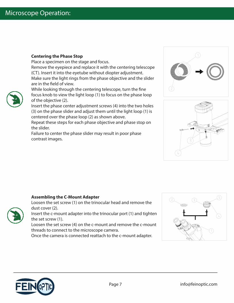
Centering the Phase StopPlace a specimen on the stage and focus.Remove the eyepiece and replace it with the centering telescope (CT). Insert it into the eyetube without diopter adjustment.Make sure the light rings from the phase objective and the slider are in the �eld of view.While looking through the centering telescope, turn the �ne focus knob to view the light loop (1) to focus on the phase loop of the objective (2).Insert the phase center adjustment screws (4) into the two holes (3) on the phase slider and adjust them until the light loop (1) is centered over the phase loop (2) as shown above.Repeat these steps for each phase objective and phase stop on the slider.Failure to center the phase slider may result in poor phase contrast images.
Assembling the C-Mount AdapterLoosen the set screw (1) on the trinocular head and remove the dust cover (2).Insert the c-mount adapter into the trinocular port (1) and tighten the set screw (1).Loosen the set screw (4) on the c-mount and remove the c-mount threads to connect to the microscope camera.Once the camera is connected reattach to the c-mount adapter.
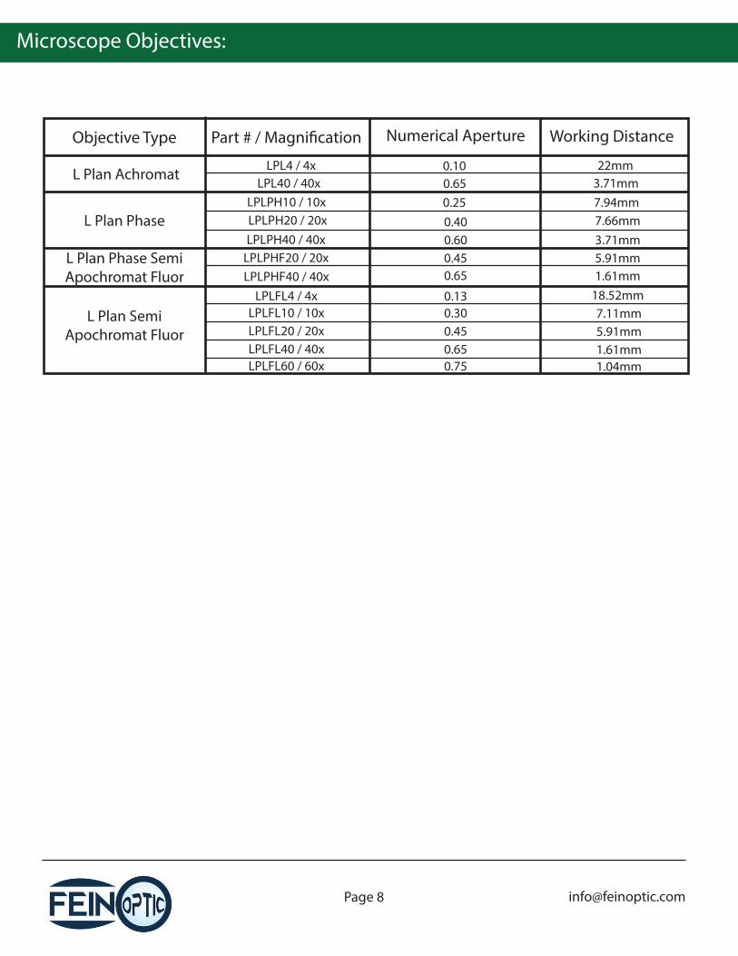
Microscope Objectives:
L Plan Achromat
L Plan Phase
Objective Type Part # / Magni�cation Numerical Aperture Working Distance
LPL4 / 4xLPL40 / 40x
LPLPH10 / 10xLPLPH20 / 20x
0.100.650.250.40
22mm3.71mm7.94mm7.66mm
LPLPHF40 / 40x 0.65
0.130.30
1.61mm18.52mm7.11mm
LPLPH40 / 40x 0.60 3.71mmLPLPHF20 / 20x 0.45 5.91mm
LPLFL4 / 4x
L Plan Phase Semi Apochromat Fluor
L Plan Semi Apochromat Fluor
LPLFL10 / 10x0.45 5.91mm LPLFL20 / 20x0.65 1.61mm LPLFL40 / 40x0.75 1.04mm LPLFL60 / 60x
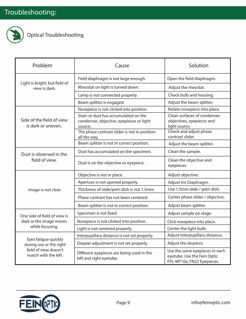
Troubleshooting:
Optical Troubleshooting
Problem Cause Solution
Light is bright, but �eld of view is dark.
Field diaphragm is not large enough.
Rheostat on light is turned down.
Lamp is not connected properly.
Open the �eld diaphragm.
Adjust the rheostat.
Check bulb and housing.
Side of the �eld of view is dark or uneven.
Nosepiece is not clicked into position.Stain or dust has accumulated on the condenser, objective, eyepieces or light source.
Rotate nosepiece into place.Clean surfaces of condenser, objectives, eyepieces and light source.
Dust is observed in the �eld of view.
Dust has accumulated on the specimen.
Dust is on the objective or eyepiece.
Clean the sample.
Clean the objective and eyepieces.
Image is not clear.
Objective is not in place. Adjust objective.
Aperture is not opened properly. Adjust Iris Diaphragm.
Thickness of slide/petri dish is not 1.5mm.
Center phase slider / objective.
Beam splitter is not in correct position. Adjust beam splitter.
One side of �eld of view is dark or the image moves
while focusing.
Specimen is not �xed. Adjust sample on stage.
Nosepiece is not clicked into position. Click nosepiece into place.
Center the light bulb.Light is not centered properly.
Eyes fatigue quickly during use or the right
�eld of view doesn’t match with the left.
Interpupillary distance is not set properly. Adjust interpupillary distance.
Diopter adjustment is not set properly. Adjust the diopters.
Di�erent eyepieces are being used in the left and right eyetube.
Use the same eyepieces in each eyetube. Use the Fein Optic FPL-WF10x, FN22 Eyepieces.
Beam splitter is engaged. Adjust the beam splitter.
The phase contrast slider is not in position all the way.
Check and adjust phase contrast slider.
Beam splitter is not in correct position. Adjust the beam splitter.
Use 1.5mm slide / petri dish.
Phase contrast has not been centered.
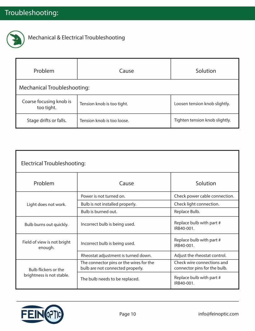
Troubleshooting:
Mechanical & Electrical Troubleshooting
Problem Cause Solution
Stage drifts or falls. Tension knob is too loose. Tighten tension knob slightly.
Power is not turned on. Check power cable connection.
Bulb is not installed properly. Check light connection.
Bulb is burned out. Replace Bulb.
The connector pins or the wires for the bulb are not connected properly.
Check wire connections and connector pins for the bulb.Bulb �ickers or the
brightness is not stable.
Coarse focusing knob is too tight.
Tension knob is too tight. Loosen tension knob slightly.
Light does not work.
Field of view is not bright enough.
Rheostat adjustment is turned down. Adjust the rheostat control.
Bulb burns out quickly. Incorrect bulb is being used. Replace bulb with part # IRB40-001.
Incorrect bulb is being used.
The bulb needs to be replaced.
Mechanical Troubleshooting:
Electrical Troubleshooting:
Replace bulb with part # IRB40-001.
Replace bulb with part # IRB40-001.
Problem Cause Solution