investigation of dyes for dye-sensitized solar cells...
TRANSCRIPT

2
Investigation of Dyes for Dye-Sensitized Solar Cells: Ruthenium-Complex Dyes,
Metal-Free Dyes, Metal-Complex Porphyrin Dyes and Natural Dyes
Seigo Ito Department of Electrical Engineering and Computer Sciences, Graduate School of Engineering, University of Hyogo, Hyogo
Japan
1. Introduction
Following the first report on dye-sensitized solar cells (DSCs) by Prof. Grätzel in 1991, thousands of papers have been published with the aim of making DSCs commercially viable (Fig. 1). They are attractive because of their low-cost materials and convenient fabrication by a non-vacuum, high-speed printing process. One of the key materials in DSCs is the sensitizer dye. Ruthenium-complex dyes are used to make DSCs with conversion efficiencies of over 10%; recently, the Grätzel group reported a DSC using ruthenium dye (Z991) which achieved a conversion efficiency of 12.3%. Research into synthetic ruthenium-free dyes, including metal-free organic dyes and metal-complex porphyrin dyes, has intensified because of the high cost of ruthenium. Indoline dyes and oligothiophene dyes are used to make DSCs with conversion efficiencies greater than 9% and 10%, respectively. A zinc-porphyrin dye produced a conversion efficiency of 11.4%.
Fig. 1. Number of publications on DSCs in each year from 1989 to 2010. The data was obtained by searching online databases (Scopus, Elsevier). The keywords were “dye”, “solar” and “cell”, and the document type was limited to “article”.
www.intechopen.com

Solar Cells – Dye-Sensitized Devices
20
Natural dyes have also been studied for use in DSCs because they are cheaper than synthetic dyes, and exhibit moderate energy conversion efficiency. Natural chlorophyll dyes show energy conversion efficiencies of over 4% and Monascus yellow dye yielded a conversion efficiency of 2.3%. Despite the wide variety of natural dyes available, other natural dyes do not yield energy conversion efficiencies of over 2%, although some natural dyes derivatives are capable of higher energy conversion efficiencies. In this review, the principles and fabrication methods of DSCs are explained, and recent research on sensitizing dyes, including ruthenium-complex dyes, metal-free organic dyes, metal-complex porphyrin dyes, and natural dyes, is reviewed.
2. Ruthenium-complex dyes
Ruthenium dye DSCs were first reported in 1991 by O’Regan and Grätzel in Nature [1]. These first ruthenium dye DSCs achieved a 7.1% conversion efficiency (Fig. 2). However, the structure of the ruthenium dye was complicated and contained three ruthenium metal centers. In 1993, Nazeeruzzin et al. published DSCs with 10.3% conversion [2], using a ruthenium dye sensitizer (N3, Fig. 3: [cis-di(thiocyanato)bis(2,2-bipyridine-4,4-dicarboxylate)ruthenium]]), which contained one ruthenium center and was thus simpler than the ruthenium dye reported in 1991. At the end of the 1990s, Solaronix SA (Switzerland) began selling the materials for constructing DSCs: ruthenium dyes, electrodes, electrolytes, TiO2 paste, fluorine-doped tin oxide (FTO)/glass plates, and sealing materials. This led to a blossoming of DSC research, using the N3 dye (Fig. 3) and nanocrystalline-TiO2 electrodes made using doctor-blading methods, which resulted in the development of sandwich-type solar cells (Fig. 4).
Fig. 2. A ruthenium dye reported in Nature (1991) by Dr. O’Regan and Prof. Grätzel [1].
www.intechopen.com

Investigation of Dyes for Dye-Sensitized Solar Cells: Ruthenium-Complex Dyes, Metal-Free Dyes, Metal-Complex Porphyrin Dyes and Natural Dyes
21
Fig. 3. The ruthenium dye N3, which achieved 10% conversion efficiencies in DSCs, reported by Dr. Nazeeruddin of the Grätzel group [2].
Fig. 4. DSC fabrication methods.
The high performance of the N3 sensitizer adsorbed on to nanocrystalline-TiO2 films (Fig. 5)
brought a significant advance in DSC technology. The sensitizer adsorbed on to the TiO2
surface absorbs a photon to produce an excited state, which efficiently transfers one electron
to the TiO2 conduction band (Fig. 6). The oxidized dye is subsequently reduced by electron
donation from an electrolyte containing the iodide/triiodide redox system. The injected
electron flows through the semiconductor network to arrive at the back contact then
through the external load to the counter electrode, which is made of platinum sputtered
conducting glass. The circuit is completed by the reduction of triiodide at the counter
electrode, which regenerates iodide.
www.intechopen.com

Solar Cells – Dye-Sensitized Devices
22
Fig. 5. Structure and electron movement in DSCs.
Fig. 6. Electron transfer in DSCs.
The high performance achieved by dye-sensitized TiO2 solar cell devices depends on several factors, such as the broad range of visible light absorbed by the dye and the dye’s relatively long-lived excited states with energies near those of the TiO2 conduction band. Moreover, the presence of terminal carboxylic acid groups allows the sensitizer to be stably anchored to the semiconductor surface, ensuring high electronic coupling between the dye and the semiconductor, which is required for efficient charge injection.
www.intechopen.com

Investigation of Dyes for Dye-Sensitized Solar Cells: Ruthenium-Complex Dyes, Metal-Free Dyes, Metal-Complex Porphyrin Dyes and Natural Dyes
23
However, it was difficult to reproduce the 10% efficiency observed in the first published DSCs. In 2001, Nazeeruzzin et al. reported DSCs with 10.4% efficiency using a ruthenium dye called ‘black dye’ in the Journal of the American Chemical Society (Fig. 7) [3]. Although black dye looks green in solvent, on a porous nanocrystalline-TiO2 electrode the DSC looks black, because its wide absorption band covers the entire visible range of wavelengths. The conversion efficiency was confirmed by the National Renewable Energy Laboratory in the United States. Subsequently, using black dye, Wang et al. (AIST, Japan) reported a 10.5% efficiency [4], and Chiba et al. (Sharp Co. Ltd., Japan) reported an 11.1% efficiency, confirmed by AIST [5]. In 2006, Nazeeruzzin et al. reported a new dye, N179, which was similar to N3, but which achieved an 11.2% conversion efficiency in DSCs (Fig. 8) [6]. N3 has four H+ counterions, whereas N719 has three TBA+ and one H+ counterions (Fig. 9). The change in the counterions alters the speed of adsorption onto the porous TiO2 electrode; N3 is fast (3 h) whereas N719 is slow (24 h), thus N719 gives a higher conversion efficiency than N3.
Fig. 7. Structure of black dye for DSCs [3]. TBA+: tetrabutylammonium.
Fig. 8. Photo I-V curve for DSC with 11.1% conversion efficiency, using N719 [6].
www.intechopen.com

Solar Cells – Dye-Sensitized Devices
24
Fig. 9. A ruthenium dye (N719) for DSCs [6]. TBA+: tetrabutylammonium.
In 2008, Ito et al. detailed DSC fabrication methods [7] that improved the reproducibility of
the results for DSC conversion efficiencies (Fig. 10), and many papers have subsequently
reported conversion efficiencies close to 10%. The components of high efficiency DSCs, such
as the TiCl4-treated photoelectrodes, the thickness of the transparent nanocrystalline-TiO2-
layer, the light-scattering layer (Fig. 11), and the anti-reflective film on transparent
conducting oxide (TCO) substrates, have been optimized. These components have a
significant effect on the conversion efficiency. TiCl4 treatment is necessary for improving the
mechanical strength of the TiO2 layer. The thickness of the TiO2 layer affects the
photocurrent and the photovoltage of the devices. Furthermore, the photocurrent can also
be increased by using an anti-reflective film. The combination of both transparent and light-
scattering layers in a double layer system (Fig. 12) and an anti-reflective film creates a
photon-trapping effect, which has been used to enhance the quantum efficiency, known as
the incident photon-to-electricity conversion efficiency (IPCE).
Fig. 10. Histogram showing the reproducibility of DSC conversion efficiencies. Reported values for 12 DSC devices produced over a 24 h period. [7].
www.intechopen.com

Investigation of Dyes for Dye-Sensitized Solar Cells: Ruthenium-Complex Dyes, Metal-Free Dyes, Metal-Complex Porphyrin Dyes and Natural Dyes
25
In this section, the fabrication method and the influence of different procedures on the photovoltaic performance of high-efficiency DSCs is described [7]. Two types of TiO2 paste containing nanocrystalline-TiO2 (20 nm) and macrocrystalline-TiO2 (400 nm) particles (Fig. 11) were prepared, which gave transparent and light-scattering layers, respectively (Fig. 12) [8]. The synthesis of cis-di(thiocyanato)-N,N'-bis(2,2'-bipyridyl-4-carboxylic acid-4'-tetrabutylammoniumcarboxylate)ruthenium(II) (N-719, Fig. 9) has previously been reported [6]. The purification of N-719 was carried out by repeating the following method three times. The N719 complex was dissolved in water containing 2 equiv of tetrabutylammonium hydroxide. The concentrated solution was filtered through a sintered glass crucible, applied to a water-equilibrated Sephadex LH-20 column, and then the adsorbed complex was eluted using water. The main band was collected and the pH of the solution was lowered to 4.3 using 0.02 M HNO3. The titration was carried out slowly over a period of 3 h and then the solution was kept at –20 °C for 15 h. After allowing the flask to warm to 25 °C, the precipitated complex was collected on a glass frit and air-dried.
(a)
(b)
Fig. 11. SEM images of the surface of TiO2 submicrometer particles (400C, JGC-CCIC) (upper) and a mixture of TiO2 submicrometer particles and nanoparticles (PST-400C, JGC-
CCIC) (lower). Images were acquired at 50,000 magnification [8].
www.intechopen.com
Solar Cells – Dye-Sensitized Devices
26
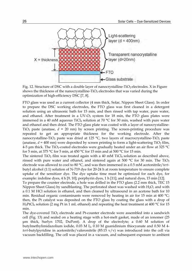
Fig. 12. Structure of DSC with a double layer of nanocrystalline-TiO2 electrodes. X in Figure shows the thickness of the nanocrystalline-TiO2 electrodes that was varied during the optimization of high-efficiency DSC [7, 8].
FTO glass was used as a current collector (4 mm thick, Solar, Nippon Sheet Glass). In order to prepare the DSC working electrodes, the FTO glass was first cleaned in a detergent solution using an ultrasonic bath for 15 min, and then rinsed with tap water, pure water, and ethanol. After treatment in a UV-O3 system for 18 min, the FTO glass plates were immersed in a 40 mM aqueous TiCl4 solution at 70 °C for 30 min, washed with pure water and ethanol and then dried. The FTO glass plate was coated with a layer of nanocrystalline-TiO2 paste (anatase, d = 20 nm) by screen printing. The screen-printing procedure was repeated to get an appropriate thickness for the working electrode. After the nanocrystalline-TiO2 paste was dried at 125 °C, two layers of macrocrystalline-TiO2 paste (anatase, d = 400 nm) were deposited by screen printing to form a light-scattering TiO2 film, 4-5 μm thick. The TiO2-coated electrodes were gradually heated under an air flow at 325 °C for 5 min, at 375 °C for 5 min, at 450 °C for 15 min and at 500 °C for 15 min. The sintered TiO2 film was treated again with a 40 mM TiCl4 solution as described above, rinsed with pure water and ethanol, and sintered again at 500 °C for 30 min. The TiO2 electrode was allowed to cool to 80 °C, and was then immersed in a 0.5 mM acetonitrile/tert-butyl alcohol (1:1) solution of N-719 dye for 20-24 h at room temperature to ensure complete uptake of the sensitizer dye. The dye uptake time must be optimized for each dye, for example: indoline dyes, 4 h [9, 10]; porphyrin dyes, 1 h [11]; and natural dyes, 15 min [12]. To prepare the counter electrode, a hole was drilled in the FTO glass (2.2 mm thick, TEC 15 Nippon Sheet Glass) by sandblasting. The perforated sheet was washed with H2O, and with a 0.1 M HCl solution in ethanol, and then cleaned by ultrasound in an acetone bath for 10 min. Residual organic contaminants were removed by heating in air for 15 min at 400 °C; then, the Pt catalyst was deposited on the FTO glass by coating the glass with a drop of H2PtCl6 solution (2 mg Pt in 1 mL ethanol) and repeating the heat treatment at 400 °C for 15 min. The dye-covered TiO2 electrode and Pt-counter electrode were assembled into a sandwich cell (Fig. 13) and sealed on a heating stage with a hot-melt gasket, made of an ionomer (25 μm thick, Surlyn 1702, DuPont). A drop of the electrolyte; a 0.60 M solution of butylmethylimidazolium iodide, 0.03 M I2, 0.10 M guanidinium thiocyanate and 0.50 M 4-tert-butylpyridine in acetonitrile/valeronitrile (85:15 v/v) was introduced into the cell via vacuum backfilling. The cell was placed in a vacuum, and subsequent exposure to ambient
www.intechopen.com

Investigation of Dyes for Dye-Sensitized Solar Cells: Ruthenium-Complex Dyes, Metal-Free Dyes, Metal-Complex Porphyrin Dyes and Natural Dyes
27
pressure pushed the electrolyte into the cell. Finally, the hole was covered by a hot-melt ionomer film (35 μm thick, Bynel 4164, Du-Pont) and a cover glass (0.1 mm thick), and sealed with a hot soldering iron. The electrolyte must be optimized for each dye: black dye is used with 0.6 M dimethyl
propyl imidazolium iodide, 0.1 M lithium iodide, 0.05 M iodine, and 0.5 M tert-
butylpryidine in acetone [5]; D149, D205, and Monascus yellow (a natural dye) are used
with 0.10 M lithium iodide, 0.60 M butylmethylimidazolium iodide, 0.05 M I2, and 0.05 M 4-
tert-butylpyridine in acetonitrile/valeronitrile (85:15) [9, 10, 12]; YD-2 (a porphyrin dye) is
used with 1.0 M 1,3-dimethylimidazolium iodide, 0.03 M iodine, 0.5 M tert-butylpyridine,
0.05 M LiI, 0.1 M guanidinium thiocyanate, in acetonitrile/valeronitrile (85:15 v/v) [13].
Photovoltaic measurements were taken using an AM 1.5 solar simulator (100 mW cm-2). The
power of the simulated light was calibrated using a reference Si photodiode equipped with
an infrared (IR) cut-off filter in order to reduce the mismatch between the simulated light
and the AM 1.5 spectrum in the 350-750 nm region to less than 2% [14]. The current-voltage
(I-V) curves were obtained by applying an external bias to the cell and measuring the
photocurrent with a digital source meter.
Fig. 13. Structure of DSCs.
In order to demonstrate the effect of the sensitizing dye on the photovoltaic performance, two types of TiO2 working electrode were prepared on the FTO/glass substrate (Fig. 14)
www.intechopen.com

Solar Cells – Dye-Sensitized Devices
28
[15]. The first type of working electrode, nano-TiO2, is a double layer of mesoporous TiO2 (TiO2 nanoparticles d = 20 nm; nanocrystalline TiO2 layer, 14 μm; microcrystalline TiO2 layer, 4 μm) screen-printed onto the FTO. The second type of electrode, UL/nano-TiO2, used a compact TiO2 underlayer (UL) deposited by spray pyrolysis between the porous TiO2 layer and the FTO. Figure 14 shows the dark I-V characteristics of the two types of mesoscopic-TiO2 electrodes, with and without ruthenium dye. The onset of the dark current in the nano-TiO2 electrode occurred at a low forward bias. The compact TiO2 UL suppresses the dark current, shifting its onset by several hundred millivolts. This indicates that the triiodide reduction in the exposed part of the FTO layer is responsible for the high dark current observed in the nanocrystalline TiO2 film alone. Adsorption of the N-719 dye onto the nano-TiO2 electrode also suppresses the dark current (Fig. 15), indicating that the ruthenium sensitizer itself worked as an effective blocking layer on the FTO layer. In contrast, the dark-current curves of UL/nano-TiO2 were shifted to slightly lower voltages by the adsorption of the N-719 dye (Fig. 15) indicating that the sensitizer increases the dark current on electrodes where the FTO surface is already blocked. This can be attributed to the TiO2 band shifting to positive values by surface protonation; the protons can be supplied by the ruthenium dye. The photovoltaic results are shown in Figure 16 and confirm the trends observed in the dark currents. The dye loaded nanocrystalline TiO2 film alone gave a lower conversion efficiency (Fig. 16, nano-TiO2/Ru-dye). Introducing the compact TiO2 UL in the nano-TiO2/Ru-dye electrode increased the open-circuit photovoltage (VOC) by 27 mV and the short-circuit photocurrent density (JSC) by 1 mA cm-2. The difference between the nano-TiO2/Ru-dye and UL/nano-TiO2/Ru-dye electrodes arose from the UL suppressing the charge recombination at the FTO layer. Mathematical modeling of charge-recombination carried out by Ferber et al. (Fig. 17) [16] shows good agreement with these I-V curves. Therefore, the observed improvement of the VOC and JSC from using a UL on the FTO layer agrees with the theoretical calculations. The suppression of dark current is enhanced by introducing a compact layer between the FTO and the TiO2 nanocrystals, and leads to an increase in the VOC. However, the performance of DSCs with spray-pyrolyzed TiO2 ULs is less reproducible; to avoid this problem, TiCl4 treatment between the FTO and nanocrystalline-TiO2 layers is used instead (Fig. 10) [7].
Fig. 14. Two types of TiO2 working electrodes demonstrating the effect of the sensitizing dye on the photovoltaic results: (a) nano-TiO2 and (b) UL/nano-TiO2 [15].
www.intechopen.com

Investigation of Dyes for Dye-Sensitized Solar Cells: Ruthenium-Complex Dyes, Metal-Free Dyes, Metal-Complex Porphyrin Dyes and Natural Dyes
29
Fig. 15. Dark current-voltage characteristics of the mesoscopic TiO2 electrodes shown in Fig. 14 in sandwich cells, with and without adsorbed ruthenium dye. The counter electrode was Pt-coated FTO [15].
Fig. 16. Photovoltage-current curves for DSCs with two types of electrodes (shown in Fig. 14) under a solar simulator (AM 1.5, 100 mW cm-2) [15].
www.intechopen.com

Solar Cells – Dye-Sensitized Devices
30
Fig. 17. The effect of the electron recapture rate constant ke on the I-V curve of the modeled DSC. Base case parameters [16].
It was found that the VOC was shifted by modifying the number of protons in the ruthenium dye (Fig. 18) [17]. When dyes that contain protonated carboxylic groups are adsorbed, the anchoring groups transfer most of their protons to the TiO2 surface, and the positive charge of the surface shifts the Fermi level in a positive direction. The electric field, which is associated with the surface dipole generated by the positive charge, enhances the dye adsorption and assists electron injection from the sensitizer’s excited state into the TiO2 conduction band, thus increasing photocurrents. However, the positive shift in the Fermi level decreases the gap between the iodide/triiodide redox couple and the Fermi level, resulting in a lower open-circuit potential. In contrast, adsorption of a sensitizer that contains no protons shifts the Fermi level in a negative direction, leading to a higher value for the open-circuit potential, while the value of the short circuit current is low. Therefore, there is an optimum degree of protonation for the sensitizer, where the product of the short circuit photocurrent and the open circuit potential is high, thus maximizing the power conversion efficiency of the cell. Varying the degree of protonation of the sensitizer, however, also changes its electronic structure; therefore it is important to investigate how the energy and composition of the excited states change as a function of the protonation of the terminal carboxylic acid groups. In order to enhance the photocurrent of DSCs, the mesoscopic surface area of the nanocrystalline-TiO2 photoelectrode has been improved by chemical bath deposition of TiO2 from TiCl4 (Fig. 19) [7]. BET measurements confirmed that the surface area was increased by 20%. Moreover, a photon-trapping system has been applied to porous TiO2 electrodes using double-layer system consisting of transparent and light-scattering layers (Fig. 12) [7, 8]. Figure 20 shows the photovoltaic characteristics of the DSC were improved by the TiCl4 treatment and the double layer system (JSC = 18.2 mA cm-2, VOC = 789 mV, FF = 0.704, and η = 10.1%). It has previously been reported that the light-scattering layer is important not only for the photon-trapping system, but also for photovoltaic generation. DSCs with the dye-sensitized light-scattering-TiO2 layer, but without the transparent nanocrystalline-TiO2 layer, gave a conversion efficiency of 5% [18].
www.intechopen.com

Investigation of Dyes for Dye-Sensitized Solar Cells: Ruthenium-Complex Dyes, Metal-Free Dyes, Metal-Complex Porphyrin Dyes and Natural Dyes
31
(a)
(b)
Fig. 18. (a) Structures of ruthenium dyes, and (b) the effect of dye protonation on photocurrent-voltage characteristics of nanocrystalline TiO2 cell sensitized with N3 (4 protons), N719 (2 protons), N3[TBA]3 (1 proton), and N712 (0 protons) dyes, measured under AM 1.5 sun using 1 cm2 TiO2 electrodes with an I-/I3- redox couple in methoxyacetonitrile [17].
www.intechopen.com

Solar Cells – Dye-Sensitized Devices
32
Fig. 19. Effect of the TiCl4 treatment. An additional TiO2 layer (1 nm thick) was coated on the surface of the nanocrystalline TiO2 porous film [7].
Fig. 20. Differences in the I-V curves from standard TiO2 electrodes, electrodes with no TiCl4 treatment and electrodes with no light-scattering layer. The transparent and light-scattering layers were 14 μm and 5 μm thick, respectively. Photovoltaic characteristics: standard TiO2 electrode, JSC = 18.2 mA cm-2, VOC = 789 mV, FF = 0.704 and η = 10.1%; without TiCl4, JSC = 16.6 mA cm-2, VOC = 778 mV, FF = 0.731 and η = 9.40%; without light-scattering layer, JSC = 15.6 mA cm-2, VOC = 791 mV, FF = 0.740 and η = 9.12% [7].
Photoconversion happens on the surface of the dye-covered TiO2 layer and the surface area can be calculated from the thickness of the porous layer. Therefore, in order to optimize the photovoltaic performance of DSCs, it is important to understand the relationship between the thickness of the nanocrystalline-TiO2 layer and the conversion efficiency of the DSC (Fig. 21) [7, 11]. A thickness of around 14 μm was confirmed as the optimum for DSCs using N719 dye. Hence, the total optimum thickness of the TiO2 layer, consisting of the transparent layer (14 μm) and the light-scattering layer (5 μm), was around 19 μm for N719.
www.intechopen.com

Investigation of Dyes for Dye-Sensitized Solar Cells: Ruthenium-Complex Dyes, Metal-Free Dyes, Metal-Complex Porphyrin Dyes and Natural Dyes
33
However, a total thickness of 32 μm was necessary for DSCs using black dye, because it has a lower photo-absorbance coefficient than N719 [4].
Fig. 21. Relationship between the thickness of the transparent nanocrystalline-TiO2 layer (in Fig. 12) and the conversion efficiency of DSCs with anti-reflective films. Each point is the average of four cells [7].
Because glass substrates reflect 8-10% of the incident light, an anti-reflective film is necessary to enhance the photovoltaic performance of DSCs. The light-reflecting losses were eliminated by a self-adhesive fluorinated polymer film (Arktop, Asahi Glass) that also served as a 380 nm UV cut-off filter. Masks made of black plastic tape were attached to the Arktop filter to reduce scattered light. Figure 22 shows the IPCE of an electrode with anti-reflective film compared to the electrode without. The anti-reflective film enhances the IPCE from 87% to 94%, increasing the conversion efficiency by 5%.
Fig. 22. Effect of anti-reflective film (Arktop) on the IPCE of DSC. A double-layer electrode (14 μm thick transparent and 5 μm light-scattering TiO2 layers) was used.[7].
www.intechopen.com

Solar Cells – Dye-Sensitized Devices
34
Optimizing the thickness of the nanocrystalline-TiO2 layer, TiCl4 treatments, and the anti-reflective film have allowed DSCs with conversion efficiencies of over 10% to be fabricated. Figure 10 shows the photoconversion efficiency of DSCs made at the same time; among the 12 devices, the reproducibility of DSCs with a conversion efficiency of over 10% was 100%. The error in the experimental results falls within the measurement error for a solar simulator, and therefore conversion efficiencies of 10.2 ± 0.2% is highly reproducible. Using the above technique, DSCs with efficiencies of 11.3% [19] and 12.3% [20] containing the dyes C101 (Fig. 23) and Z991 (Fig. 24), respectively, have recently been published by the Grätzel group, which are the highest conversion efficiencies published to date.
Fig. 23. The structure of the ruthenium dye C101, which achieved an 11.3% conversion efficiency in DSCs [19].
Fig. 24. The structure of the ruthenium dye Z991 which achieved a conversion efficiency of 12.3% in DSCs [20].
www.intechopen.com

Investigation of Dyes for Dye-Sensitized Solar Cells: Ruthenium-Complex Dyes, Metal-Free Dyes, Metal-Complex Porphyrin Dyes and Natural Dyes
35
3. Metal-free dyes
Ruthenium complex dyes are capable of delivering DSCs with high photoenergy-conversion
efficiencies. However, because ruthenium is a rare and expensive metal ruthenium dyes are
not suitable for cost-effective, environmentally friendly photovoltaic systems. This limits the
range of applications for these complexes, and makes the development of DSCs that use
metal-free, organic dyes essential for their practical use. Recently, numerous organic dyes
for high-efficiency DSCs have been reported. New organic dyes with efficiencies over 5%
include hemicyanine dye (Fig. 25) (η = 5.1%) [21], polyene-diphenylaniline dye (Fig. 26) (η =
5.1%) [22], thienylfluorene dye (Fig. 27) (η = 5.23%) [23], phenothiazine dye (Fig. 28) (η =
5.5%) [24], thienothiophene-thiophene-derived dye (Fig. 29) (η = 6.23%) [25], phenyl-
conjugated polyene dye (η = 6.6%) (Fig. 30) [26], N,N-dimethylaniline-cyanoacetic acid (Fig.
31) (η = 6.8%) [27, 28], oligothiophene dye (Fig. 32) (η = 7.7%) [29], coumarin dye (Fig. 33) (η
= 8.2%) [30], indoline dye (Fig. 34) (η = 9.03%) [9, 31] and oligo-phenylenevinylene-unit dye
(Fig. 35) (η = 9.1%) [32].
Fig. 25. Hemicyanine dye [21].
Fig. 26. Polyene-diphenylaniline dye [22].
Fig. 27. Thienylfluorene dye [23].
www.intechopen.com

Solar Cells – Dye-Sensitized Devices
36
Fig. 28. Phenothiazine dye [24].
Fig. 29. Thienothiophene-thiophene-derived dye [25].
Fig. 30. Phenyl-conjugated polyene dye [26].
Fig. 31. N,N-dimethylaniline-cyanoacetic acid [27, 28].
www.intechopen.com

Investigation of Dyes for Dye-Sensitized Solar Cells: Ruthenium-Complex Dyes, Metal-Free Dyes, Metal-Complex Porphyrin Dyes and Natural Dyes
37
Fig. 32. Oligothiophene dye [29].
Fig. 33. Coumarin dye [30],
Fig. 34. Indoline dye (D149) [31].
www.intechopen.com

Solar Cells – Dye-Sensitized Devices
38
Fig. 35. Oligo-phenylenevinylene-unit dye [32].
In order to improve the conversion efficiency values, the structure of organic dye photosensitizers needed to be altered. For example, controlling the aggregation of dye molecules improves the photocurrent generation; π-stacked aggregation (D and H aggregation) on the nanocrystalline-TiO2 electrodes should normally be avoided. Aggregation may lead to intermolecular quenching and the presence of molecules that are not functionally attached to the TiO2 surface which act as filters. Some ruthenium complexes (black dye and N719) have shown their best results using chenodeoxycholic acid (CDCA), which functions as an anti-aggregation reagent and improves the photovoltaic effect. However, indoline dyes and coumarin dyes form photoactive aggregates on nanocrystalline-TiO2 electrodes for DSCs, in a process known as J-aggregation. In order to control the aggregation between dye molecules, an indoline dye with an n-octyl substituent on the rhodanine ring of D149 (Fig. 34) was synthesized, to give dye D205 (Fig. 36) [33]. Figure 37 shows the photovoltaic characteristics of DSCs using D149 and D205. Table 1 shows that n-octyl substitution increased the VOC regardless of whether CDCA was present. CDCA increased the VOC of D205 by approximately 0.054 V, but had little effect on D149, which only showed an increase of 0.006 V. The combination of CDCA and the n-octyl chain (D205) significantly improved the VOC by up to 0.710 V, which is 0.066 V higher (by 10.2%) than that of D149 with CDCA. Kroeze et al. [34] showed that the alkyl substitution of dyes improved the VOC, because of the blocking effect on the charge recombination between triiodide and electrons injected in the nanocrystalline-TiO2 electrodes. Therefore, the VOC variation observed in Figure 37 indicates that the charge recombination was impeded by the blocking effect, arising from the combination of the n-octyl chain and CDCA.
Fig. 36. Indoline dye (D205) [33].
www.intechopen.com

Investigation of Dyes for Dye-Sensitized Solar Cells: Ruthenium-Complex Dyes, Metal-Free Dyes, Metal-Complex Porphyrin Dyes and Natural Dyes
39
Fig. 37. Photovoltaic characteristics of DSCs using D149 and D205 with or without CDCA [33].
Photovoltaic parameter
Without CDCA With CDCA
D149 D205 D149 D205
Jsc / mA cm-2 19.08±0.26 18.99±0.19 19.86±0.10 18.68±0.08
Voc / V 0.638±0.05 0.656±0.11 0.644±0.13 0.710±0.07
FF 0.682±0.06 0.678±0.09 0.694±0.06 0.707±0.09
η / % 8.26±0.09 8.43±0.16 8.85±0.18 9.40±0.12
Table 1. Photovoltaic characteristics of DSCs with indoline dyes shown in Figure 34 and 36. Each result was obtained from three DSCs [33].
Without CDCA, the variation in JSC arising from n-octyl substitution on the rhodanine ring
was small (0.5% of JSC). However, in the presence of CDCA, the effect of the n-octyl chain
was significant; the substitution of the n-octyl chain (from D149 to D205) with CDCA
decreased JSC by 5.9%. The effect of n-octyl substitution and CDCA on the FF was similarly
small; without CDCA, the n-octyl substitution decreased the FF by 0.6%, and with CDCA,
the n-octyl substitution increased the FF by 1.9%.
Without CDCA, the increase in conversion efficiency from D149 to D205 was only by 2.1%, and in the presence of CDCA, the increase was by 6.2%. The resulting average conversion efficiency for D205 with CDCA was an outstanding 9.40% (Table 2). The highest conversion efficiency value of 9.52% was achieved with a DSC based on D205 (JSC: 18.56 mA cm-2, VOC: 0.717 V, and FF: 0.716). Reproducible efficiencies from 9.3% to 9.5% were obtained with the D205 solar cell. Recently, the group of Prof. Peng Wang has reported the synthesis of organic dyes with conversion efficiencies in DSCs that rival those of ruthenium dyes; the highest value for a
www.intechopen.com

Solar Cells – Dye-Sensitized Devices
40
ruthenium dye is 12.3%, under the same measurement conditions [20]. Dye C217 (Figure 38) produced DSCs with 9.8% conversion efficiency, [35] and dye C219 (Figure 39) achieved a 10.1% conversion efficiency [36]. These results strongly suggest that utilizing organic dye photosensitizers is a promising approach for producing high-performance, low cost, recyclable DSCs.
Fig. 38. C217 dye [35].
Fig. 39. C219 dye [36].
4. Metal-complex porphyrin dye
A further strategy for avoiding the use of expensive ruthenium in DSC dyes is to use
complexes containing inexpensive metals. Large π-aromatic molecules, such as porphyrins
and phthalocyanines, are attractive potential candidates for thin, low-cost, efficient DSCs,
because of their photostability and high light-harvesting capability. Porphyrins show strong
absorption and emission in the visible region, as well as tunable redox potentials. These
www.intechopen.com

Investigation of Dyes for Dye-Sensitized Solar Cells: Ruthenium-Complex Dyes, Metal-Free Dyes, Metal-Complex Porphyrin Dyes and Natural Dyes
41
properties mean they have many potential applications, in areas such as optoelectronics,
catalysis, and chemosensing. Self-assembled porphyrin molecular structures play a key role
in solar energy research, because the photosynthetic systems of bacteria and plants contain
chromophores based on porphyrins, which efficiently collect and convert solar energy into
chemical energy. Various artificial photosynthetic model systems have been designed and
synthesized in order to elucidate the factors that control the photoinduced electron-transfer
reaction. Inspired by efficient energy transfer in naturally occurring photosynthetic reaction
centers, numerous porphyrins and phthalocyanines have been synthesized and tested in
DSCs. Campbell et al. have reported zinc porphyrin dyes (Fig. 40) which have conversion efficiencies of 7.1% [37]. A recently reported series of zinc porphyrin dyes with donor–acceptor (D–A) substituents exhibit promising photovoltaic properties with a conversion efficiency of 6.8% (YD-2, Fig. 41) [38]. Bessho et al. optimized the fabrication method for YD-2-sensitized DSCs, resulting in the achievement of an 11% solar-to-electric power conversion efficiency under standard conditions (AM 1.5G, 100 mW cm-2 intensity) (Fig. 42) [13], which is the highest conversion efficiency for a DSC using a ruthenium-free dye so far.
Fig. 40. Zinc porphyrin dyes by synthesized by Campbell et al. [37]
Fig. 41. Structure of porphyrin dye YD-2 [38].
www.intechopen.com

Solar Cells – Dye-Sensitized Devices
42
Fig. 42. Photocurrent density–voltage (J–V) characteristics of a device using YD-2 as sensitizer under AM 1.5G illumination (100 mWcm2). Values for dark current (solid line) and 100% sun (dotted line) are shown [13].
5. Natural dyes
Although high performance synthetic ruthenium-free dyes have been developed, their synthesis is time-consuming and laborious. Furthermore, they must be tested for toxicity before they can be used commercially. These problems could be solved if inexpensive, non-toxic, natural dyes, such as pigments used in food coloring, could be used in DSCs. Natural dyes are easily and safely extracted from plants, which means they are cheap and widely available, and do not require complex synthesis or toxicity testing. Therefore, the use of natural dyes is important for the development of cheap, commercially available DSCs. Natural dyes have shown moderate energy conversion efficiencies in DSCs [39-45]; natural chlorophyll dyes achieved energy conversion efficiencies of over 4% (Fig. 43) [39, 40]. However, despite the huge range of natural dyes, most of the other dyes tested yielded energy conversion efficiencies below 2%, although some derivatives synthesized from natural dyes have produced energy conversion efficiencies of over 2% [46, 47]).
Fig. 43. Structures of chlorophylls for DSCs: Chlorin e6 (left) [39] and chlorophyll c (right) [40].
www.intechopen.com

Investigation of Dyes for Dye-Sensitized Solar Cells: Ruthenium-Complex Dyes, Metal-Free Dyes, Metal-Complex Porphyrin Dyes and Natural Dyes
43
The natural dye Monascus yellow produces DSCs with over 2% conversion efficiency [12]. It
is extracted from Monascus (red yeast rice), which is the product of Monascus purpureus
fermentations. Monascus is a dietary staple in some Asian countries, and is traditionally
made by inoculating rice soaked in water with Monascus purpureus spores. The mixture is
incubated at room temperature for 3–6 days, and its core turns bright red and the outside
turns reddish purple. Because of the low cost of cultivation, some producers have extracted
the highly colored fermentation products to use as food pigment dyes. Monascus red, which
is one of the red dyes in Monascus fermentations, has been used as a sensitizing dye for
DSCs [41], which gave a 0.33% conversion efficiency. Monascus yellow, which is also
extracted from Monascus fermentations (Fig. 44), was used as a novel sensitizer. The DSC
with Monascus yellow achieved a photovoltaic performance where JSC = 6.1 mA cm-2, VOC =
0.57 V, FF = 0.66, and η = 2.3% (Fig. 45).
Fig. 44. Structures of dye molecules in Monascus yellow, supplied as a mixture of two isomers in an extract from Monascus fermentations [12].
www.intechopen.com

Solar Cells – Dye-Sensitized Devices
44
Fig. 45. I-V curve for DSC using Monascus yellow dye [12].
Figure 46 shows the UV–VIS absorption spectra and IPCE spectra of Monascus yellow on transparent nanocrystalline-TiO2 electrodes (prepared using a TiO2 paste, PST-18NR, CCIC, Japan) [12]. Without acetic acid treatment, the absorption peak at 426 nm was just 8% and the IPCE value was close to zero. After acetic acid treatment, the absorption peak increased to 69%, resulting in the IPCE value increasing to 47% at 450 nm. The action spectrum of the cell sensitized by Monascus yellow largely agrees with the absorption spectrum of the dye adsorbed to the TiO2 film. The IPCE peak is red-shifted by 24 nm relative to the absorption peak. The strong absorption of blue light of the iodide/triiodide electrolyte is thought to decrease the IPCE value in the short wavelength region, resulting in the red shift of the peak in the action spectrum. The remarkable improvement in the IPCE value following treatment with acetic acid may be because the acetic acid promotes bonding between the Monascus yellow hydroxyl groups and the surface of the nanocrystalline-TiO2 film. In addition, sensitizing dyes adsorbed onto TiO2 surfaces are known to be desorbed by addition of bases such as NaOH and NH3. Thus, the improvement of the photovoltaic performance upon addition of acetic acid can be attributed to a chemical bonding adsorption mode, in contrast to a physical (van der Waals) adsorption mode without acetic acid. When the dye is physically adsorbed onto the TiO2 electrode, it cannot inject photoexcited electrons, resulting in a small absorption peak. In contrast, the dye adsorbed onto the TiO2 surface with protons strengthening the chemical bonding, can efficiently inject photoexcited electrons from the dye into the electrode. The effect of the nanocrystalline-TiO2 layers, and the solvents used for rinsing them following dye uptake, were examined (Table 2) [12]. After rinsing with water, the conversion efficiency of the P25-based cell was higher than that of the PST-18NR-based cell. However, after rinsing with other solvents, the PST-18NR-based cell yielded higher conversion efficiencies than the P25-based cell, which arose from the difference in JSC. This effect can be attributed to the surface area and pore size, which is related to the particle size. Generally, small TiO2 particles fused together form a large surface area, which allows more dye to be loaded onto the surface. However, the small pore size prohibits the smooth transportation of redox species in the electrolyte solution, which fills the pore space. The
www.intechopen.com

Investigation of Dyes for Dye-Sensitized Solar Cells: Ruthenium-Complex Dyes, Metal-Free Dyes, Metal-Complex Porphyrin Dyes and Natural Dyes
45
TiO2 particle size in PST-18NR is smaller than that of P25, thus the amount of adsorbed molecules onto the PST-18NR surface should be higher than that on the P-25 surface. This rationalizes the higher photocurrent density from the PST-18NR-based cell compared with the P25-based cell. The TiO2 particles of PST-18NR have a smaller pore size compared with P25. Therefore, more water molecules, which have a high boiling point, may remain inside the smaller pores of the PST-18NR-based electrode and inhibit the electrolyte diffusion into the pores. In contrast, the other volatile solvents evaporate easily after rinsing, leading to the high photocurrent density and thus high energy conversion efficiency. The values of the VOC and FF did not show significant differences between the two electrodes.
Fig. 46. UV-Vis absorption and IPCE spectra of Monascus yellow-sensitized TiO2 electrodes showing the effect of acetic acid in the dye solution. The absorption spectra were measured using a transparent nanocrystalline-TiO2 electrode. IPCE spectra were measured using a double-layered nanocrystalline-TiO2 electrode. Each electrode was dipped in Monascus yellow solution with or without acetic acid, for 15 min. [12].
TiO2 material Rinsing solvent
JSC / mA cm-2 VOC / V FF η / %
P25
water 3.50±0.30 0.537±0.021 0.697±0.018 1.29±0.04
ethanol 3.40±0.00 0.504±0.009 0.653±0.011 1.14±0.01
acetonitrile 3.12±0.04 0.535±0.019 0.714±0.009 1.19±0.01
methanol 4.00±0.04 0.522±0.000 0.624±0.009 1.34±0.03
acetone 3.72±0.04 0.504±0.009 0.692±0.009 1.39±0.02
PST-18NR
water 2.65±0.05 0.514±0.020 0.725±0.019 0.99±0.00
ethanol 5.50±0.14 0.524±0.009 0.666±0.006 1.93±0.05
acetonitrile 4.60±0.20 0.506±0.016 0.694±0.014 1.58±0.02
methanol 5.54±0.22 0.547±0.002 0.633±0.002 1.92±0.00
acetone 4.32±0.07 0.522±0.014 0.666±0.026 1.51±0.01
Table 2. Photovoltaic characteristics of DSCs using Monascus with different TiO2 electrodes and rinsing solvents; short-circuit photocurrent density: JSC, open-circuit photovoltage: VOC, fill factor: FF, and energy conversion efficiency: η. Data were obtained using three independent measurements [12].
www.intechopen.com

Solar Cells – Dye-Sensitized Devices
46
6. Conclusions and outlook
The main factors that affect the operation of DSCs have been discussed. The acidity of dye solution can be a critical factor for the uptake of the dye; for ruthenium dyes, the addition of TBA-OH was important for controlling the dye-uptake speed, whereas for natural dyes, the addition of acetic acid was necessary for adsorption onto nanocrystalline-TiO2 electrodes. The resulting dye mono-layer on the nanocrystalline-TiO2 electrodes can act as a blocking layer that maintains charge separation. Dye aggregation, which is a key factor in obtaining high-efficiency organic DSCs, can be controlled by combining substitution of the alkyl chain on the dye with the addition of CDCA. The thickness of the nanocrystalline-TiO2 electrodes also needs to be optimized for each dye, because of the difference in the light-absorption coefficients. Screen printing methods are the most suitable for controlling the thickness of nanocrystalline-TiO2 electrodes; the layers can be easily positioned and built up to the desired thickness. An anti-reflective film and a light-scattering TiO2 layer on the transparent TiO2 layer allows the incident light to be absorbed effectively, which enhances the photocurrent. The highest conversion efficiency achieved by DSCs was 12.3%, and used a ruthenium dye (Z991). Replacing ruthenium complexes with fully organic sensitizers or complexes containing
inexpensive metals is an attractive strategy for producing low cost, environmentally friendly
DSCs. Ruthenium-free dyes are already producing excellent conversion efficiencies, which
indicate that they are promising candidates for photosensitizers in DSCs. However, the
mechanisms of dye aggregation in DSC photovoltaics are still not fully understood; in order
to match the performance of ruthenium complexes, further research in this field is
necessary.
Monascus yellow was found to be one of the best natural dye photosensitizers for DSCs,
with a conversion efficiency of 2.3%. The chlorophyll dyes were the only natural dyes with a
higher conversion efficiency of 4%. Natural food dyes are better for human health than
synthetic dyes, thus Monascus yellow could be used in an educational kit for students
studying DSCs.
In summary, DSCs offer a low cost, non-toxic option for the commercial production of high-
performance solar cells.
7. References
[1] B. O’Regan and M. Grätzel, Nature, 1991, 353, 737. [2] M. K. Nazzerruddin, A. Kay, I. Podicio, R. Humphy-Baker, E. Müller, P. Liska, N.
Vlachopoulos and M. Grätzel, J. Am. Chem. Soc., 1993, 115, 6382-6390. [3] M. K. Nazeerudding, P. Péchy, T. Renouard, S. M. Zakeeruddin, R. Humphry-Baker, P.
Comte, P. Liska, L.Cevey, E. Costa, V. Shklover, L. Spiccia, G. B. Deacon, C. A. Bignozzi and M. Grätzel, J. Am. Chem. Soc., 123 (2001) 1613.
[4] Z.-S. Wang, T. Yamaguchi, H. Sugihara and H. Arakawa, Langmuir, 2005, 21, 4272-4276. [5] Chiba, A. Islam, Y. Watanabe, R. Komiya, N. Koide and L. Han, J. J. Appl. Phys., 2006, 45,
L638. [6] Md. K. Nazeeruddin, F. De Angelis, S. Fantacci, A. Selloni, G. Viscardi, P. Liska, S. Ito, B.
Takeru and M. Grätzel, J. Am. Chem. Soc., 2005, 127, 16835. [7] S. Ito, T. N. Murakami, P. Comte, P. Liska, C. Grätzel, Md. K. Nazeeruddin and M.
Grätzel, Thin Soild Films, 2008, 516, 4613.
www.intechopen.com

Investigation of Dyes for Dye-Sensitized Solar Cells: Ruthenium-Complex Dyes, Metal-Free Dyes, Metal-Complex Porphyrin Dyes and Natural Dyes
47
[8] S. Ito, M. K. Nazeeruddin, S. M. Zakeeruddin, P. Péchy, P. Comte, M. Grätzel, T. Mizuno, A. Tanaka, T. Koyanagi, International Journal of Photoenergy 2009, Article ID 517609, doi:10.1155/2009/517609.
[9] S. Ito, S. M. Zakeeruddin, R. Humphry-Baker, P. Liska, R. Charvet, P. Comte, M. K. Nazeeruddin, P. Péchy, M. Takata, H. Miura, S. Uchida and M. Grätzel, Adv. Mater, 2006, 18, 1202-1205.
[10] S. Ito, H. Miura, S. Uchida, M. Takata, K. Sumioka, P. Liska, P. Comte, P. Péchy and M. Grätzel, Chem. Commun., 2008, 5194-5196.
[11] H. Imahori, Y. Matsubara, H. Iijima, T. Umeyama, Y. Matano, S. Ito, M. Niemi, N. V. Tkachenko, H. Lemmetyinen, J. Phys. Chem. C, 20010, 114, 10656.
[12] S. Ito, T. Saitou, H. Imahori, H. Uehara, N. Hasegawa, Energy Environ. Sci., 2010, 3, 905. [13] T. Bessho, S. M. Zakeeruddin, C.-Y. Yeh, E. W.-G. Diau, M Grätzel, Angew. Chem. Int.
Ed., 2010, 49, 6646. [14] S. Ito, H. Matsui, K. Okada, S. Kusano, T. Kitamura, Y. Wada, S. Yanagida, Sol. Energy
Mater. Sol. Cells 82 (2004) 421. [15] S. Ito, P. Liska, R. Charvet , P. Comte, P. Péchy, Md. K. Nazeeruddin, S. M. Zakeeruddin
and M. Grätzel, Chem. Commun., (2005) 4351. [16] J. Ferber, R. Stangl, J. Luther, Sol. Energy Mater. Sol. Cells, 53 (1998) 29. [17] M. K. Nazeeruddin, R. Humphry-Baker, P. Liska, M. Grätzel, J. Phys. Chem. B 2003, 107,
8981. [18] Z. Zhang, S. Ito, B. O'Regan, D. Kunag, S.M. Zakeeruddin, P. Liska, R. Charvet, P.
Comte, Md. K. Nazeeruddin, P. Péchy, R. Humphry-Baker, T. Koyanagi, T. Mizuno, M. Grätzel, Z. Phys. Chem. 221 (2007) 319.
[19] F. Gao, Y. Wang, D. Shi, J. Zhang, M. Wang, X. Jing, R. Humphry-Baker, P. Wang†, S. M. Zakeeruddin, M. Grätzel, J. Am. Chem. Soc., 2008, 130, 10720.
[20] M. Grätzel, Acc. Chem. Res., 42 (2009) 1788; the 12.3% conversion efficiency was presented by Professor Grätzel in “International Symposium on Innovative Solar Cells 2009” (The University of Tokyo, Japan, 2nd-3rd, March, 2009).
[21] Z.-S. Wang, F.-Y. Li and C.-H. Huang, J. Phys. Chem. B, 2001, 105, 9210. [22] D. P. Hagberg, T. Edvinsson, T. Marinado, G. Boschloo, A. Hagfeldt and L. Sun, Chem.
Commun., 2006, 2245. [23] K. R. J. Thomas, J. T. Lin, Y.-C. Hsuc and K.-C. Ho, Chem. Commun., 2005, 4098. [24] H. Tian, X. Yang, R. Chen, Y. Pan, L. Li and A. Hagfeldt, L. Sun, Chem. Commun., 2007,
3741. [25] S.-L. Li, K.-J. Jiang, K.-F. Shao and L.-M. Yang, Chem. Commun., 2006, 2792. [26] T. Kitamura, M. Ikeda, K. Shigaki, T. Inoue, N. A. Anderson, X. Ai, T. Lian and S.
Yanagida, Chem. Mater., 2004, 16, 1806. [27] K. Hara, M. Kurashige, S. Ito, A. Shinpo, S. Suga, K. Sayama and H. Arakawa, Chem.
Commun., 2003, 252. [28] K. Hara, T. Sato, R. Katoh, A. Furube, T. Yoshihara, M. Murai, M. Kurashige, S. Ito, A.
Shinpo, S. Suga and H. Arakawa, Adv. Funct. Mater., 2005, 15, 246. [29] N. Koumura, Z.-S. Wang, S. Mori, M. Miyashita, E. Suzuki and K. Hara, J. Am. Chem.
Soc., 2006, 128, 14256. [30] Z.-S. Wang, Y. Cui, Y. Dan-oh, C. Kasada, A. Shinpo and K. Hara, J. Phys. Chem. C, 2007,
111, 7224. [31] T. Horiuchi, H. Miura, K. Sumioka and S Uchida, J. Am. Chem. Soc., 2004, 126, 12218.
www.intechopen.com

Solar Cells – Dye-Sensitized Devices
48
[32] S. Hwang, J. H. Lee, C. Park, H. Lee, C. Kim, C. Park, M.-H. Lee, W. Lee, J. Park, K. Kim, N.-G. Park and C. Kim, Chem. Commun., 2007, 4887.
[33] S. Ito, H. Miura, S. Uchida, M. Takata, K. Sumioka, P. Liska, P. Comte, P. Péchy, M. Grätzel, Chem. Commun., 2008, 5194.
[34] J. E. Kroeze, N. Hirata, S. Koops, Md. K. Nazeeruddin, L. Schmidt-Mende, M. Grätzel and J. R. Durrant, J. Am. Chem. Soc. 2006, 128, 16376.
[35] G. Zhang, H. Bala, Y. Cheng, D. Shi, X. Lv, Q. Yu, P. Wang, Chem. Commun., 2009, 2198.
[36] W. Zeng, Y. Cao, Y. Bai, Y. Wang, Y. Shi, M. Zhang, F. Wang, C. Pan, P. Wang, Chem. Mater. 2010, 22, 1915.
[37] W. M. Campbell, K. W. Jolley, P. Wagner, K. Wagner, P. J. Walsh, K. C. Gordon, L. Schmidt-Mende, Md. K. Nazeeruddin, Q. Wang, M. Grätzel and D. L. Officer, J. Phys. Chem. C, 2007, 11, 11760.
[38] H.-P. Lu, C.-Y. Tsai, W.-N. Yen, C.-P. Hsieh, C.-W. Lee, C.-Y. Yeh, E. W.-G. Diau, J. Phys. Chem. C 2009, 113, 20990.
[39] M. Ikegami, M. Ozeki, Y. Kijitori and T. Miyasaka, Electrochemistry, 2008, 76, 140-143. [40] X.-F. Wang, C.-H. Zhan, T. Maoka, Y. Wada and Y. Koyama, Chem. Phys. Lett., 2007, 447,
79-85. [41] D. Zhang, N. Yamamoto, T. Yoshida and H. Minoura, Trans. Mater. Res. Soc. Jpn., 2002,
27, 811-814. [42] K. Wongcharee, V. Meeyoo and S. Chavadej, Solar Energy Mater. Solar Cells, 2007, 91,
566-571. [43] A. S. Polo and N. Y. M. Iha, Solar Energy Mater. Solar Cells, 2006, 90, 1936-1944. [44] G. R. A. Kumara, S. Kaneko, M. Okuya, B. Onwona-Agyeman, A. Konno and K.
Tennakone, Solar Energy Mater. Solar Cells, 2006, 90, 1220-1226. [45] S. Hao, J. Wu, Y. Huang and J. Lin, Solar Energy, 2006, 80, 209–214. [46] A. Kay and M. Grätzel, J. Phys. Chem., 1993, 97, 6272-6277. [47] X.-F. Wang, R. Fujii, S. Ito, Y. Koyama, Y. Yamano, M. Ito, T. Kitamura and S. Yanagida,
Chem. Phys. Lett., 2005, 416, 1-6.
www.intechopen.com

Solar Cells - Dye-Sensitized DevicesEdited by Prof. Leonid A. Kosyachenko
ISBN 978-953-307-735-2Hard cover, 492 pagesPublisher InTechPublished online 09, November, 2011Published in print edition November, 2011
InTech EuropeUniversity Campus STeP Ri Slavka Krautzeka 83/A 51000 Rijeka, Croatia Phone: +385 (51) 770 447 Fax: +385 (51) 686 166www.intechopen.com
InTech ChinaUnit 405, Office Block, Hotel Equatorial Shanghai No.65, Yan An Road (West), Shanghai, 200040, China
Phone: +86-21-62489820 Fax: +86-21-62489821
The second book of the four-volume edition of "Solar cells" is devoted to dye-sensitized solar cells (DSSCs),which are considered to be extremely promising because they are made of low-cost materials with simpleinexpensive manufacturing procedures and can be engineered into flexible sheets. DSSCs are emerged as atruly new class of energy conversion devices, which are representatives of the third generation solartechnology. Mechanism of conversion of solar energy into electricity in these devices is quite peculiar. Theachieved energy conversion efficiency in DSSCs is low, however, it has improved quickly in the last years. It isbelieved that DSSCs are still at the start of their development stage and will take a worthy place in the large-scale production for the future.
How to referenceIn order to correctly reference this scholarly work, feel free to copy and paste the following:
Seigo Ito (2011). Investigation of Dyes for Dye-Sensitized Solar Cells: Ruthenium-Complex Dyes, Metal-FreeDyes, Metal-Complex Porphyrin Dyes and Natural Dyes, Solar Cells - Dye-Sensitized Devices, Prof. Leonid A.Kosyachenko (Ed.), ISBN: 978-953-307-735-2, InTech, Available from:http://www.intechopen.com/books/solar-cells-dye-sensitized-devices/investigation-of-dyes-for-dye-sensitized-solar-cells-ruthenium-complex-dyes-metal-free-dyes-metal-co

© 2011 The Author(s). Licensee IntechOpen. This is an open access articledistributed under the terms of the Creative Commons Attribution 3.0License, which permits unrestricted use, distribution, and reproduction inany medium, provided the original work is properly cited.