industrial catalog 2014 - ibm · omni cable is a master distributor of specialty wire and cable...
TRANSCRIPT

(800) 292-
CHICAGO138 Alexandra WayCarol Stream, IL 60188(630) 784-6664(630) 315-2939 - Fax
HOUSTON4525 Airline DriveHouston, TX 77022(713) 692-2939(713) 692-7434 - Fax
PHILADELPHIA20 Hagerty Blvd.West Chester, PA 19382(610) 701-0100(610) 701-9870 - Fax
SAN FRANCISCO2915 Whipple RoadUnion City, CA 94587(510) 887-8600(510) 887-8717 - Fax
ATLANTA405 Pinnacle CourtNorcross, GA 30071(770) 923-7033(770) 564-8683 - Fax
BOSTON620 South StreetHolbrook, MA 02343(781) 986-0607(781) 986-2607 - Fax
CHARLOTTE1327-Z Wood Branch Dr.Charlotte, NC 28273(704) 969-6030(704) 969-6031- Fax
DENVER11945 E. 49th Ave.Denver, CO 80239(303) 574-9444(303) 371-1071 - Fax
LOS ANGELES6900 8th StreetBuena Park, CA 90620(714) 562-0996(714) 562-0545 - Fax
ST. LOUIS1463 Hoff Industrial Dr.O’Fallon, MO 63366(636) 272-6664(636) 980-9977 - Fax
TAMPA3180 S. Falkenburg Rd.Riverview, FL 33578(813) 621-8577(813) 621-8773 - Fax
HEADQUARTERS2 Hagerty Blvd.West Chester, PA 19382(888) 292-OMNI(610) 701-0199 - Fax
INDU
STRIAL CATALOG
2014

Omni Cable is a master distributor of specialty wire and cable selling exclusively through distribution since 1977. As an Employee Owned company our mission is to Be the Best Vendor to our customers, to be the Best Customer to our vendors, and to be the Best Employer to our employee owners.
Our 11 locations nationwide can cut and ship material same-day for delivery or pickup, and we also offer access to our inventory 24 hours a day, 365 days a year.
This Industrial Catalog only represents a portion of our products and value added services. Please refer to our linecard in the back of the catalog to view our comprehensive product offering.
www.omnicable.com(800) 292-OMNI
Power & ControlTHHN / PVC - Tray CableXLP / PVC & CPE - Tray CableFR-EP / CPE - Tray CableMedium Voltage (5kV - 69kV)Shielded ConstructionsVarious Custom Constructions
InstrumentationPOS and SPOS constructionsTOS and STOS constructionsTHHN / PVCXLP / PVCXLP / CPEFR-EP / CPE300 Volt PLTC600 Volt TCCustom constructions/insulation/jackets available
Portable CordsSO / SOOW, 2-50 ConductorType G, GG-C, SHD-GCType WBus Drop
Flexible CablesDiesel Locomotive – DLOWelding CableVFD – 3 and 4 ConductorJumper Cable – 5kV to 15kVSDN® – Reel & Pendant Alpha Wire / Lutze / LAPP USA
High-Temp Lead WiresSF-2, SFF-2 in colors (UL 150°C-200°C)TGGT (UL 250°C)MG (UL 450°C)SRML, SRG, SRK, SRGT (UL 150°C-200°C)Teflon–E, EE, K, KK, PFA, Tefzel® (UL 150°C-200°C)Super High Temp Cables (UL 450°C/Non-UL 980°C)
Hook-upPVC Hook-up wire (UL 1007, UL 1015, UL 1061)Irradiated PVC Hook-up wire (UL 1429, UL 1430, UL1431)Neoprene Lead Wire (UL 3044, UL 3046, UL 3048)Military Spec (M16878, M22759)Harmonized PVC Hook-upEPDMSIS – VW-1 – All colors
Fiber OpticsIndoor, Indoor/Outdoor, OutdoorPlenum and RiserTight Buffer and Loose TubeMulti-mode and Single-modeArmored
Bare and Tinned CopperStranded – Tinned and BareSolid – Tinned and Bare
Armored Cables – 600V, 5kV, 15kVAluminum Interlocked Armor - PVC or Non-PVC jacketedTeck 90 – CSA – Control and InstrumentationContinuous Corrugated Weld
Aluminum CableACSR Aluminum Conductor, Steel ReinforcedPrimary URD TR-XLP 15kV/25kV/35kVXLP Triplex Service Drop CableXLP Triplex / Quadraplex Secondary URD
Sound, Security and AlarmThermostatPlenum, CL2P, CMPCoax – RG59, RG6, RG6 QuadFire Alarm – FPLR, FPLP – Article 725, 760, 8002-Hour Fire Rated Circuit Integrity (CI, CIC, RHW)Crestron / Lutron Equals
IMSA19-1 and 20-1 Traffic Signal Cable50-2 Lead-In51-1, 51-3, 51-5 Loop Detector
TelephoneIndoor / OutdoorHigh Speed Data – Cat5e, Cat6 (350-550MHz)Direct BurialAerialFigure 8
Building WireTFFN / TFN - Solid or StrandedTHHN / THWN - Solid or StrandedXLP / USETHW XHHW-2 / XHHW-2 CTCathodic ProtectionPhotovoltaic
Cable AccessoriesFittings – Tray, Portable Cord, ArmorMedium Voltage SplicesMedium Voltage TerminationsLugs for MV TerminationsCrimp Connectors for MV Splices
Value Added ServicesStripingDyeingTwistingBundlingCustom Constructions

Hook-Up and Lead Wire Pages 1 - 11
Building Wire Pages 12 - 14
Instrumentation Pages 15 - 26
Thermocouple Pages 27 - 33
Tray Cable Pages 34 - 55
Portable Cord Pages 56 - 79
Variable Frequency Drive Cable Pages 80 - 88
Type P - Marine Cable Pages 89 - 96
Medium Voltage Pages 97 - 113
Armored Cable Pages 114 - 133
Technical Pages 134 - 140
INDUSTRIAL CATALOG

(800) 292-OMNI 2014 Industrial Catalog
HO
OK
-UP
& LE
AD
WIR
EB
UIL
DIN
G W
IRE
INS
TR
UM
EN
TAT
ION
TH
ER
MO
CO
UP
LE
TR
AY
CA
BL
E
Table of Contents
Hook-Up and Lead Wire Page
Hook Up Wire UL 1007 ..................................................................................................................................... 1 UL 1015, UL 1028, UL 1283 ....................................................................................................... 2
Appliance and Fixture Wire SFF-2 ......................................................................................................................................... 3 SF-2 ........................................................................................................................................... 4
Switchboard Wire Type SIS .................................................................................................................................... 5
Appliance and Lead Wire EPDM Lead Wire ....................................................................................................................... 6 Type TGGT ................................................................................................................................ 7 Type MG .................................................................................................................................... 8 - 9 SRG-K ....................................................................................................................................... 10 SRML ......................................................................................................................................... 11
Building Wire
XHHW-2..................................................................................................................................... 12 XLP/USE-2 – RHW-2 – RHH ..................................................................................................... 13 Photovoltaic ............................................................................................................................... 14
Instrumentation
300 Volt 2 Conductor ............................................................................................................................... 15 Single Pair/Triad......................................................................................................................... 16 Multiple Pairs ............................................................................................................................. 17 - 18 Multiple Triads ............................................................................................................................ 19
600 Volt Multiple Pairs ............................................................................................................................. 20 - 22 Multiple Triads ............................................................................................................................ 23 - 24
Low Smoke Zero Halogen Single Pair/Triad......................................................................................................................... 25 Multiple Pairs ............................................................................................................................. 26
Thermocouple
90°C........................................................................................................................................... 27 - 28 105°C ......................................................................................................................................... 29 - 30 200°C......................................................................................................................................... 31 - 32 510°C ......................................................................................................................................... 33
Tray Cable
600 Volt PVC/Nylon Insulation ................................................................................................................. 34 - 42 XLPE Insulation ......................................................................................................................... 43 - 44 EPR Insulation ........................................................................................................................... 45 - 48
600 Volt Shielded PVC/Nylon Insulation ................................................................................................................. 49 - 52 Flame Retardant ........................................................................................................................ 53
600 Volt Low Smoke Zero Halogen Tray Cable – Low Smoke ........................................................................................................... 54 - 55

(800) 292-OMNI2014 Industrial Catalog
PO
RTA
BL
E C
OR
DB
EL
DE
N V
FD
MA
RIN
E C
AB
LE
ME
DIU
M V
OLT
AG
EA
RM
OR
ED
Table of Contents
Portable Cord Page
Flexible and Portable Cord Type SJ ...................................................................................................................................... 56 - 57 Type SO ..................................................................................................................................... 58 - 59 Type SE ..................................................................................................................................... 60 Super Vu-Tron ............................................................................................................................ 61 - 63 Welding Cable ........................................................................................................................... 64 DLO ........................................................................................................................................... 65 Bus Drop .................................................................................................................................... 66 Festoon Cable............................................................................................................................ 67 Type SDN .................................................................................................................................. 68 - 71 Jumper Cable ............................................................................................................................ 72
Mining Cable Type G & Type G-GC ................................................................................................................ 73 Type W ....................................................................................................................................... 74 - 76 Type SHD-GC - 5kV - 25kV ....................................................................................................... 77 Type MP-GC .............................................................................................................................. 78 - 79
Variable Frequency Drive Cable
Foil/Braid Full Size Ground ........................................................................................................ 80 - 83 Symmetrical Grounds ................................................................................................................ 84 - 87 Armored VFD Cable................................................................................................................... 88
Type P - Marine Cable
Type P Cable – Unarmored ....................................................................................................... 89 - 93 Type P Cable – Armored & Sheathed ........................................................................................ 94 - 96
Medium Voltage
2.4kV ......................................................................................................................................... 97 - 99 5kV/8kV ..................................................................................................................................... 100 - 103 15kV........................................................................................................................................... 104 - 111 25kV/35kV ................................................................................................................................. 112 35kV .......................................................................................................................................... 113
Armored Cable
Aluminum Interlocked Armor 600 Volt ...................................................................................................................................... 114 - 118 5kV ............................................................................................................................................ 119 15kV........................................................................................................................................... 120
Continuous Corrugated Armor 300 Volt ...................................................................................................................................... 121 - 122 600 Volt ...................................................................................................................................... 123 - 127 Composite Power and Control ................................................................................................... 128 Variable Frequency Drive ........................................................................................................... 129 - 130 Medium Voltage ......................................................................................................................... 131
Teck 90 600 Volt ...................................................................................................................................... 132 1000 Volt .................................................................................................................................... 133
Technical
Stranding, Color Codes, Temp. Conversions, Compounds ........................................................ 134 - 136 Part Number Index .................................................................................................................... 137 Terms & Conditions, Legan Notice & Disclaimers .................................................................... 138 - 140
1
HO
OK
-UP
& LE
AD
WIR
E
(800) 292-OMNI 2014 Industrial Catalog
Hook Up Wire Back to Table of Contents >
Part # AWG Voltage Stranding Insulation Thickness
Nom. O.D. Lbs./M’
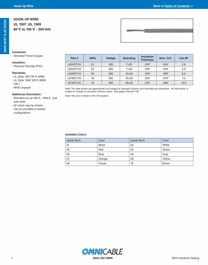
L824ST-XX 24 300 7×30 .016” .054” 2.8
L822ST-XX 22 300 7×30 .016” .059” 3.9
L820ST-XX 20 300 10×30 .016” .069” 6.0
L818ST-XX 18 300 16×30 .016” .079” 7.3
L816ST-XX 16 300 26×30 .016” .089” 10.9
HOOK UP WIRE
UL 1007 ,UL 1569
80°C to 105°C - 300 Volt
Note: The data shown are approximate and subject to standard industry and manufacturer tolerances. All information is subject to change or correction without notice. See pages 139 and 140.
Insert the color number in the XX location.
Conductor:- Stranded Tinned Copper
Insulation:- Polyvinyl Chloride (PVC)
Standards:- UL Style 1007 80°C AWM- UL Style 1569 105°C AWM- VW-1- RHS Cmpliant
Additional Information:- Standard put up 500 ft., 1000 ft., and
bulk reels- All colors may be striped- Can be provided in twisted
configurations
Available Colors:
Jacket Num. Color Jacket Num. Color
01 Black 02 White
03 Red 04 Green
05 Blue 06 Gray
07 Orange 08 Yellow
09 Purple 10 Brown

2
HO
OK
-UP
& L
EA
D W
IRE
(800) 292-OMNI2014 Industrial Catalog
Part # AWG Stranding Insulation Thickness
Nom. O.D. Lbs./M’
L722ST-XX 22 7 .030” .095” 6.3
L720ST-XX 20 10 .030” .099” 7.6
L720SO-XX 20 Solid .030” .096” 7.6
L718ST-XX 18 16 .030” .108” 10
L718SO-XX 18 Solid .030” .105” 10
L716ST-XX 16 26 .030” .120” 14
L716SO-XX 16 Solid .030” .117” 14
L714ST-XX 14 41 .030” .133” 20
L714SO-XX 14 Solid .030” .131” 20
L712ST-XX 12 65 .030” .153” 30
L712SO-XX 12 Solid .030” .146” 30
L710ST-XX 10 105 .030” .189” 42
L710SO-XX 10 Solid .030” .168” 42
L708ST-XX 8 133 .045” .255” 74
L706ST-XX 6 133 .060” .335” 116
L704ST-XX 4 133 .060” .380” 167
L702ST-XX 2 133 .060” .450” 265
High Flex Strand
L708F-XX 8 168 .050” .255” 71
L706F-XX 6 266 .060” .330” 119
L704F-XX 4 420 .060” .380” 173
L703F-XX 3 525 .060” .400” 220
L702F-XX 2 665 .060” .440” 264
L701F-XX 1 836 .080” .510” 342
L71/0F-XX 1/0 1064 .080” .560” 417
L72/0F-XX 2/0 1330 .085” .620” 508
L73/0F-XX 3/0 1672 .085” .680” 636
L74/0F-XX 4/0 2109 .085” .740” 789
L7250F-XX 250 MCM 2451 .100” .800” 955
L7350F-XX 350 MCM 3458 .100” .950” 1273
L7500F-XX 500 MCM 5054 .100” 1.160” 1800
Conductor:- Tinned or bare copper - Stranded or solid
Insulation:- Color coded Polyvinyl Chloride (PVC)
Applications:- Internal wiring of electrical and
electronic equipment and appliances, internal wiring of panels and meters, point to point wiring
Standards:- UL 1015, UL Style 1015, AWM 1015- UL Style TEW, MTW Hook Up Wire- UL Style 1015 600V 105°C- UL Style 1032 1000V 90°C- UL Style 1230 600V 105°C Dry; 60°C Wet- Passes UL VW-1 Flame Test- RoHS Compliant
HOOK UP WIRE
MTW - TEW - AWM
UL 1015, UL 1032, UL 1230
105°C - 600 Volt/1000 Volt
Note: The data shown are approximate and subject to standard industry and manufacturer tolerances. All information is subject to change or correction without notice. See pages 139 and 140.
Insert the color number in the XX location.
Available Colors:
Jacket Num. Color Jacket Num. Color
01 Black 02 White
03 Red 04 Green
05 Blue 06 Gray
07 Orange 08 Yellow
09 Purple 10 Brown
Hook Up Wire Back to Table of Contents >
3
HO
OK
-UP
& LE
AD
WIR
E
(800) 292-OMNI 2014 Industrial Catalog
Available Colors:
Jacket Num. Color Jacket Num. Color
01 Black 02 White
03 Red 04 Green
05 Blue 06 Gray
07 Orange 08 Yellow
09 Purple 10 Brown
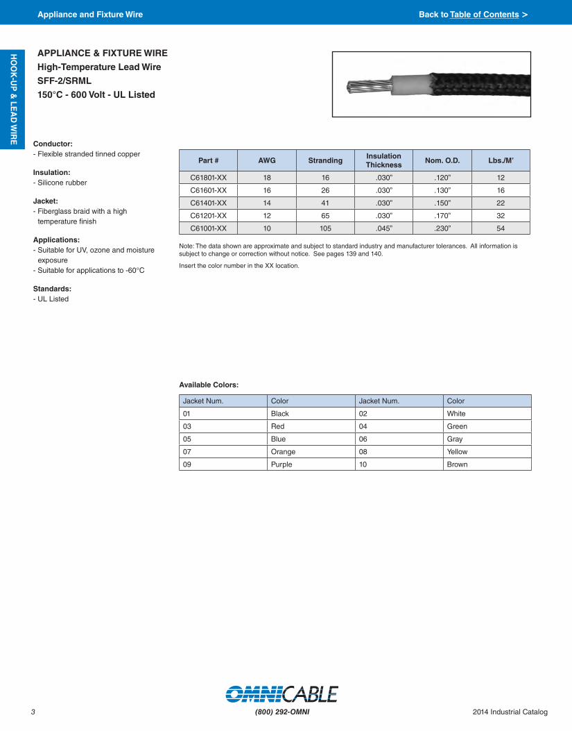
Conductor:- Flexible stranded tinned copper
Insulation:- Silicone rubber
Jacket:- Fiberglass braid with a high
temperature finish
Applications:- Suitable for UV, ozone and moisture
exposure- Suitable for applications to -60°C
Standards:- UL Listed
APPLIANCE & FIXTURE WIRE
High-Temperature Lead Wire
SFF-2/SRML
150°C - 600 Volt - UL Listed
Note: The data shown are approximate and subject to standard industry and manufacturer tolerances. All information is subject to change or correction without notice. See pages 139 and 140.
Insert the color number in the XX location.
Part # AWG Stranding Insulation Thickness
Nom. O.D. Lbs./M’
C61801-XX 18 16 .030” .120” 12
C61601-XX 16 26 .030” .130” 16
C61401-XX 14 41 .030” .150” 22
C61201-XX 12 65 .030” .170” 32
C61001-XX 10 105 .045” .230” 54
Appliance and Fixture Wire Back to Table of Contents >

4
HO
OK
-UP
& L
EA
D W
IRE
(800) 292-OMNI2014 Industrial Catalog
Part # AWG Stranding Insulation Thickness
Nom. O.D. Lbs./M’
C71801-XX 18 7 .030” .120” 12.5
C71601-XX 16 7 .030” .130” 16
C71401-XX 14 7 .030” .145” 22
C71201-XX 12 19 .030” .165” 32
C71001-XX 10 19 .045” .220” 54
Conductor:- Stranded tinned copper
Insulation:- Silicone rubber
Jacket:- Fiberglass braid with a high
temperature finish
Applications:- Suitable for UV, ozone and moisture
exposure- Suitable for applications to -40°C
Standards:- UL Listed
APPLIANCE & FIXTURE WIRE
High-Temperature Lead Wire
SF-2
200°C - 600 Volt - UL Listed
Note: The data shown are approximate and subject to standard industry and manufacturer tolerances. All information is subject to change or correction without notice. See pages 139 and 140.
Insert the color number in the -XX location
Available Colors:
Jacket Num. Color Jacket Num. Color
01 Black 02 White
03 Red 04 Green
05 Blue 06 Gray
07 Orange 08 Yellow
09 Purple 10 Brown
Appliance and Fixture Wire Back to Table of Contents >

5
HO
OK
-UP
& LE
AD
WIR
E
(800) 292-OMNI 2014 Industrial Catalog
Conductor:- Stranded tinned copper
Insulation:- Moisture and flame retardant
Cross-linked Polyethylene (XLPE) VW-1
Applications:- Switchboard wiring, industrial control
panel and other types of control apparatus.
Additional Information:- Available in larger sizes- Also available in Class B stranding- All colors may be striped- All colors may be twisted- Acceptable as motor leads or for
internal wiring of appliances* Sizes 18 AWG and 16 AWG are not
listed as type SIS switchboard, but rather as “Suitable for SIS and are not VW-1 Rated.” Listed as Appliance Wiring Material per UL Style 3173 and rated by UL as 600 Volts, 125°C; 90°C when used as Type SIS.
SWITCHBOARD WIRE
Switchboard Type SIS*
90°C - 600 Volt - VW-1
Note: The data shown are approximate and subject to standard industry and manufacturer tolerances. All information is subject to change or correction without notice. See pages 139 and 140.
Insert the color number in the XX location.
Part # AWG Stranding Insulation Thickness
Nom. O.D. Lbs./M’
C81801-XX* 18 16 .030” .107” 11
C81601-XX* 16 26 .030” .117” 13
C81401-XX 14 41 .030” .133” 20
C81407-XX 14 7 .030” .132” 20
C81201-XX 12 65 .030” .153” 30
C81207-XX 12 7 .030” .152” 30
C81001-XX 10 105 .030” .195” 42
C80801-XX 8 133 .045” .261” 74
C80601-XX 6 133 .060” .305” 107
C80401-XX 4 133 .045” .368” 163
C80201-XX 2 133 .045” .434” 243
Available Colors:
Jacket Num. Color Jacket Num. Color
01 Black 02 White
03 Red 04 Green
05 Blue 06 Gray
07 Orange 08 Yellow
09 Purple 10 Brown
Switchboard Wire Back to Table of Contents >
6
HO
OK
-UP
& L
EA
D W
IRE
(800) 292-OMNI2014 Industrial Catalog
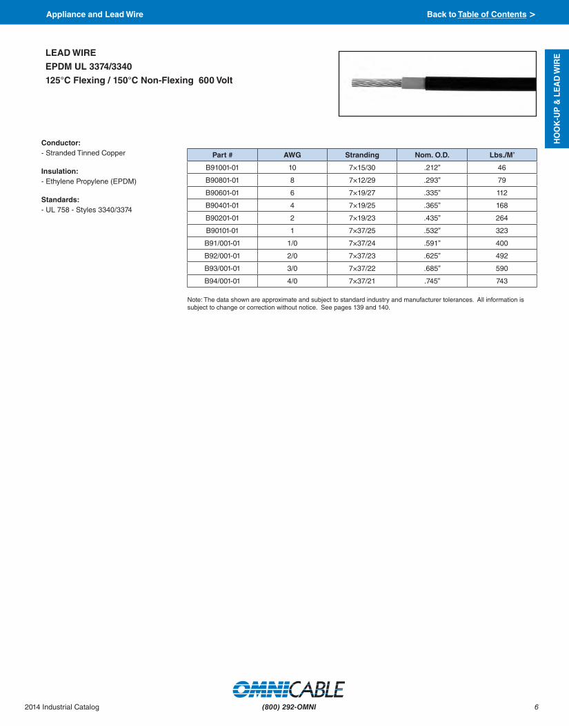
Conductor:- Stranded Tinned Copper
Insulation:- Ethylene Propylene (EPDM)
Standards:- UL 758 - Styles 3340/3374
LEAD WIRE
EPDM UL 3374/3340
125°C Flexing / 150°C Non-Flexing 600 Volt
Note: The data shown are approximate and subject to standard industry and manufacturer tolerances. All information is subject to change or correction without notice. See pages 139 and 140.
Part # AWG Stranding Nom. O.D. Lbs./M’
B91001-01 10 7×15/30 .212” 46
B90801-01 8 7×12/29 .293” 79
B90601-01 6 7×19/27 .335” 112
B90401-01 4 7×19/25 .365” 168
B90201-01 2 7×19/23 .435” 264
B90101-01 1 7×37/25 .532” 323
B91/001-01 1/0 7×37/24 .591” 400
B92/001-01 2/0 7×37/23 .625” 492
B93/001-01 3/0 7×37/22 .685” 590
B94/001-01 4/0 7×37/21 .745” 743
Appliance and Lead Wire Back to Table of Contents >

7
HO
OK
-UP
& LE
AD
WIR
E
(800) 292-OMNI 2014 Industrial Catalog
Part # AWG Stranding TFE Wall
Thick. Fiberglass
Serve Fiber-glass
Braid Nom. O.D. Lbs./M’
C41801 18 16 .007” .004” .005” .078” 13
C41601 16 26 .011” .004” .005” .092” 17
C41401 14 41 .011” .004” .005” .113” 23
C41201 12 65 .011” .004” .005” .127” 32
C41001 10 105 .011” .004” .005” .155” 48
C40801 8 133 .011” .004” .005” .210” 72
C40601 6 133 .014” .006” .006” .265” 120
C40401 4 133 .014” .006” .006” .320” 175
C40201 2 133 .014” .006” .006” .390” 270
C40101 1 259 .020” .015” .017” .485” 320
C41/001 1/0 259 .020” .015” .017” .535” 397
C42/001 2/0 259 .020” .015” .017” .585” 490
C43/001 3/0 259 .020” .015” .017” .645” 598
C44/001 4/0 259 .020” .015” .017” .710” 765
Conductor:- Stranded nickel coated (2%) copper
Insulation:- Polytetrafluoroethylene (PTFE) tape
with glass serve
Jacket:- Fiberglass braid with a high
temperature finish
Applications:- Internal wiring of heating equipment,
cooking equipment, and heat producing apparatus in domestic and industrial cooking environments.
- Ideal for use in equipment wiring in iron and steel mills, cement kilns, and glass plants.
Standards`:- UL Style 5256
LEAD WIRE
Type TGGT
PTFE Insulation - Fiberglass Jacket
250°C - 600 Volt - UL 5256/5251
Note: The data shown are approximate and subject to standard industry and manufacturer tolerances. All information is subject to change or correction without notice. See pages 139 and 140.
Appliance and Lead Wire Back to Table of Contents >

8
HO
OK
-UP
& L
EA
D W
IRE
(800) 292-OMNI2014 Industrial Catalog
Part # AWG Stranding Nominal Thickness
Nom. O.D. Lbs./M’Insulation Jacket
C31801 18 16 .025” .007” .115” 12
C31601 16 26 .025” .007” .125” 16
C31401 14 41 .025” .007” .140” 23
C31201 12 65 .025” .007” .160” 31
C31001 10 105 .030” .017” .210” 52
C30801 8 133 .030” .017” .265” 78
C30601 6 133 .030” .017” .310” 115
C30401 4 133 .030” .017” .365” 175
C30201 2 133 .035” .020” .450” 260
C30101 1 259 .035” .020” .490” 320
C31/001 1/0 259 .035” .020” .535” 400
C32/001 2/0 259 .035” .020” .590” 505
C33/001 3/0 259 .035” .020” .650” 620
C34/001 4/0 259 .035” .020” .710” 760
Conductor:- Flexible stranded 27% nickel plated,
annealed copper
Insulation:- Glass reinforced mica tape
Jacket:- Fiberglass braid with a high
temperature finish
Applications:- Internal wiring of domestic and
commercial ovens and cooking appliances in very high temperature environments.
- Ideal for use in equipment wiring in iron and steel mills, cement kilns, and glass plants.
- 450° continuous / 538°C temporary
Standards:- UL Style 5107, 5359
LEAD WIRE
Type MG - Single Conductor
Fiberglass Braid
450°C - 600 Volt
Note: The data shown are approximate and subject to standard industry and manufacturer tolerances. All information is subject to change or correction without notice. See pages 139 and 140.
Appliance and Lead Wire Back to Table of Contents >

9
HO
OK
-UP
& LE
AD
WIR
E
(800) 292-OMNI 2014 Industrial Catalog
Conductor:- Flexible stranded 27% nickel plated,
annealed copper
Insulation:- Glass reinforced mica tape
Jacket:- Fiberglass braid with a high temperature
finish
Applications:- Internal wiring of domestic and
commercial ovens and cooking appliances in very high temperature environments
- Ideal for use in equipment wiring in iron and steel mills, cement kilns, and glass plants
- 450° continuous / 538°C temporary
Standards:- NEMA WC 3 Flame Propagation Test- IEEE-383
LEAD WIRE
Type MG - Multi-Conductor
Fiberglass Braid
450°C - 600 Volt
Note: The data shown are approximate and subject to standard industry and manufacturer tolerances. All information is subject to change or correction without notice. See pages 139 and 140.
Part # AWG Conductors Stranding Nominal Thickness
Nom. O.D. Lbs./M’ Insulation Jacket
C31803 18 3 16 .025” .007” .327” 55
C31804 18 4 16 .025” .007” .345” 69
C31403 14 3 41 .025” .017” .390” 93
C31405 14 5 41 .025” .017” .469” 147
C31202 12 2 65 .025” .017” .400” 87
C31203 12 3 65 .025” .017” .426” 120
Appliance and Lead Wire Back to Table of Contents >

10
HO
OK
-UP
& L
EA
D W
IRE
(800) 292-OMNI2014 Industrial Catalog
Conductor:- Annealed tinned copper
Insulation:- Silicone rubber, fiberglass braid
Jacket:- Aramid fiber braid
Color Code:- Stocked in K2/E2 color code with a black
jacket. Other options available upon request.
Applications:- Used for leads to motors, transformers
or other electrical equipment where hazardous and/or high temperature conditions exist requiring flexible heat resistant conductors at 600 volts
Standards:- NEMA WC 3 Flame Propagation Test- IEEE-383 Vertical Cable Tray Flame Test
MOTOR LEAD WIRE
SRG-K
200°C - 600 Volt
Note: The data shown are approximate and subject to standard industry and manufacturer tolerances. All information is subject to change or correction without notice. See pages 139 and 140.
Part # AWG Conductors Stranding Kevlar
Thickness Nom. O.D. Lbs./M’
C51403 14 3 7 .030” .400” 75
C51404 14 4 7 .030” .435” 100
C51405 14 5 7 .030” .480” 125
C51407 14 7 7 .030” .520” 170
C51203 12 3 19 .030” .430” 110
C51204 12 4 19 .030” .475” 145
C51205 12 5 19 .030” .520” 175
C51207 12 7 19 .030” .570” 240
Color Code Chart:
Cond. Num. Color Cond. Num. Color1 Black 2 Red3 Blue 4 Orange5 Yellow 6 Brown7 Red w/ Black Stripe
Appliance and Lead Wire Back to Table of Contents >

11
HO
OK
-UP
& LE
AD
WIR
E
(800) 292-OMNI 2014 Industrial Catalog
Part # AWG Stranding Insulation Thickness
Braid Nom. O.D. Lbs./M’
C50801 8 133 .060” .005” .315” 91
C50601 6 133 .060” .005” .355” 135
C50401 4 133 .060” .005” .410” 196
C50201 2 133 .060” .005” .475” 288
C50101 1 259 .080” .005” .585” 359
C51/001 1/0 259 .080” .007” .610” 468
C52/001 2/0 259 .080” .007” .655” 545
C53/001 3/0 259 .080” .007” .728” 660
C54/001 4/0 259 .080” .007” .802” 820
C525001* 250 427 .095” .040” .890” 985
C535001* 350 427 .095” .040” 1.03” 1330
C550001* 500 427 .095” .040” 1.18” 1885
C575001* 750 703 .110” .040” 1.49” 2715
Conductor:- Flexible stranded tinned copper
Insulation:- Silicone rubber
Jacket:- Fiberglass braid with a high
temperature finish
Applications:- Used in wiring of electrical equipment
in hazardous locations where exposure to temperature does not exceed 200°C
Standards:- UL Style 3231, 3101, 3127, 3069, 3070
MOTOR LEAD WIRE
SRML
150°C - 600 Volt
Note: The data shown are approximate and subject to standard industry and manufacturer tolerances. All information is subject to change or correction without notice. See pages 139 and 140.
Appliance and Lead Wire Back to Table of Contents >

12
BU
ILD
ING
WIR
E
(800) 292-OMNI2014 Industrial Catalog
Available Colors:
Jacket Num. Color Jacket Num. Color
01 Black 02 White
03 Red 04 Green
05 Blue 06 Gray
07 Orange 08 Yellow
09 Purple 10 Brown
11 Pink 12 Tan
Part # AWG Stranding Insulation Thickness.
Nom. O.D. Lbs./M’
Stranded
M714ST-XX 14 7 .030” .133” 18
M712ST-XX 12 7 .030” .158” 27
M710ST-XX 10 7 .030” .180” 40
M708ST-XX 8 7 .045” .240” 75
M706ST-XX 6 7 .045” .280” 112
M704ST-XX 4 7 .045” .328” 153
M703ST-XX 3 7 .045” .355” 186
M702ST-XX 2 7 .045” .380” 262
M701ST-XX 1 19 .055” .434” 300
M71/0ST-XX 1/0 19 .055” .473” 363
M72/0ST-XX 2/0 19 .055” .517” 452
M73/0ST-XX 3/0 19 .055” .567” 562
M74/0ST-XX 4/0 19 .055” .623” 702
M7250ST-XX 250 37 .065” .705” 835
M7300ST-XX 300 37 .065” .760” 990
M7350ST-XX 350 37 .065” .810” 1155
M7400ST-XX 400 37 .065” .850” 1337
M7500ST-XX 500 37 .065” .940” 1630
M7600ST-XX 600 61 .110” 1.04” 1965
M7100ST-XX 1000 61 .110” 1.30” 3235
Solid
M714SO-XX 14 Solid .030” .139” 21
M712SO-XX 12 Solid .030” .155” 27
M710SO-XX 10 Solid .030” .179” 40
M708SO-XX 8 Solid .045” .220” 66
M706SO-XX 6 Solid .045” .260” 100
M704SO-XX 4 Solid .045” .300” 153
Conductor:- Bare annealed copper, Class B
stranding
Insulation:- Moisture and flame retardant thermoset
Cross-linked Polyethylene (XLPE)
Applications:- Recognized for use as general
purpose wiring at maximum conductor temperature of 90°C in dry and wet locations
- For installation in air, conduit, or other recognized raceways in circuits not exceeding 600 volts
- Tray cable ratings available upon request for sizes 1/0 AWG and larger
- Sunlight-resistant available
Standards:- National Electric Code (NEC)- UL 44 Standard for Rubber Insulated
Wire and Cable- UL Listed as Type XHHW-2- OSHA Acceptable- UL 1685
Features:General purpose use in construction:- Residential- Commercial- Institutional- Industrial construction
Additional Information:- All colors may be striped- Can be provided in twisted
configurations
BUILDING WIRE
XHHW-2
90°C - 600 Volt
Note: The data shown are approximate and subject to standard industry and manufacturer tolerances. All information is subject to change or correction without notice. See pages 139 and 140.
Insert the color number in the XX location.
Building Wire Back to Table of Contents >

13
BU
ILD
ING
WIR
E
(800) 292-OMNI 2014 Industrial Catalog
Available Colors:
Jacket Num. Color Jacket Num. Color
01 Black 02 White
03 Red 04 Green
05 Blue 06 Gray
07 Orange 08 Yellow
09 Purple 10 Brown
Part # AWG Stranding Insulation Thickness
Nom. O.D. Lbs./M’
M614ST-XX 14 7 .045” .162” 22
M612ST-XX 12 7 .045” .188” 30
M610ST-XX 10 7 .045” .212” 45
M608ST-XX 8 7 .060” .270” 73
M606ST-XX 6 7 .060” .310” 107
M604ST-XX 4 7 .060” .360” 161
M602ST-XX 2 7 .060” .420” 244
M601ST-XX 1 19 .080” .490” 325
M61/0ST-XX 1/0 19 .080” .530” 399
M62/0ST-XX 2/0 19 .080” .580” 491
M63/0ST-XX 3/0 19 .080” .630” 585
M64/0ST-XX 4/0 19 .080” .690” 751
M6250ST-XX 250 37 .095” .770” 865
M6300ST-XX 300 37 .095” .820” 1030
M6350ST-XX 350 37 .095” .880” 1190
M6400ST-XX 400 37 .095” .920” 1350
M6500ST-XX 500 37 .110” 1.03” 1670
M6600ST-XX 600 61 .110” 1.11” 2015
M6750ST-XX 750 61 .110” 1.22” 2495
M61000ST-XX 1000 61 .110” 1.35” 3290
Conductor:- Bare annealed copper, Class B
stranding per ASTM B8
Insulation:- Flame-retardant Cross-linked
Polyethylene (XLPE), black
Applications:- Recognized for use as general
purpose wiring at maximum conductor temperature of 90°C in dry and wet locations
- For installation in air, conduit, or other recognized raceways in circuits not exceeding 600 volts
- Tray cable rated available upon request for 1/0 and larger
Standards:- National Electric Code (NEC)- UL 44 Type RHH or RHW-2- UL 854 Type USE-2- UL 1581 VW-1- 1/0 & larger: IEEE 383, IEEE 1202- OSHA Acceptable
Features:- Conductor for reduced diameterGeneral purpose use in construction:- Residential- Commercial- Institutional- Industrial construction
Additional Information:- Can be provided in twisted
configurations up to 10 AWG- Sunlight and/or oil resistant available
upon request
BUILDING WIRE
XLPE/USE-2 - RHH - RHW-2
90°C - 600 Volt
Note: The data shown are approximate and subject to standard industry and manufacturer tolerances. All information is subject to change or correction without notice. See pages 139 and 140.
Insert the color number in the XX location.
Building Wire Back to Table of Contents >

14
BU
ILD
ING
WIR
E
(800) 292-OMNI2014 Industrial Catalog
Conductor:- 18 AWG - 2 AWG - Tinned coated
compressed copper, Class C stranding per ASTM B33 and B8
- 1 AWG - 4/0 - Tinned coated compressed copper, Class B stranding per ASTM B33 and B8
Insulation:- Flame-retardant Cross-linked
Polyethylene (XLPE), black
Applications:- Single conductor, sunlight resistant,
photovoltaic wire rated 90°C wet or dry, 600V for interconnection wiring of grounded and ungrounded photovoltaic power systems as described in Section 690.31(A) and other applicable parts of the National Electrical Code, NFPA 70
Standards:- UL 4703 Type PV- National Electric Code (NEC)- UL 44 Type RHH or RHW-2- UL 854 Type USE-2- UL 1581 VW-1- 1/0 & larger: IEEE 383, IEEE 1202- OSHA Acceptable
BUILDING WIRE
RHH - RHW-2
UL Photovoltaic
90°C - 600 Volt
Note: The data shown are approximate and subject to standard industry and manufacturer tolerances. All information is subject to change or correction without notice. See pages 139 and 140.
Colors available upon request
Part # AWG Stranding Insulation Thickness
Nom. O.D. Lbs./M’
PV31801 18 19 0.060” .176” 14
PV31601 16 19 0.060” .187” 18
PV31401 14 19 0.060” .198” 27
PV31201 12 19 0.060” .216” 36
PV31001 10 19 0.060” .235” 51
PV30801 8 19 0.075” .295” 80
PV30601 6 19 0.075” .335” 115
PV30401 4 19 0.075” .385” 170
PV30201 2 19 0.075” .450” 253
PV30101 1 19 0.095” .515” 333
PV31/001 1/0 19 0.095” .555” 410
PV32/001 2/0 19 0.095” .600” 502
PV33/001 3/0 19 0.095” .650” 620
PV34/001 4/0 19 0.095” .705” 767
Building Wire Back to Table of Contents >

15
INS
TR
UM
EN
TAT
ION
(800) 292-OMNI 2014 Industrial Catalog
Conductor:- Annealed Tinned Copper- 19 strands Class C
Insulation:- Polyvinyl Chloride (PVC)- Color code: Black, Red
Shield:- Aluminum Mylar Tape - 100% coverage
Drain Wire:- 7 Strand Tinned Copper
Jacket:- Polyvinyl Chloride (PVC)
Applications:- Cable is suitable for use in Class I
Divison II hazardous locations- Cable is UL approved for Sunlight
Resistant and Direct Burial Applications- Recommended Operating Voltage:
- 300V
Standards:- UL listed as type PLTC & CL3 per UL
standard 13 and as type ITC per UL standard 2250
- Meets IEEE 1202 flame test- All materials used in the manufacture
of this cable are RoHS compliant
INSTRUMENTATION CABLE
PVC Jacket & Insulation
Overall Shield
105°C - 300 Volt - UL PLTC/ITC
16 AWG - 22 AWG
Note: The data shown are approximate and subject to standard industry and manufacturer tolerances. All information is subject to change or correction without notice. See pages 139 and 140.
Part # AWG ConductorsNominal Thickness Jacket
Color Nom. O.D. Lbs./M’
Insulation Jacket
KT32202 22 2 .013" .037" Gray .191" 19
KT32002 20 2 .016" .037" Gray .220" 29
KT31802 18 2 .016" .037" Gray .242" 37
KT31602 16 2 .016" .037" Gray .256" 45
300 Volt Back to Table of Contents >

16
INS
TR
UM
EN
TAT
ION
(800) 292-OMNI2014 Industrial Catalog
Conductor:- Annealed bare copper- 7 Strands Class B
Insulation:- Polyvinyl Chloride (PVC)
Shield:- Aluminum Mylar Tape - 100% coverage
Drain Wire:- 7 Strand tinned copper
Jacket:- Black Polyvinyl Chloride (PVC)
Applications:- Cable is suitable for use in Class I
Division II hazardous locations- Cable is UL approved for Sunlight
Resistant and Direct Burial Applications
Standards: - UL listed as type PLTC & CL3 per UL
standard 13 and as type ITC per UL standard 2250
- Meets IEEE 1202 flame test- All materials used in the manufacture
of this cable are RoHS compliant
INSTRUMENTATION CABLE
PVC Jacket & Insulation
Single Pair & Triad
105°C - 300 Volt - UL PLTC/ITC
Note: The data shown are approximate and subject to standard industry and manufacturer tolerances. All information is subject to change or correction without notice. See pages 139 and 140.
*K31602-05 has a blue jacket
Color Code Chart:
Pairs Black and White
Triads Black, White, and Red
Part # AWG Pairs Triads Nominal Thickness Nom.
O.D. Lbs./M’
Insulation Jacket
Shielded
K32202 22 1 - .013" .040" .191" 22
K32002 20 1 - .016" .035" .215" 27
K42003 20 - 1 .016" .035" .217" 31
K31802 18 1 - .016" .035" .226" 33
K41803 18 - 1 .016" .035" .247" 42
K31602 16 1 - .016" .035" .254" 44
K31602-05* 16 1 - .016" .035" .254" 44
K41603 16 - 1 .016" .035" .266" 56
Nonshielded (Non Standard)
K11602 16 1 - .016" .035" .247" 38
300 Volt Back to Table of Contents >

17
INS
TR
UM
EN
TAT
ION
(800) 292-OMNI 2014 Industrial Catalog
Conductor:- Annealed Bare Copper- 7 Strands Class B
Insulation:- Polyvinyl Chloride (PVC)
Individual Shield: - FFE Aluminum Mylar - 100% coverage
Pair Drain Wire:- 7 Strand Tinned Copper
Overall Shield:- Aluminum Mylar Tape - 100% coverage
Drain Wire:- 7 Strand Tinned Copper
Jacket:- Black Polyvinyl Chloride (PVC) with
ripcord
Applications:- Cable is suitable for use in Class I
Division II hazardous locations- Cable is UL approved for Sunlight
Resistant and Direct Burial Applications
Standards:- UL listed as type PLTC & CL3 per UL
standard 13 and as type ITC per UL standard 2250
- Meets CSA standard C22.2 #239 C(UL) CIC 300V 90°C
- Meets IEEE 1202 flame test- All materials used in the manufacture
of this cable are RoHS compliant
INSTRUMENTATION CABLE
PVC Jacket
PVC Insulation
Individual & Overall Shielded Pairs
105°C - 300 Volt - UL PLTC/ITC
Note: The data shown are approximate and subject to standard industry and manufacturer tolerances. All information is subject to change or correction without notice. See pages 139 and 140.
Type Color
Pairs Black, White & Numbered
Part # AWG PairsNominal Thickness
Nom. O.D. Lbs./M’Insulation Jacket
L32002 20 2 .018" .040" .339" 58
L32004 20 4 .018" .050" .410" 101
L32008 20 8 .018" .050" .553" 175
L32012 20 12 .018" .060" .688" 261
L32016 20 16 .018" .060" .760" 330
L32020 20 20 .018" .060" .783" 390
L32024 20 24 .018" .060" .867" 462
L32036 20 36 .018" .070" 1.076" 687
L32050 20 50 .018" .070" 1.185" 906
L31802 18 2 .016" .040" .335" 71
L31804 18 4 .016" .050" .425" 125
L31808 18 8 .016" .050" .559" 220
L31812 18 12 .016" .060" .699" 326
L31816 18 16 .016" .060" .753" 410
L31820 18 20 .016" .060" .817" 501
L31824 18 24 .016" .070" .941" 613
L31836 18 36 .016" .070" 1.061" 868
L31850 18 50 .016" .080" 1.252" 1198
L31602 16 2 .016" .050" .410" 106
L31603 16 3 .016" .050" .462" 140
L31604 16 4 .016" .050" .505" 173
L31606 16 6 .016" .060" .623" 256
L31608 16 8 .016" .060" .676" 323
L31612 16 12 .016" .060" .771" 454
L31616 16 16 .016" .060" .851" 581
L31620 16 20 .016" .070" 1.008" 738
L31624 16 24 .016" .070" 1.051" 859
L31636 16 36 .016" .080" 1.271" 1265
L31650 16 50 .01 6" .080" 1.439" 1704
Color Code Chart:
300 Volt Back to Table of Contents >

18
INS
TR
UM
EN
TAT
ION
(800) 292-OMNI2014 Industrial Catalog
Conductor:- Annealed Bare Copper- 7 Strands Class B
Insulation:- Polyvinyl Chloride (PVC)
Shield:- Aluminum Mylar Tape - 100% coverage
Drain Wire:- 7 Strand Tinned Copper
Jacket:- Black Polyvinyl Chloride (PVC) with
ripcord
Applications:- Cable is suitable for use in Class I
Division II hazardous locations- Cable is UL approved for Sunlight
Resistant Applications- Recommended Operating Voltage: 300V
Standards:- UL listed as type PLTC & CL3 per UL
standard 13 and as type ITC per UL standard 2250
- Meets IEEE 1202 flame test- All materials used in the manufacture
of this cable are RoHS compliant
INSTRUMENTATION CABLE
PVC Jacket
PVC Insulation
Overall Shielded Pairs
105°C - 300 Volt - UL PLTC/ITC
Note: The data shown are approximate and subject to standard industry and manufacturer tolerances. All information is subject to change or correction without notice. See pages 139 and 140.
Color Code Chart:
Type Color
Pairs Black, White & Numbered
Part # AWG Pairs Nominal Thickness
Nom. O.D. Lbs./M’ Insulation Jacket
L12002 20 2 .018” .040” .255” 41
L12004 20 4 .018” .040” .373” 78
L12008 20 8 .018” .050” .502” 141
L12012 20 12 .018” .050” .604” 198
L12016 20 16 .018” .060” .689” 264
L12024 20 24 .018” .060” .826” 373
L12036 20 36 .018” .070” .989” 546
L11802 18 2 .015” .042” .325” 82
L11804 18 4 .015” .042” .357” 133
L11808 18 8 .015” .060” .646” 285
L11602 16 2 .015” .042” .344” 109
L11604 16 4 .015” .053” .442” 197
L11608 16 8 .015” .060” .726” 259
L11612 16 12 .015” .060” .755” 408
L11616 16 16 .015” .070” .845” 526
L11620 16 20 .015” .070” .905” 655
L11624 16 24 .015” .070” 1.13” 803
L11636 16 36 .015” .070” 1.17” 1122
L11650 16 50 .015” .080” 1.36” 1544
300 Volt Back to Table of Contents >

19
INS
TR
UM
EN
TAT
ION
(800) 292-OMNI 2014 Industrial Catalog
Conductor:- Annealed Bare Copper- 7 Strands Class B
Insulation:- Polyvinyl Chloride (PVC)
Individual Shield:- FFE Aluminum Mylar Tape - 100%
coverage
Triad Drain Wire:- 7 Strand Tinned Copper
Overall Shield:- FFE Aluminum Mylar Tape - 100%
coverage
Drain Wire:- 7 Strand Tinned Copper
Jacket:- Black Polyvinyl Chloride (PVC) with
ripcord
Applications:- Cable is suitable for use in Class I
Division II hazardous locations- Cable is UL approved for Sunlight
Resistant Applications
Standards:- UL listed as type PLTC & CL3 per UL
standard 13 and as type ITC per UL standard 2250
- Meets IEEE 1202 flame test- All materials used in the manufacture
of this cable are RoHS compliant
INSTRUMENTATION CABLE
PVC Jacket & Insulation
Individual & Overall Shielded Triads
105°C - 300 Volt - UL PLTC/ITC
Note: The data shown are approximate and subject to standard industry and manufacturer tolerances. All information is subject to change or correction without notice. See pages 139 and 140.
Color Code Chart:
Type Color
Triads Black, White, Red & Numbered
Part # AWG Triads Nominal Thickness
Nom. O.D. Lbs./M’ Insulation Jacket
L62002 20 2 .018” .050” .433” 88
L62004 20 4 .018" .050" .500" 133
L62008 20 8 .018" .050" .596" 226
L62012 20 12 .018" .060" .812" 349
L62024 20 24 .018" .070" 1.103" 652
L62036 20 36 .018" .080" 1.318" 954
L61802 18 2 .015" .040" .321" 77
L61804 18 4 .015" .050" .444" 143
L61808 18 8 .015" .060" .691" 275
L61812 18 12 .015" .060" .840" 412
L61816 18 16 .015" .070" .960" 550
L61820 18 20 .015" .070" 1.06" 668
L61824 18 24 .015" .070" 1.15" 785
L61836 18 36 .015" .080" 1.37" 1151
L61602 16 2 .015" .040" .367" 104
L61604 16 4 .015" .050" .502" 195
L61608 16 8 .015" .060" .786" 375
L61612 16 12 .015" .070" .970" 597
L61616 16 16 .015" .070" 1.08" 765
L61620 16 20 .015" .070" 1.20" 933
L61624 16 24 .015" .080" 1.31" 1125
L61636 16 36 .015" .080" 1.54" 1620
300 Volt Back to Table of Contents >

20
INS
TR
UM
EN
TAT
ION
(800) 292-OMNI2014 Industrial Catalog
Conductor:- Annealed Bare Copper- 7 Strands Class B
Insulation:- Polyvinyl Chloride (PVC) & Nylon
Individual Shield:- Foil Free Edged Aluminum Mylar Tape
- 100% coverage
Pair Drain Wire:- 7 Strand Tinned Copper
Drain Wire:- 7 Strand Tinned Copper
Overall Shield:- Aluminum Mylar Tape - 100% coverage
Jacket:- Black Polyvinyl Chloride (PVC)
Applications:- Refer to NEC (NFPA 70) article 1277
for installation guidelines- Cable is suitable for use in Class I
Division II hazardous locations- UL approved for Direct Burial, Sunlight
and Oil Resistant applications
Standards:- RoHS compliant- UL 1581 & 1202 (FT-4)- UL 1277 Type TC-ER
INSTRUMENTATION CABLE
PVC Jacket & Insulation
Individual & Overall Shielded Pairs
90°C - 600 Volt - UL Type TC-ER
Note: The data shown are approximate and subject to standard industry and manufacturer tolerances. All information is subject to change or correction without notice. See pages 139 and 140.
Color Code Chart:
Part # AWG Pairs Nominal Thickness
Nom. O.D. Lbs./M’ Insulation Jacket
L41802 18 2 .015” .045” .373” 77
L41803 18 3 .015” .045” .435” 104
L41804 18 4 .015” .045” .445” 125
L41806 18 6 .015” .060” .578” 196
L41808 18 8 .015” .060” .599” 237
L41812 18 12 .015” .060” .725” 337
L41816 18 16 .015” .080” .891” 470
L41820 18 20 .015” .080” .912” 555
L41824 18 24 .015” .080” 1.003” 652
L41836 18 36 .015” .080” 1.221” 934
L41850 18 50 .015” .080” 1.411” 1251
L41602 16 2 .015” .045” .425” 103
L41603 16 3 .015” .045” .493” 140
L41604 16 4 .015” .060” .544” 189
L41606 16 6 .015” .060” .648” 266
L41608 16 8 .015” .060” .708” 333
L41612 16 12 .015” .080” .886” 509
L41616 16 16 .015” .080” .971” 640
L41620 16 20 .015” .080” 1.061” 776
L41624 16 24 .015” .080” 1.136” 908
L41636 16 36 .015” .080” 1.334” 1302
L41650 16 50 .015” .080” 1.571” 1762
L41402 14 2 .015” .045” .496” 144
L41404 14 4 .015” .060” .616” 262
L41408 14 8 .015” .060” .757” 461
L41412 14 12 .015” .080” .958” 698
L41416 14 16 .015” .080” 1.060” 894
L41420 14 20 .015” .080” 1.150” 1089
L41424 14 24 .015” .080” 1.291” 1291
L41436 14 36 .015” .080” 1.494” 1861
L41450 14 50 .015” .110” 1.774” 2629
Type Color
Pairs Black, White & Numbered
600 Volt Back to Table of Contents >

21
INS
TR
UM
EN
TAT
ION
(800) 292-OMNI 2014 Industrial Catalog
Conductor:- Annealed Bare Copper- 7 Strands Class B
Insulation:- Polyvinyl Chloride (PVC) & Nylon
Shield:- Aluminum Mylar Tape - 100% coverage
Drain Wire:- 7 Strand Tinned Copper
Jacket:- Black Polyvinyl Chloride (PVC)
Applications:- Refer to NEC (NFPA 70) article 1277
for installation guidelines- Cable is suitable for use in Class I
Division II hazardous locations- UL approved for Direct Burial, Sunlight
and Oil Resistant applications- Cold Bend Rating -40°C
Standards:- RoHS compliant- UL 1581 & 1202 (FT-4)- UL 1277 Type TC-ER
INSTRUMENTATION CABLE
PVC Jacket & Insulation
Overall Shielded Pairs
90°C - 600 Volt - UL Type TC-ER
Note: The data shown are approximate and subject to standard industry and manufacturer tolerances. All information is subject to change or correction without notice. See pages 139 and 140.
Color Code Chart:
Part # AWG Pairs Nominal Thickness
Nom. O.D. Lbs./M’ Insulation Jacket
L21802 18 2 .015” .045” .346” 67
L21804 18 4 .015” .045” .450” 109
L21806 18 6 .015” .060” .557” 166
L21808 18 8 .015” .060” .628” 210
L21812 18 12 .015” .060” .731” 288
L21816 18 16 .015” .060” .786” 360
L21824 18 24 .015” .080” .971” 547
L21836 18 36 .015” .080” 1.331” 804
L21602 16 2 .015” .045” .417” 91
L21603 16 3 .015” .045” .443” 117
L21604 16 4 .015” .045” .487” 146
L21605 16 5 .015” .060” .567” 192
L21606 16 6 .015” .060” .643” 229
L21608 16 8 .015” .060” .666” 279
L21612 16 12 .015” .060” .778” 388
L21616 16 16 .015” .080” .934” 537
L21624 16 24 .015” .080” 1.151” 766
L21402 14 2 .020” .050” .565” 120
L21404 14 4 .020” .060” .600” 257
L21406 14 6 .020” .060” .685” 295
L21408 14 8 .020” .060” .773” 428
L21412 14 12 .020” .080” .985” 655
L21416 14 16 .020” .080” 1.10” 835
L21420 14 20 .020” .080” 1.19” 1035
L21424 14 24 .020” .080” 1.33” 1250
L21436 14 36 .020” .080” 1.55” 1675
L21450 14 50 .020” .110” 1.83” 2435
Type Color
Pairs Black, White & Numbered
600 Volt Back to Table of Contents >

22
INS
TR
UM
EN
TAT
ION
(800) 292-OMNI2014 Industrial Catalog
Conductor:- Tinned, annealed copper per ASTM B33- Class B stranding per ASTM B8
Insulation:- Flame retardant Ethylene Propylene
Rubber (EPR), Type II
Individual Shield:- Aluminum/mylar shielding tape
Pair & Overall Drain Wires:- Stranded, tinned copper
Overall Shield:- Aluminum/mylar shielding tape
Jacket:- Lead-free, flame retardant, thermoplastic
Chlorinated Polyethylene (CPE)
Applications:- In free air, raceways and direct burial- In wet or dry locations- Approved for direct burial- Class 1, Division 2 industrial hazardous
locations per NEC
Approvals:- IEEE 383 - IEEE 1202 - UL 1581/UL 2556 VW-1- UL 1685 Vertical Flame Test- UL 1277 Type TC-ER
INSTRUMENTATION CABLE
CPE Jacket - EPR Insulation
Individual & Overall Shielded Pairs
90°C - 600 Volt - UL Type TC-ER
Note: The data shown are approximate and subject to standard industry and manufacturer tolerances. All information is subject to change or correction without notice. See pages 139 and 140.
** Part number AF61801 does NOT have individually shielded pairs, only overall shielded pairs. ER Rating only applies to 3 conductors or more.
Color Code Chart:
Part # AWG Pairs Nominal Thickness
Nom. O.D. Lbs./M’ Insulation Jacket
AF61801** 18 1 .025” .045” .300” 42
AF61802 18 2 .025” .045” .473” 83
AF61804 18 4 .025” .060” .586” 152
AF61806 18 6 .025” .060” .669” 206
AF61808 18 8 .025” .060” .751” 259
AF61812 18 12 .025” .080” .948” 398
AF61816 18 16 .025” .080” 1.05” 502
AF61818 18 18 .025” .080” 1.10” 553
AF61820 18 20 .025” .080” 1.14” 603
AF61824 18 24 .025” .080” 1.25” 709
AF61836 18 36 .025” .080” 1.47” 1008
AF61850 18 50 .025” .110” 1.76” 1454
AF61601 16 1 .025” .045” .318” 59
AF61602 16 2 .025” .045” .516” 103
AF61603 16 3 .025” .060” .591” 189
AF61604 16 4 .025” .060” .637” 231
AF61606 16 6 .025” .080” .775” 295
AF61608 16 8 .025” .060” .821” 330
AF61612 16 12 .025” .080” 1.04” 506
AF61616 16 16 .025” .080” 1.15” 643
AF61620 16 20 .025” .080” 1.25” 777
AF61624 16 24 .025” .080” 1.38” 916
AF61636 16 36 .025” .080” 1.62” 1312
AF61650 16 50 .025” .110” 1.93” 1883
Type Color
Pairs Black, White & Numbered
600 Volt Back to Table of Contents >

23
INS
TR
UM
EN
TAT
ION
(800) 292-OMNI 2014 Industrial Catalog
Conductor:- Annealed bare copper- 7 Strands Class B
Insulation:- Polyvinyl Chloride (PVC) & Nylon
Individual Shield:- Aluminum Mylar Tape - 100% coverage
Drain Wire:- Stranded, tinned copper
Triad Drain Wire:- 7 Strand Tinned Copper
Overall Shield:- Aluminum Mylar Tape - 100% coverage
Jacket:- Black Polyvinyl Chloride (PVC)
Applications:- Refer to NEC (NFPA 70) article 1277
for installation guidelines- Cable is suitable for use in Class I
Division II hazardous locations- UL approved for Direct Burial, Sunlight
and Oil Resistant applications
Standards:- RoHS compliant- UL 1581 & 1202 (FT-4)- UL 1277 Type TC-ER- Meets -40°C bend test
INSTRUMENTATION CABLE
PVC Jacket & Insulation
Individual & Overall Shielded Triads
90°C - 600 Volt - UL Type TC-ER
Note: The data shown are approximate and subject to standard industry and manufacturer tolerances. All information is subject to change or correction without notice. See pages 139 and 140.
Color Code Chart:
Type Color
Triads Black, White & Red Numbered
Part # AWG Triads Nominal Thickness
Nom. O.D. Lbs./M’ Insulation Jacket
L51804 18 4 .015” .060” .567” 184
L51808 18 8 .015” .060” .743” 326
L51812 18 12 .015” .080” .901” 491
L51824 18 24 .015” .080” 1.221” 889
L51602 16 2 .015” .060” .567” 155
L51604 16 4 .015” .060” .638” 251
L51608 16 8 .015” .080” .857” 476
L51612 16 12 .015” .080” 1.076” 684
L51616 16 16 .015” .080” 1.191” 872
L51624 16 24 .015” .080” 1.331” 1231
L51636 16 36 .015” .110” 1.754” 1904
600 Volt Back to Table of Contents >

24
INS
TR
UM
EN
TAT
ION
(800) 292-OMNI2014 Industrial Catalog
Color Code Chart:
Type Color
Triads Black, White, Red & Numbered
Conductor:- Tinned, annealed copper per ASTM
B33- Class B stranding per ASTM B8
Insulation:- Flame retardant Ethylene Propylene
Rubber (EPR), Type II
Individual Shield:- Aluminum/mylar shielding tape
Triad & Overall Drain Wires:- Stranded, tinned copper
Overall Shield:- Aluminum/mylar shielding tape
Jacket:- Lead-free, flame retardant,
thermoplastic Chlorinated Polyethylene (CPE)
Applications:- In free air, raceways and direct burial- In wet or dry locations- Approved for direct burial- Class 1, Division 2 industrial
hazardous locations per NEC
Approvals:- IEEE 383 - IEEE 1202 - UL 1581/UL 2556 VW-1- UL 1685 Vertical Flame Test- UL 1277 Type TC-ER
INSTRUMENTATION CABLE
CPE Jacket - EPR Insulation
Individual & Overall Shielded Triads
90°C - 600 Volt - UL Type TC-ER
Note: The data shown are approximate and subject to standard industry and manufacturer tolerances. All information is subject to change or correction without notice. See pages 139 and 140.
Part # AWG Triads Nominal Thickness
Nom. O.D. Lbs./M’ Insulation Jacket
AF71802 18 2 .025” .060” .560” 127
AF71804 18 4 .025” .060” .655” 201
AF71808 18 8 .025” .080” .885” 365
AF71812 18 12 .025” .080” 1.07” 547
AF71816 18 16 .025” .080” 1.18” 693
AF71820 18 20 .025” .080” 1.31” 841
AF71824 18 24 .025” .080” 1.42” 985
AF71836 18 36 .025” .080” 1.67” 1407
AF71601 16 1 .025” .045” .336” 75
AF71602 16 2 .025” .060” .615” 159
AF71604 16 4 .025” .060” .725” 261
AF71606 16 6 .025” .060” .850” 395
AF71608 16 8 .025” .080” .975” 530
AF71612 16 12 .025” .080” 1.18” 721
AF71616 16 16 .025” .080” 1.31” 922
AF71620 16 20 .025” .080” 1.46” 1121
AF71624 16 24 .025” .080” 1.58” 1323
AF71636 16 36 .025” .110” 1.92” 2012
600 Volt Back to Table of Contents >

25
INS
TR
UM
EN
TAT
ION
(800) 292-OMNI 2014 Industrial Catalog
Conductor:- Tinned, annealed copper per ASTM B33- Class B stranding per ASTM B8
Insulation:- Cross-Linked Polyethylene (XLPE), Low
Smoke and Flame retardant- Color code per ICEA Method 1: - Pairs - Black and white - Triads - Black, white and red - One conductor in each pair/triad is
printed alpha-numerically for easy identification
Shield:- Individual pairs are 100% individually
shielded with aluminum/polyester tape- Overall shield is aluminum/polyester in
contact with drain wire
Drain Wire:- Stranded, tinned copper
Jacket:- Lead-free, flame retardant, sunlight
resistant, Low-Smoke, Zero-Halogen Polyolefin (LSZH)
Applications:- In free air, raceways, aerial or direct
burial- In wet or dry locations- Permitted for use in Class 1 Division 2
industrial hazardous locations per NEC
Standards:- RoHS compliant- IEEE 1202 - UL 1581- UL 1685 Vertical Flame Test* UL 1277 Type TC-LS
INSTRUMENTATION CABLE
LSZH Jacket - XLPE Insulation
Overall Shielded Pairs/Triads
90°C - 600 Volt - Type TC-LS
Note: The data shown are approximate and subject to standard industry and manufacturer tolerances. All information is subject to change or correction without notice. See pages 139 and 140.
Part # AWG Pairs/Triads Jacket
Thickness Nom. O.D. Lbs./M’
LZ21601 16 1 Pair 0.045” 0.345” 32
LZ21601T 16 1 Triad 0.045” 0.360” 72
Low Smoke Zero Halogen Back to Table of Contents >

26
INS
TR
UM
EN
TAT
ION
(800) 292-OMNI2014 Industrial Catalog
Conductor:- Tinned, annealed copper per ASTM B33- Class B stranding per ASTM B8
Insulation:- Cross-Linked Polyethylene (XLPE), Low
Smoke and Flame retardant- Color code per ICEA Method 1; pairs
black and white with one conductor in each pair printed for alpha-numeric identification
Shield:- Individual pairs are 100% individually
shielded with aluminum/polyester tape- Overall shield is aluminum/polyester in
contact with drain wire
Pair & Overall Drain Wires:- Stranded, tinned copper
Jacket:- Lead-free, flame retardant, sunlight
resistant, Low-Smoke, Zero-Halogen Polyolefin (LSZH)
Applications:- In free air, raceways, aerial or direct
burial- In wet or dry locations- Permitted for use in Class 1 Division 2
industrial hazardous locations per NEC
Standards:- RoHS compliant- IEEE 1202 - UL 1581- UL 1685 Vertical Flame Test* UL 1277 Type TC-LS
INSTRUMENTATION CABLE
LSZH Jacket - XLPE Insulation
Individual & Overall Shielded Pairs
90°C - 600 Volt - Type TC-LS
Note: The data shown are approximate and subject to standard industry and manufacturer tolerances. All information is subject to change or correction without notice. See pages 139 and 140.
Part # AWG Pairs Jacket
Thickness Nom. O.D. Lbs./M’
LZ41802 18 2 0.045” 0.510” 92
LZ41804 18 4 0.060” 0.630” 167
LZ41602 16 2 0.060” 0.585” 130
LZ41604 16 4 0.060” 0.675” 204
LZ41606 16 6 0.060” 0.800” 301
LZ41608 16 8 0.080” 0.915” 394
LZ41612 16 12 0.080” 1.110” 548
Low Smoke Zero Halogen Back to Table of Contents >

27
TH
ER
MO
CO
UP
LE
(800) 292-OMNI 2014 Industrial Catalog
Conductor:- Solid thermocouple extension wire
Insulation:- Ethylene Propylene Rubber (EPR)
Overall Shield:- Aluminum mylar shield with drain wire
Jacket- Black, flame-retardant, sunlight resistant,
Chlorinated Polyethylene (CPE)
Applications:- For use as a 600 volt, multi pair
thermocouple instrumentation cable where flame-retardance, and moisture/chemical resistance is critical. Cable can be installed in free air, in raceways or direct burial
Standards:- UL Type TC 90°C- UL 1277- IEEE 383- IEEE 1202- NEC 501-4(b)- VW-1
THERMOCOUPLE EXTENSION CABLE
CPE Jacket - EPR Insulation
Pairs
Overall Shield
90°C - 600 Volt
Note: The data shown are approximate and subject to standard industry and manufacturer tolerances. All information is subject to change or correction without notice. See pages 139 and 140.
Part # AWG Pairs Insulation Thicknes
Jacket Thicknes
Nom. O.D. Lbs./M’
IF11602-XX 16 1 .025” .045” .310” 130
Jacket Colors
Jacket Jacket Color Conductor Color Metals
JX Black White/Red Iron/Constantan
KX Yellow Yellow/Red Chromel/Alumel
TX Blue Blue/Red Copper/Constantan
EX Purple Purple/Red Chromel/Constantan
Thermocouple Extension Cable Back to Table of Contents >

28
TH
ER
MO
CO
UP
LE
(800) 292-OMNI2014 Industrial Catalog
Part # AWG Pairs Nominal Thickness
Nom. O.D. Lbs./M’Insulation Jacket
IF62004-XX 20 4 .025” .050” .385” 41
IF62008-XX 20 8 .025” .050” .515” 75
IF62012-XX 20 12 .025” .060” .620” 126
IF62016-XX 20 16 .025” .060” .700” 191
IF62020-XX 20 20 .025” .060” .775” 217
IF62024-XX 20 24 .025” .060” .845” 243
IF62036-XX 20 36 .025” .070” .990” 297
Conductor:- Solid thermocouple extension wire
Insulation:- Ethylene Propylene Rubber (EPR)
Overall Shield:- Aluminum mylar shield with drain wire
Individual Shield:- Aluminum mylar shield with drain wire
Jacket- Black, flame-retardant, sunlight
resistant, Chlorinated Polyethylene (CPE)
Applications:- For use as a 600 volt, multi pair
thermocouple instrumentation cable where flame-retardance, and moisture/chemical resistance is critical. Cable can be installed in free air, in raceways or direct burial
Standards:- UL Type TC 90°C- UL 1277- IEEE 383- IEEE 1202- NEC 501-4(b)- VW-1
THERMOCOUPLE EXTENSION CABLE
CPE Jacket - EPR Insulation
Multiple Pairs
Individual & Overall Shield
90°C - 600 Volt
Note: The data shown are approximate and subject to standard industry and manufacturer tolerances. All information is subject to change or correction without notice. See pages 139 and 140.
Jacket Colors
Jacket Jacket Color Conductor Color Metals
JX Black White/Red Iron/Constantan
KX Yellow Yellow/Red Chromel/Alumel
TX Blue Blue/Red Copper/Constantan
EX Purple Purple/Red Chromel/Constantan
Thermocouple Extension Cable Back to Table of Contents >

29
TH
ER
MO
CO
UP
LE
(800) 292-OMNI 2014 Industrial Catalog
Jacket Colors
Jacket Jacket Color Conductor Color Metals
JX Black White/Red Iron/Constantan
KX Yellow Yellow/Red Chromel/Alumel
TX Blue Blue/Red Copper/Constantan
EX Purple Purple/Red Chromel/Constantan
Part # AWGNominal Thickness
Nom. O.D. Lbs./M’ Conductor
ColorsInsulation Jacket
Shielded
I32002-JX 20 .015” .035” .180” 17 white/red
I32002-KX 20 .015” .035” .180” 17 yellow/red
I32002-TX 20 .015” .035” .180” 17 blue/red
I32002-EX 20 .015” .035” .180” 17 purple/red
I11602-JX 16 .015” .035” .218” 35 white/red
I11602-KX 16 .015” .035” .218” 35 yellow/red
I11602-TX 16 .015” .035” .218” 35 blue/red
I11602-EX 16 .015” .035” .218” 35 purple/red
Nonshielded – Duplex Parallel (Non UL Listed)
I42002 -JX 20 .015” .015” .092” x .154” 14 white/red
I42002 -KX 20 .015” .015” .092” x .154” 14 yellow/red
I42002 -TX 20 .015” .015” .092” x .154” 14 blue/red
I42002 -EX 20 .015” .015” .092” x .154” 14 purple/red
I21602-JX 16 .015” .015” .111” x .192” 24 white/red
I21602-KX 16 .015” .015” .111” x .192” 24 yellow/red
I21602-TX 16 .015” .015” .111” x .192” 24 blue/red
I21602-EX 16 .015” .015” .111” x .192” 24 purple/red
Conductor:- Solid thermocouple extension wire
Insulation:- Polyvinyl Chloride (PVC)
Overall Shield:- Polyester backed aluminum tape
Drain Wire- Stranded uninsulated tinned copper
Jacket- 90°C flame-retardant Polyvinyl Chloride
(PVC)
Standards:- UL Listed Type PLTC (Standard for
shielded product only)- UL Listed under Subject 13- Passes IEEE 383 - 70,000 BTU Flame
Test
THERMOCOUPLE EXTENSION CABLE
PVC Jacket & Insulation
Shielded & Nonshielded
105°C - 300 Volt - UL Type PLTC
Note: The data shown are approximate and subject to standard industry and manufacturer tolerances. All information is subject to change or correction without notice. See pages 139 and 140.
Thermocouple Extension Cable Back to Table of Contents >

30
TH
ER
MO
CO
UP
LE
(800) 292-OMNI2014 Industrial Catalog
Conductor:- Solid thermocouple extension wire
Insulation:- Polyvinyl Chloride (PVC)
Individual Shield:- Polyester backed aluminum tape
Color Code:- Per ANSI MC 96.1
Pair Identification:- One conductor of each pair is numbered
Overall Shield:- Polyester backed aluminum tape
Drain Wire- Stranded uninsulated tinned copper
Jacket- 90°C flame-retardant Polyvinyl Chloride
(PVC)
Applications:- For use in wet or dry locations,
temperatures up to 105°C, in thermocouple systems which have multiple pair construction requirements
- The Polyvinyl Chloride (PVC) jacket can be used in many environments as a result of resistance to acids, alkalies, moisture, abrasion, and weather
Standards:- UL Listed Type PLTC- UL Listed under Subject 13- Passes IEEE 383 - 70,000 BTU Flame
Test
THERMOCOUPLE EXTENSION CABLE
PVC Jacket & Insulation
Multiple Pairs
Individual & Overall Shield
105°C - 300 Volt - UL Type PLTC
Note: The data shown are approximate and subject to standard industry and manufacturer tolerances. All information is subject to change or correction without notice. See pages 139 and 140.
Part # AWG Pairs Nominal Thickness
Nom. O.D. Lbs./M’Insulation Jacket
I62002-XX 20 2 .016” .042” .370” 60
I62004-XX 20 4 .016” .053” .448” 103
I62008-XX 20 8 .016” .053” .569” 169
I62012-XX 20 12 .016” .064” .689” 248
I62016-XX 20 16 .016” .064” .761” 310
I62020-XX 20 20 .016” .064” .823” 371
I62024-XX 20 24 .016” .074” .931” 449
I62036-XX 20 36 .016” .074” 1.034” 629
I61602-XX 16 2 .016” .053” .464” 109
I61604-XX 16 4 .016” .053” .536” 165
I61608-XX 16 8 .016” .064” .710” 299
I61612-XX 16 12 .016” .064” .835” 402
I61616-XX 16 16 .016” .074” .947” 530
I61624-XX 16 24 .016” .074” 1.136” 756
I61636-XX 16 36 .016” .085” 1.289” 1094
Jacket Colors
Jacket Jacket Color Conductor Color Metals
JX Black White/Red Iron/Constantan
KX Yellow Yellow/Red Chromel/Alumel
TX Blue Blue/Red Copper/Constantan
EX Purple Purple/Red Chromel/Constantan
Thermocouple Extension Cable Back to Table of Contents >

31
TH
ER
MO
CO
UP
LE
(800) 292-OMNI 2014 Industrial Catalog
Part # AWGNominal Thickness
Nom. O.D. Lbs./M’Insulation Jacket
I72402-XX 24 .008” .010” .056” x .092” 5.7
I72202-XX 22 .008” .010” .061” x .102” 7.6
I72002-XX 20 .008” .010” .068” x .116” 11
I71802-XX 18 .008” .010” .076” x .132” 15
I71602-XX 16 .008” .010” .087” x .154” 22
I71402-XX 14 .008” .010” .104” x .188” 34
Conductor:- Solid thermocouple extension wire
Insulation:- Flame-retardant extruded Fluoropolymer
(FEP)
Jacket- Flame-retardant extruded Fluoropolymer
(FEP)
Standards:- NEC/UL Type PLTC
THERMOCOUPLE EXTENSION CABLE
FEP Jacket & Insulation
Single Pair
200°C - 300 Volt
Note: The data shown are approximate and subject to standard industry and manufacturer tolerances. All information is subject to change or correction without notice. See pages 139 and 140.
Available in other insulation and jacket materials.
Also available in thermocouple grade.
Jacket Colors
Jacket Jacket Color Conductor Color Metals
JX Black White/Red Iron/Constantan
KX Yellow Yellow/Red Chromel/Alumel
TX Blue Blue/Red Copper/Constantan
EX Purple Purple/Red Chromel/Constantan
Thermocouple Extension Cable Back to Table of Contents >

32
TH
ER
MO
CO
UP
LE
(800) 292-OMNI2014 Industrial Catalog
Conductor:- Solid thermocouple extension wire
Insulation:- Flame-retardant extruded Fluoropolymer
(FEP)
Individual Shield:- Polyester backed aluminum tape
Overall Shield:- Polyester backed aluminum tape
Drain Wire- 20 AWG 7 strand tinned copper
Jacket- Flame-retardant extruded Fluoropolymer
(FEP)
Standards:- NEC/UL Type PLTC
THERMOCOUPLE EXTENSION CABLE
FEP Jacket & Insulation
Multiple Pairs
Individual & Overall Shield
200°C - 300V
Note: The data shown are approximate and subject to standard industry and manufacturer tolerances. All information is subject to change or correction without notice. See pages 139 and 140.
Available in other insulation and jacket materials.
Part # AWG Pairs Nominal Thickness
Nom. O.D. Lbs./M’Insulation Jacket
I82001-XX 20 1 .010” .015” .150” 22
I82002-XX 20 2 .010” .015” .263” 41
I82004-XX 20 4 .010” .020” .318” 75
I82008-XX 20 8 .010” .020” .414” 126
I82012-XX 20 12 .010” .020” .505” 191
I82016-XX 20 16 .010” .025” .548” 243
I82020-XX 20 20 .010” .025” .611” 297
I82024-XX 20 24 .010” .025” .682” 347
I82036-XX 20 36 .010” .030” .774” 513
I81601-XX 16 1 .010” .020” .190” 40
I81602-XX 16 2 .010” .020” .345” 73
I81604-XX 16 4 .010” .020” .405” 128
I81608-XX 16 8 .010” .025” .544” 238
I81612-XX 16 12 .010” .025” .649” 345
I81616-XX 16 16 .010” .030” .737” 451
I81620-XX 16 20 .010” .030” .802” 551
I81624-XX 16 24 .010” .030” .897” 655
I81636-XX 16 36 .010” .030” 1.01” 950
Jacket Colors
Jacket Jacket Color Conductor Color Metals
JX Black White/Red Iron/Constantan
KX Yellow Yellow/Red Chromel/Alumel
TX Blue Blue/Red Copper/Constantan
EX Purple Purple/Red Chromel/Constantan
Thermocouple Extension Cable Back to Table of Contents >

33
TH
ER
MO
CO
UP
LE
(800) 292-OMNI 2014 Industrial Catalog
Conductor:- Solid or stranded thermocouple wire
per ASTM E230 & ANSI MC96.1- Parallel Conductors
Insulation:- Braided fiberglass with high
temperature impregnation maintained to 200°C
Jacket- Braided fiberglass with high
temperature impregnation- Color: Brown
Applications:- Used for heat treatment, temperature
sensors, furnace surveys, and testing- Steel and aluminum industry and
plastic processing equipment
Standards:- Good moisture, chemical, and abrasion
resistance- High temperature stability- Continuous use up to 510°C (950°F)- Single exposure up to 650°C (1200°F)
THERMOCOUPLE CABLE
Fiberglass Jacket
Fiberglass Insulation
510°C
Note: The data shown are approximate and subject to standard industry and manufacturer tolerances. All information is subject to change or correction without notice. See pages 139 and 140.
* Insert the letter designation (E, J, K or T) to indicate the thermocouple type.
Part # AWGNominal Thickness
Nom. O.D. Lbs./M’Insulation Jacket
I52402-X 24 .005” .005” .040” x .070” 4
I52202-X 22 .005” .005” .045” x .080” 5
I52002-X 20 .005” .005” .052” x .094” 8
I51802-X 18 .005” .005” .060” x .110” 13
I51602-X 16 .005” .005” .070” x .130” 21
I51402-X 14 .005” .005” .100” x .180” 29
I51402-X 14 .005” .005” .100” x .180” 29
Jacket Colors
Jacket Jacket Color Conductor Color Metals
J Black/Brown White/Red Iron/Constantan
K Yellow/Brown Yellow/Red Chromel/Alumel
T Blue/Brown Blue/Red Copper/Constantan
E Purple/Brown Purple/Red Chromel/Constantan
Thermocouple Cable Back to Table of Contents >

34
TR
AY
CA
BL
E
(800) 292-OMNI2014 Industrial Catalog
Conductor:- Fully annealed stranded bare copper
per ASTM B3- Class B stranding per ASTM B8
Insulation:- Flame-retardant Polyvinyl Chloride
(PVC) with clear Polyamide (nylon)
Jacket:- Lead-free, flame-retardant, sunlight-
resistant Polyvinyl Chloride (PVC)
Applications:- In free air, raceways and direct burial- In wet or dry locations- Approved for direct burial- Class 1, Division 2 industrial
hazardous locations per NEC- Permitted for Exposed Run (ER) use
in accordance with NEC for 3 or more conductors
Standards:- RoHS compliant- IEEE 383 - IEEE 1202 - UL 83 NEC Type THHN/THWN
conductors- UL 1581* UL 1277 Type TC-ER for 3 or more
conductors
TRAY CABLE
PVC Jacket
PVC/Nylon Insulation
90°C - 600 Volt - UL Type TC-ER*
16 AWG & 18 AWG
E-2 Color Code
Note: The data shown are approximate and subject to standard industry and manufacturer tolerances. All information is subject to change or correction without notice. See pages 139 and 140.
*ER Rating only applies to 3 conductors or more
Color Code: ICEA Method 1, Table E-2
Part # AWG Conductors Jacket Nom. O.D. Lbs./M’
A11802F* 18 2 Flat .045” .190” x .285” 36
A11802R* 18 2 .045” .270” 38
A11803 18 3 .045” .285 46
A11804 18 4 .045” .310 56
A11805 18 5 .045” .335 65
A11807 18 7 .045” .360 82
A11809 18 9 .045” .420 105
A11810 18 10 .045” .450 114
A11812 18 12 .045” .460 131
A11815 18 15 .045” .510 162
A11819 18 19 .060” .570 209
A11825 18 25 .060” .655 266
A11830 18 30 .060” .695” 310
A11837 18 37 .060” .745 371
A11602F* 16 2 Flat .045” .200” x .310” 48
A11602R* 16 2 .045” .300” 50
A11603 16 3 .045” .315” 60
A11604 16 4 .045” .340” 74
A11605 16 5 .045” .370” 97
A11606 16 6 .045” .390” 100
A11607 16 7 .045” .400” 111
A11609 16 9 .045” .460” 141
A11610 16 10 .045” .500” 154
A11612 16 12 .045” .515” 178
A11615 16 15 .060” .605” 239
A11616 16 16 .060” .594” 248
A11619 16 19 .060” .635” 284
A11620 16 20 .060” .700” 297
A11625 16 25 .060” .735” 364
A11630 16 30 .060” .775” 426
A11637 16 37 .080” .880” 548
A11650 16 50 .080” 1.03” 730
600 Volt Back to Table of Contents >

35
TR
AY
CA
BL
E
(800) 292-OMNI 2014 Industrial Catalog
Conductor:- Fully annealed stranded bare copper
per ASTM B3- Class B stranding per ASTM B8
Insulation:- Flame-retardant Polyvinyl Chloride
(PVC) with clear Polyamide (nylon)
Jacket:- Lead-free, flame-retardant, sunlight-
resistant Polyvinyl Chloride (PVC)
Applications:- In free air, raceways and direct burial- In wet or dry locations- Approved for direct burial- Class 1, Division 2 industrial
hazardous locations per NEC- Permitted for Exposed Run (ER) use
in accordance with NEC for 3 or more conductors
Standards:- RoHS compliant- IEEE 383 - IEEE 1202 - UL 83 NEC Type THHN/THWN
conductors- UL 1581* UL 1277 Type TC-ER for 3 or more
conductors
TRAY CABLE
PVC Jacket
PVC/Nylon Insulation
90°C - 600 Volt - UL Type TC-ER*
14 AWG
E-2 Color Code
Note: The data shown are approximate and subject to standard industry and manufacturer tolerances. All information is subject to change or correction without notice. See pages 139 and 140.
*ER Rating only applies to 3 conductors or more
Color Code Chart:
Cond. Num. Color Cond. Num. Color1 Black 2 Red3 Blue 4 Orange5 Yellow 6 Brown7 Red w/ Black Stripe 8 Blue w/ Black Stripe9 Orange w/ Black Stripe 10 Yellow w/ Black Stripe11 Brown w/ Black Stripe 12 Black w/ Red Stripe13 Blue w/ Red Stripe 14 Orange w/ Red Stripe15 Yellow w/ Red Stripe 16 Brown w/ Red Stripe17 Black w/ Blue Stripe 18 Red w/ Blue Stripe19 Orange w/ Blue Stripe 20 Yellow w/ Blue Stripe21 Brown w/ Blue Stripe 22 Black w/ Orange Stripe23 Red w/ Orange Stripe 24 Blue w/ Orange Stripe25 Yellow w/ Orange Stripe 26 Brown w/ Orange Stripe27 Black w/ Yellow Stripe 28 Red w/ Yellow Stripe29 Blue w/ Yellow Stripe 30 Orange w/ Yellow Stripe31 Brown w/ Yellow Stripe 32 Black w/ Brown Stripe33 Red w/ Brown Stripe 34 Blue w/ Brown Stripe35 Orange w/ Brown Stripe 36 Yellow w/ Brown Stripe37 Black 38 Red39 Blue 40 Orange41 Yellow 42 Brown43 Red w/ Black Stripe 44 Blue w/ Black Stripe45 Orange w/ Black Stripe 46 Yellow w/ Black Stripe47 Brown w/ Black Stripe 48 Black w/ Red Stripe49 Blue w/ Red Stripe 50 Orange w/ Red Stripe51 Yellow w/ Red Stripe 52 Brown w/ Red Stripe53 Black w/ Blue Stripe 54 Red w/ Blue Stripe55 Orange w/ Blue Stripe 56 Yellow w/ Blue Stripe57 Brown w/ Blue Stripe 58 Black w/ OrangeStripe59 Red w/ Orange Stripe 60 Blue w/ Orange Stripe
Part # AWG Conductors Jacket Nom. O.D. Lbs./M’ A11402F* 14 2 Flat .045” .240” x .325” 62 A11402R* 14 2 .045” .320” 64 A11403 14 3 .045” .345” 80 A11404 14 4 .045” .375” 100 A11405 14 5 .045” .410” 118 A11406 14 6 .045” .430” 139 A11407 14 7 .045” .445” 153 A11409 14 9 .060” .550” 213 A11410 14 10 .060” .595” 231 A11412 14 12 .060” .610” 267 A11415 14 15 .060” .636” 325 A11416 14 16 .060” .653” 340 A11419 14 19 .080” .710” 396 A11420 14 20 .080” .745” 465 A11425 14 25 .080” .870” 548 A11430 14 30 .080” .915” 637 A11437 14 37 .080” .985” 766 A11440 14 40 .080” 1.00” 848 A11450 14 50 .080” 1.15” 1020 A11460 14 60 .080” 1.21” 1200
600 Volt Back to Table of Contents >

36
TR
AY
CA
BL
E
(800) 292-OMNI2014 Industrial Catalog
Conductor:- Fully annealed stranded bare copper
per ASTM B3- Class B stranding per ASTM B8
Insulation:- Flame-retardant Polyvinyl Chloride
(PVC) with clear Polyamide (nylon)
Jacket:- Lead-free, flame-retardant, sunlight-
resistant Polyvinyl Chloride (PVC)
Applications:- In free air, raceways and direct burial- In wet or dry locations- Approved for direct burial- Class 1, Division 2 industrial
hazardous locations per NEC- Permitted for Exposed Run (ER) use
in accordance with NEC for 3 or more conductors
Standards:- RoHS compliant- IEEE 383 - IEEE 1202 - UL 83 NEC Type THHN/THWN
conductors- UL 1581* UL 1277 Type TC-ER for 3 or more
conductors
TRAY CABLE
PVC Jacket
PVC/Nylon Insulation
90°C - 600 Volt - UL Type TC-ER*
10 AWG & 12 AWG
E-2 Color Code
Note: The data shown are approximate and subject to standard industry and manufacturer tolerances. All information is subject to change or correction without notice. See pages 139 and 140.
*ER Rating only applies to 3 conductors or more
Color Code Chart:
Cond. Num. Color Cond. Num. Color
1 Black 2 Red
3 Blue 4 Orange
5 Yellow 6 Brown
7 Red w/ Black Stripe 8 Blue w/ Black Stripe
9 Orange w/ Black Stripe 10 Yellow w/ Black Stripe
11 Brown w/ Black Stripe 12 Black w/ Red Stripe
13 Blue w/ Red Stripe 14 Orange w/ Red Stripe
15 Yellow w/ Red Stripe 16 Brown w/ Red Stripe
17 Black w/ Blue Stripe 18 Red w/ Blue Stripe
19 Orange w/ Blue Stripe
Part # AWG Conductors Jacket Nom. O.D. Lbs./M’
A11202F* 12 2 Flat .045” .260” x .360” 83
A11202R* 12 2 .045” .355” 85
A11203 12 3 .045” .385” 110
A11204 12 4 .045” .420” 138
A11205 12 5 .045” .445” 165
A11206 12 6 .045” .495” 195
A11207 12 7 .045” .500” 217
A11209 12 9 .060” .615” 297
A11210 12 10 .060” .665” 325
A11212 12 12 .060” .685” 377
A11215 12 15 .060” .765” 475
A11216 12 16 .060” .765” 490
A11219 12 19 .060” .800” 568
A11220 12 20 .080” .895” 645
A11225 12 25 .080” .985” 775
A11230 12 30 .080” 1.04” 913
A11237 12 37 .080” 1.12” 1100
A11002F* 10 2 Flat .045” .280” x .430” 125
A11002R* 10 2 .045” .420” 128
A11003 10 3 .045” .465” 165
A11004 10 4 .045” .505” 209
A11005 10 5 .060” .590” 268
A11007 10 7 .060” .640” 350
A11009 10 9 .060” .745” 452
A11012 10 12 .080” .875” 610
A11016 10 16 .080” .975” 817
A11019 10 19 .080” 1.02” 1060
600 Volt Back to Table of Contents >

37
TR
AY
CA
BL
E
(800) 292-OMNI 2014 Industrial Catalog
Conductor:- Bare, annealed copper per ASTM B3- Class B stranding per ASTM B8
Insulation:- Flame-retardant Polyvinyl Chloride
(PVC) with clear Polyamide (nylon)
Jacket:- Black, sunlight and moisture resistant
Polyvinyl Chloride (PVC) with ripcord
Applications:- In free air, raceways and direct burial- In wet or dry locations- Approved for direct burial- Class 1, Division 2 industrial
hazardous locations per NEC- Permitted for Exposed Run (ER) use
in accordance with NEC for 3 or more conductors
Standards:- UL 83 NEC Type THHN/THWN
conductors- UL 1277 Type TC-ER
TRAY CABLE
PVC Jacket
PVC/Nylon Insulation
90°C - 600 Volt - UL Type TC-ER
Method 4 Color Code
Note: The data shown are approximate and subject to standard industry and manufacturer tolerances. All information is subject to change or correction without notice. See pages 139 and 140.
Part # AWG Conductors Jacket Nom. O.D. Lbs./M’
A10803 8 3 .060” .588” 295
A10603 6 3 .060” .680” 426
Color Code Chart:
Cond. Num. Cond. Marking Cond. Num. Cond. Marking
1 “1” One 2 “2” Two
3 “3” Three 4 “4” Four
600 Volt Back to Table of Contents >

38
TR
AY
CA
BL
E
(800) 292-OMNI2014 Industrial Catalog
Conductor:- Fully annealed stranded bare copper
per ASTM B3- Class B stranding per ASTM B8
Insulation:- Flame-retardant Polyvinyl Chloride
(PVC) with clear Polyamide (nylon)
Jacket:- Lead-free, flame-retardant, sunlight-
resistant Polyvinyl Chloride (PVC)
Applications:- In free air, raceways and direct burial- In wet or dry locations- Approved for direct burial- Class 1, Division 2 industrial
hazardous locations per NEC- Permitted for Exposed Run (ER) use
in accordance with NEC for 3 or more conductors
Standards:- RoHS compliant- IEEE 383 - IEEE 1202 - UL 83 NEC Type THHN/THWN
conductors- UL 1581- UL 1277 Type TC-ER
TRAY CABLE
PVC Jacket
PVC/Nylon Insulation
90°C - 600 Volt - UL Type TC-ER
Black/White/Green Conductors
Note: The data shown are approximate and subject to standard industry and manufacturer tolerances. All information is subject to change or correction without notice. See pages 139 and 140.
Color Code Chart:
Part # AWG Conductors Jacket Nom. O.D. Lbs./M’
A11403-BWG 14 3 .045” .345” 80
A11203-BWG 12 3 .045” .385” 110
A11003-BWG 10 3 .045” .465” 165
Cond. Num. Color Cond. Num. Color
1 Black 2 White
3 Green
600 Volt Back to Table of Contents >

39
TR
AY
CA
BL
E
(800) 292-OMNI 2014 Industrial Catalog
Conductor:- Bare, annealed copper per ASTM B3- Class B stranding per ASTM B8
Insulation:- Flame-retardant Polyvinyl Chloride
(PVC) with clear Polyamide (nylon)
Jacket:- Lead-free, flame-retardant, sunlight-
resistant Polyvinyl Chloride (PVC)
Applications:- In free air, raceways and direct burial- In wet or dry locations- Approved for direct burial- Class 1, Division 2 industrial
hazardous locations per NEC- Permitted for Exposed Run (ER) use
in accordance with NEC for 3 or more conductors
Standards:- RoHS compliant- IEEE 383 - IEEE 1202 - NEC Type THHN/THWN conductors- UL 1581* UL 1277 Type TC-ER
TRAY CABLE
PVC Jacket
PVC/Nylon Insulation
90°C - 600 Volt - UL Type TC-ER*
3- & 4-Conductor with Ground
Method 4 Color Code
Note: The data shown are approximate and subject to standard industry and manufacturer tolerances. All information is subject to change or correction without notice. See pages 139 and 140.
Color Code Chart:
Part # AWG Conductors Ground
AWG Nominal Thickness
Nom. O.D. Lbs./M’ Insulation Jacket
A31403 14 3 14 .020” .045” .375” 99
A31203 12 3 12 .020” .045” .388” 110
A31003 10 3 10 .026” .060” .460” 168
A30803 8 3 10 .036” .060” .600” 270
A30603 6 3 8 .036” .060” .690” 393
A30403 4 3 8 .048” .080” .900” 650
A30203 2 3 6 .048” .080” 1.03” 941
A30103 1 3 6 .059” .080” 1.21” 1395
A31/003 1/0 3 6 .059” .080” 1.28” 1447
A32/003 2/0 3 6 .059” .080” 1.35” 1737
A33/003 3/0 3 4 .059” .080” 1.43” 2200
A34/003 4/0 3 4 .059” .080” 1.58” 2595
A325003 250 3 4 .070” .110” 1.79” 3177
A335003 350 3 3 .070” .110” 2.02” 4334
A350003 500 3 2 .070” .110” 2.27” 5890
A375003 750 3 1 .080” .110” 2.82” 9060
A30804 8 4 10 .036” .060” .655” 338
A30604 6 4 8 .036” .060” .760” 504
A30404 4 4 8 .048” .080” .985” 824
A30204 2 4 6 .048” .080” 1.13” 1197
A30104 1 4 6 .059” .080” 1.28” 1630
A31/004 1/0 4 6 .059” .080” 1.41” 1873
A32/004 2/0 4 6 .059” .080” 1.49” 2252
A33/004 3/0 4 4 .059” .080” 1.56” 2900
A34/004 4/0 4 4 .059” .110” 1.82” 3471
A325004 250 4 4 .070” .110” 1.98” 4107
A335004 350 4 3 .070” .110” 2.24” 5585
A350004 500 4 2 .070” .110” 2.56” 7694
Cond. Num. Cond. Marking Cond. Num. Cond. Marking
1 “1” One 2 “2” Two
3 “3” Three 4 “4” Four
600 Volt Back to Table of Contents >

40
TR
AY
CA
BL
E
(800) 292-OMNI2014 Industrial Catalog
Conductor:- Bare, annealed copper per ASTM B3- Class B stranding per ASTM B8
Insulation:- Flame-retardant Polyvinyl Chloride
(PVC) with Nylon tape
Jacket:- Black, sunlight and moisture resistant,
flame retardant Polyvinyl Chloride (PVC) with ripcord
Applications:- In free air, raceways and direct burial- In wet or dry locations- Approved for direct burial- Class 1, Division 2 industrial
hazardous locations per NEC- Permitted for Exposed Run (ER) use
in accordance with NEC for 3 or more conductors
Standards:- UL 83 NEC Type THHN/THWN
conductors- UL 1277 Type TC-ER
**DuPont Construction:- Black insulation with white printed
numbered conductors- Nylon fillers - Mylar tape around shield
TRAY CABLE
PVC Jacket
PVC/Nylon Insulation
90°C - 600 Volt - UL Type TC-ER*
DuPont Construction**
Method 4 Color Code
Note: The data shown are approximate and subject to standard industry and manufacturer tolerances. All information is subject to change or correction without notice. See pages 139 and 140.
*ER Rating only applies to 3 conductors or more
Color Code Chart:
Part # AWG Conductors Jacket Nom. O.D. Lbs./M’
A141402* 14 2 Flat .045” .207” x .320” 57
A141403 14 3 .045” .370” 79
A141404 14 4 .045” .361” 95
A141405 14 5 .045” .395” 119
A141407 14 7 .045” .439” 152
A141409 14 9 .045” .510” 200
A141412 14 12 .060” .610” 267
A141415 14 15 .060” .636” 325
A141419 14 19 .060” .690” 400
A141437 14 37 .080” .985” 766
A141202* 12 2 Flat .045” .225” x .355” 77
A141203 12 3 .045” .384” 108
A141204 12 4 .045” .419” 137
A141207 12 7 .045” .490” 217
A141003 10 3 .045” .456” 158
A141004 10 4 .045” .498” 202
Cond. Num. Cond. Marking Cond. Num. Cond. Marking
1 “1” One 2 “2” Two
3 “3” Three 4 “4” Four
600 Volt Back to Table of Contents >

41
TR
AY
CA
BL
E
(800) 292-OMNI 2014 Industrial Catalog
Conductor:- Fully annealed stranded bare copper
per ASTM B3- Class B stranding per ASTM B8
Insulation:- Flame-retardant Polyvinyl Chloride
(PVC) with clear Polyamide (nylon)
Jacket:- Lead-free, flame-retardant, sunlight-
resistant Polyvinyl Chloride (PVC)
Applications:- In free air, raceways and direct burial- In wet or dry locations- Approved for direct burial- Class 1, Division 2 industrial
hazardous locations per NEC- Permitted for Exposed Run (ER) use
in accordance with NEC for 3 or more conductors
Standards:- RoHS compliant- IEEE 383 - IEEE 1202 - UL 83 NEC Type THHN/THWN
conductors- UL 1581- UL 1277 Type TC-ER
TRAY CABLE
PVC Jacket
PVC/Nylon Insulation
90ºC - 600 Volt - UL Type TC - ER
E-1 Color Code
Note: The data shown are approximate and subject to standard industry and manufacturer tolerances. All information is subject to change or correction without notice. See pages 139 and 140.
Color Code Chart:
Part # AWG Conductors Jacket Nom. O.D. Lbs./M’
A161404 14 4 .045” .375” 100
A161407 14 7 .045” .445” 153
A161204 12 4 .045” .420” 138
A161004 10 4 .045” .505” 209
Cond. Num. Color Cond. Num. Color
1 Black 2 White
3 Red 4 Green
5 Orange 6 Blue
7 White w/ Black Stripe
600 Volt Back to Table of Contents >

42
TR
AY
CA
BL
E
(800) 292-OMNI2014 Industrial Catalog
Conductor:- Bare, annealed copper per ASTM B3- Class B stranding per ASTM B8
Insulation:- Flame-retardant Polyvinyl Chloride
(PVC) with Nylon tape
Jacket:- Black, sunlight and moisture resistant,
flame retardant Polyvinyl Chloride (PVC) with ripcord
Applications:- In free air, raceways and direct burial- In wet or dry locations- Approved for direct burial- Class 1, Division 2 industrial
hazardous locations per NEC- Permitted for Exposed Run (ER) use
in accordance with NEC for 3 or more conductors
Standards:- RoHS compliant- THHN/THWN-2 per UL 83- UL 1277 Type TC-ER
UNSHIELDED COMPOSITE TRAY CABLE
PVC Jacket
PVC/Nylon Insulation
90°C-Dry/75°C-Wet - 600 Volt - UL Type TC-ER
4 Control Conductors - 3 Power Conductors - 1 Ground
Method 4 Color Code
Note: The data shown are approximate and subject to standard industry and manufacturer tolerances. All information is subject to change or correction without notice. See pages 139 and 140.
Part # Control
Conductor SizeInsulation Thickness
Power Size-AWG
Insulation Thickness
Ground AWG
Jacket Thickness
Nom. O.D.
Lbs./M’
AC31003 14 .045” 10 .045” 10 .060” .575” 288
AC31203 14 .045” 12 .045” 12 .060” .515” 220
AC30203 12 .004” 2 .007” 6 .080” 1.02” 1050
AC30403 12 .004” 4 .007” 6 .080” .890” 760
AC30603 12 .004” 6 .006” 8 .060” .720” 530
AC30803 12 .004” 8 .006” 8 .060” .675” 405
Color Code Chart:
Cond. Num. Cond. Marking Cond. Num. Cond. Marking
1 “1” One 2 “2” Two
3 “3” Three 4 “4” Four
600 Volt Back to Table of Contents >

43
TR
AY
CA
BL
E
(800) 292-OMNI 2014 Industrial Catalog
Conductor:- Fully annealed bare copper Class B
Insulation:- Cross-Linked Polyethylene (XLPE)- XHHW-2
Jacket:- Black sunlight resistant Polyvinyl
Chloride (PVC)
Applications:- Used as power and control cables in
dry and wet locations- Can be installed in cable trays,
raceways, and open air- Suitable for exposure to weather,
direct burial, and for Class 1 Division 2 hazardous locations as per NEC
Standards:- UL 44- UL 1277- UL 1581* UL 1277 Type TC-ER for 3 conductors
or more
TRAY CABLE
PVC Jacket
XLPE Insulation (XHHW-2)
90°C - 600 Volt - UL Type TC-ER*
E-2 Color Code
Note: The data shown are approximate and subject to standard industry and manufacturer tolerances. All information is subject to change or correction without notice. See pages 139 and 140.
Color Code Chart:- Use Color Code Chart ICEA Method 1, Table E-2- BWG is for Black, White & Green conductors
Part # AWG Conductors Jacket Nom. O.D. Lbs./M’
A51402F* 14 2 Flat .045” .260” x .400” 62
A51402* 14 2 .045” .370” 73
A51403 14 3 .045” .390” 93
A51404 14 4 .045” .425” 116
A51405 14 5 .045” .465” 140
A51407 14 7 .045” .505” 176
A51409 14 9 .060” .620” 245
A51412 14 12 .060” .700” 312
A51415 14 15 .060” .735” 386
A51419 14 19 .060” .815” 461
A51425 14 25 .080” .985” 641
A51430 14 30 .080” 1.05” 740
A51437 14 37 .080” 1.13” 888
A51202* 12 2 Flat .045” .270” x .430” 86
A51202R* 12 2 .045” .410” 96
A51203 12 3 .045” .435” 125
A51204 12 4 .045” .475” 157
A51205 12 5 .045” .520” 191
A51207 12 7 .060” .595” 260
A51209 12 9 .060” .695” 340
A51212 12 12 .060” .780” 429
A51219 12 19 .080” .955” 681
A51225 12 25 .080” 1.10” 885
A51230 12 30 .080” 1.18” 1029
A51237 12 37 .080” 1.27” 1241
A51002* 10 2 Flat .045" .290" x .480" 114
A51002R* 10 2 .045" .455" 130
A51003 10 3 .045" .485" 173
A51003-BWG 10 3 .045” .485” 173
A51004 10 4 .060" .560" 236
A51005 10 5 .060" .615" 287
A51007 10 7 .060" .670" 371
A51009 10 9 .060" .785" 479
A51012 10 12 .080" .920" 644
A51014 10 14 .080" 1.05" 809
600 Volt Back to Table of Contents >

44
TR
AY
CA
BL
E
(800) 292-OMNI2014 Industrial Catalog
Conductor:- Annealed copper per ASTM B3- Class B stranding per ASTM B8
Insulation:- Cross-Linked Polyethylene (XLPE)- XHHW-2 per UL 44
Ground Conductor:- Stranded bare copper per UL 1277
Jacket:- Lead-free, flame-retardant, sunlight-
resistant, Polyvinyl Chloride (PVC)
Applications:- Used as power and control cables in
dry and wet locations- Can be installed in cable trays,
raceways, and open air- Suitable for exposure to weather,
direct burial and for Class 1 Division 2 hazardous locations as per NEC
Standards:- UL Type TC 600 Volt- UL Type XHHW-2, VW-1 Conductors- IEEE 1202 (70,000 BTU/hr) / CSA FT4- IEEE 383 (70,000 BTU/hr)- UL Subject 1277 (70,000 BTU/hr)- Meets cold bend test of -25*C per UL
1277 Section 15
TRAY CABLE
PVC Jacket
XLPE Insulation (XHHW-2)
90°C - 600 Volt - UL Type TC-ER
3- & 4-Conductor with Ground
E-2 & Method 4 Color Codes
Note: The data shown are approximate and subject to standard industry and manufacturer tolerances. All information is subject to change or correction without notice. See pages 139 and 140.
Part # AWG Conductors Jacket
ThicknessGround
AWG Nom. O.D. Lbs./M’
A60804 8 4 .060” 10 .725” 416
A60604 6 4 .060” 8 .820” 594
A60404 4 4 .080” 8 .975” 872
A60204 2 4 .080” 6 1.12” 1284
A61/004 1/0 4 .080” 6 1.37” 1910
A62/004 2/0 4 .080” 6 1.48” 2311
A64/004 4/0 4 .110” 4 1.81” 3598
A625004 250 4 .110” 4 1.97” 4213
A635004 350 4 .110” 3 2.23” 5686
A650004 500 4 .110” 2 2.56” 7869
A675004 750 4 .140” 1 3.14” 11495
A61203 12 3 .045” 12 .450” 141
A61003 10 3 .045” 10 .495” 198
A60803 8 3 .060” 10 .660” 335
A60603 6 3 .060” 8 .745” 476
A60403 4 3 .080” 8 .890” 693
A60203 2 3 .080” 6 1.02” 967
A60103 1 3 .080” 6 1.12” 1199
A61/003 1/0 3 .080” 6 1.24” 1493
A62/003 2/0 3 .080” 6 1.34” 1797
A64/003 4/0 3 .080” 4 1.58” 2709
A625003 250 3 .110” 4 1.78” 3270
A635003 350 3 .110” 3 2.01” 4396
A650003 500 3 .110” 2 2.31” 6065
A675003 750 3 .140” 1 2.84” 8831
Cond. Num. Cond. Marking Cond. Num. Cond. Marking
1 "1" One 2 "2" Two
3 "3" Three 4 "4" Four
Cond. Num. Cond. Marking Cond. Num. Cond. Marking
1 Black 2 Red
3 Blue
Color Code Chart 8 AWG - 750:
Color Code Chart 10 AWG and 12 AWG:
600 Volt Back to Table of Contents >

45
TR
AY
CA
BL
E
(800) 292-OMNI 2014 Industrial Catalog
Conductor:- Fully annealed stranded tinned copper
per ASTM B33- Class B stranding per ASTM B8
Insulation:- Flame-retardant ethylene propylene
rubber (EPR)
Jacket:- Lead-free, flame-retardant thermoplastic
Chlorinated Polyethylene (CPE)
Applications:- Used as power and control cables in
dry and wet locations- Can be installed in cable trays,
raceways, and open air- Suitable for exposure to weather,
direct burial, and for Class 1 Division 2 hazardous locations as per NEC
Standards:- IEEE 383 & 1202- UL 44 (Type XHHW-2)- UL 1581 VW-1* UL 1277 Type TC-ER for 3 conductors
or more
TRAY CABLE
CPE Jacket
EPR Insulation - XHHW-2 (VW-1)
90°C - 600 Volt - UL Type TC-ER*
14 AWG & 16 AWG
E-2 Color Code
Note: The data shown are approximate and subject to standard industry and manufacturer tolerances. All information is subject to change or correction without notice. See pages 139 and 140.
*ER Rating only applies to 3 conductors or more
Cond. Num. Color Cond. Num. Color
1 Black 2 Red3 Blue 4 Orange5 Yellow 6 Brown7 Red w/ Black Stripe 8 Blue w/ Black Stripe9 Orange w/ Black Stripe 10 Yellow w/ Black Stripe11 Brown w/ Black Stripe 12 Black w/ Red Stripe13 Blue w/ Red Stripe 14 Orange w/ Red Stripe15 Yellow w/ Red Stripe 16 Brown w/ Red Stripe17 Black w/ Blue Stripe 18 Red w/ Blue Stripe19 Orange w/ Blue Stripe 20 Yellow w/ Blue Stripe21 Brown w/ Blue Stripe 22 Black w/ Orange Stripe23 Red w/ Orange Stripe 24 Blue w/ Orange Stripe25 Yellow w/ Orange Stripe 26 Brown w/ Orange Stripe27 Black w/ Yellow Stripe 28 Red w/ Yellow Stripe29 Blue w/ Yellow Stripe 30 Orange w/ Yellow Stripe31 Brown w/ Yellow Stripe 32 Black w/ Brown Stripe33 Red w/ Brown Stripe 34 Blue w/ Brown Stripe35 Orange w/ Brown Stripe 36 Yellow w/ Brown Stripe37 Black
Color Code Chart:
Part # AWG Conductors Jacket Nom. O.D. Lbs./M’
AF11609 16 9 .045” .499” 187AF11612 16 12 .060” .590” 219 AF11624 16 24 .060” .773” 386AF11637 16 37 .080” .948” 596
AF11402F* 14 2 Flat .045” .365” x .230” 61 AF11402* 14 2 .045” .370” 71 AF11403 14 3 .045” .390” 92 AF11404 14 4 .045” .425” 115 AF11405 14 5 .045” .465” 139 AF11407 14 7 .045” .505” 183 AF11409 14 9 .060” .620” 250 AF11412 14 12 .060” .700” 317 AF11415 14 15 .080” .758” 393 AF11419 14 19 .060” .815” 468 AF11425 14 25 .080” .985” 645 AF11430 14 30 .080” 1.05” 747 AF11437 14 37 .080” 1.13” 897
600 Volt Back to Table of Contents >

46
TR
AY
CA
BL
E
(800) 292-OMNI2014 Industrial Catalog
Conductor:- Fully annealed stranded tinned copper
per ASTM B33- Class B stranding per ASTM B8
Insulation:- Flame-retardant ethylene propylene
rubber (EPR)
Jacket:- Lead-free, flame-retardant thermoplastic
Chlorinated Polyethylene (CPE)
Applications:- Used as power and control cables in
dry and wet locations- Can be installed in cable trays,
raceways, and open air- Suitable for exposure to weather,
direct burial, and for Class 1 Division 2 hazardous locations as per NEC
Standards:- IEEE 383 & 1202- UL 44 (Type XHHW-2)- UL 1581 VW-1- Meets -40°C bend test* UL 1277 Type TC-ER for 3 conductors
or more
TRAY CABLE
CPE Jacket
EPR Insulation - XHHW-2 (VW-1)
90°C - 600 Volt - UL Type TC-ER*
10 AWG & 12 AWG
E-2 Color Code
Note: The data shown are approximate and subject to standard industry and manufacturer tolerances. All information is subject to change or correction without notice. See pages 139 and 140.
*ER Rating only applies to 3 conductors or more
Cond. Num. Color Cond. Num. Color
1 Black 2 Red3 Blue 4 Orange5 Yellow 6 Brown7 Red w/ Black Stripe 8 Blue w/ Black Stripe9 Orange w/ Black Stripe 10 Yellow w/ Black Stripe11 Brown w/ Black Stripe 12 Black w/ Red Stripe13 Blue w/ Red Stripe 14 Orange w/ Red Stripe15 Yellow w/ Red Stripe 16 Brown w/ Red Stripe17 Black w/ Blue Stripe 18 Red w/ Blue Stripe19 Orange w/ Blue Stripe 20 Yellow w/ Blue Stripe21 Brown w/ Blue Stripe 22 Black w/ Orange Stripe23 Red w/ Orange Stripe 24 Blue w/ Orange Stripe25 Yellow w/ Orange Stripe 26 Brown w/ Orange Stripe27 Black w/ Yellow Stripe 28 Red w/ Yellow Stripe29 Blue w/ Yellow Stripe 30 Orange w/ Yellow Stripe31 Brown w/ Yellow Stripe 32 Black w/ Brown Stripe33 Red w/ Brown Stripe 34 Blue w/ Brown Stripe35 Orange w/ Brown Stripe 36 Yellow w/ Brown Stripe37 Black
Color Code Chart:
Part # AWG Conductors Jacket Nom. O.D. Lbs./M’
AF11202F* 12 2 Flat .045” .400” x .245” 82 AF11202* 12 2 .045” .420” 94 AF11203 12 3 .045” .435” 124 AF11204 12 4 .045” .475” 157 AF11205 12 5 .045” .520” 191 AF11207 12 7 .060” .595” 268 AF11209 12 9 .060” .695” 347 AF11212 12 12 .060” .780” 437 AF11215 12 15 .060” .910” 565 AF11219 12 19 .080” .955” 688 AF11225 12 25 .080” 1.01” 894 AF11230 12 30 .080” 1.18” 1040 AF11237 12 37 .080” 1.27” 1256
AF11002F* 10 2 Flat .045” .445” x .270” 113 AF11002* 10 2 .045” .455” 128 AF11003 10 3 .045” .485” 172 AF11004 10 4 .060” .560” 234 AF11005 10 5 .060” .615” 284 AF11007 10 7 .060” .670” 381 AF11009 10 9 .060” .785” 488 AF11012 10 12 .080” .920” 651 AF11015 10 15 .080” 1.02” 810 AF11019 10 19 .080” 1.08” 967 AF11024 10 24 .080” 1.36” 1221 AF11037 10 37 .080” 2.10” 1885
600 Volt Back to Table of Contents >

47
TR
AY
CA
BL
E
(800) 292-OMNI 2014 Industrial Catalog
Conductor:- Tinned, annealed copper per ASTM B33- Class B stranding per ASTM B8
Insulation:- Flame-retardant ethylene propylene
rubber (EPR)
Jacket:- Lead-free, flame-retardant thermoplastic
Chlorinated Polyethylene (CPE)
Applications:- Used as power and control cables in
dry and wet locations- Can be installed in cable trays,
raceways, and open air- Suitable for exposure to weather,
direct burial and for Class 1 Division 2 hazardous locations as per NEC
Standards:- IEEE 383 & 1202- UL 44 (Type XHHW-2)- UL 1581 VW-1* UL 1277 Type TC-ER for 3 conductors
or more
TRAY CABLE
CPE Jacket
EPR Insulation - XHHW-2 (VW-1)
90°C - 600 Volt - UL Type TC-ER
3 & 4 Conductor with Ground
Method 4 Color Code
Note: The data shown are approximate and subject to standard industry and manufacturer tolerances. All information is subject to change or correction without notice. See pages 139 and 140.
Color Code Chart:
Cond. Num. Cond. Marking Cond. Num. Cond. Marking
1 “1” One 2 “2” Two
3 “3” Three 4 “4” Four
Part # AWG Conductors Ground
AWG Nominal Thickness
Nom. O.D. Lbs./M’ Insulation Jacket
AF30803 8 3 10 .045” .060” .657” 359
AF30603 6 3 8 .045” .060” .739” 513
AF30403 4 3 8 .045” .080” .880” 721
AF30203 2 3 6 .045” .080” 1.01” 1063
AF30103 1 3 6 .055” .080” 1.15” 1190
AF31/003 1/0 3 6 .055” .080” 1.23” 1528
AF32/003 2/0 3 6 .055” .080” 1.32” 1830
AF33/003 3/0 3 4 .055” .080” 1.42” 2500
AF34/003 4/0 3 4 .055” .080” 1.55” 2768
AF325003 250 3 4 .065” .110” 1.78” 3298
AF335003 350 3 3 .065” .110” 2.00” 3643
AF350003 500 3 2 .065” .110” 2.29” 6116
AF375003 750 3 1 .080” .140” 2.81” 9101
AF30804 8 4 10 .045” .060” .719” 439
AF30604 6 4 8 .045” .060” .811” 627
AF30404 4 4 8 .045” .080” .965” 897
AF30204 2 4 6 .045” .080” 1.11” 1368
AF30104 1 4 6 .055” .080” 1.21” 1430
AF31/004 1/0 4 6 .055” .080” 1.34” 1934
AF32/004 2/0 4 6 .055” .080” 1.46” 2332
AF33/004 3/0 4 4 .055” .080” 1.60” 2870
AF34/004 4/0 4 4 .055” .110” 1.79” 3630
AF325004 250 4 4 .065” .110” 1.96” 4210
AF335004 350 4 3 .065” .110” 2.21” 4743
AF350004 500 4 2 .065” .110” 2.54” 7881
AF375004 750 4 1 .080” .140” 3.11” 11746
600 Volt Back to Table of Contents >

48
TR
AY
CA
BL
E
(800) 292-OMNI2014 Industrial Catalog
Conductor:- Fully annealed stranded tinned copper
per ASTM B33- Class B stranding per ASTM B8
Insulation:- Flame-retardant ethylene propylene
rubber (EPR)
Jacket:- Lead-free, flame-retardant thermoplastic
Chlorinated Polyethylene (CPE)
Applications:- Used as power and control cables in
dry and wet locations- Can be installed in cable trays,
raceways, and open air- Suitable for exposure to weather,
direct burial, and for Class 1 Division 2 hazardous locations as per NEC
Standards:- IEEE 383 & 1202- UL 44 (Type XHHW-2)- UL 1581 VW-1* UL 1277 Type TC-ER for 3 conductors
or more
TRAY CABLE
CPE Jacket
EPR Insulation - XHHW-2 (VW-1)
90°C - 600 Volt - UL Type TC-ER*
E-1 Color Code
Part # AWG Conductors Nominal Thickness
Nom. O.D. Lbs./M’ Insulation Jacket
AF161402* 14 2 Flat .030” .045” .235” x .365” 70
AF161403 14 3 .030” .045” .390” 85
AF161404 14 4 .030” .045” .425” 105
AF161405 14 5 .030” .045” .445” 125
AF161407 14 7 .030” .045” .505” 173
AF161409 14 9 .030” .060” .620” 240
AF161412 14 12 .030” .060” .670” 295
AF161202* 12 2 Flat .030” .045” .250” x .410” 95
AF161203 12 3 .030” .045” .430” 120
AF161204 12 4 .030” .045” .470” 150
AF161205 12 5 .030” .045” .495” 180
AF161207 12 7 .030” .060” .600” 250
AF161212 12 12 .030” .060” .750” 410
AF161002* 10 2 Flat .030” .045” .275” x .460” 130
AF161003 10 3 .030” .045” .480” 160
AF161004 10 4 .030” .060” .560” 220
AF161005 10 5 .030” .060” .615” 284
AF161007 10 7 .030” .060” .670” 381
AF161009 10 9 .030” .060” .785” 488
AF161012 10 12 .030” .080” .950” 651
Note: The data shown are approximate and subject to standard industry and manufacturer tolerances. All information is subject to change or correction without notice. See pages 139 and 140.
*AF161202 has flat construction.
*ER Rating only applies to 3 conductors or more.
Color Code Chart:
Cond. Num. Color Cond. Num. Color
1 Black 2 White
3 Red 4 Green
5 Orange 6 Blue
7 White w/ Black Stripe 8 Red w/ Black Stripe
9 Green w/ Black Stripe 10 Orange w/ Black Stripe
11 Blue w/ Black Stripe 12 Black w/ White Stripe
600 Volt Back to Table of Contents >

49
TR
AY
CA
BL
E
(800) 292-OMNI 2014 Industrial Catalog
Conductor:- Fully annealed stranded bare copper
per ASTM B3- Class B stranding per ASTM B8
Insulation:- Flame-retardant Polyvinyl Chloride
(PVC) with Nylon
Shield:- Aluminum/polymer tape
Drain Wire:- Stranded, tinned copper
Jacket:- Lead-free, flame retardant, sunlight
resistant Polyvinyl Chloride (PVC)
Applications:- In free air, raceways and direct burial- In wet or dry locations- Class 1, Division 2 industrial
hazardous locations per NEC
Standards:- UL 1581- UL 66 NEC Type TFN conductors- IEEE 1202- RoHS compliant* UL 1277 Type TC-ER for 3 or more
conductors
TRAY CABLE
PVC Jacket
PVC/Nylon Insulation
90°C - 600 Volt - UL Type TC-ER*
18 AWG & 16 AWG
E-2 Color Code
Note: The data shown are approximate and subject to standard industry and manufacturer tolerances. All information is subject to change or correction without notice. See pages 139 and 140.
*ER Rating only applies to 3 conductors or more
Part # AWG Conductors Jacket Nom. O.D. Lbs./M’
A21802* 18 2 .045” .280” 40 A21803 18 3 .045” .290” 49 A21804 18 4 .045” .310” 58 A21805 18 5 .045” .340” 70 A21807 18 7 .045” .370” 89 A21808 18 8 .045” .404” 105 A21809 18 9 .045” .462” 121 A21810 18 10 .045” .460” 127 A21812 18 12 .045” .520” 160 A21819 18 19 .060” .650” 245 A21825 18 25 .060” .690” 270 A21837 18 37 .060” .740” 365 A21602* 16 2 .045” .300” 52 A21603 16 3 .045” .320” 63 A21604 16 4 .045” .350” 77 A21605 16 5 .045” .370” 91 A21607 16 7 .045” .410” 119 A21609 16 9 .045” .470” 150 A21610 16 10 .045” .495” 168 A21612 16 12 .045” .510” 185 A21619 16 19 .060” .675” 300 A21625 16 25 .060” .727” 377 A21637 16 37 .080” .945” 595
Color Code Chart:
Cond. Num. Color Cond. Num. Color
1 Black 2 Red3 Blue 4 Orange5 Yellow 6 Brown7 Red w/ Black Stripe 8 Blue w/ Black Stripe9 Orange w/ Black Stripe 10 Yellow w/ Black Stripe11 Brown w/ Black Stripe 12 Black w/ Red Stripe13 Blue w/ Red Stripe 14 Orange w/ Red Stripe15 Yellow w/ Red Stripe 16 Brown w/ Red Stripe17 Black w/ Blue Stripe 18 Red w/ Blue Stripe19 Orange w/ Blue Stripe 20 Yellow w/ Blue Stripe21 Brown w/ Blue Stripe 22 Black w/ Orange Stripe23 Red w/ Orange Stripe 24 Blue w/ Orange Stripe25 Yellow w/ Orange Stripe 26 Brown w/ Orange Stripe27 Black w/ Yellow Stripe 28 Red w/ Yellow Stripe29 Blue w/ Yellow Stripe 30 Orange w/ Yellow Stripe31 Brown w/ Yellow Stripe 32 Black w/ Brown Stripe33 Red w/ Brown Stripe 34 Blue w/ Brown Stripe35 Orange w/ Brown Stripe 36 Yellow w/ Brown Stripe37 Black
Shielded Back to Table of Contents >

50
TR
AY
CA
BL
E
(800) 292-OMNI2014 Industrial Catalog
Conductor:- Fully annealed stranded bare copper
per ASTM B3- Class B stranding per ASTM B8
Insulation:- Flame-retardant Polyvinyl Chloride
(PVC) with Nylon
Shield:- Aluminum/polymer tape
Drain Wire:- Stranded, tinned copper
Jacket:- Lead-free, flame retardant, sunlight
resistant Polyvinyl Chloride (PVC)
Applications:- In free air, raceways and direct burial- In wet or dry locations- Class 1, Division 2 industrial
hazardous locations per NEC
Standards:- UL 1581- UL 83 NEC Type THHN/THWN
conductors- IEEE 1202- RoHS compliant* UL 1277 Type TC-ER for 3 or more
conductors
TRAY CABLE
PVC Jacket
PVC/Nylon Insulation
90°C - 600 Volt - UL Type TC-ER*
14 AWG - 10 AWG
E-2 Color Code
Note: The data shown are approximate and subject to standard industry and manufacturer tolerances. All information is subject to change or correction without notice. See pages 139 and 140.
*ER Rating only applies to 3 conductors or more
Part # AWG Conductors Jacket Nom. O.D. Lbs./M’
A21402* 14 2 .045” .330” 67 A21403 14 3 .045” .350” 84 A21404 14 4 .045” .380” 104 A21405 14 5 .045” .400” 123 A21407 14 7 .045” .440” 161 A21409 14 9 .060” .528” 215 A21412 14 12 .060” .635” 285 A21415 14 15 .060” .695” 360 A21419 14 19 .080” .750” 415 A21425 14 25 .080” .804” 529 A21430 14 30 .080” .888” 670 A21437 14 37 .080” 1.02” 810 A21202* 12 2 .045” .370” 93 A21203 12 3 .045” .390” 120 A21204 12 4 .045” .420” 150 A21205 12 5 .045” .550” 185 A21207 12 7 .045” .600” 235 A21209 12 9 .060” .655” 315 A21212 12 12 .060” .685” 377 A21219 12 19 .060” .800” 568 A21225 12 25 .080” .958” 790 A21237 12 37 .080” 1.10” 1100 A21002 10 2 .045” .430” 133 A21003 10 3 .045” .460” 174 A21004 10 4 .045” .500” 216 A21005 10 5 .060” .625” 290 A21012 10 12 .080” .820” 580
Color Code Chart:
Cond. Num. Color Cond. Num. Color
1 Black 2 Red3 Blue 4 Orange5 Yellow 6 Brown7 Red w/ Black Stripe 8 Blue w/ Black Stripe9 Orange w/ Black Stripe 10 Yellow w/ Black Stripe11 Brown w/ Black Stripe 12 Black w/ Red Stripe13 Blue w/ Red Stripe 14 Orange w/ Red Stripe15 Yellow w/ Red Stripe 16 Brown w/ Red Stripe17 Black w/ Blue Stripe 18 Red w/ Blue Stripe19 Orange w/ Blue Stripe 20 Yellow w/ Blue Stripe21 Brown w/ Blue Stripe 22 Black w/ Orange Stripe23 Red w/ Orange Stripe 24 Blue w/ Orange Stripe25 Yellow w/ Orange Stripe 26 Brown w/ Orange Stripe27 Black w/ Yellow Stripe 28 Red w/ Yellow Stripe29 Blue w/ Yellow Stripe 30 Orange w/ Yellow Stripe31 Brown w/ Yellow Stripe 32 Black w/ Brown Stripe33 Red w/ Brown Stripe 34 Blue w/ Brown Stripe35 Orange w/ Brown Stripe 36 Yellow w/ Brown Stripe37 Black
Shielded Back to Table of Contents >

51
TR
AY
CA
BL
E
(800) 292-OMNI 2014 Industrial Catalog
Conductor:- Stranded bare copper
Insulation:- Polyvinyl Chloride (PVC)/Nylon
Shield:- Overall copper tape- 100% coverage
Jacket:- Sunlight resistant Polyvinyl Chloride (PVC)
Applications:- In all raceways, or direct burial- In wet or dry locations
Standards:- UL 1277 Type TC-ER- IEEE 1202
Features:- Oil and chemical resistance- Sunlight, cold bend, and cold impact
resistance- Rated at 90°C dry, 75°C wet
TRAY CABLE
PVC Jacket
PVC/Nylon Insulation
3 & 4 Conductor with Ground
90°C-Dry/75°C-Wet - 600 Volt - UL Type TC-ER
Method 4 Color Code
Note: The data shown are approximate and subject to standard industry and manufacturer tolerances. All information is subject to change or correction without notice. See pages 139 and 140.
Part # AWG Conductors Ground
AWG Nominal Thickness
Nom. O.D. Lbs./M’ Insulation Jacket
A40803 8 3 10 .036” .060” .620” 342
A40603 6 3 8 .036” .060” .705” 474
A40403 4 3 6 .048” .080” .895” 710
A40203 2 3 6 .048” .080” 1.02” 1039
A40804 8 4 10 .036” .060” .670” 415
A40604 6 4 8 .036” .060” .765” 585
A40404 4 4 6 .048” .080” .985” 840
A40204 2 4 6 .048” .080” 1.12” 1168
Color Code Chart:
Cond. Num. Cond. Marking Cond. Num. Cond. Marking
1 “1” One 2 “2” Two
3 “3” Three 4 “4” Four
Shielded Back to Table of Contents >

52
TR
AY
CA
BL
E
(800) 292-OMNI2014 Industrial Catalog
Conductor:- Fully annealed stranded bare copper
per ASTM B3- Class B stranding per ASTM B8
Insulation:- Flame-retardant Polyvinyl Chloride
(PVC) with Nylon
Shield:- Aluminum/polymer tape
Drain Wire:- Stranded, tinned copper
Jacket:- Lead-free, flame retardant, sunlight
resistant Polyvinyl Chloride (PVC)
Applications:- In free air, raceways and direct burial- In wet or dry locations- Class 1, Division 2 industrial
hazardous locations per NEC
Standards:- UL 1581- UL 83 NEC Type THHN/THWN
conductors- IEEE 1202- RoHS compliant* UL 1277 Type TC-ER for 3 or more
conductors
TRAY CABLE
PVC Jacket
PVC/Nylon Insulation
90°C-Dry/75°C-Wet - 600 Volt - UL Type TC-ER*
E-1 Color Code
Note: The data shown are approximate and subject to standard industry and manufacturer tolerances. All information is subject to change or correction without notice. See pages 139 and 140.
*ER Rating only applies to 3 conductors or more
Part # AWG Conductors Jacket Nom. O.D. Lbs./M’
A171802* 18 2 .045” .280” 40
A171803 18 3 .045” .290” 49
A171602* 16 2 .045” .300” 52
A171603 16 3 .045” .320” 63
A171402* 14 2 .045” .328” 67
Color Code Chart:
Cond. Num. Color Cond. Num. Color
1 Black 2 White
3 Red
Shielded Back to Table of Contents >

53
TR
AY
CA
BL
E
(800) 292-OMNI 2014 Industrial Catalog
Conductor:- Tinned, annealed copper per ASTM B33- Class B stranding per ASTM B8
Insulation:- Flame retardant Ethylene Propylene
Rubber (EPR)
Shield:Aluminum/polymer tape
Drain Wire:- Stranded, tinned copper
Jacket:- Lead-free, flame retardant, thermoplastic
Chlorinated Polyethylene (CPE)
Applications:- Used as power and control cables in dry
and wet locations- Can be installed in cable trays,
raceways, and open air- Suitable for exposure to weather,
direct burial, and for Class 1 Division 2 hazardous locations as per NEC
Standards:- UL 44 Type XHHW-2- UL 1581/UL 2556 (VW-1)- UL 1685 Vertical Flame Test- IEEE 383- IEEE 1202* UL 1277 Type TC-ER for 3 or more
conductors
TRAY CABLE
CPE Jacket
EPR Insulation
90°C - 600 Volt - UL Type TC-ER*
E-2 Color Code
Note: The data shown are approximate and subject to standard industry and manufacturer tolerances. All information is subject to change or correction without notice. See pages 139 and 140.
Part # AWG Conductors Nom. Jacket
Thick Nom. O.D. Lbs./M’
AF21802* 18 2 .045” .300” 45
AF21803 18 3 .045” .316” 55
AF21602* 16 2 .045” .324” 52
AF21603 16 3 .045” .342” 68
AF21604 16 4 .045” .480” 95
Color Code Chart:
Cond. Num. Color Cond. Num. Color
1 Black 2 Red
3 Blue 4 Orange
Shielded Back to Table of Contents >

54
TR
AY
CA
BL
E
(800) 292-OMNI2014 Industrial Catalog
Conductor:- Stranded bare copper per ASTM B3- Class B stranding per ASTM B8
Insulation:- Cross-Linked Polyethylene (XLPE),
Low Smoke and Flame retardant
Jacket:- Lead-free, flame retardant, sunlight
resistant, Low-Smoke, Zero-halogen Polyolefin (LSZH)
Applications:- In free air, raceways, aerial or direct
burial- In wet or dry locations- Class 1 Division 2- Permitted for Exposed Runs in three or
more conductors
Standards:- UL 44 Type XHHW-2- UL 1277 Type TC-LS-ER- UL 1581 VW-1- UL 1685 Vertical Flame Test- IEEE 1202- ROHS Compliant* NEC approved as -ER for 3 or more
conductors
UNSHIELDED TRAY CABLE
LSZH Jacket
XLPE Insulation
90°C - 600 Volt - Type TC-LS-ER*
E-2 Color Code
Note: The data shown are approximate and subject to standard industry and manufacturer tolerances. All information is subject to change or correction without notice. See pages 139 and 140.
Color Code: ICEA Method 1, Table E-2, no white or green conductors
Part # AWG Conductors Jacket
Thickness Nom. O.D. Lbs./M’
AZ11402F* 14 2 Flat 0.045” .365 x .323” 61
AZ11403 14 3 0.045” 0.390” 92
AZ11404 14 4 0.045” 0.425” 115
AZ11405 14 5 0.045” 0.465” 139
AZ11407 14 7 0.045” 0.505” 173
AZ11409 14 9 0.060” 0.620” 240
AZ11412 14 12 0.060” 0.700” 301
AZ11419 14 19 0.060” 0.815” 468
AZ11202F* 12 2 Flat 0.045” .400” x .245” 82
AZ11203 12 3 0.045” 0.435” 124
AZ11204 12 4 0.045” 0.475” 157
AZ11205 12 5 0.045” 0.520” 191
AZ11207 12 7 0.060” 0.595” 268
AZ11209 12 9 0.060” 0.695” 337
AZ11212 12 12 0.060” 0.765” 428
AZ11219 12 19 0.060” 0.940” 688
AZ11002F* 10 2 Flat 0.045” .455” x .270” 113
AZ11003 10 3 0.045” 0.485” 172
AZ11004 10 4 0.060” 0.560” 234
AZ11005 10 5 0.060” 0.615” 284
AZ11007 10 7 0.060” 0.670” 381
AZ11009 10 9 0.060” 0.760” 464
AZ11012 10 12 0.080” 0.905” 651
Low Smoke Zero Halogen Back to Table of Contents >

55
TR
AY
CA
BL
E
(800) 292-OMNI 2014 Industrial Catalog
Conductor:- Bare, annealed copper per ASTM B3- Class B stranding per ASTM B8
Insulation:- Lead-free, flame retardant, low-smoke
Cross-linked Polyethylene (XLPE)
Jacket:- Lead-free, flame retardant, sunlight
resistant, Low-Smoke, Zero-halogen Polyolefin (LSZH)
Applications:- In free air, raceways, aerial or direct
burial- In wet or dry locations- Permitted for use in Class 1 Division 2
industrial hazardous locations per NEC
Standards:- UL 44 Type XHHW-2- UL 1277 Type TC-LS-ER- UL 1581 VW-1- UL 1685 Vertical Flame Test- IEEE 1202- ROHS Compliant
UNSHIELDED TRAY CABLE
LSZH Jacket
XLPE Insulation
90°C - 600 Volt - Type TC-LS-ER
3-Conductor with Ground
E-2 & Method 4 Color Codes
Note: The data shown are approximate and subject to standard industry and manufacturer tolerances. All information is subject to change or correction without notice. See pages 139 and 140.
Part # AWG Conductors Ground Jacket
Thickness Nom. O.D. Lbs./M’
AZ31403 14 3 14 0.045” 0.430” 118
AZ31203 12 3 12 0.045” 0.480” 160
AZ31003 10 3 10 0.060” 0.565” 237
AZ30803 8 3 10 0.060” 0.655” 314
AZ30603 6 3 8 0.060” 0.740” 456
AZ30403 4 3 8 0.060” 0.880” 642
AZ30203 2 3 6 0.080” 1.010” 979
AZ31/003 1/0 3 6 0.080” 1.225” 1439
AZ32/003 2/0 3 6 0.080” 1.300” 1720
AZ34/003 4/0 3 4 0.080” 1.540” 2614
AZ335003 350 3 3 0.110” 1.960” 4187
AZ350003 500 3 2 0.110” 2.245” 5847
Cond. Num. Cond. Marking Cond. Num. Cond. Marking
1 "1" One 2 "2" Two
3 "3" Three 4 "4" Four
Cond. Num. Cond. Marking Cond. Num. Cond. Marking
1 Black 2 Red
3 Blue
Color Code Chart 8 AWG - 500:
Color Code Chart 10 AWG – 14 AWG:
Low Smoke Zero Halogen Back to Table of Contents >

56
PO
RTA
BL
E C
OR
D
(800) 292-OMNI2014 Industrial Catalog
Part # AWG Conductors Stranding Insulation Thickness
Nom. O.D. Lbs./M’
BJT1803-02 18 3 16/30 .030” .320” 42
BJT1603-02 16 3 26/30 .030” .340” 83
BJT1403-02 14 3 41/30 .030” .365” 108
BJT1203-02 12 3 65/30 .030” .430” 164
BJT1003-02 10 3 104/30 .030” .585” 228
Conductor:- Fully annealed stranded bare copper
Insulation:- Premium-grade, color coded Polyvinyl
Chloride (PVC)
Jacket:- White Polyvinyl Chloride (PVC)- Temperature range: -20°C to 105°C
Applications:- For use in most hospital equipment
Standards:- UL Listed- CSA Certified
PORTABLE CORD
Type SJT
PVC Insulation & Jacket
105°C - 300 Volt
Note: The data shown are approximate and subject to standard industry and manufacturer tolerances. All information is subject to change or correction without notice. See pages 139 and 140.
Color Code Chart:
Cond. Num. Color
2 Black, White
3 Black, White, Green
Flexible and Portable Cord Back to Table of Contents >

57
PO
RTA
BL
E C
OR
D
(800) 292-OMNI 2014 Industrial Catalog
Conductor:- Fully annealed stranded bare copper
Insulation:- Color coded synthetic rubber (EPDM)
oil and water resistant per UL-62
Cabling:- Conductors are assembled round with
fillers as needed and a separator is applied over the assembly
Jacket:- Oil resistant thermoset (Black CPE)
per UL-62
Applications:- Designed for hard usage with portable
tools, small motors and power extensions and is sunlight, water, oil and weather resistant and suitable for outdoor applications
Standards:- UL Flexible Cord - UL 62- MSHA Approved
PORTABLE CORD
SJOOW
Synthetic Rubber Insulation
Oil-Resistant Thermoset Jacket
90°C - 300 Volt
* Part numbers ending in -08 have a yellow jacket.
Note: The data shown are approximate and subject to standard industry and manufacturer tolerances. All information is subject to change or correction without notice. See pages 139 and 140.
Color Code Chart:
Cond. Num. Color Cond. Num. Color
2 Black, White 3 Black, White, Green
4 Black, White, Green, Red
Part # AWG Conductors Stranding Insulation Thickness
Nom. O.D. Lbs./M’
BJ11802 18 2 16” x 30” .030” .285” 51
BJ11803 18 3 16” x 30” .030” .305” 63
BJ11803-08* 18 3 16” x 30” .030” .305” 63
BJ11804 18 4 16” x 30” .030” .330” 76
BJ11602 16 2 26” x 30” .030” .310” 60
BJ11603 16 3 26” x 30” .030” .330” 76
BJ11604 16 4 26” x 30” .030” .365” 95
BJ11602 16 2 26” x 30” .030” .310” 60
BJ11603 16 3 26” x 30” .030” .330” 76
BJ11604 16 4 26” x 30” .030” .365” 95
BJ11404 14 4 41” x 30” .030” .410” 121
BJ11203 12 3 65” x 30” .030” .430” 146
BJ11203-08* 12 3 65” x 30” .030” .430” 146
BJ11204 12 4 65” x 30” .030” .475” 185
BJ11003 10 3 104” x 30” .045” .580” 242
BJ11004 10 4 104” x 30” .045” .655” 304
Flexible and Portable Cord Back to Table of Contents >

58
PO
RTA
BL
E C
OR
D
(800) 292-OMNI2014 Industrial Catalog
Note: The data shown are approximate and subject to standard industry and manufacturer tolerances. All information is subject to change or correction without notice. See pages 139 and 140.
* 8 AWG not recognized by UL, but is available.
Part # AWG Conductors Insulation Thickness Nom. O.D. Lbs./M’
B11802 18 2 .030” .345” 72
B11803 18 3 .030” .365” 84
B11804 18 4 .030” .390” 101
B11602 16 2 .030” .370” 80
B11603 16 3 .030” .390” 103
B11604 16 4 .030” .420” 119
B11402 14 2 .045” .510” 158
B11403 14 3 .045” .535” 172
B11404 14 4 .045” .575” 208
B11202 12 2 .045” .570” 195
B11203 12 3 .045” .595” 229
B11204 12 4 .045” .650” 280
B11002 10 2 .045” .620” 235
B11003 10 3 .045” .660” 295
B11004 10 4 .045” .715” 353
B10802 8 2 .045” .615” 280
B10803 8 3 .060” .655” 354
B10804 8 4 .060” .785” 450
B10603 6 3 .050” .800” 515
B10604 6 4 .050” .845” 620
B10605 6 5 .050” .945” 750
B10402 4 2 .050” .890” 500
B10403 4 3 .050” .940” 670
B10404 4 4 .050” 1.01” 835
B10405 4 5 .050” 1.135” 1065
B10203 2 3 .055” 1.090” 1030
B10204 2 4 .055” 1.17” 1285
B10205 2 5 .055” 1.435” 1620
Conductor:- Fully annealed stranded bare copper
Insulation:- Ethylene Propylene Diene Monomer
(EPDM)
Jacket:- Chlorinated Polyethylene (CPE)
Applications:- Portable tools and equipment- Portable appliances- Small motors and associated machinery
Standards:- UL Flexible Cord - UL Subject 62- MSHA Approved
PORTABLE CORD
Type SOOW - 2-4 Conductor
EPDM Insulation - CPE Jacket
90°C - 600 Volt
Color Code Chart:
No. of Conductors Color
2 Black, White
3 Black, White, Green
4 Black, White, Red, Green
5 Black, White, Red, Green, Orange
Flexible and Portable Cord Back to Table of Contents >

59
PO
RTA
BL
E C
OR
D
(800) 292-OMNI 2014 Industrial Catalog
Conductor:- Fully annealed stranded bare copper
Insulation:- Ethylene Propylene Diene Monomer
(EPDM)
Jacket:- Chlorinated Polyethylene (CPE)
Applications:- Portable tools and equipment- Portable appliances- Small motors and associated
machinery
Standards:- UL Flexible Cord - UL Subject 62- MSHA Approved
PORTABLE CORD
Type SOOW - 5-30 Conductor
EPDM Insulation - CPE Jacket
90°C - 600 Volt
Note: The data shown are approximate and subject to standard industry and manufacturer tolerances. All information is subject to change or correction without notice. See pages 139 and 140.
Part # AWG Conductors Stranding Insulation Thickness Nom. O.D. Lbs./M’ B11805 18 5 16/30 .030” .465” 141 B11806 18 6 16/30 .030” .495” 152 B11807 18 7 16/30 .030” .520” 172 B11808 18 8 16/30 .030” .530” 177 B11810 18 10 16/30 .030” .595” 225 B11812 18 12 16/30 .030” .600” 240 B11814 18 14 16/30 .030” .630” 265 B11820 18 20 16/30 .030” .795” 382 B11824 18 24 16/30 .030” .850” 451 B11605 16 5 26/30 .030” .495” 167 B11606 16 6 26/30 .030” .520” 182 B11607 16 7 26/30 .030” .540” 194 B11608 16 8 26/30 .030” .575” 218 B11610 16 10 26/30 .030” .620” 255 B11612 16 12 26/30 .030” .660” 296 B11614 16 14 26/30 .030” .730” 352 B11616 16 16 26/30 .030” .740” 383 B11620 16 20 26/30 .030” .810” 457 B11624 16 24 26/30 .030” .925” 563 B11630 16 30 26/30 .030” 1.010” 767 B11405 14 5 41/30 .045” .645” 269 B11406 14 6 41/30 .045” .710” 317 B11407 14 7 41/30 .045” .755” 347 B11408 14 8 41/30 .045” .760” 430 B11410 14 10 41/30 .045” .820” 427 B11412 14 12 41/30 .045” .855” 493 B11414 14 14 41/30 .045” 1.00” 601 B11416 14 16 41/30 .045” 1.03” 678 B11420 14 20 41/30 .045” 1.12” 806 B11424 14 24 41/30 .045” 1.26” 1003 B11205 12 5 65/30 .045” .715” 333 B11206 12 6 65/30 .045” .740” 412 B11207 12 7 65/30 .045” .790” 465 B11208 12 8 65/30 .045” .825” 526 B11209 12 9 65/30 .045” .900” 517 B11210 12 10 65/30 .045” 1.00” 649 B11212 12 12 65/30 .045” 1.01” 669 B11214 12 14 65/30 .045” 1.02” 731 B11216 12 16 65/30 .045” 1.135” 933 B11220 12 20 65/30 .045” 1.17” 989 B11224 12 24 65/30 .045” 1.435” 1273 B11230 12 30 65/30 .045” 1.455” 1492 B11005 10 5 104/30 .045” .770” 472 B11006 10 6 104/30 .045” .875” 565 B11007 10 7 104/30 .045” .900” 552 B11009 10 9 104/30 .045” 1.00” 667 B10805 8 5 65/26 .060” .830” 560
Color Code Chart:- refer to ICEA Method 1, Table E-1
Flexible and Portable Cord Back to Table of Contents >

60
PO
RTA
BL
E C
OR
D
(800) 292-OMNI2014 Industrial Catalog
Part # AWG Conductors Stranding Insulation Thickness Nom. O.D. Lbs./M’UL TYPE SEOOW – 600 VOLT
BE11802-01 18 2 16/30 0.030” 0.355” 60BE11803-01 18 3 16/30 0.030” 0.372” 75BE11804-01 18 4 16/30 0.030” 0.402” 90BE11602-01 16 2 26/30 0.030” 0.381” 70BE11602-02 16 2 26/30 0.030” 0.381” 70BE11602-08 16 2 26/30 0.030” 0.381” 70BE11603-01 16 3 26/30 0.030” 0.400” 90BE11603-02 16 3 26/30 0.030” 0.400” 90BE11603-08 16 3 26/30 0.030” 0.400” 90BE11604-01 16 4 26/30 0.030” 0.434” 105BE11604-02 16 4 26/30 0.030” 0.434” 105BE11604-08 16 4 26/30 0.030” 0.434” 105BE11402-01 14 2 41/30 0.045” 0.515” 125BE11402-02 14 2 41/30 0.045” 0.515” 125BE11402-08 14 2 41/30 0.045” 0.515” 125BE11403-01 14 3 41/30 0.045” 0.541” 160BE11403-02 14 3 41/30 0.045” 0.541” 160BE11403-08 14 3 41/30 0.045” 0.541” 160BE11404-01 14 4 41/30 0.045” 0.589” 185BE11404-02 14 4 41/30 0.045” 0.589” 185BE11404-08 14 4 41/30 0.045” 0.589” 185BE11202-01 12 2 65/30 0.045” 0.585” 160BE11202-02 12 2 65/30 0.045” 0.585” 160BE11202-08 12 2 65/30 0.045” 0.585” 160BE11203-01 12 3 65/30 0.045” 0.614” 205BE11203-02 12 3 65/30 0.045” 0.614” 205BE11203-08 12 3 65/30 0.045” 0.614” 205BE11204-01 12 4 65/30 0.045” 0.665” 250BE11204-02 12 4 65/30 0.045” 0.665” 250BE11204-08 12 4 65/30 0.045” 0.665” 250BE11002-01 10 2 104/30 0.045” 0.629” 200BE11002-02 10 2 104/30 0.045” 0.629” 200BE11002-08 10 2 104/30 0.045” 0.629” 200BE11003-01 10 3 104/30 0.045” 0.661” 260BE11003-02 10 3 104/30 0.045” 0.661” 260BE11003-08 10 3 104/30 0.045” 0.661” 260BE11004-01 10 4 104/30 0.045” 0.718” 320BE11004-02 10 4 104/30 0.045” 0.718” 320BE11004-08 10 4 104/30 0.045” 0.718” 320
NON-UL TYPE SEOOW – 600 VOLTBE10804-01 8 4 96/28 0.048” 0.783” 402BE10804-02 8 4 96/28 0.048” 0.783” 402BE10804-08 8 4 96/28 0.048” 0.783” 402BE10604-01 6 4 96/26 0.048” 0.892” 575BE10604-02 6 4 96/26 0.048” 0.892” 575BE10604-08 6 4 96/26 0.048” 0.892” 575
Conductor:- Fully annealed stranded bare copper
Insulation:- Thermoplastic Elastomer
Cabling:- Conductors are assembled round with
fillers as needed and a separator is applied over the assembly
Jacket:- Thermoplastic Elastomer, black, white,
or yellow- Temperature range: -50°C to 105°C
Applications:Indoor applications for:- Portable power tools- Industrial and consumer lighting
fixtures- Office equipment power supplies- Construction site power- Industrial floor care equipment
Standards:- UL Flexible Cord - UL 62- MSHA Approved
Features:- Lightweight- Oil-resistant jacket- Non-marking- Very good flexibility- Excellent molding characteristics- Water-resistant jacket, insulation, and
fillers- UL Listed and c(UL) Listed for Indoor
or Outdoor Use (18-10 AWG)
PORTABLE CORD
UL Type SEOOW/CSA STOOW
Thermoplastic Elastomer Insulation & Jacket
105°C - 600 Volts
Note: The data shown are approximate and subject to standard industry and manufacturer tolerances. All information is subject to change or correction without notice. See pages 139 and 140.
* Green conductor for grounding only
Jacket: Color Code Chart:
Part # Ending Jacket Color-01 Black-02 White-08 Yellow
No. of Conductors Color2 Black, White3 Black, White, Green4 Black, White, Red, Green
Flexible and Portable Cord Back to Table of Contents >

61
PO
RTA
BL
E C
OR
D
(800) 292-OMNI 2014 Industrial Catalog
Conductor:- 8 AWG through 4/0 AWG fully
annealed stranded bare copper per ASTM B-172
Jacket:- Super Vu-Tron® 105°C, black- Temperature range: -50°C to 105°C
Applications:- Portable power systems- Entertainment industry activities such
as theater, television, night clubs, motion pictures, mobile communication vans, spotlights and sound systems
- Other similar applications that would require temporary power
Features:- Water resistant- Sunlight resistant- Designed to withstand severe
environmental conditions- Withstands exposure to oil, acids,
alkalies, heat, flame, moisture and chemicals
- Meets or exceeds flame test requirements of MSHA, CSA and UL
- Indent print
Approvals:- UL Listed- CSA Certified
PORTABLE CORD
Super Vu-Tron®
Entertainment Industry & Stage Lighting Cable
105°C - 600 Volt - UL Type SC
Note: The data shown are approximate and subject to standard industry and manufacturer tolerances. All information is subject to change or correction without notice. See pages 139 and 140.
Part # AWG Stranding Nom. O.D. Lbs./M’
B30801-V 8 168/30 0.385” 110
B30601-V 6 259/30 0.430” 152
B30401-V 4 418/30 0.475” 215
B30201-V 2 646/30 0.540” 296
B30101-V 1 836/30 0.580” 360
B31/001-V 1/0 1032/30 0.615” 424
B32/001-V 2/0 1290/30 0.655” 513
B33/001-V 3/0 1672/30 0.720” 644
B34/001-V 4/0 2066/30 0.780” 824
Super Vu-Tron® is a registered trademark of General Cable.
Flexible and Portable Cord Back to Table of Contents >

62
PO
RTA
BL
E C
OR
D
(800) 292-OMNI2014 Industrial Catalog
Conductor:- 6 through 4/0 AWG fully annealed
stranded bare copper per ASTM B-172 Class M
Jacket:- Super Vu-Tron®, Orange- Temperature Range: -50°C to +90°C
Applications:- Secondary voltage resistance welding
leads- Power supply applications not
exceeding 600 Volt AC- Sizes 1/0 and larger for permanent
wiring in conduit or tray of 600V power supplies, hoists, cranes, or other applications where flexible power leads must be installed in conduit, raceways or trays
Features:- Excellent flexibility to last longer in flex
applications- Abrasion-resistant- Resists oils and solvents- Rated -50°C for use in cold
environments- Weather-resistant- Ozone-resistant- Safety-colored for high visibility- Assured longer service life, saving
money in replacement costs, maintenance cost and downtime
- MSHA approved for flame resistance- Sunlight-resistant
Standards:- UL Listed- CSA Certified- MSHA Approved- Meets UL Vertical Flame Test per UL
854
PORTABLE CORD
Super Vu-Tron®
Welding Cable
90°C - 600 Volt - RHH/RHW
Note: The data shown are approximate and subject to standard industry and manufacturer tolerances. All information is subject to change or correction without notice. See pages 139 and 140.
Part # AWG Cond. Stand Nom. O.D. Lbs./M’
B20601-V 6 660/34 .370” 125
B20401-V 4 1045/34 .415” 191
B20201-V 2 1666/34 .475” 259
B20101-V 1 2090/34 .530” 331
B21/001-V 1/0 2640/34 .575” 401
B22/001-V 2/0 3300/34 .630” 511
B23/001-V 3/0 4180/34 .700” 615
B24/001-V 4/0 5225/34 .800” 844
Super Vu-Tron® is a registered trademark of General Cable.
Flexible and Portable Cord Back to Table of Contents >

63
PO
RTA
BL
E C
OR
D
(800) 292-OMNI 2014 Industrial Catalog
Conductor:- 18 through 10 AWG fully annealed
stranded tinned copper per ASTM B-174
Insulation:- Ethylene Propylene Diene Monomer
(EPDM)
Jacket:- Super Vu-Tron® Supreme, yellow- Temperature Range: -50°C to +105°C
UL/CSA- Voltage Rating: 300 Volts Type SJOOW;
600 Volts Type SOOW
Applications:- Machine tools- Power tools- Dockside power applications- Motor leads- Portable machinery- Cranes- Submersible pumps
Features:- Excellent flexibility in cold temperatures- Last longer in flex applications- Integral Flexfill®- Ozone- and weather-resistant- UL Listed and CSA Certified for indoor
and outdoor use- Water-resistant- Safety-colored- High heat and flame resistance- Resistant to oils, acids, and chemicals- Excellent abrasion and cut resistance- Sequential footage markings
Standards:- UL Flexible Cord - UL Subject 62- CSA Flexible Cord - C22.2-49- MSHA Approved- OSHA Acceptable
PORTABLE CORD
Super Vu-Tron® Supreme
Types SJOOW/SOOW
105°C - 300 & 600 Volt
Note: The data shown are approximate and subject to standard industry and manufacturer tolerances. All information is subject to change or correction without notice. See pages 139 and 140.
May not be suitable for all installations per National Electric Code.
Part # AWG Conductors Stranding. Nom. Insu.
Thick. Nom. O.D. Lbs./M’
Type SJOOW – 300 Volt – UL/CSA
BJ11802-V 18 2 41/34 .030” .310” 56
BJ11803-V 18 3 41/34 .030” .320” 65
BJ11804-V 18 4 41/34 .030” .345” 80
BJ11602-V 16 2 65/34 .030” .315” 68
BJ11603-V 16 3 65/34 .030” .335” 80
BJ11604-V 16 4 65/34 .030” .370” 95
BJ11402-V 14 2 105/34 .030” .370” 90
BJ11403-V 14 3 105/34 .030” .375” 110
BJ11404-V 14 4 105/34 .030” .405” 130
Type SOOW – 600 Volt – UL/CSA
B11802-V 18 2 41/34 .030” .365” 75
B11803-V 18 3 41/34 .030” .375” 80
B11804-V 18 4 41/34 .030” .400” 110
B11602-V 16 2 65/34 .030” .370” 75
B11603-V 16 3 65/34 .030” .395” 100
B11604-V 16 4 65/34 .030” .425” 120
B11605-V 16 5 65/34 .030” .515” 150
B11402-V 14 2 105/34 .045” .510” 155
B11403-V 14 3 105/34 .045” .525” 165
B11404-V 14 4 105/34 .045” .575” 215
B11405-V 14 5 105/34 .045” .675” 285
B11202-V 12 2 168/34 .045” .590” 200
B11203-V 12 3 168/34 .045” .600” 250
B11204-V 12 4 168/34 .045” .650” 280
B11205-V 12 5 168/34 .045” .730” 315
B11003-V 10 3 259/34 .045” .660” 320
B11004-V 10 4 259/34 .045” .710” 375
B11005-V 10 5 259/34 .045” .770” 432
Color Code Chart:
Cond. Num. Color Cond. Num. Color
2 Black, White 3 Black, White, Green
4 Black, White, Green, Red 5 Black, White, Green, Red, Orange
Super Vu-Tron® is a registered trademark of General Cable.
Flexible and Portable Cord Back to Table of Contents >

64
PO
RTA
BL
E C
OR
D
(800) 292-OMNI2014 Industrial Catalog
Part # AWG Stranding Nom. O.D. Lbs./M’
B20601 6 259/30 .380” 135
B20601-03 6 259/30 .380” 135
B20601-04 6 259/30 .380” 135
B20401 4 374/30 .400” 172
B20401-03 4 374/30 .400” 172
B20401-04 4 374/30 .400” 172
B20201 2 625/30 .470” 260
B20201-03 2 625/30 .470” 260
B20201-04 2 625/30 .470” 260
B20101 1 778/30 .500” 317
B20101-03 1 778/30 .500” 317
B20101-04 1 778/30 .500” 317
B21/001 1/0 990/30 .565” 400
B21/001-03 1/0 990/30 .565” 400
B21/001-04 1/0 990/30 .565” 400
B22/001 2/0 1248/30 .620” 487
B22/001-03 2/0 1248/30 .620” 487
B22/001-04 2/0 1248/30 .620” 487
B23/001 3/0 1586/30 .680” 605
B23/001-03 3/0 1586/30 .680” 605
B23/001-04 3/0 1586/30 .680” 605
B24/001 4/0 2054/30 .750” 827
B24/001-03 4/0 2054/30 .750” 827
B24/001-04 4/0 2054/30 .750” 827
B225001 250 2496/30 .830” 976
B235001 350 3432/30 .960” 1338
B250001 500 5054/30 1.20” 1995
Conductor:- Fully annealed stranded bare copper,
class K stranding
Jacket:- Black, premium-grade Ethylene
Propylene Diene Monomer (EPDM)
Applications:- Portable tools and equipment- Portable appliances- Small motors and associated
machinery
PORTABLE CORD
Welding Cable
EPDM Jacket
90°C - 600 Volt
Note: The data shown are approximate and subject to standard industry and manufacturer tolerances. All information is subject to change or correction without notice. See pages 139 and 140.
May not be suitable for all installations per National Electric Code
Jacket:
-03 Red
-04 Green
Flexible and Portable Cord Back to Table of Contents >

65
PO
RTA
BL
E C
OR
D
(800) 292-OMNI 2014 Industrial Catalog
Conductor:- Flexible, tinned, annealed, stranded
copper
Insulation:- Flame retardant, lead-free Cross-linked
Ethylene Propylene (EP)
Separator:- Suitable separator is applied between
the conductor and insulation for easy stripping
Jacket:- Black, flame retardant, sunlight, ozone
and oil resistant, lead-free Cross-linked Chlorinated Polyethylene (XL-CPE)
Applications:- For use up to 2000 V as power cables
in wind turbine generator applications per UL Subject 6140
- Diesel electric locomotives- Mining and earth-moving equipment- General purpose use as flexible power
leads- Flexible power leads in cable trays in
sizes 1/0 AWG and larger- Accepted for listing as flame-resistant
by MSHA
Standards:- Type RHH/RHW-2 per UL 44, UL File
# E90494- c(UL)US Type RW90 per CSA C.22.2-
38, UL File # E90494- National Electrical Code (NEC)- ICEA S-95-658/NEMA WC70- “For CT Use” on 1/0 and larger in
accordance with NEC- Accepted for listing as flame resistant
by MSHA- RoHS CompliantFlame test compliances:- UL 2556 VW-1- IEEE 1202/CSA FT4 for sizes 1/0 AWG
and larger
PORTABLE CORD
Diesel Locomotive Cable (DLO)
EP Insulation - XL-CPE Jacket
UL RHH/RHW-2 2000V & C(UL) RW90 1000V
Note: The data shown are approximate and subject to standard industry and manufacturer tolerances. All information is subject to change or correction without notice. See pages 139 and 140.
Part # AWG Stranding Nominal Thickness
Nom. O.D. Lbs./M’ Insulation Jacket
B81401 14 19 .045” .015” .20” 30
B81201 12 19 .045” .015” .22” 39
B81001 10 27 .045” .015” .25” 56
B80801 8 37 .055” .030” .33” 87
B80601 6 61 .060” .030” .38” 131
B80401 4 105 .060” .030” .46” 202
B80201 2 158 .060” .030” .51” 285
B80101 1 224 .080” .045” .64” 417
B81/001 1/0 280 .080” .045” .70” 494
B82/001 2/0 329 .080” .045” .73” 587
B83/001 3/0 456 .080” .045” .80” 718
B84/001 4/0 551 .080” .045” .84” 845
B82626 262 650 .090” .065” .94” 1050
B83131 313 777 .090” .065” 1.00” 1195
B83737 373 925 .090” .065” 1.06” 1384
B84444 444 1110 .090” .065” 1.11” 1634
B85353 535 1332 .090” .065” 1.20” 1925
B86464 646 1609 .090” .065” 1.29” 2307
B87777 777 1924 .090” .065” 1.38” 2728
B89292 929 2318 .090” .065” 1.56” 3570
B81111 1111 2745 .115” .095” 1.77” 4232
Flexible and Portable Cord Back to Table of Contents >

66
PO
RTA
BL
E C
OR
D
(800) 292-OMNI2014 Industrial Catalog
Conductor:- Bare stranded copper
Insulation:- Color coded Polyvinyl Chloride (PVC)
Fillers:- Suitable fillers are used to make the
cable round
Ground Wires:- Stranded, placed in spaces between
individual conductors
Jacket:- Gray Polyvinyl Chloride (PVC)
Applications:- Connection of stationary equipment- Polyvinyl Chloride (PVC) jacket
offers excellent resistance to grease, lubricants, oils and other fluids which are used with various types of machinery
Standards:- UL Listed- RoHS compliant
PORTABLE CORD
Bus Drop Cable
PVC Insulation & Jacket
60°C - 600 Volt
Note: The data shown are approximate and subject to standard industry and manufacturer tolerances. All information is subject to change or correction without notice. See pages 139 and 140.
Part # AWG Conductors Nominal Thickness
Nom. O.D. Lbs./M’ Ground
AWGInsulation Jacket
A81403 14 3 .030” .045” .400” 122 3 X 18
A81203 12 3 .030” .045” .441” 167 3 X 16
A81003 10 3 .030” .045” .501” 235 3 X 14
A80803 8 3 .045” .060” .665” 270 3 X 14
A80603 6 3 .060” .060” .815” 530 3 X 14
A80403 4 3 .060” .080” .965” 820 3 X 12
A80203 2 3 .060” .080” 1.10” 1060 3 X 12
A81404 14 4 .030” .045” .425” 140 3 X 18
A81204 12 4 .030” .045” .462” 178 3 X 16
A81004 10 4 .030” .045” .500” 249 3 X 14
A80804 8 4 .045” .060” .698” 381 3 X 14
A80604 6 4 .060” .060” .855” 590 3 X 14
A80404 4 4 .060” .060” .990” 841 3 X 12
A80204 2 4 .060” .060” 1.28” 1130 3 X 12
Color Code Chart:
Cond. Num. Color Cond. Num. Color
1 Black 2 White
3 Red 4 Blue
Flexible and Portable Cord Back to Table of Contents >

67
PO
RTA
BL
E C
OR
D
(800) 292-OMNI 2014 Industrial Catalog
Conductor:- Soft-drawn bare copper
Insulation:- Color-coded, flame- and oil-resistant
Polyvinyl Chloride (PVC)
Jacket:- Yellow flame- and oil-resistant Polyvinyl
Chloride (PVC)
Applications:- Primarily designed for use with festoon
systems for the conveyance of electrical power and control to cranes, hoists, or any other equipment which travels with a lateral traversing motion
- Suitable for indoor or outdoor applications
Standards:- UL listed/CSA certified flat festoon cable- UL VW-1- OSHA Acceptable
PORTABLE CORD
Festoon Cable
PVC Insulation & Jacket
-40°C - 105°C - 600 Volt
Note: The data shown are approximate and subject to standard industry and manufacturer tolerances. All information is subject to change or correction without notice. See pages 139 and 140.
Part # AWG Conductors Stranding Insulation Thickness
Nom. O.D. Lbs./M’
FC11608 16 8 65/34 .030” .225” x 1.17” 194
FC11612 16 12 65/34 .030” .225” x 1.70” 292
FC11404 14 4 105/34 .030” .240” x .690” 138
FC11408 14 8 105/34 .030” .240” x 1.29” 254
FC11412 14 12 105/34 .030” .240” x 1.82” 380
FC11204 12 4 65/30 .030” .260” x .800” 180
FC11208 12 8 65/30 .030” .260” x 1.44” 343
FC11004 10 4 105/30 .030” .290” x .890” 239
FC10804 8 4 168/30 .045” .375” x 1.225” 401
FC10604 6 4 259/30 .060” .450” x 1.500” 635
Flexible and Portable Cord Back to Table of Contents >

68
PO
RTA
BL
E C
OR
D
(800) 292-OMNI2014 Industrial Catalog
Conductor:- Bare, soft annealed copper per ASTM B-3- 18 AWG (16 strand)
Insulation:- Each conductor is concentrically
insulated with a 15 mil wall of high dielectric flame retardant polymer with 5 mil wall of clear polymide (nylon) jacket extruded over primary insulation and conforming to UL requirements
Cabling:- The applicable number of conductors
are cabled together with fillers as necessary with a suitable layer
- A clear mylar tape is helically applied over the core
Jacket:- Gas/vapor-tight heavy duty, flame and oil
resistant neoprene (black) per UL-1277 and ICEA S-73-532 part 4
Applications:- To be installed in trays, raceways,
troughs, channels, ducts, conduit, and by direct burial
- Recommended for wet or dry locations and outdoors in cable trays where a sunlight resistant rating is required
- Designed for control, power, lighting, telemetering, signal, relay traffic control, wherever flexible, small diameter cable is required such as cranes, hoists, and some robotics applications
- Cables can be flexed at -40°C
Standards:- OSHA acceptable- Recognized for use in Class 1 or 2,
Division 2 hazardous locations- UL Type power and control tray cables
and Articles 318, 340, 500, and 501 of the NEC
- >Cables pass UL 1277 and IEEE 383 (70,000 BTU) flame tests
- Cables are rated as Type TC, 600 volts, 90°C
PORTABLE CORD
Reel & Pendant - 18 AWG
Small Diameter Neoprene - SDN
90°C - 600 Volt - UL Type TC
Note: The data shown are approximate and subject to standard industry and manufacturer tolerances. All information is subject to change or correction without notice. See pages 139 and 140.
Part # AWG Conductors Nom. Jacket Thickness Nom. O.D. Lbs./M’AS11802 18 2 .045” .275” 46AS11803 18 3 .045” .290” 50AS11804 18 4 .045” .315” 60AS11805 18 5 .045” .335” 71AS11806 18 6 .045” .365” 83AS11807 18 7 .045” .380” 106AS11808 18 8 .045” .420” 109AS11809 18 9 .045” .450” 120AS11810 18 10 .045” .455” 126AS11811 18 11 .045” .470” 135AS11812 18 12 .045” .470” 142AS11813 18 13 .045” .490” 153AS11814 18 14 .045” .490” 165AS11815 18 15 .045” .515” 170AS11816 18 16 .045” .515” 175AS11817 18 17 .060” .590” 230AS11818 18 18 .060” .590” 230AS11819 18 19 .060” .590” 240AS11821 18 21 .060” .605” 270AS11824 18 24 .060” .660” 285AS11825 18 25 .060” .680” 300AS11830 18 30 .060” .700” 335AS11837 18 37 .060” .775” 386
Color Code Chart:
Cond. Num. Color Cond. Num. Color1 Black 2 Red3 Blue 4 Orange5 Yellow 6 Brown7 Red w/ Black Stripe 8 Blue w/ Black Stripe9 Orange w/ Black Stripe 10 Yellow w/ Black Stripe11 Brown w/ Black Stripe 12 Black w/ Red Stripe13 Blue w/ Red Stripe 14 Orange w/ Red Stripe15 Yellow w/ Red Stripe 16 Brown w/ Red Stripe17 Black w/ Blue Stripe 18 Red w/ Blue Stripe19 Orange w/ Blue Stripe 20 Yellow w/ Blue Stripe21 Brown w/ Blue Stripe 22 Black w/ Orange Stripe23 Red w/ Orange Stripe 24 Blue w/ Orange Stripe25 Yellow w/ Orange Stripe 26 Brown w/ Orange Stripe27 Black w/ Yellow Stripe 28 Red w/ Yellow Stripe29 Blue w/ Yellow Stripe 30 Orange w/ Yellow Stripe31 Brown w/ Yellow Stripe 32 Black w/ Brown Stripe33 Red w/ Brown Stripe 34 Blue w/ Brown Stripe35 Orange w/ Brown Stripe 36 Yellow w/ Brown Stripe37 Black
Flexible and Portable Cord Back to Table of Contents >

69
PO
RTA
BL
E C
OR
D
(800) 292-OMNI 2014 Industrial Catalog
Part # AWG Conductors Nom. Jacket Thickness Nom. O.D. Lbs./M’AS11602 16 2 .045” .295” 51AS11603 16 3 .045 .305” 62AS11604 16 4 .045” .335” 77AS11605 16 5 .045” .360” 92AS11606 16 6 .045” .390” 107AS11607 16 7 .045” .415” 123AS11608 16 8 .045” .450” 137AS11609 16 9 .045” .480” 165AS11610 16 10 .045” .490” 165AS11611 16 11 .045” .500” 180AS11612 16 12 .045” .500” 188AS11613 16 13 .060” .555” 225AS11614 16 14 .060” .555” 240AS11615 16 15 .060” .590” 255AS11616 16 16 .060” .590” 258AS11617 16 17 .060” .630” 290AS11618 16 18 .060” .630” 290AS11619 16 19 .060” .630” 296AS11621 16 21 .060” .650” 340AS11624 16 24 .060” .715” 367AS11625 16 25 .060” .730” 380AS11630 16 30 .060” .750” 432AS11637 16 37 .080” .870” 556AS11660 16 60 .080” 1.05” 953
Conductor:- Bare, soft annealed copper per ASTM
B-3- 16 AWG (19 strand)
Insulation:- Each conductor is concentrically
insulated with a 15 mil wall of high dielectric flame retardant polymer with 5 mil wall of clear polymide (nylon) jacket extruded over primary insulation and conforming to UL requirements
Cabling:- The applicable number of conductors
are cabled together with fillers as necessary with a suitable layer
- A clear mylar tape is helically applied over the core
Jacket:- Gas/vapor-tight heavy duty, flame and
oil resistant neoprene (black) per UL-1277 and ICEA S-73-532 part 4
Applications:- To be installed in trays, raceways,
troughs, channels, ducts, conduit, and by direct burial
- Recommended for wet or dry locations and outdoors in cable trays where a sunlight resistant rating is required
- Designed for control, power, lighting, telemetering, signal, relay traffic control, wherever flexible, small diameter cable is required such as cranes, hoists, and some robotics applications.
- Cables can be flexed at -40°C
Standards:- OSHA acceptable- Recognized for use in Class 1 or 2,
Division 2 hazardous locations- UL Type power and control tray cables
and Articles 318, 340, 500, and 501 of the NEC
- Cables pass UL 1277 and IEEE 383 (70,000 BTU) flame tests
- Cables are rated as Type TC, 600 volts, 90°C
PORTABLE CORD
Reel & Pendant - 16 AWG
Small Diameter Neoprene - SDN
90°C - 600 Volt - UL Type TC
Note: The data shown are approximate and subject to standard industry and manufacturer tolerances. All information is subject to change or correction without notice. See pages 139 and 140.
Color Code Chart:
Cond. Num. Color Cond. Num. Color1 Black 2 Red3 Blue 4 Orange5 Yellow 6 Brown7 Red w/ Black Stripe 8 Blue w/ Black Stripe9 Orange w/ Black Stripe 10 Yellow w/ Black Stripe11 Brown w/ Black Stripe 12 Black w/ Red Stripe13 Blue w/ Red Stripe 14 Orange w/ Red Stripe15 Yellow w/ Red Stripe 16 Brown w/ Red Stripe17 Black w/ Blue Stripe 18 Red w/ Blue Stripe19 Orange w/ Blue Stripe 20 Yellow w/ Blue Stripe21 Brown w/ Blue Stripe 22 Black w/ Orange Stripe23 Red w/ Orange Stripe 24 Blue w/ Orange Stripe25 Yellow w/ Orange Stripe 26 Brown w/ Orange Stripe27 Black w/ Yellow Stripe 28 Red w/ Yellow Stripe29 Blue w/ Yellow Stripe 30 Orange w/ Yellow Stripe31 Brown w/ Yellow Stripe 32 Black w/ Brown Stripe33 Red w/ Brown Stripe 34 Blue w/ Brown Stripe35 Orange w/ Brown Stripe 36 Yellow w/ Brown Stripe37 Black 38 Red39 Blue 40 Orange41 Yellow 42 Brown43 Red w/ Black Stripe 44 Blue w/ Black Stripe45 Orange w/ Black Stripe 46 Yellow w/ Black Stripe47 Brown w/ Black Stripe 48 Black w/ Red Stripe49 Blue w/ Red Stripe 50 Orange w/ Red Stripe51 Yellow w/ Red Stripe 52 Brown w/ Red Stripe53 Black w/ Blue Stripe 54 Red w/ Blue Stripe55 Orange w/ Blue Stripe 56 Yellow w/ Blue Stripe57 Brown w/ Blue Stripe 58 Black w/ OrangeStripe59 Red w/ Orange Stripe 60 Blue w/ Orange Stripe
Flexible and Portable Cord Back to Table of Contents >

70
PO
RTA
BL
E C
OR
D
(800) 292-OMNI2014 Industrial Catalog
Conductor:- Bare, soft annealed copper per ASTM
B-3- 14 AWG (19 strand)
Insulation:- Each conductor is concentrically
insulated with a 15 mil wall of high dielectric flame retardant polymer with 5 mil wall of clear polymide (nylon) jacket extruded over primary insulation and conforming to UL requirements
Cabling:- The applicable number of conductors
are cabled together with fillers as necessary with a suitable layer
- A clear mylar tape is helically applied over the core
Jacket:- Gas/vapor-tight heavy duty, flame and
oil resistant neoprene (black) per UL-1277 and ICEA S-73-532 part 4
Applications:- To be installed in trays, raceways,
troughs, channels, ducts, conduit, and by direct burial
- Recommended for wet or dry locations and outdoors in cable trays where a sunlight resistant rating is required
- Designed for control, power, lighting, telemetering, signal, relay traffic control, wherever flexible, small diameter cable is required such as cranes, hoists, and some robotics applications
- Cables can be flexed at -40°C
Standards:- OSHA acceptable- Recognized for use in Class 1 or 2,
Division 2 hazardous locations- UL Type power and control tray cables
and Articles 318, 340, 500, and 501 of the NEC
- Cables pass UL 1277 and IEEE 383 (70,000 BTU) flame tests
- Cables are rated 600 volts, 90°C dry and 75°C wet. UL file no. E60749
PORTABLE CORD
Reel & Pendant - 14 AWG
Small Diameter Neoprene - SDN
90°C - 600 Volt - UL Type TC
Note: The data shown are approximate and subject to standard industry and manufacturer tolerances. All information is subject to change or correction without notice. See pages 139 and 140.
Part # AWG Conductors Nom. Jacket Thickness
Nom. O.D. Lbs./M’
AS11402 14 2 .045” .325” 78AS11403 14 3 .045” .340” 84AS11404 14 4 .045” .375” 104AS11405 14 5 .045” .410” 127AS11406 14 6 .045” .440” 147AS11407 14 7 .045” .475” 165AS11408 14 8 .045” .510” 200AS11409 14 9 .060” .580” 235AS11410 14 10 .060” .590” 246AS11411 14 11 .060” .605” 270AS11412 14 12 .060” .605” 290AS11413 14 13 .060” .635” 305AS11414 14 14 .060” .635” 325AS11415 14 15 .060” .665” 340AS11416 14 16 .060” .665” 354AS11417 14 17 .060” .725” 400AS11418 14 18 .060” .725” 410AS11419 14 19 .060” .725” 430AS11421 14 21 .060” .740” 470AS11424 14 24 .060” .820” 510AS11425 14 25 .080” .875” 520AS11430 14 30 .080” .905” 660AS11437 14 37 .080” .990” 785
Color Code Chart:
Cond. Num. Color Cond. Num. Color1 Black 2 Red3 Blue 4 Orange5 Yellow 6 Brown7 Red w/ Black Stripe 8 Blue w/ Black Stripe9 Orange w/ Black Stripe 10 Yellow w/ Black Stripe11 Brown w/ Black Stripe 12 Black w/ Red Stripe13 Blue w/ Red Stripe 14 Orange w/ Red Stripe15 Yellow w/ Red Stripe 16 Brown w/ Red Stripe17 Black w/ Blue Stripe 18 Red w/ Blue Stripe19 Orange w/ Blue Stripe 20 Yellow w/ Blue Stripe21 Brown w/ Blue Stripe 22 Black w/ Orange Stripe23 Red w/ Orange Stripe 24 Blue w/ Orange Stripe25 Yellow w/ Orange Stripe 26 Brown w/ Orange Stripe27 Black w/ Yellow Stripe 28 Red w/ Yellow Stripe29 Blue w/ Yellow Stripe 30 Orange w/ Yellow Stripe31 Brown w/ Yellow Stripe 32 Black w/ Brown Stripe33 Red w/ Brown Stripe 34 Blue w/ Brown Stripe35 Orange w/ Brown Stripe 36 Yellow w/ Brown Stripe37 Black
Flexible and Portable Cord Back to Table of Contents >

71
PO
RTA
BL
E C
OR
D
(800) 292-OMNI 2014 Industrial Catalog
Part # AWG Conductors Jacket Nom. O.D. Lbs./M’AS11202 12 2 .045” .365” 109AS11203 12 3 .045” .385” 115AS11204 12 4 .045” .420” 146AS11205 12 5 .045” .460” 177AS11206 12 6 .045” .500” 209AS11207 12 7 .045” .570” 230AS11208 12 8 .060” .610” 294AS11209 12 9 .060” .650” 325AS11210 12 10 .060” .665” 350AS11211 12 11 .060” .685” 375AS11212 12 12 .060” .685” 395AS11213 12 13 .060” .700” 430AS11214 12 14 .060” .720” 455AS11215 12 15 .060” .755” 480AS11216 12 16 .060” .755” 505AS11217 12 17 .060” .800” 530AS11218 12 18 .060” .800” 555AS11219 12 19 .080” .800” 605AS11221 12 21 .080” .880” 680AS11224 12 24 .080” .970” 773AS11225 12 25 .080” .970” 782AS11230 12 30 .080” 1.03” 1032AS11237 12 37 .080” 1.15” 1120
Conductor:- Bare, soft annealed copper per ASTM
B-3- 12 AWG (19 strand)
Insulation:- Each conductor is concentrically
insulated with a 15 mil wall of high dielectric flame retardant polymer with 5 mil wall of clear polymide (nylon) jacket extruded over primary insulation and conforming to UL requirements
Cabling:- The applicable number of conductors
are cabled together with fillers as necessary with a suitable layer
- A clear mylar tape is helically applied over the core
Jacket:- Gas/vapor-tight heavy duty, flame and
oil resistant neoprene (black) per UL-1277 and ICEA S-73-532 part 4
Applications:- To be installed in trays, raceways,
troughs, channels, ducts, conduit, and by direct burial
- Recommended for wet or dry locations and outdoors in cable trays where a sunlight resistant rating is required
- Designed for control, power, lighting, telemetering, signal, relay traffic control, wherever flexible, small diameter cable is required such as cranes, hoists, and some robotics applications
- Cables can be flexed at -40°C
Standards:- OSHA acceptable- Recognized for use in Class 1 or 2,
Division 2 hazardous locations- UL Type power and control tray cables
and Articles 318, 340, 500, and 501 of the NEC
- Cables pass UL 1277 and IEEE 383 (70,000 BTU) flame tests
- Cables are rated 600 volts, 90°C dry and 75°C wet. UL file no. E60749
PORTABLE CORD
Reel & Pendant - 12 AWG
Small Diameter Neoprene - SDN
90°C - 600 Volt - UL Type TC
Note: The data shown are approximate and subject to standard industry and manufacturer tolerances. All information is subject to change or correction without notice. See pages 139 and 140.
Color Code Chart:
Cond. Num. Color Cond. Num. Color1 Black 2 Red3 Blue 4 Orange5 Yellow 6 Brown7 Red w/ Black Stripe 8 Blue w/ Black Stripe9 Orange w/ Black Stripe 10 Yellow w/ Black Stripe11 Brown w/ Black Stripe 12 Black w/ Red Stripe13 Blue w/ Red Stripe 14 Orange w/ Red Stripe15 Yellow w/ Red Stripe 16 Brown w/ Red Stripe17 Black w/ Blue Stripe 18 Red w/ Blue Stripe19 Orange w/ Blue Stripe 20 Yellow w/ Blue Stripe21 Brown w/ Blue Stripe 22 Black w/ Orange Stripe23 Red w/ Orange Stripe 24 Blue w/ Orange Stripe25 Yellow w/ Orange Stripe 26 Brown w/ Orange Stripe27 Black w/ Yellow Stripe 28 Red w/ Yellow Stripe29 Blue w/ Yellow Stripe 30 Orange w/ Yellow Stripe31 Brown w/ Yellow Stripe 32 Black w/ Brown Stripe33 Red w/ Brown Stripe 34 Blue w/ Brown Stripe35 Orange w/ Brown Stripe 36 Yellow w/ Brown Stripe37 Black
Flexible and Portable Cord Back to Table of Contents >

72
PO
RTA
BL
E C
OR
D
(800) 292-OMNI2014 Industrial Catalog
Conductor:- Rope stranded, annealed bare copper
Insulation:- Ozone resistant Ethylene Propylene
Rubber (EPR), red
Shield:- Semi-conducting nylon tape
Applications:- Used as flexible power lead for
temporary connections from phase to phase in voltages from 5 KV to 15 KV
PORTABLE CORD
Jumper Cable
EPR Insulation
5/15kV - 90°C
Note: The data shown are approximate and subject to standard industry and manufacturer tolerances. All information is subject to change or correction without notice. See pages 139 and 140.
Part # AWG Stranding Conductor Diameter
Nom. O.D. Lbs./M’
B40201 2 259 .330” .775” 420
B41/001 1/0 259 .420” .865” 580
B42/001 2/0 259 .474” .920” 685
B44/001 4/0 516 .540” .985” 950
B435001 350 855 .775” 1.240” 1500
B450001 500 1235 .930” 1.395” 2055
Flexible and Portable Cord Back to Table of Contents >

73
PO
RTA
BL
E C
OR
D
(800) 292-OMNI 2014 Industrial Catalog
Conductor:- Fully annealed stranded bare copper
Insulation:- Premium-grade, color-coded Ethylene
Propylene Diene Monomer (EPDM)
Jacket:- Heavy duty thermoset Chlorinated
Polyethylene (CPE)
Applications:- Industrial and light- to medium-duty
mining applications- Heavy-duty service as power supply
cable- Mobile and portable electrical
equipment- Use on three-phase AC systems where
grounding is required
Standards:- UL Type G, G-GC- MSHA Approved
PORTABLE CORD
Type G & G-GC
EPDM Insulation - CPE Jacket
90°C - 2000 Volt
Note: The data shown are approximate and subject to standard industry and manufacturer tolerances. All information is subject to change or correction without notice. See pages 139 and 140.
Part # AWG Conductors Stranding Ground
AWG Insulation Thickness
Nom. O.D. Lbs./M’
Type G
B60804 8 4 133 4 # 12 .060” 1.045” 635
B60604 6 4 259 4 # 12 .060” 1.125” 900
B60404 4 4 259 4 # 10 .060” 1.210” 1280
B60204 2 4 259 4 # 9 .060” 1.435” 2000
B60104 1 4 259 4 # 8 .060” 1.650” 2660
B61/004 1/0 4 259 4 # 7 .060” 1.720” 3140
B62/004 2/0 4 259 4 # 6 .080” 1.860” 3780
B63/004 3/0 4 259 4 # 5 .080” 2.075” 4500
B64/004 4/0 4 259 4 # 4 .080” 2.155” 5520
B625004 250 4 427 4 # 3 .095” 2.660” 6523
B635004 350 4 888 4 # 2 .095” 2.980” 8181
B650004 500 4 1235 4 # 1/0 .095” 3.400” 11043
Part # AWG Conductors Stranding Ground
AWG Ground
Check AWGNom. O.D. Lbs./M’
Type G-GC
B60803 8 3 49 2 # 10 10 .950” 606
B60603 6 3 65 2 # 10 10 1.00” 717
B60403 4 3 103 2 # 8 10 1.12” 981
B60203 2 3 133 2 # 7 10 1.30” 1387
B60103 1 3 201 2 # 6 8 1.49” 1778
B61/003 1/0 3 259 2 # 5 8 1.63” 2159
B62/003 2/0 3 259 2 # 4 8 1.74” 2578
B63/003 3/0 3 420 2 # 3 8 1.88” 3131
B64/003 4/0 3 516 2 # 2 8 2.00” 3730
B625003 250 3 608 2 # 2 8 2.29” 4543
B635003 350 3 855 2 # 1/0 8 2.62” 6133
B650003 500 3 1235 2 # 2/0 8 2.96” 10100
Also Available:
Color Code Chart:
Cond. Num. Color Cond. Num. Color
2 Black, White 3 Black, White, Red
4 Black, White, Red, Blue
Cond. Num. Color Cond. Num. Color
2 Black, White 3 Black, White, Red
4 Black, White, Red, Orange
Mining Cable Back to Table of Contents >

74
PO
RTA
BL
E C
OR
D
(800) 292-OMNI2014 Industrial Catalog
Conductor:- Fully annealed stranded bare copper
Insulation:- Premium-grade, color-coded 90°C
Ethylene Propylene Diene Monomer (EPDM)
Jacket:- Heavy duty thermoset Chlorinated
Polyethylene (CPE)
Applications:- Industrial and light- to medium-duty
mining applications- Heavy-duty service as power supply
cable- Mobile and portable electrical
equipment- AC systems where (grounded and
ungrounded)
Standards:- MSHA Approved- UL Type W
PORTABLE CORD
Type W - Single Conductor
EPDM Insulation - CPE Jacket
90°C - 600 to 2000 Volt
Note: The data shown are approximate and subject to standard industry and manufacturer tolerances. All information is subject to change or correction without notice. See pages 139 and 140.
Part # AWG Stranding Jacket
ThicknessNom. O.D. Lbs./M’
B50801 8 133 .060” .440” 155
B50601 6 259 .060” .535” 267
B50401 4 259 .060” .600” 369
B50201 2 259 .060” .630” 458
B50101 1 259 .080” .745” 475
B51/001 1/0 259 .080” .775” 658
B52/001 2/0 259 .080” .815” 730
B53/001 3/0 259 .080” .910” 805
B54/001 4/0 259 .080” .970” 1049
B54/001-F 4/0 2090 .095” .970” 1049
B525001 250 627 .095” 1.08” 1425
B535001 350 855 .095” 1.20” 1971
B550001 500 1235 .095” 1.34” 2651
Mining Cable Back to Table of Contents >

75
PO
RTA
BL
E C
OR
D
(800) 292-OMNI 2014 Industrial Catalog
Conductor:- Fully annealed stranded bare copper
Insulation:- Premium-grade, color-coded 90°C
Ethylene Propylene Diene Monomer (EPDM)
Jacket:- Heavy duty thermoset Chlorinated
Polyethylene (CPE)
Applications:- Industrial and light- to medium-duty
mining applications- Heavy-duty service as power supply
cable- Mobile and portable electrical equipment- AC systems where (grounded and
ungrounded)
Standards:- MSHA Approved- UL Type W
PORTABLE CORD
Type W - 2 & 3 Conductor
EPDM Insulation - CPE Jacket
90°C - 600 to 2000 Volt
Note: The data shown are approximate and subject to standard industry and manufacturer tolerances. All information is subject to change or correction without notice. See pages 139 and 140.
Part # AWG Conductors Stranding Insulation Thickness
Nom. O.D. Lbs./M’
B50802 8 2 133 .060” .780” 365
B50602 6 2 259 .060” .910” 515
B50402 4 2 259 .060” 1.04” 730
B50202 2 2 259 .080” 1.22” 1000
B50102 1 2 259 .080” 1.44” 1490
B51/002 1/0 2 259 .080” 1.52” 1710
B52/002 2/0 2 259 .080” 1.65” 1880
B53/002 3/0 2 259 .080” 1.77” 2420
B54/002 4/0 2 259 .080” 1.92” 2490
B50803 8 3 133 .060” .925” 525
B50603 6 3 259 .060” .995” 660
B50403 4 3 259 .060” 1.125” 900
B50203 2 3 259 .080” 1.285” 1300
B50103 1 3 259 .080” 1.49” 1600
B51/003 1/0 3 259 .080” 1.65” 2280
B52/003 2/0 3 259 .080” 1.75” 2680
B53/003 3/0 3 259 .080” 1.89” 3220
B54/003 4/0 3 259 .095” 2.04” 3900
B525003 250 3 627 .095” 2.39” 5070
B535003 350 3 855 .095” 2.68” 6570
B550003 500 3 1235 .095” 3.03” 8700
Color Code Chart:
Cond. Num. Color Cond. Num. Color
2 Black, White 3 Black, White, Green
4 Black, White, Green, Red 5 Black, White, Green, Red, Orange
Mining Cable Back to Table of Contents >

76
PO
RTA
BL
E C
OR
D
(800) 292-OMNI2014 Industrial Catalog
Conductor:- Fully annealed stranded bare copper
Insulation:- Premium-grade, color-coded 90°C
Ethylene Propylene Diene Monomer (EPDM)
Jacket:- Heavy duty thermoset Chlorinated
Polyethylene (CPE)
Applications:- Industrial and light- to medium-duty
mining applications- Heavy-duty service as power supply
cable- Mobile and portable electrical
equipment- AC systems where (grounded and
ungrounded)
Standards:- MSHA Approved- UL Type W
PORTABLE CORD
Type W - 4 & 5 Conductor
EPDM Insulation - CPE Jacket
90°C - 600 to 2000 Volt
Note: The data shown are approximate and subject to standard industry and manufacturer tolerances. All information is subject to change or correction without notice. See pages 139 and 140.
Part # AWG Conductors Stranding Insulation Thickness
Nom. O.D. Lbs./M’
B50804 8 4 133 .060” .985” 620
B50604 6 4 259 .060” 1.09” 825
B50404 4 4 259 .060” 1.22” 1175
B50204 2 4 259 .080” 1.42” 1650
B50104 1 4 259 .080” 1.68” 2450
B51/004 1/0 4 259 .080” 1.72” 2570
B52/004 2/0 4 259 .080” 1.93” 3450
B53/004 3/0 4 259 .080” 2.055” 4050
B54/004 4/0 4 259 .080” 2.26” 4970
B535004 350 4 855 .095” 2.70” 6969
B50805 8 5 133 .060” 1.05” 675
B50605 6 5 259 .060” 1.20” 956
B50405 4 5 259 .060” 1.36” 1332
B50205 2 5 259 .080” 1.60” 2021
B51/005 1/0 5 259 .080” 2.010” 2904
B52/005 2/0 5 259 .080” 2.075” 3439
B53/005 3/0 5 420 .080” 2.260” 4112
B54/005 4/0 5 516 .080” 2.425” 5035
Color Code Chart:
Cond. Num. Color Cond. Num. Color
2 Black, White 3 Black, White, Green
4 Black, White, Green, Red 5 Black, White, Green, Red, Orange
Mining Cable Back to Table of Contents >
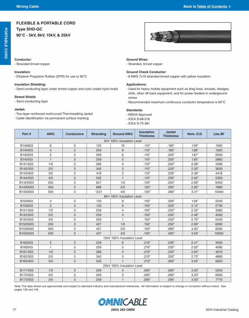
77
PO
RTA
BL
E C
OR
D
(800) 292-OMNI 2014 Industrial Catalog
Conductor:- Stranded tinned copper
Insulation:- Ethylene Propylene Rubber (EPR) for use to 90°C
Insulation Shielding:- Semi-conducting layer under tinned copper and color coded nylon braid
Strand Shield:- Semi-conducting layer
Jacket:- Two-layer reinforced mold-cured Thermosetting Jacket- Cable Identification via permanent surface marking
Ground Wires:- Stranded, tinned copper
Ground Check Conductor:- 8 AWG 7x19 stranded tinned copper with yellow insulation
Applications:- Used for heavy mobile equipment such as drag lines, shovels, dredges,
drills, other off track equipment, and for power feeders in underground mines
- Recommended maximum continuous conductor temperature is 90°C
Standards:- MSHA Approved- ICEA S-68-516- ICEA S-75-381
FLEXIBLE & PORTABLE CORD
Type SHD-GC
90°C - 5kV, 8kV, 15kV, & 25kV
Note: The data shown are approximate and subject to standard industry and manufacturer tolerances. All information is subject to change or correction without notice. See pages 139 and 140.
Part # AWG Conductors Stranding Ground AWGInsulation Thickness
Jacket Thickness
Nom. O.D. Lbs./M’
5kV 100% Insulation LevelB140603 6 3 133 10 .110” .185” 1.56” 1560 B140403 4 3 259 8 .110” .185” 1.68” 1920 B140203 2 3 259 6 .110” .205” 1.87” 2500 B140103 1 3 259 5 .110” .205” 1.95” 2860 B141/003 1/0 3 266 4 .110” .220” 2.08” 3390 B142/003 2/0 3 342 3 .110” .220” 2.20” 3830 B143/003 3/0 3 418 2 .110” .235” 2.36” 4418 B144/003 4/0 3 532 1 .110” .235” 2.50” 5300 B1425003 250 3 627 1/0 .120” .250” 2.69” 6450 B1435003 350 3 888 2/0 .120” .265” 2.95” 7880 B1450003 500 3 1221 4/0 .120” .280” 3.31” 10440
8kV 100% Insulation LevelB150403 4 3 133 8 .150” .205” 1.94” 2240 B150203 2 3 133 6 .150” .220” 2.12” 2730 B151/003 1/0 3 259 4 .150” .220” 2.32” 3380 B152/003 2/0 3 259 3 .150” .235” 2.46” 4030 B154/003 4/0 3 259 1 .150” .250” 2.75” 5440 B1525003 250 3 427 1/0 .150” .250” 2.89” 6280 B1535003 350 3 427 2/0 .150” .280” 3.20” 8300 B1550003 500 3 427 4/0 .150” .295” 3.56” 12000
15kV 100% Insulation LevelB160203 2 3 259 6 .210” .235” 2.41” 3500 B160103 1 3 259 5 .210” .235” 2.52” 4080 B161/003 1/0 3 266 4 .210” .250” 2.64” 4610 B162/003 2/0 3 342 3 .210” .250” 2.73” 4890 B163/003 3/0 3 532 1 .210” .265” 3.05” 6820
25kV 100% Insulation LevelB171/003 1/0 3 259 4 .295” .265” 3.05” 5250 B172/003 2/0 3 259 3 .295” .280” 3.20” 6000 B173/003 3/0 3 259 1 .295” .295” 3.50” 7710
Mining Cable Back to Table of Contents >

78
PO
RTA
BL
E C
OR
D
(800) 292-OMNI2014 Industrial Catalog
Conductor:- Extra flexible, stranded bare annealed copper
Grounding Conductor:- Coated copper. Class B strand. Two conductors, one laid in each of the
two remaining interstices
Insulation:- Natural ethylene propylene rubber (EPR)
Extruded Stranded Shield:- Extruded conducting stress control layer over strand
Extruded Insulation Shield:- Extruded conducting layer covered by an overlapped coated annealed
copper tape. A color coded (black, white, and red) marker stripe is placed under the copper tape
Jacket:- Yellow Chlorinated Polyethylene (CPE)
Applications:- For heavy duty high voltage portable power applications on mobile
equipment where delivery of a heavy power load is required, such as shovels, drudges, and underground mine power distribution
Standards:- Conforms to ICEA S-68-516 (NEMA WC8)- Temperature ratings:
- Normal Continuous - 90°C - Emergency - 130°C - Short Circuit - 250°C
Features:- EPR insulation provides excellent heat, moisture, corona, chemical, and
radiation resistance, flexibility for easy handling, high dielectric strength, electrical stability under stress, and low dielectric loss
- Coated copper tape provides an effective path to ground for electrical stresses, virtually eliminates the possibility of phase to phase faults and protects against shock hazard.
- Jacket is compounded for mining service, tough and reliable, and highly resistant to tearing, punctures, abrasions, oil, and flame.
FLEXIBLE & PORTABLE CORD
Type MP-GC - Grounded
90°C - 5kV & 8kV
Note: The data shown are approximate and subject to standard industry and manufacturer tolerances. All information is subject to change or correction without notice. See pages 139 and 140.
Part # AWG Stranding Insulation Thickness
Ground Check AWG
Grd. Cond. Stranding
Jacket Thickness
Nom. O.D. Lbs./M’
5kV 100% Insulation Level (Grounded)
B180603 6 7 .090” 8 7 .110” 1.21” 940
B180403 4 7 .090” 7 7 .110” 1.32” 1135
B180203 2 7 .090” 5 7 .110” 1.45” 1530
B181/003 1/0 19 .090” 3 7 .110” 1.63” 2150
B182/003 2/0 19 .090” 2 7 .140” 1.74” 2660
B184/003 4/0 19 .090” 1/0 19 .140” 2.00” 3870
B1825003 250 37 .090” 1/0 19 .140” 2.13” 4495
B1835003 350 37 .090” 2/0 19 .140” 2.35” 5850
B1850003 500 37 .090” 4/0 19 .170” 2.64” 8075
8kV 100% Insulation Level (Grounded)
B190603 6 7 .115” 10 7 .110” 1.33” 1050
B190403 4 7 .115” 8 7 .110” 1.43” 1265
B190203 2 7 .115” 6 7 .110” 1.55” 1690
B190103 1 19 .115” 5 7 .110” 1.65” 2020
B191/003 1/0 19 .115” 4 7 .110” 1.75” 2330
B192/003 2/0 19 .115” 3 7 .140” 1.88” 2875
B193/003 3/0 19 .115” 1 19 .140” 2.00” 3325
B194/003 4/0 19 .115” 1/0 19 .140” 2.12” 4070
B1925003 250 37 .115” 1/0 19 .140” 2.25” 4810
B1935003 350 37 .115” 2/0 19 .140” 2.46” 6430
B1950003 500 37 .115” 4/0 19 .170” 2.75” 8640
Mining Cable Back to Table of Contents >

79
PO
RTA
BL
E C
OR
D
(800) 292-OMNI 2014 Industrial Catalog
Conductor:- Annealed stranded bare copper
Insulation:- Cross-linked Polyethylene (XLPE)- Insulation shielded with extruded semi-conducting compound bare
copper tape
Grounding:- 2 ground wires- Ground wires are class B strands uninsulated, annealed stranded bare
copper- Ground check has annealed stranded bare copper, separator, and
yellow Cross-Linked Polyethylene (XLPE) insulation
Applications:- Designed for use in high voltage distribution circuits for permanent (or
semi-portable) installations in bore holes, shafts, open pits, strip mines, and tunnels
Standards:- MSHA Approved (P-136-MSHA)- Passes MSHA flame test- Meets ICEA requirements- UL listed under file no. E18966- OSHA acceptable- Built with flame retardant components- Excellent heat and moisture resistance- Resistant to most oils and chemicals
FLEXIBLE & PORTABLE CORD
Type MP-GC - Grounded
90°C - 15kV
Note: The data shown are approximate and subject to standard industry and manufacturer tolerances. All information is subject to change or correction without notice. See pages 139 and 140.
Part # AWG Size Conductors Stranding Ground AWG Ground
Check AWG Insulation Thickness
Nom. O.D. Lbs./M’
B450203 2 3 7 6 8 .175” 1.875” 2117
B450103 1 3 19 5 8 .175” 1.941” 2477
B451/003 1/0 3 19 4 8 .175” 2.025” 2742
B452/003 2/0 3 19 3 8 .175” 2.11” 3130
B454/003 4/0 3 19 1 8 .175” 2.33” 4385
B4525003 250 3 37 1/0 8 .175” 2.450” 5400
B4535003 350 3 37 2/0 8 .175” 2.700” 6730
B4550003 500 3 37 4/0 8 .175” 3.050” 8515
Color Code Chart:
Cond. Num. Color Cond. Num. Color
1 Black 2 White
3 Red
Mining Cable Back to Table of Contents >

80
BE
LD
EN
VF
D
(800) 292-OMNI2014 Industrial Catalog
VARIABLE FREQUENCY DRIVE CABLE
Classic Foil/Braid Design
Full-size Insulated Ground
600 Volt
††Final put-up may vary ± 10% from length shown.
Note: The data shown are approximate and subject to standard industry and manufacturer tolerances. All information is subject to change or correction without notice. See pages 139 and 140.
Insulation:- Three Stranded Tinned Copper(TC)
Circuit Conductors with XLPE Insulation
Ground:- One Full-sized Insulated Ground
(Same AWG as Circuit Conductors)
Shield:- Overall Duofoil® Shield + 85% TC Braid
plus full size TC Drain Wire
Specifications:- 1000V UL Flexible Motor Supply- 600V UL 1277 Type TC-ER per 2005
NEC Article 336- 1000V UL 2277 Type WTTC- 1000VCSAAWMI/IIA/BFT4- IEEE1202/383- ULDirectBurial- XHHW-2, RHW-2 rated circuit
conductors - 14AWG and larger- 90ºC Wet/Dry- Suitable for Class I, II & III, Division 2
hazardous locations- MSHA- UL 1685 Vertical Tray Flame Test- RoHS compliant- CE approved- C(UL) 600V Type CIC TC
Part # AWG Stranding Lbs./M’ Nom. O.D.Max. Pull
Tension (lbs.)Min. Bend
Radius
29500 16 26x30 185 0.53” 128 4.3”
29501 14 41x30 235 0.60” 212 4.8”
29502 12 65x30 298 0.65” 336 5.2”
29503 10 105x30 396 0.69” 592 5.5”
29504 8 7x19x29 680 0.93” 768 7.5”
29505 6 7x19x27 906 1.02” 1220 8.2”
29506 4 7x19x25 1227 1.16” 1940 9.3”
29507 2 7x19x23 1766 1.31” 3088 10.8”
Variable Frequency Drive Cable Back to Table of Contents >

81
BE
LD
EN
VF
D
(800) 292-OMNI 2014 Industrial Catalog
VARIABLE FREQUENCY DRIVE CABLE
Classic Foil/Braid Design
Full-size Insulated Ground
2000 Volt
Insulation:- Three Stranded Tinned Copper
(TC) Circuit Conductors with XLPE Insulation
Ground:- One Full-sized Insulated Ground
(Same AWG as Circuit Conductors)
Shield:- Overall Duofoil Shield + 85% TC Braid
Shield plus full size TC Drain Wire
Jacket:- Black Sunlight- and Oil-Resistant
Polyvinyl Chloride (PVC) Jacket
Specifications:- 1000V UL Flexible Motor Supply- 2000V UL 1277 Type TC-ER per 2005
NEC Article 336- 1000V UL 2277 Type WTTC- 1000V CSA AWM I/II A/B FT4- IEEE 1202/383- UL Direct Burial- XHHW-2, RHW-2 rated circuit
conductors- 90ºC Wet/Dry- Suitable for Class I, II & III, Division 2
hazardous locations- UL 1685 Vertical Tray Flame Test- RoHS compliant- C(UL) 600V Type CIC TC
†Final put-up may vary ± 10% from length shown.
Note: The data shown are approximate and subject to standard industry and manufacturer tolerances. All information is subject to change or correction without notice. See pages 139 and 140.
Part # AWG Stranding Lbs./M’ Nom. O.D.Max. Pull
Tension (lbs.)Min. Bend
Radius
29536 14 41x30 338 0.68” 212 6.8”
29537 12 65x30 401 0.72” 336 7.3”
29538 10 105x30 481 0.79” 592 7.9”
29539 8 7x19x29 754 0.96” 768 9.6”
29540 6 7x19x27 926 1.07” 1220 10.6”
29541 4 7x19x25 1284 1.21” 1940 12.1”
29542 2 7x19x23 1756 1.36” 3088 13.6”
Variable Frequency Drive Cable Back to Table of Contents >

82
BE
LD
EN
VF
D
(800) 292-OMNI2014 Industrial Catalog
VARIABLE FREQUENCY DRIVE CABLE
Classic Foil/Braid Design with Signal Pair
Full-size Insulated Ground
600 Volt
††Final put-up may vary ± 10% from length shown.
Note: The data shown are approximate and subject to standard industry and manufacturer tolerances. All information is subject to change or correction without notice. See pages 139 and 140.
Insulation:- Three Stranded Tinned Copper
(TC) Circuit Conductors with XLPE Insulation
Ground:- One Full-sized Insulated Ground
(Same AWG as Circuit Conductors)
Shield:- Overall Duofoil Shield + 85% TC Braid
plus full size TC Drain Wire
Signal Pair:- One 16 AWG Shielded Signal Pair for
Brake with Drain Wire
Jacket:Black Sunlight- and Oil-Resistant
Polyvinyl Chloride (PVC) Jacket
Specifications:- 1000V UL Flexible Motor Supply- 600V UL 1277 Type TC-ER per 2005
NEC Article 336- 1000V CSA AWM I/II A/B FT4- IEEE 1202/383- UL Direct Burial- XHHW-2, RHW-2 rated circuit
conductors -14 AWG and larger- 90ºC Wet/Dry- Suitable for Class I, II & III, Division 2
hazardous locations- MSHA- UL 1685 Vertical Tray Flame Test- RoHS compliant- CE approved- C(UL) 600V Type CIC TC
Part #AWG
Stranding Lbs./M’Nom. O.D.
Max. Pull Tension (lbs.)
Min. Bend RadiusCircuit
Cond.Signal
Pair
29510 16 16 26x30 324 0.75” 272 7.5”
29511 14 16 26x30 340 0.82” 368 8.2”
29512 12 16 26x30 438 0.90” 527 9.0”
29513 10 16 26x30 563 0.99” 718 9.9”
Variable Frequency Drive Cable Back to Table of Contents >

83
BE
LD
EN
VF
D
(800) 292-OMNI 2014 Industrial Catalog
VARIABLE FREQUENCY DRIVE CABLE
Classic Foil/Braid Design
Full-size Insulated Ground
Low Smoke Zero Halogen
600 Volt
Insulation:- Three Stranded Tinned Copper (TC)
Circuit Conductors with XLPE Insulation
Ground:- One Full-sized Insulated Ground
(Same AWG as Circuit Conductors)
Shield:- Overall Duofoil Shield + 85% TC Braid
plus full size TC Drain Wire
Jacket:- Black Sunlight-Resistant Haloarrest
Jacket
Specifications:- 1000V UL Flexible Motor Supply- 600V UL 1277 Type TC-ER per 2005
NEC Article 336- 1000V UL 2277 Type WTTC- 1000V CSA AWM I/II A/B FT4- IEEE 1202/383- UL Direct Burial- XHHW-2, RHW-2 rated circuit
conductors -14 AWG and larger- 90º C Wet/Dry- Suitable for Class I, II & III, Division 2
hazardous locations- MSHA- UL 1685 Vertical Tray Flame Test- RoHS compliant- CE approved
†Final put-up may vary ± 10% from length shown.
Note: The data shown are approximate and subject to standard industry and manufacturer tolerances. All information is subject to change or correction without notice. See pages 139 and 140.
Part # AWG Stranding Lbs./M’ Nom. O.D.Max. Pull
Tension (lbs.)Min. Bend
Radius
29500T 16 26x30 191 0.53” 128 4.3”
29501T 14 41x30 243 0.60” 212 4.8”
29502T 12 65x30 306 0.65” 336 5.2”
29503T 10 105x30 405 0.69” 592 5.5”
29504T 8 7x19x29 696 0.93” 768 7.5”
29505T 6 7x19x27 924 1.02” 1220 8.2”
29506T 4 7x19x25 1248 1.16” 1940 9.3”
29507T 2 7x19x23 1789 1.31” 3088 10.8”
Variable Frequency Drive Cable Back to Table of Contents >

84
BE
LD
EN
VF
D
(800) 292-OMNI2014 Industrial Catalog
VARIABLE FREQUENCY DRIVE CABLE
Classic Symmetrical Design
Large AWG
600 Volt
Insulation:- Three Stranded Tinned Copper
(TC) Circuit Conductors with XLPE Insulation
Ground:- Three Symmetrical Bare Copper (BC)
Grounds
Shield:- Two Spiral Copper Tape Shields (100%
Coverage)
Jacket:- Black Sunlight- and Oil-Resistant
Polyvinyl Chloride (PVC) Jacket
Specifications:- 1000V UL Flexible Motor Supply- 600V UL 1277 Type TC-ER per 2005
NEC Article 336- 1000V UL 2277 Type WTTC- 1000V CSA AWM I/II A/B FT4- IEEE 1202/383- UL Direct Burial- XHHW-2 rated circuit conductors- 90˚C Wet/Dry- Suitable for Class I, II & III, Division 2
hazardous locations- MSHA- UL 1685 Vertical Tray Flame Test- RoHS compliant- CE approved- C(UL) 600V Type RW90 TC
†Final put-up may vary ± 5% from length shown.
Note: The data shown are approximate and subject to standard industry and manufacturer tolerances. All information is subject to change or correction without notice. See pages 139 and 140.
Part # AWG Stranding Lbs./M’ Nom. O.D.Max. Pull
Tension (lbs.)Min. Bend
Radius
29528 1 7x19x22 1610 1.20” 2650 12.0”
29529 1/0 7x19x21 2013 1.29” 3537 12.9”
29530 2/0 7x19x20 2318 1.40” 4200 14.0”
29531 3/0 7x19x19 2708 1.52” 5025 15.2”
29532 4/0 7x19x18 1717 1.68” 6670 16.8”
Variable Frequency Drive Cable Back to Table of Contents >

85
BE
LD
EN
VF
D
(800) 292-OMNI 2014 Industrial Catalog
VARIABLE FREQUENCY DRIVE CABLE
Classic Symmetrical Design
Large AWG
2000 Volt
Insulation:- Three Stranded Tinned Copper (TC)
Circuit Conductors with XLPE Insulation
Ground:- Three Symmetrical Bare Copper
(BC) Grounds
Shield:- Two Spiral Copper Tape Shields
(100% Coverage)
Jacket:- Black Sunlight- and Oil-Resistant
Polyvinyl Chloride (PVC) Jacket
Specifications:- 1000V UL Flexible Motor Supply- 2000V UL 1277 Type TC-ER per 2005
NEC Article 336- 1000V UL 2277 Type WTTC- 1000V CSA AWM I/II A/B FT4- IEEE 1202/383- UL Direct Burial- XHHW-2, RHW-2 rated circuit
conductors- 90ºC Wet/Dry- Suitable for Class I, II & III, Division 2
hazardous locations- UL 1685 Vertical Tray Flame Test- RoHS compliant- CE approved- 1 AWG through 4/0 are C(UL) 600V
Type RW90 TC
†Final put-up may vary ± 5% from length shown.
*250 MCM and larger use bare copper conductors
Note: The data shown are approximate and subject to standard industry and manufacturer tolerances. All information is subject to change or correction without notice. See pages 139 and 140.
Part # AWG Stranding Lbs./M’ Nom. O.D.Max. Pull
Tension (lbs.)Min. Bend
Radius
29543 1 7x19x22 1693 1.36” 2650 13.6”
29544 1/0 7x19x21 2056 1.45” 3537 14.5”
29545 2/0 7x19x20 2389 1.56” 4200 15.6”
29546 3/0 7x19x19 2989 1.75” 5025 17.5”
29547 4/0 7x19x18 3264 1.88” 6670 18.8”
29533* 250 MCM 37X.0822 4077 1.91” 6000 34.4”
29534* 350 MCM 37X.0973 5486 2.13” 8400 38.4”
29535* 500 MCM 37X.1162 7364 2.41” 12000 43.4”
Variable Frequency Drive Cable Back to Table of Contents >

86
BE
LD
EN
VF
D
(800) 292-OMNI2014 Industrial Catalog
VARIABLE FREQUENCY DRIVE CABLE
Classic Symmetrical Design
Large AWG
Low Smoke Zero Halogen
600 Volt
Insulation:- Three Stranded Tinned Copper
(TC) Circuit Conductors with XLPE Insulation
Ground:- Three Symmetrical Bare Copper
(BC) Grounds
Shield:- Two Spiral Copper Tape Shields
(100% Coverage)
Jacket:- Black Sunlight-Resistant Haloarrest
Jacket
Specifications:- 1000V UL Flexible Motor Supply- 600V UL 1277 Type TC-ER per 2005
NEC Article 336- 1000V UL 2277 Type WTTC- 1000V CSA AWM I/II A/B FT4- IEEE 1202/383- UL Direct Burial- XHHW-2 rated circuit conductors- 90º C Wet/Dry- Suitable for Class I, II & III, Division 2
hazardous locations- MSHA- UL 1685 Vertical Tray Flame Test- RoHS compliant- CE approved
†Final put-up may vary ± 5% from length shown.
Note: The data shown are approximate and subject to standard industry and manufacturer tolerances. All information is subject to change or correction without notice. See pages 139 and 140.
Part # AWG Stranding Lbs./M’ Nom. O.D.Max. Pull
Tension (lbs.)Min. Bend
Radius
29528T 1 7x19x22 1621 1.20” 2650 12.0”
29529T 1/0 7x19x21 2025 1.29” 3537 12.9”
29530T 2/0 7x19x20 2331 1.40” 4200 14.0”
29531T 3/0 7x19x19 2722 1.52” 5025 15.2”
29532T 4/0 7x19x18 1725 1.68” 6670 16.8”
Variable Frequency Drive Cable Back to Table of Contents >

87
BE
LD
EN
VF
D
(800) 292-OMNI 2014 Industrial Catalog
VARIABLE FREQUENCY DRIVE CABLE
Symmetrical Design
Basics
600 Volt
Insulation:- Three Stranded Bare Copper (BC)
Circuit Conductors with XLPE Insulation
Ground:- Three Symmetrical Bare Copper (BC)
Grounds
Shield:- Two Spiral Copper Tape Shields
(100% Coverage)
Jacket:- Black Sunlight- and Oil-Resistant
Polyvinyl Chloride (PVC) Jacket
Specifications:- 600V UL 1277 Type TC-ER per 2005
NEC Article 336- 1000V CSA AWM I/II A/B FT4- IEEE 1202/383- UL Direct Burial- XHHW-2 rated circuit conductors –
14 AWG and larger- 90ºC Wet/Dry- Suitable for Class I, II & III, Division 2
hazardous locations- UL 1685 Vertical Tray Flame Test- RoHS compliant- CE approved
†Final put-up may vary ± 5% from length shown.
Note: The data shown are approximate and subject to standard industry and manufacturer tolerances. All information is subject to change or correction without notice. See pages 139 and 140.
Part # AWG Stranding Lbs./M’ Nom. O.D.Max. Pull
Tension (lbs.)Min. Bend
Radius
29520C 16 7x24 122 0.39” 107 4.0”
29521C 14 7x22 142 0.43” 162 4.3”
29522C 12 7x20 182 0.46” 258 4.6”
29523C 10 7x18 274 0.51” 444 5.1”
29524C 8 7x16 425 0.65” 576 6.5”
29525C 6 7x14 553 0.72” 915 7.3”
29526C 4 7x12 602 0.83” 1450 8.3”
29527C 2 7x10 1105 0.99” 2300 10.0”
29528C 1 7x19x22 1314 1.13” 2650 11.5”
29529C 1/0 7x19x21 1590 1.21” 3537 12.3”
29530C 2/0 7x19x20 1885 1.31” 4200 13.3”
29531C 3/0 7x19x19 2301 1.42” 5025 14.3”
29532C 4/0 7x19x18 1420.5 1.54” 6670 15.5”
Variable Frequency Drive Cable Back to Table of Contents >

88
BE
LD
EN
VF
D
(800) 292-OMNI2014 Industrial Catalog
VARIABLE FREQUENCY DRIVE CABLE
Classic Foil/Braid & Symmetrical
Interlocked Armor
600 Volt
Jacket:- Black Sunlight- and Oil-Resistant
Polyvinyl Chloride (PVC) Jacket
Armor: - Interlocked Armor
Specifications:- 600V UL 1277 Type MC per 2005
NEC Article 330- CSA FT4- UL Direct Burial- XHHW-2, RHW-2 rated circuit
conductors (16 to 2 AWG)- XHHW-2 rated circuit conductors
(1 to 4/0 AWG)- 90ºC Wet/Dry- Suitable for Class I & II, Division 2
hazardous locations- IEEE 1202/383- RoHS compliant- CE approved
†Final put-up may vary ± 5% from length shown.
Note: The data shown are approximate and subject to standard industry and manufacturer tolerances. All information is subject to change or correction without notice. See pages 139 and 140.
AWG AL Armor Part # Steel Armor Part #
16 1229500 1329500
14 1229501 1329501
12 1229502 1329502
10 1229503 1329503
8 1229504 1329504
6 1229505 1329505
4 1229506 1329506
2 1229507 1329507
1 1229528 1329528
1/0 1229529 1329529
2/0 1229530 1329530
3/0 1229531 1329531
4/0 1229532 1329532
Variable Frequency Drive Cable Back to Table of Contents >

89
MA
RIN
E C
AB
LE
(800) 292-OMNI 2014 Industrial Catalog
Conductor:- Soft annealed tinned copper flexible
strand
Insulation: - Cross-Linked Polyolefin (XLPO)- Color Code: Per IEEE 1580 Table 22
Cable Core:- Cabled with fillers when required- Core binder tape when required
Sheath:- Mud Oil-resistant, Black Cross-Linked
Chlorosulfonated Polyethylene
Applications:- Offshore oil and gas drilling platforms,
MODUs, ships and FPSOs- Land-based oil and gas drilling rigs- Suitable for use in Class I, Division 2 and
Zone 2 environments
Features:- Meets NEK 606 mud oil resistance
requirements including ester-based muds- Meets UL 2225 crush and impact
requirements of Type MC-HL cables- Permitted for Exposed Run “ER” (open
wiring) use in accordance with NEC for 3 conductors or more
- Flexible stranding to facilitate ease of cable installation and termination
- Meets cold bend test at -55°C- Meets cold impact test at -40°C
Compliances:Industry:- API-RP14F- CSA C22.2 No. 245 Type X110- IEEE 1580 Type P- IEC 60092-3- NEK 606 for mud oil resistance- UL 1309 Type X110- UL Listed 110°C Marine Shipboard CableFlame Test:- IEEE 383- IEEE 1202- IEC 60332-3-22 Cat. A (supersedes IEC
60332-3A)- CSA C22.2 No. 0.3 FT4
MARINE CABLE
Unarmored Type P
Flexible Multi Conductor Power
600 V/1000 V
18 AWG & 16 AWG
Note: The data shown are approximate and subject to standard industry and manufacturer tolerances. All information is subject to change or correction without notice. See pages 139 and 140.
Part # AWG Conductors Nom. O.D. Lbs./M’
TP11802 18 2 .355” 65
TP11803 18 3 .373” 80
TP11804 18 4 .400” 97
TP11805 18 5 .432” 115
TP11806 18 6 .465” 133
TP11807 18 7 .465” 146
TP11808 18 8 .500” 164
TP11810 18 10 .575” 203
TP11812 18 12 .593” 232
TP11816 18 16 .652” 293
TP11820 18 20 .719” 357
TP11824 18 24 .792” 410
TP11830 18 30 .875” 494
TP11837 18 37 .945” 646
TP11844 18 44 1.055” 765
TP11860 18 60 1.165” 998
TP11891 18 91 1.385” 1458
TP11602 16 2 .367” 69
TP11603 16 3 .386” 86
TP11604 16 4 .415” 105
TP11605 16 5 .448” 125
TP11606 16 6 .483” 145
TP11607 16 7 .483” 159
TP11608 16 8 .519” 179
TP11610 16 10 .599” 222
TP11612 16 12 .618” 254
TP11616 16 16 .647” 288
TP11620 16 20 .751” 393
TP11624 16 24 .831” 467
TP11630 16 30 .924” 473
TP11637 16 37 .987” 712
TP11644 16 44 1.104” 846
TP11660 16 60 1.220” 1155
TP11691 16 91 1.485” 1659
Type P Back to Table of Contents >

90
MA
RIN
E C
AB
LE
(800) 292-OMNI2014 Industrial Catalog
Conductor:- Soft annealed tinned copper flexible
strand
Insulation:- Cross-Linked Polyolefin (XLPO)- Color Code: Per IEEE 1580 Table 22
Cable Core:- Cabled with fillers when required- Core binder tape when required
Sheath:- Mud Oil-resistant, Black Cross-Linked
Chlorosulfonated Polyethylene
Applications:- Offshore oil and gas drilling platforms,
MODUs, ships and FPSOs- Land-based oil and gas drilling rigs- Suitable for use in Class I, Division 2 and
Zone 2 environments
Features:- Meets NEK 606 mud oil resistance
requirements including ester-based muds- Meets UL 2225 crush and impact
requirements of Type MC-HL cables- Permitted for Exposed Run “ER” (open
wiring) use in accordance with NEC for 3 conductors or more
- Flexible stranding to facilitate ease of cable installation and termination
- Meets cold bend test at -55°C- Meets cold impact test at -40°C
Compliances:Industry:- API-RP14F- CSA C22.2 No. 230 Type TC- CSA C22.2 No. 245 Type X110- IEEE 1580 Type P- IEC 60092-3- NEK 606 for mud oil resistance- UL 1309 Type X110- UL Listed 110°C Marine Shipboard CableFlame Test:- IEEE 383- IEEE 1202- IEC 60332-3-22 Cat. A (supersedes IEC
60332-3A)- CSA C22.2 No. 0.3 FT4
MARINE CABLE
Unarmored Type P
Flexible Multi Conductor Power
600 V/1000 V
14 AWG - 10 AWG
Note: The data shown are approximate and subject to standard industry and manufacturer tolerances. All information is subject to change or correction without notice. See pages 139 and 140.
Part # AWG Conductors Nom. O.D. Lbs./M’
TP11402 14 2 .395” 85TP11403 14 3 .415” 107TP11404 14 4 .455” 136TP11405 14 5 .490” 161TP11406 14 6 .530” 181TP11407 14 7 .530” 208TP11408 14 8 .575” 237TP11410 14 10 .660” 290TP11412 14 12 .690” 340TP11414 14 14 .670” 352TP11416 14 16 .790” 449TP11420 14 20 .825” 530TP11424 14 24 .957” 669TP11430 14 30 1.040” 814TP11437 14 37 1.105” 964TP11444 14 44 1.255” 1163TP11460 14 60 1.390” 1529TP11491 14 91 1.740” 2377TP11202 12 2 .435” 110TP11203 12 3 .460” 143TP11204 12 4 .495” 178TP11205 12 5 .550” 220TP11206 12 6 .585” 252TP11207 12 7 .585” 281TP11208 12 8 .635” 321TP11210 12 10 .735” 397TP11212 12 12 .740” 492TP11216 12 16 .845” 532TP11220 12 20 .985” 777TP11224 12 24 1.090” 792TP11230 12 30 1.150” 986TP11237 12 37 1.240” 1346TP11244 12 44 1.395” 1395TP11260 12 60 1.570” 2155TP11291 12 91 1.975” 2828TP11002 10 2 .495” 154TP11003 10 3 .520” 203TP11004 10 4 .570” 260TP11005 10 5 .630” 320TP11006 10 6 .675” 371TP11007 10 7 .675” 418TP11008 10 8 .730” 474TP11010 10 10 .915” 642TP11012 10 12 .945” 743
Type P Back to Table of Contents >

91
MA
RIN
E C
AB
LE
(800) 292-OMNI 2014 Industrial Catalog
Conductor:- Soft annealed tinned copper flexible
strand
Insulation:- Cross-Linked Polyolefin (XLPO) - Black- Heavy-Duty (HD) Cross-Linked Polyolefin
(XLPO) - 4/0 and larger - Black
Sheath:- Mud Oil-resistant, Black Cross-Linked
Chlorosulfonated Polyethylene
Applications:- Offshore oil and gas drilling platforms,
MODUs, ships and FPSOs- Land-based oil and gas drilling rigs- Suitable for use in Class I, Division 2 and
Zone 2 environments
Features:- Meets NEK 606 mud oil resistance
requirements including ester-based muds- Flexible stranding to facilitate ease of
cable installation and termination- Meets cold bend test at -55°C- Meets cold impact test at -40°C
Compliances:Industry:- API-RP14F- CSA C22.2 No. 245 Type X110- IEEE 1580 Type P- IEC 60092-3- NEK 606 for mud oil resistance- UL 1309 Type X110- UL Listed 110°C Marine Shipboard Cable
Flame Test:- IEEE 383- IEEE 1202- IEC 60332-3-22 Cat. A (supersedes IEC
60332-3A)- CSA C22.2 No. 0.3 FT4
MARINE CABLE
Unarmored Type P
Flexible Power
2000 V/1000 V
Single Conductor
* 2 kV/1000 V - 3/0 AWG and smaller constructions with Regular Duty insulation thickness
* 2 kV/1000 V Heavy-Duty - 4/0 AWG and larger constructions with Heavy-Duty (HD) insulation thickness
Note: The data shown are approximate and subject to standard industry and manufacturer tolerances. All information is subject to change or correction without notice. See pages 139 and 140.
Part # AWG Conductors Nom. O.D. Lbs./M’
TP10801 8 1 .380” 103
TP10601 6 1 .420” 143
TP10501 5 1 .485” 198
TP10401 4 1 .500” 232
TP10301 3 1 .540” 267
TP10201 2 1 .550” 300
TP10101 1 1 .640” 432
TP11/001 1/0 1 .700” 542
TP12/001 2/0 1 .720” 563
TP13/001 3/0 1 .810” 743
TP14/001 4/0 1 1.005” 1012
TP126201 262 1 1.040” 1181
TP131301 313 1 1.110” 1383
TP137301 373 1 1.185” 1856
TP144401 444 1 1.250” 1894
TP153501 535 1 1.345” 2188
TP164601 646 1 1.460” 2624
TP177701 777 1 1.540” 3129
TP1111101 1111 1 1.810” 4270
Type P Back to Table of Contents >

92
MA
RIN
E C
AB
LE
(800) 292-OMNI2014 Industrial Catalog
Part # AWG Conductors Nom. O.D. Lbs./M’
TP10802 8 2 .594” 240
TP10602 6 2 .672” 362
TP10502 5 2 .790” 455
TP10402 4 2 .830” 540
TP10302 3 2 .935” 625
TP10202 2 2 1.005” 675
TP10102 1 2 1.171” 1045
TP11/002 1/0 2 1.269” 1240
TP12/002 2/0 2 1.345” 1545
TP13/002 3/0 2 1.559” 1845
TP14/002 4/0 2 1.685” 2330
TP126202 262 2 1.795” 2640
TP1313202 313 2 1.935” 3156
TP144402 444 2 2.280” 3656
TP153502 535 2 2.580” 4503
TP164602 646 2 2.874” 5673
TP177702 777 2 3.044” 6681
TP10803 8 3 .641” 305
TP10603 6 3 .725” 433
TP10503 5 3 .893” 642
TP10403 4 3 .936” 730
TP10303 3 3 .990” 840
TP10203 2 3 1.066” 935
TP10103 1 3 1.245” 1424
TP11/003 1/0 3 1.351” 1682
TP12/003 2/0 3 1.473” 2027
TP13/003 3/0 3 1.681” 2670
TP14/003 4/0 3 1.825” 3210
TP126203 262 3 1.966” 3660
TP131303 313 3 2.117” 4347
TP137303 373 3 2.257” 5010
TP144403 444 3 2.460” 6025
TP153503 535 3 2.681” 7195
TP164603 646 3 2.914” 8450
TP177703 777 3 3.090” 10325
Conductor:- Soft annealed tinned copper flexible
strand
Insulation:- Cross-Linked Polyolefin (XLPO)- Color Code: Per IEEE 1580 Table 22
Cable Core:- Cabled with fillers when required- Core binder tape when required
Sheath:- Mud Oil-resistant, Black Cross-Linked
Chlorosulfonated Polyethylene
Applications:- Offshore oil and gas drilling platforms,
MODUs, ships and FPSOs- Land-based oil and gas drilling rigs- Suitable for use in Class I, Division 2 and
Zone 2 environments
Features:- Meets NEK 606 mud oil resistance
requirements including ester-based muds- Meets UL 2225 crush and impact
requirements of Type MC-HL cables- Permitted for Exposed Run “ER” (open
wiring) use in accordance with NEC for 3 conductors or more
- Flexible stranding to facilitate ease of cable installation and termination
- Meets cold bend test at -55°C- Meets cold impact test at -40°C
Compliances:Industry:- API-RP14F- CSA C22.2 No. 230 Type TC- CSA C22.2 No. 245 Type X110- IEEE 1580 Type P- IEC 60092-3- NEK 606 for mud oil resistance- UL 1309 Type X110- UL Listed 110°C Marine Shipboard CableFlame Test:- IEEE 383- IEEE 1202- IEC 60332-3-22 Cat. A (supersedes IEC
60332-3A)- CSA C22.2 No. 0.3 FT4
MARINE CABLE
Unarmored Type P
Flexible Multi Conductor Power
600 V/1000 V
2 & 3 Conductor
Note: The data shown are approximate and subject to standard industry and manufacturer tolerances. All information is subject to change or correction without notice. See pages 139 and 140.
Type P Back to Table of Contents >

93
MA
RIN
E C
AB
LE
(800) 292-OMNI 2014 Industrial Catalog
Conductor:- Soft annealed tinned copper flexible
strand
Insulation:- Cross-Linked Polyolefin (XLPO)- Color Code: Per IEEE 1580 Table 222
Cable Core:- Cabled with fillers when required- Core binder tape when required
Sheath:- Mud Oil-resistant, Black Cross-Linked
Chlorosulfonated Polyethylene
Applications:- Offshore oil and gas drilling platforms,
MODUs, ships and FPSOs- Land-based oil and gas drilling rigs- Suitable for use in Class I, Division 2 and
Zone 2 environments
Features:- Meets NEK 606 mud oil resistance
requirements including ester-based muds- Meets UL 2225 crush and impact
requirements of Type MC-HL cables- Permitted for Exposed Run “ER” (open
wiring) use in accordance with NEC for 3 conductors or more
- Flexible stranding to facilitate ease of cable installation and termination
- Meets cold bend test at -55°C- Meets cold impact test at -40°C
Compliances:Industry:- API-RP14F- CSA C22.2 No. 230 Type TC- CSA C22.2 No. 245 Type X110- IEEE 1580 Type P- IEC 60092-3- NEK 606 for mud oil resistance- UL 1309 Type X110- UL Listed 110°C Marine Shipboard CableFlame Test:- IEEE 383- IEEE 1202- IEC 60332-3-22 Cat. A (supersedes IEC
60332-3A)- CSA C22.2 No. 0.3 FT4
MARINE CABLE
Unarmored Type P
Flexible Multi Conductor Power
600 V/1000 V
4 & 5 Conductor
Note: The data shown are approximate and subject to standard industry and manufacturer tolerances. All information is subject to change or correction without notice. See pages 139 and 140.
Part # AWG Conductors Nom. O.D. Lbs./M’
TP10804 8 4 .699” 385
TP10604 6 4 .793” 555
TP10504 5 4 .975” 795
TP10404 4 4 1.024” 910
TP10304 3 4 1.084” 1075
TP10204 2 4 1.168” 1205
TP10104 1 4 1.368” 1830
TP11/004 1/0 4 1.486” 2140
TP12/004 2/0 4 1.638” 2565
TP13/004 3/0 4 1.877” 3360
TP14/004 4/0 4 2.005” 4020
TP126204 262 4 2.162” 4720
TP131304 313 4 2.331” 5520
TP137304 373 4 2.487” 6570
TP144404 444 4 2.710” 7975
TP153504 535 4 2.951” 9710
TP164604 646 4 2.914” 8450
TP177704 777 4 3.430” 13324
TP10805 8 5 .766” 475
TP10605 6 5 .912” 770
TP10505 5 5 1.071” 935
TP10405 4 5 1.125” 1095
TP10305 3 5 1.193” 1290
TP10205 2 5 1.287” 1520
TP10105 1 5 1.511” 2350
TP11/005 1/0 5 1.703” 2770
TP12/005 2/0 5 1.806” 3320
TP13/005 3/0 5 2.071” 4375
TP14/005 4/0 5 2.214” 5010
TP126205 262 5 2.404” 5534
TP131305 313 5 2.572” 6456
TP137305 373 5 2.705” 7555
TP144405 444 5 2.890” 8888
TP153505 535 5 3.190” 11247
Type P Back to Table of Contents >

94
MA
RIN
E C
AB
LE
(800) 292-OMNI2014 Industrial Catalog
Part # AWG Conductors Nom. O.D. Lbs./M’
TP20101 1 1 .698” 521
TP21/001 1/0 1 .747” 600
TP22/001 2/0 1 .785” 688
TP23/001 3/0 1 .912” 918
TP24/001 4/0 1 1.045” 1195
TP226201 262 1 1.090” 1290
TP231301 313 1 1.175” 1488
TP237301 373 1 1.240” 1710
TP244401 444 1 1.320” 2115
TP253501 535 1 1.460” 2565
TP264601 646 1 1.570” 2950
TP277701 777 1 1.685” 3497
TP2111101 1111 1 1.925” 9651
Conductor:- Soft annealed tinned copper flexible
strand
Insulation:- Cross-Linked Polyolefin (XLPO) - Black- Heavy-Duty (HD) Cross-Linked Polyolefin
(XLPO) - 4/0 and larger - black
Armor:- Bronze braid 88% minimum coverage
Sheath:- Mud Oil-Resistant, Black Cross-Linked
Chlorosulfonated Polyethylene
Applications:- Offshore oil and gas drilling platforms,
MODUs, ships and FPSOs- Land-based oil and gas drilling rigs- Suitable for use in Class I, Division 1,
and Zone 1 Hazardous Locations when installed in accordance with API RP14F
Standards:- Meets NEK 606 mud oil resistance
requirements including ester-based muds- Flexible stranding to facilitate ease of
cable installation and termination- Meets cold bend test at -55°C- Meets cold impact test at -40°C- API-RP14F- CSA C22.2 No. 245 Type X110- IEEE 1580 Type P- IEC 60092-3- NEK 606 for mud oil resistance- UL 1309 Type X110- UL Listed 110°C Marine Shipboard Cable- Flame Test: IEEE 383, IEEE 1202, IEC
60332-3-22 Cat. A (supersedes IEC 60332-3A), CSA C222.2 No. 0.3 FT4
MARINE CABLE
Armored & Sheathed Type P
Flexible Power
2000 V/1000 V
Single Conductor
* Sizes 3/0 and small constructions with Regular-Duty insulation thickness.
* Sizes 4/0 and larger constructions with Heavy-Duty (HD) insulation thickness.
Note: The data shown are approximate and subject to standard industry and manufacturer tolerances. All information is subject to change or correction without notice. See pages 139 and 140.
Armored Type P Back to Table of Contents >

95
MA
RIN
E C
AB
LE
(800) 292-OMNI 2014 Industrial Catalog
Conductor:- Soft annealed tinned copper flexible
strand
Insulation:- Cross-Linked Polyolefin (XLPO)- Color Code: per IEEE 1580 Table 22
Cable Core:- Cabled with fillers when required- Core binder tape when required
Sheath:- Black Cross-Linked Chlorosulfonated
Polyethylene- Mud Oil-Resistant, Black Cross-Linked
Chlorosulfonated Polyethylene
Armor:- Bronze braid 88% minimum coverage
Applications:- Offshore oil and gas drilling platforms,
MODUs, ships and FPSOs- Land-based oil and gas drilling rigs- Suitable for use in Class I, Division 1,
and Zone 1 Hazardous Locations when installed in accordance with API RP14F
Standards:- Meets NEK 606 mud oil resistance
requirements including ester-based muds- Meets UL 2225 crush and impact
requirements of Type MC-HL cables- Flexible stranding to facilitate ease of
cable installation and termination- Meets cold bend test at -55°C- Meets cold impact test at -40°C- API-RP14F- CSA C22.2 No. 245 Type X110- IEEE 1580 Type P- IEC 60092-3- NEK 606 for mud oil resistance- UL 1309 Type X110- UL Listed 110°C Marine Shipboard Cable- Flame Test: IEEE 383, IEEE 1202, IEC
60332-3-22 Cat. A (supersedes IEC 60332-3A), CSA C222.2 No. 0.3 FT4
MARINE CABLE
Armored & Sheathed Type P
Flexible Multi Conductor Power
600 V/1000 V
2 & 3 Conductor
Note: The data shown are approximate and subject to standard industry and manufacturer tolerances. All information is subject to change or correction without notice. See pages 139 and 140.
Part # AWG Conductors Nom. O.D. Lbs./M’
TP20802 8 2 .774” 457
TP20602 6 2 .892” 650
TP20502 5 2 1.010” 789
TP20402 4 2 1.050” 889
TP20302 3 2 1.155” 1015
TP20202 2 2 1.225” 1091
TP20102 1 2 1.391” 1525
TP21/002 1/0 2 1.489” 1758
TP22/002 2/0 2 1.565” 2093
TP23/002 3/0 2 1.839” 2615
TP24/002 4/0 2 1.945” 3149
TP24/002 4/0 2 1.945” 3149
TP226202 262 2 2.075” 3519
TP231302 313 2 2.215” 4100
TP237302 373 2 2.455” 4635
TP244402 444 2 2.650” 4822
TP253502 535 2 2.950” 5804
TP264602 646 2 3.245” 7114
TP277702 777 2 3.415” 8205
TP20803 8 3 .861” 581
TP20603 6 3 .945” 742
TP20503 5 3 1.128” 1037
TP20403 4 3 1.171” 1142
TP20303 4 3 1.225” 1247
TP20203 2 3 1.301” 1400
TP20103 1 3 1.480” 1961
TP21/003 1/0 3 1.646” 2387
TP22/003 2/0 3 1.768” 2791
TP23/003 3/0 3 2.006” 3611
TP24/003 4/0 3 2.180” 4310
TP226203 262 3 2.321” 4838
TP231303 313 3 2.472” 5610
TP237303 373 3 2.612” 6351
TP244403 444 3 2.815” 7480
TP253503 535 3 3.036” 8773
TP264603 646 3 3.285” 9915
TP277703 777 3 3.460” 11865
Armored Type P Back to Table of Contents >

96
MA
RIN
E C
AB
LE
(800) 292-OMNI2014 Industrial Catalog
Part # AWG Conductors Nom. O.D. Lbs./M’
TP20804 8 4 .919” 684
TP20604 6 4 1.013” 890
TP20504 5 4 1.210” 1223
TP20404 4 4 1.259” 1358
TP20304 3 4 1.319” 1547
TP20204 2 4 1.403” 1711
TP20104 1 4 1.663” 2543
TP21/004 1/0 4 1.781” 2910
TP22/004 2/0 4 1.963” 3484
TP23/004 3/0 4 2.202” 4403
TP24/004 4/0 4 2.360” 5220
TP226204 262 4 2.457” 5816
TP231304 313 4 2.626” 6697
TP237304 373 4 2.842” 8040
TP244404 444 4 3.080” 9340
TP253504 535 4 3.320” 11192
TP264604 646 4 3.460” 11874
TP277704 777 4 3.800” 15032
TP20805 8 5 .986” 800
TP20605 6 5 1.132” 1151
TP20505 5 5 1.306” 1402
TP20405 4 5 1.360” 1584
TP20305 3 5 1.428” 1806
TP20205 2 5 1.522” 2074
TP20105 1 5 1.806” 3132
TP21/005 1/0 5 1.998” 3645
TP22/005 2/0 5 2.101” 4244
TP23/005 3/0 5 2.396” 5519
TP24/005 4/0 5 2.539” 6228
TP226205 262 5 2.758” 6415
TP231305 313 5 2.926” 7399
TP237305 373 5 3.085” 8933
TP244405 444 5 3.260” 10347
TP253505 535 5 3.560” 12844
Conductor:- Soft annealed tinned copper flexible
strand
Insulation:- Cross-Linked Polyolefin (XLPO)- Color Code: per IEEE 1580 Table 22
Cable Core:- Cabled with fillers when required- Core binder tape when required
Armor:- Bronze braid 88% minimum coverage
Sheath:- Black Cross-Linked Chlorosulfonated
Polyethylene- Mud Oil-Resistant, Black Cross-Linked
Chlorosulfonated Polyethylene
Applications:- Offshore oil and gas drilling platforms,
MODUs, ships and FPSOs- Land-based oil and gas drilling rigs- Suitable for use in Class I, Division 1,
and Zone 1 Hazardous Locations when installed in accordance with API RP14F
Standards:- Meets NEK 606 mud oil resistance
requirements including ester-based muds- Meets UL 2225 crush and impact
requirements of Type MC-HL cables- Flexible stranding to facilitate ease of
cable installation and termination- Meets cold bend test at -55°C- Meets cold impact test at -40°C- API-RP14F- CSA C22.2 No. 245 Type X110- IEEE 1580 Type P- IEC 60092-3- NEK 606 for mud oil resistance- UL 1309 Type X110- UL Listed 110°C Marine Shipboard Cable- Flame Test: IEEE 383, IEEE 1202, IEC
60332-3-22 Cat. A (supersedes IEC 60332-3A), CSA C222.2 No. 0.3 FT4
MARINE CABLE
Armored & Sheathed Type P
Flexible Multi Conductor Power
600 V/1000 V
4 & 5 Conductor
Note: The data shown are approximate and subject to standard industry and manufacturer tolerances. All information is subject to change or correction without notice. See pages 139 and 140.
Armored Type P Back to Table of Contents >

97
ME
DIU
M V
OLTA
GE
(800) 292-OMNI 2014 Industrial Catalog
MEDIUM VOLTAGE POWER CABLE
EPR Insulation - XL-CPE Jacket
2.4kV - MV-90 - Non-Shielded
DuraSheath®
*Splices and terminations are available for all medium voltage products.
Note: The data shown are approximate and subject to standard industry and manufacturer tolerances. All information is subject to change or correction without notice. See pages 139 and 140.
Conductor:- Annealed bare copper compact Class B strand
Insulation:- Ethylene Propylene Rubber (EPR), colored to contrast with the black
jacket material
Jacket:- Lead-Free Cross-linked Chlorinated Polyethylene (XL-CPE)
Applications:- Suitable for use in industrial and utility applications where ease of
installation is a major concern- Suitable for use in wet or dry locations when installed in accordance with
the NEC- For use in aerial, conduit, open tray, and underground duct installations- For use in pulp and paper mills, petrochemical plants, other
environmental protection systems, railroad facilities, and mining facilities
Standards:- National Electric Code (NEC)- ICEA S-96-659/NEMA WC71- UL 1072- UL listed as type MV-90 for use in accordance with NEC, UL File #
E90501- Sizes 1/0 AWG and larger are listed and marked “FOR CT USE” in
accordance with NEC and also meet IEEE 383 (70,000 BTU/hr)- Meets EPA 40 CFR, Part 261 for leachable lead content per TCLP
method- OSHA acceptable
Features:- Rated at 90°C- Chemical- and sunlight-resistant- Simplification of splicing and terminating by elimination of need to
handle cable shield- Meets cold bend tests at -35°C
Part # AWG Insulation Thickness Nominal Cable O.D. Copper Weight
(Lbs./M’) Net Weight (Lbs./M’)
MVH10801 8 .125” .580” 51 196
MVH10601 6 .125” .620” 81 241
MVH10401 4 .125” .660” 129 308
MVH10201 2 .125” .720” 205 408
MVH10101 1 .125” .760” 259 476
MVH11/001 1/0 .125” .790” 326 562
MVH12/001 2/0 .125” .840” 411 666
MVH13/001 3/0 .125” .920” 518 823
MVH14/001 4/0 .125” .970” 653 983
MVH125001 250 .140” 1.08” 772 1183
MVH135001 350 .140” 1.17” 1080 1545
MVH150001 500 .140” 1.30” 1544 2077
MVH175001 750 .155” 1.54” 2316 3040
MVH1100001 1000 .155” 1.70” 3086 3913
DuraSheath® is a registered trademark of General Cable.
2.4 kV Back to Table of Contents >

98
ME
DIU
M V
OLT
AG
E
(800) 292-OMNI2014 Industrial Catalog
MEDIUM VOLTAGE POWER CABLE
EPR Insulation - PVC Jacket
2.4kV - MV-90 - Non-Shielded
Conductor:- Compressed class B stranded copper
Conductor Shield:- Semi-conducting thermosetting
polymeric layerover conductor
Insulation:- Ethylene Propylene Rubber (EPR)
Jacket:- Moisture resistant, flame retardant
Polyvinyl Chloride (PVC)
Applications:- Suitable for use in wet or dry locations
at maximum operating temperature of 90°C for normal operation; 130°C for emergency overload conditions; and 250°C for short circuit conditions
- May be installed in conduit, duct or aerially when properly supported by a messenger
Standards:- UL-1072- ICEA S-96-659/NEMA WC 71- ASTM B3 and B8- RoHS Compliant
*Splices and terminations are available for all medium voltage products.
Note: The data shown are approximate and subject to standard industry and manufacturer tolerances. All information is subject to change or correction without notice. See pages 139 and 140.
Part # AWG Stranding Conductor Diameter
Min. Avg. Insul. Wall
Nom. O.D. Lbs/M
MVE10601 6 7 .181” .125” .605” 231
MVE10401 4 7 .228” .125” .650” 296
MVE10201 2 7 .287” .125” .710” 396
MVE10101 1 19 .327” .125” .750” 465
MVE11/001 1/0 19 .367” .125” .790” 548
MVE12/001 2/0 19 .412” .125” .835” 646
MVE14/001 4/0 19 .520” .125” .975” 959
MVE125001 250 37 .566” .140” 1.08” 1153
MVE135001 350 37 .670” .140” 1.18” 1512
MVE150001 500 37 .800” .140” 1.32” 2103
MVE175001 750 61 .983” .155” 1.55” 2971
2.4 kV Back to Table of Contents >

99
ME
DIU
M V
OLTA
GE
(800) 292-OMNI 2014 Industrial Catalog
MEDIUM VOLTAGE POWER CABLE
XLPE Insulation
2.4kV - MV-90-Dry Use - Nonshielded
Single Conductor
*Splices and terminations are available for all medium voltage products.
Note: The data shown are approximate and subject to standard industry and manufacturer tolerances. All information is subject to change or correction without notice. See pages 139 and 140.
Conductor:- Soft annealed uncoated copper- Class B stranding
Insulation:- Black thermoset Cross-linked
Polyethylene (XLPE)
Conductor Shield- Semi-conducting Cross-linked
Polyethylene (XLPE)
Applications:- Per NEC, use is limited to 2400 volts- For use in industrial and utility
applications, for dry locations, in accordance with NEC
Standards:- ICEA S-96-659- NEMA WC-71- UL 1072
Part # AWG Stranding Insulation Thickness
Nom. O.D. Lbs./M’
MVX10201 2 7 .110” .55” 281
MVX14/001 4/0 19 .110” .78” 774
2.4 kV Back to Table of Contents >

100
ME
DIU
M V
OLT
AG
E
(800) 292-OMNI2014 Industrial Catalog
MEDIUM VOLTAGE POWER CABLE
Non-Shielded - XLPE Insulation
FAA L824 Type C - Airport Lighting Cable
5kV - Single Conductor
Conductor:- Annealed (soft) copper- Class B stranding
Insulation:- Cross-Linked Polyethylene (XLPE)- Extruded concentrically over the
conductor to the wall thickness
Conductor Shield:- Extruded semi-conducting layer
Applications:- Suitable for use in dry locations at
continuous conductor temperature of 90°C
- May be installed in conduit, duct, or properly supported aerial installations
- Suitable for airport lighting cable applications
- Rated for Wet Location and Direct Burial Rated
- Suitable for all applications in which ICEA allows use of non-shielded cable at voltages of 2001 volts and above
Standards:- FAA Specification L-824, Type C- ICEA S-66-524- AC150/5345-7D
*Used as Airport Lighting Cable under FAA Regulation L824-C.
**Splices and terminations are available for all medium voltage products.
Note: The data shown are approximate and subject to standard industry and manufacturer tolerances. All information is subject to change or correction without notice. See pages 139 and 140.
Part # AWG Stranding Insulation Thickness
Nom. O.D. Lbs./M’
MVX10801 8 7 .110” .375” 94
MVX10601 6 7 .110” .415” 130
MVX10401 4 7 .110” .460” 189
5 kV / 8 kV Back to Table of Contents >

101
ME
DIU
M V
OLTA
GE
(800) 292-OMNI 2014 Industrial Catalog
MEDIUM VOLTAGE POWER CABLE
EPR Insulation - PVC Jacket
MV-105 - 133% (5kV) or 100% (8kV)
Shielded - Single Conductor - 5kV & 8kV
*Splices and terminations are available for all medium voltage products.
Note: The data shown are approximate and subject to standard industry and manufacturer tolerances. All information is subject to change or correction without notice. See pages 139 and 140.
Conductor:- Annealed bare copper- Compact, Class B stranding
Extruded Strand Shield (ESS):- Extruded thermoset semi-conducting stress control layer over conductor
Insulation:- Ethylene Propylene Rubber (EPR), colored to contrast with the black
conducting shield layers
Extruded Insulation Shield (EIS):- Thermoset semi-conducting polymeric layer free stripping from
insulation
Metallic Shield:- 5 mils annealed copper tape with an overlap of 25%
Jacket:- Flame-retardant, moisture and sunlight resistant Polyvinyl Chloride
(PVC)
Applications:- Suitable for use in wet or dry locations when installed in accordance with
the NEC- For use in aerial, direct burial, conduit, open tray, and underground duct
installations- For use in direct burial if installed in a system with a ground conductor
that is in close proximity, and conforms with NEC 250.4(A)(5)
Standards:- National Electric Code (NEC)- UL 1072- UL listed as Type MV-105 for use in accordance with NEC- UL 1685- IEEE 1202- OSHA Acceptable
Features:- Temperature Ratings:- Normal: 105°C- Emergency: 140°C- Short Circuit: 250°C- UL Listed as Type MV-105 for use in accordance with the NEC- Sizes 1/0 AWG and larger are listed and marked “Sunlight Resistant For
CT Use” in accordance with the NEC
Part # AWG Stranding Nominal Thickness Diameter Over
Ins.Nom. O.D. Lbs./M’
Insulation Jacket
MVE20601 6 7 .115” .060” .440” .650” 295
MVE20401 4 7 .115” .060” .480” .700” 365
MVE20201 2 7 .115” .060” .540” .750” 469
MVE20101 1 19 .115” .060” .580” .790” 541
MVE21/001 1/0 19 .115” .060” .610” .820” 623
MVE22/001 2/0 19 .115” .060” .660” .870” 737
MVE23/001 3/0 19 .115” .080” .710” .960” 907
MVE24/001 4/0 19 .115” .080” .760” 1.01” 1072
MVE225001 250 37 .115” .080” .810” 1.07” 1228
MVE235001 350 37 .115” .080” .910” 1.17” 1595
MVE250001 500 37 .115” .080” 1.03” 1.32” 2158
MVE275001 750 61 .115” .080” 1.22” 1.51” 3062
MVE2100001 1000 61 .115” .080” 1.37” 1.67” 3940
5 kV / 8 kV Back to Table of Contents >

102
ME
DIU
M V
OLT
AG
E
(800) 292-OMNI2014 Industrial Catalog
MEDIUM VOLTAGE POWER CABLE
EPR Insulation - CPE Jacket
MV-105 - 133% (5kV) or 100% (8kV)
Shielded - Single Conductor - 5kV & 8kV
UniShield®
Conductor:- Annealed bare copper- Compact, Class B stranding
Insulation:- Ethylene Propylene Rubber (EPR), colored to contrast with the black
conducting shield layer
Extruded Strand Shield (ESS):- Extruded thermoset semiconducting stress control layer over conductor
Composite Insulation Shield and Jacket:- Six corrugated copper drain wires embedded in an extruded black
conducting flame-retardant Chlorinated Polyethylene (CPE) composite insulation shield and jacket
Applications:- Suitable for use in wet or dry locations when installed in accordance with
NEC- Suitable for use in aerial, direct burial, conduit, open tray, and
underground duct installations- For use in broad range of commercial, industrial, and utility projects
Standards:- National Electric Code (NEC)- UL 1072- UL listed as Type MV-105 for use in accordance with NEC- UL 1685- IEEE 1202- OSHA Acceptable
Features:- Flexibility for easy handling- Meets Cold Bend Test at -55°C- Reduced conductor size and shield system provides the smallest
premium medium-voltage shielded, jacketed power cable with full insulation
- Smaller outside dimensions may reduce the size of duct needed or increase the ampacity per duct
- All features attribute to the fastest and easiest to install- UL Listed as Type MV-105 for use in accordance with the NEC- Sizes 1/0 AWG and larger are listed and marked “For CT Use” in
accordance with the NEC, and also meet IEEE 383 (70,000 BTU/hr)- Temperature Rating: 105°C
*Splices and terminations are available for all medium voltage products.
Note: The data shown are approximate and subject to standard industry and manufacturer tolerances. All information is subject to change or correction without notice. See pages 139 and 140.
Part # AWG Stranding Nominal Thickness Diameter Over
Ins.Nom. O.D. Lbs./M’
Insulation Jacket
MVU10201 2 7 .115” .075” .542” .712” 411
MVU11/001 1/0 19 .115” .075” .615” .787” 563
MVU12/001 2/0 19 .115” .080” .658” .837” 675
MVU14/001 4/0 19 .115” .080” .759” .941” 961
MVU125001 250 37 .115” .080” .813” 1.00” 1122
MVU135001 350 37 .115” .080” .909” 1.11” 1476
MVU150001 500 37 .115” .085” 1.03” 1.24” 2015
MVU175001 750 61 .115” .085” 1.22” 1.48” 2893
MVU1100001 1000 61 .115” .100” 1.38” 1.61” 3786
UniShield® is a registered trademark of General Cable.
5 kV / 8 kV Back to Table of Contents >

103
ME
DIU
M V
OLTA
GE
(800) 292-OMNI 2014 Industrial Catalog
MEDIUM VOLTAGE POWER CABLE
EPR Insulation - PVC Jacket
MV-105 - 133% Insulation Level
5kV/8kV - 3 Conductor
Conductor:- Annealed bare copper- Compact, Class stranding
Extruded Strand Shield (ESS):- Extruded thermoset semi-conducting stress-control layer over conductor
Grounding Conductor(s):- 1-3 bare or covered grounding conductors may be supplied in the twisted
assembly upon request
Extruded Insulation Shield (EIS):- Thermoset semi-conducting polymeric layer free stripping from
insulation
Insulation:- Ethylene Propylene Rubber (EPR), colored to contrast with the black
conducting shield layers
Metallic Shield:- 5 mils annealed copper tape with an overlap of 25%
Jacket:- Flame-retardant, moisture and sunlight resistant Polyvinyl Chloride
(PVC)
Color Code:- Marker tape under shield- Black, red, blue
Applications:- Suitable for use in a broad range of commercial, industrial, and utility
applications, where reliability is the major concern, space is limited, and ease of installation is critical
- In wet or dry locations when installed in accordance with the NEC- In aerial, direct burial, conduit, open tray, and undergound duct
installations
Standards:- National Electric Code (NEC)- UL 1072- UL listed as Type MV-105 for use in accordance with NEC- UL 1685- IEEE 1202- OSHA Acceptable
Features:- UL Listed as Type MV-105 for use in accordance with the NEC- UL labeled and marked “Sunlight Resistant For CT Use”- Compact twisted assembly offers ease of installation and lower voltage
drop characteristics as compared to multiple single conductor systemsTemperature Ratings:- Normal: 105°C- Emergency: 140°C- Short Circuit: 250°C
*Splices and terminations are available for all medium voltage products.
Note: The data shown are approximate and subject to standard industry and manufacturer tolerances. All information is subject to change or correction without notice. See pages 139 and 140.
Part # AWG Stranding Nominal Thickness Ground. Cond.
SizeNom. O.D. Lbs./M’
Insulation Jacket
MVE20603 6 7 .115” .080” 6 1.29” 939
MVE20403 4 7 .115” .080” 6 1.39” 1158
MVE20203 2 7 .115” .080” 6 1.51” 1511
MVE21/003 1/0 19 .115” .110” 4 1.67” 2030
MVE22/003 2/0 19 .115” .110” 4 1.82” 2449
MVE24/003 4/0 19 .115” .110” 3 2.07” 3438
MVE225003 250 37 .115” .110” 3 2.15” 3893
MVE235003 350 37 .115” .110” 2 2.36” 5009
MVE250003 500 37 .115” .110” 1 2.64” 6763
MVE275003 750 61 .115” .140” 1/0 3.14” 9833
5 kV / 8 kV Back to Table of Contents >

104
ME
DIU
M V
OLT
AG
E
(800) 292-OMNI2014 Industrial Catalog
Conductor:- Annealed bare copper- Compact, Class B stranding
Extruded Strand Shield (ESS):- Extruded thermoset semi-conducting stress control layer over conductor
Insulation:- Ethylene Propylene Rubber (EPR), colored to contrast with the black
conducting shield layers
Extruded Insulation Shield (EIS):- Thermoset semi-conducting polymeric layer free stripping from
insulation
Metallic Shield:- 5 mils annealed copper tape with an overlap of 25%
Jacket:- Flame retardant, moisture, and sunlight resistant Polyvinyl Chloride
(PVC)
Applications:- Suitable for use in wet or dry locations when installed in accordance with
the NEC- For use in aerial, direct burial, conduit, open tray, and underground duct
installations- For use in direct burial if installed in a system with a ground conductor
that is in close proximity, and conforms with NEC 250.4(A)(5)
Standards:- National Electric Code (NEC)- UL 1072- UL listed as Type MV-105 for use in accordance with NEC- UL 1685- IEEE 1202- OSHA Acceptable
Features:- UL Listed as Type MV-105 for use in accordance with the NEC- Sizes 1/0 AWG and larger are also listed and marked “Sunlight Resistant
For CT Use” in accordance with the NEC, and also meet IEEE 383 (70,000 BTU/hr)
Temperature Ratings:- Normal: 105°C- Emergency: 140°C- Short Circuit: 250°C
*Splices and terminations are available for all medium voltage products.
Note: The data shown are approximate and subject to standard industry and manufacturer tolerances. All information is subject to change or correction without notice. See pages 139 and 140.
Part # AWG Stranding Nominal Thickness Diameter Over Ins.
(inches)Nom. O.D. (in.) Lbs./M’
Insulation Jacket
MVE30201 2 7 .220” .080” .750” 1.01” 685
MVE30101 1 19 .220 .080” .790” 1.04” 765
MVE31/001 1/0 19 .220” .080” .830” 1.08” 861
MVE32/001 2/0 19 .220” .080” .870” 1.13” 979
MVE33/001 3/0 19 .220” .080” .920” 1.18” 1124
MVE34/001 4/0 19 .220” .080” .970” 1.23” 1299
MVE325001 250 37 .220” .080” 1.02” 1.29” 1464
MVE335001 350 37 .220” .080” 1.12” 1.41” 1875
MVE350001 500 37 .220” .080” 1.25” 1.53” 2440
MVE375001 750 61 .220” .080” 1.43” 1.72” 3378
MVE3100001 1000 61 .220” .110” 1.59” 1.97” 4433
MEDIUM VOLTAGE POWER CABLE
EPR Insulation - PVC Jacket
MV - 105 - 133% Insulation Level
15kV - Single Conductor
15 kV Back to Table of Contents >

105
ME
DIU
M V
OLTA
GE
(800) 292-OMNI 2014 Industrial Catalog
*Splices and terminations are available for all medium voltage products.
Note: The data shown are approximate and subject to standard industry and manufacturer tolerances. All information is subject to change or correction without notice. See pages 139 and 140.
Conductor:- Bare annealed copper- Class B stranding
Insulation:- Cross-linked Polyethylene (XLPE) with
a semi-conducting insulation shield
Shield:- Soft annealed uncoated copper tape
with 25% overlap
Jacket:- Black sunlight resistant, flame
retardant, Polyvinyl Chloride (PVC)
Applications:- For use in main feeder, distribution,
and branch circuits in industrial, commercial, and electric utility installations
- Suitable for installation in conduit, trough, ducts, aerial and direct burial applications
Standards:- Conforms to ICEA S-93-639/NEMA
WC74- UL 1072
Features:- UL Listed as Type MV-90 per UL
Standard 1072- Sizes 1/0 AWG and larger are also
listed and marked “For CT Use” in accordance with the NEC
Temperature Ratings:- Normal: 90°C- Emergency: 130°C- Short Circuit: 250°C
MEDIUM VOLTAGE POWER CABLE
XLPE Insulation - PVC Jacket
MV-90 - 133% Insulation Level
15kV - Single Conductor
Part # AWG Stranding Nominal Thickness Diameter
Over Ins.Nom. O.D. Lbs./M’
Insulation Jacket
MVX30201 2 7 .220” .080” .780” 1.08” 621
MVX30101 1 19 .220” .080” .820” 1.12” 695
MVX31/001 1/0 19 .220” .080” .860” 1.16” 785
MVX32/001 2/0 19 .220” .080” .910” 1.20” 896
MVX33/001 3/0 19 .220” .080” .960” 1.25” 1032
MVX34/001 4/0 19 .220” .080” 1.01” 1.31” 1200
MVX325001 250 37 .220” .080” 1.07” 1.39” 1385
MVX335001 350 37 .220” .080” 1.17” 1.49” 1756
MVX350001 500 37 .220” .080” 1.30” 1.62” 2297
MVX375001 750 61 .220” .110” 1.49” 1.88” 3306
MVX3100001 1000 61 .220” .110” 1.64” 2.06” 4230
15 kV Back to Table of Contents >

106
ME
DIU
M V
OLT
AG
E
(800) 292-OMNI2014 Industrial Catalog
MEDIUM VOLTAGE POWER CABLE
EPR Insulation - CPE Jacket
MV-105 - 100% or 133% Insulation Level
15kV - Single Co nductor
UniShield®
*Splices and terminations are available for all medium voltage products.
Note: The data shown are approximate and subject to standard industry and manufacturer tolerances. All information is subject to change or correction without notice. See pages 139 and 140.
Conductor:- Annealed bare copper- Compact, Class B stranding
Insulation:- Ethylene Propylene Rubber (EPR), colored to contrast with the black
conducting shield layers
Extruded Strand Shield (ESS):- Extruded thermoset semi-conducting stress control layer over conductor
Composite Insulation Shield and Jacket:- Six corrugated copper drain wires embedded in a extruded black
conducting flame-retardant Chlorinated Polyethylene (CPE) composite insulation shield and jacket
Applications:- Suitable for use in wet or dry locations when installed in accordance with
the NEC- For use in aerial, direct burial, conduit, open tray, and underground duct
installations- For use in direct burial if installed in a system with a ground conductor
that is in close proximity, and conforms with NEC 250.4(A)(5)
Standards:- National Electric Code (NEC)- UL 1072- UL listed as Type MV-105 for use in accordance with NEC- UL 1685- IEEE 1202- OSHA Acceptable
Features:- Flexibility for easy handling- Meets Cold Bend Test at -55°C- Reduced conductor size and shield system provides the smallest
premium medium-voltage shielded, jacketed power cable with full insulation
- Smaller outside dimensions may reduce the size of duct needed or increase the ampacity per duct
- UL Listed as Type MV-105 for use in accordance with the NEC- Sizes 1/0 AWG and larger are also listed and marked “For CT Use” in
accordance with the NEC, and also meet IEEE 383 (70,000 BTU/hrTemperature Ratings:- Normal: 105°C- Emergency: 140°C- Short Circuit: 250°C
Part # AWG Stranding Nominal Thickness
Diameter Over Ins. Nom. O.D. Lbs./M’Insulation Jacket
15kV – 100% Insulation LevelMVU40201 2 7 .175” .080” .664” .841” 501 MVU41/001 1/0 19 .175” .080” .737” .916” 661 MVU42/001 2/0 19 .175” .080” .780” .960” 769 MVU44/001 4/0 19 .175” .080” .880” 1.07” 1079 MVU425001 250 37 .175” .080” .935” 1.13” 1232 MVU435001 350 37 .175” .085” 1.03” 1.23” 1613 MVU450001 500 37 .175” .085” 1.16” 1.36” 2149 MVU475001 750 61 .175” .100” 1.34” 1.56” 3064 MVU4100001 1000 61 .175” .100” 1.50” 1.72” 3936
15kV – 133% Insulation LevelMVU20201 2 7 .220” .080” .755” .937” 574 MVU21/001 1/0 19 .220” .080” .828” 1.02” 753 MVU22/001 2/0 19 .220” .080” .871” 1.07” 867 MVU24/001 4/0 19 .220” .080” .971” 1.17” 1171 MVU225001 250 37 .220” .085” 1.03” 1.24” 1349 MVU235001 350 37 .220” .085” 1.12” 1.33” 1720 MVU250001 500 37 .220” .085” 1.25” 1.46” 2267 MVU275001 750 61 .220” .100” 1.43” 1.67” 3216 MVU2100001 1000 61 .220” .115” 1.59” 1.86” 4164
UniShield® is a registered trademark of General Cable.
15 kV Back to Table of Contents >

107
ME
DIU
M V
OLTA
GE
(800) 292-OMNI 2014 Industrial Catalog
MEDIUM VOLTAGE POWER CABLE
EPR Insulation - LDPE Jacket
MV-90 - 133% Insulation Level
15kV - Single Conductor
Conductor:- Soft-annealed copper- Class B stranding
Conductor Shield:- Semi-conducting Cross-linked Polyethylene (XLPE)
Insulation:- Thermoset Ethylene Propylene Rubber (EPR)
Insulation Shield:- Semi-conducting Cross-linked Polyethylene (XLPE)
Neutral Conductor:- Copper concentric neutral wires
Concentric Neutral:- Soft-annealed solid copper wires
Jacket:- Black, sunlight resistant, low density Polyethylene (LDPE) encapsulatingthe neutral wires- Outer jacket has three extruded red stripes for identification purposes
Applications:- Underground primary cable for residential and commercial distribution
circuits- Suitable for use in wet or dry locations, installed in underground ducts or
direct buried- Wet and dry locations - Normal: 105°C - Emergency: 140°C - Short Circuit: 250°C
Standards:- AEIC CS8- ICEA S-94-649; T-31-610; T-34-664
*Splices and terminations are available for all medium voltage products.
Note: The data shown are approximate and subject to standard industry and manufacturer tolerances. All information is subject to change or correction without notice. See pages 139 and 140.
Part # AWG Stranding Nom. O.D.
Lbs./M’Insulation Jacket Overall
1/3 NEUTRAL
MU325001C 250 37 1.06” .050” 1.39” 1623
MU335001C 350 37 1.16” .050” 1.52” 2132
MU350001C 500 37 1.29” .080” 1.76” 2976
FULL NEUTRAL
MU30201C 2 7 .77” .050” 1.08” 789
MU31/001C 1/0 19 .85” .050” 1.20” 1095
MU32/001C 2/0 19 .90” .050” 1.28” 1327
MU34/001C 4/0 19 1.01” .050” 1.41” 1874
15 kV Back to Table of Contents >

108
ME
DIU
M V
OLT
AG
E
(800) 292-OMNI2014 Industrial Catalog
MEDIUM VOLTAGE POWER CABLE
TR-XLPE Insulation - LDPE Jacket
15kV - URD
*Splices and terminations are available for all medium voltage products.
Note: The data shown are approximate and subject to standard industry and manufacturer tolerances. All information is subject to change or correction without notice. See pages 139 and 140.
Conductor:- Compressed Class B, 7 strand aluminum or copper- A for Aluminum- C for Copper
Conductor Shield:- Extruded semiconducting thermoset polymer
Insulation:- Extruded Tree-retardant Cross-linked Polyethylene (XLPE)
Insulation Shield:- Extruded semiconducting thermoset polymer
Concentric Neutral:- Bare copper concentric neutral wires with water-swellable powder and
ripcords
Outer Jacket:- Black linear low-density Polyethylene (LDPE) with three longitudinal red
stripes
Standards:- ICEA S-94-649- AEIC CS8- PECO spec 125-P-18
Part # AWG Stranding Insulation Thickness
Neutral AWG Diameter Over
Insulation Nom. O.D. Lbs./M’
MUP10201-A 2 7 .175” 10X14 .752” .990” 482
MUP10201-C 2 7 .175” 16X14 .700” 1.06” 680
15 kV Back to Table of Contents >

109
ME
DIU
M V
OLTA
GE
(800) 292-OMNI 2014 Industrial Catalog
MEDIUM VOLTAGE POWER CABLE
TR-XLPE Insulation - LDPE Jacket
Full Neutral - Aluminum Conductor
15kV - URD - 133% Insulation Level
Conductor:- Aluminum alloy Class B concentric compressed strand
TR-XLP Insulation:- Natural unfilled high dielectric strength Tree-retardant Cross-linked
Polyethylene (TR-XLPE) insulation- 133% insulation level
Insulation Shield:- Semiconducting extruded thermosetting insulation shield with controlled
adhesion to the insulation
Neutral Conductor:- Solid, bare annealed uncoated copper wires helically applied and
uniformly spaced.
Jacket:- Black sunlight linear low density Polyethylene (LDPE) encapsulating the
neutral wires- The outer jacket shall have three extruded red stripes (120 degrees
apart) for identification
Applications:- For use in underground residential distribution, as primary power cable
in single-phase systems direct buried or underground in duct
Standards:- ICEA S-94-649- AEIC CS8
Features:- Simultaneous extrusion of strand shield, insulation and insulation shield
combines to form a virtually perfect cable core eliminating unequal electrical stress
- XLPE insulation offers low moisture absorption, good chemical resistance, low dielectric loss, and high dielectric strength
- Also offers tree retardant characteristicsTemperature Ratings:- Normal: 90ºC- Emergency:130ºC- Short Circuit: 250ºC
*Splices and terminations are available for all medium voltage products.
Note: The data shown are approximate and subject to standard industry and manufacturer tolerances. All information is subject to change or correction without notice. See pages 139 and 140.
Part # AWG Stranding Insulation Thickness
Neutral AWG Diameter Over
Insulation Nom. O.D. Lbs./M’
MVX30201A 2 7 .220” 10×14 .770” 1.11” 455
MVX30101A 1 19 .220” 13×14 .810” 1.16” 523
MVX31/001A 1/0 19 .220” 16×14 .850” 1.20” 598
MVX32/001A 2/0 19 .220” 13X12 .905” 1.28” 701
MVX33/001A 3/0 19 .220” 16×12 .955” 1.33” 813
MVX34/001A 4/0 19 .220” 13X10 1.00” 1.43” 971
15 kV Back to Table of Contents >

110
ME
DIU
M V
OLT
AG
E
(800) 292-OMNI2014 Industrial Catalog
MEDIUM VOLTAGE POWER CABLE
TR-XLPE Insulation - LDPE Jacket
Full Neutral - Copper Conductor
15kV - URD - 133% Insulation Level
*Splices and terminations are available for all medium voltage products.
Note: The data shown are approximate and subject to standard industry and manufacturer tolerances. All information is subject to change or correction without notice. See pages 139 and 140.
Conductor:- Soft-annealed bare copper compressed Class B stranding
Conductor Shield:- Semi-conducting Cross-linked Polyethylene (XLPE)
Insulation:- Tree-retardant Cross-linked Polyethylene (TR-XLPE)
Insulation Shield:- Semi-conducting Cross-linked Polyethylene (XLPE)
Neutral Conductor:- Soft-annealed solid copper wires per ASTM B3, helically applied and
uniformly spaced
Jacket:- Black sunlight resistant low density Polyethylene (LDPE) encapsulating
the neutral wires- The outer jacket shall have three extruded red stripes(120 degrees
apart) for identification
Applications:- For use in underground residential distribution, as primary power cable
in single-phase systems direct buried or underground in duct
Standards:- ICEA S-94-649- AEIC CS8
Features:- Simultaneous extrusion of strand shield, insulation and insulation shield
combines to form a virtually perfect cable core eliminating unequal electrical stress
- XLPE insulation offers low moisture absorption, good chemical resistance, low dielectric loss, and high dielectric strength
Temperature Ratings:- Normal: 90°C- Emergency:130°C- Short Circuit: 250°C
Part # AWG Stranding Insulation Thickness
Neutral AWG Nom. O.D. Lbs./M’
Copper Conductor
MVX30201C 2 7 220 mils 16×14 1.07” 751
MVX30101C 1 19 220 mils 13×12 1.14” 904
MVX31/001C 1/0 19 220 mils 16×12 1.18” 1051
MVX32/001C 2/0 19 220 mils 13X10 1.27” 1284
MVX33/001C 3/0 19 220 mils 16X10 1.32” 1512
MVX34/001C 4/0 19 220 mils 16X9 1.40” 1830
15 kV Back to Table of Contents >

111
ME
DIU
M V
OLTA
GE
(800) 292-OMNI 2014 Industrial Catalog
Conductor:- Annealed bare copper- Compact, Class B stranding
Extruded Strand Shield:- Extruded thermoset semi-conducting stress-control layer over conductor
Grounding Conductor(s):- 1-3 bare or covered grounding copper conductors may be supplied in the
twisted assembly upon request
Extruded Insulation Shield (EIS):- Thermoset semi-conducting polymeric layer free stripping from
insulation
Insulation:- Ethylene Propylene Rubber (EPR), colored to contrast with the black
conducting shield layers
Metallic Shield:- 5 mils annealed copper tape with an overlap of 25%
Jacket:- Flame-retardant, moisture and sunlight resistant Polyvinyl Chloride
(PVC)
Color Code:- Marker tape under shield- Black, red, blue
Applications:- Suitable for use in a broad range of commercial, industrial, and utility
applications, where reliability is the major concern, space is limited, and ease of installation is critical
- Suitable for use in wet or dry locations when installed in accordance with the NEC
- For use in aerial, direct burial, conduit, open tray, and undergound duct installations
Standards:- National Electric Code (NEC)- UL 1072- UL listed as Type MV-105 for use in accordance with NEC- UL 1685- IEEE 1202- OSHA Acceptable
Features:- UL Listed as Type MV-105 for use in accordance with the NEC- UL labelled and marked “Sunlight Resistant For CT Use”- Compact twisted assembly offers ease of installation and lower voltage
drop characteristics as compared to multiple single conductor systemsTemperature Ratings:- Normal: 105°C- Emergency: 140°C- Short Circuit: 250°C
MEDIUM VOLTAGE POWER CABLE
EPR Insulation - PVC Jacket
MV-105 - 133% Insulation Level
15kV - 3 Conductor
*Splices and terminations are available for all medium voltage products.
Note: The data shown are approximate and subject to standard industry and manufacturer tolerances. All information is subject to change or correction without notice. See pages 139 and 140.
Part # AWG Stranding Nominal Thickness Ground Cond.
SizeNom. O.D. Lbs./M’
Insulation Jacket
MVE30203 2 7 .220” .110” 6 2.04” 2226
MVE31/003 1/0 19 .220” .110” 4 2.20” 2811
MVE32/003 2/0 19 .220” .110” 4 2.30” 3163
MVE34/003 4/0 19 .220” .110” 3 2.52” 4203
MVE325003 250 37 .220” .110” 3 2.66” 4775
MVE335003 350 37 .220” .140” 2 2.94” 6182
MVE350003 500 37 .220” .140” 1 3.21” 7686
MVE375003 750 61 .220” .140” 1/0 3.61” 10,978
15 kV Back to Table of Contents >

112
ME
DIU
M V
OLT
AG
E
(800) 292-OMNI2014 Industrial Catalog
MEDIUM VOLTAGE POWER CABLE
EPR Insulation - PVC Jacket
MV-105 - 133% (25kV) or 100% (35kV)
Shielded - Single Conductor - 25kV & 35kV
Conductor:- Annealed bare copper- Compact, Class B stranding
Extruded Strand Shield (ESS):- Extruded thermoset semi-conducting stress control layer over conductor
Insulation:- Ethylene Propylene Rubber (EPR), colored to contrast with the black
conducting shield layers
Extruded Insulation Shield (EIS):- Thermoset semi-conducting polymeric layer free stripping from
insulation
Metallic Shield:- 5 mils annealed copper tape with an overlap of 25%
Jacket:- Low-friction, lead-free, flame-retardant, moisture, and sunlight resistant
Polyvinyl Chloride (PVC)
Applications:- Suitable for use in wet or dry locations when installed in accordance with
the NEC- For use in aerial, direct burial, conduit, open tray, and underground duct
installations- For use in direct burial if installed in a system with a ground conductor
that is in close proximity, and conforms with NEC 250.4(A)(5)
Standards:- National Electric Code (NEC)- UL 1072- UL listed as Type MV-105 for use in accordance with NEC- UL 1685- IEEE 1202- OSHA Acceptable
Features:- UL Listed as Type MV-105 for use in accordance with the NEC- Sizes 1/0 AWG and larger are also listed and marked “Sunlight Resistant
For CT Use” in accordance with the NECTemperature Ratings:- Normal: 105°C- Emergency: 140°C- Short Circuit: 250°C
*Splices and terminations are available for all medium voltage products.
Note: The data shown are approximate and subject to standard industry and manufacturer tolerances. All information is subject to change or correction without notice. See pages 139 and 140.
Part # AWG Stranding Nominal Thickness Diameter Over
Ins.Nom. O.D. Lbs./M’
Insulation Jacket
MVE41/001 1/0 19 .345” .080” 1.08” 1.36” 1175
MVE42/001 2/0 19 .345” .080” 1.12” 1.41” 1304
MVE43/001 3/0 19 .345” .080” 1.17” 1.46” 1461
MVE44/001 4/0 19 .345” .080” 1.22” 1.51” 1648
MVE425001 250 37 .345” .080” 1.28” 1.57” 1826
MVE435001 350 37 .345” .080” 1.37” 1.67” 2235
MVE450001 500 37 .345” .110” 1.50” 1.85” 2934
MVE475001 750 61 .345” .110” 1.68” 2.06” 3962
MVE4100001 1000 61 .345” .110” 1.84” 2.22” 4917
25 kV / 35 kV Back to Table of Contents >

113
ME
DIU
M V
OLTA
GE
(800) 292-OMNI 2014 Industrial Catalog
MEDIUM VOLTAGE POWER CABLE
URD - Primary Underground Distribution Cable
TR-XLPE Insulation - LDPE Jacket
35kV - Concentric Neutral - 100%
*Splices and terminations are available for all medium voltage products.
Note: The data shown are approximate and subject to standard industry and manufacturer tolerances. All information is subject to change or correction without notice. See pages 139 and 140.
Conductor:- 1/0 AWG Class B compressed, 19
strand aluminum
Conductor Shield:- Semi-conducting, thermosetting,
supersmooth conductor shield
Insulation:- Tree-retardant, Cross-linked
Polyethylene (TR-XLPE) insulation, 35kV, 100% coverage
Insulation Shield:- Semi-conducting thermoset
Neutral Conductor:- 16 x #14 bare copper concentric
neutral wires
Jacket:- Black encapsulating linear low density
Polyethylene (LDPE) jacket with three longitudinal red stripes
Part # AWG Stranding Nom. O.D.
Lbs./M’Conductor Insulation
Insulation Shield
Jacket
MUP31/001A 1/0 19 .364” 1.10” 1.19” 1.43” 910
35 kV Back to Table of Contents >

114
AR
MO
RE
D
(800) 292-OMNI2014 Industrial Catalog
Conductor:- Annealed bare copper, per ASTM
Class B
Insulation:- Cross-linked Polyethylene (XLPE)
Shield:- Aluminum/mylar tape- 100% coverage- Stranded tinned copper drain wire
Armor:- Aulminum interlocked armor
Inner Jacket- Black Polyvinyl Chloride (PVC)
Outer Jacket- Black Polyvinyl Chloride (PVC)
Applications:- UL approved for Direct Burial- Sunlight and Oil Resistant- Rated for CT use- Suitable for use in Class I Division II
hazardous locations
Standards:- UL listed as Type MC, per UL Standard
1569 for metal clad cables- Meets UL 1581 & 1202- RoHS Compliant- CSA FT4
ARMORED CABLE
TECK Type Instrumentation - Pairs
XLPE Insulation - PVC Jackets
Individual & Overall Shield
90°C - 600 Volt
Note: The data shown are approximate and subject to standard industry and manufacturer tolerances. All information is subject to change or correction without notice. See pages 139 and 140.
Part # AWG Pairs Outer Jacket
Thick. O.D. Over
Armor Nom. O.D. Lbs./M’
T61802P 18(7) AWG 2 Pair .060” .663” .763” 267
T61804P 18(7) AWG 4 Pair .060” .803” .903” 438
T61602P 16(7) AWG 2 Pair .045” .693” .793” 300
T61604P 16(7) AWG 4 Pair .060” .866” .966” 510
T61606P 16(7) AWG 6 Pair .060” 1.011” 1.111” 690
T61608P 16(7) AWG 8 Pair .060” 1.028” 1.128” 770
T61612P 16(7) AWG 12 Pair .080” 1.241” 1.341” 1038
T61624P 16(7) AWG 24 Pair .080” 1.577” 1.697” 1798
Color Code (Pairs):
Cond. Num. Color
1 Black, White - ONE
2 Black, White - TWO
3 Black, White - THREE
4 Black, White - FOUR
Aluminum Interlocked Armor Back to Table of Contents >

115
AR
MO
RE
D
(800) 292-OMNI 2014 Industrial Catalog
Conductor:- Annealed bare copper, per ASTM
Class B
Insulation:- Cross-linked Polyethylene (XLPE)
Shield:- Aluminum/mylar tape- 100% coverage- Stranded tinned copper drain wire
Armor:- Aulminum interlocked armor
Inner Jacket- Black Polyvinyl Chloride (PVC)
Outer Jacket- Black Polyvinyl Chloride (PVC)
Applications:- UL approved for Direct Burial- Sunlight and Oil Resistant- Rated for CT use- Suitable for use in Class I Division II
hazardous locations
Standards:- UL listed as Type MC, per UL Standard
1569 for metal clad cables- Meets UL 1581 & 1202- RoHS Compliant- CSA FT4
Color Code (Pairs):
Color Code (Triads):
Cond. Num. Color
1 Black, White - ONE
2 Black, White - TWO
3 Black, White - THREE
4 Black, White - FOUR
Cond. Num. Color
1 Black, White, Red - ONE
2 Black, White, Red - TWO
3 Black, White, Red - THREE
4 Black, White, Red - FOUR
ARMORED CABLE
TECK Type Instrumentation - Pair or Triad
XLPE Insulation - PVC Jackets
Individual & Overall Shield
90°C - 600 Volt
Part # AWGPairs/Triads
Inner Jacket Thick.
O.D. Over Armor
Nom. O.D. Lbs./M’
T61801P 18(7) AWG 1 Pair .045” .553” .653” 188
T61601P 16(7) AWG 1 Pair .045” .583” .683” 213
T61601T 16(7) AWG 1 Triad .045” .600” .700” 234
Note: The data shown are approximate and subject to standard industry and manufacturer tolerances. All information is subject to change or correction without notice. See pages 139 and 140.
Aluminum Interlocked Armor Back to Table of Contents >

116
AR
MO
RE
D
(800) 292-OMNI2014 Industrial Catalog
Conductor:- Bare compressed copper- Class B stranding per ASTM B3and B8
Insulation:- Flame-retardant Cross-linkedPolyethylene (XLPE)
Armor:- Aluminum interlocked armor
Jacket- Flame-retardant, moisture and sunlight
resistant Polyvinyl Chloride(PVC)
Applications:- In all raceways or direct burial- In wet or dry locations- Permitted for use in Class I Division
2, Class II Division 2, and Class III Division 1 and 2 per NEC Article 334
Standards:- UL 1569- UL 44- UL 1581- UL Type MC-600 volts- NEC Type XHHW-2 conductors- IEEE 383- IEEE 1202- OSHA Acceptable
Features:- Rated at 90°C wet or dry- Sunlight resistant- Provides excellent oil and chemical
resistance- Excellent crush resistance- Provides a long service life- Flame-retardant and resistant to
moisture- Cost-effective alternative to
installations in conduit- Meets cold bend test at -25°C
ARMORED CABLE
Aluminum Interlocked Armor
XLPE Insulation - PVC Jacket
90°C - 600 Volt - UL Type MC
14 AWG - Multi-conductor
Note: The data shown are approximate and subject to standard industry and manufacturer tolerances. All information is subject to change or correction without notice. See pages 139 and 140.
Part # AWG Conductors Ground
AWGInsulation Thickness
Nom. Dia. Armor
Nom. O.D. Lbs./M’
Y11403A 14 3 14 .030” .520” .630” 183
Y11405A 14 5 14 .030” .590” .690” 246
Y11407A 14 7 14 .030” .640” .740” 297
Y11409A 14 9 14 .030” .700” .800” 338
Y11412A 14 12 14 .030” .800” .900” 460
Y11419A 14 19 14 .030” .990” 1.02” 621
Color Code Chart:
Cond. Num. Color Cond. Num. Color
1 Black 2 Red
3 Blue 4 Orange
5 Yellow 6 Brown
7 Red w/ Black Stripe 8 Blue w/ Black Stripe
9 Orange w/ Black Stripe 10 Yellow w/ Black Stripe
11 Brown w/ Black Stripe 12 Black w/ Red Stripe
13 Blue w/ Red Stripe 14 Orange w/ Red Stripe
15 Yellow w/ Red Stripe 16 Brown w/ Red Stripe
17 Black w/ Blue Stripe 18 Red w/ Blue Stripe
19 Orange w/ Blue Stripe
Aluminum Interlocked Armor Back to Table of Contents >

117
AR
MO
RE
D
(800) 292-OMNI 2014 Industrial Catalog
Color Code Chart (All Others):
Color Code Chart (Y11203A & Y11003A):
Cond. Num. Cond. Marking Cond. Num. Cond. Marking
1 “1” One 2 “2” Two
3 “3” Three 4 “4” Four
Cond. Num. Color Cond. Num. Color
1 Black 2 Red
3 Blue 4 Orange
5 Yellow 6 Brown
7 Red w/ Black Stripe 8 Blue w/ Black Stripe
9 Orange w/ Black Stripe 10 Yellow w/ Black Stripe
11 Brown w/ Black Stripe 12 Black w/ Red Stripe
Conductor:- Bare compressed copper- Class B stranding per ASTM B3and B8
Insulation:- Flame-retardant Cross-linkedPolyethylene (XLPE)
Armor:- Aluminum interlocked armor
Ground:- Annealed bare copper Class B
stranding per ASTM B8
Jacket- Flame-retardant, moisture and sunlight
resistant Polyvinyl Chloride(PVC)
Applications:- In all raceways or direct burial- In wet or dry locations- Permitted for use in Class I Division
2, Class II Division 2, and Class III Division 1 and 2 per NEC Article 334
Standards:- UL 1569- UL 44- UL 1581- UL Type MC-600 volts- NEC Type XHHW-2 conductors- IEEE 383- IEEE 1202- OSHA Acceptable
Features:- Rated at 90°C wet or dry- Sunlight resistant- Provides excellent oil and chemical
resistance- Excellent crush resistance- Provides a long service life- Flame-retardant and resistant to
moisture- Cost-effective alternative to
installations in conduit- Meets cold bend test at -25°C
ARMORED CABLE
Aluminum Interlocked Armor
XLPE Insulation - PVC Jacket
90°C - 600 Volt - UL Type MC
3-Conductor
Part # AWG Conductors Insulation Thickness
Ground Wire Size
Nom. O.D.Lbs./M’
Armor Overall
Y11203A 12 3 .030” 12 .54” .65” 215
Y11003A 10 3 .030” 10 .61” .73” 300
Y10803A 8 3 .045” 10 .75” .85” 410
Y10603A 6 3 .045” 8 .83” .93” 551
Y10403A 4 3 .045” 8 .101” 1.01” 735
Y10203A 2 3 .045” 6 1.05” 1.15” 1050
Y10103A 1 3 .055” 6 1.23” 1.33” 1283
Y11/003A 1/0 3 .055” 6 1.33” 1.43” 1553
Y12/003A 2/0 3 .055” 6 1.43” 1.53” 1859
Y13/003A 3/0 3 .055” 4 1.55” 1.67” 2314
Y14/003A 4/0 3 .055” 4 1.67” 1.79” 2781
Y125003A 250 3 .065” 4 1.81” 1.93” 3356
Y135003A 350 3 .065” 3 2.05” 2.17” 4485
Y150003A 500 3 .065” 2 2.33” 2.48” 6204
Y160003A 600 3 .080” 2 2.57” 2.72” 7321
Y175003A 750 3 .080” 1 2.85” 3.00” 9062
Note: The data shown are approximate and subject to standard industry and manufacturer tolerances. All information is subject to change or correction without notice. See pages 139 and 140.
Aluminum Interlocked Armor Back to Table of Contents >

118
AR
MO
RE
D
(800) 292-OMNI2014 Industrial Catalog
Conductor:- Bare compressed copper- Class B stranding per ASTM B3and B8
Insulation:- Flame-retardant Cross-linkedPolyethylene (XLPE)
Armor:- Aluminum interlocked armor
Ground:- Annealed bare copper Class B
stranding per ASTM B8
Jacket- Flame-retardant, moisture and sunlight
resistant Polyvinyl Chloride(PVC)
Applications:- In all raceways or direct burial- In wet or dry locations- Permitted for use in Class I Division
2, Class II Division 2, and Class III Division 1 and 2 per NEC Article 334
Standards:- UL 1569- UL 44- UL 1581- UL Type MC-600 volts- NEC Type XHHW-2 conductors- IEEE 383- IEEE 1202- OSHA Acceptable
Features:- Rated at 90°C wet or dry- Sunlight resistant- Provides excellent oil and chemical
resistance- Excellent crush resistance- Provides a long service life- Flame-retardant and resistant to
moisture- Cost-effective alternative to
installations in conduit- Meets cold bend test at -25°C
ARMORED CABLE
Aluminum Interlocked Armor
XLPE Insulation - PVC Jacket
90°C - 600 Volt - UL Type MC
4-Conductor
Note: The data shown are approximate and subject to standard industry and manufacturer tolerances. All information is subject to change or correction without notice. See pages 139 and 140.
Part # AWG Conductors Nominal Thickness Ground
AWG
Nom. O.D. Lbs./M’
Insulation Jacket Armor Overall
Y11204A 12 4 .030” .050” 12 .58” .69” 295
Y11004A 10 4 .030” .050” 10 .68” .79” 345
Y10804A 8 4 .045” .050” 10 .81” .91” 501
Y10604A 6 4 .045” .050” 8 .91” 1.01” 686
Y10404A 4 4 .045” .050” 8 1.01” 1.11” 927
Y10204A 2 4 .045” .050” 6 1.15” 1.25” 1333
Y10104A 1 4 .055” .050” 6 1.37” 1.47” 1670
Y11/004A 1/0 4 .055” .050” 6 1.47” 1.57” 1990
Y12/004A 2/0 4 .055” .060” 6 1.57” 1.69” 2416
Y13/004A 3/0 4 .055” .060” 4 1.69” 1.81” 3313
Y14/004A 4/0 4 .055” .060” 4 1.83” 1.95” 3590
Y125004A 250 4 .065” .060” 4 1.99” 2.11” 4320
Y135004A 350 4 .065” .075” 3 2.25” 2.40” 5914
Y150004A 500 4 .065” .075” 2 2.57” 2.72” 8038
Y175004A 750 4 .080” .085” N/A 3.09” 3.26” 11825
Color Code Chart (All Others):
Color Code Chart (Y11204A & Y11004A):
Cond. Num. Cond. Marking Cond. Num. Cond. Marking
1 “1” One 2 “2” Two
3 “3” Three 4 “4” Four
Cond. Num. Color Cond. Num. Color
1 Black 2 Red
3 Blue 4 Orange
5 Yellow 6 Brown
7 Red w/ Black Stripe 8 Blue w/ Black Stripe
9 Orange w/ Black Stripe 10 Yellow w/ Black Stripe
11 Brown w/ Black Stripe 12 Black w/ Red Stripe
Aluminum Interlocked Armor Back to Table of Contents >

119
AR
MO
RE
D
(800) 292-OMNI 2014 Industrial Catalog
Conductor:- Bare copper - Compact Class B strand
Shields:- Conductor - Extruded strand shield with
thermoset semi-conducting extruded stress control layer over conductor
- Insulation - Extruded insulation shield with thermoset semi-conducting polymeric layer free stripping from insulation
- Shield - Annealed copper tape with a minimum 25% overlap
Insulation:- Colored Ethylene Propylene Rubber
(EPR)- 5kV/133% insulation level - 8kV/100% insulation level
Ground:- Annealed bare copper Class B stranding
per ASTM B8
Armor:- Aluminum interlocked armor
Jacket- Flame and sunlight resistant Yellow
Polyvinyl Chloride (PVC) jacket
Applications:- Installed in wet or dry locations, indoors
or outdoors, in exposed or concealed work
- May be used in cable trays or on approved support in protected areas
- Permitted for use in Class I; Class II, Division 2; and Class III, Divisions 1 and 2 hazardous locations per the NEC
Standards:- UL Type MV-105- UL Type MC- UL 1072- IEEE 1202 - IEEE 383- OSHA Acceptable
ARMORED CABLE
Aluminum Interlocked Armor
EPR Insulation - PVC Jacket
UL Type MV-105 or MC
5kV/8kV - 3-Conductor - Shielded
Note: The data shown are approximate and subject to standard industry and manufacturer tolerances. All information is subject to change or correction without notice. See pages 139 and 140.
Part # AWG Conductors Ground
AWG Nom. O.D.
Lbs./M’Armor Overall
Y20203A 2 3 1 x #6 1.51” 1.77” 1819
Y21/003A 1/0 3 1 x #4 1.60” 1.92” 2364
Y22/003A 2/0 3 1 x #4 1.69” 2.00” 2696
Y24/003A 4/0 3 1 x #3 2.09” 2.22” 3687
Y225003A 250 3 1 x #3 2.21” 2.34” 4165
Y235003A 350 3 1 x #2 2.41” 2.57” 5436
Y250003A 500 3 1 x #1 2.64” 2.84” 7170
Y275003A 750 3 1 x #1/0 3.00” 3.14” 10084
Aluminum Interlocked Armor Back to Table of Contents >

120
AR
MO
RE
D
(800) 292-OMNI2014 Industrial Catalog
Part # AWG Conductors Ground
AWG Jacket
Thickness
Nom. O.D. Lbs./M’
Armor Overall
Y30203A 2 3 6 .060” 2.26” 2.41” 2506
Y30103A 1 3 4 .075” 2.35” 2.52” 2775
Y31/003A 1/0 3 4 .075” 2.43” 2.61” 3177
Y32/003A 2/0 3 4 .075” 2.53” 2.70” 3554
Y33/003A 3/0 3 3 .075” 2.64” 2.81” 4014
Y34/003A 4/0 3 3 .075” 2.76” 2.93” 4617
Y325003A 250 3 3 .075” 2.93” 3.10” 5177
Y335003A 350 3 2 .085” 3.14” 3.34” 6590
Y350003A 500 3 1 .085” 3.42” 3.62” 8385
Y360003A 600 3 1 .085” 3.47” 3.64” 8864
Y375003A 750 3 1/0 .085” 3.69” 3.86” 11081
Conductor:- Bare copper - Compact Class B strand
Conductor Shield:- Extruded semi-conducting
thermosetting stress control layer
Insulation:- Colored Ethylene Propylene Rubber
(EPR) - 133% insulation level
Insulation Shield:- 5 mil copper tape with 25% overlap
Armor:- A single strip of aluminum interlocked
armor
Jacket- Red Polyvinyl Chloride (PVC) jacket- Flame, sunlight & moisture resistant
Color Code:- Marker tape under shield- Black, red, blue
Applications:- Installed in wet or dry locations,
indoors or outdoors, in exposed or concealed work
- May be used in cable trays or on approved support in protected areas
- Permitted for use in Class I; Class II, Division 2; and Class III, Divisions 1 and 2 hazardous locations per the NEC
Standards:- UL Type MV-105- UL Type MC- UL 1581- UL 1072- IEEE 1202 - IEEE 383- OSHA Acceptable
ARMORED CABLE
Aluminum Interlocked Armor
EPR Insulation - PVC Jacket
UL Type MV-105 or MC
15kV - 3-Conductor - Shielded
Note: The data shown are approximate and subject to standard industry and manufacturer tolerances. All information is subject to change or correction without notice. See pages 139 and 140.
Aluminum Interlocked Armor Back to Table of Contents >

121
AR
MO
RE
D
(800) 292-OMNI 2014 Industrial Catalog
Conductor:- Bare, annealed copper conforming to ASTM B-3 and stranded in
accordance with ASTM B8 (Class B)
Insulation:- Flame-retardant Polyvinyl Chloride (PVC) insulation and nylon covering,
rated 105°C per UL Standard 13 & 2250- Color Code: ICEA Method 1
Individual Shield:- Aluminum/polyester tape with 100% coverage- Drain wire
Overall Shield:- Aluminum/polyester tape shield providing 100% coverage- Drain wire
Armor:- Impervious, continuously corrugated and welded aluminum per UL 1569- Meets grounding requirements of NEC Article 250
Inner Jacket- Flame-retardant Polyvinyl Chloride (PVC) per UL Standards 13 and 2250- Low temperature performance meets ASTM D746 brittleness
temperature at or below 40°C- Nylon rip cord to facilitate jacket removal
Overall Jacket- Flame-retardant, moisture and sunlight resistant Polyvinyl Chloride
(PVC) per UL Standards 13 and 2250- Low temperature performance meets ASTM D746 brittleness
temperature at or below -40°C
Applications:- For use as Power Limited Tray Cable on circuits rated 150V or less and
5 amps or less in Class 2 or Class 3 circuits in accordance with NEC Article 725
- For use as instrumentation tray cable on circuits rated 150V or less and 5 amps or less in accordance with NEC article 727
- Recognized for use in Class I, II, and III, Divisions 1 and 2; or Class 1, Zones 1 and 2 hazardous locations per NEC articles 501, 502, 503 and 505.
- Installed indoors or outdoors, in wet or dry locations, in a raceway, as aerial cable on a messenger, in cable trays , or for direct burial
- Recognized for use on fixed or floating offshore petroleum facilities as recommended by American Petroleum Institute.
Standards:- UL Type PLTC and ITC-HL- UL 13, 2250, 1569, 1309 and 1581- IEEE 383 and 1202
ARMORED INSTRUMENTATION CABLE
Continuously Corrugated Welded Cable - CCW®
PVC/Nylon Insulation - PVC Jackets
Pairs & Triads - Individual & Overall Shields
105°C - 300 Volt - UL Type ITC-HL/PLTC
Part # AWG Pairs / Triadss Nom. O.D.
Lbs./M’Core Armor Overall
XL31602 16 2 pairs .440” .670” .780” 260
XL31604 16 4 pairs .520” .710” .820” 334
XL61604 16 4 triads .580” .800” .910” 392
XL31608 16 8 pairs .690” .930” 1.04” 515
XL61608 16 8 triads .790” 1.02” 1.13” 621
XL31612 16 12 pairs .810” 1.06” 1.17” 684
XL61612 16 12 triads .950” 1.19” 1.30” 879
XL31624 16 24 pairs 1.10” 1.37” 1.48” 1270
Note: The data shown are approximate and subject to standard industry and manufacturer tolerances. All information is subject to change or correction without notice. See pages 139 and 140.
CCW® is a registered trademark of General Cable.
Continuous Corrugated Armor Back to Table of Contents >
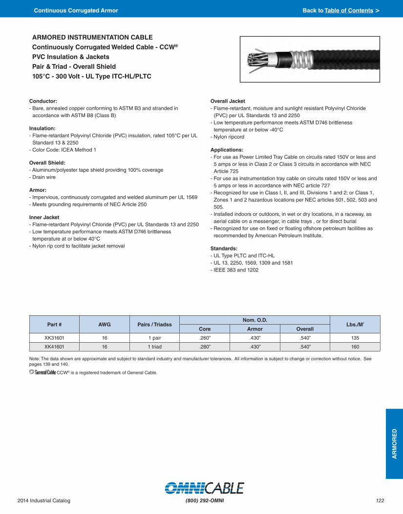
122
AR
MO
RE
D
(800) 292-OMNI2014 Industrial Catalog
Conductor:- Bare, annealed copper conforming to ASTM B3 and stranded in
accordance with ASTM B8 (Class B)
Insulation:- Flame-retardant Polyvinyl Chloride (PVC) insulation, rated 105°C per UL
Standard 13 & 2250- Color Code: ICEA Method 1
Overall Shield:- Aluminum/polyester tape shield providing 100% coverage- Drain wire
Armor:- Impervious, continuously corrugated and welded aluminum per UL 1569- Meets grounding requirements of NEC Article 250
Inner Jacket- Flame-retardant Polyvinyl Chloride (PVC) per UL Standards 13 and 2250- Low temperature performance meets ASTM D746 brittleness
temperature at or below 40°C- Nylon rip cord to facilitate jacket removal
Overall Jacket- Flame-retardant, moisture and sunlight resistant Polyvinyl Chloride
(PVC) per UL Standards 13 and 2250- Low temperature performance meets ASTM D746 brittleness
temperature at or below -40°C- Nylon ripcord
Applications:- For use as Power Limited Tray Cable on circuits rated 150V or less and
5 amps or less in Class 2 or Class 3 circuits in accordance with NEC Article 725
- For use as instrumentation tray cable on circuits rated 150V or less and 5 amps or less in accordance with NEC article 727
- Recognized for use in Class I, II, and III, Divisions 1 and 2; or Class 1, Zones 1 and 2 hazardous locations per NEC articles 501, 502, 503 and 505.
- Installed indoors or outdoors, in wet or dry locations, in a raceway, as aerial cable on a messenger, in cable trays , or for direct burial
- Recognized for use on fixed or floating offshore petroleum facilities as recommended by American Petroleum Institute.
Standards:- UL Type PLTC and ITC-HL- UL 13, 2250, 1569, 1309 and 1581- IEEE 383 and 1202
ARMORED INSTRUMENTATION CABLE
Continuously Corrugated Welded Cable - CCW®
PVC Insulation & Jackets
Pair & Triad - Overall Shield
105°C - 300 Volt - UL Type ITC-HL/PLTC
Part # AWG Pairs / TriadssNom. O.D.
Lbs./M’Core Armor Overall
XK31601 16 1 pair .260” .430” .540” 135
XK41601 16 1 triad .280” .430” .540” 160
Note: The data shown are approximate and subject to standard industry and manufacturer tolerances. All information is subject to change or correction without notice. See pages 139 and 140.
CCW® is a registered trademark of General Cable.
Continuous Corrugated Armor Back to Table of Contents >

123
AR
MO
RE
D
(800) 292-OMNI 2014 Industrial Catalog
Conductor:- Bare, annealed copper conforming to ASTM B3 and stranded in
accordance with ASTM B8 (Class B)
Insulation:- Flame-retardant Polyvinyl Chloride (PVC) insulation and nylon covering,
rated 90°C per UL Standard 83- Color Code: ICEA Method 1
Individual Shield:- Isolated and individually twisted pairs or triads with an aluminum/
polyester tape shield providing 100% coverage- Drain wire
Overall Shield:- Aluminum/polyester tape shield providing 100% coverage- Drain wire
Armor:- Impervious, continuously corrugated and welded aluminum per UL 1569
& 2225- Meets grounding requirements of NEC Article 250
Inner Jacket- Flame retardant Polyvinyl Chloride (PVC) per UL 1569, Black- Low temp performance meets ASTM D746 brttleness temp at or below
-40°C- Nylon ripcord
Overall Jacket- Flame-retardant, moisture and sunlight resistant Polyvinyl Chloride (PVC)
per UL Standards 1569, black- Low temperature performance meets ASTM D746 brittleness temperature
at or below -40°C
Applications:- For use in Class 1 remote-control and signal circuits in accordance with
NEC Article 725- Recognized for use in Class I, II, and III, Divisions 1 and 2; or Class I,
Zones 1 and 2 hazardous locations per NEC articles 501, 502, 503 and 505.
- Installed indoors or outdoors, in wet or dry locations, in a raceway, as aerial cable on a messenger, in cable trays , or for direct burial
- Recognized for use on fixed or floating offshore petroleum facilities as recommended by American Petroleum Institute
Standards:- UL Type MC-HL- UL 83, 1569, 2225, 1309 and 1581- IEEE 383 and 1202
ARMORED INSTRUMENTATION CABLE
Continuously Corrugated Welded Cable - CCW®
PVC/Nylon Insulation - PVC Jackets
Pairs & Triads - Individual & Overall Shields
90°C - 600 Volt - UL Type ITC-HL/PLTC
Note: The data shown are approximate and subject to standard industry and manufacturer tolerances. All information is subject to change or correction without notice. See pages 139 and 140.
Part # AWG Pairs / Triads Nom. O.D.
Lbs./M’Core Armor Overall
XL41602 16 2 pairs .450” .670” .780” 239
XL41604 16 4 pairs .560” .800” .910” 342
XL41608 16 8 pairs .700” .930” 1.04” 502
XL41612 16 12 pairs .850” 1.11” 1.22” 687
XL41624 16 24 pairs 1.12” 1.42” 1.53” 1140
XL41636 16 36 pairs 1.37” 1.69” 1.82” 1618
XL41650 16 50 pairs 1.57” 1.92” 1.82” 2166
XL51604 16 4 triads .610” .840” 2.05” 403
XL51608 16 8 triads .820” 1.06” 1.17” 650
XL51612 16 12 triads .980” 1.24” 1.35” 853
XL41802 18 2 pairs .410” .590” .700” 225
XL41804 18 4 pairs .480” .650” .750” 300
XL41808 18 8 pairs .600” .820” .920” 450
XL41812 18 12 pairs .780” 1.00” 1.10” 580
XL41824 18 24 pairs 1.08” 1.39” 1.49” 1050
CCW® is a registered trademark of General Cable.
Continuous Corrugated Armor Back to Table of Contents >

124
AR
MO
RE
D
(800) 292-OMNI2014 Industrial Catalog
Conductor:- Bare, annealed copper conforming to ASTM B3 and stranded in
accordance with ASTM B8 (Class B)
Insulation:- Flame-retardant Polyvinyl Chloride (PVC) insulation and nylon covering,
rated 90°C per UL Standard 83- Color Code: ICEA Method 1
Overall Shield:- Aluminum/polyester tape shield providing 100% coverage- Stranded tinned copper drain wire, same size as insulated conductors
Armor:- Impervious, continuously corrugated and welded aluminum per UL
1569 & 2225- Meets grounding requirements of NEC Article 250
Inner Jacket- Flame retardant Polyvinyl Chloride (PVC) per UL 1569, Black- Low temp performance meets ASTM D746 brittleness temp at or
below -40°C- Nylon ripcord
Overall Jacket- Flame-retardant, moisture and sunlight resistant Polyvinyl Chloride (PVC)
per UL Standards 1569, black- Low temperature performance meets ASTM D746 brittleness temperature
at or below -40°C
Applications:- For use in Class 1 remote-control and signal circuits in accordance with
NEC Article 725- Recognized for use in Class I, II, and III, Divisions 1 and 2; or Class I,
Zones 1 and 2 hazardous locations per NEC articles 501, 502, 503 and 505.
- Installed indoors or outdoors, in wet or dry locations, in a raceway, as aerial cable on a messenger, in cable trays , or for direct burial
- Recognized for use on fixed or floating offshore petroleum facilities as recommended by American Petroleum Institute
Standards:- UL Type MC-HL- UL 83, 1569, 2225, 1309 and 1581- IEEE 383 and 1202
ARMORED INSTRUMENTATION CABLE
Continuously Corrugated Welded Cable - CCW®
PVC/Nylon Insulation - PVC Jackets
Pairs & Triads - Overall Shield
90°C - 600 Volt - UL Type ITC-HL/PLTC
Note: The data shown are approximate and subject to standard industry and manufacturer tolerances. All information is subject to change or correction without notice. See pages 139 and 140.
Part # AWG Pairs / Triads Nom. O.D.
Lbs./M’Core Armor Overall
XL21601 16 1 pair .350” .530” .640” 185
XL21602 16 2 pairs .380” .580” .690” 246
XL21604 16 4 pairs .470” .710” .820” 333
XL21608 16 8 pairs .660” .890” 1.00” 466
XL21612 16 12 pairs .800” 1.06” 1.17” 604
XL21624 16 24 pairs 1.08” 1.37” 1.48” 1040
XL21636 16 36 pairs 1.32” 1.64” 1.78” 1445
XL21650 16 50 pairs 1.48” 1.83” 1.96” 1897
XL51601 16 1 triad .350” .530” .640” 195
XL21802 18 2 pairs .410” .590” .700” 222
XL21804 18 4 pairs .480” .650” .750” 268
XL21808 18 8 pairs .600” .820” .920” 420
XL21812 18 12 pairs .780” 1.00” 1.10” 560
XL21824 18 24 pairs 1.08” 1.39” 1.49” 969
CCW® is a registered trademark of General Cable.
Continuous Corrugated Armor Back to Table of Contents >

125
AR
MO
RE
D
(800) 292-OMNI 2014 Industrial Catalog
Part # AWG Conductors Nom. O.D.
Lbs./M’Armor Overall
XA51403 14 3 .490” .600” 155 XA51404 14 4 .530” .640” 183 XA51405 14 5 .580” .690” 213 XA51407 14 7 .620” .730” 257 XA51409 14 9 .710” .820” 312 XA51412 14 12 .800” .910” 386 XA51419 14 19 .930” 1.04” 544 XA51437 14 37 1.24” 1.35” 959XA51203 12 3 .530” .640” 192 XA51204 12 4 .580” .690” 229 XA51205 12 5 .620” .730” 266 XA51207 12 7 .670” .780” 328 XA51209 12 9 .800” .910” 410 XA51212 12 12 .890” .990” 510 XA51219 12 19 1.02” 1.13” 731 XA51237 12 37 1.37” 1.48” 1318 XA51003 10 3 .580” .690” 241 XA51004 10 4 .670” .780” 301 XA51005 10 5 .710” .820” 353 XA51007 10 7 .750” .860” 442 XA51009 10 9 .890” 1.00” 551
Conductor: - Bare annealed copper per ASTM B-3 - Class B stranding per ASTM B8
Insulation: - Cross-linked Polyethylene (XLPE) type XHHW-
2 per UL 44
Armor: - Impervious, continuously welded and
corrugated aluminum alloy sheath per UL 1569 - Meets grounding requirements of NEC Article
250
Jacket - Flame-retardant, moisture and sunlight-
resistant Polyvinyl Chloride (PVC), black
Applications: - Designed for use on power or control circuits - Can be installed in cable tray, wire ways, racks,
or buried directly - Suitable for exposure to hazardous locations,
Type MC-HL for Classes I, II, and III Division 1 and 2
Features: - Continuously corrugated armor provides an
impervious barrier to moisture, gas and liquids - Continuously corrugated armor provides EMI
shielding performance - Meets cold impact at -40°C - Factory assembled and tested cable for use as
an alternate to cable in conduit wiring systems - 90°C continuous operating temperature, wet
or dry - 130°C emergency rating - 250°C short circuit rating
Applications: - For use as services, feeders and branch
circuits for power, lighting, control, and signal circuits in accordance with NEC articles 330 and 725
- Class I and II, Division 2; Class III, Divisions 1 and 2, Zone 2 hazardous locations per NEC articles 501, 502, 503, and 505.
- Installed indoors or outdoors, wet or dry locations, directly buried, embedded in concrete, in a raceway, as aerial on a messenger, or as exposed runs secured to supports in accordance with NEC article 330
Standards: - IEEE 383, 1202 - UL 44, 1569, 1309, 1581 - UL Type MC, XHHW-2, SUN RES, DIR BUR - UL Listed Marine Shipboard
ARMORED CABLE
Continuously Corrugated Welded Cable - CCW®
XLPE Insulation - PVC Jacket
90°C - 600 Volt UL - Type MC
No Ground - Non-HL
Note: The data shown are approximate and subject to standard industry and manufacturer tolerances. All information is subject to change or correction without notice. See pages 139 and 140.
Colors repeat after 36 conductors.
Color Code Chart:
Cond. Num. Color Cond. Num. Color1 Black 2 Red3 Blue 4 Orange5 Yellow 6 Brown7 Red w/ Black Stripe 8 Blue w/ Black Stripe9 Orange w/ Black Stripe 10 Yellow w/ Black Stripe11 Brown w/ Black Stripe 12 Black w/ Red Stripe13 Blue w/ Red Stripe 14 Orange w/ Red Stripe15 Yellow w/ Red Stripe 16 Brown w/ Red Stripe17 Black w/ Blue Stripe 18 Red w/ Blue Stripe19 Orange w/ Blue Stripe 20 Yellow w/ Blue Stripe21 Brown w/ Blue Stripe 22 Black w/ Orange Stripe23 Red w/ Orange Stripe 24 Blue w/ Orange Stripe25 Yellow w/ Orange Stripe 26 Brown w/ Orange Stripe27 Black w/ Yellow Stripe 28 Red w/ Yellow Stripe29 Blue w/ Yellow Stripe 30 Orange w/ Yellow Stripe31 Brown w/ Yellow Stripe 32 Black w/ Brown Stripe33 Red w/ Brown Stripe 34 Blue w/ Brown Stripe35 Orange w/ Brown Stripe 36 Yellow w/ Brown Stripe
CCW® is a registered trademark of General Cable.
Continuous Corrugated Armor Back to Table of Contents >

126
AR
MO
RE
D
(800) 292-OMNI2014 Industrial Catalog
Colors repeat after 36 conductors.
Conductor:- Bare annealed copper per ASTM B-3 - Compressed Class B stranding per ASTM B8
Insulation:- Cross-linked Polyethylene (XLPE) type
XHHW-2 per UL 44
Grounding Conductor:- Class B stranded bare copper per ASTM B3
and B8- Cross-linked Polyethylene (XLPE) insulation,
green- Sized in accordance with NEC Table 250.122
Armor:- Impervious, continuously welded and
corrugated aluminum alloy sheath per UL 1569 and UL 2225
- Meets grounding requirements of NEC Article 250
Jacket- Black Polyvinyl Chloride (PVC), sunlight and
oil resistant, per UL 1569, 90°C temperature rating
Applications:- Designed for use on power or control circuits- Can be installed in cable tray, wire ways,
racks, or buried directly- Suitable for exposure to hazardous locations,
Type MC-HL for Classes I, II, and III Division 1 and 2
Standards:- UL 44, XHHW-2- UL 1309 Marine Shipboard- UL 1569 Type MC and UL 2225 Type MC-HL- UL 1581- IEEE 383- IEEE 1202
ARMORED CABLE
Continuously Corrugated Welded Cable - CCW®
XLPE Insulation - PVC Jacket
90°C - 600 Volt - UL Type MC-HL
Note: The data shown are approximate and subject to standard industry and manufacturer tolerances. All information is subject to change or correction without notice. See pages 139 and 140.
Part # AWG Conductors Ground AWG Nom. O.D.
Lbs./M’Armor Overall
X11403 14 3 14 .530” .640” 192 X11404 14 4 14 .580” .690” 222 X11405 14 5 14 .600” .710” 245 X11406 14 6 14 .620” .730” 267 X11408 14 8 14 .710” .820” 321 X11409 14 9 14 .740” .850” 377 X11411 14 11 14 .800” .910” 395 X11418 14 18 14 .930” 1.04” 554 X11436 14 36 14 1.24” 1.35” 948 X11437 14 37 14 1.22” 1.32” 1030 X11202 12 2 12 .530” .640” 200 X11203 12 3 12 .580” .690” 239 X11204 12 4 12 .670” .780” 310 X11205 12 5 12 .670” .780” 324 X11206 12 6 12 .670” .780” 338 X11207 12 7 12 .710” .820” 408 X11208 12 8 12 .800” .910” 426 X11211 12 11 12 .890” 1.00” 519 X11212 12 12 12 .885” .995” 584 X11218 12 18 12 1.02” 1.13” 739 X11236 12 36 12 1.37” 1.48” 1302 X11002 10 2 10 .580” .690” 253 X11003 10 3 10 .620” .730” 303 X11004 10 4 10 .670” .780” 348 X11006 10 6 10 .750” .860” 451 X11008 10 8 10 .890” 1.00” 568 X11011 10 11 10 .970” 1.08” 704
Color Code Chart:
Cond. Num. Color Cond. Num. Color1 Black 2 Red3 Blue 4 Orange5 Yellow 6 Brown7 Red w/ Black Stripe 8 Blue w/ Black Stripe9 Orange w/ Black Stripe 10 Yellow w/ Black Stripe11 Brown w/ Black Stripe 12 Black w/ Red Stripe13 Blue w/ Red Stripe 14 Orange w/ Red Stripe15 Yellow w/ Red Stripe 16 Brown w/ Red Stripe17 Black w/ Blue Stripe 18 Red w/ Blue Stripe19 Orange w/ Blue Stripe 20 Yellow w/ Blue Stripe21 Brown w/ Blue Stripe 22 Black w/ Orange Stripe23 Red w/ Orange Stripe 24 Blue w/ Orange Stripe25 Yellow w/ Orange Stripe 26 Brown w/ Orange Stripe27 Black w/ Yellow Stripe 28 Red w/ Yellow Stripe29 Blue w/ Yellow Stripe 30 Orange w/ Yellow Stripe31 Brown w/ Yellow Stripe 32 Black w/ Brown Stripe33 Red w/ Brown Stripe 34 Blue w/ Brown Stripe35 Orange w/ Brown Stripe 36 Yellow w/ Brown Stripe
CCW® is a registered trademark of General Cable.
Continuous Corrugated Armor Back to Table of Contents >

127
AR
MO
RE
D
(800) 292-OMNI 2014 Industrial Catalog
Color Code Chart (4 AWG and larger):
Color Code Chart (6 AWG and smaller):
Cond. Num. Cond. Marking Cond. Num. Cond. Marking
1 “1” One 2 “2” Two
3 “3” Three 4 “4” Four
Cond. Num. Color Cond. Num. Color
1 Black 2 Red
3 Blue 4 Orange
Conductor:- Bare annealed copper per ASTM B-3 - 10 AWG and smaller are compressed
Class B stranding per ASTM B8- 8 AWG and larger are compact stranding
per ASTM B496
Insulation:- Cross-linked Polyethylene (XLPE) type
XHHW-2 per UL 44
Grounding Conductors:- Class B stranded bare copper per ASTM
B3 & B8- Sized in accordance with NEC Table
250.122
Armor:- Impervious, continuously welded and
corrugated aluminum alloy sheath
Jacket- Black Polyvinyl Chloride (PVC), sunlight
and oil resistant, per UL 1569, 90°C temperature rating
Applications:- Designed for use on power or control
circuits- Can be installed in cable tray, wire ways,
racks, or buried directly- This cable has three symmetrically placed
grounds to reduce problems associated with pulse - width modulated AC drives. Suitable for VFD applications.
- Suitable for exposure to hazardous locations, Type MC-HL for Classes I, II, and III Division 1 and 2
Standards:- UL 44, XHHW-2- UL 1309 Marine Shipboard- UL 1569 Type MC and UL 2225 Type
MC-HL- UL 1581- Designated Type MC as per NEC Article
334- IEEE 383- IEEE 1202
ARMORED CABLE
Continuously Corrugated Welded Cable - CCW®
XLPE Insulation - PVC Jacket
90°C - 600 Volt - UL Type MC-HL
3-Conductor VFD & 4-Conductor
Part # AWG Conductors Ground
AWG Nom. O.D.
Lbs./M’Armor Overall
X21403 14 3 3 × 18 .530” .640” 163
X21404 14 4 3 × 18 .580” .690” 226
X21203 12 3 3 × 16 .580” .690” 243
X21204 12 4 3 × 16 .670” .780” 291
X21003 10 3 3 × 14 .620” .730” 305
X21004 10 4 3 × 14 .670” .780” 354
X20803 8 3 3 × 14 .710” .810” 392
X20603 6 3 3 × 12 .800” .900” 534
X20403 4 3 3 × 12 .890” .990” 716
X20203 2 3 3 × 10 1.02” 1.27” 1013
X20103 1 3 3 × 10 1.15” 1.26” 1119
X21/003 1/0 3 3 × 10 1.24” 1.34” 1496
X22/003 2/0 3 3 × 10 1.34” 1.44” 1801
X23/003 3/0 3 3 × 8 1.47” 1.58” 2262
X24/003 4/0 3 3 × 8 1.60” 1.73” 2722
X225003 250 3 3 × 8 1.74” 1.87” 3195
X235003 350 3 3 × 7 1.96” 2.09” 4284
X250003 500 3 3 × 6 2.28” 2.44” 6035
X275003 750 3 3 × 5 2.75” 2.92” 8854
Note: The data shown are approximate and subject to standard industry and manufacturer tolerances. All information is subject to change or correction without notice. See pages 139 and 140.
CCW® is a registered trademark of General Cable.
Continuous Corrugated Armor Back to Table of Contents >

128
AR
MO
RE
D
(800) 292-OMNI2014 Industrial Catalog
Conductor:- Bare, annealed copper conforming to ASTM B-3- 10AWG and smaller are Class B compressed stranding per ASTM B8- 8AWG and larger are compact stranding per ASTM B496
Insulation:- Cross-linked Polyethylene (XLPE) type XHHW per UL 44, listed XHHW-2
Grounding Conductor:- Class B stranded bare annealed copper per ASTM B3 and B8
Continuously Corrugated Armor:- Impervious, continuously welded and corrugated aluminum alloy sheath
Jacket- Flame retardant, moisture and sunlight resistant Polyvinyl Chloride
(PVC), black
Applications:- For use as services, feeders and branch circuits for power, lighting,
control, and signal circuits in accordance with NEC articles 330 and 725- Class I, II and III, Divisions 1 and 2; Class I, Zones 1 and 2 hazardous
locations per NEC articles 501, 502, 503, and 505.- Installed indoors or outdoors, wet or dry locations, directly buried,
embedded in concrete, in a raceway, as aerial on a messenger, or as exposed runs secured to supports in accordance with NEC article 330
- Recognized for use on fixed or floating offshore petroleum facilities as recommended by the American Petroleum Institute
Features:- Continuously corrugated armor provides an impervious barrier to
moisture, gas and liquids- Continuously corrugated armor provides EMI shielding performance- Meets cold impact at -40°C- Factory assembled and tested cable for use as an alternate to cable in
conduit wiring systems- 90°C continuous operating temperature, wet or dry- 130°C emergency rating- 250°C short circuit rating
Standards:- UL Type MC-HL, XHHW-2- UL Listed Marine Shipboard- UL 44, 1309, 1569, 1581 and 2225- IEEE 383 and 1202
ARMORED CABLE
Continuously Corrugated Welded Cable - CCW®
Composite Power & Control
XLPE Insulation - PVC Jacket
90°C - 600 Volt - UL Type MC-HL
Note: The data shown are approximate and subject to standard industry and manufacturer tolerances. All information is subject to change or correction without notice. See pages 139 and 140.
Part # Power Conductor
Size Control
Conductor Size Bare Ground
AWG
Nom. O.D.Lbs./M’
Armor Overall
XAC31003 3 × 10AWG 4 x #12AWG 10 .750” .860” 430
XAC30803 3 × 8AWG 4 x #12AWG 10 .890” .990” 535
XAC30603 3 × 6AWG 4 x #12AWG 8 .930” 1.03” 660
XAC30403 3 × 4AWG 4 x #12AWG 8 .970” 1.08” 815
Color Code for Conductors, 6AWG and smaller:
Color Code for Conductors, 4AWG and larger:
Cond. Num. Color Cond. Num. Color
1 Black 2 Red
3 Blue 4 Yellow
- Black with printed numbers per ICEA Method 4
CCW® is a registered trademark of General Cable.
Continuous Corrugated Armor Back to Table of Contents >

129
AR
MO
RE
D
(800) 292-OMNI 2014 Industrial Catalog
Color Code for 4AWG and larger:
Color Code for 6AWG and smaller:
- Black with printed numbers per ICEA Method 4
Cond. Num. Color Cond. Num. Color
1 Black 2 Red
3 Blue 4 Orange
Conductor:- Bare, annealed copper per ASTM B3 - Compact stranding per ASTM B496
Insulation:- Cross-linked Polyethylene (XLPE) type
XHHW per UL 44, listed XHHW-2
Ground:- Class B stranded bare annealed copper
per ASTM B3 and B8
Armor:- Impervious, continuously welded and
corrugated aluminum alloy sheath per UL 1569 and UL 2225
Jacket:- Flame retardant, moisture and sunlight
resistant Polyvinyl Chloride PVC)
Applications:- For use as services, feeders and branch
circuits for power, lighting, control, and signal circuits in accordance with NEC articles 330 and 725
- Class I, II and III, Divisions 1 and 2; Class I, Zones 1 and 2 hazardous locations per NEC articles 501, 502, 503, and 505.
- Installed indoors or outdoors, wet or dry locations, directly buried, embedded in concrete, in a raceway, as aerial on a messenger, or as exposed runs secured to supports in accordance with NEC article 330
Features:- Continuously corrugated armor provides
an impervious barrier to moisture, gas and liquids
- Continuously corrugated armor provides EMI shielding performance
- Meets cold impact at -40°C- Factory assembled and tested cable for
use as an alternate to cable in conduit wiring systems
- 90°C continuous operating temperature, wet or dry
- 130°C emergency rating- 250°C short circuit rating
Standards:- UL 44, 1569, 2225, 1309, 1581- IEEE 383, 1202
ARMORED CABLE
Continuously Corrugated Welded Cable - CCW®
Variable Frequency Drive Cable
XLPE Insulation - PVC Jacket
90°C - 600 Volt - UL Type MC-HL 4-Conductor
Part # AWG Conductors Ground
AWG Nom. O.D.
Lbs./M’Armor Overall
XA60804 8 4 10 .800” .900” 473
XA60604 6 4 8 .890” .990” 641
XA60404 4 4 8 .970” 1.08” 860
XA60204 2 4 6 1.15” .1.26” 1267
XA62/004 2/0 4 6 1.51” .1.64” 2351
XA64/004 4/0 4 4 1.78” .1.91” 3491
XA635004 350 4 3 2.19” .2.35” 5536
XA650004 500 4 2 2.49” .2.65” 7704
Note: The data shown are approximate and subject to standard industry and manufacturer tolerances. All information is subject to change or correction without notice. See pages 139 and 140.
CCW® is a registered trademark of General Cable.
Continuous Corrugated Armor Back to Table of Contents >

130
AR
MO
RE
D
(800) 292-OMNI2014 Industrial Catalog
Conductor:- Bare annealed copper per ASTM B3- Compact stranding per ASTM B496
Extruded Strand Shield:- Extruded thermoset semi-conductor stress control layer over conductor
per ICEA S-93-639 and UL 1072
Insulation:- Ethylene Propylene Rubber (EPR)
Extruded Insulation Shield:- Thermoset semi-conducting polymeric layer, free stripping from the
insulation per ICEA S-93-639 and UL 1072
Shield:- 5 mil annealed bare copper tape with 25% overlap- Color coded polymeric identification tape laid under the shield: black,
red, & blue
Grounding Conductor:- Three split Class B stranded bare annealed copper grounding
conductors- Sized in accordance with UL 1072 and NEC Article 250
Armor:- Impervious, continuously welded and corrugated aluminum alloy sheath
Jacket- Flame-retardant, moisture and sunlight resistant Polyvinyl Chloride
(PVC), yellow- Low temperature performance meets ASTM D746 brittleness
temperature at or below 40°C
Applications:- Variable Frequency Drives: 3-conductor CCW armored cables with 3
symmetrical grounding wire are the preferred wiring method for use with AC motors controlled by pulse-width modulated inverters in VFD applications
- For use in feeders and branch circuits in industrial power distribution systems per NEC articles 328 and 330
- Approved for Classes I, II and III, Divisions 1 and 2; and Class I, Zones 1 and 2, hazardous locations covered under NEC Articles 501, 502, 503 and 505.
- Installed on metal racks, troughs, in raceways, in cable trays or secured to supports spaced no more than 6 feet apart
- Installed in both exposed and concealed work, wet or dry locations, directly buried or embedded in concrete
Features:- Cable meets cold impact at -40°C- 105°C continuous operating temperature, wet or dry- 140°C emergency rating- 250°C short circuit rating
Standards:- UL 1072- UL 1569- UL 2225- UL 1309- IEEE 383- IEEE 1202
ARMORED CABLE
Continuously Corrugated Welded Cable - CCW®
Variable Frequency Drive Cable
EPR Insulation - PVC Jacket
105°C - UL Type MC-HL or MV-105
5kV(133%)/8kV(100%) - 3-Conductor - Shielded
Part # AWG Conductors Ground AWG Insulation Thickness
Nom. O.D. Lbs./M’
Armor Overall
XMVE20403 4 3 3 × 10AWG .115” 1.51” 1.65” 1418
XMVE20203 2 3 3 × 10AWG .115” 1.64” 1.78” 1731
XMVE21/003 1/0 3 3 × 8AWG .115” 1.78” 1.91” 2259
XMVE22/003 2/0 3 3 × 8AWG .115” 1.92” 2.05” 2626
XMVE24/003 4/0 3 3 × 7AWG .115” 2.15” 2.28” 3650
XMVE225003 250 3 3 × 7AWG .115” 2.23” 2.36” 4060
XMVE235003 350 3 3 × 6AWG .115” 2.45” 2.61” 5045
XMVE250003 500 3 3 × 5AWG .115” 2.75” 2.92” 7137
XMVE275003 750 3 3 × 4AWG .115” 3.32” 3.50” 10268
Note: The data shown are approximate and subject to standard industry and manufacturer tolerances. All information is subject to change or correction without notice. See pages 139 and 140.
CCW® is a registered trademark of General Cable.
Continuous Corrugated Armor Back to Table of Contents >
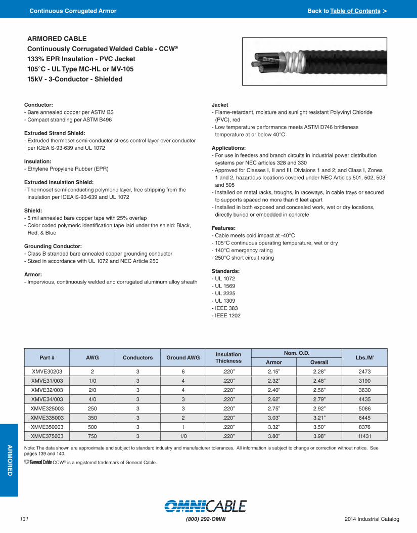
131
AR
MO
RE
D
(800) 292-OMNI 2014 Industrial Catalog
Conductor:- Bare annealed copper per ASTM B3- Compact stranding per ASTM B496
Extruded Strand Shield:- Extruded thermoset semi-conductor stress control layer over conductor
per ICEA S-93-639 and UL 1072
Insulation:- Ethylene Propylene Rubber (EPR)
Extruded Insulation Shield:- Thermoset semi-conducting polymeric layer, free stripping from the
insulation per ICEA S-93-639 and UL 1072
Shield:- 5 mil annealed bare copper tape with 25% overlap- Color coded polymeric identification tape laid under the shield: Black,
Red, & Blue
Grounding Conductor:- Class B stranded bare annealed copper grounding conductor- Sized in accordance with UL 1072 and NEC Article 250
Armor:- Impervious, continuously welded and corrugated aluminum alloy sheath
Jacket- Flame-retardant, moisture and sunlight resistant Polyvinyl Chloride
(PVC), red- Low temperature performance meets ASTM D746 brittleness
temperature at or below 40°C
Applications:- For use in feeders and branch circuits in industrial power distribution
systems per NEC articles 328 and 330- Approved for Classes I, II and III, Divisions 1 and 2; and Class I, Zones
1 and 2, hazardous locations covered under NEC Articles 501, 502, 503 and 505
- Installed on metal racks, troughs, in raceways, in cable trays or secured to supports spaced no more than 6 feet apart
- Installed in both exposed and concealed work, wet or dry locations, directly buried or embedded in concrete
Features:- Cable meets cold impact at -40°C- 105°C continuous operating temperature, wet or dry- 140°C emergency rating- 250°C short circuit rating
Standards:- UL 1072- UL 1569- UL 2225- UL 1309- IEEE 383- IEEE 1202
ARMORED CABLE
Continuously Corrugated Welded Cable - CCW®
133% EPR Insulation - PVC Jacket
105°C - UL Type MC-HL or MV-105
15kV - 3-Conductor - Shielded
Part # AWG Conductors Ground AWG Insulation Thickness
Nom. O.D. Lbs./M’
Armor Overall
XMVE30203 2 3 6 .220” 2.15” 2.28” 2473
XMVE31/003 1/0 3 4 .220” 2.32” 2.48” 3190
XMVE32/003 2/0 3 4 .220” 2.40” 2.56” 3630
XMVE34/003 4/0 3 3 .220” 2.62” 2.79” 4435
XMVE325003 250 3 3 .220” 2.75” 2.92” 5086
XMVE335003 350 3 2 .220” 3.03” 3.21” 6445
XMVE350003 500 3 1 .220” 3.32” 3.50” 8376
XMVE375003 750 3 1/0 .220” 3.80” 3.98” 11431
Note: The data shown are approximate and subject to standard industry and manufacturer tolerances. All information is subject to change or correction without notice. See pages 139 and 140.
CCW® is a registered trademark of General Cable.
Continuous Corrugated Armor Back to Table of Contents >
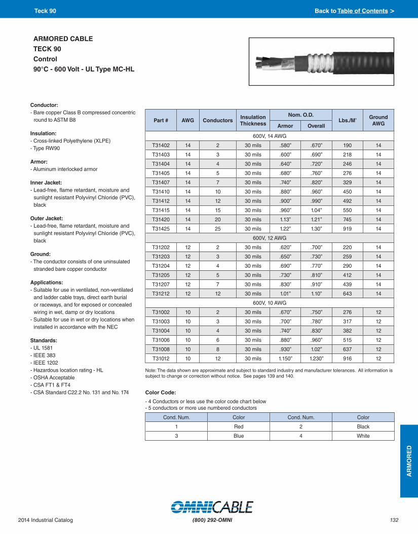
132
AR
MO
RE
D
(800) 292-OMNI2014 Industrial Catalog
Color Code:
- 4 Conductors or less use the color code chart below- 5 conductors or more use numbered conductors
Cond. Num. Color Cond. Num. Color
1 Red 2 Black
3 Blue 4 White
Conductor:- Bare copper Class B compressed concentric
round to ASTM B8
Insulation:- Cross-linked Polyethylene (XLPE)- Type RW90
Armor:- Aluminum interlocked armor
Inner Jacket:- Lead-free, flame retardant, moisture and
sunlight resistant Polyvinyl Chloride (PVC), black
Outer Jacket:- Lead-free, flame retardant, moisture and
sunlight resistant Polyvinyl Chloride (PVC), black
Ground:- The conductor consists of one uninsulated
stranded bare copper conductor
Applications:- Suitable for use in ventilated, non-ventilated
and ladder cable trays, direct earth burial or raceways, and for exposed or concealed wiring in wet, damp or dry locations
- Suitable for use in wet or dry locations when installed in accordance with the NEC
Standards:- UL 1581- IEEE 383 - IEEE 1202- Hazardous location rating - HL- OSHA Acceptable - CSA FT1 & FT4- CSA Standard C22.2 No. 131 and No. 174
ARMORED CABLE
TECK 90
Control
90°C - 600 Volt - UL Type MC-HL
Part # AWG Conductors Insulation Thickness
Nom. O.D. Lbs./M’
Ground AWGArmor Overall
600V, 14 AWG
T31402 14 2 30 mils .580” .670” 190 14
T31403 14 3 30 mils .600” .690” 218 14
T31404 14 4 30 mils .640” .720” 246 14
T31405 14 5 30 mils .680” .760” 276 14
T31407 14 7 30 mils .740” .820” 329 14
T31410 14 10 30 mils .880” .960” 450 14
T31412 14 12 30 mils .900” .990” 492 14
T31415 14 15 30 mils .960” 1.04” 550 14
T31420 14 20 30 mils 1.13” 1.21” 745 14
T31425 14 25 30 mils 1.22” 1.30” 919 14
600V, 12 AWG
T31202 12 2 30 mils .620” .700” 220 14
T31203 12 3 30 mils .650” .730” 259 14
T31204 12 4 30 mils .690” .770” 290 14
T31205 12 5 30 mils .730” .810” 412 14
T31207 12 7 30 mils .830” .910” 439 14
T31212 12 12 30 mils 1.01” 1.10” 643 14
600V, 10 AWG
T31002 10 2 30 mils .670” .750” 276 12
T31003 10 3 30 mils .700” .780” 317 12
T31004 10 4 30 mils .740” .830” 382 12
T31006 10 6 30 mils .880” .960” 515 12
T31008 10 8 30 mils .930” 1.02” 637 12
T31012 10 12 30 mils 1.150” 1.230” 916 12
Note: The data shown are approximate and subject to standard industry and manufacturer tolerances. All information is subject to change or correction without notice. See pages 139 and 140.
Teck 90 Back to Table of Contents >

133
AR
MO
RE
D
(800) 292-OMNI 2014 Industrial Catalog
Conductor:- Bare copper Class B- In sizes 6 AWG to 500, the conductors
may be compact stranded to reduce cable diameter and weight
Insulation:- Cross-linked Polyethylene (XLPE) - Type RW90
Ground:- The conductor consists of one
uninsulated stranded bare copper conductor
Armor:- Aluminum interlocked armor
Inner Jacket- Lead-free, flame retardant, moisture
and sunlight resistant Polyvinyl Chloride (PVC), black
Outer Jacket- Lead-free, flame retardant, moisture
and sunlight resistant Polyvinyl Chloride (PVC), black
Applications:- Suitable for use in ventilated, non-
ventilated and ladder cable trays, direct earth burial or raceways, and for exposed or concealed wiring in wet, damp or dry locations
- Suitable for use in wet or dry locations when installed in accordance with the NEC
- Suitable for use in all hazardous locations when used with certified HL cable glands
Standards:- UL 1581- IEEE 383 and 1202- OSHA Acceptable - Hazardous location rating - HL- CSA FT1 & FT4- CSA Standard C22.2 No. 131 and
No. 174
ARMORED CABLE
TECK 90
Control & Power
90°C - 1000 Volt - UL Type MC-HL
Note: The data shown are approximate and subject to standard industry and manufacturer tolerances. All information is subject to change or correction without notice. See pages 139 and 140.
Part # AWG Conductors Insulation Thickness
Nom. O.D. Lbs./M’
Ground AWGArmor Overall
1kV
T30803 8 3 45 mils .860” .940” 482 10
T30804 8 4 45 mils .920” 1.00” 570 10
T30603 6 3 60 mils 1.03” 1.13” 695 8
T30604 6 4 60 mils 1.04” 1.25” 883 8
T30403 4 3 60 mils 1.16” 1.25” 950 8
T30404 4 4 60 mils 1.18” 1.27” 1161 8
T30203 2 3 60 mils 1.28” 1.37” 1300 6
T30204 2 4 60 mils 1.45” 1.53” 1568 6
T31/003 1/0 3 80 mils 1.56” 1.68” 1871 6
T32/003 2/0 3 80 mils 1.65” 1.77” 2177 6
T33/003 3/0 3 80 mils 1.75” 1.87” 2619 4
T34/003 4/0 3 80 mils 1.86” 1.98” 3176 4
T335003 350 3 90 mils 2.26” 2.40” 4989 3
T350003 500 3 90 mils 2.52” 2.66” 6706 3
Color Code:
Cond. Num. Color Cond. Num. Color
1 Black 2 Red
3 Blue 4 White
Teck 90 Back to Table of Contents >

134
TEC
HN
ICA
L
(800) 292-OMNI2014 Industrial Catalog
Copper Conductor and Stranding Data
Approx. O.D.
Lbs. per 1,000’
Circular MILS
Size AWG/MCM
Concentric StrandRope Lay
Concentric StrandRope Lay Bunch
Strand
Class AA
Class A
Class B
Class C
Class D
Class G
Class HClass K 30 AWG
Class M 34 AWG
0.0050 0.0757 25.00 36
0.0056 0.0954 31.52 35
0.0063 0.1203 39.75 34
0.0071 0.1517 50.13 33
0.0080 0.1913 63.21 32
0.0089 0.2413 79.70 30
0.0100 0.3042 100.5 30
0.0113 0.3836 126.7 29
0.0126 0.4837 159.8 28
0.0142 0.6100 201.5 27
0.0159 0.7692 254.1 26
0.0179 0.9699 320.4 25
0.0201 1.223 404.0 24
0.0226 1.542 509.5 23
0.0254 1.945 642.4 22
0.0285 2.452 810.1 21
0.0363 3.154 1,020 20 7 19 10 26
0.0456 5.015 1,620 18 7 19 16 41
0.0576 7.974 2,580 16 7 19 26 65
0.0726 12.68 4,110 14 7 19 37 49 41 104
0.0915 20.16 6,530 12 7 19 37 49 65 186
0.1160 32.06 10,380 10 7 19 37 49 104 259
0.1600 40.42 13,090 9 7 19 37 49 133
0.1460 51.00 16,510 8 7 19 37 49 133 168 420
0.1840 80.90 26,240 6 7 19 37 49 133 266 665
0.2320 129 41,740 4 3 7 7 19 37 49 133 420 1,064
0.2600 162 52,620 3 3 7 7 19 37 49 133 532 1,323
0.2990 205 66,630 2 3 7 7 19 37 49 133 665 1,666
0.3320 259 83,690 1 3 7 19 37 61 133 259 836 2,107
0.3730 326 105,600 1/0 7 7 19 37 61 133 259 1,064 2,646
0.4190 411 133,100 2/0 7 7 19 37 61 133 259 1,323 3,325
0.4700 518 167,800 3/0 7 7 19 37 61 133 259 1,666 4,256
0.5280 653 211,600 4/0 7 7 19 37 61 133 259 2,107 5,320
0.5750 772 250,000 250 12 19 37 61 91 259 427 2,499 6,384
0.6300 925 300,000 300 12 19 37 61 91 259 427 2,989 7,581
0.6810 1,080 350,000 350 12 19 37 61 91 259 427 3,458 8,806
0.7280 1,236 400,000 400 19 19 37 61 91 259 427 3,990 10,101
0.8130 1,542 500,000 500 19 37 37 61 91 259 427 5,054 12,691
0.8930 1,850 600,000 600 37 37 61 91 127 427 703 5,985 14,945
0.9980 2,316 750,000 750 37 61 61 91 127 427 703 7,581 18,788
1.152 3,086 1,000,000 1,000 37 61 61 91 127 427 703 10,101 25,193
Strand Data Back to Table of Contents >
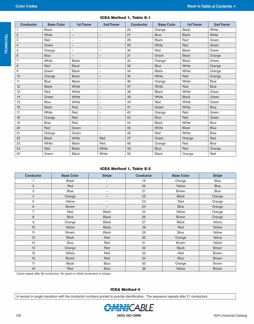
135
TEC
HN
ICA
L
(800) 292-OMNI 2014 Industrial Catalog
ICEA Method 1, Table E-1
Conductor Base Color 1st Tracer 2nd Tracer Conductor Base Color 1st Tracer 2nd Tracer
1 Black – – 26 Orange Black White
2 White – – 27 Blue Black White
3 Red – – 28 Black Red Green
4 Green – – 29 White Red Green
5 Orange – – 30 Red Black Green
6 Blue – – 31 Green Black Orange
7 White Black – 32 Orange Black Green
8 Red Black – 33 Blue White Orange
9 Green Black – 34 Black White Orange
10 Orange Black – 35 White Red Orange
11 Blue Black – 36 Orange White Blue
12 Black White – 37 White Red Blue
13 Red White – 38 Black White Green
14 Green White – 39 White Black Green
15 Blue White – 40 Red White Green
16 Black Red – 41 Green White Blue
17 White Red – 42 Orange Red Green
18 Orange Red – 43 Blue Red Green
19 Blue Red – 44 Black White Blue
20 Red Green – 45 White Black Blue
21 Orange Green – 46 Red White Blue
22 Black White Red 47 Green Orange Red
23 White Black Red 48 Orange Red Blue
24 Red Black White 49 Blue Red Orange
25 Green Black White 50 Black Orange Red
ICEA Method 1, Table E-2
Conductor Base Color Stripe Conductor Base Color Stripe
1 Black – 19 Orange Blue
2 Red – 20 Yellow Blue
3 Blue – 21 Brown Blue
4 Orange – 22 Black Orange
5 Yellow – 23 Red Orange
6 Brown – 24 Blue Orange
7 Red Black 25 Yellow Orange
8 Blue Black 26 Brown Orange
9 Orange Black 27 Black Yellow
10 Yellow Black 28 Red Yellow
11 Brown Black 29 Blue Yellow
12 Black Red 30 Orange Yellow
13 Blue Red 31 Brown Yellow
14 Orange Red 32 Black Brown
15 Yellow Red 33 Red Brown
16 Brown Red 34 Blue Brown
17 Black Blue 35 Orange Brown
18 Red Blue 36 Yellow Brown
Colors repeat after 36 conductors. No green or white conductors or stripes.
ICEA Method 4
A neutral or single insulation with the conductor numbers printed to provide identification. The sequence repeats after 21 conductors.
Color Codes Back to Table of Contents >

136
TEC
HN
ICA
L
(800) 292-OMNI2014 Industrial Catalog
Temperature Conversions
Celsius Fahrenheit Celsius Fahrenheit Conversion Formula
-40 -40 120 248
Celsius to Fahrenheit
F = (C x 1.8) + 32
Fahrenheit to Celsius
C = (F - 32) / 1.8
-30 -22 130 266
-20 -4 140 284
-10 14 150 302
0 32 160 320
10 50 170 338
40 104 200 392
50 122 210 410
60 140 220 428
80 176 240 464
90 194 250 482
100 212 450 810
110 230 538 1000
Comparitive Properties of Insulation Compounds
Insulation Silicone TFE PVC XLP PE EPR TPR
Heat Resistance 0 0 G-E G-E G E G
Oil Resistance F-G 0 G-E G G F G
Water Resistance G-E E G-E E E G-E G
Alkali Resistance F-G E G-E G-E G-E G-E E
Acid Resistance F-G E G-E G-E G-E G-E G-E
Electrical Properties 0 E F-G E-O E E G
Low Temp. Flexibility 0 0 P-G G-E F G G
Weather, Sun Resistance 0 0 G-E E E E G-E
Abrasion Resistance P G F-G G-E F G G
Alcohol Resistance G E G-E G-E E P E
Flame Resistance F-G 0 E P P P G
P - Poor F - Fair G - Good E - Excellent O - Outstanding
Comparitive Properties of Jacket Compounds
Jacket Neoprene Teflon PVC CSPE PE CPE TPR
Heat Resistance 0 0 G-E G-E G E G
Oil Resistance F-G 0 G-E G G F G
Water Resistance G-E E G-E E E G-E G
Alkali Resistance F-G E G-E G-E G-E G-E E
Acid Resistance F-G E G-E G-E G-E G-E G-E
Electrical Properties 0 E F-G E-O E E G
Low Temp. Flexibility 0 0 P-G G-E F G G
Weather, Sun Resistance 0 0 G-E E E E G-E
Abrasion Resistance P G F-G G-E F G G
Alcohol Resistance G E G-E G-E E P E
Flame Resistance F-G 0 E P P P G
P - Poor F - Fair G - Good E - Excellent O - Outstanding
Temperature Conversions/Insulation Compounds/Jacketing Compounds Back to Table of Contents >

137
IND
EX
(800) 292-OMNI 2014 Industrial Catalog
1229500 - 1229504 88
1329500 - 1329504 88
29500 - 29507 80
29500T - 29507T 83
29510 - 29513 82
29520C - 29532C 87
29528 - 29532 84
29528T - 29532T 86
29533 - 29535 85
29536 - 29542 81
29543 - 29547 85
A1… 34 - 37
A1…-BWG 38
A14… 40
A16… 41
A17… 52
A2… 49 - 50
A3… 39
A4… 51
A5… 43
A6… 44
A8… 66
AC3… 42
AF1… 45 - 46
AF16… 48
AF2… 53
AF3… 47
AF6… 22
AF7… 24
AS1… 68 - 71
AZ1… 54
AZ3… 55
B1… 58 - 59
B1…-V 63
B14… 77
B15… 77
B16… 77
B17… 77
B18… 78
B19… 78
B2… 64
B2…-V 62
B3…-V 61
B4… 72
B45… 79
B5… 74 - 76
B6… 73
B8… 65
B9… 6
BE1… 60
BJT1… 56
BJ1… 57
BJ1…-V 63
C3… 8 - 9
C4… 7
C5… 10 - 11
C6… 3
C7… 4
C8… 5
FC1… 67
I1… 29
I2… 29
I3… 29
I4… 29
I5… 33
I6… 30
I7… 31
I8… 32
IF1… 27
IF6… 28
K3… 16
KT3… 15
L1… 18
L2… 21
L3… 17
L4… 20
L5… 23
L6… 19
L7… 2
L8… 1
LZ2… 25
LZ4… 26
M6… 13
M7… 12
MU3… 107
MUP1… 108
MUP3… 113
MVE1… 98
MVE2… 101
MVE2… 103
MVE3… 104, 111
MVE4… 112
MVH1… 97
MVU1… 102
MVU2… 106
MVU4… 106
MVX1… 99 - 100
MVX3… 105
MVX3…A 109
MVX3…C 110
PV3… 14
T3… 132 - 133
T6… 114 - 115
TP1… 89 - 93
TP2… 94 - 96
X1… 126
X2… 127
XA5… 125
XA6… 129
XAC3… 128
XK3… 122
XK4… 122
XL2… 124
XL3… 121
XL4… 123
XL5… 123 - 124
XL6… 121
XMVE2… 130
XMVE3… 131
Y1… 116 - 118
Y2… 119
Y3… 120
Part Number Page Part Number Page Part Number Page
Part Number Index Back to Table of Contents >

(800) 292-OMNI2014 Industrial Catalog 138(800) 292-OMNI2014 Industrial Catalog
The information and other materials (“Information”) in this Catalog are provided as a guide to product selection only. Information about or relating to a product was provided by the product manufacturer or is based thereon. Omni Cable Corporation (“Omni Cable”) believes the information contained herein to be correct as of the date of publication; however, the Catalog could contain technical or other inaccuracies or typographical errors. Omni Cable disclaims all responsibility and liability for any errors or omissions and reserves the right to modify or withdraw any product or description at any time without notice. THE INFORMATION IN THIS CATALOG OR ON OMNI CABLE’S WEBSITES IS PROVIDED TO YOU “AS IS” AND WITHOUT ANY REPRESENTATION OR WARRANTY OF ACCURACY OR COMPLETENESS OF INFORMATION AND WITHOUT ANY OTHER WARRANTY, EXPRESS OR IMPLIED, OF ANY KIND, INCLUDING, BUT NOT LIMITED TO, ANY IMPLIED WARRANTY OF QUALITY OR CONDITION, MERCHANTABILITY, FITNESS FOR A PARTICULAR PURPOSE, SUITABILITY, OR NON-INFRINGEMENT.
Omni Cable makes no warranties, express or implied, with respect to any product included or described in this Catalog or on Omni Cable’s websites. The warranty, if any, provided by the manufacturer of the product shall be the sole and exclusive warranty available to the buyer or anyone else. The applicable manufacturer’s warranty is available from Omni Cable upon request or from the manufacturer. WITHOUT LIMITATION ON THE FOREGOING, OMNI CABLE HEREBY EXPRESSLY EXCLUDES AND DISCLAIMS ALL OTHER EXPRESS OR IMPLIED WARRANTIES, INCLUDING BUT NOT LIMITED TO EXPRESS OR IMPLIED WARRANTIES OF MERCHANTABILITY, FITNESS FOR A PARTICULAR PURPOSE, QUALITY, CONDITION, SUITABILITY, PERFORMANCE, AND/OR NON-INFRINGEMENT OF ANY RIGHTS, WITH RESPECT TO ANY PRODUCT INCLUDED OR DESCRIBED IN THIS CATALOG OR ON OMNI CABLE’S WEBSITES, EVEN IF OMNI CABLE IS ADVISED OF THE INTENDED OR POSSIBLE USE. The buyer acknowledges that any applicable warranties are the warranties of the manufacturer of the product, and not warranties of Omni Cable, and that any claim under or related to the manufacturer’s warranty and/or the product shall be made to or brought against the manufacturer and not Omni Cable. THE FOREGOING EXCLUSIVE AND IN LIEU OF ALL OTHER WARRANTIES, WHETHER EXPRESS OR IMPLIED, INCLUDING BUT NOT LIMITED TO ANY WARRANTIES OF MERCHANTABILITY, FITNESS FOR A PARTICULAR PURPOSE, QUALITY, CONDITION, SUITABILITY, PERFORMANCE, AND/OR NON-INFRINGEMENT OF ANY RIGHTS, AND SUPERSEDES ANY AND ALL ORAL WARRANTIES OR REPRESENTATIONS, AND ANY SUCH ORAL WARRANTIES OR REPRESENTATIONS ARE EXPRESSLY DISCLAIMED.
In no event will Omni Cable be liable to any person for any direct, indirect, consequential, incidental, punitive, exemplary, statutory, special, or other, damages for, related to or arising out of (a) use of or reliance upon any information in this Catalog or on Omni Cable’s websites, or for any omissions from such information, or (b) any product included or described in this Catalog or on Omni Cable’s websites; in each instance including, but not limited to, damages arising from loss of business, loss of profits, business interruption, diminution in value, delay, failure or deficiency or diminution in value of any property or products into or with which the product was/is used or was/is to be used, whether based on contract, tort, strict liability, statute, regulation or otherwise, even if Omni Cable is expressly advised about the possibility of such damages, to the fullest extent allowable by law. Anything herein or elsewhere to the contrary notwithstanding, the maximum liability, if any, of Omni Cable in any way based upon or relating to the Information or product(s), regardless of the basis for such claim or liability, is a refund of the net purchase price paid by the buyer for the product(s) that is the subject of a claim.
Any Information in this Catalog or on Omni Cable’s websites may be changed, updated, deleted and/or voided by Omni Cable at any time without notice. Products included or described in this Catalog may be withdrawn or changed at any time without notice. The inclusion of a product or any description or specifications of a product does not ensure product availability. The manufacturers of products included or described in this Catalog or on Omni Cable’s websites may make changes in or terminate the products described in this Catalog or on Omni Cable’s websites at any time without notice.
No offer to sell or otherwise is made in or by this Catalog. Sales can occur only by Omni Cable’s acceptance of a valid order and the payment therefor. All sales are subject to Omni Cable’s Standard Terms & Conditions (“Terms & Conditions”), the current applicable versions of which can be found at www.Omni Cable.com, and to the extent of any inconsistency between the above and the then current Terms & Conditions, the then current Terms & Conditions will control.
Some jurisdictions do not allow the exclusion or limitation of implied warranties or damages; if such laws apply to you, some or all of the above disclaimers, exclusions or limitations may not apply to you.
Terms and Conditions of Sale Back to Table of Contents >

(800) 292-OMNI 2014 Industrial Catalog139 (800) 292-OMNI 2014 Industrial Catalog
These terms and conditions (“Terms”) constitute the sole and entire offer
of Omni Cable Corporation (“Omni Cable”) to Buyer. The form(s) to which these Terms is attached or which reference these Terms (“Quotation”) is incorporated herein by reference and these Terms shall relate to and control the sale of the systems, goods or equipment, or any component thereof, (“Products”) described therein. Buyer’s acceptance of this offer must be made on the exact terms and conditions provided herein and Omni Cable is not and shall not be bound by, and Omni Cable objects to, any terms and conditions on Buyer’s purchase orders or acceptance or acknowledgment forms or similar documents which are at variance with or additional to these Terms, whether made before or in response to the Quotation or these Terms. Omni Cable’s failure to object to provisions contained in the aforementioned forms or documents shall not be deemed a waiver of these Terms. Any contract between Omni Cable and Buyer for the sale of the Products shall be subject to these Terms unless such contract is signed by an Executive Vice President of Omni Cable and specifically states that the provisions contained therein are intended by Omni Cable to supersede the provisions contained herein. No contract shall exist except as herein provided. Any acceptance or confirmation by Omni Cable of any order for such Products is conditioned upon and subject to these Terms regardless of and superseding any conflicting or additional provisions of such order. Buyer’s receipt or retention of the Products constitutes Buyer's acceptance of and agreement to these Terms regardless of any objections or writing contrary hereto.
1. Order Acknowledgement. Omni Cable will issue an order acknowledgement (“Order Acknowledgement”) form upon acceptance and authorization of a purchase order. The Order Acknowledgement, including these Terms, constitutes the entire agreement between Omni Cable and the Buyer and supersedes any previous agreements. Prices and delivery dates stated on said Order Acknowledgement shall prevail in the event of a discrepancy between the Oder Acknowledgement and the Buyer's written order.
2. Price; Payment Terms. Unless otherwise specified herein, all prices are f.o.b. point of shipment, are stated in U.S. Dollars, and are subject to change by Omni Cable without notice. All prices are subject to adjustment necessitated by Omni Cable’s compliance with applicable government requirements, laws or regulations. In any event, prices herein or heretofore quoted expire thirty days after date of the quotation.
Unless otherwise specified herein, Buyer's order is subject to Omni Cable's applicable Pricing Policies (to be determined in Omni Cable's sole discretion) as follows:
a) Firm Price: All shipments will be invoiced at the price quoted upon quotation and the order acknowledgement, are not subject to change on date of shipment. Should shipment be deferred by Buyer beyond two months from date of order acknowledgement, shipments will then be invoiced at Omni Cable's price in effect on date of shipment.
b) Price in Effect: All shipments will be invoiced at Omni Cable's price in effect on the date of shipment.
c) Price Exception for Metals: All shipments will be invoiced at the prices agreed to on the quotation and the order acknowledgement except for adjustments either upward or downward for the price of metals on date of shipment. Should shipment be deferred by Buyer beyond two months after the date of order acknowledgement, shipments will be invoiced at Omni Cable's price in effect on date of shipment.
Unless otherwise specified herein, pro rata payments are due as shipments are made. If shipments are delayed by Buyer, payments are due from the date when Omni Cable is ready to ship. If fabrication is delayed by Buyer, payment shall be made based on the contract price and percentage of the product completion. Products held for Buyer shall be at the risk of and at the expense of Buyer.
Unless different payment terms are stated on the Quotation or herein, payment terms are as follows: Domestic Shipments -Net 30 (Written Credit Approval Required); Export Shipments - unless otherwise approved by Omni Cable's Credit Department, all export sales must be secured by a cash in advance wire transfer of funds or irrevocable bank letter of credit acceptable to Omni Cable (US Dollars). All amounts more than thirty days past due shall bear interest at a rate of 1.5% per month (18% per annum), payable on demand.
3. Taxes. Sales, use, excise and other taxes, duties and charges imposed by federal, state, local or foreign governments with regard to the manufacture, sale or delivery of the Products are not included in the prices herein and shall be paid timely by Buyer. Buyer must provide any applicable tax exemption certificate acceptable to the appropriate taxing authority prior to shipment.
4. Security Agreement. To secure payment of all sums due Omni Cable hereunder or otherwise, Omni Cable shall retain a security interest in the Products and Buyer hereby grants to Omni Cable a security interest in the Products, and all proceeds, to secure such payment and all other obligations of Buyer to Omni Cable, whenever arising. Buyer authorizes Omni Cable as its attorney to execute and file on Buyer’s behalf all documents Omni Cable deems necessary to perfect, continue or enforce such security interest.
5. Delivery, Performance and Inspection. Availability of all material quoted upon is subject to prior sale. All delivery promises will be calculated from the date of receipt of the order, or of final approval by the customer of any necessary blueprints, sketches, specifications or information required for the identification and production of the material converted by the order. In no event will the Seller be responsible for any loss or damages due to failure to make delivery in accordance with the delivery promise.
Deliveries of Products, unless otherwise specified herein, f.o.b. point of shipment. Shipment will be made in accordance with Buyer’s instructions or, in the absence of such instructions, any standard method chosen by Omni Cable, at Buyer’s expense. Upon delivery of the Products to carrier, Buyer assumes all risk of loss and damage resulting from any cause whatsoever. Shipping, delivery or performance dates are approximate and are not guaranteed. Partial deliveries shall be accepted and paid for by Buyer at contract prices and terms.
Buyer shall inspect the Products immediately upon arrival of the Products at the facilities of Buyer or other consigned destination and, within fifteen days after arrival or stated completion, Buyer shall give written and telephonic notice to Omni Cable detailing any manner (including, but not limited to, shortages or nonconformance) in which the Products fail to conform with the terms contained herein, including but not limited to all applicable specifications and warranties. Buyer shall allow Omni Cable a reasonable time (minimum sixty days) after receipt of written notice to determine whether any nonconformance exists and correct any nonconformance with which Omni Cable concurs, and Buyer shall give full cooperation to Omni Cable in making such determination and correction. Failure by Buyer to give notice within such period shall constitute an irrevocable acceptance of the Products by Buyer, and Buyer shall be bound to pay the purchase price of the Products.
6. Force Majeure. Omni Cable shall not be liable for delay or other failure of delivery or any other performance due to acts of God, acts or omissions of Buyer, acts of military or civil authorities, fire or other casualty, labor disturbances, weather, war, riot, acts of terrorism, failure or delays in transportation, inability to obtain necessary materials or services through Omni Cable’s usual and regular sources at usual and regular prices, or any cause(s) beyond Omni Cable’s reasonable control. In any such event, Omni Cable may, at any time without further liability to Buyer, postpone or terminate all or any portion of performance under this contract.
7. Cancellation by Buyer; Returns. Buyer may not cancel this contract or return any Products except upon written consent of Omni Cable and payment of all cancellation and restocking charges Omni Cable may impose at its discretion, which charges may include, among other things, all costs previously incurred in connection with the Products or this contract together with its usual profit thereon, all expenses incurred by Omni Cable by reason of such cancellation, and Omni Cable's anticipated profit on the canceled portion of the contract. Permission must be obtained in writing from Omni Cable before any product is returned in the form of an approved Returned Material Authorization (RMA) number. In no event will returns be accepted after 90 days of shipment. NON-STOCK AND SPECIAL MADE-TO-ORDER PRODUCTS AS IDENTIFIED ON THE ORDER ACKNOWLEDGEMENT ARE NOT SUBJECT TO CANCELLATION BY THE BUYER UNDER ANY CIRCUMSTANCES.
8. Warranty and Remedy. Omni Cable makes no warranties, express or implied, with respect to any Product. The warranty, if any, provided by the manufacturer of the Product (“Manufacturer’s Warranty”), copies of which are available on request, shall be the sole and exclusive warranty available to the Buyer or anyone else. WITHOUT LIMITATION ON THE FOREGOING, OMNI CABLE HEREBY EXPRESSLY EXCLUDES AND DISCLAIMS ALL OTHER EXPRESS OR IMPLIED WARRANTIES, INCLUDING BUT NOT LIMITED TO EXPRESS OR IMPLIED WARRANTIES OF MERCHANTABILITY, FITNESS FOR A PARTICULAR PURPOSE, QUALITY, CONDITION, SUITABILITY, PERFORMANCE, AND/OR NON-INFRINGEMENT OF ANY RIGHTS, WITH RESPECT TO ANY PRODUCT INCLUDED OR DESCRIBED IN THIS CATALOG, EVEN IF OMNI CABLE IS ADVISED OF THE INTENDED OR POSSIBLE USE. THE FOREGOING SUPERSEDES ANY ORAL WARRANTIES OR REPRESENTATIONS, AND ANY SUCH ORAL WARRANTIES OR REPRESENTATIONS ARE EXPRESSLY DISCLAIMED.
The buyer acknowledges that any applicable warranties are the warranties of the manufacturer of the product, and not warranties of Omni Cable, and that any claim under or related to the manufacturer’s warranty and/or the product shall be made to or brought against the manufacturer and not Omni Cable. THE FOREGOING EXCLUSIVE AND IN LIEU OF ALL OTHER WARRANTIES, WHETHER EXPRESS OR IMPLIED, INCLUDING BUT NOT LIMITED TO ANY WARRANTIES OF MERCHANTABILITY, FITNESS FOR A PARTICULAR PURPOSE, QUALITY, CONDITION, SUITABILITY, PERFORMANCE, AND/OR NON-INFRINGEMENT OF
Legal Notice & Disclaimers Back to Table of Contents >

(800) 292-OMNI2014 Industrial Catalog 140(800) 292-OMNI2014 Industrial Catalog
Draft DISCLAIMED OR WRITTEN WARRANTIES OR
REPRESENTATIONS NOT EXPRESSLY DESIGNATED IN WRITING BY OMNI CABLE AS A “WARRANTY” OR “GUARANTEE” OF OMNI CABLE, MADE OR IMPLIED IN ANY MANUAL, LITERATURE, ADVERTISING BROCHURE OR OTHER MATERIALS.
Without limitation on any other provision herein, Omni Cable makes no warranty with respect to and shall have no responsibility for: (a) defects or failures not reported to Omni Cable within thirty days of such defect or failure; (b) defects or failures from, or any injury or damage due to, whether foreseeable or unforeseeable, acts or omissions of anyone other than Omni Cable itself, improper or incomplete installation of the Products (other than installation made exclusively by Omni Cable itself), abuse or improper use or maintenance of the Products, excessive wear and tear, temperature, moisture, dirt, corrosive matter; or the installation or use of any Products by Buyer or others in any fashion which is not in conformity with the specifications or operations procedures with respect to such Products and/or applicable laws and regulations; (c) Products which have been in any way repaired, altered or added to by anyone other than Omni Cable; (d) Products damaged in shipment; (e) Products damaged by someone other than Omni Cable itself; (f) expenses incurred by Buyer in an attempt to correct or repair any alleged defect unless specifically approved in advance by Omni Cable in writing; or (g) items that fall into the classification of consumables such as seals, bearings, etc., or maintenance.
9. Limitation of Omni Cable’s Liability. In no event, whether as a result of breach of contract or warranty, negligence of Omni Cable, or otherwise, shall Omni Cable be liable for direct, indirect, consequential, incidental, punitive, exemplary, statutory, special, or other, or damage to other or related property, arising out of relating to the Products in any way, whether due to breach of express or implied warranty, defects in material or workmanship, negligence or gross negligence, delays in or failures of delivery, or otherwise, including, but not limited to, damages arising from loss of business, loss of profits, business interruption, diminution in value, delay, failure or deficiency or diminution in value of any property or products into or with which the product was/is used or was/is to be used, whether based on contract, tort, strict liability, statute, regulation or otherwise, even if Omni Cable is expressly advised about the possibility of such damages, to the fullest extent allowable by law. Nor, in any event, shall Omni Cable's liability on any claim of any sort or description exceed the price of the Products, or part thereof, which gives rise to the claim.
10. Limitation of Actions. Any action for any loss or damage with respect to the Products covered hereunder must be commenced by Buyer within one year after Buyer’s cause of action has accrued, but in no event beyond the period prescribed by the applicable statute of limitations.
11. Installation. All Products will be installed, used and maintained by and at the risk and expense of Buyer.
12. Advice and Assistance. Buyer and Buyer’s own engineers and other consultants are in the best position to determine whether the Products are appropriate and safe for Buyer’s facilities, purposes, operations or products. Buyer shall rely solely on its own expertise or the expertise of its own engineers or other consultants, and not on any representation or advice of or on behalf of Omni Cable in choosing, purchasing, using or installing the Products. Omni Cable does not provide any architectural, engineering or other professional services to Buyer.
13. Error, Mistake or Assignment. Omni Cable reserves the right to correct any clerical or human error made in the preparation of quotations, orders, acknowledgements or invoices. Corrections shall be considered as binding amendments to the original contract of sale. No agreement is assignable without the prior written consent of Omni Cable. Any attempt to assign any of the rights, duties or obligations of this Agreement without such signed written consent shall be void. The Buyer acknowledges that Buyer has read this Agreement, understands it and agrees to be bound by its Terms and Conditions.
14. Reels. Non-returnable wooden/plastic reels are used whenever possible and are normally included in the sales price of the wire. Wooden/plastic reels may be returned to Omni Cable for recycling. Buyer must contact the local Omni Cable sales office for details. Returnable steel reels are loaned for transportation and installation purposes only and remain the property of Omni Cable. Returnable steel reels are not included in the price of wire and shall be charged separately. All returnable steel reels are subject to the following terms:
Deposit: A deposit is required for each returnable steel reel loaned by Omni Cable. Deposits are charged as a separate item and invoiced to the Buyer at time of shipment. Refund of Deposit: A full refund of Buyer's deposit will be made when steel reels are returned in good condition within one (1) year from date of shipment. Reels returned after one (1) year from date of shipment or in poor condition may be subject to a reduced credit. No steel reels may be returned
without a prior written authorization signed by an authorized representative of Omni Cable.
15. Tolerance on Shipping Lengths and Quantity. All Omni Cable products will have shipping tolerances as detailed below, unless otherwise agreed upon prior to receipt of an order:
-Authorized Stock Products -0 + 10% -Made-to-Order Products -0 + 10% -Special Orders or Lengths As shown on the quotation and/or acknowledgement
Tolerance percentages are applicable to individual lengths. Customer is responsible for paying any overages within the above tolerances. Claims for shipping shortages must be received in writing by Omni Cable within fifteen (15) days from date of invoice.
16. Certified Test Reports and Certificates of Compliance. The price for Certified Test Reports (CTR's) which includes the cost to perform necessary tests, collect the data, publish the original test report and maintain reports on file for a minimum of five years will be as follows:
-No Charge for CTR's requested on the original purchase order prior to or with initial shipment. -$25.00 For CTR's requested within one (1) year after initial shipment. -$50.00 For CTR's requested one (1) year or more after initial shipment.
A Certificate of Compliance (COC) is included on the packing list of each shipment from an Omni Cable shipping location at no charge. The price per order for a line item COC, which includes the cost to publish a certified, original copy will be as follows: -$25.00 For COC's requested on the original purchase order prior to or with initial shipment. -$75.00 For COC's requested within one (1) year after initial shipment. -$150.00 For COC's requested one (1) year or more after initial shipment.
17. Indemnification. Buyer shall defend and indemnify Omni Cable, its directors, officers, employees, distributors and agents, and hold them harmless, from all claims, liabilities, losses, damages and expenses, including but not limited to attorneys fees and costs of defense, for or based upon, in whole or in part, personal injury, property damage or other damages, to Buyer or anyone else, arising from or caused by, in whole or in part, any actual or alleged (a) the installation, use or maintenance of the Products by Buyer or anyone other than Omni Cable itself; (b) the failure of Buyers or others to install, use or maintain the Products properly or otherwise in accordance with the specifications, instructions, warnings or recommendations furnished by Omni Cable, or applicable laws and regulations, including but not limited to the Occupational Safety and Health Act of 1970, as amended, or Mine Safety and Health Act, as amended, (c) change or modification to Products by Buyer or anyone other than Omni Cable, (d) the sole or contributing negligence, gross negligence or intentional conduct of, or other acts or omissions of, Buyer, its contractors, officers, agents, employees or invitees. Buyer hereby waives and releases Omni Cable from all rights of contribution or indemnity to which it may otherwise be entitled. Without limitation on any other provision hereof, Buyer waives and releases all claims against Omni Cable to the extent of any proceeds of insurance Buyer receives directly or on its account or to which it is or becomes entitled, from any source, including without limitation its own insurance, and waives and releases all rights of subrogation it or its insurance carrier or any other party may otherwise have as against Omni Cable.
Governing Law; Miscellaneous. This contract shall be governed by the laws of the Commonwealth of Pennsylvania and the Uniform Commercial Code as adopted and in force in the Commonwealth of Pennsylvania on the date hereof, without regard to conflict of law rules. Buyer hereby consents to jurisdiction and venue in any federal or state court in the Commonwealth of Pennsylvania. Captions used herein are for convenience only and have no substantive significance. Buyer's obligations hereunder shall not be severable or divisible, notwithstanding the acceptance of, or payment for, partial delivery or any authorization of installment deliveries. No delay or failure on the part of Omni Cable in exercising any right or remedy with respect to the sale and no partial or single exercise thereof shall constitute a waiver of any such or any other right or remedy. If any term hereof shall be illegal, void or unenforceable, the remaining terms and conditions shall continue in full force and effect. All rights and remedies of Omni Cable with respect to the sale shall be cumulative and not exclusive and shall be in addition to all other rights at law or in equity, whether set forth herein or not. Buyer shall reimburse Omni Cable for Omni Cable shall recover from Buyer all attorneys’ fees and other expenses incurred by or on behalf of Omni Cable in its enforcement of any rights hereunder. In the event of any conflict between printed terms herein and terms typed, written or stamped by Omni Cable, the latter shall govern. Any notice to Omni Cable shall be given by certified mail, return receipt requested, to Omni Cable, 2 Hagerty Blvd, West Chester, PA 19382, by fax to 610-701-0199 with confirmation by Omni Cable of receipt, or by electronic mail to [email protected] with confirmation by Omni Cable of receipt, or otherwise as Omni Cable may designate. No modification, amendment, rescission, discharge, abandonment, substitution or waiver of the sale or these Terms shall be binding upon Omni Cable unless signed by Omni Cable. Time is of the essence with respect Buyer's obligations hereunder.
Legal Notice & Disclaimers Back to Table of Contents >

(800) 292-OMNI 2014 Industrial Catalog
®
Belden Linecard Back to Table of Contents >

Omni Cable is a master distributor of specialty wire and cable selling exclusively through distribution since 1977. As an Employee Owned company our mission is to Be the Best Vendor to our customers, to be the Best Customer to our vendors, and to be the Best Employer to our employee owners.
Our 11 locations nationwide can cut and ship material same-day for delivery or pickup, and we also offer access to our inventory 24 hours a day, 365 days a year.
This Industrial Catalog only represents a portion of our products and value added services. Please refer to our linecard in the back of the catalog to view our comprehensive product offering.
www.omnicable.com(800) 292-OMNI
Power & ControlTHHN / PVC - Tray CableXLP / PVC & CPE - Tray CableFR-EP / CPE - Tray CableMedium Voltage (5kV - 69kV)Shielded ConstructionsVarious Custom Constructions
InstrumentationPOS and SPOS constructionsTOS and STOS constructionsTHHN / PVCXLP / PVCXLP / CPEFR-EP / CPE300 Volt PLTC600 Volt TCCustom constructions/insulation/jackets available
Portable CordsSO / SOOW, 2-50 ConductorType G, GG-C, SHD-GCType WBus Drop
Flexible CablesDiesel Locomotive – DLOWelding CableVFD – 3 and 4 ConductorJumper Cable – 5kV to 15kVSDN® – Reel & Pendant Alpha Wire / Lutze / LAPP USA
High-Temp Lead WiresSF-2, SFF-2 in colors (UL 150°C-200°C)TGGT (UL 250°C)MG (UL 450°C)SRML, SRG, SRK, SRGT (UL 150°C-200°C)Teflon–E, EE, K, KK, PFA, Tefzel® (UL 150°C-200°C)Super High Temp Cables (UL 450°C/Non-UL 980°C)
Hook-upPVC Hook-up wire (UL 1007, UL 1015, UL 1061)Irradiated PVC Hook-up wire (UL 1429, UL 1430, UL1431)Neoprene Lead Wire (UL 3044, UL 3046, UL 3048)Military Spec (M16878, M22759)Harmonized PVC Hook-upEPDMSIS – VW-1 – All colors
Fiber OpticsIndoor, Indoor/Outdoor, OutdoorPlenum and RiserTight Buffer and Loose TubeMulti-mode and Single-modeArmored
Bare and Tinned CopperStranded – Tinned and BareSolid – Tinned and Bare
Armored Cables – 600V, 5kV, 15kVAluminum Interlocked Armor - PVC or Non-PVC jacketedTeck 90 – CSA – Control and InstrumentationContinuous Corrugated Weld
Aluminum CableACSR Aluminum Conductor, Steel ReinforcedPrimary URD TR-XLP 15kV/25kV/35kVXLP Triplex Service Drop CableXLP Triplex / Quadraplex Secondary URD
Sound, Security and AlarmThermostatPlenum, CL2P, CMPCoax – RG59, RG6, RG6 QuadFire Alarm – FPLR, FPLP – Article 725, 760, 8002-Hour Fire Rated Circuit Integrity (CI, CIC, RHW)Crestron / Lutron Equals
IMSA19-1 and 20-1 Traffic Signal Cable50-2 Lead-In51-1, 51-3, 51-5 Loop Detector
TelephoneIndoor / OutdoorHigh Speed Data – Cat5e, Cat6 (350-550MHz)Direct BurialAerialFigure 8
Building WireTFFN / TFN - Solid or StrandedTHHN / THWN - Solid or StrandedXLP / USETHW XHHW-2 / XHHW-2 CTCathodic ProtectionPhotovoltaic
Cable AccessoriesFittings – Tray, Portable Cord, ArmorMedium Voltage SplicesMedium Voltage TerminationsLugs for MV TerminationsCrimp Connectors for MV Splices
Value Added ServicesStripingDyeingTwistingBundlingCustom Constructions

(800) 292-
CHICAGO138 Alexandra WayCarol Stream, IL 60188(630) 784-6664(630) 315-2939 - Fax
HOUSTON4525 Airline DriveHouston, TX 77022(713) 692-2939(713) 692-7434 - Fax
PHILADELPHIA20 Hagerty Blvd.West Chester, PA 19382(610) 701-0100(610) 701-9870 - Fax
SAN FRANCISCO2915 Whipple RoadUnion City, CA 94587(510) 887-8600(510) 887-8717 - Fax
ATLANTA405 Pinnacle CourtNorcross, GA 30071(770) 923-7033(770) 564-8683 - Fax
BOSTON620 South StreetHolbrook, MA 02343(781) 986-0607(781) 986-2607 - Fax
CHARLOTTE1327-Z Wood Branch Dr.Charlotte, NC 28273(704) 969-6030(704) 969-6031- Fax
DENVER11945 E. 49th Ave.Denver, CO 80239(303) 574-9444(303) 371-1071 - Fax
LOS ANGELES6900 8th StreetBuena Park, CA 90620(714) 562-0996(714) 562-0545 - Fax
ST. LOUIS1463 Hoff Industrial Dr.O’Fallon, MO 63366(636) 272-6664(636) 980-9977 - Fax
TAMPA3180 S. Falkenburg Rd.Riverview, FL 33578(813) 621-8577(813) 621-8773 - Fax
HEADQUARTERS2 Hagerty Blvd.West Chester, PA 19382(888) 292-OMNI(610) 701-0199 - Fax
INDU
STRIAL CATALOG
2014