ig discovery for fdx docsis white paper where the legacy high-split docsis 3.1 cms, after necessary...
TRANSCRIPT
White paperCisco public
IG Discovery for FDX DOCSISA Technical paper prepared for SCTE/ISBE by
© 2017 Cisco and/or its affiliates. All rights reserved.
IntroductionIn legacy DOCSIS, data can only be transmitted in one direction across any part of the spectrum.
Compared to the Passive Optical Networks (PONs), a cable access network is severely limited in the maximum symmetrical data speed due to the upstream RF spectrum scarcity. Since bringing fiber to the home is extremely expensive, cable operators have searched for an alternative to deliver the multi-gigabit services promised. This need together with recent trends in the cable industry (i.e. the deployment with DOCSIS 3.1 Orthogonal Frequency Division Multiplexing (OFDM); the deep fiber migration; and the remote PHY network architecture) has resulted in the rapid development and standardization of the Full Duplex (FDX) DOCSIS technology. With FDX DOCSIS, the RF spectrum can be used simultaneously in both the upstream (US) and Downstream (DS) directions, allowing up to 5 Gbps US service and 10 Gbps DS service over the cable access network.
In FDX communications, a system supports simultaneous bi-directional transmissions across the same spectrum. Interferences between the bi-directional transmissions therefore must be mitigated for the intended signals to be properly received. DOCSIS is a point to multi-point system, where multiple Cable Modems (CMs) are connected to the same Cable Modem Termination System (CMTS) port via a coax distribution line. When one CM transmits upstream to the CMTS, the US signal may leak through the cable plant and becomes interference in the DS direction at the receiving CMs. Since the source of the interference is unknown to the receiving CM, PHY layer echo cancellation cannot be used. FDX DOCSIS address this issue by grouping CMs that interfere with each other into an Interference Group (IG). CMs in the same IG must transmit or receive along the same direction at any given frequency and time. CMs from different IGs have enough RF isolations to allow simultaneous US and DS transmissions at the same frequency.
Tong LiuPrincipal Engineer, Office of the CTO Cisco Systems Inc. 300 Beaver Brook Road, Boxborough, Massachusetts 01719, United States [email protected]
Hang JinDistinguished Engineer Cisco Systems, Inc.
John T. ChapmanCTO Cable Access & Fellow Cisco Systems, Inc.
White paperCisco public
© 2017 Cisco and/or its affiliates. All rights reserved.
ContentsIntroduction
IG Discovery overview
1. Interference groups2. Sounding techniques3. Spectrum overhead4. Sounding cycle
IG Discovery optimizations
5. Full mesh sounding vs. partial sounding
6. Sequencial sounding vs. parallel sounding
7. Complete sampling vs. sub-sampling
8. Iterative IG Discovery
Conclusion
Abbreviations
Bibliography & References
In this paper, we will discuss IG discovery, a new process introduced in FDX DOCSIS to determine the IGs based on the CM to CM interference measurement obtained via sounding. We will start by introducing the basic IG concept and the operational principles to conduct sounding. We will examine the system overhead in terms of the spectrum cost and the time to converge for sounding among a given number of CMs at the desired frequency granularity. We will then propose a set of optimization techniques to improve sounding efficiency. We further extend the solution space by incorporating an iterative IG Discovery model to allow the system to automatically adapt to the changing network environment for optimized system performance.
IG Discovery overview1. Interference groupsAn Interference Group (IG) is a group of CMs that can interfere with each other when the downstream and upstream channels they share are used in a full duplex mode. This occurs when the Co-Channel Interference (CCI) levels at the receiving CMs are above a design threshold when a CM is transmitting simultaneously over the same FDX spectrum.
FDX DOCSIS uses a sounding procedure to measure the CM to CM CCI. During Sounding, the CMTS selects one or more FDX capable CMs as test CMs to transmit test signals on designated subcarriers, while directing other FDX capable CMs as measurer CMs to compute and report the Received MER (RxMER) on the same set of subcarriers. The CMTS repeats this procedure until the interference levels are tested on all relevant subcarriers and between all CM combinations.
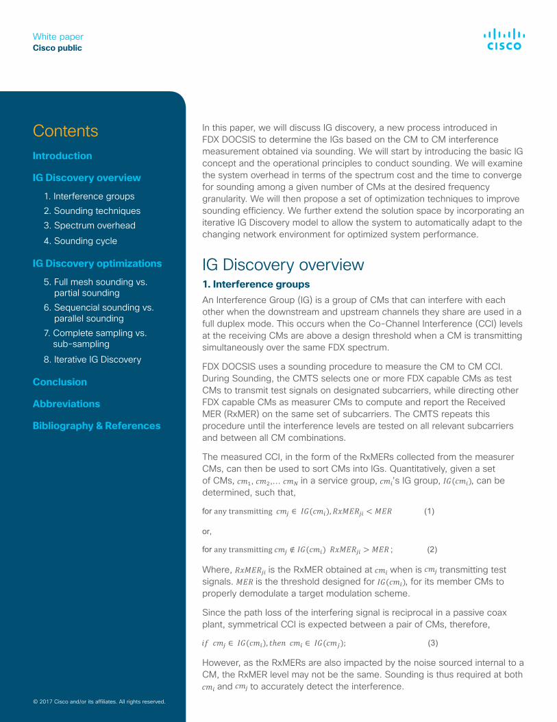
The measured CCI, in the form of the RxMERs collected from the measurer CMs, can then be used to sort CMs into IGs. Quantitatively, given a set of CMs, in a service group, ’s IG group, , can be determined, such that,
Where, is the RxMER obtained at when is transmitting test signals. is the threshold designed for , for its member CMs to properly demodulate a target modulation scheme.
Since the path loss of the interfering signal is reciprocal in a passive coax plant, symmetrical CCI is expected between a pair of CMs, therefore,
However, as the RxMERs are also impacted by the noise sourced internal to a CM, the RxMER level may not be the same. Sounding is thus required at both
and to accurately detect the interference.
White paperCisco public
© 2017 Cisco and/or its affiliates. All rights reserved.
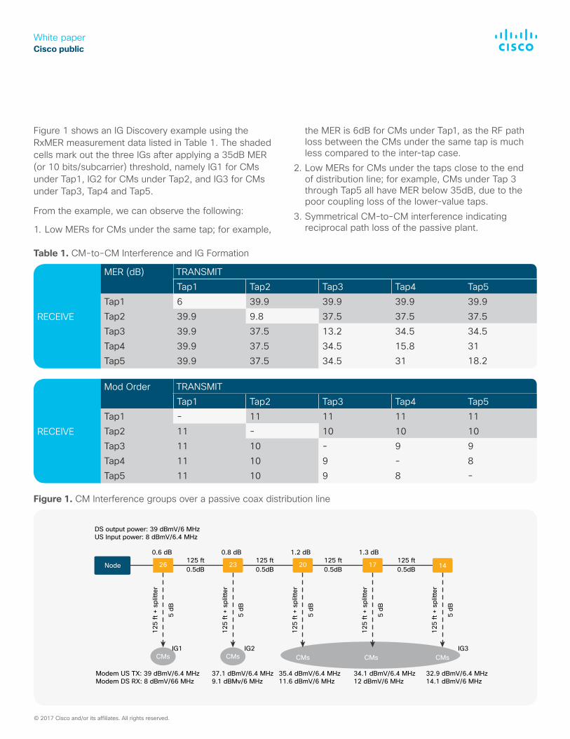
Figure 1 shows an IG Discovery example using the RxMER measurement data listed in Table 1. The shaded cells mark out the three IGs after applying a 35dB MER (or 10 bits/subcarrier) threshold, namely IG1 for CMs under Tap1, IG2 for CMs under Tap2, and IG3 for CMs under Tap3, Tap4 and Tap5.
From the example, we can observe the following:
1. Low MERs for CMs under the same tap; for example,
the MER is 6dB for CMs under Tap1, as the RF path loss between the CMs under the same tap is much less compared to the inter-tap case.
2. Low MERs for CMs under the taps close to the end of distribution line; for example, CMs under Tap 3 through Tap5 all have MER below 35dB, due to the poor coupling loss of the lower-value taps.
3. Symmetrical CM-to-CM interference indicating reciprocal path loss of the passive plant.
Table 1. CM-to-CM Interference and IG Formation
125
ft +
split
ter
5 dB
DS output power: 39 dBmV/6 MHzUS Input power: 8 dBmV/6.4 MHz
Modem US TX: 39 dBmV/6.4 MHzModem DS RX: 8 dBmV/66 MHz
37.1 dBmV/6.4 MHz9.1 dBMv/6 MHz
35.4 dBmV/6.4 MHz11.6 dBmV/6 MHz
34.1 dBmV/6.4 MHz12 dBmV/6 MHz
32.9 dBmV/6.4 MHz14.1 dBmV/6 MHz
125
ft +
split
ter
5 dB
0.6 dB
23 20 17 14Node
0.8 dB125 ft0.5dB
CMsIG1 IG2 IG3
CMs CMs CMs CMs
125 ft0.5dB
125 ft0.5dB
125 ft0.5dB
1.2 dB 1.3 dB
125
ft +
split
ter
5 dB
125
ft +
split
ter
5 dB
125
ft +
split
ter
5 dB
26
Figure 1. CM Interference groups over a passive coax distribution line
RECEIVE
MER (dB)Tap1 Tap2 Tap3 Tap4 Tap5
Tap1 6 39.9 39.9 39.9 39.9 Tap2 39.9 9.8 37.5 37.5 37.5 Tap3 39.9 37.5 13.2 34.5 34.5 Tap4 39.9 37.5 34.5 15.8 31 Tap5 39.9 37.5 34.5 31
RECEIVE
Mod OrderTap1 Tap2 Tap3 Tap4 Tap5
Tap1 - 11 11 11 11Tap2 11 - 10 10 10Tap3 11 10 - 9 9Tap4 11 10 9 - 8Tap5 11 10 9 8 -
TRANSMIT
TRANSMIT
18.2
-
White paperCisco public
2. Sounding techniquesThere are two sounding methods proposed in FDX DOCSIS [3][4].
1. Sounding with OFDMA Upstream Data Profile (OUDP) test bursts
2. Sounding with Continuous Wave (CW) test signals
The OUDP method is intended for the deployment scenario where the legacy high-split DOCSIS 3.1 CMs, after necessary software upgrade, can share the US spectrum between 108 to 204 MHz with the FDX CMs. Since the DOCSIS 3.1 CMs cannot generate a multiplicity of CW tones as required in the CW sounding method, the DOCSIS 3.1 OUDP test bursts must be used instead as the test signals. When the OUDP test bursts are being transmitted by a test CM, other CMs that are capable to receive in this frequency band measure the RxMERs in the time and frequency encompassed by the continuous OUDP bursts. The OUDP test burst is intended to cover all DS subcarrier frequency locations by taking advantage of a faster RxMER measurement scheme to be implemented on the new FDX CMs.
The CW method is intended for the deployment scenario where the DOCSIS 3.1 CMs, after necessary software upgrade, can share the DS spectrum with FDX CMs. For example, a low-split or mid-split DOCSIS 3.1 CM can share the DS spectrum between 108 to 684 MHz, and a high-split DOCSIS 3.1 CM can share the DS spectrum between 258 to 684MHz. During CW sounding, one or multiple FDX test CMs send CW test signals at selected DS subcarrier frequency locations, while the rest of CMs, including both legacy D3.1 CMs and FDX CMs measure the MER using the DOCSIS 3.1 RxMER measurement method.
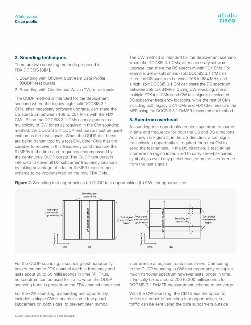
3. Spectrum overheadA sounding test opportunity requires spectrum resource in time and frequency for both the US and DS directions. As shown in Figure 2, in the US direction, a test signal transmission opportunity is required for a test CM to send the test signals. In the DS direction, a test signal interference region is required to carry zero-bit-loaded symbols, to avoid any packet caused by the interference from the test signals.
© 2017 Cisco and/or its affiliates. All rights reserved.
Figure 2. Sounding test opportunities (a) OUDP test opportunities (b) CW test opportunities
Time
(b)(a)
Sounding testopportunity
FDX
chan
nel s
pect
rumTest signal
transmissionopportunity
Freq
uenc
y
Freq
uenc
y
Time
Test signaltransmissionopportunity
Test signalinterference
region
Test signalinterference
regionSounding testopportunity
FDX
chan
nel s
pect
rum
For the OUDP sounding, a sounding test opportunity covers the entire FDX channel width in frequency and lasts about 20 to 60 milliseconds in time [4]. Thus, no spectrum can be used for traffic when the OUDP sounding burst is present on the FDX channel under test.
For the CW sounding, a sounding test opportunity includes a single CW subcarrier and a few guard subcarriers on both sides, to prevent inter-symbol
interference at adjacent data subcarriers. Comparing to the OUDP sounding, a CW test opportunity occupies much narrower spectrum however lasts longer in time. It typically takes around 200 to 300 milliseconds for DOCSIS 3.1 RxMER measurement scheme to converge.
With the CW sounding, the CMTS has the option to limit the number of sounding test opportunities, so traffic can be sent using the data subcarriers outside
White paperCisco public
the CW interference regions, particularly, the DS traffic to the measurer CMs, and the US traffic from a test CM if the test CM’s IGs have been identified through previous sounding.
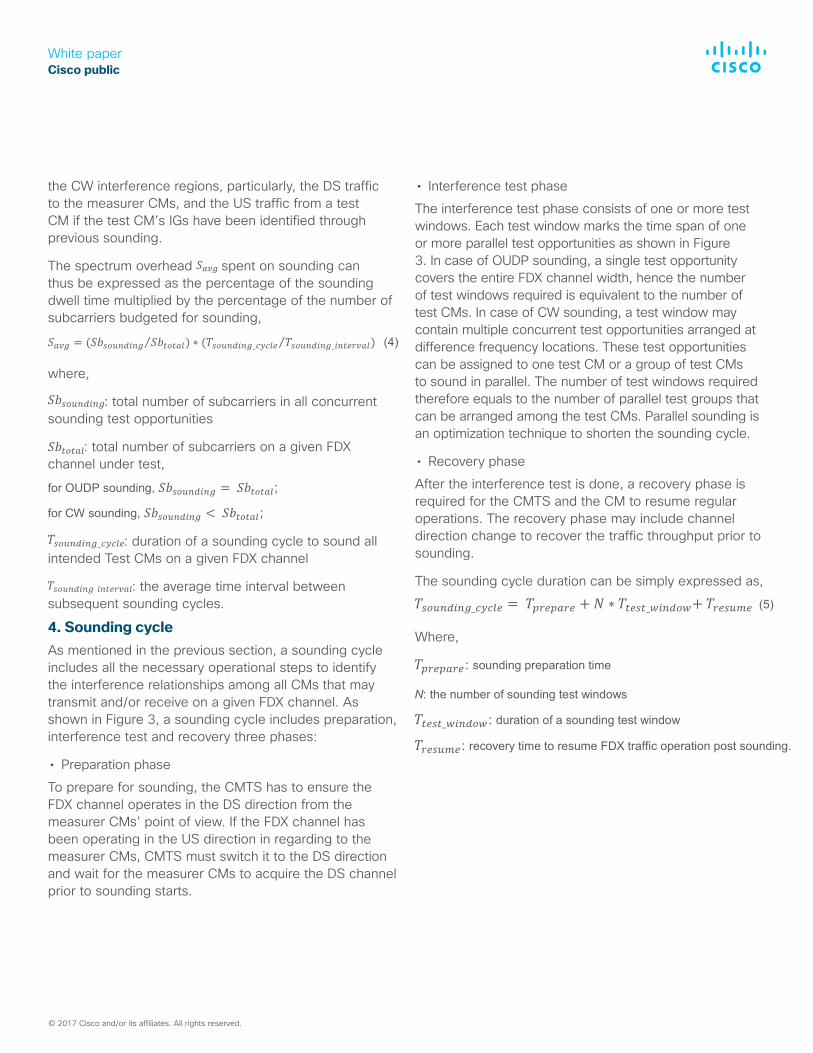
The spectrum overhead spent on sounding can thus be expressed as the percentage of the sounding dwell time multiplied by the percentage of the number of subcarriers budgeted for sounding,
where,
: total number of subcarriers in all concurrent sounding test opportunities
: total number of subcarriers on a given FDX channel under test,
: duration of a sounding cycle to sound all intended Test CMs on a given FDX channel
: the average time interval between subsequent sounding cycles.
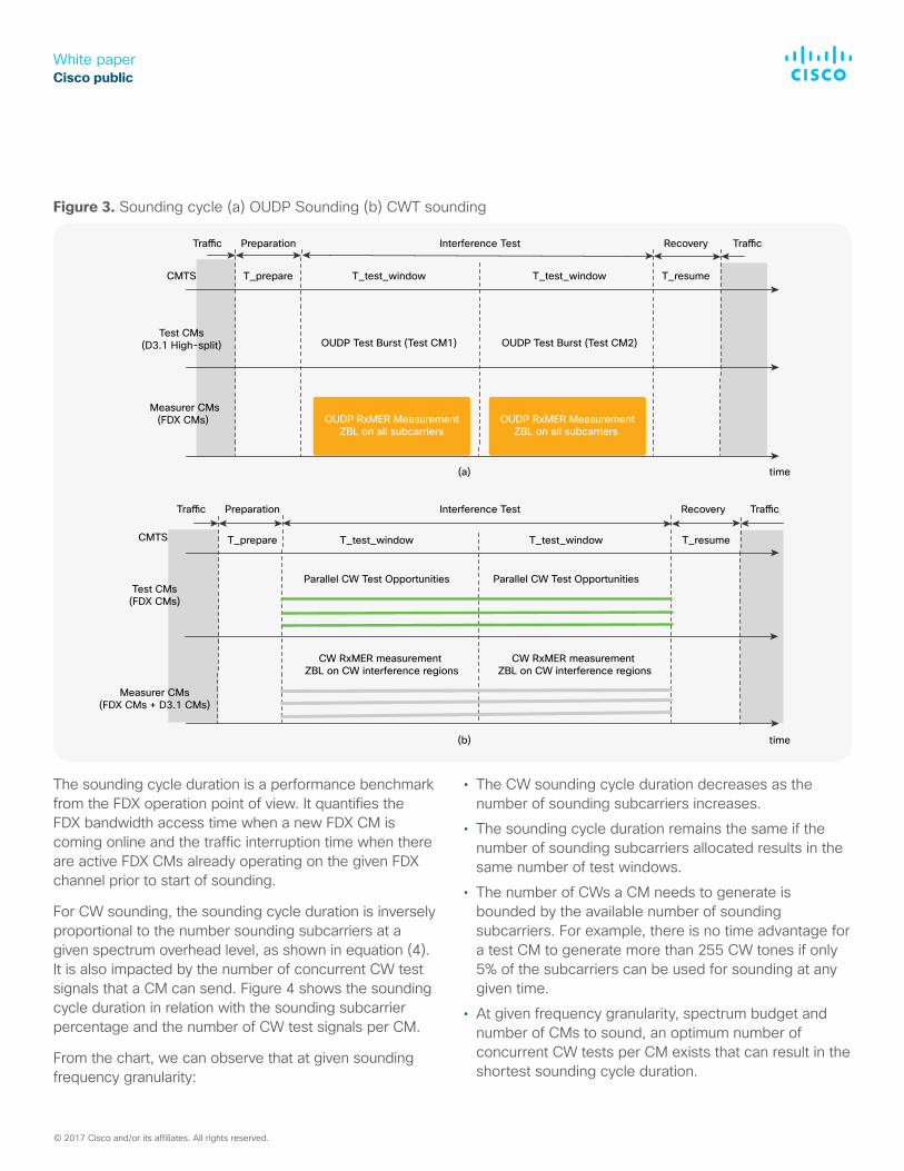
4. Sounding cycleAs mentioned in the previous section, a sounding cycle includes all the necessary operational steps to identify the interference relationships among all CMs that may transmit and/or receive on a given FDX channel. As shown in Figure 3, a sounding cycle includes preparation, interference test and recovery three phases:
• Preparation phaseTo prepare for sounding, the CMTS has to ensure the FDX channel operates in the DS direction from the measurer CMs’ point of view. If the FDX channel has been operating in the US direction in regarding to the measurer CMs, CMTS must switch it to the DS direction and wait for the measurer CMs to acquire the DS channel prior to sounding starts.
• Interference test phaseThe interference test phase consists of one or more test windows. Each test window marks the time span of one or more parallel test opportunities as shown in Figure 3. In case of OUDP sounding, a single test opportunity covers the entire FDX channel width, hence the number of test windows required is equivalent to the number of test CMs. In case of CW sounding, a test window may contain multiple concurrent test opportunities arranged at difference frequency locations. These test opportunities can be assigned to one test CM or a group of test CMs to sound in parallel. The number of test windows required therefore equals to the number of parallel test groups that can be arranged among the test CMs. Parallel sounding is an optimization technique to shorten the sounding cycle.
• Recovery phaseAfter the interference test is done, a recovery phase is required for the CMTS and the CM to resume regular operations. The recovery phase may include channel direction change to recover the traffic throughput prior to sounding.
The sounding cycle duration can be simply expressed as,
Where,
© 2017 Cisco and/or its affiliates. All rights reserved.
White paperCisco public
Figure 3. Sounding cycle (a) OUDP Sounding (b) CWT sounding
time
CMTS
(a)
time(b)
Traffic Preparation Interference Test Recovery Traffic
Traffic Preparation Interference Test Recovery Traffic
CMTS T_prepare T_resumeT_test_window
OUDP Test Burst (Test CM1)
OUDP RxMER MeasurementZBL on all subcarriers
OUDP RxMER MeasurementZBL on all subcarriers
OUDP Test Burst (Test CM2)
T_test_window
T_prepare T_resumeT_test_window T_test_window
Parallel CW Test Opportunities Parallel CW Test Opportunities
CW RxMER measurement ZBL on CW interference regions
CW RxMER measurement ZBL on CW interference regions
Test CMs(D3.1 High-split)
Test CMs(FDX CMs)
Measurer CMs(FDX CMs + D3.1 CMs)
Measurer CMs (FDX CMs)
The sounding cycle duration is a performance benchmark from the FDX operation point of view. It quantifies the FDX bandwidth access time when a new FDX CM is coming online and the traffic interruption time when there are active FDX CMs already operating on the given FDX channel prior to start of sounding.
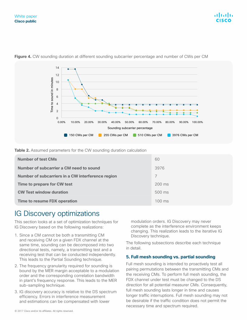
For CW sounding, the sounding cycle duration is inversely proportional to the number sounding subcarriers at a given spectrum overhead level, as shown in equation (4). It is also impacted by the number of concurrent CW test signals that a CM can send. Figure 4 shows the sounding cycle duration in relation with the sounding subcarrier percentage and the number of CW test signals per CM.
From the chart, we can observe that at given sounding frequency granularity:
• The CW sounding cycle duration decreases as the number of sounding subcarriers increases.
• The sounding cycle duration remains the same if the number of sounding subcarriers allocated results in the same number of test windows.
• The number of CWs a CM needs to generate is bounded by the available number of sounding subcarriers. For example, there is no time advantage for a test CM to generate more than 255 CW tones if only 5% of the subcarriers can be used for sounding at any given time.
• At given frequency granularity, spectrum budget and number of CMs to sound, an optimum number of concurrent CW tests per CM exists that can result in the shortest sounding cycle duration.
© 2017 Cisco and/or its affiliates. All rights reserved.
White paperCisco public
Figure 4. CW sounding duration at different sounding subcarrier percentage and number of CWs per CM
Table 2. Assumed parameters for the CW sounding duration calculation
14
12
10
8
6
4
2
0
Tim
e to
sou
nd in
min
utes
Sounding subcarrier percentage
150 CWs per CM 255 CWs per CM 510 CWs per CM 3976 CWs per CM
0.00% 10.00% 20.00% 30.00% 40.00% 50.00% 60.00% 70.00% 80.00% 90.00% 100.00%
IG Discovery optimizationsThis section looks at a set of optimization techniques for IG Discovery based on the following realizations:
1. Since a CM cannot be both a transmitting CM and receiving CM on a given FDX channel at the same time, sounding can be decomposed into two directional tests, namely, a transmitting test and a receiving test that can be conducted independently. This leads to the Partial Sounding technique.
2. The frequency granularity required for sounding is bound by the MER margin acceptable to a modulation order and the corresponding correlation bandwidth in plant’s frequency response. This leads to the MER sub-sampling technique.
3. IG discovery accuracy is relative to the DS spectrum efficiency. Errors in interference measurement and estimations can be compensated with lower
modulation orders. IG Discovery may never complete as the interference environment keeps changing. This realization leads to the iterative IG Discovery technique.
The following subsections describe each technique in detail.
5. Full mesh sounding vs. partial soundingFull mesh sounding is intended to proactively test all pairing permutations between the transmitting CMs and the receiving CMs. To perform full mesh sounding, the FDX channel under test must be changed to the DS direction for all potential measurer CMs. Consequently, full mesh sounding lasts longer in time and causes longer traffic interruptions. Full mesh sounding may not be desirable if the traffic condition does not permit the necessary time and spectrum required.
Number of test CMs 60
Number of subcarrier a CM need to sound 3976
Number of subcarriers in a CW interference region 7
Time to prepare for CW test 200 ms
CW Test window duration 500 ms
Time to resume FDX operation 100 ms
© 2017 Cisco and/or its affiliates. All rights reserved.
White paperCisco public
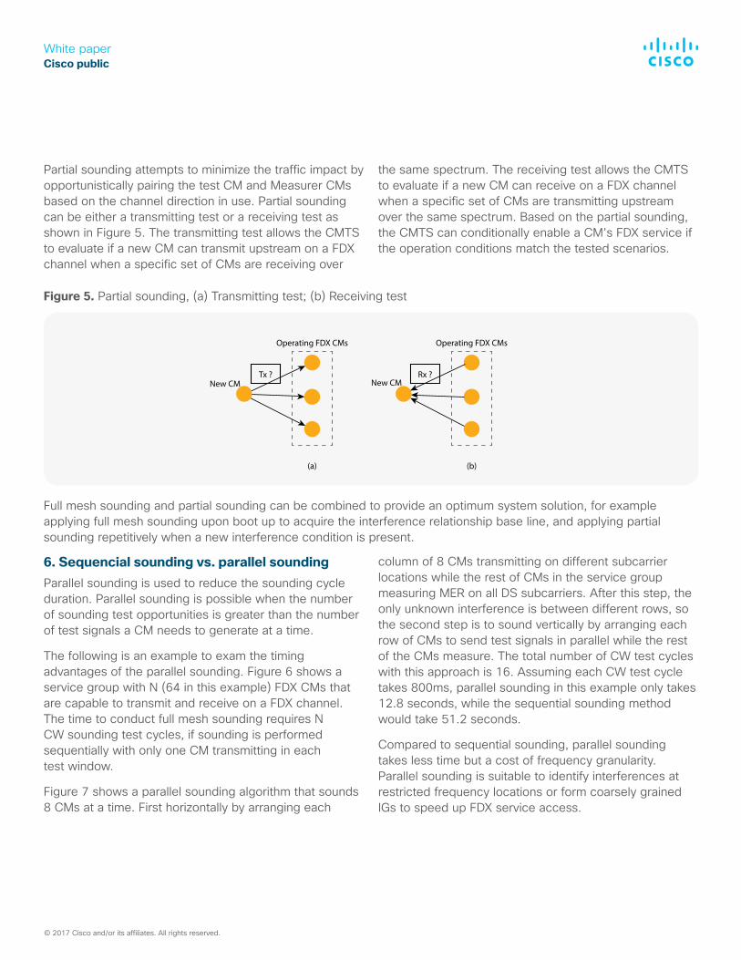
Figure 5. Partial sounding, (a) Transmitting test; (b) Receiving test
Operating FDX CMs Operating FDX CMs
Tx ? Rx ?
(a) (b)
New CM New CM
Full mesh sounding and partial sounding can be combined to provide an optimum system solution, for example applying full mesh sounding upon boot up to acquire the interference relationship base line, and applying partial sounding repetitively when a new interference condition is present.
Partial sounding attempts to minimize the traffic impact by opportunistically pairing the test CM and Measurer CMs based on the channel direction in use. Partial sounding can be either a transmitting test or a receiving test as shown in Figure 5. The transmitting test allows the CMTS to evaluate if a new CM can transmit upstream on a FDX channel when a specific set of CMs are receiving over
the same spectrum. The receiving test allows the CMTS to evaluate if a new CM can receive on a FDX channel when a specific set of CMs are transmitting upstream over the same spectrum. Based on the partial sounding, the CMTS can conditionally enable a CM’s FDX service if the operation conditions match the tested scenarios.
6. Sequencial sounding vs. parallel soundingParallel sounding is used to reduce the sounding cycle duration. Parallel sounding is possible when the number of sounding test opportunities is greater than the number of test signals a CM needs to generate at a time.
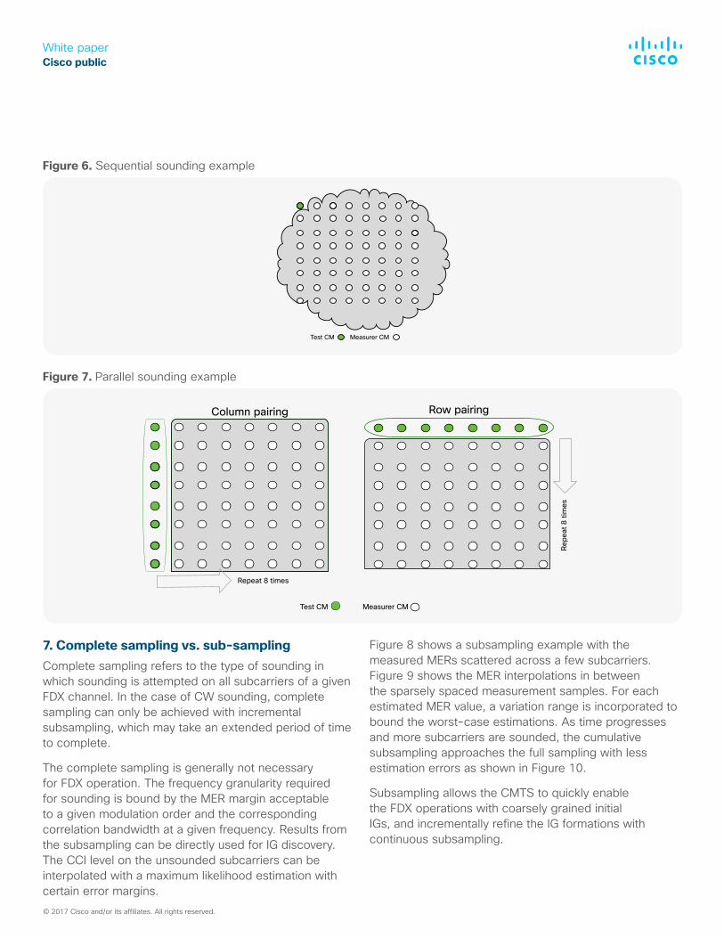
The following is an example to exam the timing advantages of the parallel sounding. Figure 6 shows a service group with N (64 in this example) FDX CMs that are capable to transmit and receive on a FDX channel. The time to conduct full mesh sounding requires N CW sounding test cycles, if sounding is performed sequentially with only one CM transmitting in each test window.
Figure 7 shows a parallel sounding algorithm that sounds 8 CMs at a time. First horizontally by arranging each
column of 8 CMs transmitting on different subcarrier locations while the rest of CMs in the service group measuring MER on all DS subcarriers. After this step, the only unknown interference is between different rows, so the second step is to sound vertically by arranging each row of CMs to send test signals in parallel while the rest of the CMs measure. The total number of CW test cycles with this approach is 16. Assuming each CW test cycle takes 800ms, parallel sounding in this example only takes 12.8 seconds, while the sequential sounding method would take 51.2 seconds.
Compared to sequential sounding, parallel sounding takes less time but a cost of frequency granularity. Parallel sounding is suitable to identify interferences at restricted frequency locations or form coarsely grained IGs to speed up FDX service access.
© 2017 Cisco and/or its affiliates. All rights reserved.
White paperCisco public
Figure 6. Sequential sounding example
Figure 7. Parallel sounding example
Test CM Measurer CM
Test CM Measurer CM
Repeat 8 times
Repe
at 8
tim
es
Row pairingColumn pairing
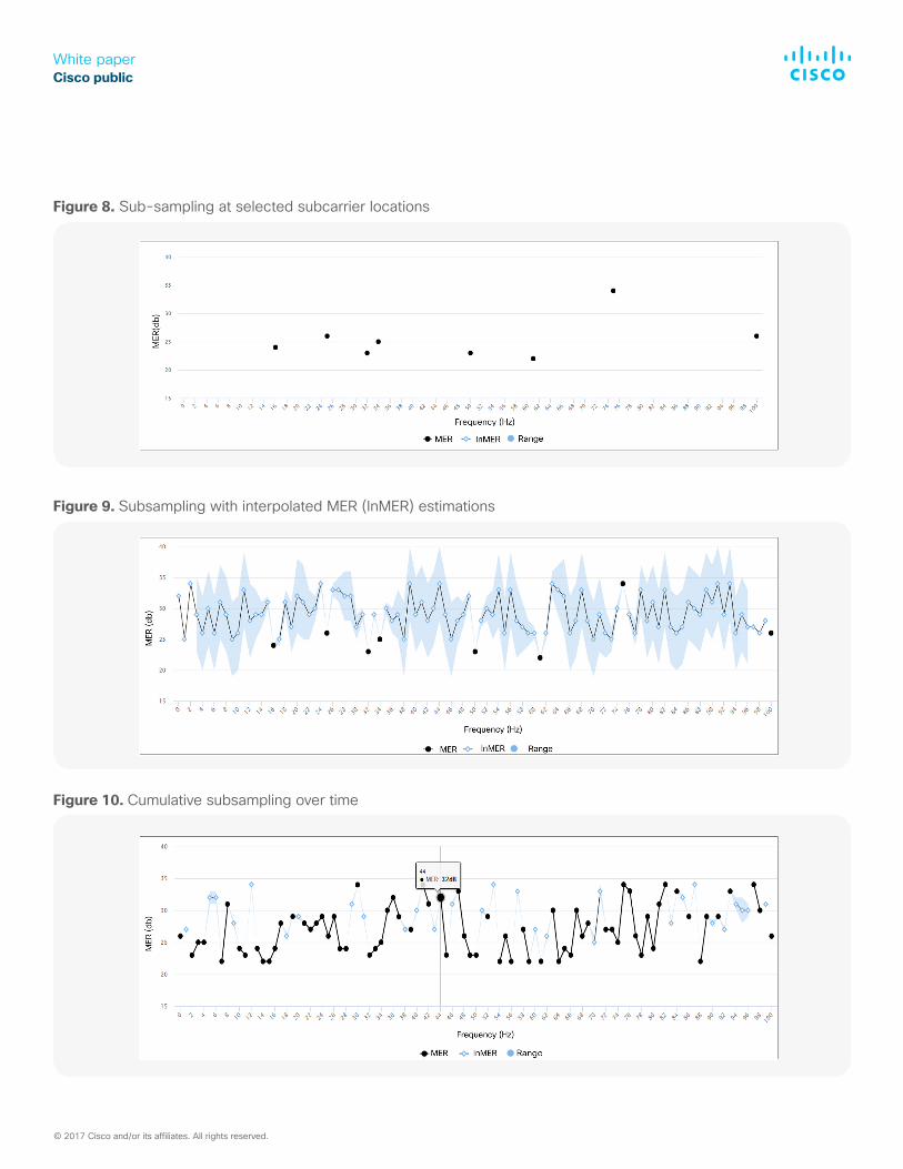
7. Complete sampling vs. sub-samplingComplete sampling refers to the type of sounding in which sounding is attempted on all subcarriers of a given FDX channel. In the case of CW sounding, complete sampling can only be achieved with incremental subsampling, which may take an extended period of time to complete.
The complete sampling is generally not necessary for FDX operation. The frequency granularity required for sounding is bound by the MER margin acceptable to a given modulation order and the corresponding correlation bandwidth at a given frequency. Results from the subsampling can be directly used for IG discovery. The CCI level on the unsounded subcarriers can be interpolated with a maximum likelihood estimation with certain error margins.
Figure 8 shows a subsampling example with the measured MERs scattered across a few subcarriers. Figure 9 shows the MER interpolations in between the sparsely spaced measurement samples. For each estimated MER value, a variation range is incorporated to bound the worst-case estimations. As time progresses and more subcarriers are sounded, the cumulative subsampling approaches the full sampling with less estimation errors as shown in Figure 10.
Subsampling allows the CMTS to quickly enable the FDX operations with coarsely grained initial IGs, and incrementally refine the IG formations with continuous subsampling.
© 2017 Cisco and/or its affiliates. All rights reserved.
White paperCisco public
Figure 8. Sub-sampling at selected subcarrier locations
Figure 9. Subsampling with interpolated MER (InMER) estimations
Figure 10. Cumulative subsampling over time
© 2017 Cisco and/or its affiliates. All rights reserved.
White paperCisco public
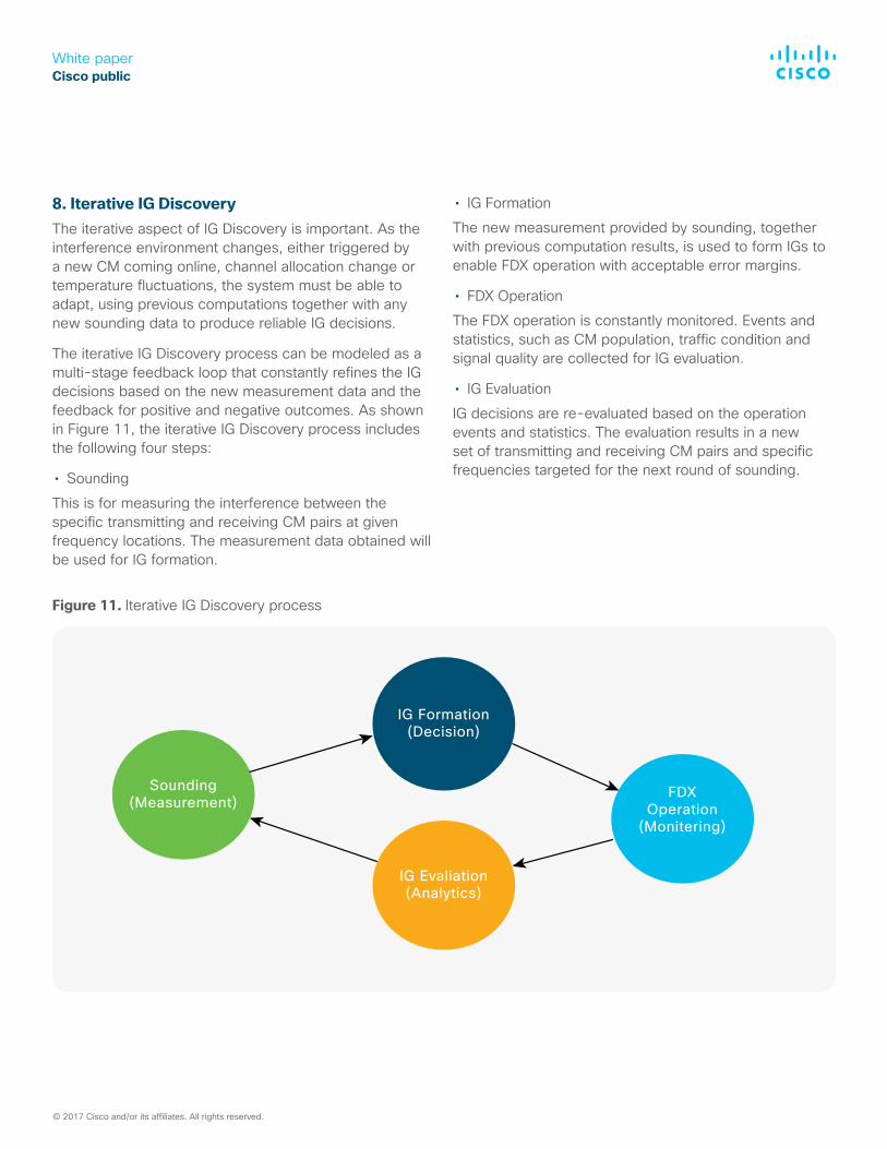
8. Iterative IG DiscoveryThe iterative aspect of IG Discovery is important. As the interference environment changes, either triggered by a new CM coming online, channel allocation change or temperature fluctuations, the system must be able to adapt, using previous computations together with any new sounding data to produce reliable IG decisions.
The iterative IG Discovery process can be modeled as a multi-stage feedback loop that constantly refines the IG decisions based on the new measurement data and the feedback for positive and negative outcomes. As shown in Figure 11, the iterative IG Discovery process includes the following four steps:
• SoundingThis is for measuring the interference between the specific transmitting and receiving CM pairs at given frequency locations. The measurement data obtained will be used for IG formation.
• IG FormationThe new measurement provided by sounding, together with previous computation results, is used to form IGs to enable FDX operation with acceptable error margins.
• FDX OperationThe FDX operation is constantly monitored. Events and statistics, such as CM population, traffic condition and signal quality are collected for IG evaluation.
• IG EvaluationIG decisions are re-evaluated based on the operation events and statistics. The evaluation results in a new set of transmitting and receiving CM pairs and specific frequencies targeted for the next round of sounding.
IG Formation(Decision)
FDXOperation
(Monitering)
IG Evaliation(Analytics)
Sounding(Measurement)
© 2017 Cisco and/or its affiliates. All rights reserved.
Figure 11. Iterative IG Discovery process
White paperCisco public
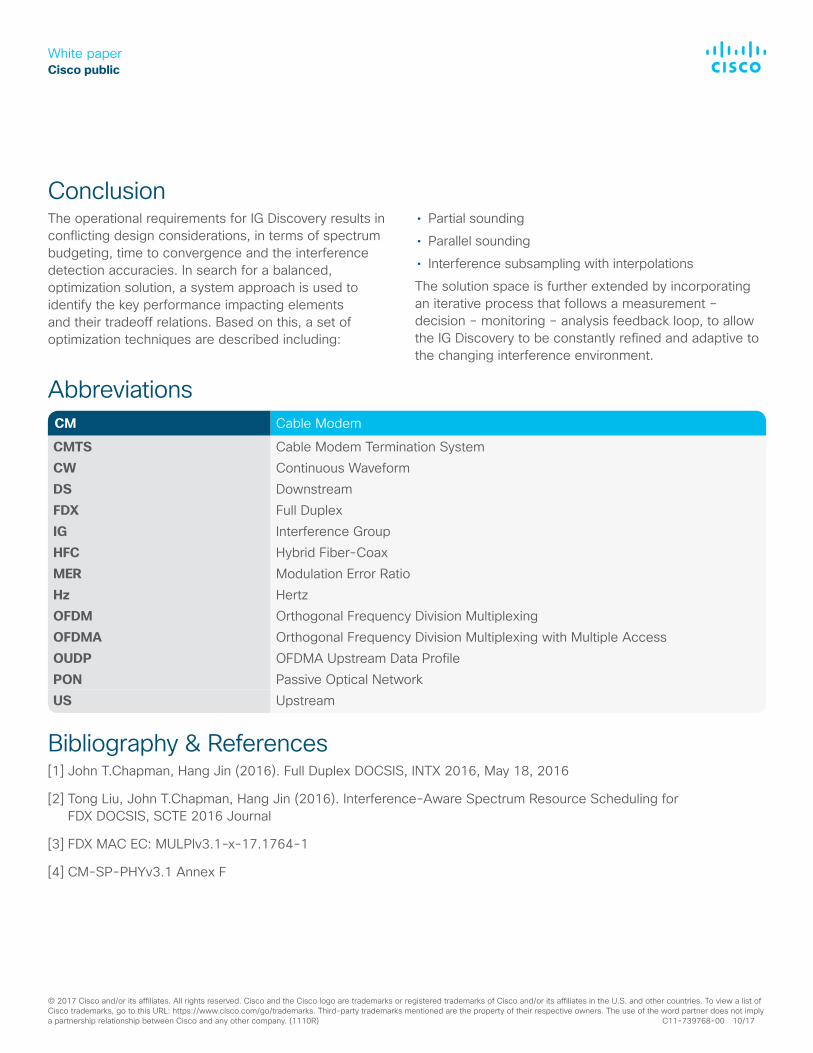
ConclusionThe operational requirements for IG Discovery results in conflicting design considerations, in terms of spectrum budgeting, time to convergence and the interference detection accuracies. In search for a balanced, optimization solution, a system approach is used to identify the key performance impacting elements and their tradeoff relations. Based on this, a set of optimization techniques are described including:
• Partial sounding• Parallel sounding• Interference subsampling with interpolationsThe solution space is further extended by incorporating an iterative process that follows a measurement – decision – monitoring – analysis feedback loop, to allow the IG Discovery to be constantly refined and adaptive to the changing interference environment.
AbbreviationsCM Cable Modem
CMTS Cable Modem Termination System CW Continuous Waveform DS Downstream FDX Full Duplex IG Interference Group HFC Hybrid Fiber-Coax MER Modulation Error Ratio Hz Hertz OFDM Orthogonal Frequency Division Multiplexing OFDMA Orthogonal Frequency Division Multiplexing with Multiple Access OUDP OFDMA Upstream Data Profile PON Passive Optical Network US Upstream
Bibliography & References[1] John T.Chapman, Hang Jin (2016). Full Duplex DOCSIS, INTX 2016, May 18, 2016
[2] Tong Liu, John T.Chapman, Hang Jin (2016). Interference-Aware Spectrum Resource Scheduling for FDX DOCSIS, SCTE 2016 Journal
[3] FDX MAC EC: MULPIv3.1-x-17.1764-1
[4] CM-SP-PHYv3.1 Annex F
© 2017 Cisco and/or its affiliates. All rights reserved. Cisco and the Cisco logo are trademarks or registered trademarks of Cisco and/or its affiliates in the U.S. and other countries. To view a list of Cisco trademarks, go to this URL: https://www.cisco.com/go/trademarks. Third-party trademarks mentioned are the property of their respective owners. The use of the word partner does not imply a partnership relationship between Cisco and any other company. (1110R) C11-739768-00 10/17