hydraulic pulse drilling - qwestoffice.netttinc10.qwestoffice.net/papers/gti-scng ii.pdf ·...
TRANSCRIPT
Presentation for GTI Natural Gas Technologies II Conference, February 8-11 2004
Hydraulic Pulse Drilling
Jack Kolle President
Tempress Technologies Inc. Kent, WA 98032
U.S.A.
Abstract Slow penetration rates in deep, over-pressurized formations represent a critical challenge for gas drilling operations. Hydraulic pulse drilling is designed to increase overbalanced drilling rates by generating suction pulses at the drill bit and by fluidizing the drillstring. A self-actuated valve is deployed above the bit in a high-speed flow course housing. Stopping the flow of mud through the flow courses generates a series of intense suction pulses around the bit. Pressure drilling tests in shale at high mud weight have verified increases in rate of penetration of 40% to 200% with roller cone bits. Field tests have demonstrated that the pulses provide active vibration control of improper bit motions. A sweep modulator has been added to the valve for seismic profiling and look-ahead seismic imaging-while drilling. The swept impulse signal has been used for seismic profiling and look ahead seismic imaging while drilling.
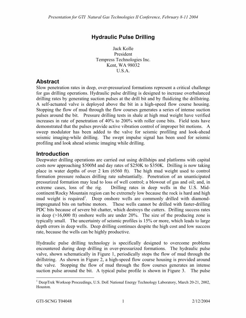
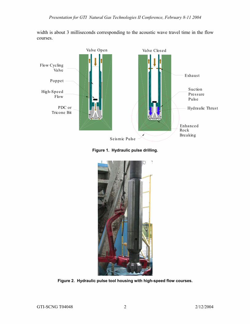
Introduction Deepwater drilling operations are carried out using drillships and platforms with capital costs now approaching $500M and day rates of $250K to $350K. Drilling is now taking place in water depths of over 2 km (6560 ft). The high mud weight used to control formation pressure reduces drilling rate substantially. Penetration of an unanticipated pressurized formation may lead to loss of well control; a blowout of gas and oil; and, in extreme cases, loss of the rig. Drilling rates in deep wells in the U.S. Mid-continent/Rocky Mountain region can be extremely low because the rock is hard and high mud weight is required1. Deep onshore wells are commonly drilled with diamond-impregnated bits on turbine motors. These wells cannot be drilled with faster-drilling PDC bits because of severe bit chatter, which destroys the cutters. Drilling success rates in deep (>16,000 ft) onshore wells are under 20%. The size of the producing zone is typically small. The uncertainty of seismic profiles is 15% or more, which leads to large depth errors in deep wells. Deep drilling continues despite the high cost and low success rate, because the wells can be highly productive. Hydraulic pulse drilling technology is specifically designed to overcome problems encountered during deep drilling in over-pressurized formations. The hydraulic pulse valve, shown schematically in Figure 1, periodically stops the flow of mud through the drillstring. As shown in Figure 2, a high-speed flow course housing is provided around the valve. Stopping the flow of mud through the flow courses generates an intense suction pulse around the bit. A typical pulse profile is shown in Figure 3. The pulse 1 DeepTrek Worksop Proceedings, U.S. DoE National Energy Technology Laboratory, March 20-21, 2002, Houston.
GTI-SCNG T04048 1 2/12/2004
Presentation for GTI Natural Gas Technologies II Conference, February 8-11 2004
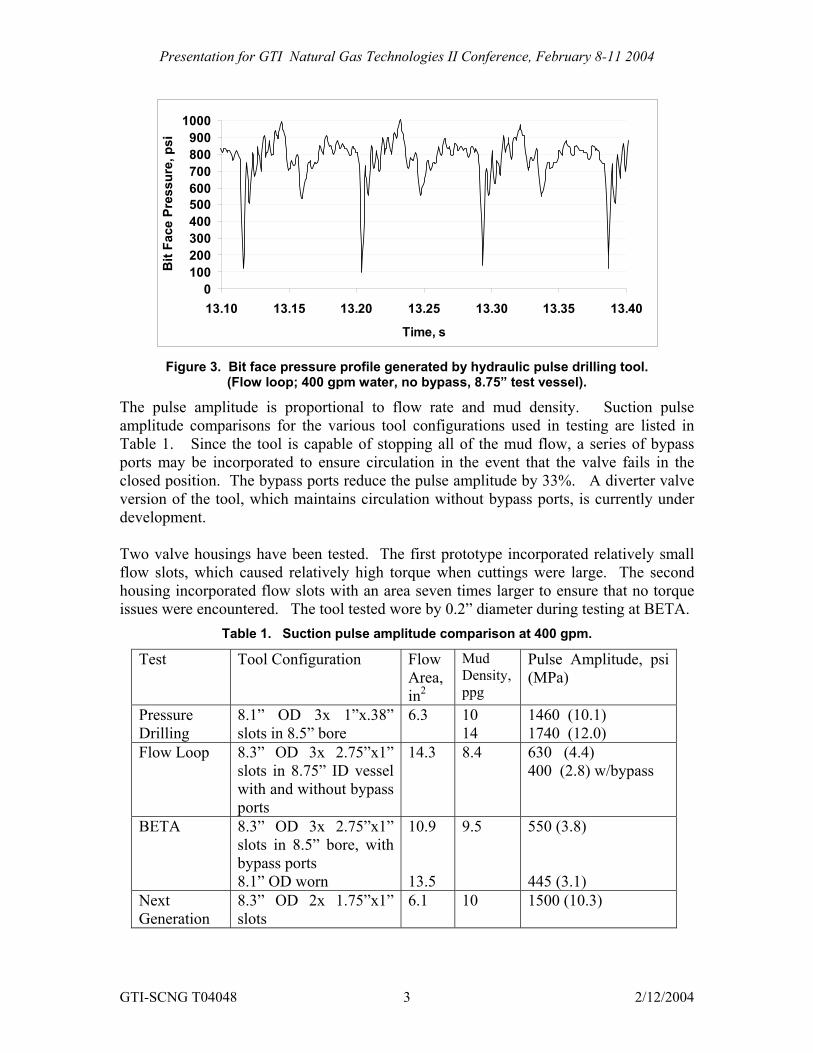
width is about 3 milliseconds corresponding to the acoustic wave travel time in the flow courses.
Valve Open Valve Closed
Enhanced
Seismic Pulse
PDC orTricone Bit
Flow CyclingValve
High-SpeedFlow
Poppet
Rock Breaking
Pulse
Hydraulic Thrus t
PressureSuction
Exhaus t
Figure 1. Hydraulic pulse drilling.
Figure 2. Hydraulic pulse tool housing with high-speed flow courses.
GTI-SCNG T04048 2 2/12/2004
Presentation for GTI Natural Gas Technologies II Conference, February 8-11 2004
0100200300400500600700800900
1000
13.10 13.15 13.20 13.25 13.30 13.35 13.40
Time, s
Bit
Face
Pre
ssur
e, p
si
Figure 3. Bit face pressure profile generated by hydraulic pulse drilling tool.
(Flow loop; 400 gpm water, no bypass, 8.75” test vessel).
The pulse amplitude is proportional to flow rate and mud density. Suction pulse amplitude comparisons for the various tool configurations used in testing are listed in Table 1. Since the tool is capable of stopping all of the mud flow, a series of bypass ports may be incorporated to ensure circulation in the event that the valve fails in the closed position. The bypass ports reduce the pulse amplitude by 33%. A diverter valve version of the tool, which maintains circulation without bypass ports, is currently under development. Two valve housings have been tested. The first prototype incorporated relatively small flow slots, which caused relatively high torque when cuttings were large. The second housing incorporated flow slots with an area seven times larger to ensure that no torque issues were encountered. The tool tested wore by 0.2” diameter during testing at BETA.
Table 1. Suction pulse amplitude comparison at 400 gpm.
Test Tool Configuration Flow Area, in2
Mud Density, ppg
Pulse Amplitude, psi (MPa)
Pressure Drilling
8.1” OD 3x 1”x.38” slots in 8.5” bore
6.3 10 14
1460 (10.1) 1740 (12.0)
Flow Loop 8.3” OD 3x 2.75”x1” slots in 8.75” ID vessel with and without bypass ports
14.3 8.4
630 (4.4) 400 (2.8) w/bypass
BETA 8.3” OD 3x 2.75”x1” slots in 8.5” bore, with bypass ports 8.1” OD worn
10.9 13.5
9.5
550 (3.8) 445 (3.1)
Next Generation
8.3” OD 2x 1.75”x1” slots
6.1 10 1500 (10.3)
GTI-SCNG T04048 3 2/12/2004
Presentation for GTI Natural Gas Technologies II Conference, February 8-11 2004
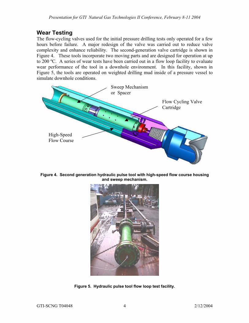
Wear Testing The flow-cycling valves used for the initial pressure drilling tests only operated for a few hours before failure. A major redesign of the valve was carried out to reduce valve complexity and enhance reliability. The second-generation valve cartridge is shown in Figure 4. These tools incorporate two moving parts and are designed for operation at up to 200 ºC. A series of wear tests have been carried out in a flow loop facility to evaluate wear performance of the tool in a downhole environment. In this facility, shown in Figure 5, the tools are operated on weighted drilling mud inside of a pressure vessel to simulate downhole conditions.
Sweep Mechanismor Spacer
Flow Cycling ValveCartridge
High-Speed Flow Course
Figure 4. Second generation hydraulic pulse tool with high-speed flow course housing and sweep mechanism.
Figure 5. Hydraulic pulse tool flow loop test facility.
GTI-SCNG T04048 4 2/12/2004
Presentation for GTI Natural Gas Technologies II Conference, February 8-11 2004
Component wear screening tests are ongoing to identify materials capable of continuous operation for 100 hours. Critical moving valve components are tested for 5 hours and inspected. The tests have included over 24 hours of down hole drilling operations. Valve components capable of operation for 5 hours with no appreciable wear have been identified and a 100-hour test is planned. The seismic sweep mechanism has been operated for over 5 hours – primarily downhole while drilling with no appreciable wear.
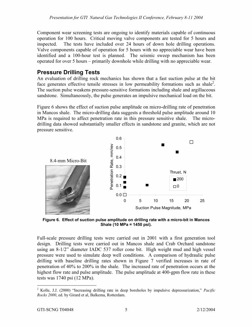
Pressure Drilling Tests An evaluation of drilling rock mechanics has shown that a fast suction pulse at the bit face generates effective tensile stresses in low permeability formations such as shale2. The suction pulse weakens pressure-sensitive formations including shale and argillaceous sandstone. Simultaneously, the pulse generates an impulsive mechanical load on the bit. Figure 6 shows the effect of suction pulse amplitude on micro-drilling rate of penetration in Mancos shale. The micro-drilling data suggests a threshold pulse amplitude around 10 MPa is required to affect penetration rate in this pressure sensitive shale. The micro-drilling data showed substantially smaller effects in sandstone and granite, which are not pressure sensitive.
0.3
0.4
0.5
0.6
Rat
e, m
m/re
v
Fig
Full-sdesigusingpressdrillinpenethighetests
GTI-S
2 KollRocks
8.4-mm Micro-Bit
0.0
0.1
0.2
0 5 10 15 20 25
Suction Pulse Magnitude, MPa
Pen
etra
tion
200
0
Thrust, N
ure 6. Effect of suction pulse amplitude on drilling rate with a micro-bit in Mancos
Shale (10 MPa = 1450 psi).
cale pressure drilling tests were carried out in 2001 with a first generation tool n. Drilling tests were carried out in Mancos shale and Crab Orchard sandstone an 8-1/2” diameter IADC 537 roller cone bit. High weight mud and high vessel ure were used to simulate deep well conditions. A comparison of hydraulic pulse g with baseline drilling rates shown in Figure 7 verified increases in rate of
ration of 40% to 200% in the shale. The increased rate of penetration occurs at the st flow rate and pulse amplitude. The pulse amplitude at 400-gpm flow rate in these was 1740 psi (12 MPa).
CNG T04048 5 2/12/2004
e, J.J. (2000) “Increasing drilling rate in deep boreholes by impulsive depressurization,” Pacific 2000, ed. by Girard et al, Balkema, Rotterdam.
Presentation for GTI Natural Gas Technologies II Conference, February 8-11 2004
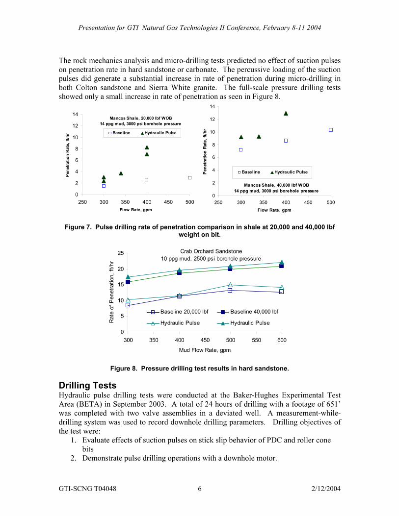
The rock mechanics analysis and micro-drilling tests predicted no effect of suction pulses on penetration rate in hard sandstone or carbonate. The percussive loading of the suction pulses did generate a substantial increase in rate of penetration during micro-drilling in both Colton sandstone and Sierra White granite. The full-scale pressure drilling tests showed only a small increase in rate of penetration as seen in Figure 8.
0
2
4
6
8
10
12
14
250 300 350 400 450 500Flow Rate, gpm
Pen
etra
tion
Rat
e, ft
/hr Baseline Hydraulic Pulse
Mancos Shale, 20,000 lbf WOB14 ppg mud, 3000 psi borehole pressure
0
2
4
6
8
10
12
14
250 300 350 400 450 500Flow Rate, gpm
Pene
tratio
n Ra
te, f
t/hr
Baseline Hydraulic Pulse
Mancos Shale, 40,000 lbf WOB14 ppg mud, 3000 psi borehole pressure
Figure 7. Pulse drilling rate of penetration comparison in shale at 20,000 and 40,000 lbf
weight on bit.
0
5
10
15
20
25
300 350 400 450 500 550 600
Mud Flow Rate, gpm
Rat
e of
Pen
etra
tion,
ft/h
r
Baseline 20,000 lbf Baseline 40,000 lbf
Hydraulic Pulse Hydraulic Pulse
Crab Orchard Sandstone10 ppg mud, 2500 psi borehole pressure
Figure 8. Pressure drilling test results in hard sandstone.
Drilling Tests Hydraulic pulse drilling tests were conducted at the Baker-Hughes Experimental Test Area (BETA) in September 2003. A total of 24 hours of drilling with a footage of 651’ was completed with two valve assemblies in a deviated well. A measurement-while-drilling system was used to record downhole drilling parameters. Drilling objectives of the test were:
1. Evaluate effects of suction pulses on stick slip behavior of PDC and roller cone bits
2. Demonstrate pulse drilling operations with a downhole motor.
GTI-SCNG T04048 6 2/12/2004
Presentation for GTI Natural Gas Technologies II Conference, February 8-11 2004
The drilling tests were carried out with a 20% bypass valve on the tool to ensure that flow circulation would be maintained in the event of valve failure in the closed position. The flow bypass reduces the suction pulse amplitude by 33%. The suction pulse amplitude during the drilling tests was 550 psi (3.8 MPa) at 400-gpm flow rate with 9.5-ppg mud.
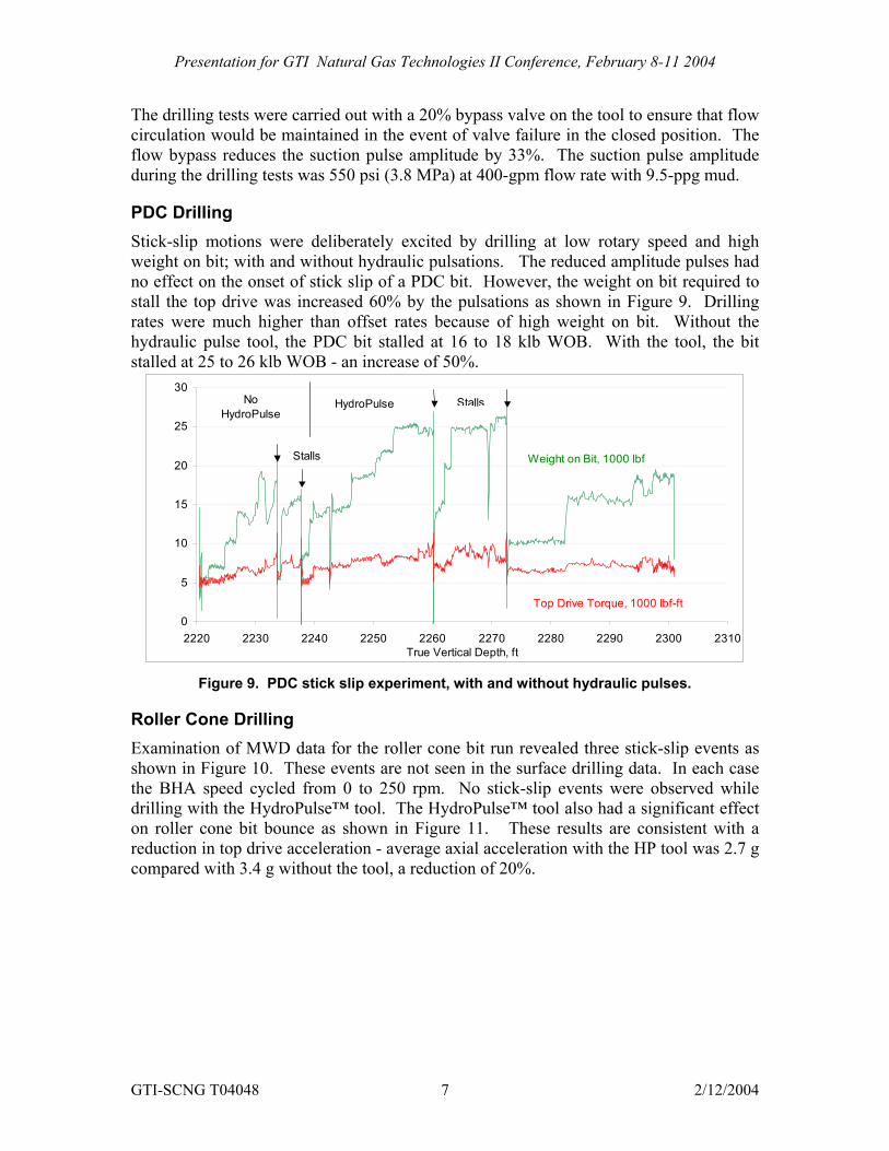
PDC Drilling Stick-slip motions were deliberately excited by drilling at low rotary speed and high weight on bit; with and without hydraulic pulsations. The reduced amplitude pulses had no effect on the onset of stick slip of a PDC bit. However, the weight on bit required to stall the top drive was increased 60% by the pulsations as shown in Figure 9. Drilling rates were much higher than offset rates because of high weight on bit. Without the hydraulic pulse tool, the PDC bit stalled at 16 to 18 klb WOB. With the tool, the bit stalled at 25 to 26 klb WOB - an increase of 50%.
0
5
10
15
20
25
30
2220 2230 2240 2250 2260 2270 2280 2290 2300 2310True Vertical Depth, ft
HydroPulseNo HydroPulse
Stalls
Stalls
Weight on Bit, 1000 lbf
Top Drive Torque, 1000 lbf-ft
Figure 9. PDC stick slip experiment, with and without hydraulic pulses.
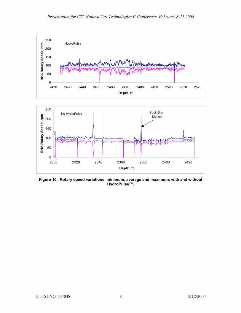
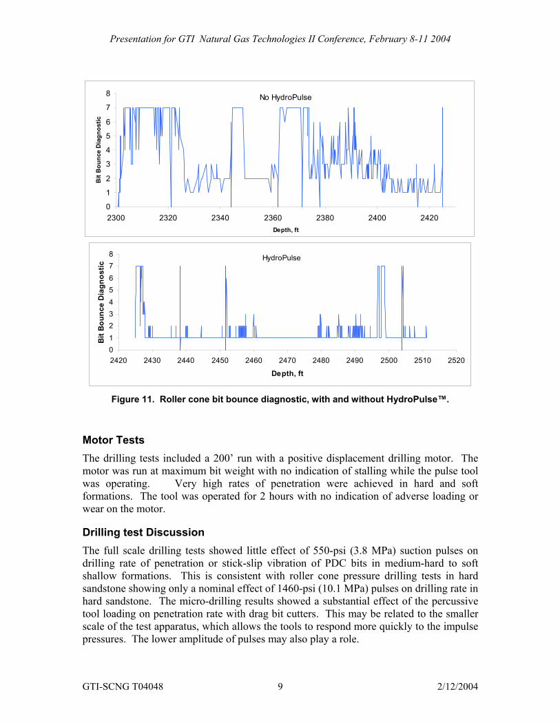
Roller Cone Drilling Examination of MWD data for the roller cone bit run revealed three stick-slip events as shown in Figure 10. These events are not seen in the surface drilling data. In each case the BHA speed cycled from 0 to 250 rpm. No stick-slip events were observed while drilling with the HydroPulse™ tool. The HydroPulse™ tool also had a significant effect on roller cone bit bounce as shown in Figure 11. These results are consistent with a reduction in top drive acceleration - average axial acceleration with the HP tool was 2.7 g compared with 3.4 g without the tool, a reduction of 20%.
GTI-SCNG T04048 7 2/12/2004
Presentation for GTI Natural Gas Technologies II Conference, February 8-11 2004
0
50
100
150
200
250
2420 2430 2440 2450 2460 2470 2480 2490 2500 2510 2520
Depth, ft
BH
A R
otar
y Sp
eed,
rpm HydroPulse
0
50
100
150
200
250
2300 2320 2340 2360 2380 2400 2420
Depth, ft
BH
A R
otar
y Sp
eed,
rpm
Stick-Slip Motion
No-HydroPulse
Figure 10. Rotary speed variations, minimum, average and maximum; with and without
HydroPulse™.
GTI-SCNG T04048 8 2/12/2004
Presentation for GTI Natural Gas Technologies II Conference, February 8-11 2004
0
1
2
3
4
5
6
7
8
2300 2320 2340 2360 2380 2400 2420Depth, ft
Bit
Bou
nce
Dia
gnos
ticNo HydroPulse
012345678
2420 2430 2440 2450 2460 2470 2480 2490 2500 2510 2520
Depth, ft
Bit
Bou
nce
Dia
gnos
tic
HydroPulse
Figure 11. Roller cone bit bounce diagnostic, with and without HydroPulse™.
Motor Tests The drilling tests included a 200’ run with a positive displacement drilling motor. The motor was run at maximum bit weight with no indication of stalling while the pulse tool was operating. Very high rates of penetration were achieved in hard and soft formations. The tool was operated for 2 hours with no indication of adverse loading or wear on the motor.
Drilling test Discussion The full scale drilling tests showed little effect of 550-psi (3.8 MPa) suction pulses on drilling rate of penetration or stick-slip vibration of PDC bits in medium-hard to soft shallow formations. This is consistent with roller cone pressure drilling tests in hard sandstone showing only a nominal effect of 1460-psi (10.1 MPa) pulses on drilling rate in hard sandstone. The micro-drilling results showed a substantial effect of the percussive tool loading on penetration rate with drag bit cutters. This may be related to the smaller scale of the test apparatus, which allows the tools to respond more quickly to the impulse pressures. The lower amplitude of pulses may also play a role.
GTI-SCNG T04048 9 2/12/2004
Presentation for GTI Natural Gas Technologies II Conference, February 8-11 2004
It may be possible to enhance drilling performance in hard rock by decoupling the tool from the drill collars. The large mass of the drill collars reduces the motion of the bit in response to the hydraulic percussive load. A hydraulic thruster above the tool or motor would allow substantially faster tool response. Drilling hard formations may require a different housing configuration as well. A longer housing would provide longer duration pulses, providing more time for the bit to respond to the applied suction load.
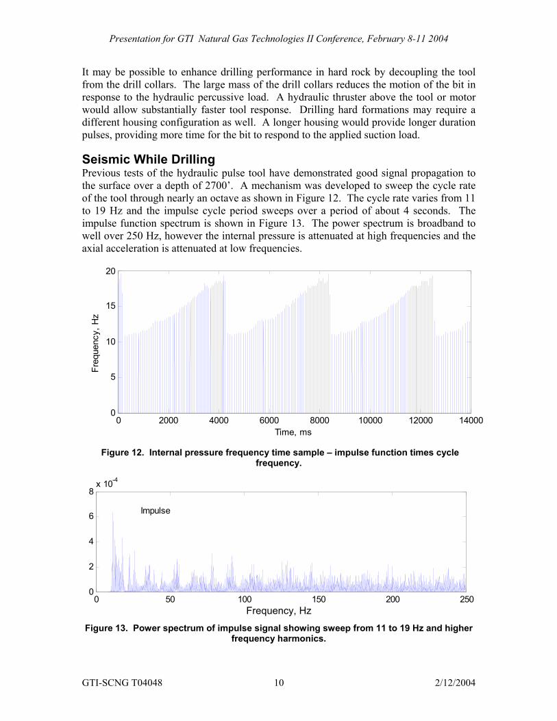
Seismic While Drilling Previous tests of the hydraulic pulse tool have demonstrated good signal propagation to the surface over a depth of 2700’. A mechanism was developed to sweep the cycle rate of the tool through nearly an octave as shown in Figure 12. The cycle rate varies from 11 to 19 Hz and the impulse cycle period sweeps over a period of about 4 seconds. The impulse function spectrum is shown in Figure 13. The power spectrum is broadband to well over 250 Hz, however the internal pressure is attenuated at high frequencies and the axial acceleration is attenuated at low frequencies.
0 2000 4000 6000 8000 10000 12000 140000
5
10
15
20
Time, ms
Freq
uenc
y, H
z
Figure 12. Internal pressure frequency time sample – impulse function times cycle
frequency.
0 50 100 150 200 2500
2
4
6
8x 10⁻⁴
Impulse
Frequency, Hz
Figure 13. Power spectrum of impulse signal showing sweep from 11 to 19 Hz and higher frequency harmonics.
GTI-SCNG T04048 10 2/12/2004
Presentation for GTI Natural Gas Technologies II Conference, February 8-11 2004
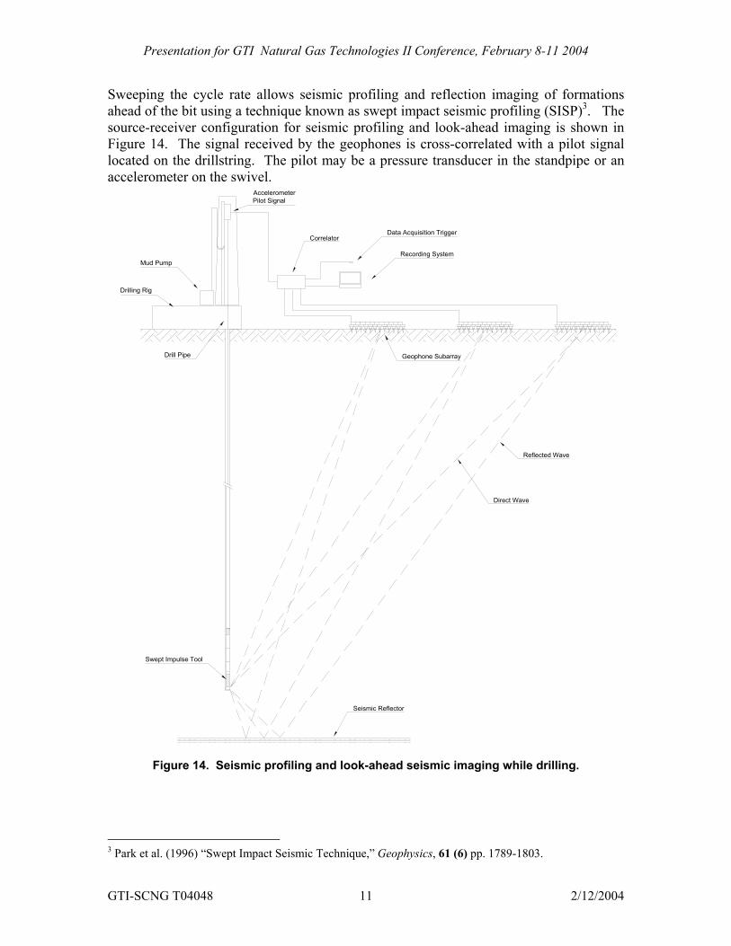
Sweeping the cycle rate allows seismic profiling and reflection imaging of formations ahead of the bit using a technique known as swept impact seismic profiling (SISP)3. The source-receiver configuration for seismic profiling and look-ahead imaging is shown in Figure 14. The signal received by the geophones is cross-correlated with a pilot signal located on the drillstring. The pilot may be a pressure transducer in the standpipe or an accelerometer on the swivel.
Correlator
Drilling Rig
Drill Pipe
Mud Pump
AccelerometerPilot Signal
Geophone Subarray
Data Acquisition Trigger
Recording System
Swept Impulse Tool
Reflected Wave
Direct Wave
Seismic Reflector
Figure 14. Seismic profiling and look-ahead seismic imaging while drilling.
3 Park et al. (1996) “Swept Impact Seismic Technique,” Geophysics, 61 (6) pp. 1789-1803.
GTI-SCNG T04048 11 2/12/2004
Presentation for GTI Natural Gas Technologies II Conference, February 8-11 2004
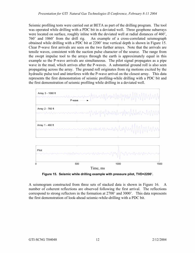
Seismic profiling tests were carried out at BETA as part of the drilling program. The tool was operated while drilling with a PDC bit in a deviated well. Three geophone subarrays were located on surface, roughly inline with the deviated well at radial distances of 460’, 760’ and 1060’ from the drill rig. An example of a cross-correlated seismograph obtained while drilling with a PDC bit at 2200’ true vertical depth is shown in Figure 15. Clear P-wave first arrivals are seen on the two further arrays. Note that the arrivals are tensile waves, consistent with the suction pulse character of the source. The range from the swept impulse tool to the arrays through the earth is approximately equal in this example so the P-wave arrivals are simultaneous. The pilot signal propagates as a pipe wave in the mud, which arrives after the P-waves. A substantial ground roll is also seen propagating across the array. The ground roll originates from rig motions excited by the hydraulic pulse tool and interferes with the P-wave arrival on the closest array. This data represents the first demonstration of seismic profiling-while drilling with a PDC bit and the first demonstration of seismic profiling while drilling in a deviated well.
0 500 1000 1500
Pilot
Array 1 - 460 ft
Array 2 - 760 ft
Array 3 - 1060 ft
P-wave
Time, ms Figure 15. Seismic while drilling example with pressure pilot, TVD=2200’.
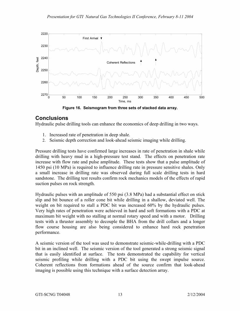
A seismogram constructed from three sets of stacked data is shown in Figure 16. A number of coherent reflections are observed following the first arrival. The reflections correspond to strong reflectors in the formation at 2700’ and 3000’. This data represents the first demonstration of look-ahead seismic-while-drilling with a PDC bit.
GTI-SCNG T04048 12 2/12/2004
Presentation for GTI Natural Gas Technologies II Conference, February 8-11 2004
0 50 100 150 200 250 300 350 400 450 500
2220
2230
2240
2250
2260
2270
Time, ms
Dep
th, f
eet
First Arrival
Coherent Reflections
Figure 16. Seismogram from three sets of stacked data array.
Conclusions Hydraulic pulse drilling tools can enhance the economics of deep drilling in two ways.
1. Increased rate of penetration in deep shale. 2. Seismic depth correction and look-ahead seismic imaging while drilling.
Pressure drilling tests have confirmed large increases in rate of penetration in shale while drilling with heavy mud in a high-pressure test stand. The effects on penetration rate increase with flow rate and pulse amplitude. These tests show that a pulse amplitude of 1450 psi (10 MPa) is required to influence drilling rate in pressure sensitive shales. Only a small increase in drilling rate was observed during full scale drilling tests in hard sandstone. The drilling test results confirm rock mechanics models of the effects of rapid suction pulses on rock strength. Hydraulic pulses with an amplitude of 550 psi (3.8 MPa) had a substantial effect on stick slip and bit bounce of a roller cone bit while drilling in a shallow, deviated well. The weight on bit required to stall a PDC bit was increased 60% by the hydraulic pulses. Very high rates of penetration were achieved in hard and soft formations with a PDC at maximum bit weight with no stalling at normal rotary speed and with a motor. Drilling tests with a thruster assembly to decouple the BHA from the drill collars and a longer flow course housing are also being considered to enhance hard rock penetration performance. A seismic version of the tool was used to demonstrate seismic-while-drilling with a PDC bit in an inclined well. The seismic version of the tool generated a strong seismic signal that is easily identified at surface. The tests demonstrated the capability for vertical seismic profiling while drilling with a PDC bit using the swept impulse source. Coherent reflections from formations ahead of the source confirm that look-ahead imaging is possible using this technique with a surface detection array.
GTI-SCNG T04048 13 2/12/2004
Presentation for GTI Natural Gas Technologies II Conference, February 8-11 2004
The next generation tool, currently under development, will incorporate lessons learned from laboratory and field testing. The valve incorporates a diverter design to eliminate bypass ports and to ensure circulating flow regardless of tool failure mode. The diverter design will also reduce upstream pressure pulses in the tool that contribute to wear. The tool housing will incorporate smaller flow courses to generate a minimum suction pulse amplitude of 1450 psi (10 MPa) to ensure an impact on drilling rates in deep formations. Wear and drilling tests have demonstrated reliable operations for 5 hours with nominal wear. Materials and designs that should provide over 100 hour functional life have been identified and wear testing is ongoing. All of the hydraulic pulse tools are capable of high-temperature, high-pressure operations in deep formations.
Acknowledgments This work was supported by the U.S. Department of Energy through a cooperative development agreement with the No. DE-FC26-FT34367 and a Small Business Innovative Research Grant DE-FG03-ER83111. Test support services were provided by the Baker-Hughes Experimental Test Area operated by Hughes-Christensen with additional support from Baker-Inteq and Baker Atlas.
GTI-SCNG T04048 14 2/12/2004