gt1524 single channel echo canceller - clearone · gt1524 single channel echo canceller...
TRANSCRIPT
GT1524 Single Channel Echo Canceller
Installation & Operation Manual
ii
Technical Services Group ~ 1-800-283-5936 (USA) ~ 1-801-974-3760
© 2002 ClearOne Communications, Inc. All
rights reserved. No part of this document may
be reproduced in any form or by any means
without written permission from ClearOne
Communications, Inc. Printed in the United
States of America. ClearOne Communications
reserves specific privileges. Information in this
document is subject to change without notice.
GT1524 Installation and
Operation Manual
ClearOne Part No. 800-114-101
June 2002 (Rev. 2.0)
iii
Technical Services Group ~ 1-800-283-5936 (USA) ~ 1-801-974-3760
GT1524 Installation and Operation Manual
Table of Contents
CHAPTER 1: Introduction . . . . . . . . . . . . . . . . . . . . . . . . . . . . . . . . .1
Features . . . . . . . . . . . . . . . . . . . . . . . . . . . . . . . . . . . . . . . . . . . . . . . . .1
Professional Services Group . . . . . . . . . . . . . . . . . . . . . . . . . . . . . . . . . . .2
Technical Support . . . . . . . . . . . . . . . . . . . . . . . . . . . . . . . . . . . . .2
Sales and Customer Service . . . . . . . . . . . . . . . . . . . . . . . . . . . . . .2
ClearOne Communications EuMEA GmbH . . . . . . . . . . . . . . . . . . . .2
Product registration . . . . . . . . . . . . . . . . . . . . . . . . . . . . . . . . . . . .2
Product returns . . . . . . . . . . . . . . . . . . . . . . . . . . . . . . . . . . . . . . .2
Unpacking . . . . . . . . . . . . . . . . . . . . . . . . . . . . . . . . . . . . . . . . . . . . . . . .3
Controls and Connections . . . . . . . . . . . . . . . . . . . . . . . . . . . . . . . . . . . . .3
Front panel . . . . . . . . . . . . . . . . . . . . . . . . . . . . . . . . . . . . . . . . . .3
Rear panel . . . . . . . . . . . . . . . . . . . . . . . . . . . . . . . . . . . . . . . . . .4
Operational Requirements . . . . . . . . . . . . . . . . . . . . . . . . . . . . . . . . . . . . .5
Equipment placement . . . . . . . . . . . . . . . . . . . . . . . . . . . . . . . . . . .5
Telephone line requirements . . . . . . . . . . . . . . . . . . . . . . . . . . . . . .5
CHAPTER 2: Installation . . . . . . . . . . . . . . . . . . . . . . . . . . . . . . . . . .7
Hardware Setup . . . . . . . . . . . . . . . . . . . . . . . . . . . . . . . . . . . . . . . . . . . .7
Connecting the unit . . . . . . . . . . . . . . . . . . . . . . . . . . . . . . . . . . . .7
LCD Programming . . . . . . . . . . . . . . . . . . . . . . . . . . . . . . . . . . . . . . . . . .8
Menu trees . . . . . . . . . . . . . . . . . . . . . . . . . . . . . . . . . . . . . . . . . .8
Input parameters . . . . . . . . . . . . . . . . . . . . . . . . . . . . . . . . . . . . . .11
CHAPTER 3: Operation . . . . . . . . . . . . . . . . . . . . . . . . . . . . . . . . . . .15
Front Panel Control . . . . . . . . . . . . . . . . . . . . . . . . . . . . . . . . . . . . . . . . .15
Controlling volume . . . . . . . . . . . . . . . . . . . . . . . . . . . . . . . . . . . .15
Muting . . . . . . . . . . . . . . . . . . . . . . . . . . . . . . . . . . . . . . . . . . . . .15
Answering a call . . . . . . . . . . . . . . . . . . . . . . . . . . . . . . . . . . . . . .16
Making a call . . . . . . . . . . . . . . . . . . . . . . . . . . . . . . . . . . . . . . . .16
Disconnecting a call . . . . . . . . . . . . . . . . . . . . . . . . . . . . . . . . . . . .16
Custom Control . . . . . . . . . . . . . . . . . . . . . . . . . . . . . . . . . . . . . . . . . . . .17
Custom controller options . . . . . . . . . . . . . . . . . . . . . . . . . . . . . . . .17
iv
Technical Services Group ~ 1-800-283-5936 (USA) ~ 1-801-974-3760
APPENDICES . . . . . . . . . . . . . . . . . . . . . . . . . . . . . . . . . . . . . . . . . .19
Appendix A: Specifications . . . . . . . . . . . . . . . . . . . . . . . . . . . . . . . . . . . .19
Appendix B: Pinouts . . . . . . . . . . . . . . . . . . . . . . . . . . . . . . . . . . . . . . . . .20
Appendix C: Serial Commands . . . . . . . . . . . . . . . . . . . . . . . . . . . . . . . . .21
Appendix D: Warranty . . . . . . . . . . . . . . . . . . . . . . . . . . . . . . . . . . . . . . .33
Appendix E: Compliance . . . . . . . . . . . . . . . . . . . . . . . . . . . . . . . . . . . . . .34
Index . . . . . . . . . . . . . . . . . . . . . . . . . . . . . . . . . . . . . . . . . . . . . . . . . . . .37
Technical Services Group ~ 1-800-283-5936 (USA) ~ 1-801-974-3760
CHAPTER 1: Introduction
The GT1524 provides the highest possible audio quality available in a single channel
echo canceller. It features an integrated telephone interface that enables telephone
participants of an audio or video conference to sound as if they are actually in the
same room. Plus, it features simultaneous two-wire/four-wire operation so you can
audio conference and video conference at the same time. And there’s no white noise
setup; the GT1524 adapts automatically.
The GT1524 performs a variety of complex, integrated audio functions using
digital signal processors (DSPs). Adjustments in level and other functions can be
made via front panel programming, activation through a closure on the rear panel,
or an RS-232 serial interface.
The integrated telephone interface provides the GT1524’s audio conferencing
capability and can be customized to suit your needs. It can be set to automatically
answer upon detection of a valid ring and automatically disconnect on loop drop or
call progress tones. The GT1524 includes a built-in five-watt power amp. The amp
delivers 5W of output power into a 4Ω speaker, eliminating the need to provide
external amps for the speakers.
• Easy design, programming, installation, and maintenance.
• Each input incorporates automatic gain control to compensate for loud or
soft talkers, while the mic/line input offers high-pass filtering to reduce
unwanted low frequency noise.
• Integrated touch-tone dialing for easy dialing through remote control.
• ClearOne’s digital signal processing technology ensures crystal-clear audio
with the deepest, most reliable hybrid null.
• 8kHz sampling rate allows continual adaptation to telephone-line
conditions.
• Acoustic echo cancellation (single channel) >120 ms DSP bases.
• Full-time telco echo cancellation with 31 millisecond tail time.
• Lockout front panel access for security.
• Phoenix push-on blocks make pin-for-pin wiring easier.
Features
Introduction ~ Professional Services Group2
Technical Services Group ~ 1-800-283-5936 (USA) ~ 1-801-974-3760
If you need any additional information on how to install, set up, or operate your
system, please contact us at one of the locations listed below. We welcome and
encourage your comments so we can continue to improve our products and serve
your needs.
ClearOne Communications ~ 1825 Research Way ~ Salt Lake City, UT 84119
Technical Support
Telephone: 1.800.283.5936 (USA) or 1.801.974.3760
Fax: 1.801.977.0087
E-mail: [email protected]
Web site: www.clearone.com
Sales and Customer Service
Telephone: 1.800.945.7730 (USA) or 1.801.975.7200
Fax: 1.800.933.5107 (USA) or 1.801.977.0087
E-mail: [email protected]
ClearOne Communications EuMEA GmbH
Leonhardstr. 16-18, D-90443 Nuremberg, Germany
Telephone: +49 911 955159-0
Fax: +49 911 955159-10
E-mail: [email protected]
Product registration
Please register your GT1524 online at www.clearone.com. When your product is
properly registered, ClearOne Communications is better able to serve you should you
require technical assistance. Registration information is also used to notify you of
upgrades and new product information.
Product returns
All product returns require a return authorization (RA) number. Please contact
ClearOne Technical Support before attempting to return your GT1524 unit.
Professional Services Group
3Introduction ~ Unpacking
Technical Services Group ~ 1-800-283-5936 (USA) ~ 1-801-974-3760
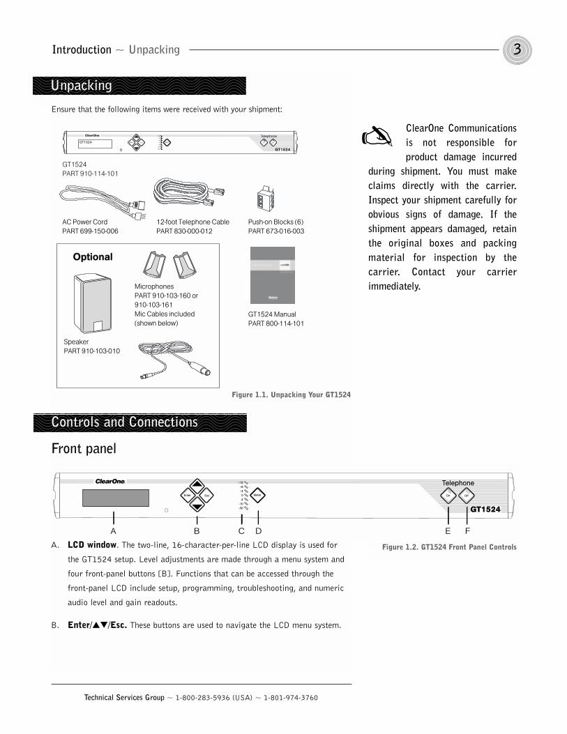
Ensure that the following items were received with your shipment:
Front panel
A. LCD window. The two-line, 16-character-per-line LCD display is used for
the GT1524 setup. Level adjustments are made through a menu system and
four front-panel buttons [B]. Functions that can be accessed through the
front-panel LCD include setup, programming, troubleshooting, and numeric
audio level and gain readouts.
B. Enter//Esc. These buttons are used to navigate the LCD menu system.
ClearOne Communicationsis not responsible forproduct damage incurred
during shipment. You must makeclaims directly with the carrier.Inspect your shipment carefully forobvious signs of damage. If theshipment appears damaged, retainthe original boxes and packingmaterial for inspection by thecarrier. Contact your carrierimmediately.
Unpacking
GT1524 ManualPART 800-114-101
GT1524PART 910-114-101
SpeakerPART 910-103-010
MicrophonesPART 910-103-160 or910-103-161Mic Cables included (shown below)
Meter
+12+8+4
0-4
-10-30
EscEnterGT1524 On Off
Telephone
AC Power CordPART 699-150-006
12-foot Telephone CablePART 830-000-012
Push-on Blocks (6)PART 673-016-003
Optional
Figure 1.1. Unpacking Your GT1524
Controls and Connections
Meter
+12+8+4
0-4
-10-30
EscEnter On Off
Telephone
A B C D E F
Figure 1.2. GT1524 Front Panel Controls
Introduction ~ Controls and Connections4
Technical Services Group ~ 1-800-283-5936 (USA) ~ 1-801-974-3760
C. LED Meter. The LED bar meter displays the audio level of any input or
output of the GT1524 as well as the Echo Return Loss (ERL) and Echo
Return Loss Enhancement (ERLE) between the Speaker/Line Out and the
Mic/Line audio input channel. The LED meter also displays Telco Echo
Return Loss (TERL) and Telco Echo Return Loss Enhancement (TERLE) for
the telephone hybrid.
D. Meter. This button displays the Meter branch of the GT1524’s LCD menu
tree from which you can view or enter settings.
E. On. The On button connects and adapts the GT1524 to the telephone line.
Pressing and holding the On button for more than two seconds while the
GT1524 is active sends a noise burst to readapt the unit to the phone line. A
short tone (1000Hz) is sent out the Speaker and Line outputs to indicate
that the GT1524 is connected to the line.
F. Off. The Off switch disconnects the GT1524 from the telephone line and
mutes all transmit audio to and from the telephone line. A short tone
(400Hz) is sent out the Speaker and Line Outputs to notify the user that the
GT1524 is disconnected from the line.
Rear panel
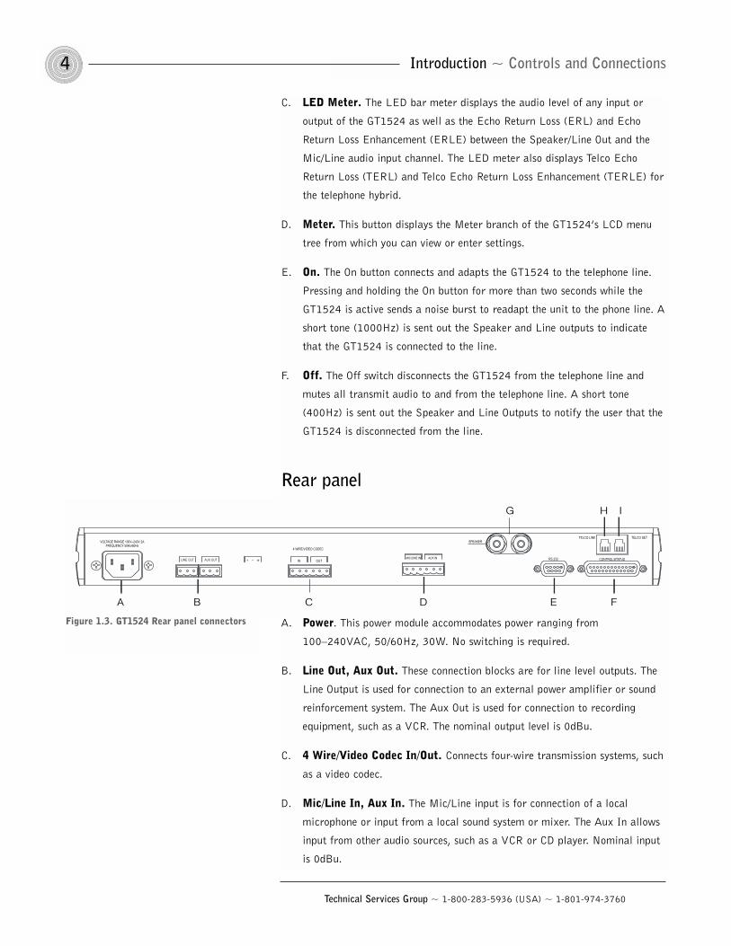
A. Power. This power module accommodates power ranging from
100–240VAC, 50/60Hz, 30W. No switching is required.
B. Line Out, Aux Out. These connection blocks are for line level outputs. The
Line Output is used for connection to an external power amplifier or sound
reinforcement system. The Aux Out is used for connection to recording
equipment, such as a VCR. The nominal output level is 0dBu.
C. 4 Wire/Video Codec In/Out. Connects four-wire transmission systems, such
as a video codec.
D. Mic/Line In, Aux In. The Mic/Line input is for connection of a local
microphone or input from a local sound system or mixer. The Aux In allows
input from other audio sources, such as a VCR or CD player. Nominal input
is 0dBu.
A B C D E F
G H I
Figure 1.3. GT1524 Rear panel connectors
5Introduction ~ Operational Requirements
Technical Services Group ~ 1-800-283-5936 (USA) ~ 1-801-974-3760
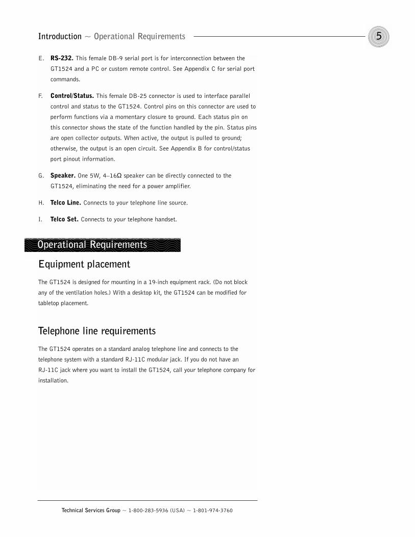
E. RS-232. This female DB-9 serial port is for interconnection between the
GT1524 and a PC or custom remote control. See Appendix C for serial port
commands.
F. Control/Status. This female DB-25 connector is used to interface parallel
control and status to the GT1524. Control pins on this connector are used to
perform functions via a momentary closure to ground. Each status pin on
this connector shows the state of the function handled by the pin. Status pins
are open collector outputs. When active, the output is pulled to ground;
otherwise, the output is an open circuit. See Appendix B for control/status
port pinout information.
G. Speaker. One 5W, 4–16Ω speaker can be directly connected to the
GT1524, eliminating the need for a power amplifier.
H. Telco Line. Connects to your telephone line source.
I. Telco Set. Connects to your telephone handset.
Equipment placement
The GT1524 is designed for mounting in a 19-inch equipment rack. (Do not block
any of the ventilation holes.) With a desktop kit, the GT1524 can be modified for
tabletop placement.
Telephone line requirements
The GT1524 operates on a standard analog telephone line and connects to the
telephone system with a standard RJ-11C modular jack. If you do not have an
RJ-11C jack where you want to install the GT1524, call your telephone company for
installation.
Operational Requirements

6
Technical Services Group ~ 1-800-283-5936 (USA) ~ 1-801-974-3760
Technical Services Group ~ 1-800-283-5936 (USA) ~ 1-801-974-3760
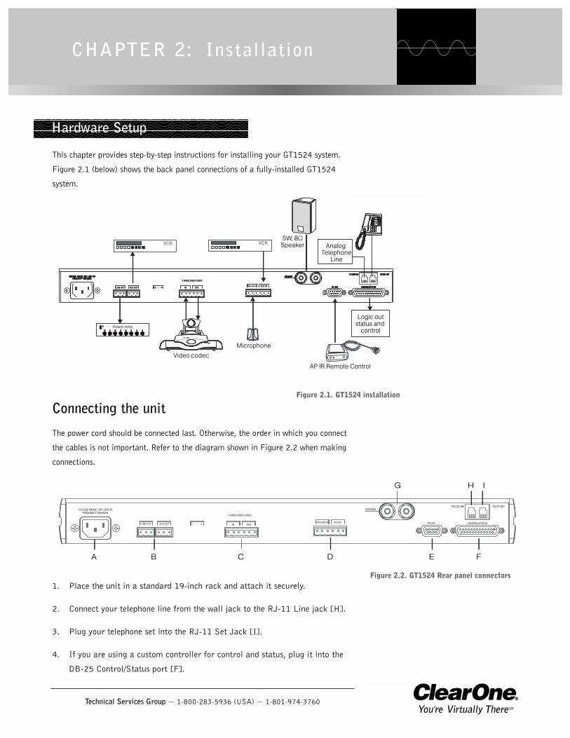
This chapter provides step-by-step instructions for installing your GT1524 system.
Figure 2.1 (below) shows the back panel connections of a fully-installed GT1524
system.
Connecting the unit
The power cord should be connected last. Otherwise, the order in which you connect
the cables is not important. Refer to the diagram shown in Figure 2.2 when making
connections.
1. Place the unit in a standard 19-inch rack and attach it securely.
2. Connect your telephone line from the wall jack to the RJ-11 Line jack [H].
3. Plug your telephone set into the RJ-11 Set Jack [I].
4. If you are using a custom controller for control and status, plug it into the
DB-25 Control/Status port [F].
CHAPTER 2: Installation
LINE OUT AUX OUT
4 WIRE/VIDEO CODEC
OUTIN AUX INMIC/LINE IN
Logic outstatus and
control
Analog Telephone
Line
5W, 8ΩSpeaker
Power Amp
Video codecMicrophone
MUTE IN USEREADY
AP IR Remote Control
Figure 2.1. GT1524 installation
Hardware Setup
A B C D E F
G H I
Figure 2.2. GT1524 Rear panel connectors
Installation ~ LCD Programming8
Technical Services Group ~ 1-800-283-5936 (USA) ~ 1-801-974-3760
5. Use the RS-232 port to connect the GT1524 to a PC (for use with
HyperTerminal), an AP IR Remote Control, or a custom remote control
device.
6. Connect an external amplifier or sound reinforcement system to Line Out.
Use Aux Out to connect recording equipment, such as a VCR. Nominal
output is 0dBu.
7. Using the included connectors, wire a 4-wire transmission system, such as a
video codec, to the 4 Wire/Video Codec In and Out connectors. Nominal
input/output is 0dBu.
8. Connect a local microphone or input from a local sound system or mixer to
Mic/Line In.
9. Connect the speaker wire to the + (red) and – (black) binding post
connectors.
10. Connect the power cable after making all other connections. As soon as
power is supplied to the unit, the GT1524 initializes and all front-panel
LEDs and the LCD light. The power module accommodates 100–240VAC,
50/60Hz, 22–30W.
For most installations, the default settings in the GT1524 do not need to be changed;
the system can be used as soon as power is applied. However, if you need to
customize any settings, such as telephone connection options or input parameters,
you can do so through the front panel user interface.
The front panel includes a 2x16 character LCD, menu buttons, and LED bar
meter. When power is applied to the GT1524, all LEDs light and the LCD panel
reads INITIALIZING. If initialization is completed without errors, a title screen
appears, showing the product name (top line) and the version number (bottom
line). The title screen remains on display until you initiate some action that writes
information to the LCD panel or the GT1524 detects and displays an error. If an
error is displayed, contact ClearOne Technical Support.
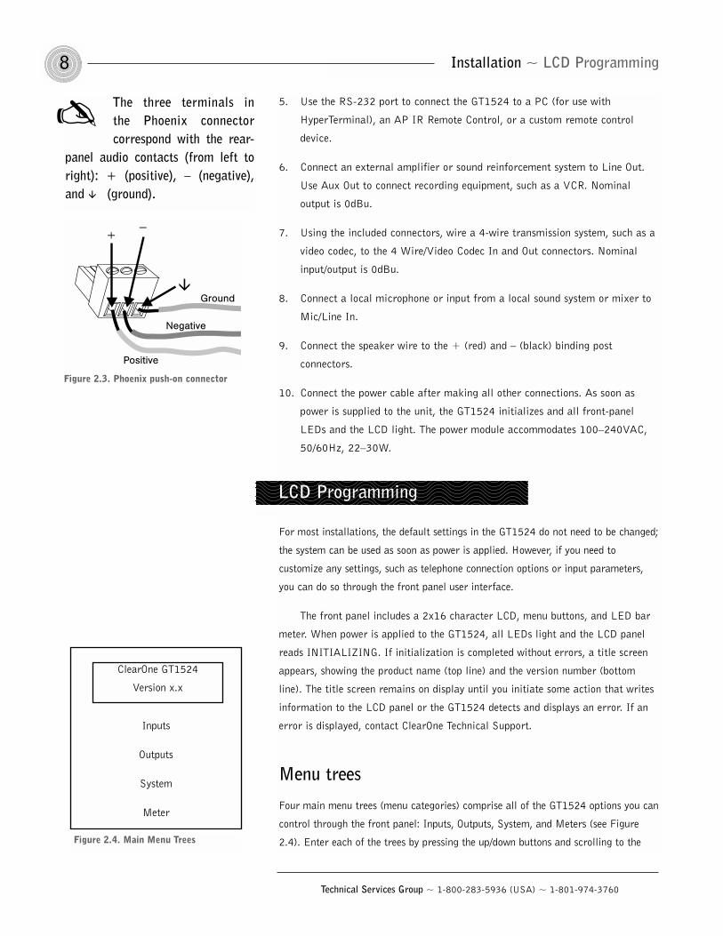
Menu trees
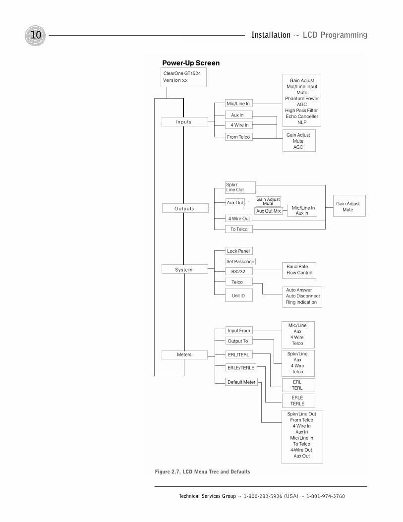
Four main menu trees (menu categories) comprise all of the GT1524 options you can
control through the front panel: Inputs, Outputs, System, and Meters (see Figure
2.4). Enter each of the trees by pressing the up/down buttons and scrolling to the
The three terminals in the Phoenix connectorcorrespond with the rear-
panel audio contacts (from left toright): + (positive), – (negative),and (ground).
Figure 2.3. Phoenix push-on connector
LCD Programming
Inputs
Outputs
System
Meter
Figure 2.4. Main Menu Trees
ClearOne GT1524
Version x.x
Pressing ESC at the top ofthe tree has no effect.
9Installation ~ LCD Programming
Technical Services Group ~ 1-800-283-5936 (USA) ~ 1-801-974-3760
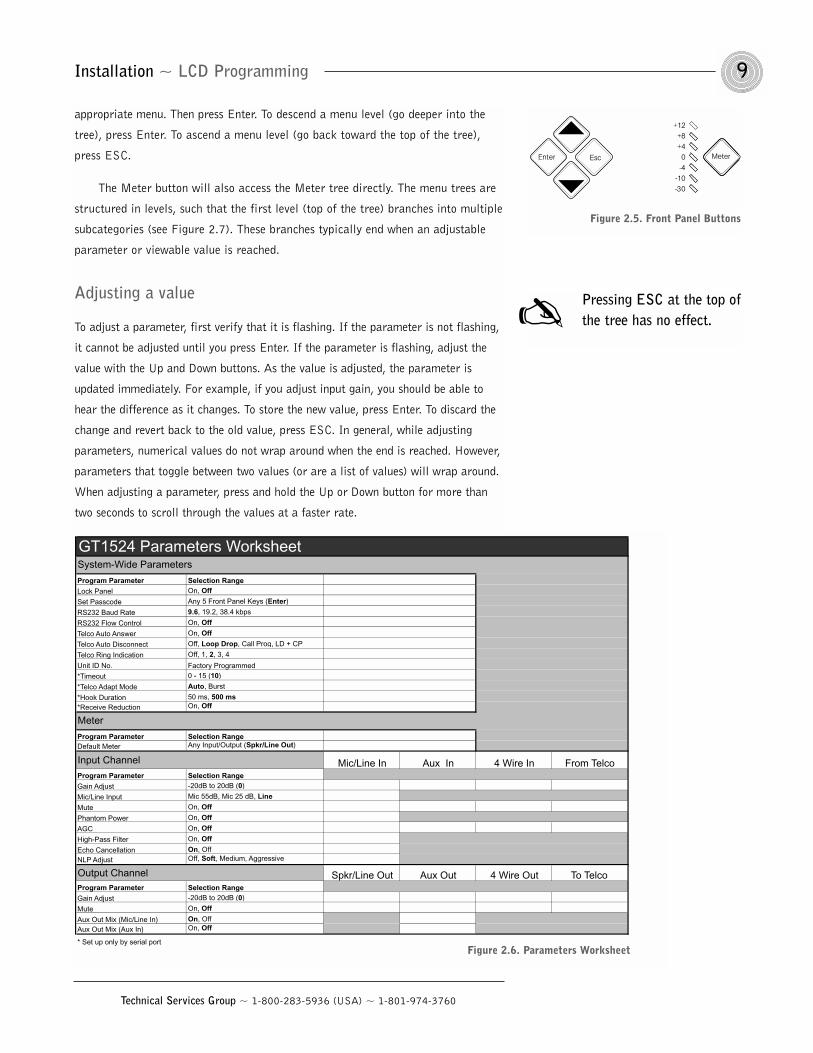
appropriate menu. Then press Enter. To descend a menu level (go deeper into the
tree), press Enter. To ascend a menu level (go back toward the top of the tree),
press ESC.
The Meter button will also access the Meter tree directly. The menu trees are
structured in levels, such that the first level (top of the tree) branches into multiple
subcategories (see Figure 2.7). These branches typically end when an adjustable
parameter or viewable value is reached.
Adjusting a value
To adjust a parameter, first verify that it is flashing. If the parameter is not flashing,
it cannot be adjusted until you press Enter. If the parameter is flashing, adjust the
value with the Up and Down buttons. As the value is adjusted, the parameter is
updated immediately. For example, if you adjust input gain, you should be able to
hear the difference as it changes. To store the new value, press Enter. To discard the
change and revert back to the old value, press ESC. In general, while adjusting
parameters, numerical values do not wrap around when the end is reached. However,
parameters that toggle between two values (or are a list of values) will wrap around.
When adjusting a parameter, press and hold the Up or Down button for more than
two seconds to scroll through the values at a faster rate.
Meter
+12+8+4
0-4
-10-30
EscEnter
Figure 2.5. Front Panel Buttons
GT1524 Parameters Worksheet
Program Parameter Selection RangeLock Panel On, Off
Set Passcode Any 5 Front Panel Keys (Enter)
RS232 Baud Rate 9.6, 19.2, 38.4 kbps
RS232 Flow Control On, Off
Telco Auto Answer On, Off
Telco Auto Disconnect Off, Loop Drop, Call Prog, LD + CP
Telco Ring Indication Off, 1, 2, 3, 4
Unit ID No. Factory Programmed
*Timeout 0 - 15 (10)
*Telco Adapt Mode Auto, Burst
*Hook Duration 50 ms, 500 ms*Receive Reduction On, Off
Program Parameter Selection RangeDefault Meter Any Input/Output (Spkr/Line Out)
Mic/Line In Aux In 4 Wire In From TelcoProgram Parameter Selection RangeGain Adjust -20dB to 20dB (0)
Mic/Line Input Mic 55dB, Mic 25 dB, Line
Mute On, Off
Phantom Power On, Off
AGC On, Off
High-Pass Filter On, Off
Echo Cancellation On, OffNLP Adjust Off, Soft, Medium, Aggressive
Spkr/Line Out Aux Out 4 Wire Out To TelcoProgram Parameter Selection RangeGain Adjust -20dB to 20dB (0)
Mute On, Off
Aux Out Mix (Mic/Line In) On, OffAux Out Mix (Aux In) On, Off
* Set up only by serial port
Output Channel
System-Wide Parameters
Input Channel
Meter
Figure 2.6. Parameters Worksheet
Installation ~ LCD Programming10
Technical Services Group ~ 1-800-283-5936 (USA) ~ 1-801-974-3760
Ve rsio n x.x
O u tp u ts
In p u ts
S yste m
ClearOne GT1524
Mic/Line In
Aux In
From Telco
4 Wire In
Spkr/ Line Out
To Telco
4 Wire Out
Lock Panel
Set Passcode
Telco
RS232
Output To
ERL/TERL
ERLE/TERLE
Gain AdjustMic/Line Input
MutePhantom Power
AGCHigh Pass Filter Echo Canceller
NLP
Gain AdjustMuteAGC
Power-Up Screen
Gain AdjustMute
Unit ID
Baud RateFlow Control
Auto AnswerAuto Disconnect
Input FromMic/Line
Aux4 Wire Telco
Spkr/LineAux
4 WireTelco
ERLTERL
Ring Indication
Spkr/Line OutFrom Telco
4 Wire InAux In
Mic/Line InTo Telco
4-Wire Out Aux Out
Mic/Line InAux In
Gain AdjustMuteAux Out
Default Meter
ERLETERLE
Meters
Aux Out Mix
Figure 2.7. LCD Menu Tree and Defaults
11Installation ~ LCD Programming
Technical Services Group ~ 1-800-283-5936 (USA) ~ 1-801-974-3760
Inputs
There are four main submenus under the Inputs menu tree: Mic/Line In, Aux In, 4
Wire In, and From Telco (see Figure 2.7).
Mic/Line In
Gain Adjust. This adjusts the Mic/Line In submenus, including the level for the
Input gain (ranging between -20dB and 20dB). The default setting is 0dB.
Mic/Line Input. This input defaults as a line-level input (0dB gain) but can be
switched to a mic level input (55dB or 25dB gain).
Mute. This parameter mutes the input channel.
Phantom Power. Defaults with 24V phantom power disabled, but may be switched
on to accommodate input devices requiring phantom power.
AGC. The input can use automatic gain control (AGC). This feature keeps softer and
louder talkers at a consistent transmit level. This feature is disabled when shipped
from the factory. The target gain is 0dB and adjusts at 2dB per second. The AGC
start adjustment is -20dB, but will adjust only +6dB. Adjustments will not be made
at .5dB on either side of the target (0dB).
High-Pass Filter. A high-pass filter may be selected on the Mic/Line input to
reduce unwanted noise. The filter has a break frequency at 250Hz, and -3dB down
at 200Hz, then rolls off at 6dB per octave. This feature is disabled when shipped
from the factory.
Echo Canceller. Activate or deactivate the echo cancellation feature for this input.
Factory default is On.
NLP Adjust. Non-linear processing (NLP) has four settings: soft (6dB), medium
(12dB), aggressive (18dB), and Off. NLP adds more echo cancelling “horsepower”
in difficult acoustical environments. Use care when increasing NLP, because of the
corresponding trade-offs which can include suppression and half-duplex operation.
Factory default is Soft.
Aux In, 4-Wire In, and From Telco
Gain Adjust. This adjusts each Input gain (ranging between -20dB and 20dB) in
conjunction with the LCD readout and the LED bar graph. The default setting is
0dBu.
Mute. This parameter mutes the input channel.
Installation ~ LCD Programming12
Technical Services Group ~ 1-800-283-5936 (USA) ~ 1-801-974-3760
AGC. The input can use automatic gain control (AGC). This feature keeps softer and
louder talkers at a consistent transmit level. This feature is disabled when shipped
from the factory. The target gain is 0dB and adjusts at 2dB per second. The AGC
start adjustment is -20dB, but will adjust only +6dB. Adjustments will not be made
at .5dB on either side of the target (0dB).
Outputs
There are four main submenu under the Outputs menu tree: Speaker/Line Out, Aux
Out, 4 Wire Out, and To Telco. Each of these submenus contain the same menus at
the next menu depth: Gain Adjust and Mute. Aux Out also features an Aux Out Mix
parameter, described below. Each parameter is applied to the respective outputs.
Speaker/Line Out, 4 Wire Out, and To Telco
Gain Adjust. This adjusts each output’s gain (ranging between -20dB and 20dB), in
conjunction with the LCD readout and the LED bar meter. Default is 0dB.
Mute. This parameter mutes a particular output channel. Default is Off.
Aux Out
Gain Adjust. This adjusts each output’s gain (ranging between -20dB and 20dB), in
conjunction with the LCD readout and the LED bar meter. Default is 0dB.
Mute. This parameter mutes a particular output channel. Default is OFF.
Aux Out Mix. This parameter selects Mic/Line In and/or Aux In to Aux Out.
System
The System menu allows you to view five parameters: Lock Panel, Set Passcode,
RS-232, Telco, and Unit ID. The first four may also be adjusted.
Lock Panel
The GT1524 can be secured from unauthorized adjustments by locking the front
panel and establishing a user passcode. Menu items can still be viewed when the
panel is locked, but settings cannot be altered or entered until the panel is unlocked
by entering the appropriate passcode.
If you enter a passcodeand unlock the system, youmust lock it again after
making any changes. Otherwise thepanel will remain unlocked andaccessible to anyone.
13Installation ~ LCD Programming
Technical Services Group ~ 1-800-283-5936 (USA) ~ 1-801-974-3760
To lock the front panel
1. Enter the System menu
2. Scroll through the menu items to select Lock Panel, and press Enter.
3. Select On, and press Enter again.
To unlock the front panel
1. Attempt to adjust a parameter. The GT1524 prompts you for the passcode.
2. Begin entering the passcode. Once you have correctly entered the fifth
character, the front panel unlocks. (The default passcode for all units is Up,
Up, Down, Down, Enter.)
Set Passcode
Once you have unlocked the GT1524, you can change the passcode. Before the
GT1524 allows passcode changes, the new passcode must be entered, then re-entered
to validate it. The passcode must be five front panel buttons (in any combination or
multiple).
RS-232
Two RS-232 parameters can be adjusted through the front panel LCD: baud rate and
flow control. If data is lost during serial access through the RS-232 port, a serial
overrun error will occur. This is indicated on the LCD display. This parameter sets
the GT1524’s RS-232 port communication rate at 9,600 (default), 19,200, or
38,400 baud (bps).
Baud. To set the baud rate, scroll through the settings to select the desired baud
rate, then press Enter.
Flow Control. The flow control parameter allows activation and deactivation of
hardware flow control. The two options are On and Off (default). To activate the flow
control, scroll to On and press Enter. To deactivate it, scroll to Off and press Enter.
Telco
Auto-Answer On/Off. This parameter sets the telephone interface to automatically
answer an incoming call (Auto-Answer On), or allow the call to be handled manually
(Auto-Answer Off).
Auto-Disconnect. The interface can also be set to disconnect upon Loop Drop, Call
Progress, Loop Drop + CP, or to disconnect manually (Auto-Disconnect Off).
Installation ~ LCD Programming14
Technical Services Group ~ 1-800-283-5936 (USA) ~ 1-801-974-3760
Ring Indication. An audible ring indicator, sent to the PA output, can be enabled
or disabled under this menu.
Unit ID Number
The Unit ID # allows you to view the read-only unit address set at the factory. This
unique ID number identifies that particular unit and cannot be changed.
Meters
There are five main submenus under the meter menu tree: Inputs, Outputs,
ERL/TERL, ERLE/TERLE, and Default Meter. The first four submenus are all
handled in the same way.
Inputs, Outputs, ERL/TERL, and ERLE/TERLE
Referencing the LCD, press the Meter button, then scroll through the options (Inputs,
Outputs, ERL/TERL and ERLE/TERLE) to specify which is to be metered by the
front-panel LED meter. When the appropriate option is visible, press Enter to begin
monitoring its status on the front panel LCD. All items under this menu can be
scrolled through by pressing the / arrows.
Default Meter
The default meter parameter determines what is being displayed on the LED meter
when the GT1524 times out.
Timeout
The GT1524 has a system mode called Timeout. This parameter can be adjusted
through the RS-232 port only using the TOUT command. Timeout controls the delay
time (in minutes) before the LCD panel will automatically switch back to the title
screen and default meter. The range is 0–15 minutes. Default is 10 minutes; 0
disables this mode.
Disabling the timeout willallow the GT1524 toremain in the same
position in the LCD menu until theLCD menu is manipulated again.
Technical Services Group ~ 1-800-283-5936 (USA) ~ 1-801-974-3760
A correctly installed GT1524 virtually runs by itself. Typical operations involve
changing volume of an output, muting an input or output, or handling calls on the
connected telephone handset. For most installations, a custom remote control
(optional) is also used.
Controlling volume
When participating in a conference, you might find it necessary to increase or
decrease the volume of a particular output. For instance, when the audio at a distant
location is too soft, adjust the output to the speakers so that the level is comfortable.
To adjust the volume
1. Determine which output needs to be adjusted.
2. Scroll to the Outputs menu, select the appropriate output, and scroll to
Gain Adjust. Press Enter.
3. Adjust the gain level using the / buttons. You should be able to hear the
volume level adjust while increasing or decreasing the gain.
4. Press Enter when you reach the desired volume level.
The volume adjust procedure is the same for all channels.
Muting
To mute and unmute
1. Select the input or output you want to mute and press Enter.
3. Scroll through the parameters until you see Mute. Press Enter.
4. Use the / buttons to select On, then press Enter. The input or output is
now muted. To unmute, follow the same procedure, but select Off to
deactivate the mute function.
CHAPTER 3: Operation
For optimum performance,adjust all inputs to 0dBubefore calibrating outputs.
Front Panel Control
Operation ~ Front Panel Control16
Technical Services Group ~ 1-800-283-5936 (USA) ~ 1-801-974-3760
Answering a call
An incoming call rings on the telephone set connected to the GT1524 (and speaker, if
one is connected to the GT1524) and causes the On LED to flash. There are four
ways to answer an incoming call:
To answer a call
You can answer a call using any of the following methods:
• Press the On button on either the front panel or on the remote control. This
will route the call through the GT1524.
• Pick up the telephone handset and talk to your party over the telephone.
Press the front panel On button to connect the call to the GT1524.
• Use external control such as an AMX or Crestron touch panel or custom
control device. See page 21 for information on using serial commands.
Making a call
Call the party using your handset. After the other party has answered, route the call
through the GT1524 by pressing the On button.
The On LED lights and the GT1524 takes control of the call, disabling the
telephone set. You can now safely hang up the handset without disconnecting the
call or access the DTMF dialer in the GT1524 via a remote control system.
Disconnecting a call
If the call is routed through the GT1524 (the On LED glows green), press the Off
button on the front panel or send a command through the RS-232 port (TE 0). The
Off LED glows red, and the On LED turns off.
If Auto-Answer is turnedOn under System settings,the GT1524 answers the
call after the second complete ring.A ringing tone is provided to theLine and Speaker output if RingIndication is turned on.
When using the DIALserial port command, theGT1524 automatically
engages the hybrid. You do not needto press the On button.
If Auto-Disconnect isturned On in Systemsettings, the GT1524
disconnects upon sensing loop dropor call progress tones.
17Operation ~ Custom Control
Technical Services Group ~ 1-800-283-5936 (USA) ~ 1-801-974-3760
Custom controller options
The GT1524 is designed to function with remote control systems. The controller is
connected to the GT1524 through the RS-232 port. The AP IR Remote also
functions with the GT1524.
You can perform all actions through the custom controller:
• Turn the GT1524 telephone connection on or off
• Mute transmitted and received audio
• Generate DTMF tones
• Adjust volume on received audio
• Re-null the telephone hybrid
• Meter input and output
• Read TERL and TERLE
• Control any function on the unit
ClearOne Communicationsrecommends use of acustom remote controller
for user interface. Refer to themanufacturer’s documentation foryour particular custom remotecontroller.
Custom Control

18
Technical Services Group ~ 1-800-283-5936 (USA) ~ 1-801-974-3760
Technical Services Group ~ 1-800-283-5936 (USA) ~ 1-801-974-3760
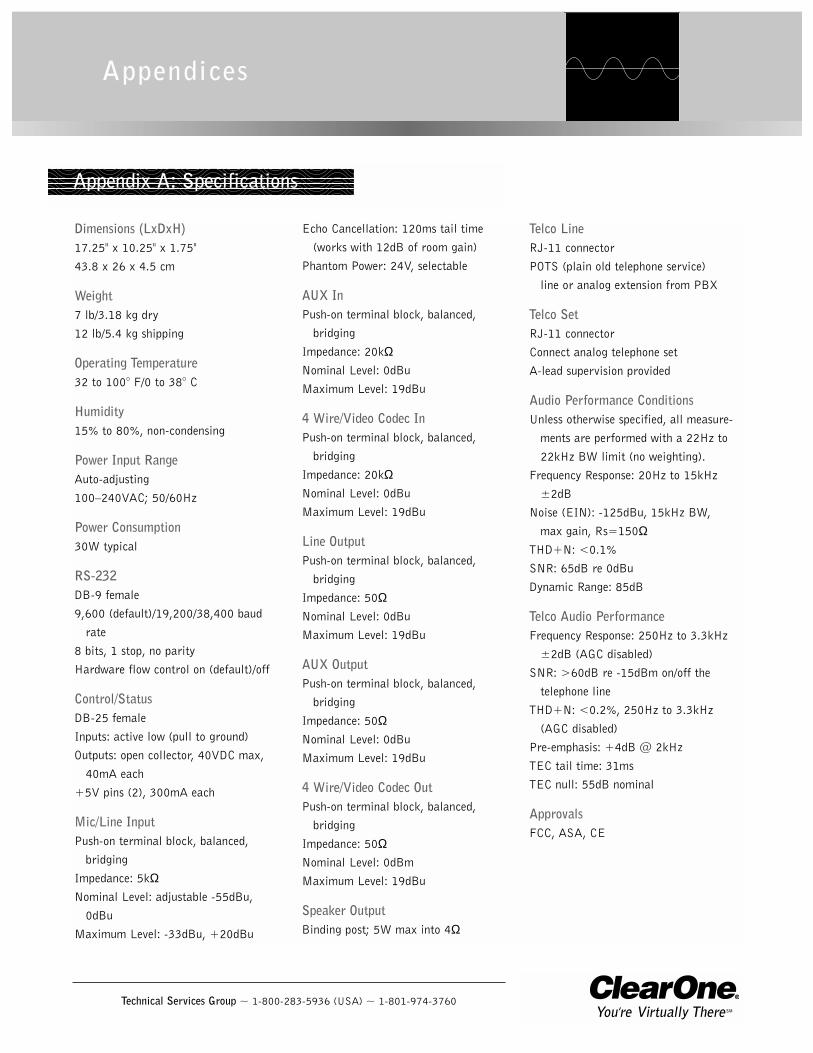
Dimensions (LxDxH)17.25" x 10.25" x 1.75"
43.8 x 26 x 4.5 cm
Weight7 lb/3.18 kg dry
12 lb/5.4 kg shipping
Operating Temperature32 to 100° F/0 to 38° C
Humidity15% to 80%, non-condensing
Power Input RangeAuto-adjusting
100–240VAC; 50/60Hz
Power Consumption30W typical
RS-232DB-9 female
9,600 (default)/19,200/38,400 baud
rate
8 bits, 1 stop, no parity
Hardware flow control on (default)/off
Control/StatusDB-25 female
Inputs: active low (pull to ground)
Outputs: open collector, 40VDC max,
40mA each
+5V pins (2), 300mA each
Mic/Line InputPush-on terminal block, balanced,
bridging
Impedance: 5kΩNominal Level: adjustable -55dBu,
0dBu
Maximum Level: -33dBu, +20dBu
Echo Cancellation: 120ms tail time
(works with 12dB of room gain)
Phantom Power: 24V, selectable
AUX InPush-on terminal block, balanced,
bridging
Impedance: 20kΩNominal Level: 0dBu
Maximum Level: 19dBu
4 Wire/Video Codec InPush-on terminal block, balanced,
bridging
Impedance: 20kΩNominal Level: 0dBu
Maximum Level: 19dBu
Line OutputPush-on terminal block, balanced,
bridging
Impedance: 50ΩNominal Level: 0dBu
Maximum Level: 19dBu
AUX OutputPush-on terminal block, balanced,
bridging
Impedance: 50ΩNominal Level: 0dBu
Maximum Level: 19dBu
4 Wire/Video Codec OutPush-on terminal block, balanced,
bridging
Impedance: 50ΩNominal Level: 0dBm
Maximum Level: 19dBu
Speaker OutputBinding post; 5W max into 4Ω
Telco LineRJ-11 connector
POTS (plain old telephone service)
line or analog extension from PBX
Telco SetRJ-11 connector
Connect analog telephone set
A-lead supervision provided
Audio Performance ConditionsUnless otherwise specified, all measure-
ments are performed with a 22Hz to
22kHz BW limit (no weighting).
Frequency Response: 20Hz to 15kHz
±2dB
Noise (EIN): -125dBu, 15kHz BW,
max gain, Rs=150ΩTHD+N: <0.1%
SNR: 65dB re 0dBu
Dynamic Range: 85dB
Telco Audio PerformanceFrequency Response: 250Hz to 3.3kHz
±2dB (AGC disabled)
SNR: >60dB re -15dBm on/off the
telephone line
THD+N: <0.2%, 250Hz to 3.3kHz
(AGC disabled)
Pre-emphasis: +4dB @ 2kHz
TEC tail time: 31ms
TEC null: 55dB nominal
ApprovalsFCC, ASA, CE
Appendices
Appendix A: Specifications
Appendix B ~ Pinouts20
Technical Services Group ~ 1-800-283-5936 (USA) ~ 1-801-974-3760
All commands aremomentary.
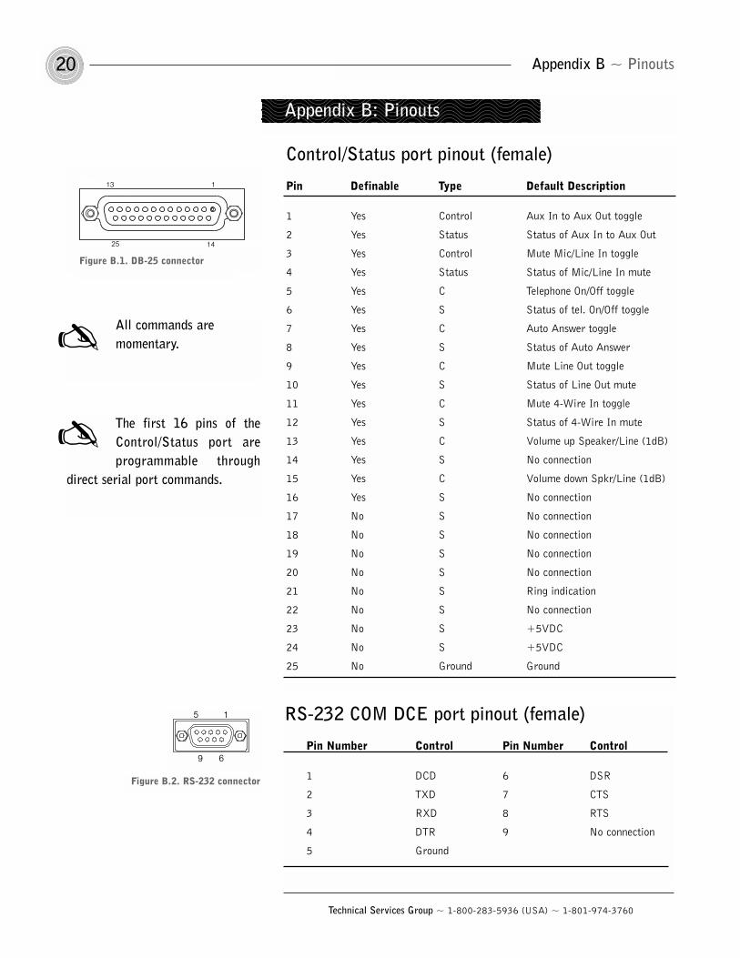
Appendix B: Pinouts
RS-232 COM DCE port pinout (female)
Pin Number Control Pin Number Control
1 DCD 6 DSR
2 TXD 7 CTS
3 RXD 8 RTS
4 DTR 9 No connection
5 Ground
15
69
Figure B.2. RS-232 connector
Control/Status port pinout (female)
Pin Definable Type Default Description
1 Yes Control Aux In to Aux Out toggle
2 Yes Status Status of Aux In to Aux Out
3 Yes Control Mute Mic/Line In toggle
4 Yes Status Status of Mic/Line In mute
5 Yes C Telephone On/Off toggle
6 Yes S Status of tel. On/Off toggle
7 Yes C Auto Answer toggle
8 Yes S Status of Auto Answer
9 Yes C Mute Line Out toggle
10 Yes S Status of Line Out mute
11 Yes C Mute 4-Wire In toggle
12 Yes S Status of 4-Wire In mute
13 Yes C Volume up Speaker/Line (1dB)
14 Yes S No connection
15 Yes C Volume down Spkr/Line (1dB)
16 Yes S No connection
17 No S No connection
18 No S No connection
19 No S No connection
20 No S No connection
21 No S Ring indication
22 No S No connection
23 No S +5VDC
24 No S +5VDC
25 No Ground Ground
13
25
1
14
Figure B.1. DB-25 connector
The first 16 pins of theControl/Status port areprogrammable through
direct serial port commands.
21Appendix C ~ Serial Commands
Technical Services Group ~ 1-800-283-5936 (USA) ~ 1-801-974-3760
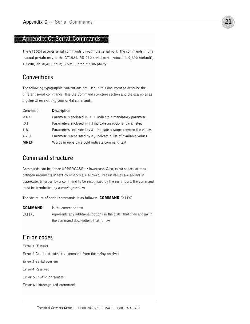
The GT1524 accepts serial commands through the serial port. The commands in this
manual pertain only to the GT1524. RS-232 serial port protocol is 9,600 (default),
19,200, or 38,400 baud; 8 bits, 1 stop bit, no parity.
Conventions
The following typographic conventions are used in this document to describe the
different serial commands. Use the Command structure section and the examples as
a guide when creating your serial commands.
Convention Description<X> Parameters enclosed in < > indicate a mandatory parameter.
[X] Parameters enclosed in [ ] indicate an optional parameter.
1-8 Parameters separated by a - indicate a range between the values.
4,7,9 Parameters separated by a , indicate a list of available values.
MREF Words in uppercase bold indicate command text.
Command structure
Commands can be either UPPERCASE or lowercase. Also, extra spaces or tabs
between arguments in text commands are allowed. Return values are always in
uppercase. In order for a command to be recognized by the serial port, the command
must be terminated by a carriage return.
The structure of serial commands is as follows: COMMAND [X] [X]
COMMAND is the command text
[X] [X] represents any additional options in the order that they appear in
the command descriptions that follow
Error codesError 1 (Future)
Error 2 Could not extract a command from the string received
Error 3 Serial overrun
Error 4 Reserved
Error 5 Invalid parameter
Error 6 Unrecognized command
Appendix C: Serial Commands
Appendix C ~ Serial Commands22
Technical Services Group ~ 1-800-283-5936 (USA) ~ 1-801-974-3760
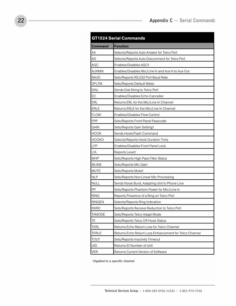
GT1524 Serial Commands
Command Function
AA Selects/Reports Auto Answer for Telco Port
AD Selects/Reports Auto Disconnnect for Telco Port
AGC Enables/Disables AGC†
AUXMIX Enables/Disables Mic/Line In and Aux In to Aux Out
BAUD Sets/Reports RS-232 Port Baud Rate
DFLTM Sets/Reports Default Meter
DIAL Sends Dial String to Telco Port
EC Enables/Disables Echo Canceller
ERL Returns ERL for the Mic/Line In Channel
ERLE Returns ERLE for the Mic/Line In Channel
FLOW Enables/Disables Flow Control
FPP Sets/Reports Front Panel Passcode
GAIN Sets/Reports Gain Setting†
HOOK Sends Hook/Flash Command
HOOKD Selects/Reports Hook Duration Time
LFP Enables/Disables Front Panel Lock
LVL Reports Level†
MHP Sets/Reports High Pass Filter Status
MLINE Sets/Reports Mic Gain
MUTE Sets/Reports Mute†
NLP Sets/Reports Non-Linear Mic Processing
NULL Sends Noise Burst, Adapting Unit to Phone Line
PP Sets/Reports Phantom Power for Mic/Line In
RING Reports Presence of a Ring on Telco Port
RINGEN Selects/Reports Ring Indication
RXRD Sets/Reports Receive Reduction to Telco Port
TAMODE Sets/Reports Telco Adapt Mode
TE Sets/Reports Telco Off Hook Status
TERL Returns Echo Return Loss for Telco Channel
TERLE Returns Echo Return Loss Enhancement for Telco Channel
TOUT Sets/Reports Inactivity Timeout
UID Returns ID Number of Unit
VER Returns Current Version of Software
†Applied to a specific channel
23Appendix C ~ Serial Commands
Technical Services Group ~ 1-800-283-5936 (USA) ~ 1-801-974-3760
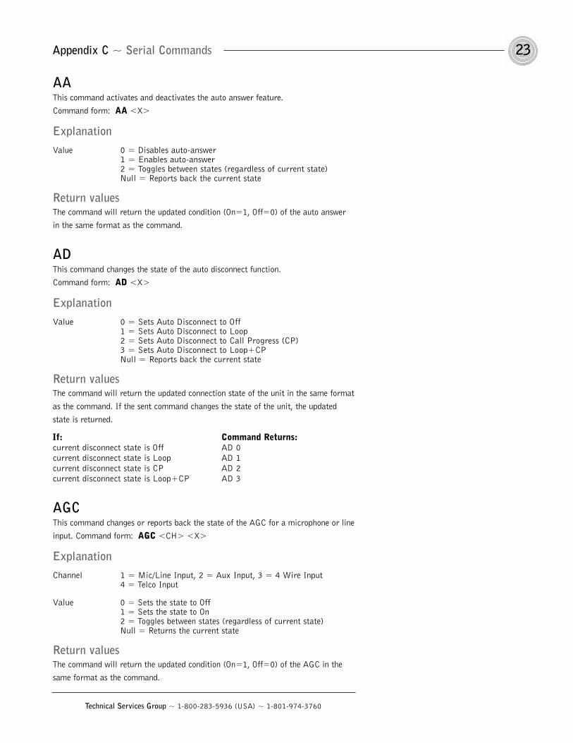
AAThis command activates and deactivates the auto answer feature.
Command form: AA <X>
ExplanationValue 0 = Disables auto-answer
1 = Enables auto-answer2 = Toggles between states (regardless of current state)Null = Reports back the current state
Return valuesThe command will return the updated condition (On=1, Off=0) of the auto answer
in the same format as the command.
ADThis command changes the state of the auto disconnect function.
Command form: AD <X>
ExplanationValue 0 = Sets Auto Disconnect to Off
1 = Sets Auto Disconnect to Loop2 = Sets Auto Disconnect to Call Progress (CP)3 = Sets Auto Disconnect to Loop+CPNull = Reports back the current state
Return valuesThe command will return the updated connection state of the unit in the same format
as the command. If the sent command changes the state of the unit, the updated
state is returned.
If: Command Returns:current disconnect state is Off AD 0
current disconnect state is Loop AD 1
current disconnect state is CP AD 2
current disconnect state is Loop+CP AD 3
AGCThis command changes or reports back the state of the AGC for a microphone or line
input. Command form: AGC <CH> <X>
ExplanationChannel 1 = Mic/Line Input, 2 = Aux Input, 3 = 4 Wire Input
4 = Telco Input
Value 0 = Sets the state to Off1 = Sets the state to On2 = Toggles between states (regardless of current state)Null = Returns the current state
Return valuesThe command will return the updated condition (On=1, Off=0) of the AGC in the
same format as the command.
Appendix C ~ Serial Commands24
Technical Services Group ~ 1-800-283-5936 (USA) ~ 1-801-974-3760
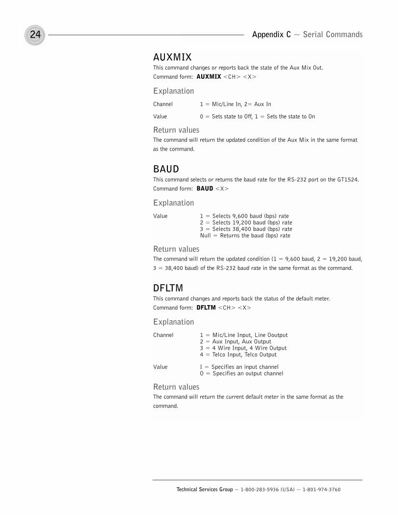
AUXMIXThis command changes or reports back the state of the Aux Mix Out.
Command form: AUXMIX <CH> <X>
ExplanationChannel 1 = Mic/Line In, 2= Aux In
Value 0 = Sets state to Off, 1 = Sets the state to On
Return valuesThe command will return the updated condition of the Aux Mix in the same format
as the command.
BAUDThis command selects or returns the baud rate for the RS-232 port on the GT1524.
Command form: BAUD <X>
ExplanationValue 1 = Selects 9,600 baud (bps) rate
2 = Selects 19,200 baud (bps) rate3 = Selects 38,400 baud (bps) rateNull = Returns the baud (bps) rate
Return valuesThe command will return the updated condition (1 = 9,600 baud, 2 = 19,200 baud,
3 = 38,400 baud) of the RS-232 baud rate in the same format as the command.
DFLTMThis command changes and reports back the status of the default meter.
Command form: DFLTM <CH> <X>
ExplanationChannel 1 = Mic/Line Input, Line Ooutput
2 = Aux Input, Aux Output3 = 4 Wire Input, 4 Wire Output4 = Telco Input, Telco Output
Value I = Specifies an input channelO = Specifies an output channel
Return valuesThe command will return the current default meter in the same format as the
command.
25Appendix C ~ Serial Commands
Technical Services Group ~ 1-800-283-5936 (USA) ~ 1-801-974-3760
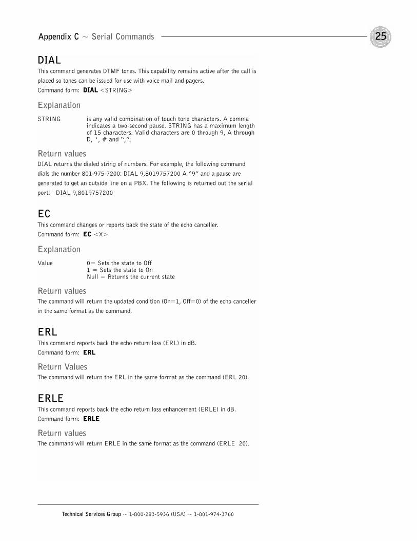
DIALThis command generates DTMF tones. This capability remains active after the call is
placed so tones can be issued for use with voice mail and pagers.
Command form: DIAL <STRING>
ExplanationSTRING is any valid combination of touch tone characters. A comma
indicates a two-second pause. STRING has a maximum length of 15 characters. Valid characters are 0 through 9, A through D, *, # and “,”.
Return valuesDIAL returns the dialed string of numbers. For example, the following command
dials the number 801-975-7200: DIAL 9,8019757200 A “9” and a pause are
generated to get an outside line on a PBX. The following is returned out the serial
port: DIAL 9,8019757200
ECThis command changes or reports back the state of the echo canceller.
Command form: EC <X>
ExplanationValue 0= Sets the state to Off
1 = Sets the state to OnNull = Returns the current state
Return valuesThe command will return the updated condition (On=1, Off=0) of the echo canceller
in the same format as the command.
ERLThis command reports back the echo return loss (ERL) in dB.
Command form: ERL
Return ValuesThe command will return the ERL in the same format as the command (ERL 20).
ERLEThis command reports back the echo return loss enhancement (ERLE) in dB.
Command form: ERLE
Return valuesThe command will return ERLE in the same format as the command (ERLE 20).
Appendix C ~ Serial Commands26
Technical Services Group ~ 1-800-283-5936 (USA) ~ 1-801-974-3760
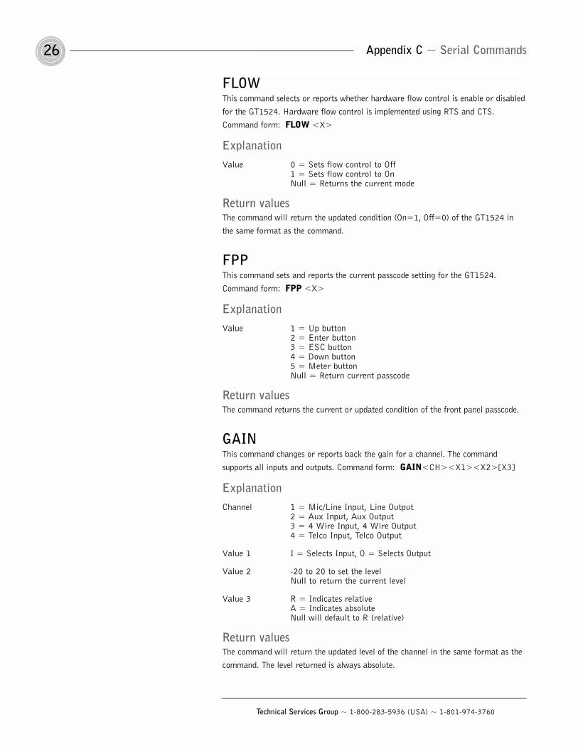
FLOWThis command selects or reports whether hardware flow control is enable or disabled
for the GT1524. Hardware flow control is implemented using RTS and CTS.
Command form: FLOW <X>
ExplanationValue 0 = Sets flow control to Off
1 = Sets flow control to OnNull = Returns the current mode
Return valuesThe command will return the updated condition (On=1, Off=0) of the GT1524 in
the same format as the command.
FPPThis command sets and reports the current passcode setting for the GT1524.
Command form: FPP <X>
ExplanationValue 1 = Up button
2 = Enter button3 = ESC button4 = Down button5 = Meter buttonNull = Return current passcode
Return valuesThe command returns the current or updated condition of the front panel passcode.
GAINThis command changes or reports back the gain for a channel. The command
supports all inputs and outputs. Command form: GAIN<CH><X1><X2>[X3]
ExplanationChannel 1 = Mic/Line Input, Line Output
2 = Aux Input, Aux Output3 = 4 Wire Input, 4 Wire Output4 = Telco Input, Telco Output
Value 1 I = Selects Input, O = Selects Output
Value 2 -20 to 20 to set the levelNull to return the current level
Value 3 R = Indicates relativeA = Indicates absoluteNull will default to R (relative)
Return valuesThe command will return the updated level of the channel in the same format as the
command. The level returned is always absolute.
27Appendix C ~ Serial Commands
Technical Services Group ~ 1-800-283-5936 (USA) ~ 1-801-974-3760
ExampleThe following command lowers the gain 3dB on the Mic/Line input channel.
GAIN 1 I -3
HOOKThis command sends a momentary interruption in the line seizure (hook flash) to the
telephone line. Command form: HOOK
Return valuesIf hook flash succeeded, the following is returned out the port: HOOK 0
HOOKDThis command controls and reports the Hook Duration of the unit.
Command form: HOOKD <X>
ExplanationValues 1 = Sets Hook Duration to 50 ms
2 = Sets Hook Duration to 500 msNull = Reports back the current state
Return valuesThe command will return the current hook duration of the unit in the same format as
the command. If the sent command changes the hook duration of the unit, the
updated hook duration is returned.
LFPThis command locks, unlocks, or returns the current state of the front panel from the
serial port. Command form: LFP <X>
ExplanationValues 0 = Unlocks the front panel
1 = Locks the front panel2 = Toggles between states (regardless of current state)Null = Returns the current state of the front panel
Return valuesThe command will return the updated condition of the front panel.
Appendix C ~ Serial Commands28
Technical Services Group ~ 1-800-283-5936 (USA) ~ 1-801-974-3760
LVLThis command reports back the level for a given channel.
Command form: LVL <CH> <X>
ExplanationChannel 1 = Mic/Line Input, Line Output
2 = Aux Input, Aux Output3 = 4 Wire Input, 4 Wire Output 4 = Telco Input, Telco Output
Value I = Specifies an input meterO = Specifies an output meter
Return valuesThe command will return the input level of the channel in the same format as the
command.
MHPThis command changes or reports back the state of the high pass filter for the
Mic/Line input. Command form: MHP <X>
ExplanationValue 0 = Sets the state to Off
1 = Set the state to OnNull = Returns the current state
Return valuesThe command will return the updated condition (On=1, Off=0) of the high pass
filter in the same format as the command.
MLINEThis command changes or reports back how much gain is applied to the Mic/Line
input. The three settings are 0dB, 25dB, and 55dB.
Command form: MLINE <X>
ExplanationValue 1 = Sets the state to 55dB gain
2 = Sets the state to 25dB gain3 = Sets the state to 0dB (line level)Null = Returns the current state
Return valuesThe command will return the updated condition of the gain applied in the same
format as the command.
29Appendix C ~ Serial Commands
Technical Services Group ~ 1-800-283-5936 (USA) ~ 1-801-974-3760
MUTEThis command changes or reports the state of mute for a given channel.
Command form: MUTE <CH> <X1> <X2>
ExplanationChannel 1 = Mic/Line Input, Line Output
2 = Aux Input, Aux Output3 = 4 Wire Input, 4 Wire Output4 = Telco Input, Telco Output
Value 1 I = Specifies inputO = Specifies output
Value 2 0 = Sets mute to Off1 = Sets mute to On (mute the selected channel)2 = Toggles between states (regardless of current state)Null = Reports current mute state for the selected channel
Return valuesThe command will return the mute status (On=1, Off=0) in the same format as the
command.
NLPThis command changes or reports back the state of the nonlinear processing for the
echo canceller. Command form: NLP <X>
ExplanationValue 0 = Sets the state to Off
1 = Sets the state to soft2 = Sets the state to medium3 = Sets the state to aggressiveNull = Returns the current state
Return valuesThe command will return the updated condition (0=Off, 1=Soft, 2=Medium,
3=Aggressive) of the nonlinear processing in the same format as the command.
NULLThis command sends a short noise burst down the telephone line and adapts the
GT1524 to the telephone line. Command form: NULL
Return valuesNULL is returned out the serial port when the command has been executed.
Appendix C ~ Serial Commands30
Technical Services Group ~ 1-800-283-5936 (USA) ~ 1-801-974-3760
PPThis command changes or reports back the state of the phantom power for a
microphone. Command form: PP <X>
ExplanationValue 0 = Sets the state to Off
1 = Sets the state to OnNull = Returns the current state
Return valuesThe command will return the updated condition (On=1, Off=0) of the phantom
power in the same format as the command.
RINGThis command reports the presence of a Ring on the Telco port. (This is an indication
only.) Command form: RING
Return valueThe Ring is sent if a valid ring has been sensed on the Telco line: RING
RINGENThis command changes or reports back the state of the Ring Indication.
Command form: RINGEN <X>
ExplanationValue 0 = Sets the state to Off
1 = Sets the state to Ring 12 = Sets the state to Ring 23 = Sets the state to Ring 34 = Sets the state to Ring 4Null = Returns the current state
Return valuesThe command will return the updated condition of the Ring Indication in the same
format as the command.
RXRDThis command controls or reports the Receive Reduction control of the unit.
Command form: RXRD <X>
ExplanationValues 0 = Sets Receive Reduction to Off
1 = Sets Receive Reduction to On2 = Toggles the current stateNull = Reports back the current state
Return valuesThe command returns the updated connection state of the unit in the same format as
the command.
31Appendix C ~ Serial Commands
Technical Services Group ~ 1-800-283-5936 (USA) ~ 1-801-974-3760
TAMODEThis command controls or reports the Telephone Adapt Mode control of the unit.
Command form: TAMODE <X>
ExplanationValue 0 = Sets Telephone Adapt Mode to Auto
1 = Sets Telephone Adapt Mode to BurstNull = Reports back the current state
Return valueThe command returns the updated connection state of the unit in the same format as
the command.
TEThis command controls or reports the connection status of the unit.
Command form: TE <X>
ExplanationValues 0 = Sets the unit to disconnect from the line
1 = Sets the unit to connect to the line2 = Toggles the statesNull = Reports back the current state
Return valueIf the current state is On, the following is returned: TE 1. If the current state is Off,
the following is returned out the serial port: TE 0
TERL
This command reports back the telephone echo return loss (TERL) for the GT1524
in decibels. Command form: TERL
ExampleIf the current TERL level is 10dB, the following is returned out the serial port:
TERL 10
TERLEThis command reports back the telephone echo return loss enhancement (TERLE)
for the GT1524 in decibels. Command form: TERLE
ExampleIf the current TERLE level for the telephone canceller is 20dB, the following is
returned out the serial port: TERLE 20
Appendix C ~ Serial Commands32
Technical Services Group ~ 1-800-283-5936 (USA) ~ 1-801-974-3760
TOUTThis command sets or reports the current inactivity timeout before returning to the
menu screen used by the unit. Command form: TOUT <X>
ExplanationValue 0 = Disables inactivity timeout
1–15 = Sets the number of minutes specifiedNull = Returns the current number of minutes
Return ValuesThe command will return the current timeout value. If the command changed the
timeout, the updated timeout is returned.
UIDThis command returns the unique ID number, the device type, and the device number
of the GT1524. This command is read only. The unique ID number is
preprogrammed at the factory and is unique to the unit. Command form: UID
Return ValuesUID returns the device type and unique ID number. The unique ID is composed of an
eight-digit hex number assigned at the factory to uniquely identify the unit.
ExampleThe following command requests the unit ID from device: UID
The following is returned out the serial port: UID A4EF906C
VERThis command returns the current version of software. This version is unique to a
released version of software and is comprised of the DSP, the FPGA, and HC11
software. This command is read only. VER
Return ValuesVER returns the version of software in the same format as the command. The
Version is composed of a major version number followed by a period and a minor
version number.
ExampleThe following command requests the software version: The following is returned out
the serial port: VER 2.0
33Appendix D ~ Warranty
Technical Services Group ~ 1-800-283-5936 (USA) ~ 1-801-974-3760
ClearOne Communications, Inc. (Manufacturer) warrants that this product is
free of defects in both materials and workmanship. Should any part of this
product be defective, the Manufacturer agrees, at its option, to:
A. Repair or replace any defective part free of charge (except transportation
charges) for a period of one year from the date of installation for the end-
user, provided the owner returns the product to the Manufacturer at the
address set forth below. No charge will be made for parts or labor during
this period;
B. Furnish replacement for any defective parts in the product for a period of
one year from the date of original purchase. Replacement parts shall be
furnished without charge, except labor and transportation.
This Warranty excludes assembled products not manufactured by the
Manufacturer whether or not they are incorporated in a Manufacturer product or
sold under a Manufacturer part or model number.
THIS WARRANTY IS VOID IF:
A. The product has been damaged by negligence, accident, act of God, or
mishandling, or has not been operated in accordance with the procedures
described in the operating and technical instructions; or,
B. The product has been altered or repaired by other than the Manufacturer or
an authorized service representative of the Manufacturer; or,
C. Adaptations or accessories other than those manufactured or provided by the
Manufacturer have been made or attached to the product which, in the
determination of the Manufacturer, shall have affected the performance,
safety or reliability of the product; or,
D. The product’s original serial number has been modified or removed.
NO OTHER WARRANTY, EXPRESS OR IMPLIED, INCLUDING WARRANTIES
OF MERCHANTABILITY OR FITNESS FOR ANY PARTICULAR USE, APPLIES
TO THE PRODUCT. MANUFACTURER’S MAXIMUM LIABILITY HEREUNDER
SHALL BE THE AMOUNT PAID BY THE END-USER FOR THE PRODUCT. No
person or entity authorized to assume any obligation or other liability in connection
with the products. No action, regardless of form, arising out of or relating to the
product or this Warranty, may be brought by end-user more than one (1) year after
the cause of action has accrued.
Warranty
Appendix E ~ Compliance34
Technical Services Group ~ 1-800-283-5936 (USA) ~ 1-801-974-3760
Manufacturer shall not be liable for punitive, consequential, or incidental
damages, expenses, or loss of revenue or property, inconvenience, or interruption
in operation experienced by the end user due to a malfunction in the purchased
product. No warranty service performed on any product shall extend the
applicable warranty period.
In case of unsatisfactory operation, the end-user shall promptly notify the
Manufacturer at the address set forth below in writing, giving full particulars as to
the defects or unsatisfactory operation. Upon receipt of such notice, the
Manufacturer will give instructions respecting the shipment of the product, or such
other matters as it elects to honor this warranty as above provided. This warranty
does not cover damage to the product during shipping and the Manufacturer
assumes no responsibility for such damage. All shipping costs shall be paid by the
customer.
This warranty extends only to the original end user and is not assignable or
transferable. This Warranty is governed by the laws of the State of Utah, without
regard to the conflicts of interests provisions thereof.
ClearOne Communications
1825 Research Way
Salt Lake City, Utah 84119
FCC Part 15 compliance
This device complies with part 15 of the FCC rules. Operation is subject to the
following two conditions: (1) This device may not cause harmful interference, and (2)
this device must accept any interference received, including interference that may
cause undesired operation.
FCC Part 68 compliance
A label containing, among other information, the FCC registration number and
Ringer Equivalence Number (REN) for this equipment is prominently posted on the
equipment. If requested, this information must be provided to your telephone
company.
Appendix E: Compliance
35Appendix E ~ Compliance
Technical Services Group ~ 1-800-283-5936 (USA) ~ 1-801-974-3760
USOC Jacks: This device uses RJ11C and RJ21X terminal jacks.
The REN is used to determine the quantity of devices which may be connected
to the telephone line. Excessive RENs on the telephone line may result in the
devices not ringing in response to an incoming call. In most, but not all areas, the
sum of the RENs should not exceed five (5). To be certain of the number of devices
that may be connected to the line, as determined by the total RENs, contact the
telephone company to obtain the maximum RENs for the calling area.
If this equipment causes harm to the telephone network, the telephone
company will notify you in advance that temporary discontinuance of service may
be required. If advance notice is not practical, the telephone company will notify
the customer as soon as possible. Also, you will be advised of your right to file a
complaint with the FCC if you believe it is necessary. The telephone company may
make changes in its facilities, equipment, operations, or procedures that could
affect the operation of the equipment. If this happens, the telephone company will
provide advance notice for you to make the necessary modifications in order to
maintain uninterrupted service.
If you experience problems with this equipment, contact ClearOne
Communications, Inc., 1825 Research Way, Salt Lake City, Utah 84119, or by
phone at (801) 874-3760 for repair and warranty information. If the trouble is
causing harm to the telephone network, the telephone company may request you
remove the equipment from the network until the problem is resolved.
Industry Canada compliance
The Industry of Canada label identifies certified equipment. This certification means
that the equipment meets certain telecommunications network protective operational
and safety requirements. The Department does not guarantee the equipment will
operate to the user’s satisfaction.
Before installing this equipment, users should ensure that it is permissible to
be connected to the facilities of the local telecommunications company. The
equipment must also be installed using an acceptable method of connection. In
some cases, the company’s inside wiring associated with a single line individual
service may be extended by means of a certified connector assembly (telephone
extension cord). The customer should be aware that compliance with the above
conditions may not prevent degradation of service in some situations.
Repairs to certified equipment should be made by an authorized Canadian
maintenance facility designated by ClearOne Communications. Any repairs or
alterations made by the user to this equipment, or equipment malfunctions, may
Appendix E ~ Compliance36
Technical Services Group ~ 1-800-283-5936 (USA) ~ 1-801-974-3760
give the telecommunications company cause to request the user to disconnect the
equipment.
Users should ensure for their own protection that the electrical ground
connections of the power utility, telephone lines and internal metallic water pipe
system, if present, are connected together. This precaution may be particularly
important in rural areas.
European compliance (for international unit part
no. 910-114-102 only)
This equipment has been approved in accordance with Council Decision 98/482/EC
for pan-European single terminal connection to the public switched telephone
network (PSTN). However, due to differences between the individual PSTNs
provided in different countries, the approval does not, of itself, give an unconditional
assurance of successful operation on every PSTN network termination point.
In the event of problems, you should contact your equipment supplier in the
first instance.
ClearOne Communications, Inc. of 1825 Research Way, Salt Lake City, Utah
84119, U.S.A. declares that this equipment is designed to be compatible with the
following networks: Austria, Belgium, Denmark, Finland, France, Germany,
Greece, Iceland, Ireland, Italy, Liechtenstein, Luxembourg, The Netherlands,
Norway, Portugal, Spain, Sweden, Switzerland, and United Kingdom
The international unit, part no. 910-114-102, complies with the
requirements of the European guidelines:
89/336/EEC “Electromagnetic Compatibility”
73/23/EEC “Electrical operating material for use within specific voltage
limits”
98/482/EC “Single terminal connection to the public switched telephone
network.”
Conformity of the equipment with the above guidelines is attested by the CE mark.
37Index ~ A–R
Technical Services Group ~ 1-800-283-5936 (USA) ~ 1-801-974-3760
4 Wire In 4, 8, 19
4 Wire Out 4, 8, 12, 19
Aacoustic echo cancellation 1
AGC 11, 12
answering a call 16
AP IR Remote 8
auto-answer 13, 16
auto-disconnect 13, 16
Aux In 4, 11, 19
Aux Out 4, 8, 12, 19
Aux Out Mix 12
Bbaud 13
Ccall progress 13
control/status 5, 7, 19, 20
DDB-25 5, 20
default meter 14
digital signal processors 1
disconnecting a call 16
Eecho cancellation 19
echo canceller 11
ERL 4, 14
ERLE 4, 14
Fflow control 13
frequency response 19
from telco 11
front-panel LEDs 8
Ggain adjust 11, 12, 15
Hhigh-pass filter 11
Iinputs 14
installation 7
LLCD display 3, 8
LCD panel 14
LCD programming 8
Line Out 4, 8, 19
Lock panel 12, 13
loop drop 13
loop drop + CP 13
Mmaking a call 16
Meters 4, 14
Mic/Line In 4, 8, 11, 19
mute 11, 12, 15
NNLP adjust 11
noise 19
noise burst 4
Ooutputs 12, 14
Ppasscode 12
phantom power 11
pinouts 20
power 4, 8
product registration 2
product returns 2
Rring indication 14, 16
RS-232 5, 8, 12, 13, 19
Index
Index ~ S–Z38
Technical Services Group ~ 1-800-283-5936 (USA) ~ 1-801-974-3760
Sserial commands 21
set passcode 12, 13
speaker 5, 8
Speaker/Line Out 12, 19
system 12, 13
Ttechnical support 2
telco 12, 13, 19
telco echo cancellation 1
Telco Line 5, 19
Telco Set 5, 19
telephone handset 16
TERL 4, 14
TERLE 4, 14
timeout 14
To Telco 12
touch-tone dialing 1
two-wire/four-wire operation 1
UUnit ID 12, 14
unmute 15
Vvideo codec 8
Video Codec In 4, 8, 19
Video Codec Out 4, 8, 19
volume control 15