gas-fired, gravity-vented unit heaters - gogeisel.com b... · gas-fired, gravity-vented unit...
TRANSCRIPT
Form RGM 434, Mfg No. 98126 Rev 8, Page 1
INSTALLATION FORM RGM 434 (Version A)Obsoletes 434-8
APPLIES TO: Installation/Operation/Service
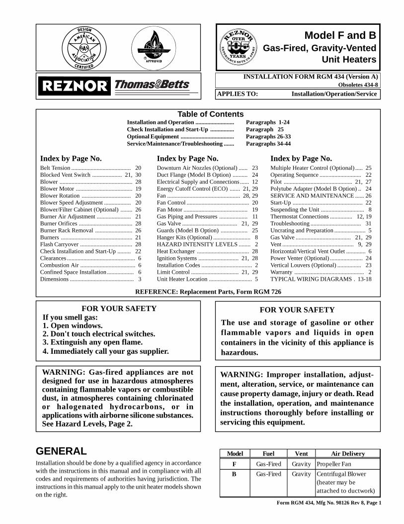
Model F and BGas-Fired, Gravity-Vented
Unit Heaters
GENERALInstallation should be done by a qualified agency in accordancewith the instructions in this manual and in compliance with allcodes and requirements of authorities having jurisdiction. Theinstructions in this manual apply to the unit heater models shownon the right.
FOR YOUR SAFETY
The use and storage of gasoline or otherflammable vapors and liquids in opencontainers in the vicinity of this appliance ishazardous.
WARNING: Gas-fired appliances are notdesigned for use in hazardous atmospherescontaining flammable vapors or combustibledust, in atmospheres containing chlorinatedor halogenated hydrocarbons, or inapplications with airborne silicone substances.See Hazard Levels, Page 2.
WARNING: Improper installation, adjust-ment, alteration, service, or maintenance cancause property damage, injury or death. Readthe installation, operation, and maintenanceinstructions thoroughly before installing orservicing this equipment.
FOR YOUR SAFETYIf you smell gas:1. Open windows.2. Don't touch electrical switches.3. Extinguish any open flame.4. Immediately call your gas supplier.
Index by Page No.Belt Tension ........................................ 20Blocked Vent Switch .................... 21, 30Blower ................................................. 28Blower Motor ...................................... 19Blower Rotation ................................. 20Blower Speed Adjustment .................. 20Blower/Filter Cabinet (Optional) ........ 26Burner Air Adjustment ....................... 21Burner Orifices .................................... 28Burner Rack Removal ......................... 26Burners ................................................ 21Flash Carryover ................................... 28Check Installation and Start-Up ......... 22Clearances .............................................. 6Combustion Air ..................................... 6Confined Space Installation .................. 6Dimensions ........................................... 3
Index by Page No.Downturn Air Nozzles (Optional) ...... 23Duct Flange (Model B Option) .......... 24Electrical Supply and Connections ...... 12Energy Cutoff Control (ECO) ....... 21, 29Fan ................................................. 28, 29Fan Control .......................................... 20Fan Motor ........................................... 19Gas Piping and Pressures ................... 11Gas Valve ..................................... 21, 29Guards (Model B Option) .................. 25Hanger Kits (Optional) ......................... 8HAZARD INTENSITY LEVELS ........ 2Heat Exchanger ................................... 28Ignition Systems ........................... 21, 28Installation Codes .................................. 2Limit Control ................................ 21, 29Unit Heater Location ............................. 5
Index by Page No.Multiple Heater Control (Optional) ..... 25Operating Sequence ............................ 22Pilot .............................................. 21, 27Polytube Adapter (Model B Option) .. 24SERVICE AND MAINTENANCE ...... 26Start-Up ............................................... 22Suspending the Unit ............................. 8Thermostat Connections ............... 12, 19Troubleshooting .................................. 31Uncrating and Preparation ..................... 5Gas Valve ..................................... 21, 29Vent ................................................ 9, 29Horizontal/Vertical Vent Outlet ............. 6Power Venter (Optional) ...................... 24Vertical Louvers (Optional) ................ 23Warranty ............................................... 2TYPICAL WIRING DIAGRAMS . 13-18
Table of ContentsInstallation and Operation .......................... Paragraphs 1-24Check Installation and Start-Up ................ Paragraph 25Optional Equipment .................................... Paragraphs 26-33Service/Maintenance/Troubleshooting ....... Paragraphs 34-44
Model Fuel Vent Air Delivery
F Gas-Fired Gravity Propeller Fan
B Gas-Fired Gravity Centrifugal Blower (heater may be attached to ductwork)
REFERENCE: Replacement Parts, Form RGM 726
Form RGM 434, Mfg No. 98126 Rev 8, Page 2
1. Installation CodesThe gas-fired unit heaters covered in this manual are design-certifiedby the American Gas Association and approved by the Canadian GasAssociation for use with either natural or propane gas. The type of gasfor which your heater is equipped and the correct firing rate are shownon the rating plate attached to your unit. Electrical characteristics areshown on the motor nameplate and on the unit rating plate.
These units must be installed in accordance with local building codes.In the absence of local codes, in the United States, the unit must beinstalled in accordance with the National Fuel Gas Code (latest edi-tion). A Canadian installation must be in accordance with the CAN/CGA B149.1 and B149.2 Installation Code for Gas Burning Appli-ances and Equipment. These codes are available from CSA Informa-tion Services, 1-800-463-6727. Local authorities having jurisdictionshould be consulted before installation is made to verify local codesand installation procedure requirements.
Clearances from the heater and vent to combustible construction ormaterial in storage must conform with the National Fuel Gas CodeANSI Z223.1a (latest edition) pertaining to gas-burning devices, andsuch material must not attain a temperature over 160oF by continuedoperation of the heater.
Special Installations (Aircraft Hangars/Garages)Installations in aircraft hangars should be in accordance with ANSI/NFPA No. 409 (latest edition), Standard for Aircraft Hangars; in pub-lic garages in accordance with ANSI/NFPA No. 88A (latest edition),Standard for Parking Structures; and for repair garages in accordancewith ANSI/NFPA No. 88B (latest edition), Standard for Repair Ga-rages. ANSI/NFPA-88 (latest edition) specifies overhead heaters mustbe installed at least eight feet above the floor. In Canada, installationsin aircraft hangars should be in accordance with the requirements ofthe enforcing authorities, and in public garages in accordance with CAN/CGA B149 codes.
ANSI/NFPA 409 (latest edition) specifies a clearance of ten feet to thebottom of the heater from the highest surface of the top of the wing orengine enclosure of whatever aircraft would be the highest to be housedin the hangar, and a minimum clearance of eight feet from the floor inother sections of aircraft hangars, such as the offices, and shops whichcommunicate with areas used for servicing or storage. The heaters mustbe located so as to be protected from damage by aircraft or other ob-jects such as cranes and movable scaffolding. In addition, the heatersmust be located so as to be accessible for servicing, adjustment, etc.
2. WarrantyRefer to limited warranty information on the warranty card in the"Owner's Envelope".
WARRANTY: Warranty is void if......a. Unit Heaters are used in atmospheres containing flammable
vapors or atmospheres containing chlorinated or halogenatedhydrocarbons or airborne silicone substances.
b. Wiring is not in accordance with the diagram furnished with
the heater.c. Unit is installed without proper clearances to combustible ma-
terials or located in a confined space without proper ventila-
tion and air for combustion. (See Paragraphs 6 and 7.)d. Fan-type unit heater is connected to a duct system.
HAZARD INTENSITY LEVELS
1. DANGER: Failure to comply will result in severe personal injury or death and/or property damage.
2. WARNING: Failure to comply could result in severe personal injury or death and/or property damage.
3. CAUTION: Failure to comply could result in minor personal injury and/or property damage.
Form RGM 434, Mfg No. 98126 Rev 8, Page 3
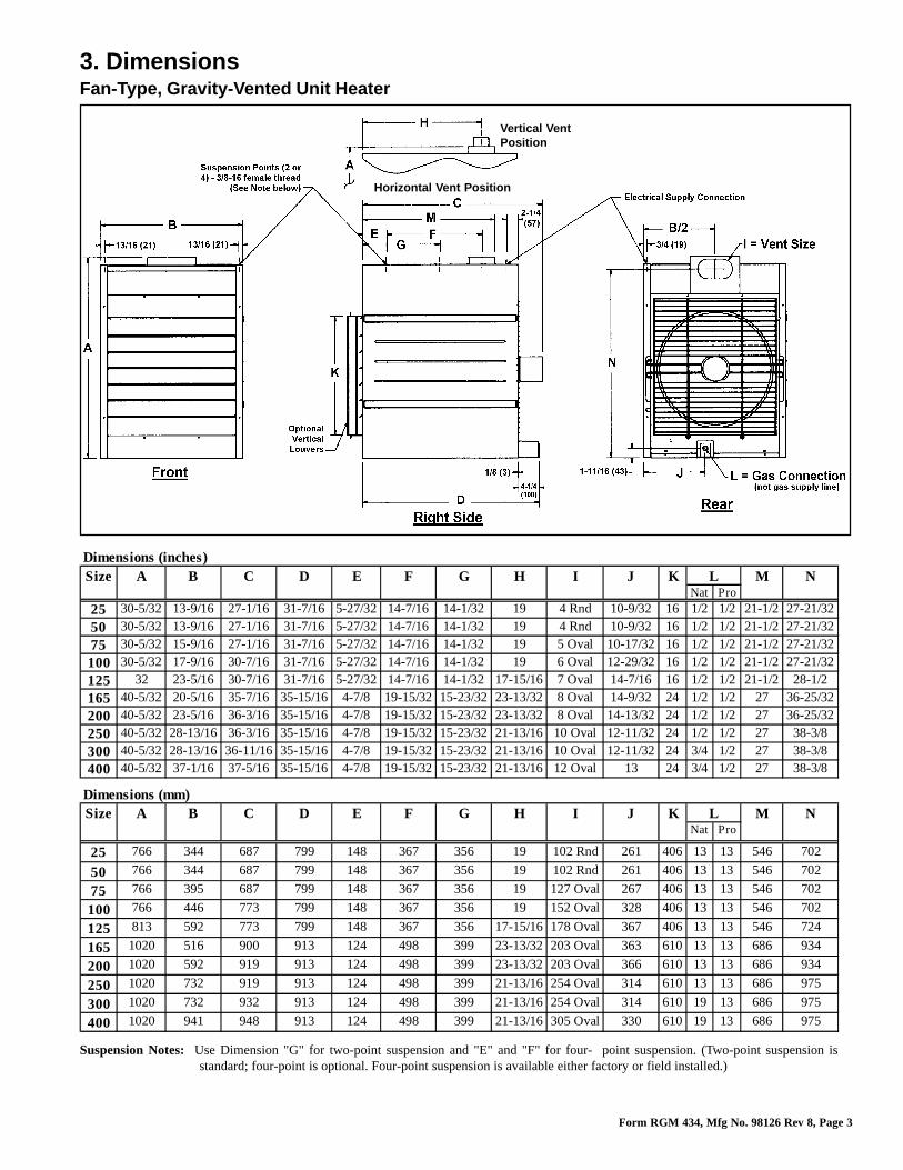
3. DimensionsFan-Type, Gravity-Vented Unit Heater
Suspension Notes: Use Dimension "G" for two-point suspension and "E" and "F" for four- point suspension. (Two-point suspension isstandard; four-point is optional. Four-point suspension is available either factory or field installed.)
Horizontal Vent Position
Vertical VentPosition
Dimensions (inches)Size A B C D E F G H I J K L M N
Nat Pro
25 30-5/32 13-9/16 27-1/16 31-7/16 5-27/32 14-7/16 14-1/32 19 4 Rnd 10-9/32 16 1/2 1/2 21-1/2 27-21/32
50 30-5/32 13-9/16 27-1/16 31-7/16 5-27/32 14-7/16 14-1/32 19 4 Rnd 10-9/32 16 1/2 1/2 21-1/2 27-21/32
75 30-5/32 15-9/16 27-1/16 31-7/16 5-27/32 14-7/16 14-1/32 19 5 Oval 10-17/32 16 1/2 1/2 21-1/2 27-21/32
100 30-5/32 17-9/16 30-7/16 31-7/16 5-27/32 14-7/16 14-1/32 19 6 Oval 12-29/32 16 1/2 1/2 21-1/2 27-21/32
125 32 23-5/16 30-7/16 31-7/16 5-27/32 14-7/16 14-1/32 17-15/16 7 Oval 14-7/16 16 1/2 1/2 21-1/2 28-1/2
165 40-5/32 20-5/16 35-7/16 35-15/16 4-7/8 19-15/32 15-23/32 23-13/32 8 Oval 14-9/32 24 1/2 1/2 27 36-25/32
200 40-5/32 23-5/16 36-3/16 35-15/16 4-7/8 19-15/32 15-23/32 23-13/32 8 Oval 14-13/32 24 1/2 1/2 27 36-25/32
250 40-5/32 28-13/16 36-3/16 35-15/16 4-7/8 19-15/32 15-23/32 21-13/16 10 Oval 12-11/32 24 1/2 1/2 27 38-3/8
300 40-5/32 28-13/16 36-11/16 35-15/16 4-7/8 19-15/32 15-23/32 21-13/16 10 Oval 12-11/32 24 3/4 1/2 27 38-3/8
400 40-5/32 37-1/16 37-5/16 35-15/16 4-7/8 19-15/32 15-23/32 21-13/16 12 Oval 13 24 3/4 1/2 27 38-3/8
Dimensions (mm)Size A B C D E F G H I J K L M N
Nat Pro
25 766 344 687 799 148 367 356 19 102 Rnd 261 406 13 13 546 702
50 766 344 687 799 148 367 356 19 102 Rnd 261 406 13 13 546 702
75 766 395 687 799 148 367 356 19 127 Oval 267 406 13 13 546 702
100 766 446 773 799 148 367 356 19 152 Oval 328 406 13 13 546 702
125 813 592 773 799 148 367 356 17-15/16 178 Oval 367 406 13 13 546 724
165 1020 516 900 913 124 498 399 23-13/32 203 Oval 363 610 13 13 686 934
200 1020 592 919 913 124 498 399 23-13/32 203 Oval 366 610 13 13 686 934
250 1020 732 919 913 124 498 399 21-13/16 254 Oval 314 610 13 13 686 975
300 1020 732 932 913 124 498 399 21-13/16 254 Oval 314 610 19 13 686 975
400 1020 941 948 913 124 498 399 21-13/16 305 Oval 330 610 19 13 686 975
Form RGM 434, Mfg No. 98126 Rev 8, Page 4
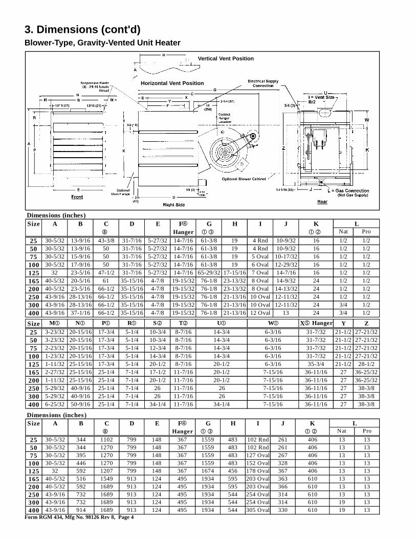
3. Dimensions (cont'd)Blower-Type, Gravity-Vented Unit Heater
Horizontal Vent Position
Vertical Vent Position
Dimensions (inches)Size A B C D E F� G H I J K L
� Hanger �� �� Nat Pro
25 30-5/32 13-9/16 43-3/8 31-7/16 5-27/32 14-7/16 61-3/8 19 4 Rnd 10-9/32 16 1/2 1/2
50 30-5/32 13-9/16 50 31-7/16 5-27/32 14-7/16 61-3/8 19 4 Rnd 10-9/32 16 1/2 1/2
75 30-5/32 15-9/16 50 31-7/16 5-27/32 14-7/16 61-3/8 19 5 Oval 10-17/32 16 1/2 1/2
100 30-5/32 17-9/16 50 31-7/16 5-27/32 14-7/16 61-3/8 19 6 Oval 12-29/32 16 1/2 1/2
125 32 23-5/16 47-1/2 31-7/16 5-27/32 14-7/16 65-29/32 17-15/16 7 Oval 14-7/16 16 1/2 1/2
165 40-5/32 20-5/16 61 35-15/16 4-7/8 19-15/32 76-1/8 23-13/32 8 Oval 14-9/32 24 1/2 1/2
200 40-5/32 23-5/16 66-1/2 35-15/16 4-7/8 19-15/32 76-1/8 23-13/32 8 Oval 14-13/32 24 1/2 1/2
250 43-9/16 28-13/16 66-1/2 35-15/16 4-7/8 19-15/32 76-1/8 21-13/16 10 Oval 12-11/32 24 1/2 1/2
300 43-9/16 28-13/16 66-1/2 35-15/16 4-7/8 19-15/32 76-1/8 21-13/16 10 Oval 12-11/32 24 3/4 1/2
400 43-9/16 37-1/16 66-1/2 35-15/16 4-7/8 19-15/32 76-1/8 21-13/16 12 Oval 13 24 3/4 1/2
Size M� N� P� R� S� T� U� W� X� Hanger Y Z
25 3-23/32 20-15/16 17-3/4 5-1/4 10-3/4 8-7/16 14-3/4 6-3/16 31-7/32 21-1/2 27-21/32
50 3-23/32 20-15/16 17-3/4 5-1/4 10-3/4 8-7/16 14-3/4 6-3/16 31-7/32 21-1/2 27-21/32
75 2-23/32 20-15/16 17-3/4 5-1/4 12-3/4 8-7/16 14-3/4 6-3/16 31-7/32 21-1/2 27-21/32
100 1-23/32 20-15/16 17-3/4 5-1/4 14-3/4 8-7/16 14-3/4 6-3/16 31-7/32 21-1/2 27-21/32
125 1-11/32 25-15/16 17-3/4 5-1/4 20-1/2 8-7/16 20-1/2 6-3/16 35-3/4 21-1/2 28-1/2
165 2-27/32 25-15/16 25-1/4 7-1/4 17-1/2 11-7/16 20-1/2 7-15/16 36-11/16 27 36-25/32
200 1-11/32 25-15/16 25-1/4 7-1/4 20-1/2 11-7/16 20-1/2 7-15/16 36-11/16 27 36-25/32
250 5-29/32 40-9/16 25-1/4 7-1/4 26 11-7/16 26 7-15/16 36-11/16 27 38-3/8
300 5-29/32 40-9/16 25-1/4 7-1/4 26 11-7/16 26 7-15/16 36-11/16 27 38-3/8
400 6-25/32 50-9/16 25-1/4 7-1/4 34-1/4 11-7/16 34-1/4 7-15/16 36-11/16 27 38-3/8
Dimensions (inches)Size A B C D E F� G H I J K L
� Hanger �� �� Nat Pro
25 30-5/32 344 1102 799 148 367 1559 483 102 Rnd 261 406 13 13
50 30-5/32 344 1270 799 148 367 1559 483 102 Rnd 261 406 13 13
75 30-5/32 395 1270 799 148 367 1559 483 127 Oval 267 406 13 13
100 30-5/32 446 1270 799 148 367 1559 483 152 Oval 328 406 13 13
125 32 592 1207 799 148 367 1674 456 178 Oval 367 406 13 13
165 40-5/32 516 1549 913 124 495 1934 595 203 Oval 363 610 13 13
200 40-5/32 592 1689 913 124 495 1934 595 203 Oval 366 610 13 13
250 43-9/16 732 1689 913 124 495 1934 544 254 Oval 314 610 13 13
300 43-9/16 732 1689 913 124 495 1934 544 254 Oval 314 610 19 13
400 43-9/16 914 1689 913 124 495 1934 544 305 Oval 330 610 19 13
Form RGM 434, Mfg No. 98126 Rev 8, Page 5
4. Uncrating and PreparationThis unit was test operated and inspected at the factory prior to cratingand was in operating condition. If the heater has incurred any damagein shipment, file a claim with the transporting agency.
Check the rating plate for the gas specifications and electrical charac-teristics of the heater to be sure that they are compatible with the gasand electric supplies at the installation site. Read this booklet and be-come familiar with the installation requirements of your particular heater.If you do not have knowledge of local requirements, check with thelocal gas company or any other local agencies who might have require-ments concerning this installation. Before beginning, make prepara-tions for necessary supplies, tools, and manpower.
Check to see if there are any field-installed options that need to beassembled to the heater prior to installation. Each of the option pack-ages includes a list of components and step-by-step instructions. For abrief description of optional hanger kits, refer to Paragraph 9 For abrief explanation of other frequently specified field-installed options,see Paragraphs 26-33. After becoming familiar with the instructions,assemble and install the options that are required for your heater.
Unless the crate bottom has been removed for option installation, leaveit attached until after the heater has been suspended. If the crate bottomhas been removed, the bottom of the heater must be supported withplywood or appropriately placed boards. Without adequate support,the bottom access panel could be damaged.
To protect the unit during shipping, the blower model has special sup-ports that must be removed before installation. Follow these instruc-tions to remove:oBlower Support Legs -- Remove the two blower support legs andscrews.oMotor Shipping Block - Remove the wooden block located underthe motor bracket. Find the two rubber pads shipped in the instructionenvelope. Place these pads on the ends of the motor bracket bolts.oMotor Shipping Plate -- Blower models that are equipped with mo-tors of 3/4 HP or less have a metal shipping plate attached between themotor and the blower housing. Remove and discard the shipping plate.Note: On units factory equipped with an optional belt guard, the beltguard must be removed in order to reach the shipping plate.
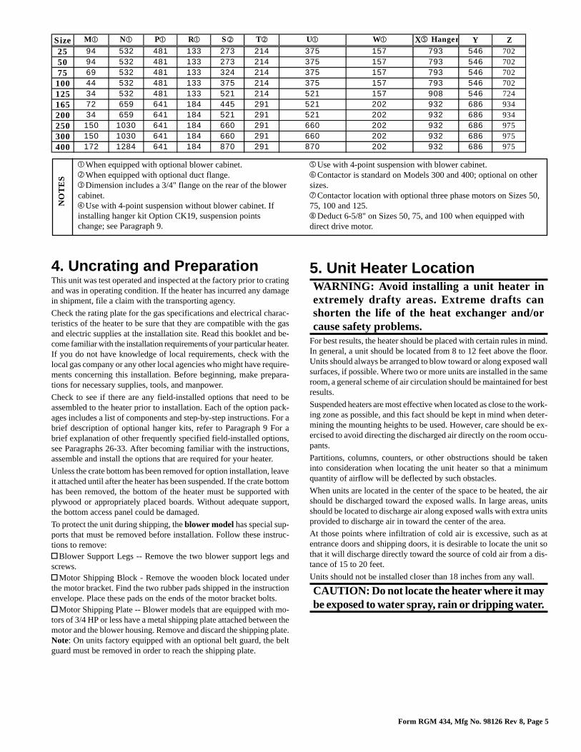
�Use with 4-point suspension with blower cabinet.�Contactor is standard on Models 300 and 400; optional on othersizes.�Contactor location with optional three phase motors on Sizes 50,75, 100 and 125.�Deduct 6-5/8" on Sizes 50, 75, and 100 when equipped withdirect drive motor.
NO
TE
S
�When equipped with optional blower cabinet.�When equipped with optional duct flange.�Dimension includes a 3/4" flange on the rear of the blowercabinet.�Use with 4-point suspension without blower cabinet. Ifinstalling hanger kit Option CK19, suspension pointschange; see Paragraph 9.
Size M� N� P� R� S� T� U� W� X� Hanger Y Z
25 94 532 481 133 273 214 375 793 546 702
50 94 532 481 133 273 214 375 793 546 702
75 69 532 481 133 324 214 375 793 546 702
100 44 532 481 133 375 214 375 793 546 702
125 34 532 481 133 521 214 521 908 546 724
165 72 659 641 184 445 291 521 932 686 934
200 34 659 641 184 521 291 521 932 686 934
250 150 1030 641 184 660 291 660 932 686 975
300 150 1030 641 184 660 291 660 932 686 975
400 172 1284 641 184 870 291 870 932 686 975
157157
202202
157157157202202202
5. Unit Heater LocationWARNING: Avoid installing a unit heater inextremely drafty areas. Extreme drafts canshorten the life of the heat exchanger and/orcause safety problems.
For best results, the heater should be placed with certain rules in mind.In general, a unit should be located from 8 to 12 feet above the floor.Units should always be arranged to blow toward or along exposed wallsurfaces, if possible. Where two or more units are installed in the sameroom, a general scheme of air circulation should be maintained for bestresults.
Suspended heaters are most effective when located as close to the work-ing zone as possible, and this fact should be kept in mind when deter-mining the mounting heights to be used. However, care should be ex-ercised to avoid directing the discharged air directly on the room occu-pants.
Partitions, columns, counters, or other obstructions should be takeninto consideration when locating the unit heater so that a minimumquantity of airflow will be deflected by such obstacles.
When units are located in the center of the space to be heated, the airshould be discharged toward the exposed walls. In large areas, unitsshould be located to discharge air along exposed walls with extra unitsprovided to discharge air in toward the center of the area.
At those points where infiltration of cold air is excessive, such as atentrance doors and shipping doors, it is desirable to locate the unit sothat it will discharge directly toward the source of cold air from a dis-tance of 15 to 20 feet.
Units should not be installed closer than 18 inches from any wall.
CAUTION: Do not locate the heater where it maybe exposed to water spray, rain or dripping water.

Form RGM 434, Mfg No. 98126 Rev 8, Page 6
8. Horizontal/Vertical Vent OutletAll heaters are designed for either a horizontal or vertical vent outlet.Sizes 25, 50, 75, 100, 165, and 200 are shipped with the vent outletinstalled in the horizontal position. Sizes 125, 250, 300, and 400 re-quire field assembly of the vent outlet. When the outlet is in the hori-zontal position, it is recommended that a 12-18" piece of straight pipebe connected to the outlet before installing an elbow.
WARNING: Sizes 125, 250, 300 and 400 requirefield assembly of the flue outlet. Follow theinstructions carefully. Failure to provide properventing could result in death, serious injury and/or property damage.
8.1 Horizontal/Vertical Vent Outlet -- Sizes25, 50, 75, 100, 165 and 200
The heater in these sizes is shipped with the vent outlet in the horizon-tal position. If a vertical vent outlet connection is needed, reverse thepositions of the flat cover plate and the flue collar assembly. See Fig-ure 2.
Figure 1 - ConfinedSpace: A spacewhose volume isless than 50 cubicfeet per 1000BTUH of theinstalled applianceinput rating
Sizes 25, 50, 75, 100,165, and 200 - Vent isfactory assembled inthe horizontal position.
Sizes 25, 50, 75, 100,165, and 200 -
Change the positionof the flue collar
assembly for avertical vent outlet
7. Combustion Air Requirementsfor a Heater Located in aConfined Space
Do not install a unit in a confined space without providing wall open-ings leading to and from the space. Provide openings near the floor andceiling for ventilation and air for combustion as shown in Figure 1,depending on the combustion air source as noted in Items 1, 2, and 3below the illustration.
Add total BTUH of all appliances in the confined space and divide byfigures below for square inch free area size of each (top and bottom)opening.
1. Air from inside the building -- openings 1 square inch free area per1000 BTUH. Never less than 100 square inches free area for each open-ing. See (1) in Figure 1.
2. Air from outside through duct -- openings 1 square inch free areaper 2000 BTUH. See (2) in Figure 1.
3. Air direct from outside -- openings 1 square inch free area per 4000BTUH. See (3) in Figure 1.
NOTE: For further details on supplying combustion air to a confinedspace, see the National Fuel Gas Code ANSI Z223.1a (latest edition ).
All fuel-burning equipment must be supplied with the air that entersinto the combustion process and is then vented to the outdoors. Suffi-cient air must enter the equipment location to replace that exhaustedthrough the heater vent system. In the past, the infiltration of outsideair assumed in heat loss calculations (one air change per hour) wasassumed to be sufficient. However, current construction methods uti-lizing more insulation, vapor barriers, tighter fitting and gasketed doorsand windows or weather-stripping, and mechanical exhaust fans maynow require the introduction of outside air through wall openings orducts.
The requirements for combustion and ventilation air depend uponwhether the unit is located in a confined or unconfined space. An "un-confined space" is defined as a space whose volume is not less than 50cubic feet per 1000 BTUH of the installed appliance. Under all condi-tions, enough air must be provided to ensure there will not be a nega-tive pressure condition within the equipment room or space. For spe-cific requirements for confined space installation, see Paragraph 7.
Notes: * Measure Top Clearance as illustrated.
** When supplied with optional downturn nozzle, bottom clear-ance is 42". For service purposes, on standard units, bottomclearance exceeding minimum (12") is not required but maybe desirable.
*** For servicing purposes only, rear must have 24" clearance.
6. Clearances and Combustion AirUnits must be installed so that the following clearances are provided for combustion air space, service and inspection, and for proper spacing fromcombustible construction.
Figure 2 - Vent Outlet Positions
Model Required ClearancesType Size Top Flue Connector Sides Bottom Rear
Fan 25 - 125 2" * 6" 18" 12" ** 24" ***165 - 400 6" * 6" 18" 12" ** 24" ***
Blower 25 - 400 6" * 6" 18" 12" ** 24" ***
Form RGM 434, Mfg No. 98126 Rev 8, Page 7
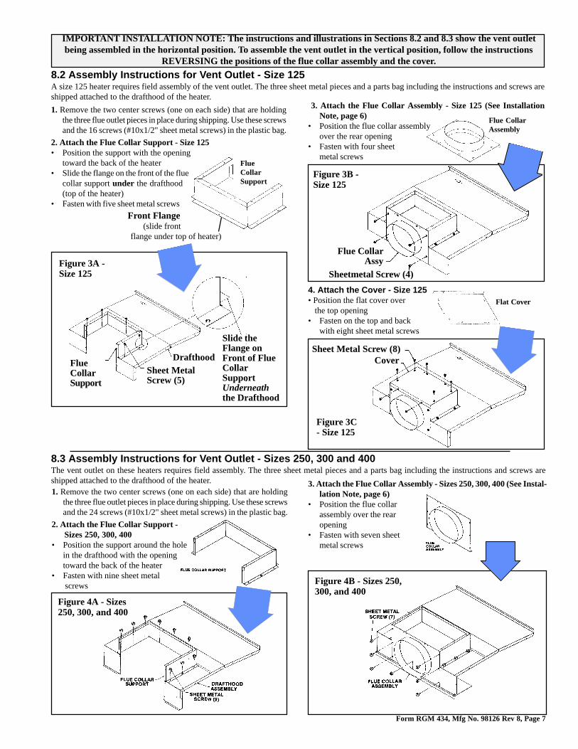
8.3 Assembly Instructions for Vent Outlet - Sizes 250, 300 and 400The vent outlet on these heaters requires field assembly. The three sheet metal pieces and a parts bag including the instructions and screws areshipped attached to the drafthood of the heater.1. Remove the two center screws (one on each side) that are holding
the three flue outlet pieces in place during shipping. Use these screwsand the 24 screws (#10x1/2" sheet metal screws) in the plastic bag.
2. Attach the Flue Collar Support -Sizes 250, 300, 400
• Position the support around the holein the drafthood with the openingtoward the back of the heater
• Fasten with nine sheet metal screws
4. Attach the Cover - Size 125• Position the flat cover over the top opening• Fasten on the top and back
with eight sheet metal screws
3. Attach the Flue Collar Assembly - Size 125 (See InstallationNote, page 6)
• Position the flue collar assemblyover the rear opening
• Fasten with four sheetmetal screws
Figure 3C- Size 125
Figure 3B -Size 125
Figure 4A - Sizes250, 300, and 400
Figure 4B - Sizes 250,300, and 400
Flue CollarAssembly
Flat Cover
Figure 3A -Size 125
DrafthoodSheet MetalScrew (5)
FlueCollarSupport
Slide theFlange onFront of FlueCollarSupportUnderneaththe Drafthood
IMPORTANT INSTALLATION NOTE: The instructions and illustrations in Sections 8.2 and 8.3 show the vent outletbeing assembled in the horizontal position. To assemble the vent outlet in the vertical position, follow the instructions
REVERSING the positions of the flue collar assembly and the cover.
8.2 Assembly Instructions for Vent Outlet - Size 125A size 125 heater requires field assembly of the vent outlet. The three sheet metal pieces and a parts bag including the instructions and screws areshipped attached to the drafthood of the heater.
1. Remove the two center screws (one on each side) that are holdingthe three flue outlet pieces in place during shipping. Use these screwsand the 16 screws (#10x1/2" sheet metal screws) in the plastic bag.
2. Attach the Flue Collar Support - Size 125• Position the support with the opening
toward the back of the heater• Slide the flange on the front of the flue
collar support under the drafthood(top of the heater)
• Fasten with five sheet metal screws
FlueCollarSupport
Front Flange(slide front
flange under top of heater)
Flue CollarAssy
Sheetmetal Screw (4)
Sheet Metal Screw (8)Cover
3. Attach the Flue Collar Assembly - Sizes 250, 300, 400 (See Instal-lation Note, page 6)
• Position the flue collarassembly over the rearopening
• Fasten with seven sheetmetal screws
Form RGM 434, Mfg No. 98126 Rev 8, Page 8
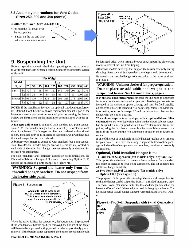
Figure 6 - Two-Point Suspension with Swivel Connections(fanmodelsonly)
Figure 5 - Suspension
9. Suspending the UnitBefore suspending the unit, check the supporting structure to be usedto verify that it has sufficient load-carrying capacity to support the weightof the unit.
NOTE: If the installation includes an optional stepdown transformerkit (Option CF or CG), the stepdown transformer bracket is part of theheater suspension and must be installed prior to hanging the heater.Follow the instructions on the installation sheet included with the op-tion kit.A fan-type unit heater is equipped with standard two-point suspen-sion. A 3/8-16 threaded hanger bracket assembly is located on eachside of the heater. If a fan-type unit has been ordered with optional,factory-installed, four-point suspension (Option BJ6), it will have twothreaded hanger brackets on each side.A blower-type heater is equipped with standard four-point suspen-sion. Two 3/8-16 threaded hanger bracket assemblies are located oneach side of the unit. Each hanger bracket assembly is designed forthreaded rod attachment.
For both "standard" and "optional" suspension point dimensions, seeDimension Tables in Paragraph 3. (Note: If installing Option CK19hanger kit, suspension points change; see Figure 7B.)
WARNING: Suspend the heater only from thethreaded hanger brackets. Do not suspend fromthe heater side panel.
When the heater is lifted for suspension, the bottom must be protected.If the wooden crate bottom has been removed, the bottom of the heaterwill have to be supported with plywood or other appropriately placedmaterial. If the bottom is not supported, the bottom access panel could
4. Attach the Cover - Sizes 250, 300, 400
• Position the flat cover over the top opening
• Fasten on the top and backwith ten sheet metal screws
Figure 4C -Sizes 250,300, and 400
8.3 Assembly Instructions for Vent Outlet -Sizes 250, 300 and 400 (cont'd)
be damaged. Also, when lifting a blower unit, support the blower andmotor to prevent the unit from tipping.
All blower models have legs that support the blower assembly duringshipping. After the unit is suspended, these legs should be removed.
Be sure that the threaded hanger rods are locked to the heater as shownin Figure 5.
WARNING: Unit must be level for proper operation.Do not place or add additional weight to thesuspended heater. See Hazard Levels, page 2.
If an optional downturn air nozzle is used, the unit must be suspendedfrom four points to ensure level suspension. Two hanger brackets areincluded in the downturn option package and must be field-installedon fan-type units with standard two-point suspension. For additionalinformation, refer to Paragraph 27 and the instructions that are fur-nished with the option package.When blower-type units are equipped with an optional blower/filtercabinet, there are two suspension points on the blower cabinet hangerbar. Suspend a unit equipped with a blower/filter cabinet from fourpoints, using the two heater hanger bracket assemblies closest to thefront of the heater and the two suspension points on the blower/filtercabinet.If one of the four optional, field-installed hanger kits has been orderedfor your heater, it will have been shipped separately. Each option pack-age includes a list of components and complete, step-by-step assemblyinstructions.
Optional, Field-Installed Hanger Kits:1) Four-Point Suspension (fan models only) - Option CK7This option kit is designed to convert a fan-type heater from standardtwo-point suspension to four-point suspension. The kit contains twoadditional hanger brackets.2) Two-Point Swivel Connectors (fan models only) -
Option CK8 (See Figure 6.)The purpose of this option kit is to adapt the standard hanger bracketso that the heater can be suspended from 1", threaded, stationary pipe.The swivel connector screws "into" the threaded hanger bracket on theheater and "onto" the 1" threaded pipe used for hanging the heater. Thekit includes two swivel hanger connector assemblies and two lock wash-ers.
Net Weight Size
25 50 75 100 125 165 200 250 300 400
Fan lbs 72 79 88 97 127 149 170 204 221 276
kg 33 36 40 44 58 68 77 93 100 125
Blower lbs 93 100 114 126 150 201 235 273 296 390
kg 42 45 52 57 68 91 107 124 134 177
Model Type

Form RGM 434, Mfg No. 98126 Rev 8, Page 9
3) Four-Point with Swivel Connectors (fan-modelsonly) - Option CK9 (See Figure 7A)
This option package is designed to convert a fan-type heater fromstandard two-point suspension to four-point suspension withswivel connectors. By installing this kit the standard fan-typeheater can be hung from four 1", threaded, stationary pipes. Thekit includes two hanger bracket assemblies, four swivel hangerconnector assemblies and four lock washers.4) Four-Point Swivel Connectors - Option CK10 (See
Figure 7A)This option package is used on a heater that is already equippedwith four-point suspension to adapt it for suspension from four1", threaded, stationary pipes. The kit includes four swivel hangerconnector assemblies and four lock washers.
5) Special Four-Point Suspension with Nearly EqualLoading (applies to blower models only) - OptionCK19
This suspension option is designed for special applications whena suspension system is needed that has nearly equal loading at allfour suspension points. Use this option in installations with springisolation designed for seismic protection or when threaded rodhangers are longer than twelve inches.
Suspension points change with the addition of hanger kit OptionCK19; see Figure 7B.
Figure 7A - Four-Point Suspension with SwivelConnections(Applies toboth fanand blowermodels)
Figure 7B - Suspension Dimensions for Model BHeater with Hanger Kit Option CK19
Size A B25-50 11-7/8 9-1/875 13-7/8 11-1/8100 15-7/8 13-1/8125 21-5/8 18-7/8165 18-5/8 15-7/8200 21-5/8 18-7/8250 27-1/8 24-3/8300 27-1/8 24-3/8400 35-3/8 32-5/8
10. VentingDANGER: Failure to provide proper venting could result in death, serious injury, and/or property damage.This heater must be installed with a vent connection and proper vent to the outside of the building. Installvent in accordance with Part 7, Venting of Equipment, of the National Fuel Gas Code, ANSI Z223.1 (latestedition) or applicable provision of national, state or local codes. A Canadian installation must be in accordancewith the CAN/CGA B149.1 and B149.2, Installation Code for Gas Burning Appliances and Equipment, andapplicable local codes. Also, follow venting recommendations listed below.Safe operation of any gravity-vented gas equipment requires a properly operating vent system, correctprovision for the combustion air (See Paragraphs 6-7) and regular maintenance and inspection (See page27). See Hazard Levels, page 2.
Heaters have the following vent outlet sizes:
Model Size
Size Configuration of Horizontal/Vertical Vent Outlet
25 - 50 4" Round
75 5" Oval
100 6" Oval
125 7" Oval
165 - 200 8" Oval
250 - 300 10" Oval
400 12" Oval
NOTE: Standard units manufactured prior to 10/89 (Serial No. Date Code prior to AOJ) have around fixed vertical vent outlet in the size listed.Units manufactured prior to 10/89 with OptionBT1 have the horizontal/vertical vent outlet.
Venting Requirements - All Models1. Provide a minimum clearance of 18" between the drafthood relief opening and any ob-
struction. Do not expose the relief opening to wind drafts from any source such as froman overhead door or adjacent air handling equipment.
2. The unit is equipped with a built-in draft diverter, consequently an external draft diverterMUST NOT be installed in the vent connector or any internal alterations made. Do notinstall a manual damper or other fixed restriction in the vent connector.
3. Vent pipe should be a minimum of 24 gauge galvanized steel or other non-corrosivematerial. Double wall, Type B vent such as Metalbestos or Amerivent is recommended.Where it is necessary to run the vent pipe through an exterior wall of combustible mate-rials, a suitable thimble must be used. The vent pipe shall have a clearance of at least sixinches from combustible materials, or as is specified by the double-wall vent pipe manu-facturer.
4. With the outlet on the heater in the horizontal position, it is recommended that a 12-18"piece of straight pipe be connected to the flue collar before installing an elbow. Thehorizontal vent pipe run should have a uniform rise of at least1/4" per foot of horizontal run in the direction of discharge. The length of the lateral run
Form RGM 434, Mfg No. 98126 Rev 8, Page 10
10. Venting (cont'd)Venting Requirements - All Models (cont'd)
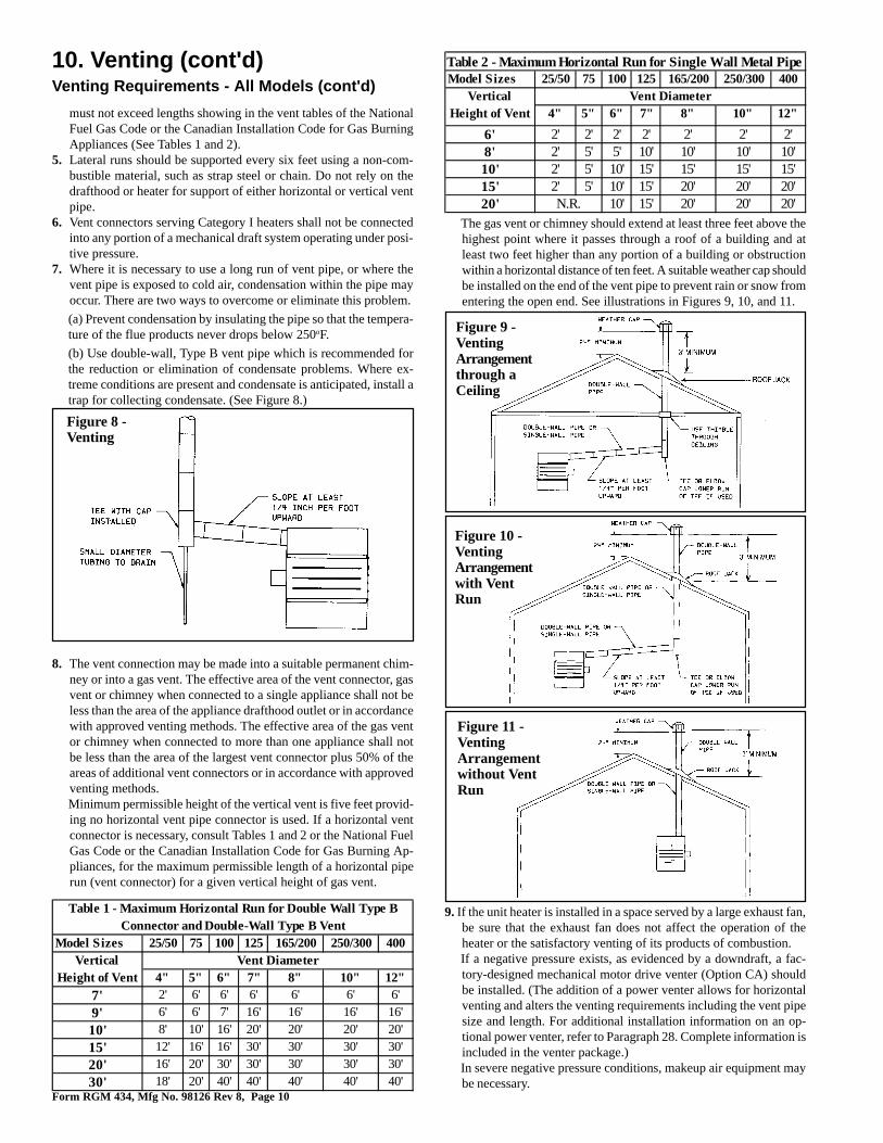
Figure 10 -VentingArrangementwith VentRun
Figure 11 -VentingArrangementwithout VentRun
The gas vent or chimney should extend at least three feet above thehighest point where it passes through a roof of a building and atleast two feet higher than any portion of a building or obstructionwithin a horizontal distance of ten feet. A suitable weather cap shouldbe installed on the end of the vent pipe to prevent rain or snow fromentering the open end. See illustrations in Figures 9, 10, and 11.
Figure 9 -VentingArrangementthrough aCeiling
Figure 8 -Venting
must not exceed lengths showing in the vent tables of the NationalFuel Gas Code or the Canadian Installation Code for Gas BurningAppliances (See Tables 1 and 2).
5. Lateral runs should be supported every six feet using a non-com-bustible material, such as strap steel or chain. Do not rely on thedrafthood or heater for support of either horizontal or vertical ventpipe.
6. Vent connectors serving Category I heaters shall not be connectedinto any portion of a mechanical draft system operating under posi-tive pressure.
7. Where it is necessary to use a long run of vent pipe, or where thevent pipe is exposed to cold air, condensation within the pipe mayoccur. There are two ways to overcome or eliminate this problem.
(a) Prevent condensation by insulating the pipe so that the tempera-ture of the flue products never drops below 250oF.
(b) Use double-wall, Type B vent pipe which is recommended forthe reduction or elimination of condensate problems. Where ex-treme conditions are present and condensate is anticipated, install atrap for collecting condensate. (See Figure 8.)
8. The vent connection may be made into a suitable permanent chim-ney or into a gas vent. The effective area of the vent connector, gasvent or chimney when connected to a single appliance shall not beless than the area of the appliance drafthood outlet or in accordancewith approved venting methods. The effective area of the gas ventor chimney when connected to more than one appliance shall notbe less than the area of the largest vent connector plus 50% of theareas of additional vent connectors or in accordance with approvedventing methods.Minimum permissible height of the vertical vent is five feet provid-ing no horizontal vent pipe connector is used. If a horizontal ventconnector is necessary, consult Tables 1 and 2 or the National FuelGas Code or the Canadian Installation Code for Gas Burning Ap-pliances, for the maximum permissible length of a horizontal piperun (vent connector) for a given vertical height of gas vent.
Table 1 - Maximum Horizontal Run for Double Wall Type BConnector and Double-Wall Type B Vent
Model Sizes 25/50 75 100 125 165/200 250/300 400Vertical Vent Diameter
Height of Vent 4" 5" 6" 7" 8" 10" 12"7' 2' 6' 6' 6' 6' 6' 6'
9' 6' 6' 7' 16' 16' 16' 16'
10' 8' 10' 16' 20' 20' 20' 20'
15' 12' 16' 16' 30' 30' 30' 30'
20' 16' 20' 30' 30' 30' 30' 30'
30' 18' 20' 40' 40' 40' 40' 40'
Table 2 - Maximum Horizontal Run for Single Wall Metal Pipe Model Sizes 25/50 75 100 125 165/200 250/300 400
Vertical Vent DiameterHeight of Vent 4" 5" 6" 7" 8" 10" 12"
6' 2' 2' 2' 2' 2' 2' 2'8' 2' 5' 5' 10' 10' 10' 10'10' 2' 5' 10' 15' 15' 15' 15'15' 2' 5' 10' 15' 20' 20' 20'20' N.R. 10' 15' 20' 20' 20'
9. If the unit heater is installed in a space served by a large exhaust fan,be sure that the exhaust fan does not affect the operation of theheater or the satisfactory venting of its products of combustion.If a negative pressure exists, as evidenced by a downdraft, a fac-tory-designed mechanical motor drive venter (Option CA) shouldbe installed. (The addition of a power venter allows for horizontalventing and alters the venting requirements including the vent pipesize and length. For additional installation information on an op-tional power venter, refer to Paragraph 28. Complete information isincluded in the venter package.)In severe negative pressure conditions, makeup air equipment maybe necessary.
Form RGM 434, Mfg No. 98126 Rev 8, Page 11
11. Gas Piping and Pressures
All piping must be in accordance with requirements outlined in theNational Fuel Gas Code ANSI/Z223.1a (latest edition), published bythe American Gas Association or CAN/CGA-B149.1 and B149.2, pub-lished by the Canadian Gas Association (See Paragraph 1). Gas supplypiping installation should conform with good practice and with localcodes.
Unit heaters for natural gas are orificed for operation with gas having aheating value of 1000 (+ or - 50) BTUH per cubic ft. If the gas at theinstallation does not meet this specification, consult the factory forproper orificing.
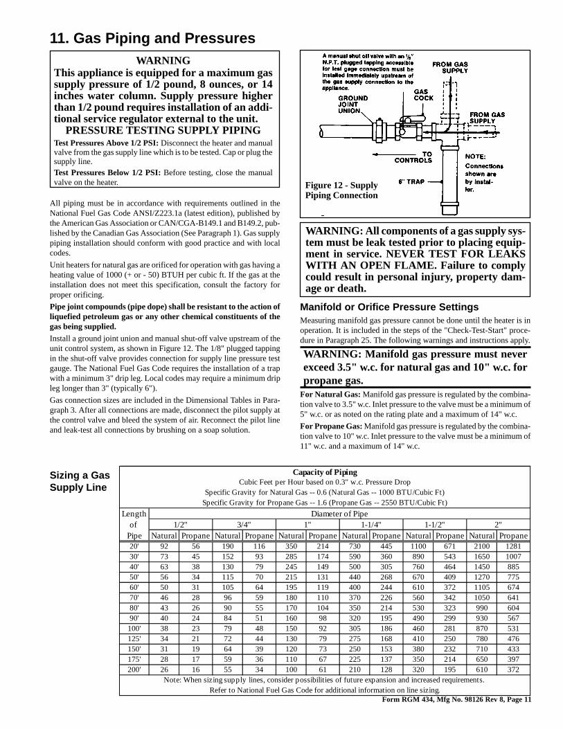
Pipe joint compounds (pipe dope) shall be resistant to the action ofliquefied petroleum gas or any other chemical constituents of thegas being supplied.Install a ground joint union and manual shut-off valve upstream of theunit control system, as shown in Figure 12. The 1/8" plugged tappingin the shut-off valve provides connection for supply line pressure testgauge. The National Fuel Gas Code requires the installation of a trapwith a minimum 3" drip leg. Local codes may require a minimum dripleg longer than 3" (typically 6").
Gas connection sizes are included in the Dimensional Tables in Para-graph 3. After all connections are made, disconnect the pilot supply atthe control valve and bleed the system of air. Reconnect the pilot lineand leak-test all connections by brushing on a soap solution.
WARNINGThis appliance is equipped for a maximum gassupply pressure of 1/2 pound, 8 ounces, or 14inches water column. Supply pressure higherthan 1/2 pound requires installation of an addi-tional service regulator external to the unit.
PRESSURE TESTING SUPPLY PIPINGTest Pressures Above 1/2 PSI: Disconnect the heater and manualvalve from the gas supply line which is to be tested. Cap or plug thesupply line.Test Pressures Below 1/2 PSI: Before testing, close the manualvalve on the heater.
WARNING: All components of a gas supply sys-tem must be leak tested prior to placing equip-ment in service. NEVER TEST FOR LEAKSWITH AN OPEN FLAME. Failure to complycould result in personal injury, property dam-age or death.
Figure 12 - SupplyPiping Connection
Manifold or Orifice Pressure SettingsMeasuring manifold gas pressure cannot be done until the heater is inoperation. It is included in the steps of the "Check-Test-Start" proce-dure in Paragraph 25. The following warnings and instructions apply.
WARNING: Manifold gas pressure must neverexceed 3.5" w.c. for natural gas and 10" w.c. forpropane gas.
For Natural Gas: Manifold gas pressure is regulated by the combina-tion valve to 3.5" w.c. Inlet pressure to the valve must be a minimum of5" w.c. or as noted on the rating plate and a maximum of 14" w.c.
For Propane Gas: Manifold gas pressure is regulated by the combina-tion valve to 10" w.c. Inlet pressure to the valve must be a minimum of11" w.c. and a maximum of 14" w.c.
Sizing a GasSupply Line
Capacity of PipingCubic Feet per Hour based on 0.3" w.c. Pressure Drop
Specific Gravity for Natural Gas -- 0.6 (Natural Gas -- 1000 BTU/Cubic Ft)Specific Gravity for Propane Gas -- 1.6 (Propane Gas -- 2550 BTU/Cubic Ft)
Length Diameter of Pipeof 1/2" 3/4" 1" 1-1/4" 1-1/2" 2"
Pipe Natural Propane Natural Propane Natural Propane Natural Propane Natural Propane Natural Propane20' 92 56 190 116 350 214 730 445 1100 671 2100 128130' 73 45 152 93 285 174 590 360 890 543 1650 100740' 63 38 130 79 245 149 500 305 760 464 1450 88550' 56 34 115 70 215 131 440 268 670 409 1270 77560' 50 31 105 64 195 119 400 244 610 372 1105 67470' 46 28 96 59 180 110 370 226 560 342 1050 64180' 43 26 90 55 170 104 350 214 530 323 990 60490' 40 24 84 51 160 98 320 195 490 299 930 567100' 38 23 79 48 150 92 305 186 460 281 870 531125' 34 21 72 44 130 79 275 168 410 250 780 476150' 31 19 64 39 120 73 250 153 380 232 710 433175' 28 17 59 36 110 67 225 137 350 214 650 397200' 26 16 55 34 100 61 210 128 320 195 610 372
Note: When sizing supply lines, consider possibilities of future expansion and increased requirements. Refer to National Fuel Gas Code for additional information on line sizing.
Form RGM 434, Mfg No. 98126 Rev 8, Page 12
11. Gas Piping and Pressures (cont'd)is recommended rather than a spring type gauge due to the difficulty ofmaintaining calibration of a spring type gauge.2) Open the valve and operate the heater. Measure the gas pressure tothe manifold. Normally adjustments should not be necessary to thefactory preset regulator.If adjustment is necessary, set pressure to correct settings by turningthe regulator screw IN (clockwise) to increase pressure. Turn regulatorscrew OUT (counterclockwise) to decrease pressure.Consult the valve manufacturer's literature provided with the heaterfor more detailed information.
Threaded Hole forStandard 1/2"Electrical Fitting
Remove AccessPanel to Make
Connections
WARNINGS: On a heater witha unit disconnect switch(Option AI-1), if the power isturned off at the switch, thesupply lead in the electricalsupply junction box (Figure13A) remains energized. Ifservice is to be done in thesupply junction box, turn off thepower at the remote disconnectswitch.If you turn off the power supply,turn off the gas.Specific wiring diagrams that include standardand factory-installed options are on with theheater. Check the wiring diagram to identifyoptional equipment.The operating sequence of the heater can befound on the heater wiring diagram and is pub-lished in Paragraph 25, Check Installation andStart-Up. Typical wiring diagrams are on the
next six pages, showing standard single-stage heating with standard match-lit pilot and optional intermittent spark pilot with and without lockout.
12. Electrical Supply and ConnectionsAll electrical wiring and connections, including electrical ground-ing MUST be made in accordance with the National ElectricCode ANSI/NFPA No. 70 (latest edition) or, in Canada, the Ca-nadian Electrical Code, Part I-C.S.A. Standard C22.1. In addi-tion, the installer should be aware of any local ordinances or gascompany requirements that might apply.
Check the rating plate on the heater for the supply voltage andcurrent requirements. A separate line voltage supply with fuseddisconnect switch should be run directly from the main electricalpanel to the heater. All external wiring must be within approvedconduit and have a minimum temperature rise of 60oC. Conduitfrom the disconnect switch must be run so as not to interferewith the service panels of the heater.
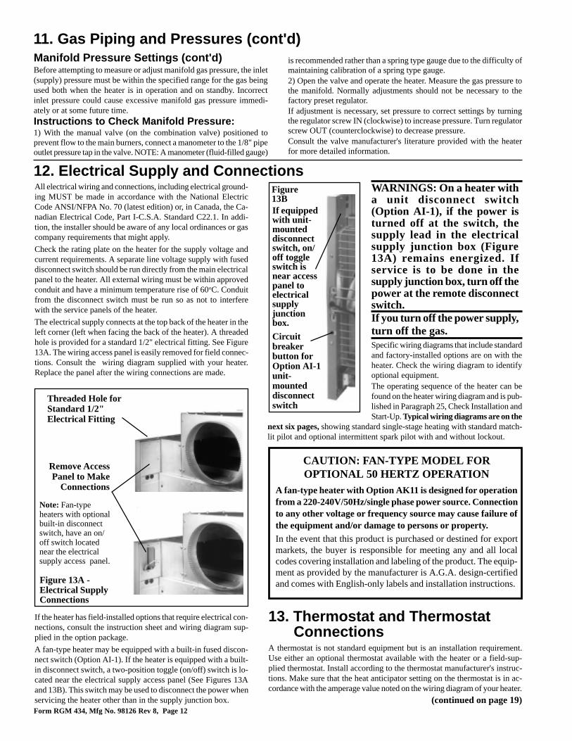
The electrical supply connects at the top back of the heater in theleft corner (left when facing the back of the heater). A threadedhole is provided for a standard 1/2" electrical fitting. See Figure13A. The wiring access panel is easily removed for field connec-tions. Consult the wiring diagram supplied with your heater.Replace the panel after the wiring connections are made.
If the heater has field-installed options that require electrical con-nections, consult the instruction sheet and wiring diagram sup-plied in the option package.
A fan-type heater may be equipped with a built-in fused discon-nect switch (Option AI-1). If the heater is equipped with a built-in disconnect switch, a two-position toggle (on/off) switch is lo-cated near the electrical supply access panel (See Figures 13Aand 13B). This switch may be used to disconnect the power whenservicing the heater other than in the supply junction box.
CAUTION: FAN-TYPE MODEL FOROPTIONAL 50 HERTZ OPERATION
A fan-type heater with Option AK11 is designed for operationfrom a 220-240V/50Hz/single phase power source. Connectionto any other voltage or frequency source may cause failure ofthe equipment and/or damage to persons or property.In the event that this product is purchased or destined for exportmarkets, the buyer is responsible for meeting any and all localcodes covering installation and labeling of the product. The equip-ment as provided by the manufacturer is A.G.A. design-certifiedand comes with English-only labels and installation instructions.Figure 13A -
Electrical SupplyConnections
Note: Fan-typeheaters with optionalbuilt-in disconnectswitch, have an on/off switch locatednear the electricalsupply access panel.
Figure13BIf equippedwith unit-mounteddisconnectswitch, on/off toggleswitch isnear accesspanel toelectricalsupplyjunctionbox.
Circuitbreakerbutton forOption AI-1unit-mounteddisconnectswitch
Manifold Pressure Settings (cont'd)Before attempting to measure or adjust manifold gas pressure, the inlet(supply) pressure must be within the specified range for the gas beingused both when the heater is in operation and on standby. Incorrectinlet pressure could cause excessive manifold gas pressure immedi-ately or at some future time.Instructions to Check Manifold Pressure:1) With the manual valve (on the combination valve) positioned toprevent flow to the main burners, connect a manometer to the 1/8" pipeoutlet pressure tap in the valve. NOTE: A manometer (fluid-filled gauge)
13. Thermostat and ThermostatConnections
A thermostat is not standard equipment but is an installation requirement.Use either an optional thermostat available with the heater or a field-sup-plied thermostat. Install according to the thermostat manufacturer's instruc-tions. Make sure that the heat anticipator setting on the thermostat is in ac-cordance with the amperage value noted on the wiring diagram of your heater.
(continued on page 19)
Form RGM 434, Mfg No. 98126 Rev 8, Page 13
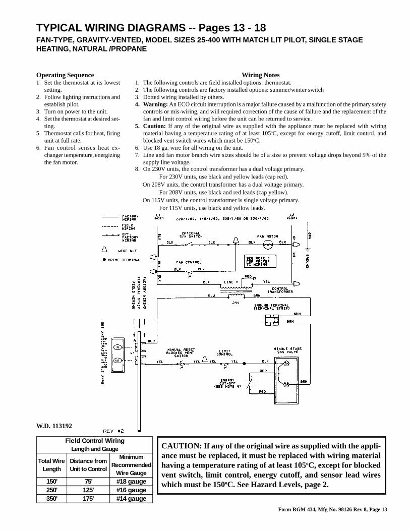
TYPICAL WIRING DIAGRAMS -- Pages 13 - 18FAN-TYPE, GRAVITY-VENTED, MODEL SIZES 25-400 WITH MATCH LIT PILOT, SINGLE STAGEHEATING, NATURAL /PROPANE
Wiring Notes1. The following controls are field installed options: thermostat.2. The following controls are factory installed options: summer/winter switch3. Dotted wiring installed by others.4. Warning: An ECO circuit interruption is a major failure caused by a malfunction of the primary safety
controls or mis-wiring, and will required correction of the cause of failure and the replacement of thefan and limit control wiring before the unit can be returned to service.
5. Caution: If any of the original wire as supplied with the appliance must be replaced with wiringmaterial having a temperature rating of at least 105oC, except for energy cutoff, limit control, andblocked vent switch wires which must be 150oC.
6. Use 18 ga. wire for all wiring on the unit.7. Line and fan motor branch wire sizes should be of a size to prevent voltage drops beyond 5% of the
supply line voltage.8. On 230V units, the control transformer has a dual voltage primary.
For 230V units, use black and yellow leads (cap red). On 208V units, the control transformer has a dual voltage primary.
For 208V units, use black and red leads (cap yellow). On 115V units, the control transformer is single voltage primary.
For 115V units, use black and yellow leads.
Operating Sequence1. Set the thermostat at its lowest
setting.2. Follow lighting instructions and
establish pilot.3. Turn on power to the unit.4. Set the thermostat at desired set-
ting.5. Thermostat calls for heat, firing
unit at full rate.6. Fan control senses heat ex-
changer temperature, energizingthe fan motor.
CAUTION: If any of the original wire as supplied with the appli-ance must be replaced, it must be replaced with wiring materialhaving a temperature rating of at least 105oC, except for blockedvent switch, limit control, energy cutoff, and sensor lead wireswhich must be 150oC. See Hazard Levels, page 2.
W.D. 113192
Field Control WiringLength and Gauge
Total Wire Length
Distance from Unit to Control
Minimum Recommended
Wire Gauge150' 75' #18 gauge250' 125' #16 gauge350' 175' #14 gauge
Form RGM 434, Mfg No. 98126 Rev 8, Page 14
FAN CONTROL
BK
L1(HOT)
BK
BK
R
24V
LINE VOLT
BR
R
Y
BK
GROUND TERMINAL(TERMINAL STRIP)
L2(COM)
220/1/50, 115/1/60, 208/1/60 OR 230/1/60
BR
R
SE
T A
NT
ICIP
ATO
R A
T 0
.8 A
MP
SW
.R. 1
C30
-339
TH
ER
MO
STA
T
W1
R
W1
Y Y
LIMITCONTROL
Y
GRND.
RECYCLE ORG67BG-5
LOCKOUT
IGNITION
CHASSIS GRND.
CONTROLLER
G770NGC-4
1
3
2
4
W
PROBE
GRND
IGNITOR
STRIP
FLAME SENSING
BR
R
BK
FIE
LD W
IRIN
G
TE
RM
INA
L S
TR
IP
FAC
TOR
Y W
IRIN
G
F25 THRU 400 OPT. AH2/AH3 WD #113201 REV #3
WW
BK
BK
BR
GRD
G
FAN MOTOR
BK
BR
BK
BLOCKED VENTMANUAL RESET
SWITCH
Y
BK
ALT
ER
NA
TE
HO
NE
YW
ELL
RE
DU
ND
AN
T G
AS
VA
LVE
BL
PIL
OT
OR PVTH-TR
TH ORMV
BR PV-MVTR OR
MA
IN
BK BKS/W SWITCH
OPTIONAL
PIL
OT
W.R
. OR
RO
BE
RT
SH
AW
RE
DU
ND
AN
T G
AS
VA
LVE
P
MA
IN
M
C
BL
CONTROLTRANSFORMER
OPTIONAL FIELD WIRING
OPTIONAL FACTORY WIRING
FACTORY WIRING
FIELD WIRING
WIRE NUT
CRIMP TERMINAL
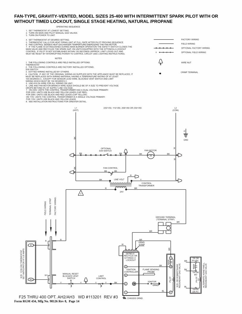
3
OPERATING SEQUENCE
1. SET THERMOSTAT AT LOWEST SETTING.2. TURN ON MAIN AND PILOT MANUAL GAS VALVES.3. TURN ON POWER TO UNIT.
4. SET THERMOSTAT AT DESIRED SETTING.5. THERMOSTAT CALLS FOR HEAT FIRING UNIT AT FULL RATE AFTER PILOT PROVING SEQUENCE.
7. IF THE FLAME IS EXTINGUISHED DURING MAIN BURNER OPERATION THE SAFETY SWITCH CLOSES THEMAIN VALVE AND RECYCLES THE SPARK GAP. ON UNITS EQUIPPED WITH THE G77ONCG-4 LOCKOUTCONTROL, IF PILOT IS NOT ESTABLISHED WITHIN 120 SECONDS (APPROX.) UNIT LOCKS OUT ANDMUST BE RESET BY INTERRUPTING POWER TO CONTROL CIRCUIT (SEE LIGHTING INSTRUCTIONS).
6. FAN CONTROL SENSES HEAT EXCHANGER TEMPERTURE ENERGIZING THE FAN MOTOR.
NOTES
1. THE FOLLOWING CONTROLS ARE FIELD INSTALLED OPTIONS:THERMOSTAT2. THE FOLLOWING CONTROLS ARE FACTORY INSTALLED OPTIONS:S/W SWITCH3. DOTTED WIRING INSTALLED BY OTHERS.4. CAUTION: IF ANY OF THE ORIGINAL WIRING AS SUPPLIED WITH THE APPLIANCE MUST BE REPLACED, ITMUST BE REPLACED WITH WIRING MATERIAL HAVING A TEMPERATURE RATING OF AT LEAST105 DEGREES C., EXCEPT FOR SENSOR LEAD WIRE, BLOCKED VENT SWITCH AND LIMITWIRING WHICH MUST BE 150 DEGREES C.5. USE #18 GA WIRE FOR ALL WIRING ON UNIT..6. LINE AND FAN MOTOR BRANCH WIRE SIZES SHOULD BE OF A SIZE TO PREVENT VOLTAGEDROPS BEYOND 5% OF SUPPLY LINE VOLTAGE.
8. SEE INSTALLATION INSTRUCTIONS FOR GREATER DETAIL.
ON 115V. UNITS THE CONTROL TRANSFORMER IS A SINGLE VOLTAGE PRIMARY.
7. ON 230V. UNITS THE CONTROL TRANSFORMER HAS A DUAL VOLTAGE PRIMARY.
FOR 115V. UNITS USE BLACK AND YELLOW LEADS.
FOR 208V. UNITS USE BLACK AND RED LEADS (CAP YELLOW).FOR 230V. UNITS USE BLACK AND YELLOW LEADS (CAP RED).
FAN-TYPE, GRAVITY-VENTED, MODEL SIZES 25-400 WITH INTERMITTENT SPARK PILOT WITH ORWITHOUT TIMED LOCKOUT, SINGLE STAGE HEATING, NATURAL /PROPANE
Form RGM 434, Mfg No. 98126 Rev 8, Page 15
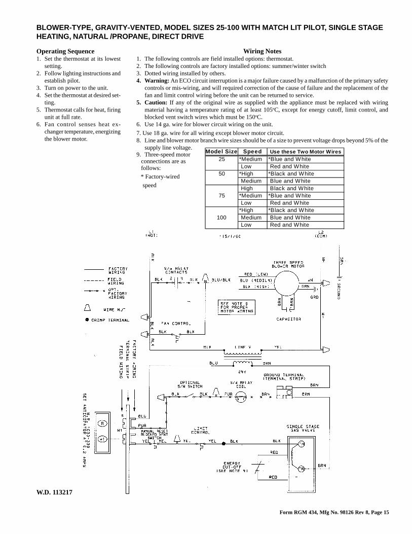
BLOWER-TYPE, GRAVITY-VENTED, MODEL SIZES 25-100 WITH MATCH LIT PILOT, SINGLE STAGEHEATING, NATURAL /PROPANE, DIRECT DRIVE
Operating Sequence1. Set the thermostat at its lowest
setting.2. Follow lighting instructions and
establish pilot.3. Turn on power to the unit.4. Set the thermostat at desired set-
ting.5. Thermostat calls for heat, firing
unit at full rate.6. Fan control senses heat ex-
changer temperature, energizingthe blower motor.
W.D. 113217
Wiring Notes1. The following controls are field installed options: thermostat.2. The following controls are factory installed options: summer/winter switch3. Dotted wiring installed by others.4. Warning: An ECO circuit interruption is a major failure caused by a malfunction of the primary safety
controls or mis-wiring, and will required correction of the cause of failure and the replacement of thefan and limit control wiring before the unit can be returned to service.
5. Caution: If any of the original wire as supplied with the appliance must be replaced with wiringmaterial having a temperature rating of at least 105oC, except for energy cutoff, limit control, andblocked vent switch wires which must be 150oC.
6. Use 14 ga. wire for blower circuit wiring on the unit.
7. Use 18 ga. wire for all wiring except blower motor circuit.8. Line and blower motor branch wire sizes should be of a size to prevent voltage drops beyond 5% of the
supply line voltage.9. Three-speed motor connections are as follows:
* Factory-wired
speed
Model Size Speed Use these Two Motor Wires25 *Medium *Blue and White
Low Red and White50 *High *Black and White
Medium Blue and White High Black and White
75 *Medium *Blue and White Low Red and White*High *Black and White
100 Medium Blue and White Low Red and White
Form RGM 434, Mfg No. 98126 Rev 8, Page 16
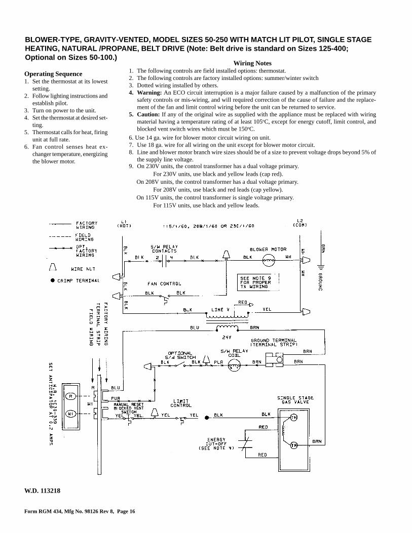
BLOWER-TYPE, GRAVITY-VENTED, MODEL SIZES 50-250 WITH MATCH LIT PILOT, SINGLE STAGEHEATING, NATURAL /PROPANE, BELT DRIVE (Note: Belt drive is standard on Sizes 125-400;Optional on Sizes 50-100.)
Wiring Notes1. The following controls are field installed options: thermostat.2. The following controls are factory installed options: summer/winter switch3. Dotted wiring installed by others.4. Warning: An ECO circuit interruption is a major failure caused by a malfunction of the primary
safety controls or mis-wiring, and will required correction of the cause of failure and the replace-ment of the fan and limit control wiring before the unit can be returned to service.
5. Caution: If any of the original wire as supplied with the appliance must be replaced with wiringmaterial having a temperature rating of at least 105oC, except for energy cutoff, limit control, andblocked vent switch wires which must be 150oC.
6. Use 14 ga. wire for blower motor circuit wiring on unit.7. Use 18 ga. wire for all wiring on the unit except for blower motor circuit.8. Line and blower motor branch wire sizes should be of a size to prevent voltage drops beyond 5% of
the supply line voltage.9. On 230V units, the control transformer has a dual voltage primary.
For 230V units, use black and yellow leads (cap red). On 208V units, the control transformer has a dual voltage primary.
For 208V units, use black and red leads (cap yellow). On 115V units, the control transformer is single voltage primary.
For 115V units, use black and yellow leads.
W.D. 113218
Operating Sequence1. Set the thermostat at its lowest
setting.2. Follow lighting instructions and
establish pilot.3. Turn on power to the unit.4. Set the thermostat at desired set-
ting.5. Thermostat calls for heat, firing
unit at full rate.6. Fan control senses heat ex-
changer temperature, energizingthe blower motor.
Form RGM 434, Mfg No. 98126 Rev 8, Page 17
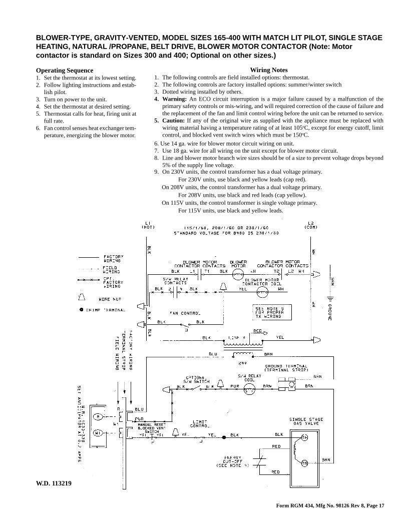
Wiring Notes1. The following controls are field installed options: thermostat.2. The following controls are factory installed options: summer/winter switch3. Dotted wiring installed by others.4. Warning: An ECO circuit interruption is a major failure caused by a malfunction of the
primary safety controls or mis-wiring, and will required correction of the cause of failure andthe replacement of the fan and limit control wiring before the unit can be returned to service.
5. Caution: If any of the original wire as supplied with the appliance must be replaced withwiring material having a temperature rating of at least 105oC, except for energy cutoff, limitcontrol, and blocked vent switch wires which must be 150oC.
6. Use 14 ga. wire for blower motor circuit wiring on unit.7. Use 18 ga. wire for all wiring on the unit except for blower motor circuit.8. Line and blower motor branch wire sizes should be of a size to prevent voltage drops beyond
5% of the supply line voltage.9. On 230V units, the control transformer has a dual voltage primary.
For 230V units, use black and yellow leads (cap red). On 208V units, the control transformer has a dual voltage primary.
For 208V units, use black and red leads (cap yellow). On 115V units, the control transformer is single voltage primary.
For 115V units, use black and yellow leads.
BLOWER-TYPE, GRAVITY-VENTED, MODEL SIZES 165-400 WITH MATCH LIT PILOT, SINGLE STAGEHEATING, NATURAL /PROPANE, BELT DRIVE, BLOWER MOTOR CONTACTOR (Note: Motorcontactor is standard on Sizes 300 and 400; Optional on other sizes.)
W.D. 113219
Operating Sequence1. Set the thermostat at its lowest setting.2. Follow lighting instructions and estab-
lish pilot.3. Turn on power to the unit.4. Set the thermostat at desired setting.5. Thermostat calls for heat, firing unit at
full rate.6. Fan control senses heat exchanger tem-
perature, energizing the blower motor.

Form RGM 434, Mfg No. 98126 Rev 8, Page 18
BLOWER-TYPE, GRAVITY-VENTED, MODEL SIZES 25-400 WITH INTERMITTENT SPARK PILOTWITH OR WITHOUT TIMED LOCKOUT (For line voltage wiring, refer to the corresponding diagramshowing match-lit pilot.)Operating Sequence1. Set the thermostat at its low-
est setting.2. Follow lighting instructions
and establish pilot.3. Turn on power to the unit.4. Set the thermostat at desired
setting.5. Thermostat calls for heat,
firing unit at full rate.6. Fan control senses heat ex-
changer temperature, ener-gizing the blower motor.
Wiring Notes1. The following controls are field installed options: thermostat.2. The following controls are factory installed options: summer/winter switch3. Dotted wiring installed by others.4. Caution: If any of the original wire as supplied with the appliance must be replaced with wiring material
having a temperature rating of at least 105oC, except for energy cutoff, limit control, and blocked ventswitch wires which must be 150oC.
5. Use 14 ga. wire for blower motor circuit wiring on unit.6. Use 18 ga. wire for all wiring on the unit except for blower motor circuit.7. Line and blower motor branch wire sizes should be of a size to prevent voltage drops beyond 5% of the
supply line voltage.8. On 230V units, the control transformer has a dual voltage primary.
For 230V units, use black and yellow leads (cap red). On 208V units, the control transformer has a dual voltage primary.
For 208V units, use black and red leads (cap yellow). On 115V units, the control transformer is single voltage primary.
For 115V units, use black and yellow leads.
Form RGM 434, Mfg No. 98126 Rev 8, Page 19
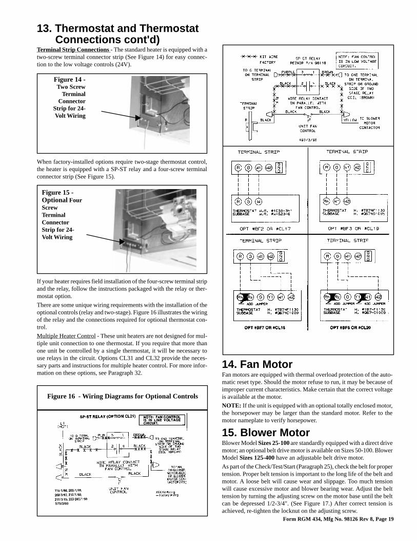
Terminal Strip Connections - The standard heater is equipped with atwo-screw terminal connector strip (See Figure 14) for easy connec-tion to the low voltage controls (24V).
When factory-installed options require two-stage thermostat control,the heater is equipped with a SP-ST relay and a four-screw terminalconnector strip (See Figure 15).
If your heater requires field installation of the four-screw terminal stripand the relay, follow the instructions packaged with the relay or ther-mostat option.
There are some unique wiring requirements with the installation of theoptional controls (relay and two-stage). Figure 16 illustrates the wiringof the relay and the connections required for optional thermostat con-trol.
Multiple Heater Control - These unit heaters are not designed for mul-tiple unit connection to one thermostat. If you require that more thanone unit be controlled by a single thermostat, it will be necessary touse relays in the circuit. Options CL31 and CL32 provide the neces-sary parts and instructions for multiple heater control. For more infor-mation on these options, see Paragraph 32.
Figure 15 -Optional FourScrewTerminalConnectorStrip for 24-Volt Wiring
Figure 16 - Wiring Diagrams for Optional Controls
575/3/60
13. Thermostat and ThermostatConnections cont'd)
Figure 14 -Two Screw
TerminalConnector
Strip for 24-Volt Wiring
14. Fan MotorFan motors are equipped with thermal overload protection of the auto-matic reset type. Should the motor refuse to run, it may be because ofimproper current characteristics. Make certain that the correct voltageis available at the motor.
NOTE: If the unit is equipped with an optional totally enclosed motor,the horsepower may be larger than the standard motor. Refer to themotor nameplate to verify horsepower.
15. Blower MotorBlower Model Sizes 25-100 are standardly equipped with a direct drivemotor; an optional belt drive motor is available on Sizes 50-100. BlowerModel Sizes 125-400 have an adjustable belt drive motor.
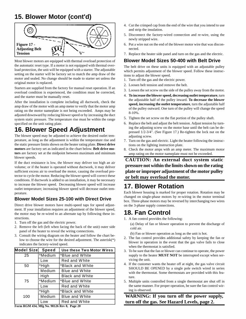
As part of the Check/Test/Start (Paragraph 25), check the belt for propertension. Proper belt tension is important to the long life of the belt andmotor. A loose belt will cause wear and slippage. Too much tensionwill cause excessive motor and blower bearing wear. Adjust the belttension by turning the adjusting screw on the motor base until the beltcan be depressed 1/2-3/4". (See Figure 17.) After correct tension isachieved, re-tighten the locknut on the adjusting screw.
Form RGM 434, Mfg No. 98126 Rev 8, Page 20
17. Blower RotationEach blower housing is marked for proper rotation. Rotation may bechanged on single-phase motors by re-wiring in the motor terminalbox. Three-phase motors may be reversed by interchanging two wireson the 3-phase supply connections.
18. Fan Control1. A fan control provides the following:
(a) Delay of fan or blower operation to prevent the discharge ofcold air.
(b) Fan or blower operation as long as the unit is hot.2. The fan control provides additional safety by keeping the fan or
blower in operation in the event that the gas valve fails to closewhen the thermostat is satisfied.
3. To be sure that the fan or blower can continue to operate, the powersupply to the heater MUST NOT be interrupted except when ser-vicing the unit.
4. If the customer wants the heater off at night, the gas valve circuitSHOULD BE OPENED by a single pole switch wired in serieswith the thermostat. Some thermostats are provided with this fea-ture.
5. Multiple units controlled from a single thermostat are shut off inthe same manner. For proper operation, be sure the fan control wir-ing is observed.
WARNING: If you turn off the power supply,turn off the gas. See Hazard Levels, page 2.
16. Blower Speed AdjustmentThe blower speed may be adjusted to achieve the desired outlet tem-perature, as long as the adjustment is within the temperature rise andthe static pressure limits shown on the heater rating plate. Direct drivemotors are factory set as indicated in the chart below. Belt drive mo-tors are factory set at the midpoint between maximum and minimumblower speeds.
If the duct resistance is low, the blower may deliver too high an airvolume; or if the heater is operated without ductwork, it may deliversufficient excess air to overload the motor, causing the overload pro-tector to cycle the motor. Reducing the blower speed will correct theseconditions. If ductwork is added to an installation, it may be necessaryto increase the blower speed. Decreasing blower speed will increaseoutlet temperature; increasing blower speed will decrease outlet tem-perature.
Blower Model Sizes 25-100 with Direct DriveDirect drive blower motors have multi-speed taps for speed adjust-ment. If your installation requires an adjustment of the blower speed,the motor may be re-wired to an alternate tap by following these in-structions.1. Turn off the gas and the electric power.2. Remove the left (left when facing the back of the unit) outer side
panel of the heater to reveal the wiring connections.3. Consult the wiring diagram on the heater and follow the chart be-
low to choose the wire for the desired adjustment. The asterisk(*)indicates the factory-wired speed.
Figure 17 -Adjusting BeltTension
4. Cut the crimped cap from the end of the wire that you intend to useand strip the insulation.
5. Disconnect the factory-wired connection and re-wire, using thenewly stripped wire.
6. Put a wire nut on the end of the blower motor wire that was discon-nected.
7. Replace the heater side panel and turn on the gas and the electric.
Blower Model Sizes 50-400 with Belt DriveThe belt drive on these units is equipped with an adjustable pulleywhich permits adjustment of the blower speed. Follow these instruc-tions to adjust the blower speed.1. Turn off the gas and the electric power.
2. Loosen belt tension and remove the belt.
3. Loosen the set screw on the side of the pulley away from the motor.
4. To increase the blower speed, decreasing outlet temperature, turnthe adjustable half of the pulley inward. To decrease the blowerspeed, increasing the outlet temperature, turn the adjustable halfof the pulley outward. One turn of the pulley will change the speed8-10%.
5. Tighten the set screw on the flat portion of the pulley shaft.
6. Replace the belt and adjust the belt tension. Adjust tension by turn-ing the adjusting screw on the motor base until the belt can be de-pressed 1/2-3/4". (See Figure 17.) Re-tighten the lock nut on theadjusting screw.
7. Turn on the gas and electric. Light the heater following the instruc-tions on the lighting instruction plate.
8. Check the motor amps with an amp meter. The maximum motoramp rating on the motor nameplate must not be exceeded.
CAUTION: An external duct system staticpressure not within the limits shown on the ratingplate or improper adjustment of the motor pulleyor belt may overload the motor.
Most blower motors are equipped with thermal overload protection ofthe automatic reset type. If a motor is not equipped with thermal over-load protection, the unit will be equipped with a starter. The adjustablesetting on the starter will be factory set to match the amp draw of themotor and sealed. No change should be made to starter set unless theoriginal motor is replaced.
Starters are supplied from the factory for manual reset operation. If anoverload condition is experienced, the condition must be corrected,and the starter must be manually reset.
After the installation is complete including all ductwork, check theamp draw of the motor with an amp meter to verify that the motor amprating on the motor nameplate is not being exceeded. Amps may beadjusted downward by reducing blower speed or by increasing the ductsystem static pressure. The temperature rise must be within the rangespecified on the unit rating plate.
15. Blower Motor (cont'd)
Model Size Speed Use these Two Motor W ires25 *Medium *Blue and W hite
Low Red and W hite50 *High *Black and W hite
Medium Blue and W hite High Black and W hite
75 *Medium *Blue and W hite Low Red and W hite*High *Black and W hite
100 Medium Blue and W hite Low Red and W hite
Form RGM 434, Mfg No. 98126 Rev 8, Page 21
20. Limit and Energy CutoffControls
All models are equipped with an automatic, non-adjustable reset limitcontrol that acts to interrupt the electric supply to the redundant mainoperating valve in case of motor failure or lack of air flow due to re-strictions at the inlet or outlet. On standard units with a match-lit pilot,the ECO control acts as a super high limit, giving redundant safetycontrol and is calibrated to open at a much higher temperature than thestandard automatic reset limit. (NOTE: Heaters with optional sparkpilot manufactured prior to 8/99 have an ECO control.)An ECO interruption can be caused by the failure of the automaticreset limit in combination with the following:1. Automatic gas valve stuck in the open position.2. Restricted airflow over the heat exchanger due to motor failure,
loose fan blade, broken blower belt, or defective fan control.3. Failed or ruptured gas pressure regulator.4. Improper wiring.
WARNING: An ECO circuit interruption is amajor failure caused by a malfunction of theprimary safety controls or miswiring, and willrequire correction of the cause of failure and thereplacement of the fan and limit control andwiring before the unit can be returned to service.See Hazard Levels, page 2.
21. Gas ValveMain operating valve is powered by the 24-volt control circuit throughthermostat and safety controls. The main control valve is of the dia-phragm type with magnetic pilot servo bleed operators, providing regu-lated gas flow preset at the factory. The valve body also incorporates a
NOTE: Low ambient temperatures (less than 40oF) may cause falsecycling of the fan/blower. To prevent this, a time delay relay can beadded to the unit (available with single-stage gas valve only) to acti-vate the fan/blower electrically independent of the heat exchanger orthe room temperature. The low ambient fan control relay can be fac-tory installed; Option BF8 will appear on the heater wiring diagram.Or, the relay can be field installed; order Option CQ3 (P/N 112779).This relay is in addition to the fan control The fan control is a safetydevice and should never be removed from the heater circuit.
19. Blocked Vent SwitchThe blocked vent switch is a heat-activated, manually reset, safety de-vice that interrupts the electric supply to the gas valve when the vent is100% blocked. The sensor is located near the relief opening of thedrafthood. The switch is located on the front top of the drafthood.
If the sensor detects heated flue gases in the drafthood relief openingarea, the blocked vent safety device will activate to shut down the heater.The cause for the switch shutting down the heater must be determinedand corrected. The blocked vent switch is designed to activate whenthe vent is blocked but may also be affected by a negative buildingpressure or an inadequate vent system.
After the problem has been corrected, push the manual reset button onthe blocked vent switch to restart the heater.
NOTE: Effective April 1991, all gravity vented unit heaters include ablocked vent shut-off system. Units manufactured prior to April 1991do not include a blocked vent shut-off system.
WARNING: In the event the Blocked Vent Sensorcauses the heater to shut off, determine andcorrect the cause. Failure to do so could result inpersonal injury or death.
magnetic valve providing pilot gas control for the optional electronicignitor system and redundant or dual valve safety shutoff function.
WARNING: The operating valve is the primesafety shutoff. All gas supply lines must be freeof dirt or scale before connecting the unit toensure positive closure. See Hazard Levels, page2.
22. Pilot and Ignition SystemsThe match-lit standing pilot is standard equipment. The safety pilotfunction is actuated by a thermocouple in the pilot flame.
The optional pilot on these heaters is a spark ignited intermittent safetypilot system that shuts off the pilot gas flow between heat cycles (Op-tion AH2). The ignition controller in the spark pilot system providesthe high voltage spark to ignite the pilot gas and also acts as the flamesafety device. After ignition of the pilot gas, the control electronicallysenses the pilot flame. (A separate solid metal probe in the pilot burnerassembly is employed for the flame sensing function. A low voltageelectrical signal is imposed on that metal probe which is electricallyisolated from ground. When the pilot flame impinges on the flame sens-ing probe, the flame acts as a conduction path to ground. The pilotflame rectifies and completes the DC circuit. The ignition controlleracknowledges the flame and energizes the main gas valve.)
If you are installing a propane unit with spark pilot, it will have OptionAH3 which in addition to the Option AH2 safety devices, incorporatesa lockout device that stops the gas flow to the pilot if the pilot fails to
light in 120 seconds. The spark pilot system with lockout requiresmanual reset by interruption of the thermostat circuit. Natural gas unitsmay be equipped with either Option AH2 or AH3.
Refer to the wiring diagram supplied with the heater for pilot systemidentification and proper wiring.
23. BurnersThese unit heaters have individually formed steel burners with accu-rately die-formed ports to give controlled flame stability without lift-ing or flashback with either natural or propane gas. The burners arelightweight and factory mounted in an assembly which permits them tobe removed as a unit for inspection or service.
24. Burner Air AdjustmentAll sizes of these unit heaters that are equipped with standard alumi-nized burners are designed to operate without burner air shutters whenfueled with either natural or propane gas. However, Sizes 165 through400 equipped with optional stainless steel burners (Option AD2) re-quire air shutters (Option AE1) when used with propane gas (OptionAA2).
Optional air shutters, either factory or field installed, are available forany size model for use where unusual conditions cause excess primaryaeration.
Before making any adjustments to the air shutters, allow the heater tooperate for about fifteen minutes. The air shutter adjustment screwscan be reached by opening the bottom panel. (Remove the two screwslocated at the rear of the bottom panel and allow the panel to hingedown from the front.) The adjustment screws for the air shutters arevisible at the rear of the burner rack. See Figure 18.
When making the adjustment, close the air shutters no more than isnecessary to eliminate the problem condition.
Observe the flame for yellow-tipping. A limited amount of yellow-tipping is permissible for liquefied petroleum gases. Other fuels shouldnot display any yellow-tipping.
Two adjustment screws are used (See Figure 18 ). Rotating the screwsclockwise closes the shutters, reducing the primary air supply. Coun-
Form RGM 434, Mfg No. 98126 Rev 8, Page 22
Figure 20
terclockwise rotation opens the shutters, increasing the primary air sup-ply. The two adjustment screws should be rotated alternately to open orclose the shutters. Attempting to gain adjustment by not alternating be-tween the two screws may cause the shutters to bind.
After proper adjustment has been completed, eliminating the problemcondition, close the bottom panel and replace the retaining screws.
DANGER: Failure to install and/or adjust airshutters according to directions could causeproperty damage, personal injury, and ordeath.
25. Check Installation and Start-Up
Check the installation prior to start-up:
oCheck suspension. Unit must be secure and level.
oBlower Model - Check to be sure that all shipping supportshave been removed. Rubber feet must be on the motor bracketbolts. See Paragraph 4.
oCheck clearances from combustibles. Requirements are shownin Paragraph 6.
oCheck vent system to be sure that it is installed according tothe instructions in Paragraph 10.
oCheck piping for leaks and proper gas line pressure. Bleedgas lines of trapped air. See paragraph 11.
oCheck electrical wiring. Be sure all wire gauges are as recom-mended. A service disconnect switch should be used. Verifythat fusing or circuit breakers are adequate for the load use.
oCheck that any field-installed options have been included inthe installation.
oBlower Model - Check belt tension. See Paragraph 15.
Start-UpTypical Operating Sequence for Units withStandard Standing (Match-Lit) Pilot:1. Turn on the manual gas valve.
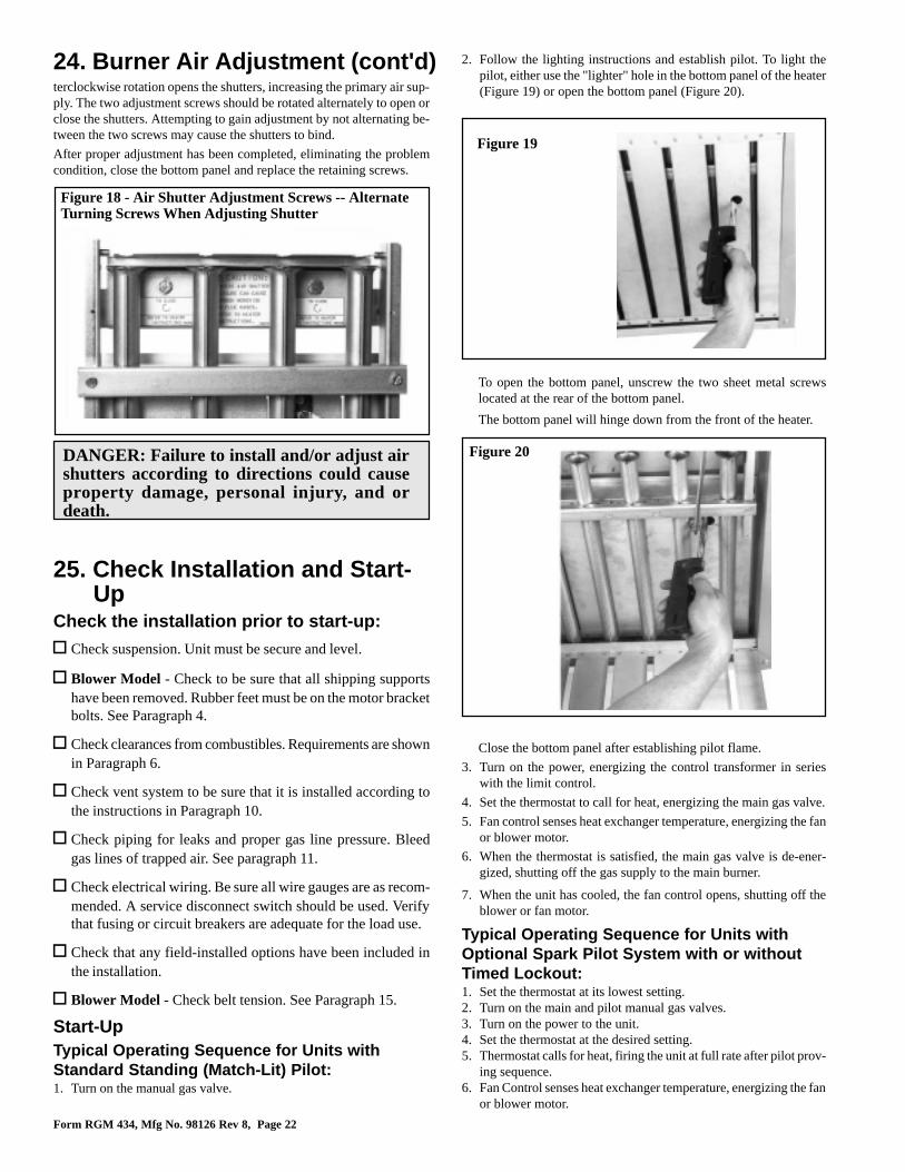
Figure 18 - Air Shutter Adjustment Screws -- AlternateTurning Screws When Adjusting Shutter
Figure 19
24. Burner Air Adjustment (cont'd) 2. Follow the lighting instructions and establish pilot. To light thepilot, either use the "lighter" hole in the bottom panel of the heater(Figure 19) or open the bottom panel (Figure 20).
To open the bottom panel, unscrew the two sheet metal screwslocated at the rear of the bottom panel.
The bottom panel will hinge down from the front of the heater.
Close the bottom panel after establishing pilot flame.
3. Turn on the power, energizing the control transformer in serieswith the limit control.
4. Set the thermostat to call for heat, energizing the main gas valve.
5. Fan control senses heat exchanger temperature, energizing the fanor blower motor.
6. When the thermostat is satisfied, the main gas valve is de-ener-gized, shutting off the gas supply to the main burner.
7. When the unit has cooled, the fan control opens, shutting off theblower or fan motor.
Typical Operating Sequence for Units withOptional Spark Pilot System with or withoutTimed Lockout:1. Set the thermostat at its lowest setting.2. Turn on the main and pilot manual gas valves.3. Turn on the power to the unit.4. Set the thermostat at the desired setting.5. Thermostat calls for heat, firing the unit at full rate after pilot prov-
ing sequence.6. Fan Control senses heat exchanger temperature, energizing the fan
or blower motor.
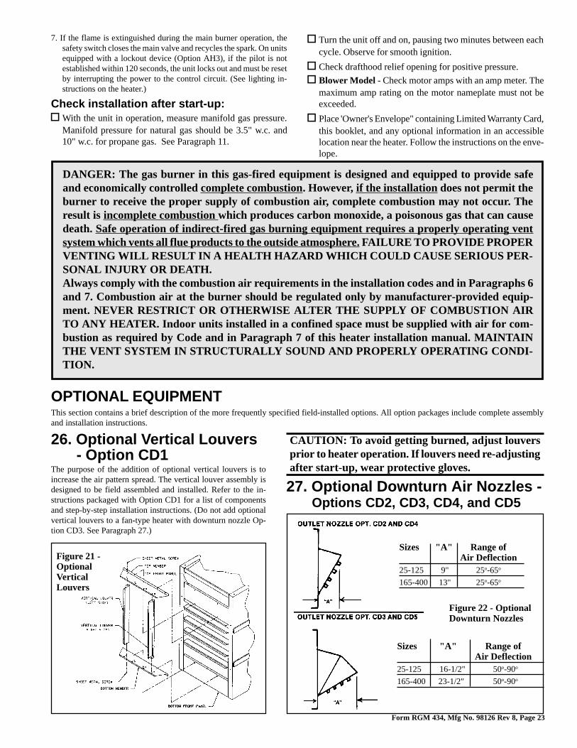
Form RGM 434, Mfg No. 98126 Rev 8, Page 23
DANGER: The gas burner in this gas-fired equipment is designed and equipped to provide safeand economically controlled complete combustion. However, if the installation does not permit theburner to receive the proper supply of combustion air, complete combustion may not occur. Theresult is incomplete combustion which produces carbon monoxide, a poisonous gas that can causedeath. Safe operation of indirect-fired gas burning equipment requires a properly operating ventsystem which vents all flue products to the outside atmosphere. FAILURE TO PROVIDE PROPERVENTING WILL RESULT IN A HEALTH HAZARD WHICH COULD CAUSE SERIOUS PER-SONAL INJURY OR DEATH.Always comply with the combustion air requirements in the installation codes and in Paragraphs 6and 7. Combustion air at the burner should be regulated only by manufacturer-provided equip-ment. NEVER RESTRICT OR OTHERWISE ALTER THE SUPPLY OF COMBUSTION AIRTO ANY HEATER. Indoor units installed in a confined space must be supplied with air for com-bustion as required by Code and in Paragraph 7 of this heater installation manual. MAINTAINTHE VENT SYSTEM IN STRUCTURALLY SOUND AND PROPERLY OPERATING CONDI-TION.
7. If the flame is extinguished during the main burner operation, thesafety switch closes the main valve and recycles the spark. On unitsequipped with a lockout device (Option AH3), if the pilot is notestablished within 120 seconds, the unit locks out and must be resetby interrupting the power to the control circuit. (See lighting in-structions on the heater.)
Check installation after start-up:oWith the unit in operation, measure manifold gas pressure.
Manifold pressure for natural gas should be 3.5" w.c. and10" w.c. for propane gas. See Paragraph 11.
oTurn the unit off and on, pausing two minutes between eachcycle. Observe for smooth ignition.
oCheck drafthood relief opening for positive pressure.
oBlower Model - Check motor amps with an amp meter. Themaximum amp rating on the motor nameplate must not beexceeded.
oPlace 'Owner's Envelope" containing Limited Warranty Card,this booklet, and any optional information in an accessiblelocation near the heater. Follow the instructions on the enve-lope.
OPTIONAL EQUIPMENTThis section contains a brief description of the more frequently specified field-installed options. All option packages include complete assemblyand installation instructions.
Figure 21 -OptionalVerticalLouvers
26. Optional Vertical Louvers- Option CD1
The purpose of the addition of optional vertical louvers is toincrease the air pattern spread. The vertical louver assembly isdesigned to be field assembled and installed. Refer to the in-structions packaged with Option CD1 for a list of componentsand step-by-step installation instructions. (Do not add optionalvertical louvers to a fan-type heater with downturn nozzle Op-tion CD3. See Paragraph 27.)
CAUTION: To avoid getting burned, adjust louversprior to heater operation. If louvers need re-adjustingafter start-up, wear protective gloves.
27. Optional Downturn Air Nozzles -Options CD2, CD3, CD4, and CD5
Sizes "A" Range ofAir Deflection
25-125 9" 25o-65o
165-400 13" 25o-65o
Figure 22 - OptionalDownturn Nozzles
Sizes "A" Range ofAir Deflection
25-125 16-1/2" 50o-90o
165-400 23-1/2" 50o-90o
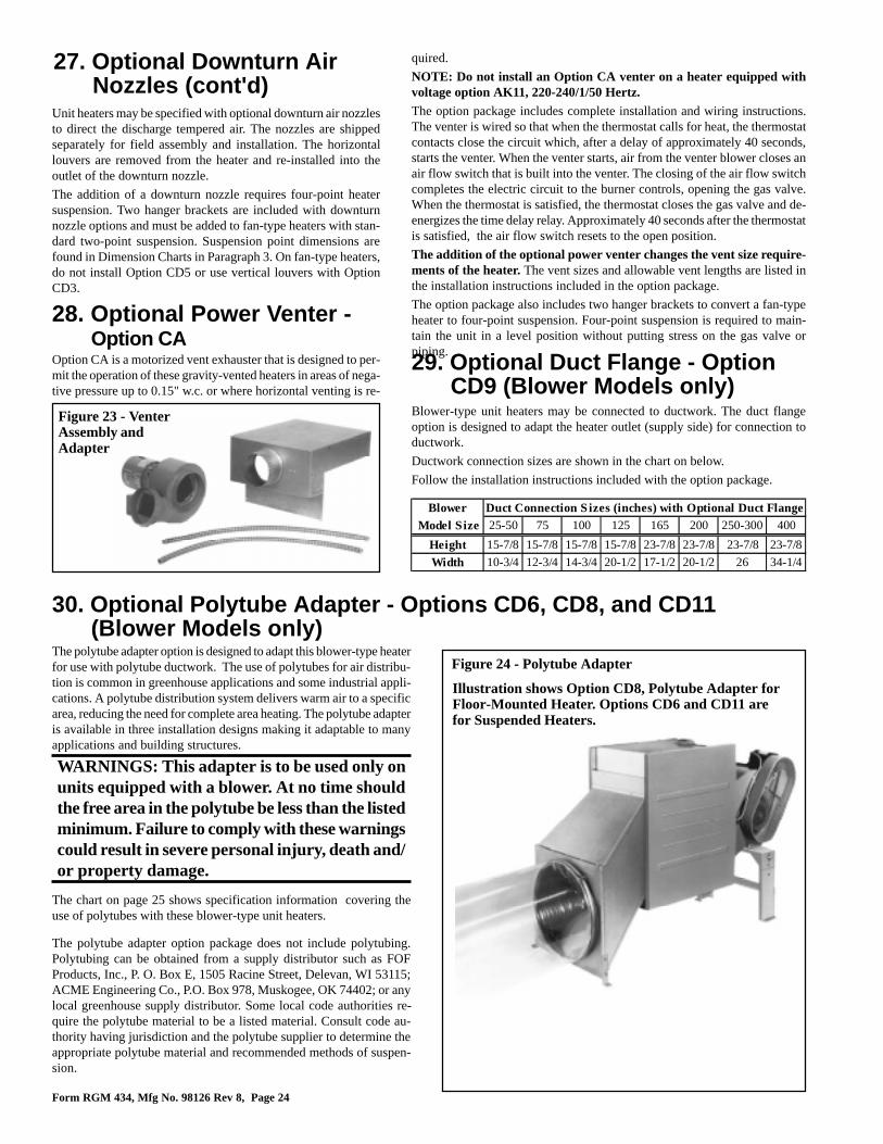
Form RGM 434, Mfg No. 98126 Rev 8, Page 24
30. Optional Polytube Adapter - Options CD6, CD8, and CD11(Blower Models only)
Figure 24 - Polytube Adapter
29. Optional Duct Flange - OptionCD9 (Blower Models only)
Blower-type unit heaters may be connected to ductwork. The duct flangeoption is designed to adapt the heater outlet (supply side) for connection toductwork.
Ductwork connection sizes are shown in the chart on below.
Follow the installation instructions included with the option package.
Illustration shows Option CD8, Polytube Adapter forFloor-Mounted Heater. Options CD6 and CD11 arefor Suspended Heaters.
The chart on page 25 shows specification information covering theuse of polytubes with these blower-type unit heaters.
The polytube adapter option is designed to adapt this blower-type heaterfor use with polytube ductwork. The use of polytubes for air distribu-tion is common in greenhouse applications and some industrial appli-cations. A polytube distribution system delivers warm air to a specificarea, reducing the need for complete area heating. The polytube adapteris available in three installation designs making it adaptable to manyapplications and building structures.
WARNINGS: This adapter is to be used only onunits equipped with a blower. At no time shouldthe free area in the polytube be less than the listedminimum. Failure to comply with these warningscould result in severe personal injury, death and/or property damage.
The polytube adapter option package does not include polytubing.Polytubing can be obtained from a supply distributor such as FOFProducts, Inc., P. O. Box E, 1505 Racine Street, Delevan, WI 53115;ACME Engineering Co., P.O. Box 978, Muskogee, OK 74402; or anylocal greenhouse supply distributor. Some local code authorities re-quire the polytube material to be a listed material. Consult code au-thority having jurisdiction and the polytube supplier to determine theappropriate polytube material and recommended methods of suspen-sion.
Unit heaters may be specified with optional downturn air nozzlesto direct the discharge tempered air. The nozzles are shippedseparately for field assembly and installation. The horizontallouvers are removed from the heater and re-installed into theoutlet of the downturn nozzle.
The addition of a downturn nozzle requires four-point heatersuspension. Two hanger brackets are included with downturnnozzle options and must be added to fan-type heaters with stan-dard two-point suspension. Suspension point dimensions arefound in Dimension Charts in Paragraph 3. On fan-type heaters,do not install Option CD5 or use vertical louvers with OptionCD3.
28. Optional Power Venter -Option CA
Option CA is a motorized vent exhauster that is designed to per-mit the operation of these gravity-vented heaters in areas of nega-tive pressure up to 0.15" w.c. or where horizontal venting is re-
27. Optional Downturn AirNozzles (cont'd)
Figure 23 - VenterAssembly andAdapter
quired.
NOTE: Do not install an Option CA venter on a heater equipped withvoltage option AK11, 220-240/1/50 Hertz.The option package includes complete installation and wiring instructions.The venter is wired so that when the thermostat calls for heat, the thermostatcontacts close the circuit which, after a delay of approximately 40 seconds,starts the venter. When the venter starts, air from the venter blower closes anair flow switch that is built into the venter. The closing of the air flow switchcompletes the electric circuit to the burner controls, opening the gas valve.When the thermostat is satisfied, the thermostat closes the gas valve and de-energizes the time delay relay. Approximately 40 seconds after the thermostatis satisfied, the air flow switch resets to the open position.
The addition of the optional power venter changes the vent size require-ments of the heater. The vent sizes and allowable vent lengths are listed inthe installation instructions included in the option package.
The option package also includes two hanger brackets to convert a fan-typeheater to four-point suspension. Four-point suspension is required to main-tain the unit in a level position without putting stress on the gas valve orpiping.
Blower Duct Connection S izes (inches) with Optional Duct Flange Model Size 25-50 75 100 125 165 200 250-300 400
Height 15-7/8 15-7/8 15-7/8 15-7/8 23-7/8 23-7/8 23-7/8 23-7/8
Width 10-3/4 12-3/4 14-3/4 20-1/2 17-1/2 20-1/2 26 34-1/4
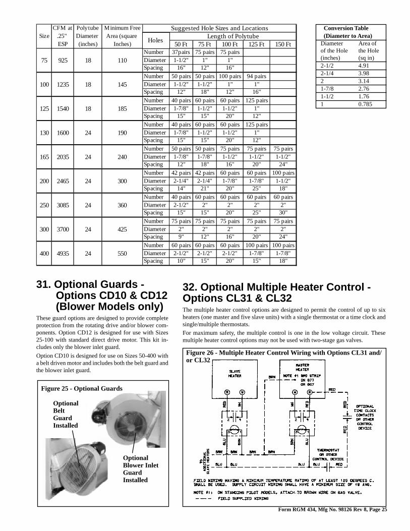
Form RGM 434, Mfg No. 98126 Rev 8, Page 25
Conversion Table(Diameter to Area)
Diameter Area ofof the Hole the Hole(inches) (sq in)2-1/2 4.912-1/4 3.982 3.141-7/8 2.761-1/2 1.761 0.785
31. Optional Guards -Options CD10 & CD12(Blower Models only)
These guard options are designed to provide completeprotection from the rotating drive and/or blower com-ponents. Option CD12 is designed for use with Sizes25-100 with standard direct drive motor. This kit in-cludes only the blower inlet guard.
Option CD10 is designed for use on Sizes 50-400 witha belt driven motor and includes both the belt guard andthe blower inlet guard.
Figure 25 - Optional Guards
OptionalBeltGuardInstalled
OptionalBlower InletGuardInstalled
Figure 26 - Multiple Heater Control Wiring with Options CL31 and/or CL32
32. Optional Multiple Heater Control -Options CL31 & CL32The multiple heater control options are designed to permit the control of up to sixheaters (one master and five slave units) with a single thermostat or a time clock andsingle/multiple thermostats.
For maximum safety, the multiple control is one in the low voltage circuit. Thesemultiple heater control options may not be used with two-stage gas valves.
CFM at Polytube Minimum Free Suggested Hole Sizes and LocationsSize .25" Diameter Area (square Length of Polytube
ESP (inches) Inches) 50 Ft 75 Ft 100 Ft 125 Ft 150 FtNumber 37pairs 75 pairs 75 pairs
75 925 18 110 Diameter 1-1/2" 1" 1"Spacing 16" 12" 16"
Number 50 pairs 50 pairs 100 pairs 94 pairs
100 1235 18 145 Diameter 1-1/2" 1-1/2" 1" 1"Spacing 12" 18" 12" 16"
Number 40 pairs 60 pairs 60 pairs 125 pairs
125 1540 18 185 Diameter 1-7/8" 1-1/2" 1-1/2" 1"Spacing 15" 15" 20" 12"
Number 40 pairs 60 pairs 60 pairs 125 pairs
130 1600 24 190 Diameter 1-7/8" 1-1/2" 1-1/2" 1"Spacing 15" 15" 20" 12"
Number 50 pairs 50 pairs 75 pairs 75 pairs 75 pairs
165 2035 24 240 Diameter 1-7/8" 1-7/8" 1-1/2" 1-1/2" 1-1/2"Spacing 12" 18" 16" 20" 24"
Number 42 pairs 42 pairs 60 pairs 60 pairs 100 pairs
200 2465 24 300 Diameter 2-1/4" 2-1/4" 1-7/8" 1-7/8" 1-1/2"Spacing 14" 21" 20" 25" 18"
Number 40 pairs 60 pairs 60 pairs 60 pairs 60 pairs
250 3085 24 360 Diameter 2-1/2" 2" 2" 2" 2"Spacing 15" 15" 20" 25" 30"
Number 75 pairs 75 pairs 75 pairs 75 pairs 75 pairs
300 3700 24 425 Diameter 2" 2" 2" 2" 2"Spacing 9" 12" 16" 20" 24"
Number 60 pairs 60 pairs 60 pairs 100 pairs 100 pairs
400 4935 24 550 Diameter 2-1/2" 2-1/2" 2-1/2" 1-7/8" 1-7/8"Spacing 10" 15" 20" 15" 18"
Holes
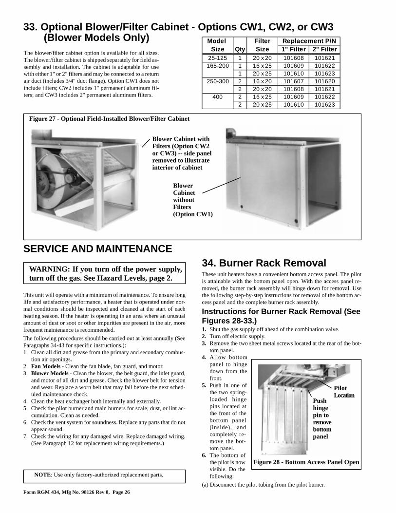
Form RGM 434, Mfg No. 98126 Rev 8, Page 26
SERVICE AND MAINTENANCE
This unit will operate with a minimum of maintenance. To ensure longlife and satisfactory performance, a heater that is operated under nor-mal conditions should be inspected and cleaned at the start of eachheating season. If the heater is operating in an area where an unusualamount of dust or soot or other impurities are present in the air, morefrequent maintenance is recommended.
The following procedures should be carried out at least annually (SeeParagraphs 34-43 for specific instructions.):1. Clean all dirt and grease from the primary and secondary combus-
tion air openings.2. Fan Models - Clean the fan blade, fan guard, and motor.3. Blower Models - Clean the blower, the belt guard, the inlet guard,
and motor of all dirt and grease. Check the blower belt for tensionand wear. Replace a worn belt that may fail before the next sched-uled maintenance check.
4. Clean the heat exchanger both internally and externally.5. Check the pilot burner and main burners for scale, dust, or lint ac-
cumulation. Clean as needed.6. Check the vent system for soundness. Replace any parts that do not
appear sound.7. Check the wiring for any damaged wire. Replace damaged wiring.
(See Paragraph 12 for replacement wiring requirements.)
WARNING: If you turn off the power supply,turn off the gas. See Hazard Levels, page 2.
NOTE: Use only factory-authorized replacement parts.
Figure 28 - Bottom Access Panel Open
Pushhingepin toremovebottompanel
PilotLocation
Figure 27 - Optional Field-Installed Blower/Filter Cabinet
Blower Cabinet withFilters (Option CW2or CW3) -- side panelremoved to illustrateinterior of cabinet
BlowerCabinetwithoutFilters(Option CW1)
33. Optional Blower/Filter Cabinet - Options CW1, CW2, or CW3(Blower Models Only)
The blower/filter cabinet option is available for all sizes.The blower/filter cabinet is shipped separately for field as-sembly and installation. The cabinet is adaptable for usewith either 1" or 2" filters and may be connected to a returnair duct (includes 3/4" duct flange). Option CW1 does notinclude filters; CW2 includes 1" permanent aluminum fil-ters; and CW3 includes 2" permanent aluminum filters.
34. Burner Rack RemovalThese unit heaters have a convenient bottom access panel. The pilotis attainable with the bottom panel open. With the access panel re-moved, the burner rack assembly will hinge down for removal. Usethe following step-by-step instructions for removal of the bottom ac-cess panel and the complete burner rack assembly.
Instructions for Burner Rack Removal (SeeFigures 28-33.)1. Shut the gas supply off ahead of the combination valve.2. Turn off electric supply.3. Remove the two sheet metal screws located at the rear of the bot-
tom panel.4. Allow bottom
panel to hingedown from thefront.
5. Push in one ofthe two spring-loaded hingepins located atthe front of thebottom panel(inside), andcompletely re-move the bot-tom panel.
6. The bottom ofthe pilot is nowvisible. Do thefollowing:
(a) Disconnect the pilot tubing from the pilot burner.
Model Filter Replacement P/NSize Qty Size 1" Filter 2" Filter
25-125 1 20 x 20 101608 101621165-200 1 16 x 25 101609 101622
1 20 x 25 101610 101623250-300 2 16 x 20 101607 101620
2 20 x 20 101608 101621400 2 16 x 25 101609 101622
2 20 x 25 101610 101623
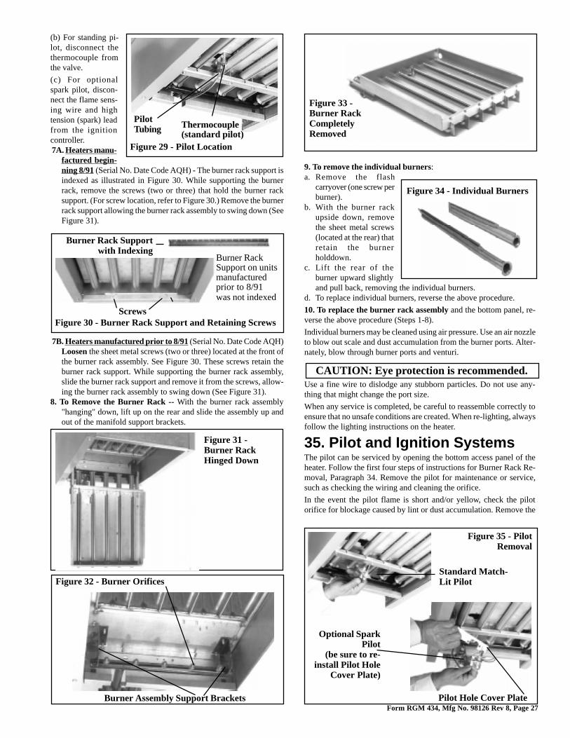
Form RGM 434, Mfg No. 98126 Rev 8, Page 27
(b) For standing pi-lot, disconnect thethermocouple fromthe valve.
(c) For optionalspark pilot, discon-nect the flame sens-ing wire and hightension (spark) leadfrom the ignitioncontroller. 7A. Heaters manu-
factured begin-ning 8/91 (Serial No. Date Code AQH) - The burner rack support isindexed as illustrated in Figure 30. While supporting the burnerrack, remove the screws (two or three) that hold the burner racksupport. (For screw location, refer to Figure 30.) Remove the burnerrack support allowing the burner rack assembly to swing down (SeeFigure 31).
7B. Heaters manufactured prior to 8/91 (Serial No. Date Code AQH)Loosen the sheet metal screws (two or three) located at the front ofthe burner rack assembly. See Figure 30. These screws retain theburner rack support. While supporting the burner rack assembly,slide the burner rack support and remove it from the screws, allow-ing the burner rack assembly to swing down (See Figure 31).
8. To Remove the Burner Rack -- With the burner rack assembly"hanging" down, lift up on the rear and slide the assembly up andout of the manifold support brackets.
Figure 29 - Pilot Location
Thermocouple(standard pilot)
PilotTubing
Figure 31 -Burner RackHinged Down
Burner Rack Supportwith Indexing
Screws
Burner RackSupport on unitsmanufacturedprior to 8/91was not indexed
Figure 30 - Burner Rack Support and Retaining Screws
9. To remove the individual burners:a. Remove the flash
carryover (one screw perburner).
b. With the burner rackupside down, removethe sheet metal screws(located at the rear) thatretain the burnerholddown.
c. Lift the rear of theburner upward slightlyand pull back, removing the individual burners.
d. To replace individual burners, reverse the above procedure.
10. To replace the burner rack assembly and the bottom panel, re-verse the above procedure (Steps 1-8).
Individual burners may be cleaned using air pressure. Use an air nozzleto blow out scale and dust accumulation from the burner ports. Alter-nately, blow through burner ports and venturi.
Use a fine wire to dislodge any stubborn particles. Do not use any-thing that might change the port size.
When any service is completed, be careful to reassemble correctly toensure that no unsafe conditions are created. When re-lighting, alwaysfollow the lighting instructions on the heater.
35. Pilot and Ignition SystemsThe pilot can be serviced by opening the bottom access panel of theheater. Follow the first four steps of instructions for Burner Rack Re-moval, Paragraph 34. Remove the pilot for maintenance or service,such as checking the wiring and cleaning the orifice.
In the event the pilot flame is short and/or yellow, check the pilotorifice for blockage caused by lint or dust accumulation. Remove the
Figure 34 - Individual Burners
CAUTION: Eye protection is recommended.
Figure 33 -Burner RackCompletelyRemoved
Burner Assembly Support Brackets
Figure 32 - Burner Orifices
Pilot Hole Cover Plate
Standard Match-Lit Pilot
Figure 35 - PilotRemoval
Optional SparkPilot
(be sure to re-install Pilot Hole
Cover Plate)
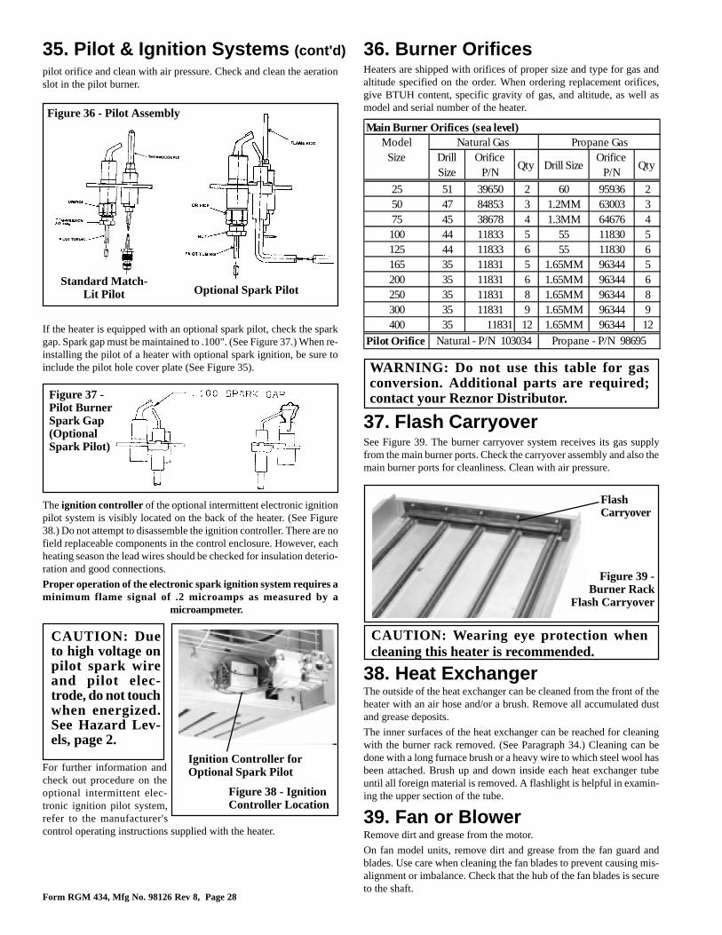
Form RGM 434, Mfg No. 98126 Rev 8, Page 28
37. Flash CarryoverSee Figure 39. The burner carryover system receives its gas supplyfrom the main burner ports. Check the carryover assembly and also themain burner ports for cleanliness. Clean with air pressure.
For further information andcheck out procedure on theoptional intermittent elec-tronic ignition pilot system,refer to the manufacturer'scontrol operating instructions supplied with the heater.
Ignition Controller forOptional Spark Pilot
Figure 38 - IgnitionController Location
CAUTION: Dueto high voltage onpilot spark wireand pilot elec-trode, do not touchwhen energized.See Hazard Lev-els, page 2.
FlashCarryover
Figure 39 -Burner Rack
Flash Carryover
CAUTION: Wearing eye protection whencleaning this heater is recommended.
WARNING: Do not use this table for gasconversion. Additional parts are required;contact your Reznor Distributor.Figure 37 -
Pilot BurnerSpark Gap(OptionalSpark Pilot)
The ignition controller of the optional intermittent electronic ignitionpilot system is visibly located on the back of the heater. (See Figure38.) Do not attempt to disassemble the ignition controller. There are nofield replaceable components in the control enclosure. However, eachheating season the lead wires should be checked for insulation deterio-ration and good connections.
Proper operation of the electronic spark ignition system requires aminimum flame signal of .2 microamps as measured by a
microampmeter.
35. Pilot & Ignition Systems (cont'd)
Figure 36 - Pilot Assembly
Standard Match-Lit Pilot Optional Spark Pilot
pilot orifice and clean with air pressure. Check and clean the aerationslot in the pilot burner.
If the heater is equipped with an optional spark pilot, check the sparkgap. Spark gap must be maintained to .100". (See Figure 37.) When re-installing the pilot of a heater with optional spark ignition, be sure toinclude the pilot hole cover plate (See Figure 35).
36. Burner OrificesHeaters are shipped with orifices of proper size and type for gas andaltitude specified on the order. When ordering replacement orifices,give BTUH content, specific gravity of gas, and altitude, as well asmodel and serial number of the heater.
38. Heat ExchangerThe outside of the heat exchanger can be cleaned from the front of theheater with an air hose and/or a brush. Remove all accumulated dustand grease deposits.
The inner surfaces of the heat exchanger can be reached for cleaningwith the burner rack removed. (See Paragraph 34.) Cleaning can bedone with a long furnace brush or a heavy wire to which steel wool hasbeen attached. Brush up and down inside each heat exchanger tubeuntil all foreign material is removed. A flashlight is helpful in examin-ing the upper section of the tube.
39. Fan or BlowerRemove dirt and grease from the motor.
On fan model units, remove dirt and grease from the fan guard andblades. Use care when cleaning the fan blades to prevent causing mis-alignment or imbalance. Check that the hub of the fan blades is secureto the shaft.
Main Burner Orifices (sea level)Model Natural Gas Propane GasSize Drill
Size Orifice
P/NQty Drill Size
Orifice P/N
Qty
25 51 39650 2 60 95936 250 47 84853 3 1.2MM 63003 375 45 38678 4 1.3MM 64676 4100 44 11833 5 55 11830 5125 44 11833 6 55 11830 6165 35 11831 5 1.65MM 96344 5200 35 11831 6 1.65MM 96344 6250 35 11831 8 1.65MM 96344 8300 35 11831 9 1.65MM 96344 9400 35 11831 12 1.65MM 96344 12
Pilot Orifice Natural - P/N 103034 Propane - P/N 98695
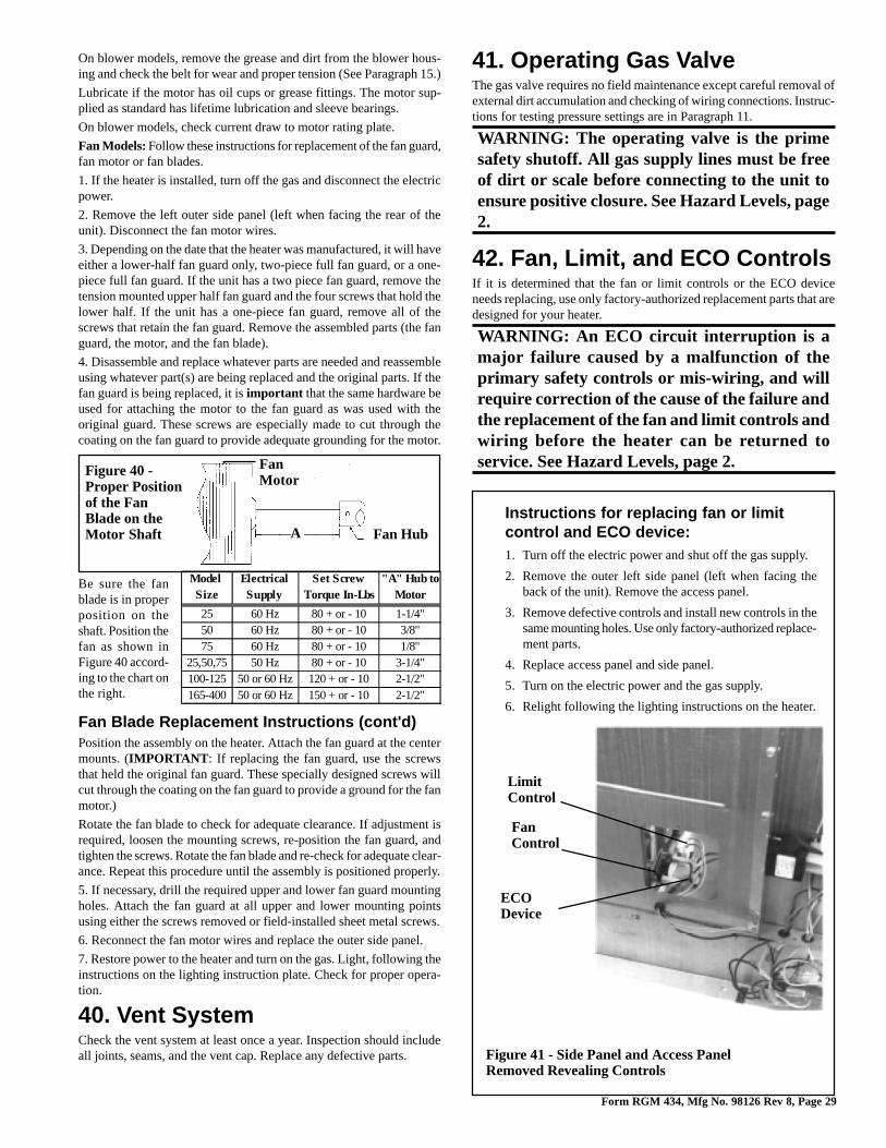
Form RGM 434, Mfg No. 98126 Rev 8, Page 29
Figure 40 -Proper Positionof the FanBlade on theMotor Shaft
Be sure the fanblade is in properposition on theshaft. Position thefan as shown inFigure 40 accord-ing to the chart onthe right.
Fan HubA
FanMotor
On blower models, remove the grease and dirt from the blower hous-ing and check the belt for wear and proper tension (See Paragraph 15.)
Lubricate if the motor has oil cups or grease fittings. The motor sup-plied as standard has lifetime lubrication and sleeve bearings.
On blower models, check current draw to motor rating plate.
Fan Models: Follow these instructions for replacement of the fan guard,fan motor or fan blades.
1. If the heater is installed, turn off the gas and disconnect the electricpower.
2. Remove the left outer side panel (left when facing the rear of theunit). Disconnect the fan motor wires.
3. Depending on the date that the heater was manufactured, it will haveeither a lower-half fan guard only, two-piece full fan guard, or a one-piece full fan guard. If the unit has a two piece fan guard, remove thetension mounted upper half fan guard and the four screws that hold thelower half. If the unit has a one-piece fan guard, remove all of thescrews that retain the fan guard. Remove the assembled parts (the fanguard, the motor, and the fan blade).
4. Disassemble and replace whatever parts are needed and reassembleusing whatever part(s) are being replaced and the original parts. If thefan guard is being replaced, it is important that the same hardware beused for attaching the motor to the fan guard as was used with theoriginal guard. These screws are especially made to cut through thecoating on the fan guard to provide adequate grounding for the motor.
Fan Blade Replacement Instructions (cont'd)Position the assembly on the heater. Attach the fan guard at the centermounts. (IMPORTANT : If replacing the fan guard, use the screwsthat held the original fan guard. These specially designed screws willcut through the coating on the fan guard to provide a ground for the fanmotor.)
Rotate the fan blade to check for adequate clearance. If adjustment isrequired, loosen the mounting screws, re-position the fan guard, andtighten the screws. Rotate the fan blade and re-check for adequate clear-ance. Repeat this procedure until the assembly is positioned properly.
5. If necessary, drill the required upper and lower fan guard mountingholes. Attach the fan guard at all upper and lower mounting pointsusing either the screws removed or field-installed sheet metal screws.
6. Reconnect the fan motor wires and replace the outer side panel.
7. Restore power to the heater and turn on the gas. Light, following theinstructions on the lighting instruction plate. Check for proper opera-tion.
40. Vent SystemCheck the vent system at least once a year. Inspection should includeall joints, seams, and the vent cap. Replace any defective parts.
41. Operating Gas ValveThe gas valve requires no field maintenance except careful removal ofexternal dirt accumulation and checking of wiring connections. Instruc-tions for testing pressure settings are in Paragraph 11.
WARNING: The operating valve is the primesafety shutoff. All gas supply lines must be freeof dirt or scale before connecting to the unit toensure positive closure. See Hazard Levels, page2.
42. Fan, Limit, and ECO ControlsIf it is determined that the fan or limit controls or the ECO deviceneeds replacing, use only factory-authorized replacement parts that aredesigned for your heater.
WARNING: An ECO circuit interruption is amajor failure caused by a malfunction of theprimary safety controls or mis-wiring, and willrequire correction of the cause of the failure andthe replacement of the fan and limit controls andwiring before the heater can be returned toservice. See Hazard Levels, page 2.
Instructions for replacing fan or limitcontrol and ECO device:1. Turn off the electric power and shut off the gas supply.
2. Remove the outer left side panel (left when facing theback of the unit). Remove the access panel.
3. Remove defective controls and install new controls in thesame mounting holes. Use only factory-authorized replace-ment parts.
4. Replace access panel and side panel.
5. Turn on the electric power and the gas supply.
6. Relight following the lighting instructions on the heater.
FanControl
ECODevice
LimitControl
Figure 41 - Side Panel and Access PanelRemoved Revealing Controls
Model Electrical Set Screw "A" Hub toSize Supply Torque In-Lbs Motor
25 60 Hz 80 + or - 10 1-1/4"50 60 Hz 80 + or - 10 3/8"75 60 Hz 80 + or - 10 1/8"
25,50,75 50 Hz 80 + or - 10 3-1/4"100-125 50 or 60 Hz 120 + or - 10 2-1/2"165-400 50 or 60 Hz 150 + or - 10 2-1/2"
Form RGM 434, Mfg No. 98126 Rev 8, Page 30
44. Troubleshooting
43. Blocked Vent SwitchThe manual reset blocked vent switch is located on the front topof the drafthood. The sensor is located near the relief opening ofthe drafthood.
If the blocked vent switch should require replacing, use a fac-tory-authorized replacement switch with the designated tempera-ture setting for the heater.
Blocked Vent Switch
Model Standard Single-Stage
Gas ControlsOptional Two-Stage Gas
ControlsSize Temperature
Setting P/N Temperature
Setting P/N
25 200oF 112751 N/A N/A50 225oF 112752 N/A N/A
100-400 275oF 121275 225oF 112752
TROUBLE PROBABLE CAUSE REMEDYPilot wil l not l ight 1. Pilot cock turned off. 1. Open valve.(match l i t system) 2. Air in gas line. 2. Disconnect pilot line at shutoff. Bleed air from gas supply line.
3. Incorrect lighting procedure. 3. Follow instructions on the heater.4. Dirt in pilot orifice. 4. Remove and clean with compressed air or solvent (do not ream). 5. Extremely high or low gas pressure.5. Check line pressure (See Paragraph 11).6. Bent or kinked pilot tubing. 6. Replace tubing.7. Failed E.C.O. device. 7. Replace E.C.O. device (See Paragraph 42).
Pilot wil l not l ight 1. Manual valve not open. 1. Open manual valve.(spark ignition system)
2. Power not turned on or thermostat not calling for heat.
2. Turn on power. Check fuse/circuit breaker in disconnect switch. If unit is equipped with unit-mounted disconnect switch, check circuit breaker. (See Paragraph 12.) Check thermostat setting.
3. Air in gas line. 3. Bleed gas line.4. Dirt in pilot orifice. 4. Remove and clean with compressed air or solvent (do not ream). 5. Gas pressure too high or too low. 5. Adjust supply pressure. (See Paragraph 11). 6. Kinked pilot tubing. 6. Replace tubing.7. Pilot valve does not open. 7. If 24 volt available at valve, replace valve. 8. No spark: 8. a) Loose wire connections a) Be certain all wires connections are solid.b) Transformer failure. b) Be certain 24 volts is available. c) Incorrect spark gap. c) Maintain spark gap at .100".d) Spark cable shorted to ground. d) Replace worn or grounded spark cable. e) Spark electrode shorted to ground.e) Replace pilot if ceramic spark electrode is cracked or grounded. f) Drafts affecting pilot. f) Make sure all panels are in place and tightly secured to prevent drafts at pilot. g) Ignit ion control not grounded. g) Make certain ignition control is grounded to furnace chassish) Faulty ignit ion controller. h) If 24 volt is available to ignition controller and all other causes have been
eliminated, replace ignit ion control. 9. Optional lockout device interrupting control circuits.
9. Reset lockout devices by interrupting control at thermostat.
10. Activated blocked vent switch. 10. Correct venting problem. Reset switch (See paragraph 19).
Pilot li t but gas valve will not open.
1. Power not turned on or thermostat not calling for heat.
1. Turn on power. Check fuse/circuit breaker in disconnect switch. If unit is equipped with unit-mounted disconnect switch, check circuit breaker. (See Paragraph 12.) Turn up thermostat.
(All manual valves 2. Circuit to magnetic valve open. 2. Check wiring and connections at transformer and thermostat.
are open) (Match 3. Faulty transformer. 3. Replace transformer.l it system) 4. Faulty or dirty thermocouple or
safety pilot switch, or failed E.C.O. device.
4. Clean and test with millivolt meter or test kit. Replace defective part.
5. Faulty thermostat (See manufacturer's instructions.)
5. Replace thermostat.
6. Faulty magnetic valve. 6. Replace valve or magnetic head.7. High gas pressure. 7. Maximum gas pressure 8 oz. or 14" w.c. (See Paragraph 11).8. Activated blocked vent switch. 8. Correct venting problem. Reset switch. (See Paragraph 19.)
Form RGM 434, Mfg No. 98126 Rev 8, Page 31
TROUBLE (cont'd) PROBABLE CAUSE (cont'd) REMEDY (cont'd)Pilot l ights, main 1. Manual valve not open. 1. Open manual valve.valve wil l not open 2. Main valve not operating. 2.(Spark Ignition system)
a) Defective valve. a) If 24 volt is measured at valve connections and valve remains closed, replace valve.
b) Loose wire connections. b) Check and tighten all wiring connections.3. Ignit ion control does not power main valve.
3.
a) Loose wire connections. a) Check and tighten all wiring connections.b) Flame sensor grounded. (Pilot lights - spark continues)
b) Be certain flame sensor lead is not grounded or insulation or ceramic is not cracked. Replace as required.
c) Gas pressure incorrect. c) Set supply pressure at 5" w.c. to 14" w.c. for natural gas and 11" w.c. to 14" w.c. for propane gas.
d) Cracked ceramic at sensor. d) Replace sensor.e) Faulty ignit ion controller. e) See Paragraph 34. If all checks indicate no other cause, replace ignit ion
controller. DO NOT ATTEMPT TO REPAIR IGNITION CONTROLLER. THIS DEVICE HAS NO FIELD REPLACEABLE PARTS.
No heat (Heater Operating)
1. Incorrect manifold pressure or orifices. 1. Check manifold pressure (See Paragraph 11).
2. Cycling on limit control. 2.Check air throughput (See Paragraph 16). 3. Improper thermostat location or adjustment.
3. See thermostat manufacturer's instructions.
Cold air delivered 1. Fan control improperly wired 1. Connect as per wiring diagram. On Start-up 2. Defective fan control. 2. Replace fan control. During Operation 3. Incorrect manifold pressure. 3. Check manifold line pressure (See Paragraph 11).Motor wil l not run 1. Circuit open. 1. Check wiring and connections. .
2. Fan control inoperative. 2. Replace fan control. 3. Defective motor or capacitor. 3. Replace motor or capacitor.
Motor turns on 1. Fan control improperly wired. 1. Connect as per wiring diagram.and off while 2. Defective fan control. 2. Replace fan control.burner is operating 3. Poor contact between fan control and heat
exchanger tube. Surface contact is required. 3. Check for bent mounting or loose mounting screws.
(See Motor cuts out 4. Motor overload device cycling on and off. 4. Check motor load against motor rating plate. Replace motor if needed. on overload below) 5. Low ambient temperature (less than 40oF)
causing false cycling. 5. Install fan delay relay kit (See Paragraph 18.)
Fan motor cuts 1. Low or high voltage supply . 1. Correct electric supply.out on overload 2. Defective motor. 2. Replace motor.
3. Poor air flow. 3. Clean motor, fan and fan guard. 4. Defective bearing or lubrication. 4. Lubricate bearings or replace motor.
Blower motor cuts 1. Improper motor pulley and/or adjustment. 1. See instructions in Paragraph 16. out on overload 2. Improper static pressure in the duct system. 2. Adjust duct system dampers.
3. Low voltage. 3. Check power supply.
Form RGM 434, Mfg No. 98126 Rev 8, Page 32
©1999 Thomas & Betts Corporation, All rights reserved. Printed in the U.S.A.
MANUFACTURER OF GAS, OIL, ELECTRIC HEATING AND VENTILATING SYSTEMS
Trademark Note: Reznor® is registered in the United States and other countries. All other trademarks arethe property of their respective organizations.
8/99 3M WE Form 434 (Version A.8)
FIRST: Contact the installer.
Name _______________________________________________________________________________________
Address ________________________________________________________________________________________
________________________________________________________________________________________
________________________________________________________________________________________
Phone ________________________________________________________________________________________
SECOND: Contact the nearest distributor (See telephone Yellow Pages.)
THIRD: Contact: REZNOR®/ Thomas & Betts Corporation
150 McKinley Avenue
Mercer, PA 16137
Phone: (724) 662-4400
Model No. ______________________________________________________________________________________________
Unit Serial No. __________________________________________________________________________________________
Date of Installation _______________________________________________________________________________________
FOR SERVICE OR REPAIR, FOLLOW THESE STEPS IN ORDER: