g200, g400, and g600 - cole-parmer...g200, g400, and g600 laboratory hydrogen generators...
TRANSCRIPT
PD-0100-0074
Revision A
G200, G400, and G600 LABORATORY HYDROGEN GAS
GENERATORS
Installation, Operation & Maintenance Manual
G200, G400, and G600 Laboratory Hydrogen Generators
Installation, Operation & Maintenance Manual
PD-0100-0074 Rev. A --UNAUTHORIZED COPIES PROHIBITED-- Page 2 of 57
G200, G400, and G600 Laboratory Hydrogen Generators Installation
Operation & Maintenance Manual Covering the following laboratory hydrogen generator models:
Model
Hydrogen G200 Hydrogen G400 Hydrogen G600
Proton OnSite
10 Technology Drive Wallingford, CT 06492
203-949-8697 203-678-2000
[email protected] www.protononsite.com
© 2013 Proton Energy Systems, Inc. d/b/a Proton OnSite
All rights not expressly granted herein are reserved.
Information in this document is provided in connection with Proton Energy Systems Inc. d/b/a Proton OnSite (“Proton”) products and services. No license, express or implied, by estoppel or otherwise, to any intellectual property rights is granted by this document. Except as provided in Proton Terms and Conditions of Sale for such products and services, Proton assumes no liability whatsoever, and Proton disclaims any express or implied warranty, whether written or oral, relating to sale and/or use of Proton products or services including liability or warranties relating to fitness for a particular purpose, merchantability, or infringement of any patent, copyright or other intellectual property right. Proton products are not intended for use in medical, life saving, or life sustaining applications.
Proton may make changes to specifications and product descriptions at any time, without notice.
This document as well as any software, processes or procedures described in it is furnished under license and may only be used or copied in accordance with the terms of the license. The information in this document is furnished for informational use only, is subject to change without notice, and should not be construed as a commitment by Proton. Proton assumes no responsibility or liability for any errors or inaccuracies that may appear in this document or any software that may be provided in association with this document.
Except as permitted by such license, no part of this document may be reproduced, stored in a retrieval system, or transmitted in any form or by any means without the express written consent of Proton.
® Proton, Proton OnSite, Proton Energy Systems, the Proton design, StableFlow, StableFlow Hydrogen Control System and design, HOGEN, and FuelGen are trademarks of Proton Energy Systems, Inc.
Any other brands and/or names used herein are the property of their respective owners.
G200, G400, and G600 Laboratory Hydrogen Generators
Installation, Operation & Maintenance Manual
PD-0100-0074 Rev. A --UNAUTHORIZED COPIES PROHIBITED-- Page 3 of 57
Disclaimer Proton OnSite has written this manual to be an easy to use guide for the G200/G400/G600 Hydrogen Gas Generators. All statements, technical information, and recommendations in this manual and in any guides or related documents are believed reliable, but the accuracy and completeness thereof are not guaranteed or warranted. They are not intended to be, nor should they be understood to be, representations or warranties concerning the products described.
This hydrogen gas generator has been sold subject to the limited warranties set forth in the warranty statement. Further, Proton reserves the right to make changes in the specifications of the products described in this manual at any time without notice and without obligation to notify any person of such changes.
This laboratory hydrogen generator is designed for operation only by trained personnel familiar with the use of similar equipment and with safety requirements for the use of hydrogen and other industrial gases. Before operating this laboratory hydrogen generator, make sure to read and understand this information provided herein. If you have questions, please contact Proton OnSite Systems or your generator supplier.
G200, G400, and G600 Laboratory Hydrogen Generators
Installation, Operation & Maintenance Manual
PD-0100-0074 Rev. A --UNAUTHORIZED COPIES PROHIBITED-- Page 4 of 57
LIMITED WARRANTY
HYDROGEN GAS GENERATOR SYSTEMS
LIMITED WARRANTY: PROTON ENERGY SYSTEMS INC. (“PROTON”) warrants that the ITEMS LISTED BELOW shall be free from defects in material and workmanship for the stated period of time commencing from date of shipment or as stated below.
HYDROGEN GAS GENERATOR SYSTEMS: Two (2) years from shipment
Repair or replacement parts for Hydrogen Gas Generator System: Ninety (90) days from shipment
EXCLUDED FROM THIS LIMITED WARRANTY: The following shall be excluded from the Limited Warranty:
• Parts and items considered consumable in normal operations, including those parts and items supplied with the Hydrogen Gas Generator System (“System”) for maintenance.
• Any System and its parts that are not installed, operated, and maintained in accordance with the unit’s manual supplied with the System.
• Damages due to accident, abuse, acts of God, acts of terrorism, misuse or negligence, or which result, in whole or in part, from improper or unauthorized use or repair of the System, or use of the System in a manner for which it was not designed, or by causes external to the System such as, but not limited to, power or air conditioning failure or voltage irregularities.
REMEDY: BUYER’S sole and exclusive remedy in the event of defect, and the liability of PROTON hereunder is limited to the adjustment, repair, or replacement of the defective item or part with a similar item or part free of defect.
Such adjustments, repairs, or replacements will be made at PROTON’S Wallingford, Connecticut, plant or, for Systems only, at the site of the System, if BUYER so elects. All costs for shipping equipment or parts shall be on the account of the BUYER whether to or from the point of manufacture. Labor costs associated with travel, expenses, and subsistence costs for field services shall be on the account of the BUYER.
VOIDING OF THE LIMITED WARRANTY: This Limited Warranty is immediately void upon:
• THE OPENING OR DISASSEMBLY OF THE SYSTEM CABINET (OR ANY PART THEREIN), OR
• THE SALE, ASSIGNMENT OR ANY OTHER TRANSFER OF TITLE BY BUYER OF THE ITEMS OR PARTS OTHERWISE COVERED UNDER THIS LIMITED WARRANTY
WAIVER OF ALL OTHER WARRANTIES: THE LIMITED WARRANTY PROVIDED HEREUNDER AND THE RIGHTS AND REMEDIES OF THE BUYER HEREUNDER ARE IN LIEU OF, AND BUYER EXPRESSLY WAIVES, ALL OTHER WARRANTIES, GUARANTEES, OBLIGATIONS, LIABILITIES, OR REMEDIES, EXPRESSED OR IMPLIED, ARISING BY LAW OR OTHERWISE, INCLUDING WITHOUT LIMITATION IMPLIED WARRANTIES OF MERCHANTABILITY AND NON-INFRINGEMENT, IMPLIED WARRANTIES ARISING FORM THE COURSE OF DEALING OR USAGE OF TRADE AND IMPLIED WARRANTIES OF SUITABILITY OR FITNESS FOR A PARTICULAR PURPOSE.
LIMITATION OF LIABILITY: THE REMEDIES PROVIDED IN THIS LIMITED WARRANTY ARE EXCLUSIVE AND PROTON SHALL IN NO WAY BE LIABLE FOR INCIDENTAL OR CONSEQUENTIAL DAMAGES OF ANY KIND WHATSOEVER INCLUDING WITHOUT LIMITATION LOSS OF USE, REVENUE OR PROFIT.
G200, G400, and G600 Laboratory Hydrogen Generators
Installation, Operation & Maintenance Manual
PD-0100-0074 Rev. A --UNAUTHORIZED COPIES PROHIBITED-- Page 5 of 57
G200, G400, and G600 Laboratory Hydrogen Generators
INSTALLATION, OPERATION & MAINTENANCE MANUAL
Prepared by
PROTON ONSITE®
CONTENTS
1 Introduction ................................................................................................................ 10
1.1 General Information..................................................................................................... 11
1.2 Product Specifications .................................................................................................. 13
2 Safety .......................................................................................................................... 17
2.1 Using Hydrogen Gas ..................................................................................................... 17
2.2 Safety Devices ............................................................................................................... 18
2.3 Technical Service Contact Information ....................................................................... 18
3 Placement ................................................................................................................... 19
3.1 Unpacking the Generator ............................................................................................. 19
3.2 Positioning the Generator ............................................................................................ 20
4 Installation Procedure ................................................................................................ 24
4.1 Mechanical Setup ......................................................................................................... 24
4.2 Electrical Setup ............................................................................................................. 25
4.3 Before Using the Generator for the First Time ........................................................... 25
5 Operation .................................................................................................................... 27
5.1 Startup—System Operation or Interface..................................................................... 27
5.2 Steady State Operation ................................................................................................. 29
5.3 Standby Mode ............................................................................................................... 30
5.4 Selecting the Units Displayed ....................................................................................... 30
5.5 Shutdown ...................................................................................................................... 31
5.6 Alarm Contact Output ................................................................................................. 32
5.7 Desiccant Timer ............................................................................................................ 33
5.8 Additional Information Screens ................................................................................... 34 5.8.1 Alarms and Warnings ............................................................................................................. 34 5.8.2 Input Output Status ................................................................................................................. 35 5.8.3 Engineering and Parameter Config. ......................................................................................... 35
G200, G400, and G600 Laboratory Hydrogen Generators
Installation, Operation & Maintenance Manual
PD-0100-0074 Rev. A --UNAUTHORIZED COPIES PROHIBITED-- Page 6 of 57
6 Customer Configuration ............................................................................................. 36
6.1 Auto-Fill ........................................................................................................................ 36
7 Maintenance ............................................................................................................... 38
7.1 Maintenance Schedule .................................................................................................. 38
7.2 Ion-Exchange Resin Bag............................................................................................... 39
7.3 Water Quality ............................................................................................................... 41
7.4 Desiccant Replacement ................................................................................................. 42
7.5 Circulating Pump Replacement ................................................................................... 45
7.6 Associated Spare Parts and Components .................................................................... 47
7.7 Cleaning the Generator ................................................................................................ 47
8 Troubleshooting .......................................................................................................... 48
8.1 Leak Detection .............................................................................................................. 48
8.2 Replacing DI Water ...................................................................................................... 49
8.3 Error and Warning Codes at Startup or Operation.................................................... 50
9 Frequently Asked Questions ....................................................................................... 52
10 APPENDIX A—FORMS ............................................................................................ 54
10.1 Ion-Exchange Resin Bag Change-Log ......................................................................... 54
10.2 Customer Registration Form ....................................................................................... 55
G200, G400, and G600 Laboratory Hydrogen Generators
Installation, Operation & Maintenance Manual
PD-0100-0074 Rev. A --UNAUTHORIZED COPIES PROHIBITED-- Page 7 of 57
TABLE OF FIGURES FIGURE 1: SERIAL NUMBER IDENTIFICATION PLATE ........................................................................................... 12 FIGURE 2: CABINET DIMENSIONS ..................................................................................................................... 15 FIGURE 3: LIFTING GENERATOR OUT OF SHIPPING BOX ..................................................................................... 19 FIGURE 4: FRONT VIEW OF HYDROGEN GENERATOR .......................................................................................... 21 FIGURE 5: HYDROGEN GENERATOR—RECOMMENDED CLEARANCES ................................................................... 22 FIGURE 6: HYDROGEN GENERATOR—BACK VIEW .............................................................................................. 22 FIGURE 7: HYDROGEN GENERATOR—ANGLED VIEW .......................................................................................... 23 FIGURE 8: G200, G400, OR G600 HYDROGEN CONNECTIONS ............................................................................. 24 FIGURE 9 POWER CORD CONNECTION .............................................................................................................. 25 FIGURE 10: WATER-DRAIN FITTING .................................................................................................................. 26 FIGURE 11 ION-EXCHANGE RESIN BAG ............................................................................................................. 26 FIGURE 12: POWER-UP SWITCH ....................................................................................................................... 27 FIGURE 13: SYSTEM BOOT UP SCREEN .............................................................................................................. 27 FIGURE 14: MAIN OPERATING SCREEN ............................................................................................................. 28 FIGURE 15: PRESSURE SET-POINT .................................................................................................................... 28 FIGURE 16: KEYPAD........................................................................................................................................ 28 FIGURE 17: PRESSURIZING SYSTEM................................................................................................................... 28 FIGURE 18: OPEN OUTPUT BUTTON .............................................................................................................. 29 FIGURE 19: CLOSE OUTPUT BUTTON............................................................................................................ 29 FIGURE 20: PSIG SCREEN ................................................................................................................................ 30 FIGURE 21: MANUAL SHUTDOWN ..................................................................................................................... 31 FIGURE 22: ALARM OUTPUT CONTACTS ............................................................................................................ 32 FIGURE 23: W04 REPLACE DESICCANT WARNING .............................................................................................. 33 FIGURE 24: SCREEN SELECT ............................................................................................................................ 33 FIGURE 25: DESICCANT TIMER ......................................................................................................................... 33 FIGURE 26: ACTIVE ALARM SCREEN.................................................................................................................. 34 FIGURE 27: WARNING SCREEN ......................................................................................................................... 34 FIGURE 28: ALARM HISTORY SCREEN ................................................................................................................ 34 FIGURE 29: SELECT IO STATUS ........................................................................................................................ 35 FIGURE 30: DISCRETE INPUT STATUS SCREEN ................................................................................................... 35 FIGURE 31: DISCRETE OUTPUT STATUS SCREEN ................................................................................................ 35 FIGURE 32: ANALOG INPUT STATUS SCREEN ...................................................................................................... 35 FIGURE 33: ANALOG OUTPUT STATUS SCREEN .................................................................................................. 35 FIGURE 34: CUSTOMER CONFIG. ...................................................................................................................... 36 FIGURE 35 RESIN BAG REMOVAL ...................................................................................................................... 40 FIGURE 36 RESIN BAG ASSEMBLY ..................................................................................................................... 40 FIGURE 37 DESICCANT CARTRIDGE .................................................................................................................. 42 FIGURE 38 DESICCANT CARTRIDGE DISASSEMBLY .............................................................................................. 43 FIGURE 39 DESICCANT LEVEL .......................................................................................................................... 43 FIGURE 40 CIRCULATING PUMP CONNECTOR AND MOUNTING SCREWS. ................................................................ 45 FIGURE 41 CIRCULATING PUMP LOCATION ....................................................................................................... 46 FIGURE 42: SYSTEM LEAK WARNING ................................................................................................................. 48 FIGURE 43: PRODUCT LEAK WARNING .............................................................................................................. 48
G200, G400, and G600 Laboratory Hydrogen Generators
Installation, Operation & Maintenance Manual
PD-0100-0074 Rev. A --UNAUTHORIZED COPIES PROHIBITED-- Page 8 of 57
LIST OF TABLES TABLE 1: TECHNICAL SPECIFICATIONS FOR THE G200/G400/G600 HYDROGEN GENERATORS ............................... 14 TABLE 2: GENERATOR GAS AND ELECTRICAL INLET/OUTLET CONNECTIONS ......................................................... 16 TABLE 3: MAINTENANCE SCHEDULE ................................................................................................................. 38 TABLE 4: PARTS LIST ....................................................................................................................................... 47 TABLE 5: LEAK INDICATORS ............................................................................................................................. 49 TABLE 6: ERROR CODES .................................................................................................................................. 51
G200, G400, and G600 Laboratory Hydrogen Generators
Installation, Operation & Maintenance Manual
PD-0100-0074 Rev. A --UNAUTHORIZED COPIES PROHIBITED-- Page 9 of 57
This Installation, Operation & Maintenance Manual of the Hydrogen Generator uses the following safety symbols and conventions to alert you to information intended to help you operate your laboratory hydrogen generators correctly and safely.
Manual Conventions
—INDICATES A POTENTIALLY HAZARDOUS SITUATION, WHICH, IF NOT AVOIDED, COULD RESULT IN DEATH OR SERIOUS INJURY. THE READER IS IN A SITUATION WHICH COULD CAUSE BODILY INJURY. DO NOT PROCEED BEYOND A WARNING SYMBOL UNTIL THE INDICATED CONDITIONS ARE FULLY UNDERSTOOD AND MET.
—Indicates a potentially hazardous situation, which, if not avoided, may result in minor or moderate injury. It may also be used to alert against unsafe practices. This could result in equipment damage or loss of data. Do not proceed beyond a Caution symbol until the indicated conditions are fully understood and met.
—Notes contain helpful suggestions or references.
G200, G400, and G600 Laboratory Hydrogen Generators
Installation, Operation & Maintenance Manual
PD-0100-0074 Rev. A --UNAUTHORIZED COPIES PROHIBITED-- Page 10 of 57
1 Introduction
Congratulations on your purchase of a G200, G400, or G600 hydrogen generator, the most capable family of laboratory hydrogen generator products available today. The ultimate cylinder alternatives, the G200, G400, and G600 laboratory hydrogen generators provide ultra high purity-grade hydrogen on demand, combining caustic-free PEM electrolysis technology with an easy to refill desiccant bed cartridge. Proton OnSite’s hydrogen generators provide high purity-grade hydrogen on demand and provide the following benefits:
• Up to 600 cc/min flow rate
• Up to 8 barg (116 psig) delivery pressure
• Stable gas costs
• Reduced likelihood of contamination from cylinder change-out
• Elimination of cylinder upkeep
• No caustic or other hazardous materials
• Narrow footprint for enhanced laboratory space utilization
• Standard de-ionized (DI) water auto-fill or simple manual DI fill with removable DI tank
• User-friendly electronic control panel with both English and Metric units
• Report alarms
• Touch Screen Display
Proton OnSite has provided these instructions to guide in the installation, operation, and maintenance of the hydrogen generator. These instructions provide technical product information, installation requirements, and detailed mechanical interface specifications. Important safety information is also included in this manual. Please take time to familiarize yourself with the system and the manual.
This manual attempts to answer most of the frequently asked questions with regards to the operation of the unit. However, should you have any questions, the Proton OnSite technical staff stands ready to answer them and support the successful deployment of this equipment. Please call (203) 949-8697 and ask for field service technical support or email [email protected]. Please have the part number and configuration number of your unit available.
IT IS THE CUSTOMER’S RESPONSIBILITY TO CONSULT WITH THE LOCAL AUTHORITY HAVING JURISDICTION (AHJ) REGARDING LOCAL CODE REQUIREMENTS FOR INSTALLATION AND OPERATION OF THIS EQUIPMENT.
G200, G400, and G600 Laboratory Hydrogen Generators
Installation, Operation & Maintenance Manual
PD-0100-0074 Rev. A --UNAUTHORIZED COPIES PROHIBITED-- Page 11 of 57
DO NOT USE THE LABORATORY HYDROGEN GENERATOR IN A MANNER NOT SPECIFIED BY PROTON ONSITE.
Proton Onsite can offer a full range of installation services if you are not comfortable with installation of the hydrogen generator.
There are no user serviceable parts inside the laboratory hydrogen generator. Any interference with the internal parts voids the manufacturer’s warranty.
1.1 General Information
The G-Series laboratory hydrogen generator, when connected to a suitable AC power source and fed with a suitable quality of DI (de-ionized) water, produces a continuous stream of pressurized ultra high-purity (UHP) hydrogen gas and automatically maintains a user-selected, downstream pressure.
This manual covers installing, operating, and maintaining the Hydrogen Generator. The manual assumes the user is familiar with pneumatic circuit components, and is aware of appropriate safety precautions and using compressed air and hydrogen gases.
The G200, G400, or G600 hydrogen generator, available in 200, 400, or 600 cc/min hydrogen production capabilities, is suitable for use in laboratories and light industrial environments, and is non-hazardous for transporting.
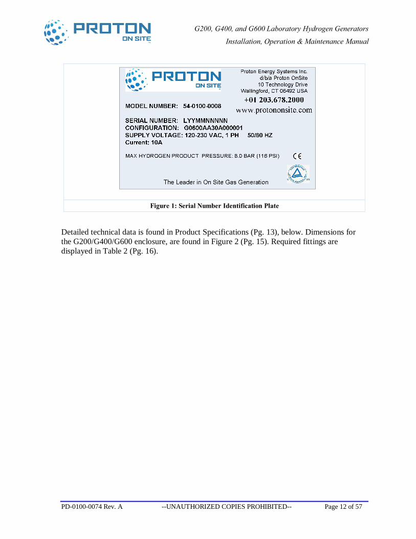
The G200, G400, or G600 hydrogen generator should be installed and running within six months of shipment from the manufacturer. An example of the serial number identification plate, attached to the back of the G200, G400, or G600 hydrogen generator, is shown in Figure 1. The serial number contains an embedded date code, which is the date of system manufacture. Manufacture date is formatted as “mm/yy.” If the manufacture date code is more than six months before the startup date of your system, please contact Proton OnSite for instructions.
G200, G400, and G600 Laboratory Hydrogen Generators
Installation, Operation & Maintenance Manual
PD-0100-0074 Rev. A --UNAUTHORIZED COPIES PROHIBITED-- Page 12 of 57
Figure 1: Serial Number Identification Plate
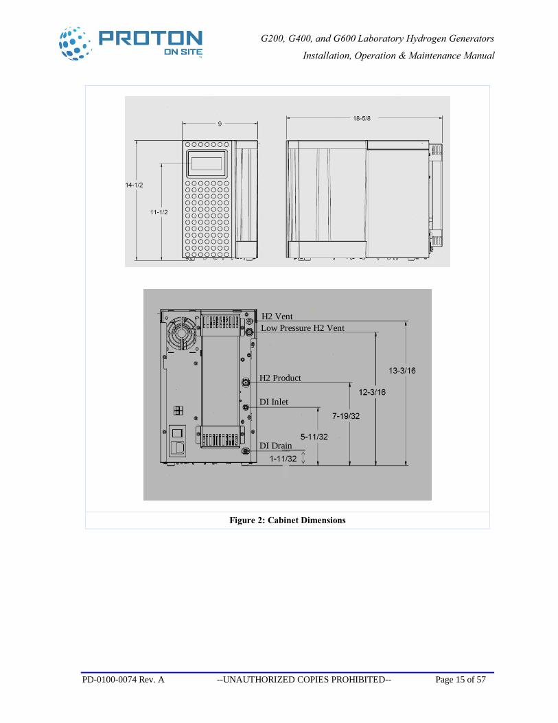
Detailed technical data is found in Product Specifications (Pg. 13), below. Dimensions for the G200/G400/G600 enclosure, are found in Figure 2 (Pg. 15). Required fittings are displayed in Table 2 (Pg. 16).
G200, G400, and G600 Laboratory Hydrogen Generators
Installation, Operation & Maintenance Manual
PD-0100-0074 Rev. A --UNAUTHORIZED COPIES PROHIBITED-- Page 13 of 57
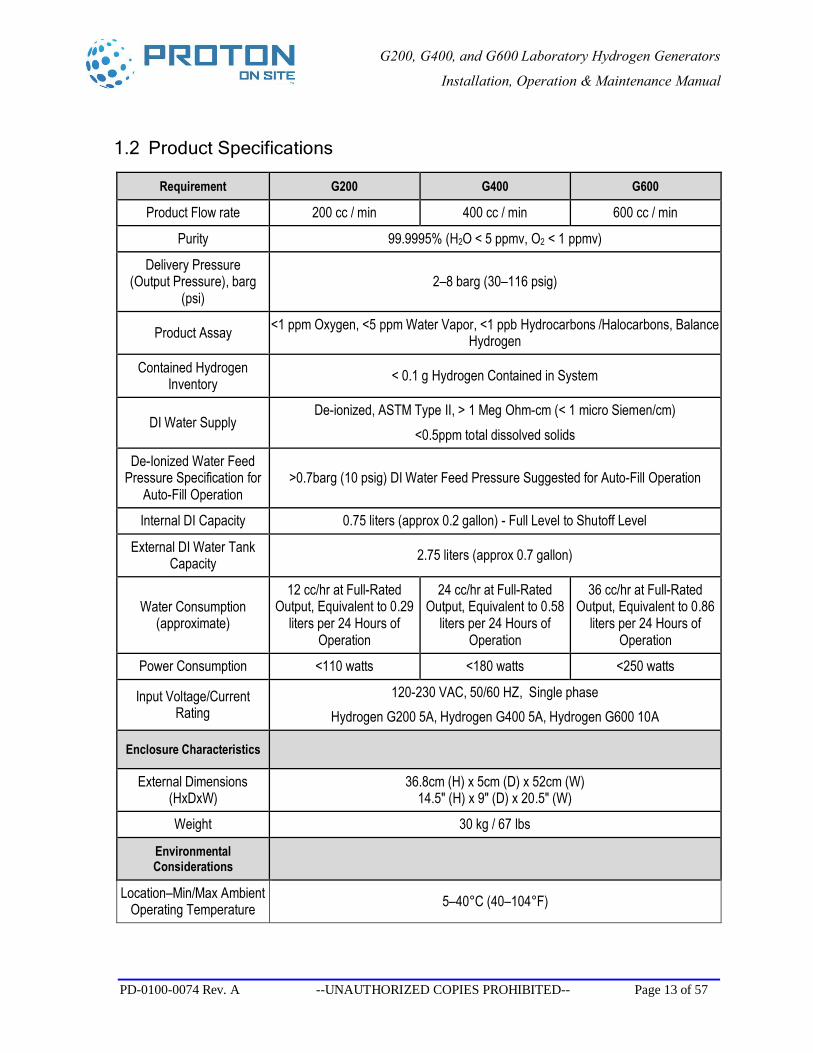
1.2 Product Specifications
Requirement G200 G400 G600
Product Flow rate 200 cc / min 400 cc / min 600 cc / min
Purity 99.9995% (H2O < 5 ppmv, O2 < 1 ppmv)
Delivery Pressure (Output Pressure), barg
(psi) 2–8 barg (30–116 psig)
Product Assay <1 ppm Oxygen, <5 ppm Water Vapor, <1 ppb Hydrocarbons /Halocarbons, Balance Hydrogen
Contained Hydrogen Inventory < 0.1 g Hydrogen Contained in System
DI Water Supply De-ionized, ASTM Type II, > 1 Meg Ohm-cm (< 1 micro Siemen/cm)
<0.5ppm total dissolved solids
De-Ionized Water Feed Pressure Specification for
Auto-Fill Operation >0.7barg (10 psig) DI Water Feed Pressure Suggested for Auto-Fill Operation
Internal DI Capacity 0.75 liters (approx 0.2 gallon) - Full Level to Shutoff Level
External DI Water Tank Capacity 2.75 liters (approx 0.7 gallon)
Water Consumption (approximate)
12 cc/hr at Full-Rated Output, Equivalent to 0.29
liters per 24 Hours of Operation
24 cc/hr at Full-Rated Output, Equivalent to 0.58
liters per 24 Hours of Operation
36 cc/hr at Full-Rated Output, Equivalent to 0.86
liters per 24 Hours of Operation
Power Consumption <110 watts <180 watts <250 watts
Input Voltage/Current Rating
120-230 VAC, 50/60 HZ, Single phase Hydrogen G200 5A, Hydrogen G400 5A, Hydrogen G600 10A
Enclosure Characteristics
External Dimensions (HxDxW)
36.8cm (H) x 5cm (D) x 52cm (W) 14.5" (H) x 9" (D) x 20.5" (W)
Weight 30 kg / 67 lbs
Environmental Considerations
Location–Min/Max Ambient Operating Temperature 5–40°C (40–104°F)
G200, G400, and G600 Laboratory Hydrogen Generators
Installation, Operation & Maintenance Manual
PD-0100-0074 Rev. A --UNAUTHORIZED COPIES PROHIBITED-- Page 14 of 57
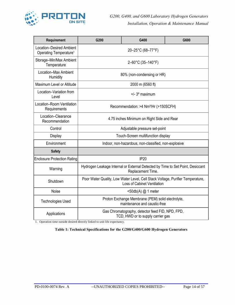
Requirement G200 G400 G600
Location–Desired Ambient Operating Temperature1 20–25°C (68–77°F)
Storage–Min/Max Ambient Temperature 2–60°C (35–140°F)
Location–Max Ambient Humidity 80% (non-condensing or HR)
Maximum Level or Altitude 2000 m (6560 ft)
Location–Variation from Level +/- 3º maximum
Location–Room Ventilation Requirements Recommendation: >4 Nm³/Hr (>150SCFH)
Location–Clearance Recommendation 4.75 inches Minimum on Right Side and Rear
Control Adjustable pressure set-point Display Touch-Screen multifunction display
Environment Indoor, non-hazardous, non-classified, non-explosive
Safety
Enclosure Protection Rating IP20
Warning Hydrogen Leakage Internal or External Detected by Time to Set Point, Desiccant Replacement Time.
Shutdown Poor Water Quality, Low Water Level, Cell Stack Voltage, Purifier Temperature, Loss of Cabinet Ventilation
Noise <50db(A) @ 1 meter
Technologies Used Proton Exchange Membrane (PEM) solid electrolyte, maintenance and caustic-free
Applications Gas Chromatography, detector feed FID, NPD, FPD, TCD, HWD or to supply carrier gas
1. Operation time outside desired directly linked to unit life expectancy.
Table 1: Technical Specifications for the G200/G400/G600 Hydrogen Generators
G200, G400, and G600 Laboratory Hydrogen Generators
Installation, Operation & Maintenance Manual
PD-0100-0074 Rev. A --UNAUTHORIZED COPIES PROHIBITED-- Page 15 of 57
Figure 2: Cabinet Dimensions
H2 Vent Low Pressure H2 Vent
H2 Product
DI Inlet
DI Drain
G200, G400, and G600 Laboratory Hydrogen Generators
Installation, Operation & Maintenance Manual
PD-0100-0074 Rev. A --UNAUTHORIZED COPIES PROHIBITED-- Page 16 of 57
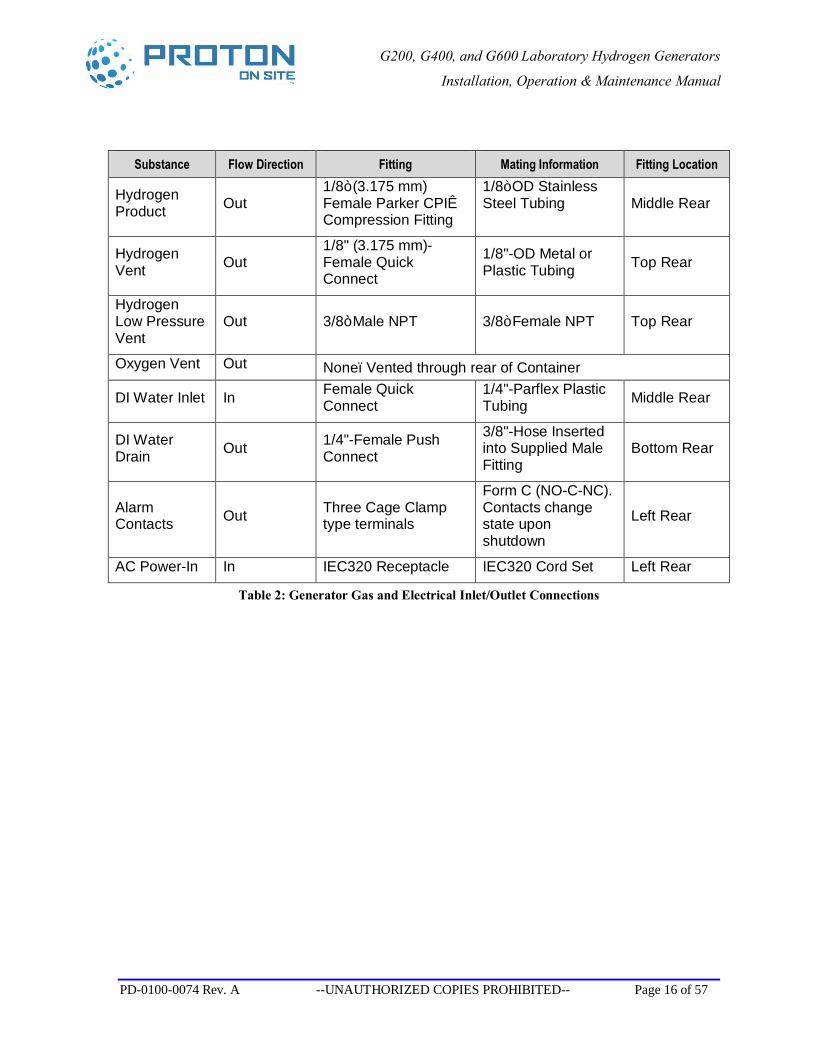
Substance Flow Direction Fitting Mating Information Fitting Location
Hydrogen Product Out
1/8” (3.175 mm) Female Parker CPI™ Compression Fitting
1/8” OD Stainless Steel Tubing Middle Rear
Hydrogen Vent Out
1/8" (3.175 mm)- Female Quick Connect
1/8"-OD Metal or Plastic Tubing Top Rear
Hydrogen Low Pressure Vent
Out 3/8” Male NPT 3/8” Female NPT Top Rear
Oxygen Vent Out None–Vented through rear of Container
DI Water Inlet In Female Quick Connect
1/4"-Parflex Plastic Tubing Middle Rear
DI Water Drain Out 1/4"-Female Push
Connect
3/8"-Hose Inserted into Supplied Male Fitting
Bottom Rear
Alarm Contacts Out Three Cage Clamp
type terminals
Form C (NO-C-NC). Contacts change state upon shutdown
Left Rear
AC Power-In In IEC320 Receptacle IEC320 Cord Set Left Rear
Table 2: Generator Gas and Electrical Inlet/Outlet Connections
G200, G400, and G600 Laboratory Hydrogen Generators
Installation, Operation & Maintenance Manual
PD-0100-0074 Rev. A --UNAUTHORIZED COPIES PROHIBITED-- Page 17 of 57
2 Safety
The safety guidelines below may not cover all situations. If there are concerns or questions, please contact Proton OnSite Technical Service or check with local authorities.
THE G200, G400, OR G600 HYDROGEN GENERATOR IS A LABORATORY INSTRUMENT DESIGNED FOR OPERATION BY TRAINED PERSONNEL. UNSAFE CONDITIONS MAY RESULT IF THE GENERATOR IS OPERATED BY UNTRAINED PERSONNEL OR PERSONNEL UNFAMILIAR WITH HYDROGEN SAFETY.
ALL PERSONNEL HANDLING, USING OR MAINTAINING THIS GENERATOR MUST EMPLOY SAFE WORKING PRACTICES AND OBSERVE ALL RELEVANT LOCAL HEALTH AND SAFETY REGULATIONS.
2.1 Using Hydrogen Gas
Hydrogen is odorless, tasteless, colorless, and highly flammable. It is highly combustible in the presence of oxygen and burns with a colorless flame.
Never directly inhale the gas produced. Check gas connections with a liquid leak detector when you initially install, or after a service event when gas plumbing was disconnected.
Leaking gas may be hot and pose a burn danger. If you are not in danger, stop the flow of gas and use water to cool the area. The lower flammability limit of hydrogen is 4 percent hydrogen in air by volume. If fire occurs, do not attempt to extinguish flames; allow the fire to burn out.
Avoid overexposure to hydrogen. Hydrogen is non-toxic, but it can act as a simple asphyxiant by displacing the oxygen in the air. Effects of oxygen deficiency, resulting from simple asphyxiants, include rapid breathing, diminished mental alertness, impaired muscular coordination, faulty judgment, depression of all sensations, emotional instability, and fatigue. As asphyxiation progresses, nausea, vomiting, prostration, and loss of consciousness may result.
The G200, G400, or G600 hydrogen generator, in addition to generating pressurized hydrogen product, also produces a small flow of byproduct oxygen at just over atmospheric pressure. This oxygen is vented from an outlet in the top of the internal water tank and swept from the cabinet with the cooling air. The generator must be operated in an area with sufficient air circulation to allow this oxygen to disperse. The power switch and electrical disconnect (removable cord set) are located at the back of the unit and must be accessible at all times during operation of the generator. Refer to Product Specifications, (Table 1, Page 14) for recommended ventilation.
G200, G400, and G600 Laboratory Hydrogen Generators
Installation, Operation & Maintenance Manual
PD-0100-0074 Rev. A --UNAUTHORIZED COPIES PROHIBITED-- Page 18 of 57
FIRE OR EXPLOSION—KEEP ALL SOURCES OF IGNITION AWAY FROM HYDROGEN.
2.2 Safety Devices
MAXIMUM PRESSURE: An internal safety valve prevents the generator pressure from exceeding 9 barg (130 psi). The hydrogen is vented out the hydrogen vent connection.
2.3 Technical Service Contact Information
Proton OnSite Technical Service can be contacted as follows:
Proton OnSite 10 Technology Drive Wallingford, CT 06492 203-949-8697 203-678-2000 [email protected] www.protononsite.com
G200, G400, and G600 Laboratory Hydrogen Generators
Installation, Operation & Maintenance Manual
PD-0100-0074 Rev. A --UNAUTHORIZED COPIES PROHIBITED-- Page 19 of 57
3 Placement
3.1 Unpacking the Generator
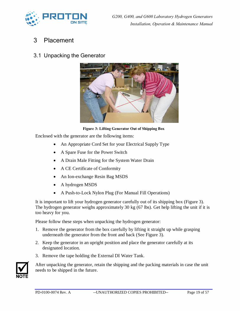
Figure 3: Lifting Generator Out of Shipping Box
Enclosed with the generator are the following items:
• An Appropriate Cord Set for your Electrical Supply Type
• A Spare Fuse for the Power Switch
• A Drain Male Fitting for the System Water Drain
• A CE Certificate of Conformity
• An Ion-exchange Resin Bag MSDS
• A hydrogen MSDS
• A Push-to-Lock Nylon Plug (For Manual Fill Operations)
It is important to lift your hydrogen generator carefully out of its shipping box (Figure 3). The hydrogen generator weighs approximately 30 kg (67 lbs). Get help lifting the unit if it is too heavy for you.
Please follow these steps when unpacking the hydrogen generator:
1. Remove the generator from the box carefully by lifting it straight up while grasping underneath the generator from the front and back (See Figure 3).
2. Keep the generator in an upright position and place the generator carefully at its designated location.
3. Remove the tape holding the External DI Water Tank.
After unpacking the generator, retain the shipping and the packing materials in case the unit needs to be shipped in the future.
G200, G400, and G600 Laboratory Hydrogen Generators
Installation, Operation & Maintenance Manual
PD-0100-0074 Rev. A --UNAUTHORIZED COPIES PROHIBITED-- Page 20 of 57
If you must ship the G200, G400, or G600 hydrogen generator for any reason, please follow these steps:
Drain all the water from the DI water tank, remove the ion-exchange resin bag, and reinstall the water tank cap.
Properly package the unit and ship it in an upright position. Ship the unit in a manner to prevent freezing. Freezing can cause irreversible damage to the system. If you have discarded the original packaging, please contact Proton onsite or your supplier to replace the container or box.
3.2 Positioning the Generator
The G200, G400, or G600 hydrogen generator is designed for indoor, laboratory installation. AC power and de-ionized water that meets the specifications outlined in Product Specifications (Section 1.2 on Page 13) are the only utilities required. Verify where the generator is located so that placing it complies with local safety regulations.
Use the following instructions for placing your hydrogen generator:
1. Place the generator in a location that meets the technical specifications from Product Specifications (Section 1.2 on Page 13). Some specifications are highlighted below. We recommend that the generator be situated as close to the gas application as possible.
2. When placing the unit, keep in mind that you must always have access to controls, water fill inlets, gas outlets, and power and control wiring.
3. Make sure that the unit is placed in a clean and well-ventilated indoor environment, where ventilation should exceed >4 Nm³/Hr (>150SCFH)
4. Protect the generator from water splashes.
5. Keep the unit well away from sources of high heat, static electricity, and open flames. 6. Install unit on a level site (+/- 3° required).
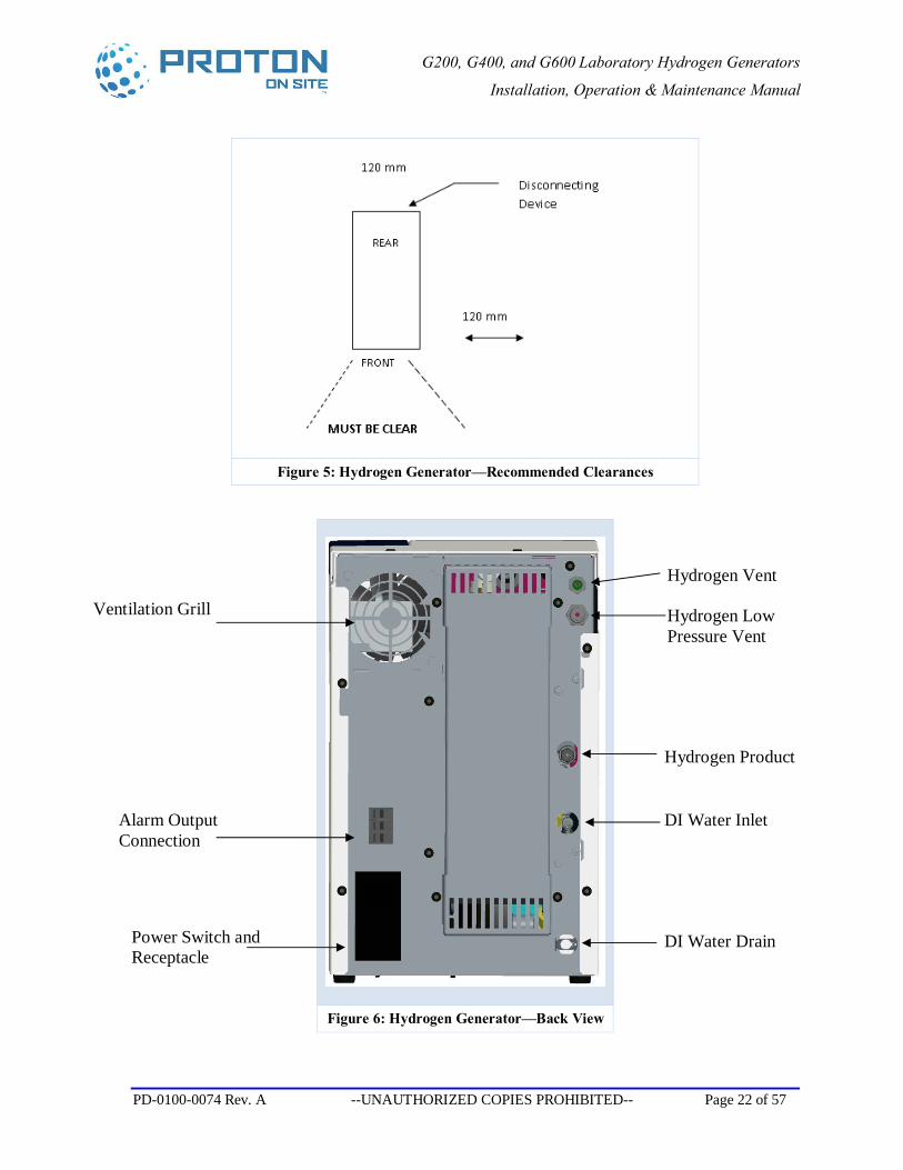
7. Check that the front of the unit is kept unobstructed and clear of other objects (Figure 4 shows the front of the generator). Figure 5 illustrates minimum clearances.
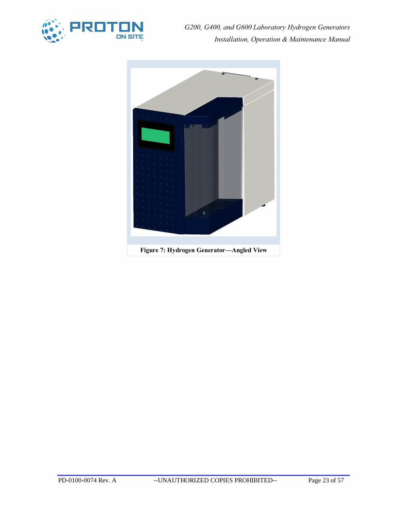
8. Allow minimum clearance of 120 mm (4.75 inches) at the rear (Figure 6) and on the right-hand side (Figure 7) of the generator so that the cabinet is always well-ventilated.
9. The power switch and electrical disconnect (removable cord set) are located at the back of the unit (Figure 6) and must be accessible at all times when the generator is running. Position the unit so that it is possible to operate the power switch
10. Comply with necessary ambient ventilation, temperature, and humidity conditions.
G200, G400, and G600 Laboratory Hydrogen Generators
Installation, Operation & Maintenance Manual
PD-0100-0074 Rev. A --UNAUTHORIZED COPIES PROHIBITED-- Page 21 of 57
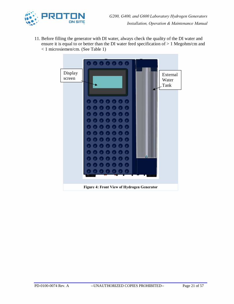
11. Before filling the generator with DI water, always check the quality of the DI water and ensure it is equal to or better than the DI water feed specification of > 1 Megohm/cm and < 1 microsiemen/cm. (See Table 1)
Figure 4: Front View of Hydrogen Generator
Display screen
External Water Tank
G200, G400, and G600 Laboratory Hydrogen Generators
Installation, Operation & Maintenance Manual
PD-0100-0074 Rev. A --UNAUTHORIZED COPIES PROHIBITED-- Page 22 of 57
Figure 5: Hydrogen Generator—Recommended Clearances
Figure 6: Hydrogen Generator—Back View
Hydrogen Vent
Hydrogen Low Pressure Vent
Hydrogen Product
DI Water Inlet
DI Water Drain Power Switch and Receptacle
Alarm Output Connection
Ventilation Grill
G200, G400, and G600 Laboratory Hydrogen Generators
Installation, Operation & Maintenance Manual
PD-0100-0074 Rev. A --UNAUTHORIZED COPIES PROHIBITED-- Page 23 of 57
Figure 7: Hydrogen Generator—Angled View
G200, G400, and G600 Laboratory Hydrogen Generators
Installation, Operation & Maintenance Manual
PD-0100-0074 Rev. A --UNAUTHORIZED COPIES PROHIBITED-- Page 24 of 57
4 Installation Procedure
4.1 Mechanical Setup
This section provides a detailed description of the mechanical setup requirements.
1. Do not connect the hydrogen supply system tubing to the generator until the hydrogen supply system layout and fittings are finalized, purged with inert gas to remove oxygen, and leak checked. After leak checking, purge the hydrogen supply tubing with nitrogen or helium for at least 15 minutes to remove oxygen and any water vapor that may be in the tubing.
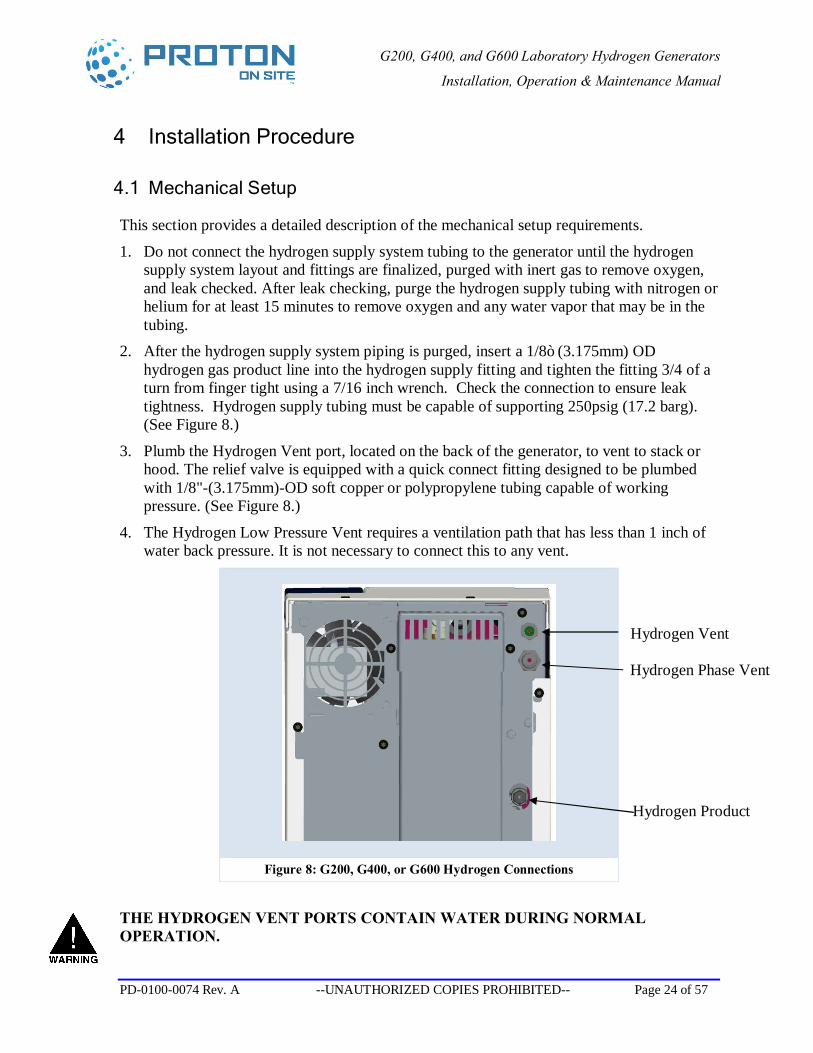
2. After the hydrogen supply system piping is purged, insert a 1/8” (3.175mm) OD hydrogen gas product line into the hydrogen supply fitting and tighten the fitting 3/4 of a turn from finger tight using a 7/16 inch wrench. Check the connection to ensure leak tightness. Hydrogen supply tubing must be capable of supporting 250psig (17.2 barg). (See Figure 8.)
3. Plumb the Hydrogen Vent port, located on the back of the generator, to vent to stack or hood. The relief valve is equipped with a quick connect fitting designed to be plumbed with 1/8"-(3.175mm)-OD soft copper or polypropylene tubing capable of working pressure. (See Figure 8.)
4. The Hydrogen Low Pressure Vent requires a ventilation path that has less than 1 inch of water back pressure. It is not necessary to connect this to any vent.
Figure 8: G200, G400, or G600 Hydrogen Connections
THE HYDROGEN VENT PORTS CONTAIN WATER DURING NORMAL OPERATION.
Hydrogen Vent
Hydrogen Phase Vent
Hydrogen Product
G200, G400, and G600 Laboratory Hydrogen Generators
Installation, Operation & Maintenance Manual
PD-0100-0074 Rev. A --UNAUTHORIZED COPIES PROHIBITED-- Page 25 of 57
4.2 Electrical Setup
This section provides a detailed description of the electrical setup requirements.
1. Determine the electrical supply outlet that would provide power to the generator. 2. Check that the electrical supply is properly grounded and the voltage corresponds with
the generator rating plate.
DO NOT BYPASS GROUND PIN. 3. Proton OnSite recommends using an uninterruptible power supply in locations where
power failures are common to assure reliable hydrogen generation.
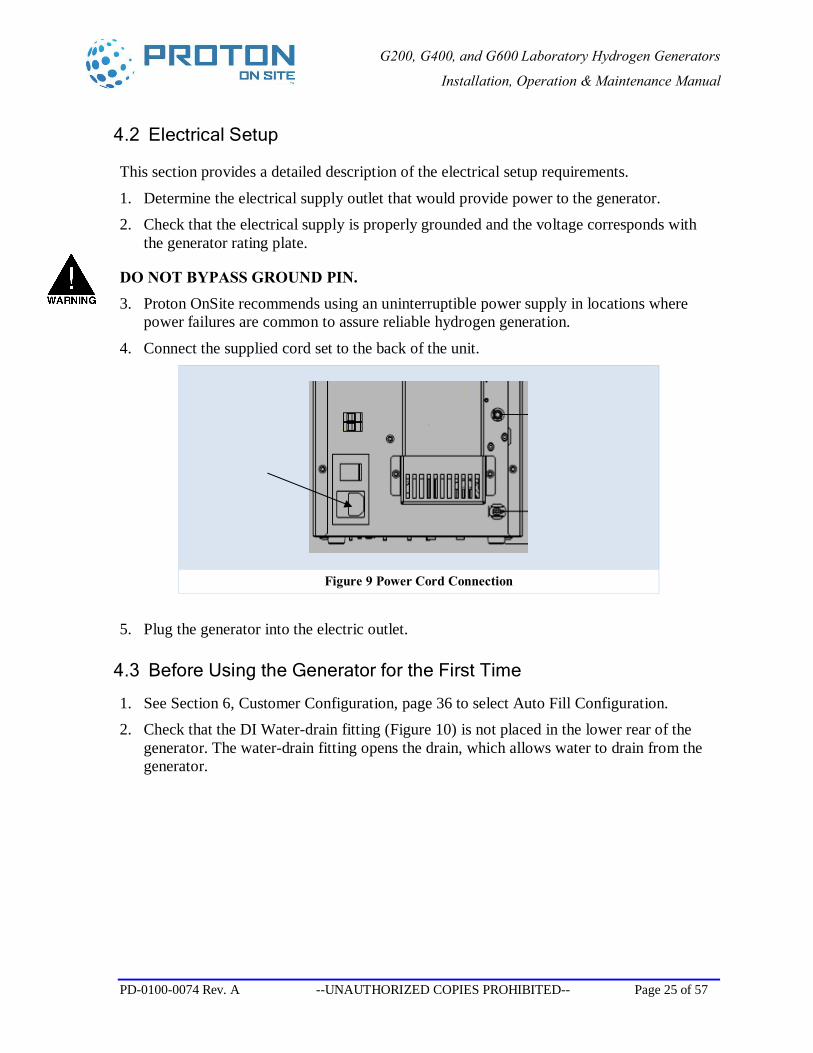
4. Connect the supplied cord set to the back of the unit.
Figure 9 Power Cord Connection
5. Plug the generator into the electric outlet.
4.3 Before Using the Generator for the First Time
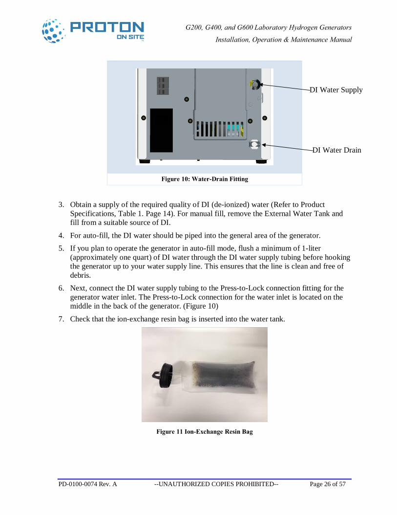
1. See Section 6, Customer Configuration, page 36 to select Auto Fill Configuration. 2. Check that the DI Water-drain fitting (Figure 10) is not placed in the lower rear of the
generator. The water-drain fitting opens the drain, which allows water to drain from the generator.
G200, G400, and G600 Laboratory Hydrogen Generators
Installation, Operation & Maintenance Manual
PD-0100-0074 Rev. A --UNAUTHORIZED COPIES PROHIBITED-- Page 26 of 57
Figure 10: Water-Drain Fitting
3. Obtain a supply of the required quality of DI (de-ionized) water (Refer to Product Specifications, Table 1. Page 14). For manual fill, remove the External Water Tank and fill from a suitable source of DI.
4. For auto-fill, the DI water should be piped into the general area of the generator. 5. If you plan to operate the generator in auto-fill mode, flush a minimum of 1-liter
(approximately one quart) of DI water through the DI water supply tubing before hooking the generator up to your water supply line. This ensures that the line is clean and free of debris.
6. Next, connect the DI water supply tubing to the Press-to-Lock connection fitting for the generator water inlet. The Press-to-Lock connection for the water inlet is located on the middle in the back of the generator. (Figure 10)
7. Check that the ion-exchange resin bag is inserted into the water tank.
Figure 11 Ion-Exchange Resin Bag
DI Water Drain
DI Water Supply
G200, G400, and G600 Laboratory Hydrogen Generators
Installation, Operation & Maintenance Manual
PD-0100-0074 Rev. A --UNAUTHORIZED COPIES PROHIBITED-- Page 27 of 57
5 Operation
5.1 Startup—System Operation or Interface
The Factory Default for automatic refill is from the installed EXTERNAL WATER tank. If auto-refill is desired from a site DI water supply see section 6.1 for customer configuration steps.
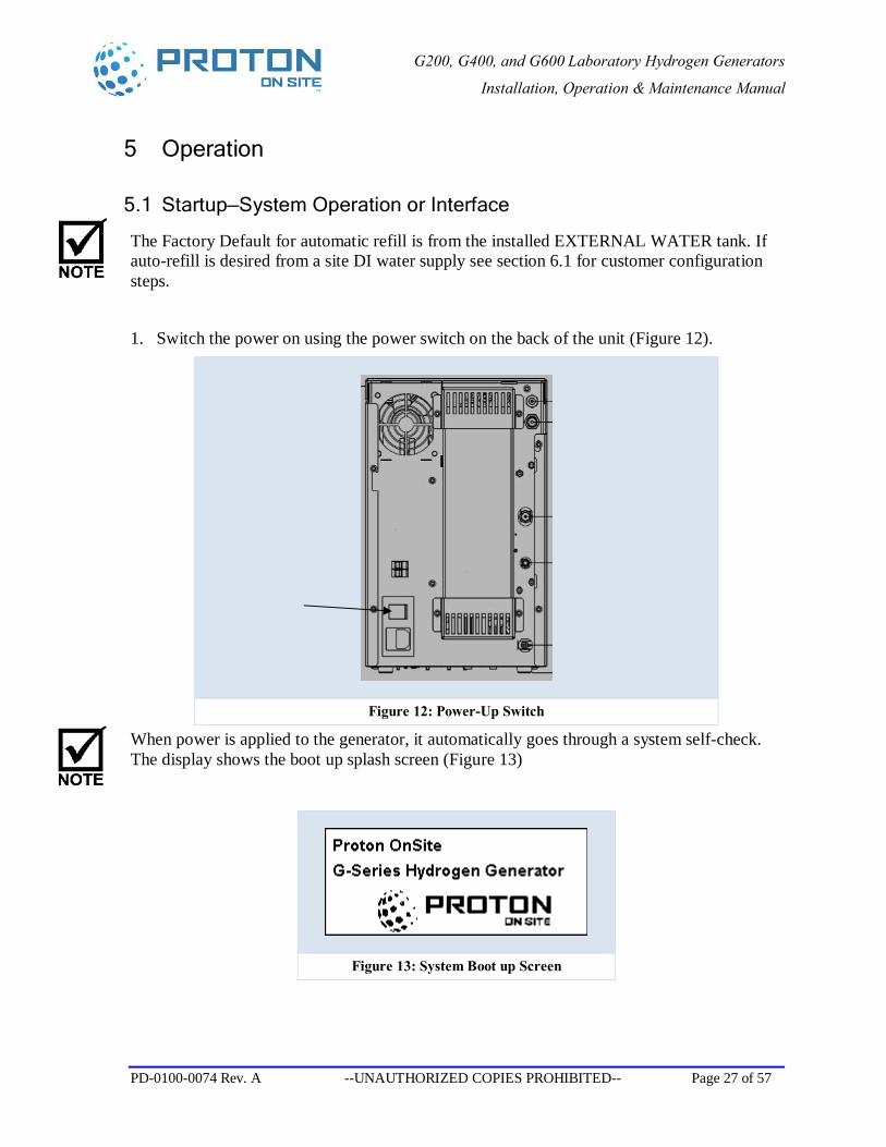
1. Switch the power on using the power switch on the back of the unit (Figure 12).
Figure 12: Power-Up Switch
When power is applied to the generator, it automatically goes through a system self-check. The display shows the boot up splash screen (Figure 13)
Figure 13: System Boot up Screen
G200, G400, and G600 Laboratory Hydrogen Generators
Installation, Operation & Maintenance Manual
PD-0100-0074 Rev. A --UNAUTHORIZED COPIES PROHIBITED-- Page 28 of 57
2. Notice that the Startup Splash Screen is shown in the display (Figure 13) for 3 seconds and then the display shifts to the main operating screen (Figure 14).
Figure 14: Main Operating Screen
3. To read and/or set the pressure set-point, press the pressure set point button. Press the pressure set point number on the display and enter the desired pressure using the displayed keypad. Press the Main button to return to the Main Operating Screen
Figure 15: Pressure Set-Point Figure 16: Keypad
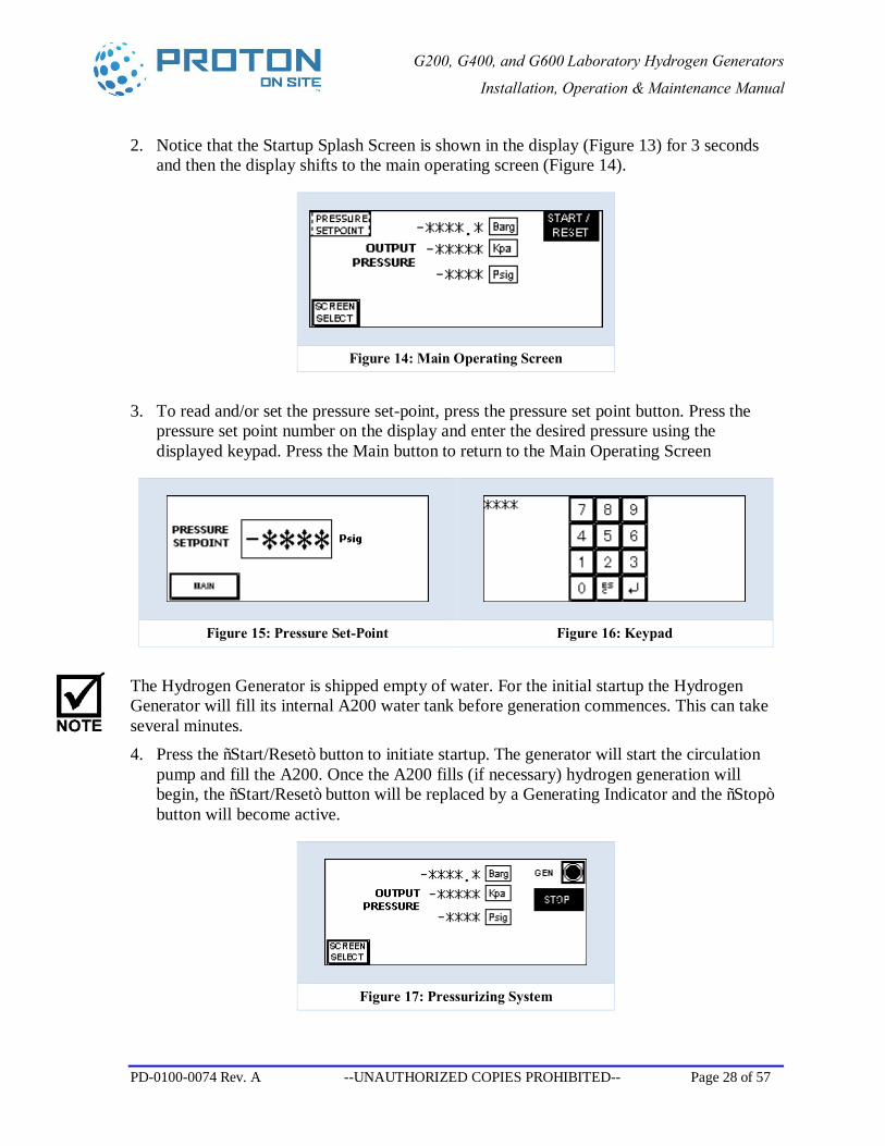
The Hydrogen Generator is shipped empty of water. For the initial startup the Hydrogen Generator will fill its internal A200 water tank before generation commences. This can take several minutes. 4. Press the “Start/Reset” button to initiate startup. The generator will start the circulation
pump and fill the A200. Once the A200 fills (if necessary) hydrogen generation will begin, the “Start/Reset” button will be replaced by a Generating Indicator and the “Stop” button will become active.
Figure 17: Pressurizing System
G200, G400, and G600 Laboratory Hydrogen Generators
Installation, Operation & Maintenance Manual
PD-0100-0074 Rev. A --UNAUTHORIZED COPIES PROHIBITED-- Page 29 of 57
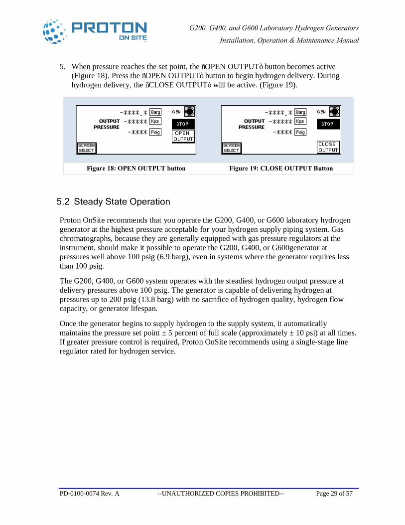
5. When pressure reaches the set point, the “OPEN OUTPUT” button becomes active (Figure 18). Press the “OPEN OUTPUT” button to begin hydrogen delivery. During hydrogen delivery, the “CLOSE OUTPUT” will be active. (Figure 19).
Figure 18: OPEN OUTPUT button Figure 19: CLOSE OUTPUT Button
5.2 Steady State Operation
Proton OnSite recommends that you operate the G200, G400, or G600 laboratory hydrogen generator at the highest pressure acceptable for your hydrogen supply piping system. Gas chromatographs, because they are generally equipped with gas pressure regulators at the instrument, should make it possible to operate the G200, G400, or G600generator at pressures well above 100 psig (6.9 barg), even in systems where the generator requires less than 100 psig.
The G200, G400, or G600 system operates with the steadiest hydrogen output pressure at delivery pressures above 100 psig. The generator is capable of delivering hydrogen at pressures up to 200 psig (13.8 barg) with no sacrifice of hydrogen quality, hydrogen flow capacity, or generator lifespan.
Once the generator begins to supply hydrogen to the supply system, it automatically maintains the pressure set point ± 5 percent of full scale (approximately ± 10 psi) at all times. If greater pressure control is required, Proton OnSite recommends using a single-stage line regulator rated for hydrogen service.
G200, G400, and G600 Laboratory Hydrogen Generators
Installation, Operation & Maintenance Manual
PD-0100-0074 Rev. A --UNAUTHORIZED COPIES PROHIBITED-- Page 30 of 57
5.3 Standby Mode
Standby Mode allows the G200, G400, or G600 hydrogen generator to idle at the pressure set point without delivering the hydrogen product to your process. Standby Mode is ideal for short durations when hydrogen is not needed, such as overnight.
If hydrogen is not needed for a longer period of time, such as a weekend, Proton OnSite recommends, but does not require, completely shutting down the unit.
Use the following instructions for placing the unit in Standby Mode:
1. Press the “CLOSE OUTPUT” button to cease hydrogen delivery (Figure 19). 2. The “OPEN OUTPUT” button becomes active while in Standby Mode and system
pressure remains at set point. (Figure 18)
This procedure cycles generation to maintain internal hydrogen pressure within the generator and to maintain all internal systems in a “hot” condition, which is when the generator is ready to deliver hydrogen instantly.
To restart hydrogen delivery, simply depress the “OPEN OUTPUT” button to open the hydrogen delivery valve.
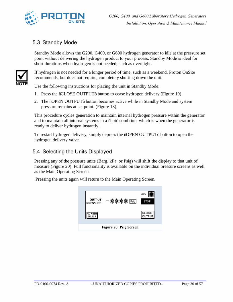
5.4 Selecting the Units Displayed
Pressing any of the pressure units (Barg, kPa, or Psig) will shift the display to that unit of measure (Figure 20). Full functionality is available on the individual pressure screens as well as the Main Operating Screen.
Pressing the units again will return to the Main Operating Screen.
Figure 20: Psig Screen
G200, G400, and G600 Laboratory Hydrogen Generators
Installation, Operation & Maintenance Manual
PD-0100-0074 Rev. A --UNAUTHORIZED COPIES PROHIBITED-- Page 31 of 57
5.5 Shutdown
Under normal circumstances, no special procedures are required for shutdown of the G200, G400, or G600 hydrogen generator. Simply use the electronic controls as follows:
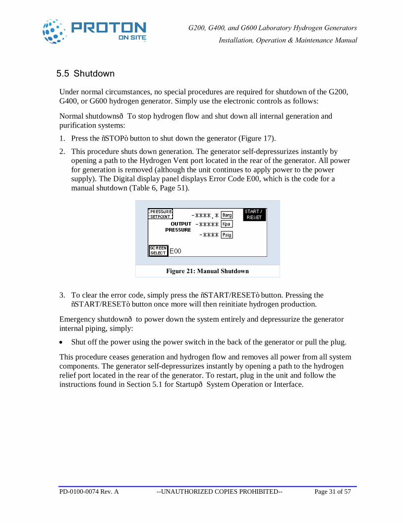
Normal shutdowns—To stop hydrogen flow and shut down all internal generation and purification systems: 1. Press the “STOP” button to shut down the generator (Figure 17).
2. This procedure shuts down generation. The generator self-depressurizes instantly by opening a path to the Hydrogen Vent port located in the rear of the generator. All power for generation is removed (although the unit continues to apply power to the power supply). The Digital display panel displays Error Code E00, which is the code for a manual shutdown (Table 6, Page 51).
Figure 21: Manual Shutdown
3. To clear the error code, simply press the “START/RESET” button. Pressing the “START/RESET” button once more will then reinitiate hydrogen production.
Emergency shutdown—to power down the system entirely and depressurize the generator internal piping, simply:
• Shut off the power using the power switch in the back of the generator or pull the plug.
This procedure ceases generation and hydrogen flow and removes all power from all system components. The generator self-depressurizes instantly by opening a path to the hydrogen relief port located in the rear of the generator. To restart, plug in the unit and follow the instructions found in Section 5.1 for Startup—System Operation or Interface.
G200, G400, and G600 Laboratory Hydrogen Generators
Installation, Operation & Maintenance Manual
PD-0100-0074 Rev. A --UNAUTHORIZED COPIES PROHIBITED-- Page 32 of 57
5.6 Alarm Contact Output
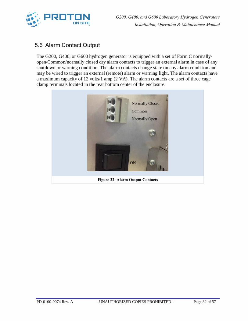
The G200, G400, or G600 hydrogen generator is equipped with a set of Form C normally-open/Common/normally closed dry alarm contacts to trigger an external alarm in case of any shutdown or warning condition. The alarm contacts change state on any alarm condition and may be wired to trigger an external (remote) alarm or warning light. The alarm contacts have a maximum capacity of 12 volts/1 amp (2 VA). The alarm contacts are a set of three cage clamp terminals located in the rear bottom center of the enclosure.
Figure 22: Alarm Output Contacts
Normally Open
Common
Normally Closed
ON
G200, G400, and G600 Laboratory Hydrogen Generators
Installation, Operation & Maintenance Manual
PD-0100-0074 Rev. A --UNAUTHORIZED COPIES PROHIBITED-- Page 33 of 57
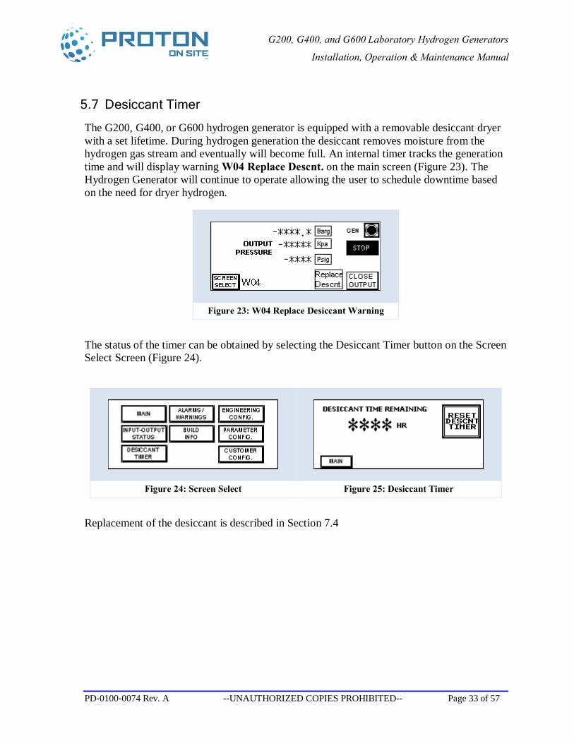
5.7 Desiccant Timer
The G200, G400, or G600 hydrogen generator is equipped with a removable desiccant dryer with a set lifetime. During hydrogen generation the desiccant removes moisture from the hydrogen gas stream and eventually will become full. An internal timer tracks the generation time and will display warning W04 Replace Descnt. on the main screen (Figure 23). The Hydrogen Generator will continue to operate allowing the user to schedule downtime based on the need for dryer hydrogen.
Figure 23: W04 Replace Desiccant Warning
The status of the timer can be obtained by selecting the Desiccant Timer button on the Screen Select Screen (Figure 24).
Figure 24: Screen Select Figure 25: Desiccant Timer
Replacement of the desiccant is described in Section 7.4
G200, G400, and G600 Laboratory Hydrogen Generators
Installation, Operation & Maintenance Manual
PD-0100-0074 Rev. A --UNAUTHORIZED COPIES PROHIBITED-- Page 34 of 57
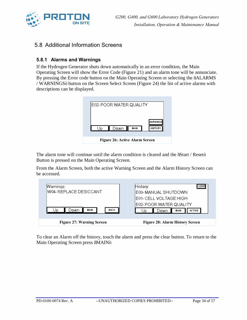
5.8 Additional Information Screens
5.8.1 Alarms and Warnings If the Hydrogen Generator shuts down automatically in an error condition, the Main Operating Screen will show the Error Code (Figure 21) and an alarm tone will be annunciate. By pressing the Error code button on the Main Operating Screen or selecting the “ALARMS / WARNINGS” button on the Screen Select Screen (Figure 24) the list of active alarms with descriptions can be displayed.
Figure 26: Active Alarm Screen
The alarm tone will continue until the alarm condition is cleared and the “Start / Reset” Button is pressed on the Main Operating Screen. From the Alarm Screen, both the active Warning Screen and the Alarm History Screen can be accessed.
Figure 27: Warning Screen Figure 28: Alarm History Screen
To clear an Alarm off the history, touch the alarm and press the clear button. To return to the Main Operating Screen press “MAIN”
G200, G400, and G600 Laboratory Hydrogen Generators
Installation, Operation & Maintenance Manual
PD-0100-0074 Rev. A --UNAUTHORIZED COPIES PROHIBITED-- Page 35 of 57
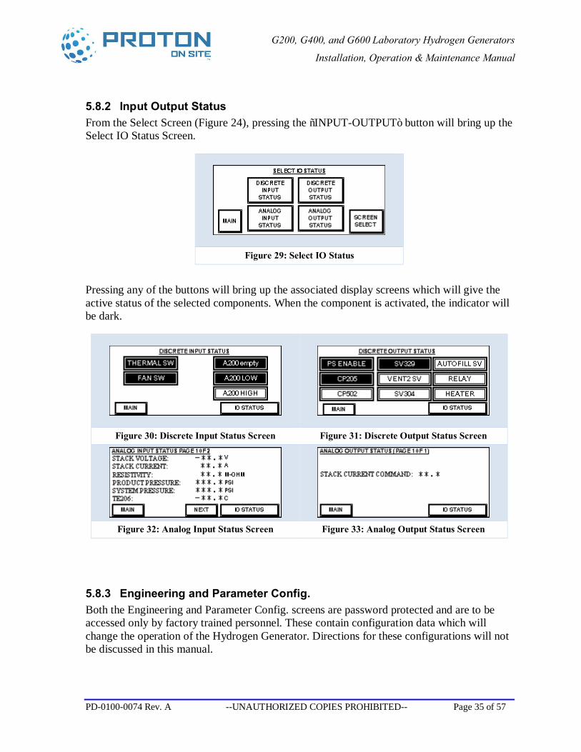
5.8.2 Input Output Status From the Select Screen (Figure 24), pressing the “INPUT-OUTPUT” button will bring up the Select IO Status Screen.
Figure 29: Select IO Status
Pressing any of the buttons will bring up the associated display screens which will give the active status of the selected components. When the component is activated, the indicator will be dark.
Figure 30: Discrete Input Status Screen Figure 31: Discrete Output Status Screen
Figure 32: Analog Input Status Screen Figure 33: Analog Output Status Screen
5.8.3 Engineering and Parameter Config. Both the Engineering and Parameter Config. screens are password protected and are to be accessed only by factory trained personnel. These contain configuration data which will change the operation of the Hydrogen Generator. Directions for these configurations will not be discussed in this manual.
G200, G400, and G600 Laboratory Hydrogen Generators
Installation, Operation & Maintenance Manual
PD-0100-0074 Rev. A --UNAUTHORIZED COPIES PROHIBITED-- Page 36 of 57
6 Customer Configuration
6.1 Auto-Fill
The Factory Default for automatic refill is from the installed External Water Tank
The G200, G400, or G600 laboratory hydrogen generator is equipped with auto-fill as a standard feature. The generator water supply may be provided by either method:
• Manually filling with DI Water using the External Water Tank (Figure 4)
• Automatic Filling using a DI water supply connected to the auto-fill water inlet Press-to-Lock Fitting at the back of the generator (Figure 10)
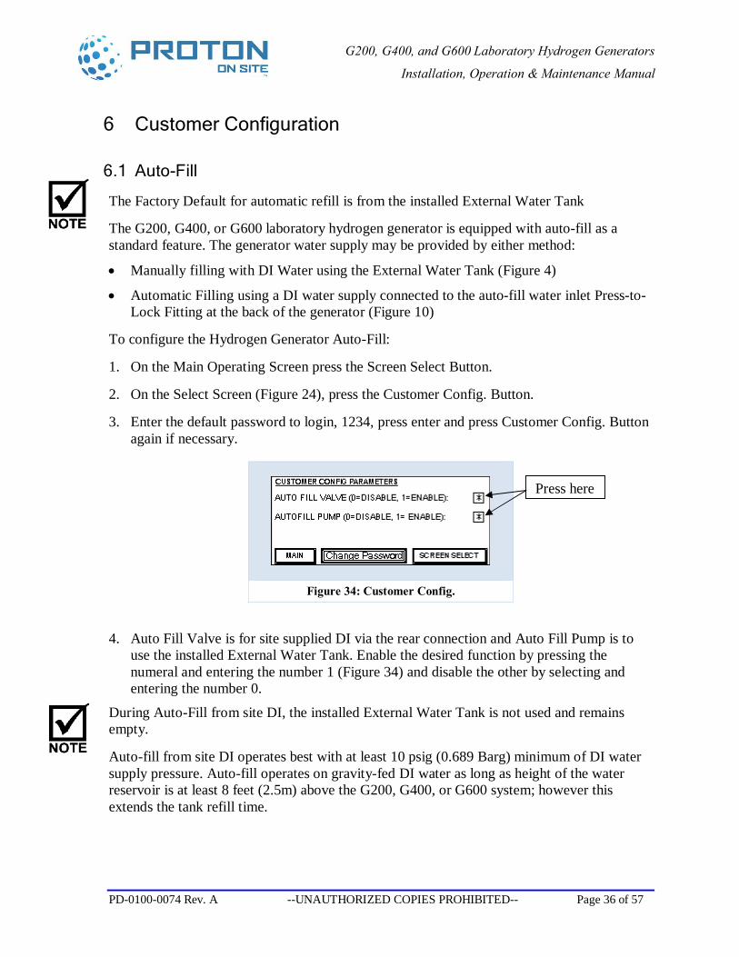
To configure the Hydrogen Generator Auto-Fill:
1. On the Main Operating Screen press the Screen Select Button.
2. On the Select Screen (Figure 24), press the Customer Config. Button.
3. Enter the default password to login, 1234, press enter and press Customer Config. Button again if necessary.
4. Auto Fill Valve is for site supplied DI via the rear connection and Auto Fill Pump is to use the installed External Water Tank. Enable the desired function by pressing the numeral and entering the number 1 (Figure 34) and disable the other by selecting and entering the number 0.
During Auto-Fill from site DI, the installed External Water Tank is not used and remains empty.
Auto-fill from site DI operates best with at least 10 psig (0.689 Barg) minimum of DI water supply pressure. Auto-fill operates on gravity-fed DI water as long as height of the water reservoir is at least 8 feet (2.5m) above the G200, G400, or G600 system; however this extends the tank refill time.
Figure 34: Customer Config.
Press here
G200, G400, and G600 Laboratory Hydrogen Generators
Installation, Operation & Maintenance Manual
PD-0100-0074 Rev. A --UNAUTHORIZED COPIES PROHIBITED-- Page 37 of 57
During auto-fill from the installed External Water Tank, the water level in the tank will go down during generation. When level reaches empty as indicated by no water within the tank, remove the tank, refill from an approved DI water source and replace. The Hydrogen Generator will continue to operate during this refill action.
To ensure continuous operation with manual fill systems, regularly check the water level and refill as necessary to maintain the water level. If the water is not refilled, the Hydrogen Generator will continue to operate until the internal volume of water is depleted and then shutdown displaying an E03, A200 Empty Alarm.
Before filling the generator with DI water, always check the quality of the DI water and ensure it is equal to or better than the DI water feed specification. (Refer to Product Specifications, 1.2. Page 13)
G200, G400, and G600 Laboratory Hydrogen Generators
Installation, Operation & Maintenance Manual
PD-0100-0074 Rev. A --UNAUTHORIZED COPIES PROHIBITED-- Page 38 of 57
7 Maintenance
7.1 Maintenance Schedule
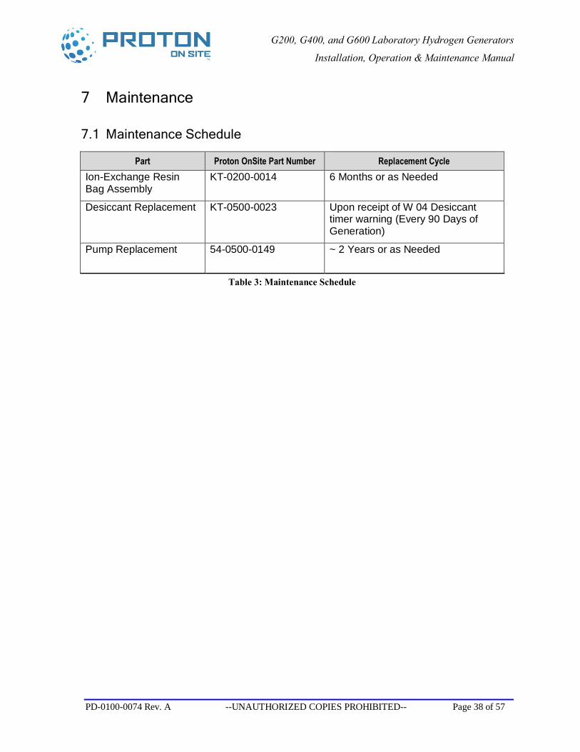
Part Proton OnSite Part Number Replacement Cycle Ion-Exchange Resin Bag Assembly
KT-0200-0014 6 Months or as Needed
Desiccant Replacement KT-0500-0023
Upon receipt of W 04 Desiccant timer warning (Every 90 Days of Generation)
Pump Replacement 54-0500-0149
~ 2 Years or as Needed
Table 3: Maintenance Schedule
G200, G400, and G600 Laboratory Hydrogen Generators
Installation, Operation & Maintenance Manual
PD-0100-0074 Rev. A --UNAUTHORIZED COPIES PROHIBITED-- Page 39 of 57
7.2 Ion-Exchange Resin Bag
The G200, G400, or G600 hydrogen generator is equipped with an ion-exchange resin bag, which is similar in appearance to a teabag, and is used to ensure that the re-circulated water within the generator is maintained as pure (i.e. ion-free) as possible. The ion-exchange resin bag is attached to the black-resin, bag-cap and hangs in the internal water container A200.] The ion-exchange resin scavenges any remaining ions from the circulating water and helps to stop the water conductivity from rising during operation.
It is important to replace this ion-exchange resin bag at the recommended intervals to ensure that it continues to provide its designed protection.
The ion-exchange resin bag cannot be used to clean impure water added to the generator - its ion capacity and ion-exchange efficiency are designed only to maintain the quality of the Type II DI water re-circulated within the system.
The bag should be replaced:
• If the conductivity is rising to alarming levels during operation when the same quality water is being used consistently, or at least every six months.
Replacement bags are available from Proton OnSite or from your generator supplier. Follow these following instructions to install a new ion-exchange resin bag: 1. Cover your hands using powder-free latex or similar impermeable gloves when handling
the ion-exchange resin bag to protect the DI water system from contamination. 2. Remove the top cover of the Hydrogen Generator.
G200, G400, and G600 Laboratory Hydrogen Generators
Installation, Operation & Maintenance Manual
PD-0100-0074 Rev. A --UNAUTHORIZED COPIES PROHIBITED-- Page 40 of 57
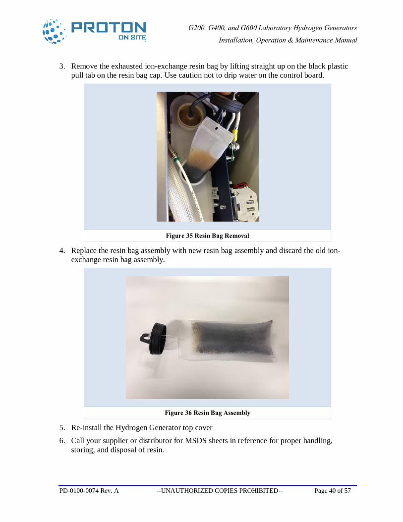
3. Remove the exhausted ion-exchange resin bag by lifting straight up on the black plastic pull tab on the resin bag cap. Use caution not to drip water on the control board.
Figure 35 Resin Bag Removal
4. Replace the resin bag assembly with new resin bag assembly and discard the old ion-exchange resin bag assembly.
Figure 36 Resin Bag Assembly
5. Re-install the Hydrogen Generator top cover 6. Call your supplier or distributor for MSDS sheets in reference for proper handling,
storing, and disposal of resin.
G200, G400, and G600 Laboratory Hydrogen Generators
Installation, Operation & Maintenance Manual
PD-0100-0074 Rev. A --UNAUTHORIZED COPIES PROHIBITED-- Page 41 of 57
7.3 Water Quality
The G200, G400, or G600 hydrogen generator has a built in conductivity meter that helps to protect the electrochemical cell from damage due to substandard DI water. If the conductivity meter detects a water problem, the generator shuts down to minimize damage to the cell stack and the digital pressure display presents the error code E-02—Poor Water Quality.
It is important to understand that many factors can affect the quality of DI water. Once it is dispensed from your laboratory DI water system, the DI water conductivity increases rapidly. ASTM Type II DI water dispensed and left sitting in an open container absorbs atmospheric carbon dioxide and may trigger the water conductivity sensor in the G200, G400, or G600, indicating poor water quality.
Please use fresh ASTM Type II DI water. Start the G200, G400, or G600 unit up as soon as possible after filling it with Type II DI water that meets the requirements shown in Table 1 (Refer to Product Specifications, 1.2., Page 13). Once the water is circulating within the G200, G400, or G600 system, the ion-exchange resin bag helps to keep it clean.
The G200, G400, or G600 hydrogen generator requires astm type ii reagent grade water or better ( > 1 MΩ/cm (< 1 mS/cm) <0.5ppm total dissolved solids per Table 1). Do not substitute distilled water or other. Using lower quality DI water or distilled water in your hydrogen generator irreversibly damages the hydrogen generating cell stack and voids the warranty.
G200, G400, and G600 Laboratory Hydrogen Generators
Installation, Operation & Maintenance Manual
PD-0100-0074 Rev. A --UNAUTHORIZED COPIES PROHIBITED-- Page 42 of 57
7.4 Desiccant Replacement
1. On the Main Operating Screen press the “Stop” button to stop Generation.
2. Turn off Hydrogen Generator with main power switch and remove power cord.
3. Remove the top and left side of the Hydrogen Generator.
The desiccant cartridge employs o-ring seal fittings. Caution must be taken to ensure the o-rings are not damaged or lost. Open the manual valve to release stored hydrogen in desiccant canister.
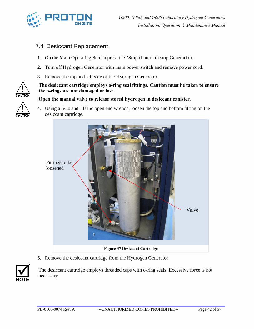
4. Using a 5/8” and 11/16” open end wrench, loosen the top and bottom fitting on the desiccant cartridge.
Figure 37 Desiccant Cartridge
5. Remove the desiccant cartridge from the Hydrogen Generator
The desiccant cartridge employs threaded caps with o-ring seals. Excessive force is not necessary
Fittings to be loosened
Valve
G200, G400, and G600 Laboratory Hydrogen Generators
Installation, Operation & Maintenance Manual
PD-0100-0074 Rev. A --UNAUTHORIZED COPIES PROHIBITED-- Page 43 of 57
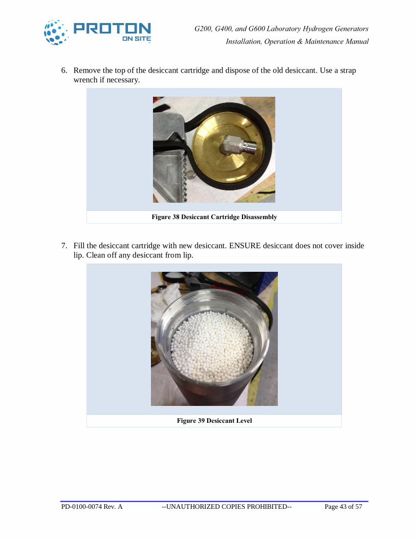
6. Remove the top of the desiccant cartridge and dispose of the old desiccant. Use a strap wrench if necessary.
Figure 38 Desiccant Cartridge Disassembly
7. Fill the desiccant cartridge with new desiccant. ENSURE desiccant does not cover inside lip. Clean off any desiccant from lip.
Figure 39 Desiccant Level
G200, G400, and G600 Laboratory Hydrogen Generators
Installation, Operation & Maintenance Manual
PD-0100-0074 Rev. A --UNAUTHORIZED COPIES PROHIBITED-- Page 44 of 57
8. Replace the top of the desiccant cartridge and tighten all the way. Loosen cap as necessary to line up fittings.
Ensure fittings on top and bottom of cartridge face the same direction. The o-ring seal of the cartridge is not dependant on full tight threads.
9. Close manual ball valve.
10. Reinstall the desiccant cartridge in the Hydrogen Generator and tighten fittings.
11. Reinstall the generator top and sides.
12. Reconnect the power cord and turn on the power switch for the Hydrogen Generator.
13. After the Hydrogen Generator boots up, Press Screen Select and select the Desiccant Timer button. (Figure 24)
14. Press the RESET DESCNT TIMER button (Figure 25)
15. Enter your customer password to login, press enter and press RESET DESCNT TIMER button again if necessary.
G200, G400, and G600 Laboratory Hydrogen Generators
Installation, Operation & Maintenance Manual
PD-0100-0074 Rev. A --UNAUTHORIZED COPIES PROHIBITED-- Page 45 of 57
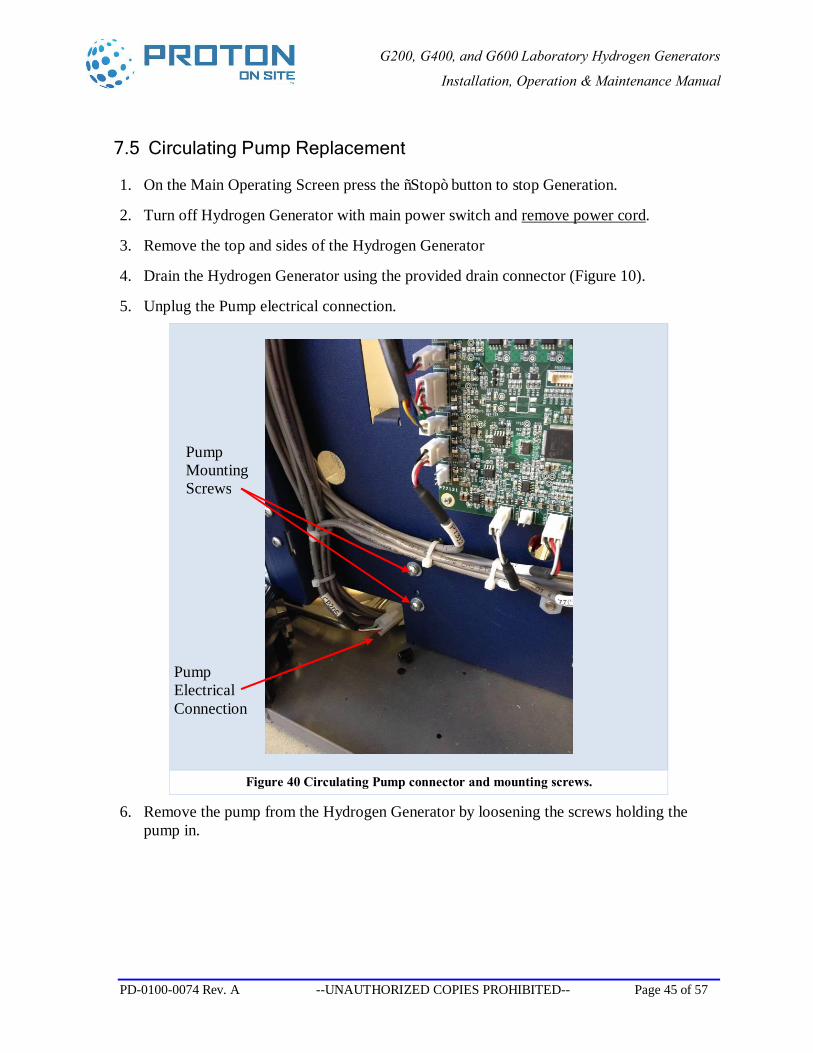
7.5 Circulating Pump Replacement
1. On the Main Operating Screen press the “Stop” button to stop Generation.
2. Turn off Hydrogen Generator with main power switch and remove power cord.
3. Remove the top and sides of the Hydrogen Generator
4. Drain the Hydrogen Generator using the provided drain connector (Figure 10).
5. Unplug the Pump electrical connection.
Figure 40 Circulating Pump connector and mounting screws.
6. Remove the pump from the Hydrogen Generator by loosening the screws holding the pump in.
Pump Electrical Connection
Pump Mounting Screws
G200, G400, and G600 Laboratory Hydrogen Generators
Installation, Operation & Maintenance Manual
PD-0100-0074 Rev. A --UNAUTHORIZED COPIES PROHIBITED-- Page 46 of 57
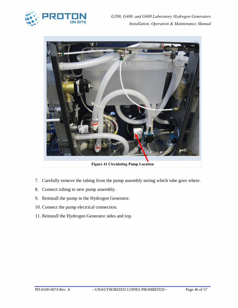
Figure 41 Circulating Pump Location
7. Carefully remove the tubing from the pump assembly noting which tube goes where.
8. Connect tubing to new pump assembly.
9. Reinstall the pump in the Hydrogen Generator.
10. Connect the pump electrical connection.
11. Reinstall the Hydrogen Generator sides and top.
G200, G400, and G600 Laboratory Hydrogen Generators
Installation, Operation & Maintenance Manual
PD-0100-0074 Rev. A --UNAUTHORIZED COPIES PROHIBITED-- Page 47 of 57
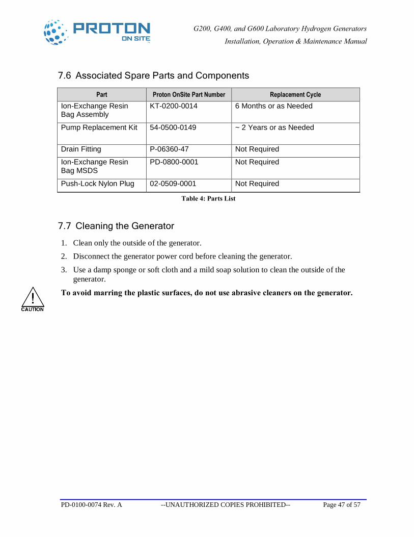
7.6 Associated Spare Parts and Components
Part Proton OnSite Part Number Replacement Cycle Ion-Exchange Resin Bag Assembly
KT-0200-0014 6 Months or as Needed
Pump Replacement Kit 54-0500-0149
~ 2 Years or as Needed
Drain Fitting P-06360-47 Not Required
Ion-Exchange Resin Bag MSDS
PD-0800-0001 Not Required
Push-Lock Nylon Plug 02-0509-0001 Not Required
Table 4: Parts List
7.7 Cleaning the Generator
1. Clean only the outside of the generator. 2. Disconnect the generator power cord before cleaning the generator.
3. Use a damp sponge or soft cloth and a mild soap solution to clean the outside of the generator.
To avoid marring the plastic surfaces, do not use abrasive cleaners on the generator.
G200, G400, and G600 Laboratory Hydrogen Generators
Installation, Operation & Maintenance Manual
PD-0100-0074 Rev. A --UNAUTHORIZED COPIES PROHIBITED-- Page 48 of 57
8 Troubleshooting
If power to the Hydrogen Generator is interrupted, hydrogen generation ceases and the unit shuts down. When electricity becomes available again, the Hydrogen Generator powers up display shows the Main Operating Screen (Figure 14), but hydrogen generation does not begin automatically. To restart hydrogen generation, simply press the “Start/Reset” button to initiate the startup process (Refer to Section 5.1).
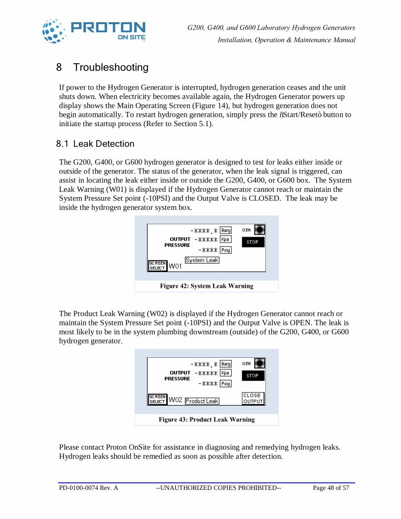
8.1 Leak Detection
The G200, G400, or G600 hydrogen generator is designed to test for leaks either inside or outside of the generator. The status of the generator, when the leak signal is triggered, can assist in locating the leak either inside or outside the G200, G400, or G600 box. The System Leak Warning (W01) is displayed if the Hydrogen Generator cannot reach or maintain the System Pressure Set point (-10PSI) and the Output Valve is CLOSED. The leak may be inside the hydrogen generator system box.
Figure 42: System Leak Warning
The Product Leak Warning (W02) is displayed if the Hydrogen Generator cannot reach or maintain the System Pressure Set point (-10PSI) and the Output Valve is OPEN. The leak is most likely to be in the system plumbing downstream (outside) of the G200, G400, or G600 hydrogen generator.
Figure 43: Product Leak Warning
Please contact Proton OnSite for assistance in diagnosing and remedying hydrogen leaks. Hydrogen leaks should be remedied as soon as possible after detection.
G200, G400, and G600 Laboratory Hydrogen Generators
Installation, Operation & Maintenance Manual
PD-0100-0074 Rev. A --UNAUTHORIZED COPIES PROHIBITED-- Page 49 of 57
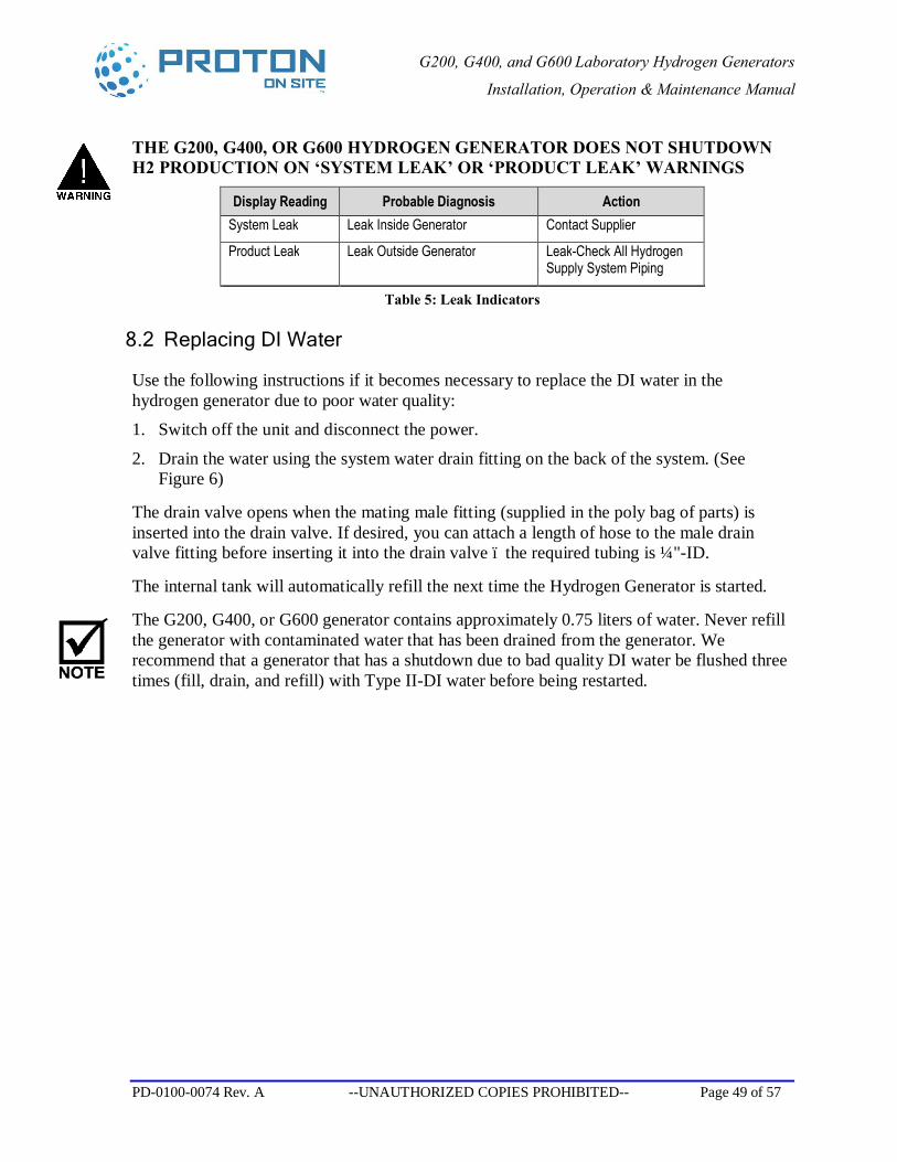
THE G200, G400, OR G600 HYDROGEN GENERATOR DOES NOT SHUTDOWN H2 PRODUCTION ON ‘SYSTEM LEAK’ OR ‘PRODUCT LEAK’ WARNINGS
Display Reading Probable Diagnosis Action System Leak Leak Inside Generator Contact Supplier
Product Leak Leak Outside Generator Leak-Check All Hydrogen Supply System Piping
Table 5: Leak Indicators
8.2 Replacing DI Water
Use the following instructions if it becomes necessary to replace the DI water in the hydrogen generator due to poor water quality: 1. Switch off the unit and disconnect the power.
2. Drain the water using the system water drain fitting on the back of the system. (See Figure 6)
The drain valve opens when the mating male fitting (supplied in the poly bag of parts) is inserted into the drain valve. If desired, you can attach a length of hose to the male drain valve fitting before inserting it into the drain valve – the required tubing is ¼"-ID.
The internal tank will automatically refill the next time the Hydrogen Generator is started.
The G200, G400, or G600 generator contains approximately 0.75 liters of water. Never refill the generator with contaminated water that has been drained from the generator. We recommend that a generator that has a shutdown due to bad quality DI water be flushed three times (fill, drain, and refill) with Type II-DI water before being restarted.
G200, G400, and G600 Laboratory Hydrogen Generators
Installation, Operation & Maintenance Manual
PD-0100-0074 Rev. A --UNAUTHORIZED COPIES PROHIBITED-- Page 50 of 57
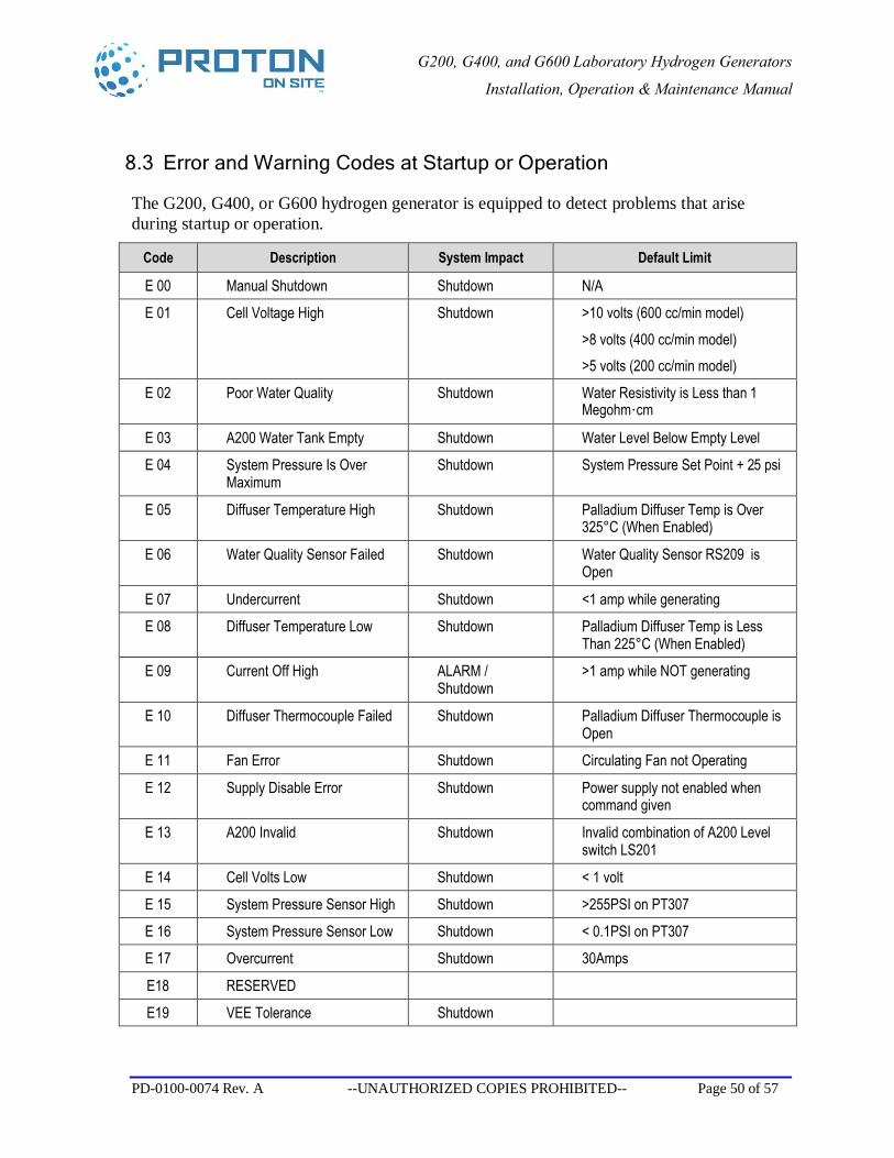
8.3 Error and Warning Codes at Startup or Operation
The G200, G400, or G600 hydrogen generator is equipped to detect problems that arise during startup or operation.
Code Description System Impact Default Limit
E 00 Manual Shutdown Shutdown N/A
E 01 Cell Voltage High Shutdown >10 volts (600 cc/min model) >8 volts (400 cc/min model) >5 volts (200 cc/min model)
E 02 Poor Water Quality Shutdown Water Resistivity is Less than 1 Megohm·cm
E 03 A200 Water Tank Empty Shutdown Water Level Below Empty Level
E 04 System Pressure Is Over Maximum
Shutdown System Pressure Set Point + 25 psi
E 05 Diffuser Temperature High Shutdown Palladium Diffuser Temp is Over 325°C (When Enabled)
E 06 Water Quality Sensor Failed Shutdown Water Quality Sensor RS209 is Open
E 07 Undercurrent Shutdown <1 amp while generating
E 08 Diffuser Temperature Low Shutdown Palladium Diffuser Temp is Less Than 225°C (When Enabled)
E 09 Current Off High ALARM / Shutdown
>1 amp while NOT generating
E 10 Diffuser Thermocouple Failed Shutdown Palladium Diffuser Thermocouple is Open
E 11 Fan Error Shutdown Circulating Fan not Operating
E 12 Supply Disable Error Shutdown Power supply not enabled when command given
E 13 A200 Invalid Shutdown Invalid combination of A200 Level switch LS201
E 14 Cell Volts Low Shutdown < 1 volt
E 15 System Pressure Sensor High Shutdown >255PSI on PT307
E 16 System Pressure Sensor Low Shutdown < 0.1PSI on PT307
E 17 Overcurrent Shutdown 30Amps
E18 RESERVED
E19 VEE Tolerance Shutdown
G200, G400, and G600 Laboratory Hydrogen Generators
Installation, Operation & Maintenance Manual
PD-0100-0074 Rev. A --UNAUTHORIZED COPIES PROHIBITED-- Page 51 of 57
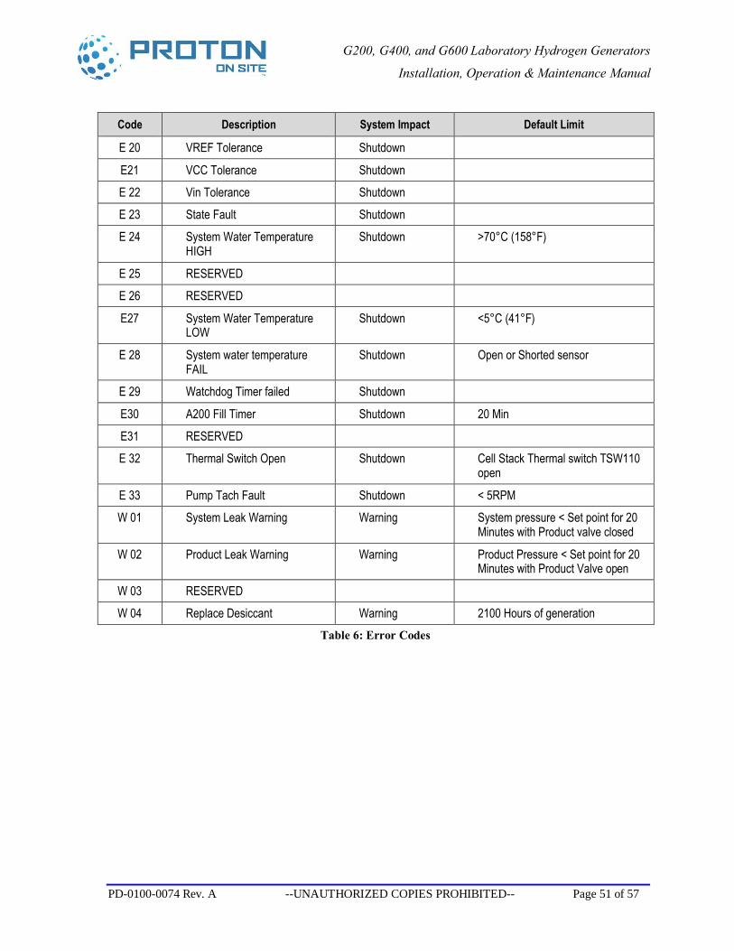
Code Description System Impact Default Limit
E 20 VREF Tolerance Shutdown
E21 VCC Tolerance Shutdown
E 22 Vin Tolerance Shutdown
E 23 State Fault Shutdown
E 24 System Water Temperature HIGH
Shutdown >70°C (158°F)
E 25 RESERVED
E 26 RESERVED
E27 System Water Temperature LOW
Shutdown <5°C (41°F)
E 28 System water temperature FAIL
Shutdown Open or Shorted sensor
E 29 Watchdog Timer failed Shutdown
E30 A200 Fill Timer Shutdown 20 Min
E31 RESERVED
E 32 Thermal Switch Open Shutdown Cell Stack Thermal switch TSW110 open
E 33 Pump Tach Fault Shutdown < 5RPM
W 01 System Leak Warning Warning System pressure < Set point for 20 Minutes with Product valve closed
W 02 Product Leak Warning Warning Product Pressure < Set point for 20 Minutes with Product Valve open
W 03 RESERVED
W 04 Replace Desiccant Warning 2100 Hours of generation Table 6: Error Codes
G200, G400, and G600 Laboratory Hydrogen Generators
Installation, Operation & Maintenance Manual
PD-0100-0074 Rev. A --UNAUTHORIZED COPIES PROHIBITED-- Page 52 of 57
9 Frequently Asked Questions
What is a “System Pressure Leak” warning? If the G200, G400, or G600 generator is unable to achieve or maintain the system pressure set point with the product valve closed, System Pressure Leak flashes in the display read-out. The timeout is set to 20 minutes at the factory.
What is a “Product Pressure Leak” warning? If the G200, G400, or G600 generator is unable to achieve or maintain the system pressure set point with the product valve open, Product Pressure Leak flashes in the display read-out. The timeout is set to 20 minutes at the factory.
If the leak warning is triggered, how can I determine the specific leak points in my systems? If the generator is delivering gas at the time a Product Pressure Leak signal is triggered, then the leak is most likely to be outside the generator system in the hydrogen supply piping. Check all piping and fittings from the hydrogen generator downstream to the instruments for leak tightness. Be aware that the leak alarm is a warning only and the system is unable to fill the supply piping to pressure within the allotted time. If the supply piping system is large in diameter or if the generator is located far from the instruments using the hydrogen, it is acceptable to ignore the alarm temporarily to see if the unit comes up to pressure and emerges from the alarm condition. To check for hydrogen leaks in piping outside of the G200, G400, or G600 hydrogen generator, Proton OnSite suggests using a liquid leak detector solution or a handheld combustible gas detector.
If the SYSTEM PRESSURE LEAK warning is triggered when the generator is in Standby Mode (internal pressure), but not delivering gas, the leak is likely to be within the system. Call Proton OnSite or your supplier for servicing information.
What is the ion-exchange resin bag? The ion-exchange resin bag scavenges any remaining ions from the water re-circulated within the system. The ion scavenging helps to stop the water conductivity from rising during operation. High ion levels in the water trigger the water quality shutdown to avoid irreversibly damaging the cell stack.
How often should this ion-exchange resin bag be replaced? The ion-exchange resin bag should be replaced at least every six months. All of the water must be drained and replaced with good quality DI water. The ion-exchange resin bag must be replaced if the water quality sensor is triggered and the unit shuts down for poor quality (impure) water.
G200, G400, and G600 Laboratory Hydrogen Generators
Installation, Operation & Maintenance Manual
PD-0100-0074 Rev. A --UNAUTHORIZED COPIES PROHIBITED-- Page 53 of 57
How do I stop hydrogen flow, but still maintain internal pressure without a complete unit shutdown? To stop hydrogen delivery, but maintain internal hydrogen pressure within the generator for instant restart, press the Close Output button to close the solenoid valve and cease hydrogen delivery.
How do I perform a complete unit shutdown? To stop hydrogen delivery and depressurize the unit completely, press the “Stop” button to shut down the generator. The digital display panel reads “E-00,” which is the error code for a manual shutdown.
For emergency shutdown, simply shut off the power using the power switch in the back of the generator or unplug the unit. Shutting off the power does not damage the system, but it takes time to restart and begin producing hydrogen after the power is shut off.
What is an E-02 error (poor water quality)? The G200, G400, or G600 hydrogen generator is designed to operate using DI water that has a resistivity of 1 Megohm·cm or better. If lower quality DI or distilled water is used in the unit, it shuts down the system and triggers the audible alarm and digital error code display. The water quality shutdown is designed to protect the hydrogen production cell stack in the system from irreparable damage due to the use of water that does not meet the specifications. Use of water that is not of the required quality may irreversibly damage the unit cell stack and voids the warranty.
How often should I flush the water? To extend the life of the unit, Proton OnSite recommends that the water should be flushed on a monthly basis and refilled with the specified 1 Megohm·cm or better rating.
G200, G400, and G600 Laboratory Hydrogen Generators
Installation, Operation & Maintenance Manual
PD-0100-0074 Rev. A --UNAUTHORIZED COPIES PROHIBITED-- Page 54 of 57
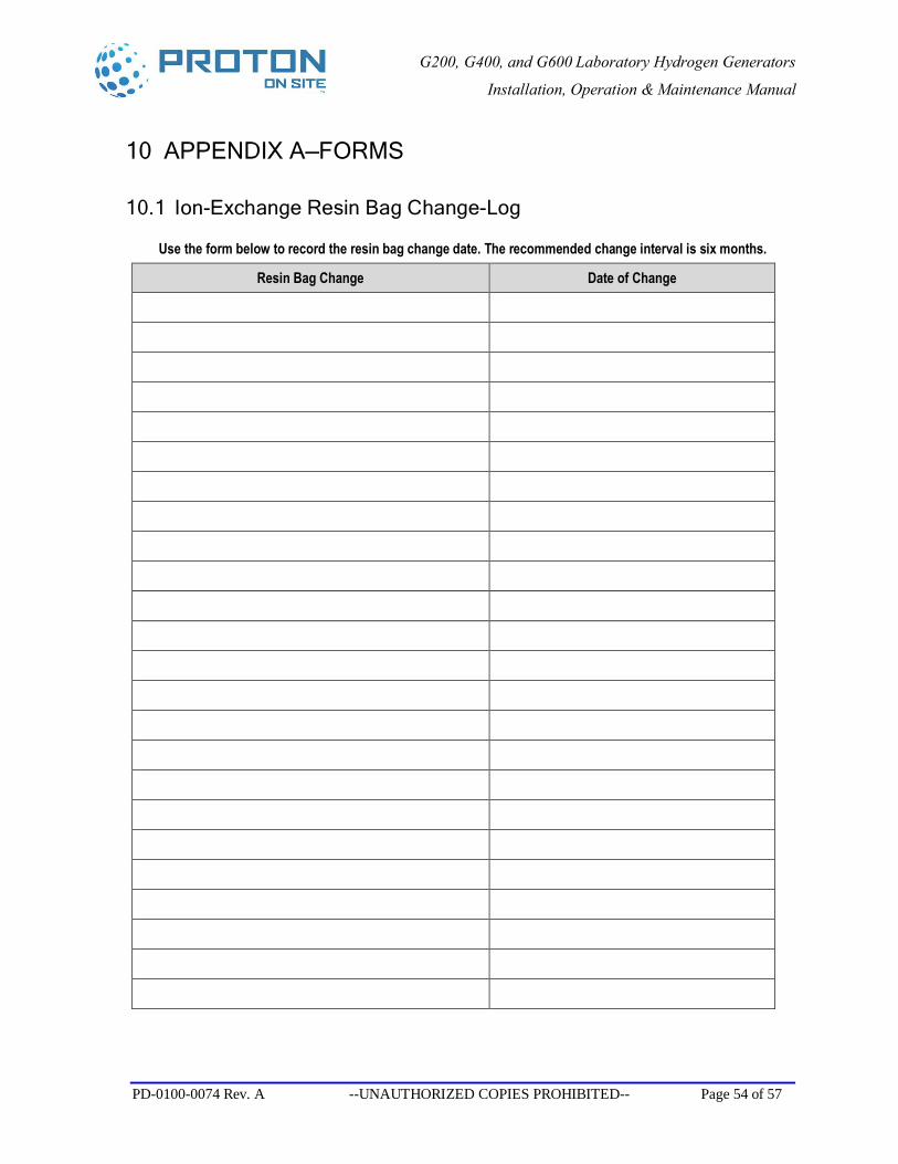
10 APPENDIX A—FORMS
10.1 Ion-Exchange Resin Bag Change-Log
Use the form below to record the resin bag change date. The recommended change interval is six months.
Resin Bag Change Date of Change
G200, G400, and G600 Laboratory Hydrogen Generators
Installation, Operation & Maintenance Manual
PD-0100-0074 Rev. A --UNAUTHORIZED COPIES PROHIBITED-- Page 55 of 57
10.2 Customer Registration Form
Please fill out the form on the last page, tear it out of the manual, and fax it to Proton OnSite (Fax Number: 1-203-949-8016) to ensure that your G200, G400, or G600 Hydrogen Generator is properly registered. The form may also be sent by mail to the following address:
Customer Service Proton OnSite, Inc. 10 Technology Drive Wallingford, CT 06492
Proper registration is important for product support and automatic notification regarding routine maintenance.
G200, G400, and G600 Laboratory Hydrogen Generators
Installation, Operation & Maintenance Manual
PD-0100-0074 Rev. A --UNAUTHORIZED COPIES PROHIBITED-- Page 56 of 57
This page is intentionally left blank.
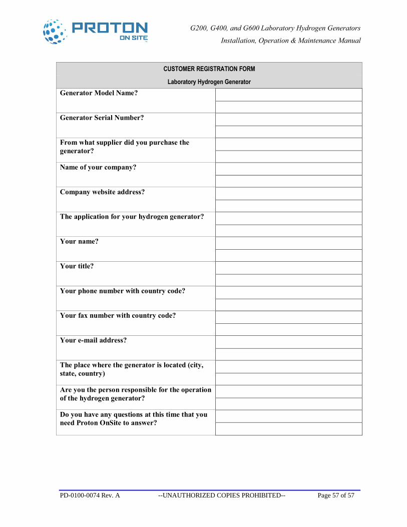
G200, G400, and G600 Laboratory Hydrogen Generators
Installation, Operation & Maintenance Manual
PD-0100-0074 Rev. A --UNAUTHORIZED COPIES PROHIBITED-- Page 57 of 57
CUSTOMER REGISTRATION FORM
Laboratory Hydrogen Generator Generator Model Name?
Generator Serial Number?
From what supplier did you purchase the generator?
Name of your company?
Company website address?
The application for your hydrogen generator?
Your name?
Your title?
Your phone number with country code?
Your fax number with country code?
Your e-mail address?
The place where the generator is located (city, state, country)
Are you the person responsible for the operation of the hydrogen generator?
Do you have any questions at this time that you need Proton OnSite to answer?